Embed Size (px)
Citation preview
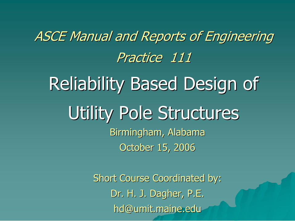
ASCE Manual and Reports of Engineering ASCE Manual and Reports of Engineering
Practice 111 Practice 111
Reliability Based Design of Reliability Based Design of
Utility Pole Structures Utility Pole Structures Birmingham, Alabama Birmingham, Alabama
October 15, 2006 October 15, 2006
Short Course Coordinated by: Short Course Coordinated by:
Dr. H. J. Dr. H. J. Dagher Dagher, P.E. , P.E.
10/15/06 10/15/06 ASCE Manual 111 Workshop ASCE Manual 111 Workshop 2 2
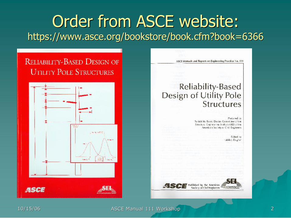
Order from ASCE website: Order from ASCE website: https:// https://www.asce.org/bookstore/book.cfm?book www.asce.org/bookstore/book.cfm?book=6366 =6366
10/15/06 10/15/06 ASCE Manual 111 Workshop ASCE Manual 111 Workshop 3 3
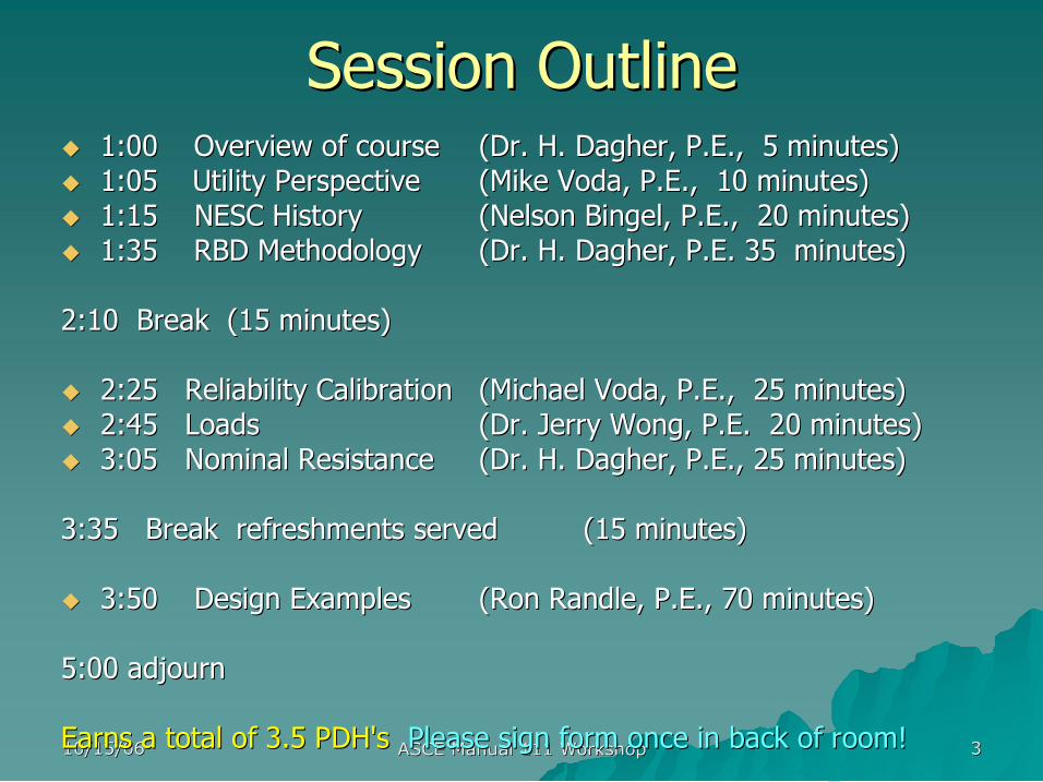
Session Outline Session Outline u u 1:00 Overview of course 1:00 Overview of course (Dr. H. (Dr. H. Dagher Dagher, P.E., 5 minutes) , P.E., 5 minutes) u u 1:05 1:05 Utility Perspective Utility Perspective (Mike (Mike Voda Voda, P.E., 10 minutes) , P.E., 10 minutes) u u 1:15 NESC History 1:15 NESC History (Nelson (Nelson Bingel Bingel, P.E., 20 minutes) , P.E., 20 minutes) u u 1:35 RBD Methodology 1:35 RBD Methodology (Dr. H. (Dr. H. Dagher Dagher, P.E. 35 minutes) , P.E. 35 minutes)
2:10 Break (15 minutes) 2:10 Break (15 minutes)
u u 2:25 Reliability Calibration 2:25 Reliability Calibration (Michael (Michael Voda Voda, P.E., 25 minutes) , P.E., 25 minutes) u u 2:45 Loads 2:45 Loads (Dr. Jerry Wong, P.E. 20 minutes) (Dr. Jerry Wong, P.E. 20 minutes) u u 3:05 Nominal Resistance 3:05 Nominal Resistance (Dr. H. (Dr. H. Dagher Dagher, P.E., 25 minutes) , P.E., 25 minutes)
3:35 Break refreshments served 3:35 Break refreshments served (15 minutes) (15 minutes)
u u 3:50 Design Examples 3:50 Design Examples (Ron Randle, P.E., 70 minutes) (Ron Randle, P.E., 70 minutes)
5:00 adjourn 5:00 adjourn
Earns a total of 3.5 Earns a total of 3.5 PDH's PDH's Please sign form once in back of room! Please sign form once in back of room!

10/15/06 10/15/06 ASCE Manual 111 Workshop ASCE Manual 111 Workshop 4 4
Thank You Committee Members! Thank You Committee Members!
u u Dr. Jerry Wong Dr. Jerry Wong FPL FPL u u Magdi Magdi Ishac Ishac Hydro 1 Hydro 1 u u Brian Brian Lacoursiere Lacoursiere IUSI IUSI u u Camille Camille Rubeiz Rubeiz AISI AISI u u Dr. James Davidson Dr. James Davidson Shakespeare Shakespeare u u Wes Oliphant Wes Oliphant Newmark Newmark u u David West David West Duke Energy Duke Energy u u Martin Rollins Martin Rollins HM Rollins HM Rollins u u Gary Bowles Gary Bowles Electrical Consultants Electrical Consultants u u Larry Slavin Larry Slavin Outside Cons. Outside Cons. u u Alec Alec Zoltoochin Zoltoochin BC Hydro BC Hydro

10/15/06 10/15/06 ASCE Manual 111 Workshop ASCE Manual 111 Workshop 5 5
The Utility Perspective The Utility Perspective
presented by presented by
Michael Voda, P.E. Michael Voda, P.E. – – Principal Civil Engineer Principal Civil Engineer
Salt River Project Salt River Project

10/15/06 10/15/06 ASCE Manual 111 Workshop ASCE Manual 111 Workshop 6 6
The Utility Perspective The Utility Perspective
RBD? RBD?
We don We don’ ’t need no t need no stink stink’ ’n n RBD! RBD!
10/15/06 10/15/06 ASCE Manual 111 Workshop ASCE Manual 111 Workshop 7 7
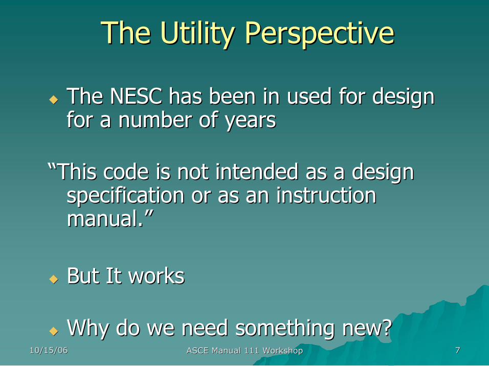
u u The NESC has been in used for design The NESC has been in used for design for a number of years for a number of years
“ “This code is not intended as a design This code is not intended as a design specification or as an instruction specification or as an instruction manual. manual.” ”
u u But It works But It works
u u Why do we need something new? Why do we need something new?
The Utility Perspective The Utility Perspective
10/15/06 10/15/06 ASCE Manual 111 Workshop ASCE Manual 111 Workshop 8 8
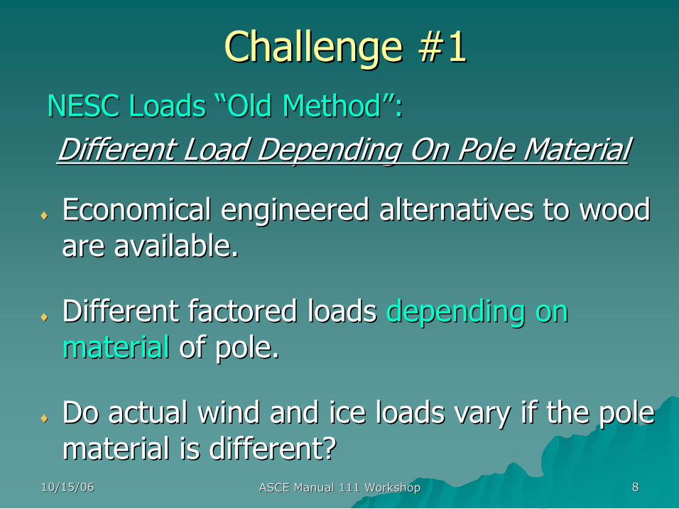
Challenge #1 Challenge #1 NESC NESC Loads Loads “ “Old Method Old Method” ”: : Different Load Depending On Pole Material Different Load Depending On Pole Material
♦ ♦ Economical engineered alternatives to wood Economical engineered alternatives to wood are available. are available.
♦ ♦ Different factored loads Different factored loads depending on depending on material material of pole. of pole.
♦ ♦ Do actual wind and ice loads vary if the pole Do actual wind and ice loads vary if the pole material is different? material is different?
10/15/06 10/15/06 ASCE Manual 111 Workshop ASCE Manual 111 Workshop 9 9
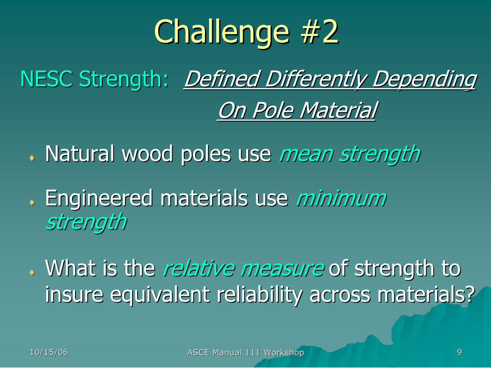
Challenge #2 Challenge #2 NESC Strength: NESC Strength: Defined Differently Depending Defined Differently Depending
On Pole Material On Pole Material
♦ ♦ Natural wood poles use Natural wood poles use mean strength mean strength
♦ ♦ Engineered materials use Engineered materials use minimum minimum strength strength
♦ ♦ What is the What is the relative measure relative measure of strength to of strength to insure equivalent reliability across materials? insure equivalent reliability across materials?
10/15/06 10/15/06 ASCE Manual 111 Workshop ASCE Manual 111 Workshop 10 10
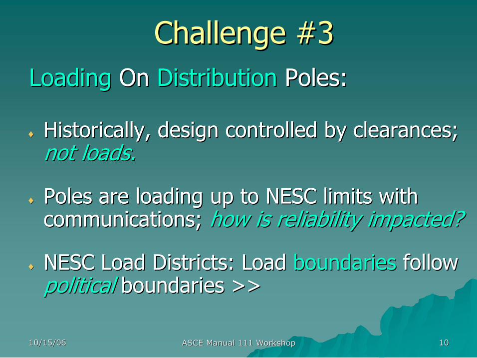
Challenge #3 Challenge #3 Loading Loading On On Distribution Distribution Poles: Poles:
♦ ♦ Historically, design controlled by clearances; Historically, design controlled by clearances; not loads. not loads.
♦ ♦ Poles are loading up to NESC limits with Poles are loading up to NESC limits with communications; communications; how is reliability impacted? how is reliability impacted?
♦ ♦ NESC Load Districts: Load NESC Load Districts: Load boundaries boundaries follow follow political political boundaries >> boundaries >>
10/15/06 10/15/06 ASCE Manual 111 Workshop ASCE Manual 111 Workshop 11 11
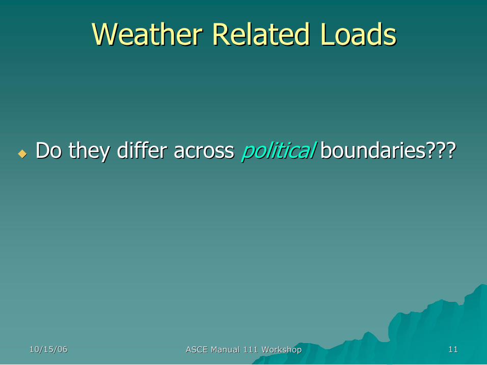
Weather Related Loads Weather Related Loads
u u Do they differ across Do they differ across political political boundaries??? boundaries???
10/15/06 10/15/06 ASCE Manual 111 Workshop ASCE Manual 111 Workshop 12 12
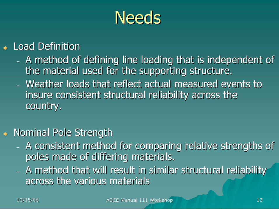
Needs Needs
u u Load Definition Load Definition – – A method of defining line loading that is independent of A method of defining line loading that is independent of the material used for the supporting structure. the material used for the supporting structure.
– – Weather loads that reflect actual measured events to Weather loads that reflect actual measured events to insure consistent structural reliability across the insure consistent structural reliability across the country. country.
u u Nominal Pole Strength Nominal Pole Strength – – A consistent method for comparing relative strengths of A consistent method for comparing relative strengths of poles made of differing materials. poles made of differing materials.
– – A method that will result in similar structural reliability A method that will result in similar structural reliability across the various materials across the various materials

10/15/06 10/15/06 ASCE Manual 111 Workshop ASCE Manual 111 Workshop 13 13
Next: Next:
NESC NESC A Historical Perspective A Historical Perspective
presented by presented by
Nelson Bingel Nelson Bingel – – VP VP Engineering Engineering Osmose Utilities Services Osmose Utilities Services

10/15/06 10/15/06 ASCE Manual 111 Workshop ASCE Manual 111 Workshop 14 14
10/15/06 10/15/06 ASCE Manual 111 Workshop ASCE Manual 111 Workshop 15 15

10/15/06 10/15/06 ASCE Manual 111 Workshop ASCE Manual 111 Workshop 16 16
National Electrical Safety Code National Electrical Safety Code

10/15/06 10/15/06 ASCE Manual 111 Workshop ASCE Manual 111 Workshop 17 17
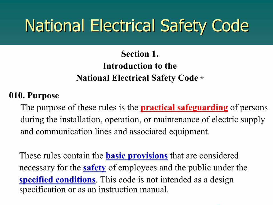
National Electrical Safety Code National Electrical Safety Code Section 1.
Introduction to the National Electrical Safety Code ®
010. Purpose The purpose of these rules is the practical safeguarding of persons during the installation, operation, or maintenance of electric supply and communication lines and associated equipment.
These rules contain the basic provisions that are considered necessary for the safety of employees and the public under the specified conditions. This code is not intended as a design specification or as an instruction manual.

10/15/06 10/15/06 ASCE Manual 111 Workshop ASCE Manual 111 Workshop 18 18
National Electrical Safety Code National Electrical Safety Code Section 1.
Introduction to the National Electrical Safety Code ®
010. Purpose The purpose of these rules is the practical safeguarding of persons during the installation, operation, or maintenance of electric supply and communication lines and associated equipment.
These rules contain the basic provisions that are considered necessary for the safety of employees and the public under the specified conditions. This code is not intended as a design specification or as an instruction manual.
10/15/06 10/15/06 ASCE Manual 111 Workshop ASCE Manual 111 Workshop 19 19
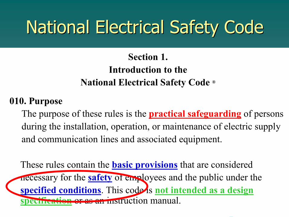
National Electrical Safety Code National Electrical Safety Code Section 1.
Introduction to the National Electrical Safety Code ®
010. Purpose The purpose of these rules is the practical safeguarding of persons during the installation, operation, or maintenance of electric supply and communication lines and associated equipment.
These rules contain the basic provisions that are considered necessary for the safety of employees and the public under the specified conditions. This code is not intended as a design specification or as an instruction manual.
10/15/06 10/15/06 ASCE Manual 111 Workshop ASCE Manual 111 Workshop 20 20
National Electrical Safety Code National Electrical Safety Code Section 1.
Introduction to the National Electrical Safety Code ®
010. Purpose The purpose of these rules is the practical safeguarding of persons during the installation, operation, or maintenance of electric supply and communication lines and associated equipment.
These rules contain the basic provisions that are considered necessary for the safety of employees and the public under the specified conditions. This code is not intended as a design specification or as an instruction manual.

10/15/06 10/15/06 ASCE Manual 111 Workshop ASCE Manual 111 Workshop 21 21
National Electrical Safety Code National Electrical Safety Code
safety of employees and the public under the specified conditions.
10/15/06 10/15/06 ASCE Manual 111 Workshop ASCE Manual 111 Workshop 22 22
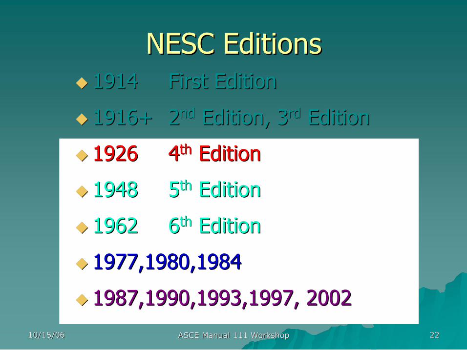
NESC Editions NESC Editions u u 1914 1914 First Edition First Edition
u u 1916+ 1916+ 2 2 nd nd Edition, 3 Edition, 3 rd rd Edition Edition
u u 1926 1926 4 4 th th Edition Edition
u u 1948 1948 5 5 th th Edition Edition
u u 1962 1962 6 6 th th Edition Edition
u u 1977,1980,1984 1977,1980,1984
u u 1987,1990,1993,1997, 2002 1987,1990,1993,1997, 2002
10/15/06 10/15/06 ASCE Manual 111 Workshop ASCE Manual 111 Workshop 23 23
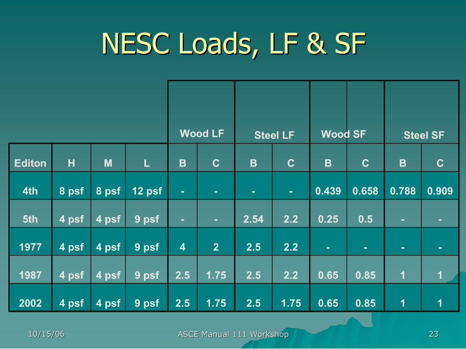
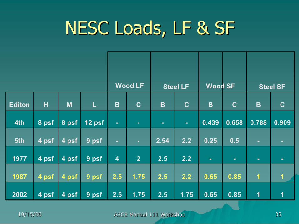
NESC Loads, LF & SF NESC Loads, LF & SF
1 1 0.85 0.65 1.75 2.5 1.75 2.5 9 psf 4 psf 4 psf 2002
1 1 0.85 0.65 2.2 2.5 1.75 2.5 9 psf 4 psf 4 psf 1987
2.2 2.5 2 4 9 psf 4 psf 4 psf 1977
0.5 0.25 2.2 2.54 9 psf 4 psf 4 psf 5th
0.909 0.788 0.658 0.439 12 psf 8 psf 8 psf 4th
C B C B C B C B L M H Editon
Steel SF Steel LF Wood LF Wood SF

10/15/06 10/15/06 ASCE Manual 111 Workshop ASCE Manual 111 Workshop 24 24
LONGINTUDINAL
TRANSVERSE
V E R T I C A L
10/15/06 10/15/06 ASCE Manual 111 Workshop ASCE Manual 111 Workshop 25 25
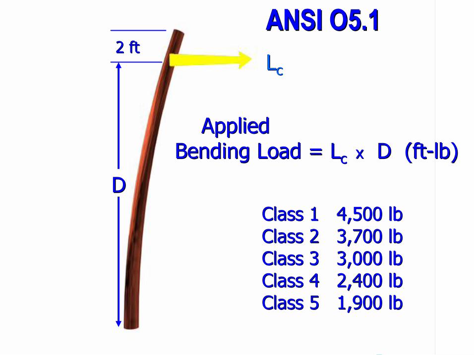
L L c c
D D
2 ft 2 ft
Class 1 4,500 lb Class 1 4,500 lb Class 2 3,700 lb Class 2 3,700 lb Class 3 3,000 lb Class 3 3,000 lb Class 4 2,400 lb Class 4 2,400 lb Class 5 1,900 lb Class 5 1,900 lb
ANSI O5.1 ANSI O5.1
Applied Applied Bending Load = Bending Load = L L c c x x D (ft D (ft lb) lb)
10/15/06 10/15/06 ASCE Manual 111 Workshop ASCE Manual 111 Workshop 26 26
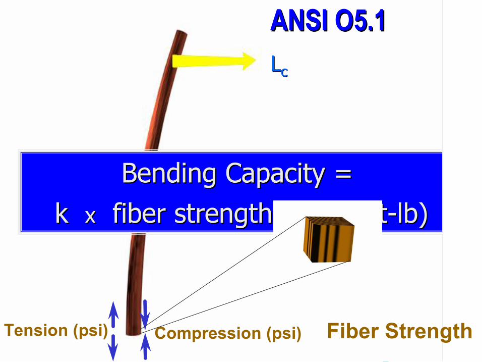
L L c c
Compression (psi) Tension (psi)
Bending Capacity = Bending Capacity = k k x x fiber strength fiber strength x x C C 3 3 (ft (ft lb) lb)
Fiber Strength
ANSI O5.1 ANSI O5.1
10/15/06 10/15/06 ASCE Manual 111 Workshop ASCE Manual 111 Workshop 27 27
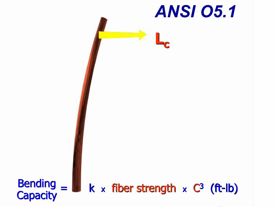
L L c c
k k x x fiber strength fiber strength x x C C 3 3 (ft (ft lb) lb)
ANSI O5.1
Bending Bending Capacity Capacity
= = k k x x fiber strength fiber strength x x C C 3 3 (ft (ft lb) lb) k k x x fiber strength fiber strength x x C C 3 3 (ft (ft lb) lb)
L L c c
10/15/06 10/15/06 ASCE Manual 111 Workshop ASCE Manual 111 Workshop 28 28
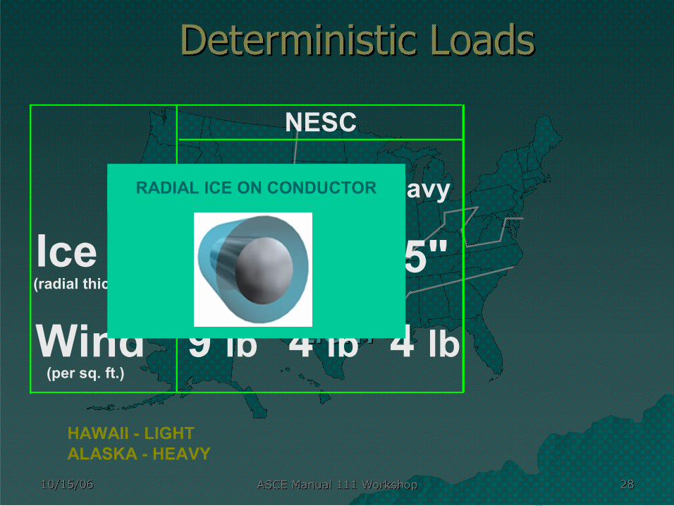
HEAVY HEAVY
HAWAII LIGHT ALASKA HEAVY
MEDIUM MEDIUM
LIGHT LIGHT
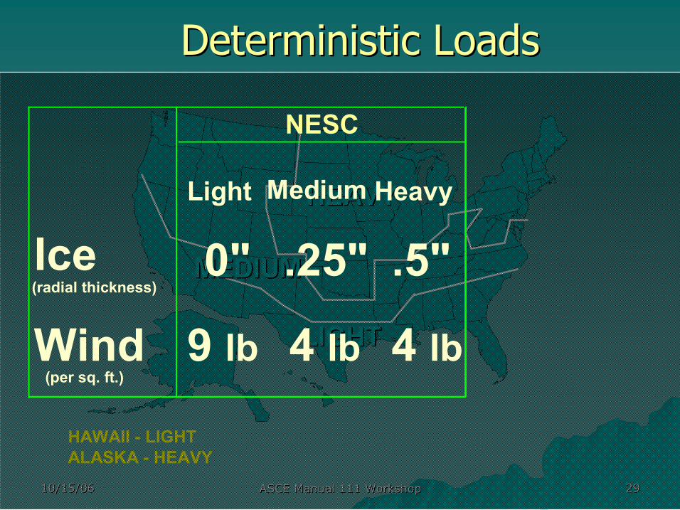
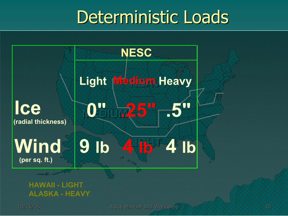
Deterministic Loads Deterministic Loads
Light Medium Heavy
Ice 0" .25" .5" (radial thickness)
Wind 9 lb 4 lb 4 lb (per sq. ft.)
NESC
RADIAL ICE ON CONDUCTOR
10/15/06 10/15/06 ASCE Manual 111 Workshop ASCE Manual 111 Workshop 29 29
HEAVY HEAVY
HAWAII LIGHT ALASKA HEAVY
MEDIUM MEDIUM
LIGHT LIGHT
Deterministic Loads Deterministic Loads
Light Medium Heavy
Ice 0" .25" .5" (radial thickness)
Wind 9 lb 4 lb 4 lb (per sq. ft.)
NESC
10/15/06 10/15/06 ASCE Manual 111 Workshop ASCE Manual 111 Workshop 30 30
HEAVY HEAVY
HAWAII LIGHT ALASKA HEAVY
MEDIUM MEDIUM
LIGHT LIGHT
Deterministic Loads Deterministic Loads
Light Medium Heavy
Ice 0" .25" .5" (radial thickness)
Wind 9 lb 4 lb 4 lb (per sq. ft.)
NESC
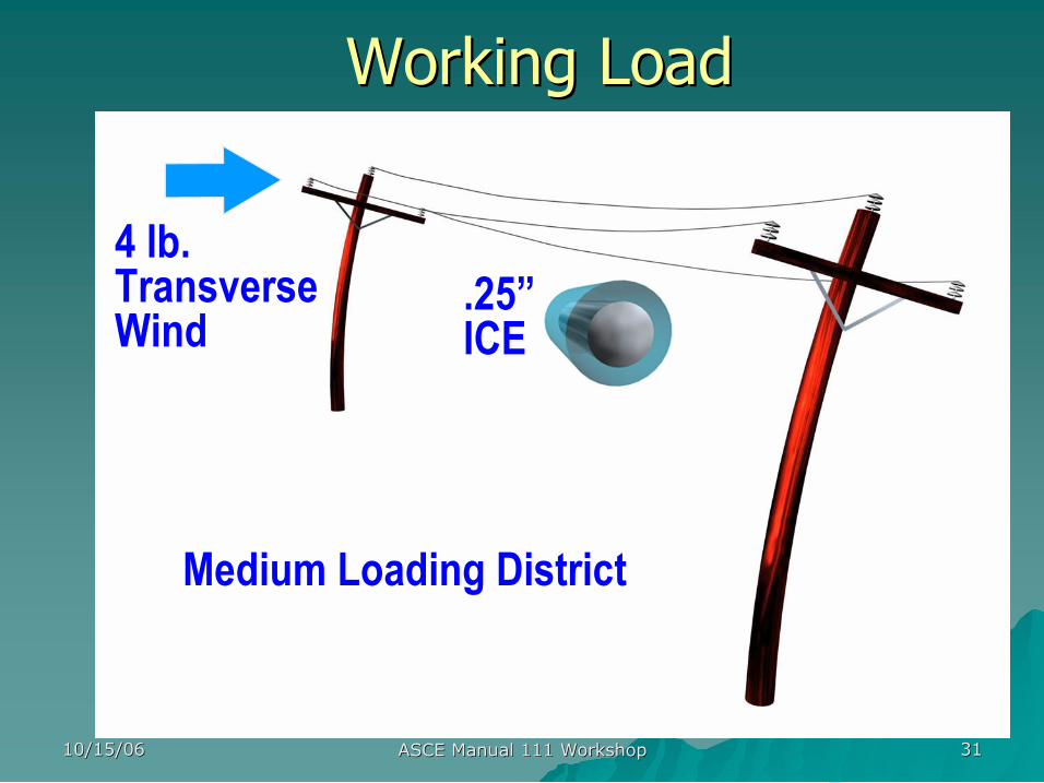
10/15/06 10/15/06 ASCE Manual 111 Workshop ASCE Manual 111 Workshop 31 31
4 lb. Transverse Wind
.25” ICE
Working Load Working Load
Medium Loading District
10/15/06 10/15/06 ASCE Manual 111 Workshop ASCE Manual 111 Workshop 32 32
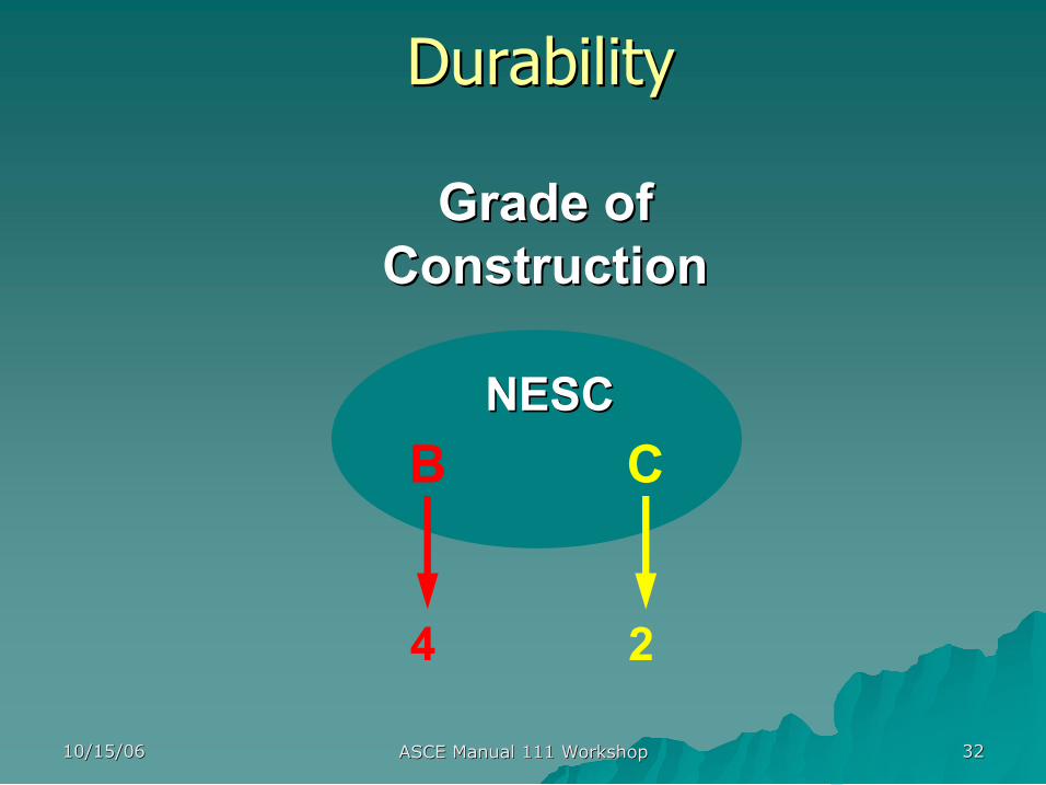
Durability Durability
Grade of Grade of Construction Construction
NESC NESC B C
4 2
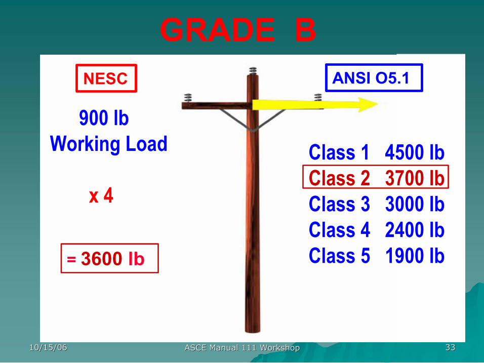
10/15/06 10/15/06 ASCE Manual 111 Workshop ASCE Manual 111 Workshop 33 33
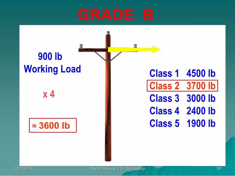
GRADE B
900 lb Working Load
x 4
Class 1 4500 lb Class 2 3700 lb Class 3 3000 lb Class 4 2400 lb Class 5 1900 lb = 3600 lb
NESC ANSI O5.1
10/15/06 10/15/06 ASCE Manual 111 Workshop ASCE Manual 111 Workshop 34 34
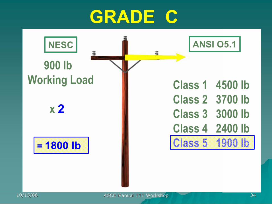
GRADE C
900 lb Working Load
x 2
Class 1 4500 lb Class 2 3700 lb Class 3 3000 lb Class 4 2400 lb Class 5 1900 lb = 1800 lb
NESC ANSI O5.1
10/15/06 10/15/06 ASCE Manual 111 Workshop ASCE Manual 111 Workshop 35 35
NESC Loads, LF & SF NESC Loads, LF & SF
1 1 0.85 0.65 1.75 2.5 1.75 2.5 9 psf 4 psf 4 psf 2002
1 1 0.85 0.65 2.2 2.5 1.75 2.5 9 psf 4 psf 4 psf 1987
2.2 2.5 2 4 9 psf 4 psf 4 psf 1977
0.5 0.25 2.2 2.54 9 psf 4 psf 4 psf 5th
0.909 0.788 0.658 0.439 12 psf 8 psf 8 psf 4th
C B C B C B C B L M H Editon
Steel SF Steel LF Wood LF Wood SF
10/15/06 10/15/06 ASCE Manual 111 Workshop ASCE Manual 111 Workshop 36 36
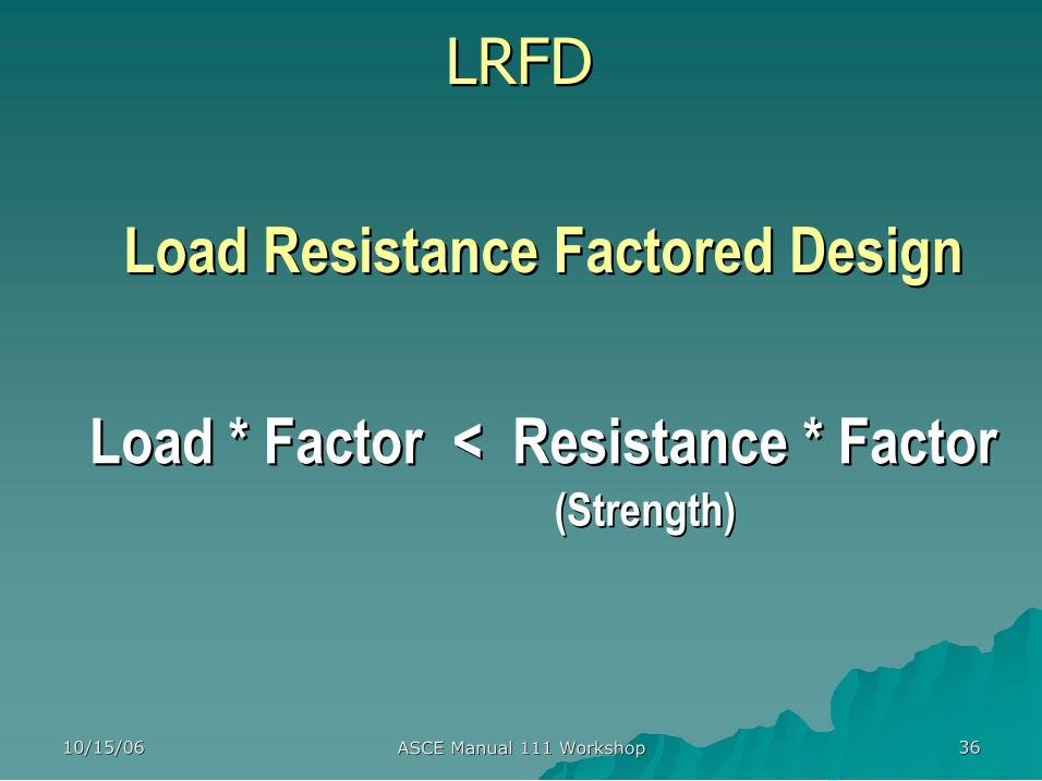
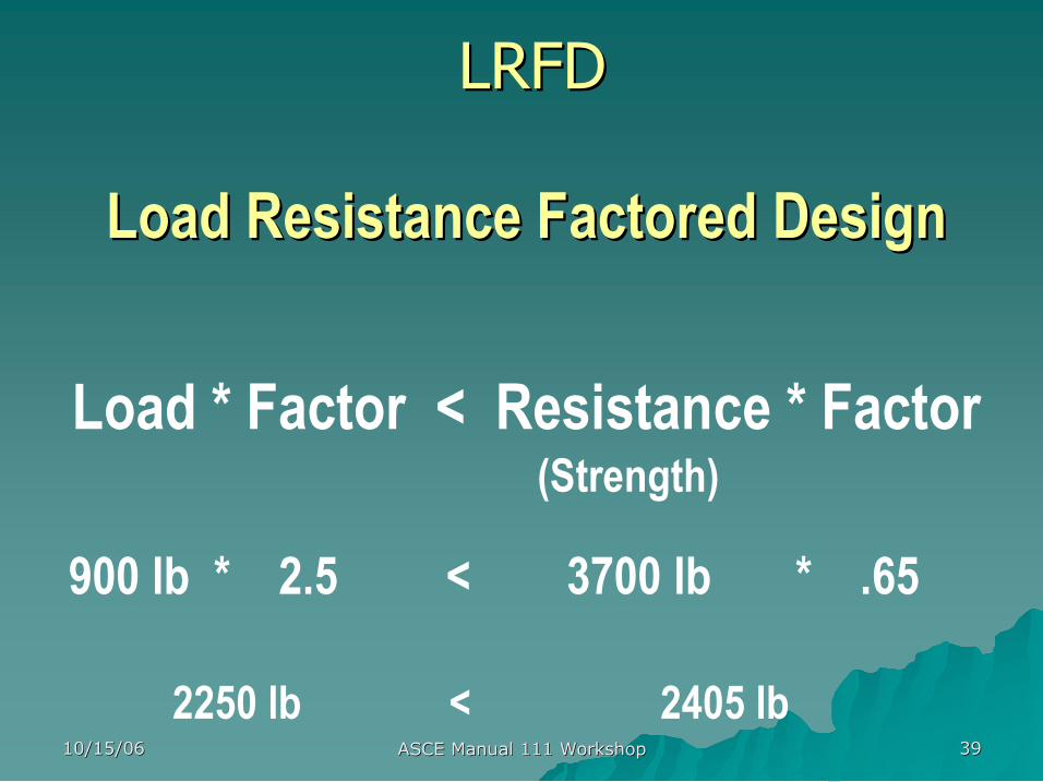
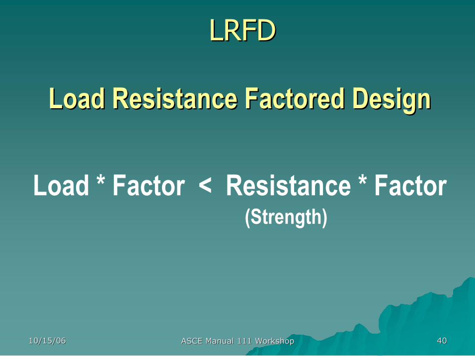
Load Resistance Factored Design Load Resistance Factored Design
Load * Factor < Resistance * Factor Load * Factor < Resistance * Factor (Strength) (Strength)
LRFD LRFD
10/15/06 10/15/06 ASCE Manual 111 Workshop ASCE Manual 111 Workshop 37 37
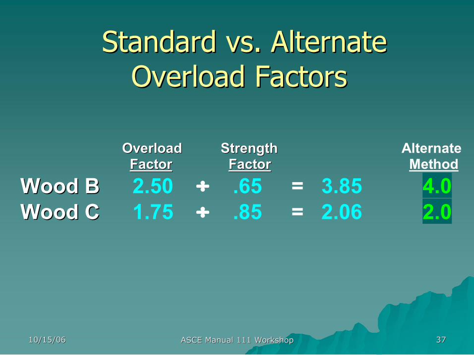
Overload Strength Overload Strength Alternate Factor Factor Factor Factor Method
Wood B Wood B 2.50 ÷ .65 = 3.85 4.0 Wood C Wood C 1.75 ÷ .85 = 2.06 2.0
Standard vs. Alternate Standard vs. Alternate Overload Factors Overload Factors
10/15/06 10/15/06 ASCE Manual 111 Workshop ASCE Manual 111 Workshop 38 38
GRADE B
900 lb Working Load
x 4
Class 1 4500 lb Class 2 3700 lb Class 3 3000 lb Class 4 2400 lb Class 5 1900 lb = 3600 lb
10/15/06 10/15/06 ASCE Manual 111 Workshop ASCE Manual 111 Workshop 39 39
Load Resistance Factored Design Load Resistance Factored Design
Load * Factor < Resistance * Factor (Strength)
900 lb * 2.5 < 3700 lb * .65
2250 lb < 2405 lb
LRFD LRFD
10/15/06 10/15/06 ASCE Manual 111 Workshop ASCE Manual 111 Workshop 40 40
Load Resistance Factored Design Load Resistance Factored Design
Load * Factor < Resistance * Factor (Strength)
LRFD LRFD
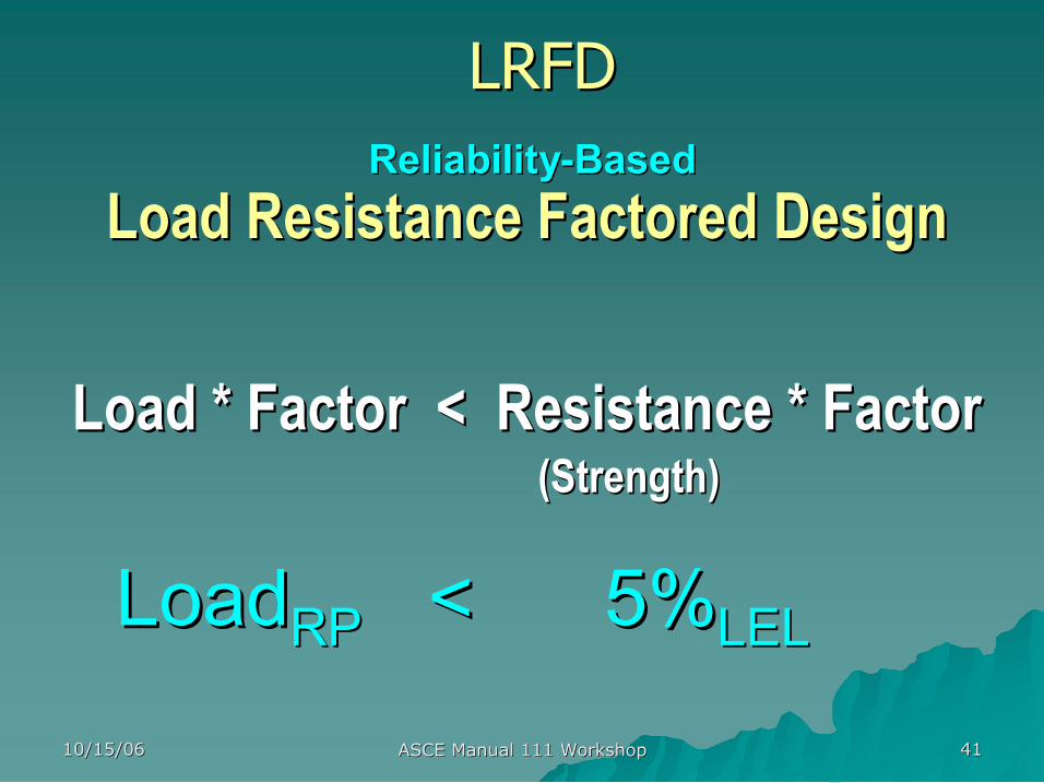
10/15/06 10/15/06 ASCE Manual 111 Workshop ASCE Manual 111 Workshop 41 41
Load Resistance Factored Design Load Resistance Factored Design
Load * Factor < Resistance * Factor Load * Factor < Resistance * Factor (Strength) (Strength)
LRFD LRFD Reliability Reliability Based Based
Load Load RP RP < 5% < 5% LEL LEL
10/15/06 10/15/06 ASCE Manual 111 Workshop ASCE Manual 111 Workshop 42 42
10/15/06 10/15/06 ASCE Manual 111 Workshop ASCE Manual 111 Workshop 43 43

RBD Methodology RBD Methodology presented by presented by
Dr. H. J. Dagher, P.E. Dr. H. J. Dagher, P.E.
Director, Advanced Structures and Director, Advanced Structures and
Composites Laboratory Composites Laboratory
University of Maine University of Maine
Next: Next:
10/15/06 10/15/06 ASCE Manual 111 Workshop ASCE Manual 111 Workshop 45 45
Objective of Talk Objective of Talk
Describe work of Describe work of
ASCE/SEI Committee on Pole RBD ASCE/SEI Committee on Pole RBD
Oct 00 Oct 00 present present
10/15/06 10/15/06 ASCE Manual 111 Workshop ASCE Manual 111 Workshop 46 46
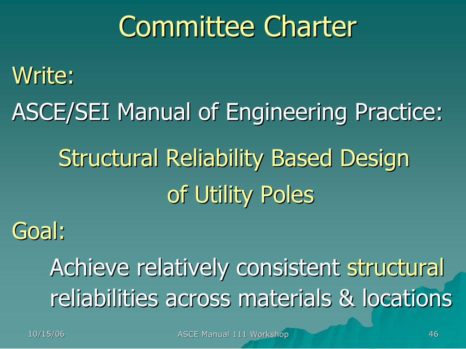
Committee Charter Committee Charter
Write: Write:
ASCE/SEI Manual of Engineering Practice: ASCE/SEI Manual of Engineering Practice:
Structural Reliability Based Design Structural Reliability Based Design
of Utility Poles of Utility Poles
Goal: Goal:
Achieve relatively consistent Achieve relatively consistent structural structural reliabilities across materials & locations reliabilities across materials & locations
10/15/06 10/15/06 ASCE Manual 111 Workshop ASCE Manual 111 Workshop 47 47
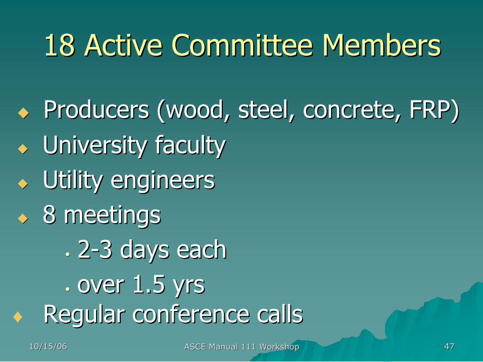
18 Active Committee Members 18 Active Committee Members
u u Producers (wood, steel, concrete, FRP) Producers (wood, steel, concrete, FRP) u u University faculty University faculty u u Utility engineers Utility engineers u u 8 meetings 8 meetings
• • 2 2 3 days each 3 days each • • over 1.5 yrs over 1.5 yrs
♦ Regular conference calls Regular conference calls

10/15/06 10/15/06 ASCE Manual 111 Workshop ASCE Manual 111 Workshop 48 48
Official Committee Roster (27) Official Committee Roster (27) Aichinger, Richard Valmont Industries Bingel, Nelson Osmose, Inc. Bowles, Gary Electrical Consultants
Brewer, William A. Rochester Gas and Electric Co.
Costa, Richard National Grid Dagher, Habib UMaine Davidson, James Shakespeare Slavin, Larry OCS Fouad, Fouad U of Alabama Birm. Garcia, Michael C. Tampa Electric Co. Goodwin, Tip Entergy Gromala, David Weyerhaeuser Ishac, Magdi Hydro 1 Networks Inc.
Lacoursiere, Brian IUSI Martirossian, Robert PEPCO Moritz, Terence Arizona Public Service Co.
Oliphant, Wes Newmark International, Inc.
Randle, Ron EDM Rollins, Martin H. M. Rollins Rubeiz, Camile AISI Snyder, Dan AISI Vandergriend, Larry Hughes Brothers Voda, Michael Salt River Project West, David Duke Energy Wolfe, Ron Forest Products Lab Wong, Jerry Florida Power & Light Zolotoochin, Alec BC Hydro
10/15/06 10/15/06 ASCE Manual 111 Workshop ASCE Manual 111 Workshop 49 49
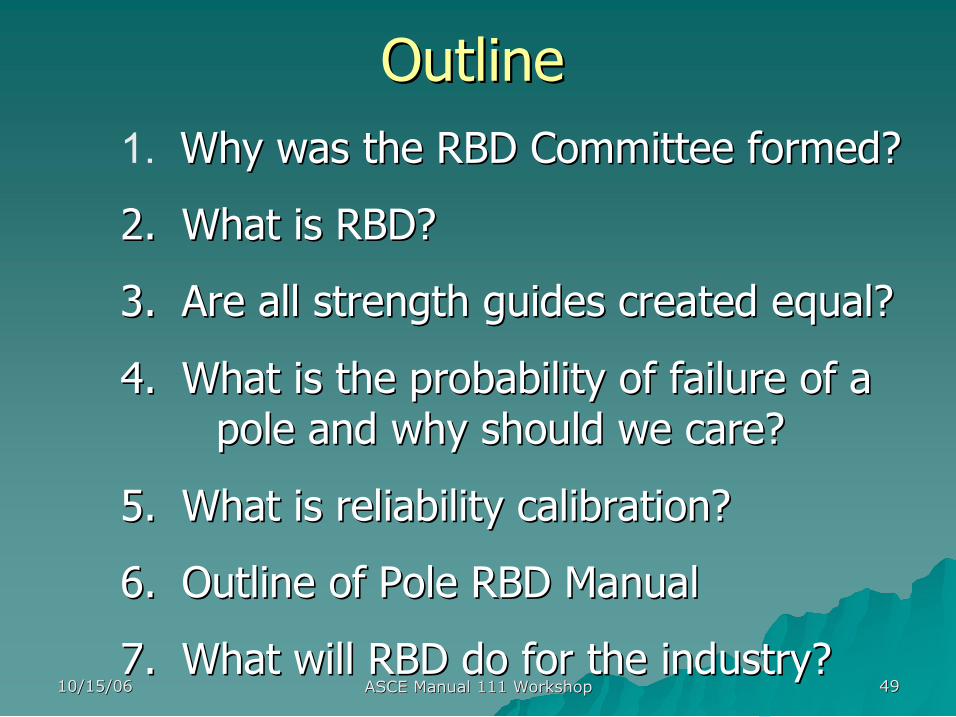
Outline Outline 1. Why was the RBD Committee formed? Why was the RBD Committee formed?
2. 2. What is RBD? What is RBD?
3. 3. Are all strength guides created equal? Are all strength guides created equal?
4. 4. What is the probability of failure of a What is the probability of failure of a pole and why should we care? pole and why should we care?
5. 5. What is reliability calibration? What is reliability calibration?
6. 6. Outline of Pole RBD Manual Outline of Pole RBD Manual
7. 7. What will RBD do for the industry? What will RBD do for the industry?
10/15/06 10/15/06 ASCE Manual 111 Workshop ASCE Manual 111 Workshop 50 50
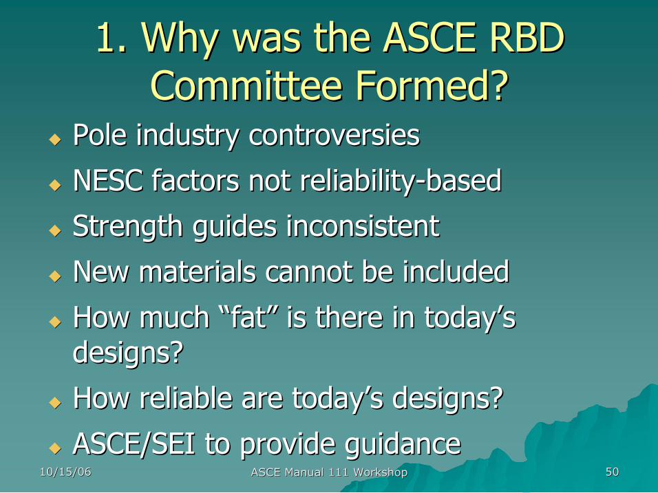
1. Why was the ASCE RBD 1. Why was the ASCE RBD Committee Formed? Committee Formed?
u u Pole industry controversies Pole industry controversies
u u NESC factors not reliability NESC factors not reliability based based
u u Strength guides inconsistent Strength guides inconsistent
u u New materials cannot be included New materials cannot be included
u u How much How much “ “fat fat” ” is there in today is there in today’ ’s s designs? designs?
u u How reliable are today How reliable are today’ ’s designs? s designs?
u u ASCE/SEI to provide guidance ASCE/SEI to provide guidance
10/15/06 10/15/06 ASCE Manual 111 Workshop ASCE Manual 111 Workshop 51 51
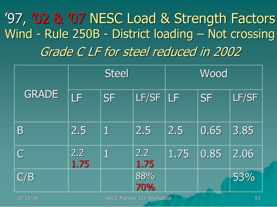
’ ’97 97, , ’ ’02 & 02 & ’ ’07 07 NESC Load & Strength Factors NESC Load & Strength Factors Wind Wind Rule 250B Rule 250B District loading District loading – – Not crossing Not crossing
Grade C LF for steel reduced in 2002 Grade C LF for steel reduced in 2002
53% 53% 88% 88% 70% 70%
C/B C/B
2.06 2.06 0.85 0.85 1.75 1.75 2.2 2.2 1.75 1.75
1 1 2.2 2.2 1.75 1.75
C C
3.85 3.85 0.65 0.65 2.5 2.5 2.5 2.5 1 1 2.5 2.5 B B
LF/SF LF/SF SF SF LF LF LF/SF LF/SF SF SF LF LF
Wood Wood Steel Steel
GRADE GRADE
10/15/06 10/15/06 ASCE Manual 111 Workshop ASCE Manual 111 Workshop 52 52
2. What is Reliability 2. What is Reliability Based Based Design (RBD)? Design (RBD)?
u u Each pole has a probability of failure Each pole has a probability of failure u u RBD gives consistent target reliability RBD gives consistent target reliability u u Uses multiple partial safety factors rather Uses multiple partial safety factors rather than one than one
u u Partial safety factors depend on load and Partial safety factors depend on load and strength statistics & target reliability strength statistics & target reliability
10/15/06 10/15/06 ASCE Manual 111 Workshop ASCE Manual 111 Workshop 53 53
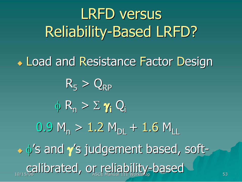
LRFD versus LRFD versus Reliability Reliability Based LRFD? Based LRFD?
u u L Load and oad and R Resistance esistance F Factor actor D Design esign
R R 5 5 > Q > Q RP RP
φ φ R R n n > > Σ Σ γ γ i i Q Q i i
0.9 0.9 M M n n > > 1.2 1.2 M M DL DL + + 1.6 1.6 M M LL LL
u u φ φ’ ’s and s and γ’ ’s judgement based, soft s judgement based, soft
calibrated, or reliability calibrated, or reliability based based

10/15/06 10/15/06 ASCE Manual 111 Workshop ASCE Manual 111 Workshop 54 54
Is it Harder to Design with RBD? Is it Harder to Design with RBD?
u u No, you won No, you won’ ’t need a Ph.D. in statistics! t need a Ph.D. in statistics!
u u Everyday design effort will be the same Everyday design effort will be the same
u u We have done all the hard work: We have done all the hard work:
The ASCE Manual will provide load and The ASCE Manual will provide load and
strength factors strength factors

10/15/06 10/15/06 ASCE Manual 111 Workshop ASCE Manual 111 Workshop 55 55
Will RBD Require More Will RBD Require More Expensive Poles? Expensive Poles?
u u No, on the average, designs will be No, on the average, designs will be
equivalent to NESC grades B and C equivalent to NESC grades B and C
10/15/06 10/15/06 ASCE Manual 111 Workshop ASCE Manual 111 Workshop 56 56
Manual 72 for steel poles Manual 72 for steel poles
PCI guide for P/C poles PCI guide for P/C poles ANSI 05.1 for wood poles ANSI 05.1 for wood poles
…… ……
3. Are all Strength Guides Created 3. Are all Strength Guides Created Equal? Equal?
10/15/06 10/15/06 ASCE Manual 111 Workshop ASCE Manual 111 Workshop 57 57
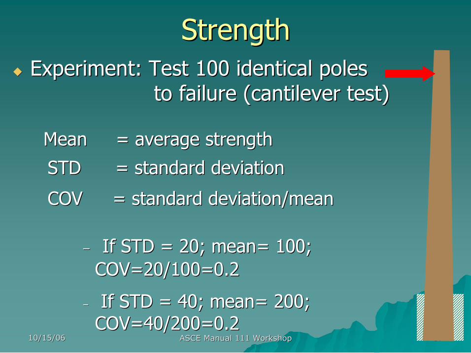
Strength Strength u u Experiment: Test 100 identical poles Experiment: Test 100 identical poles
to failure (cantilever test) to failure (cantilever test)
Mean = average strength Mean = average strength
STD = standard deviation STD = standard deviation
COV COV = standard deviation/mean = standard deviation/mean
– – If STD = 20; mean= 100; If STD = 20; mean= 100; COV=20/100=0.2 COV=20/100=0.2
– – If STD = 40; mean= 200; If STD = 40; mean= 200; COV=40/200=0.2 COV=40/200=0.2
10/15/06 10/15/06 ASCE Manual 111 Workshop ASCE Manual 111 Workshop 58 58
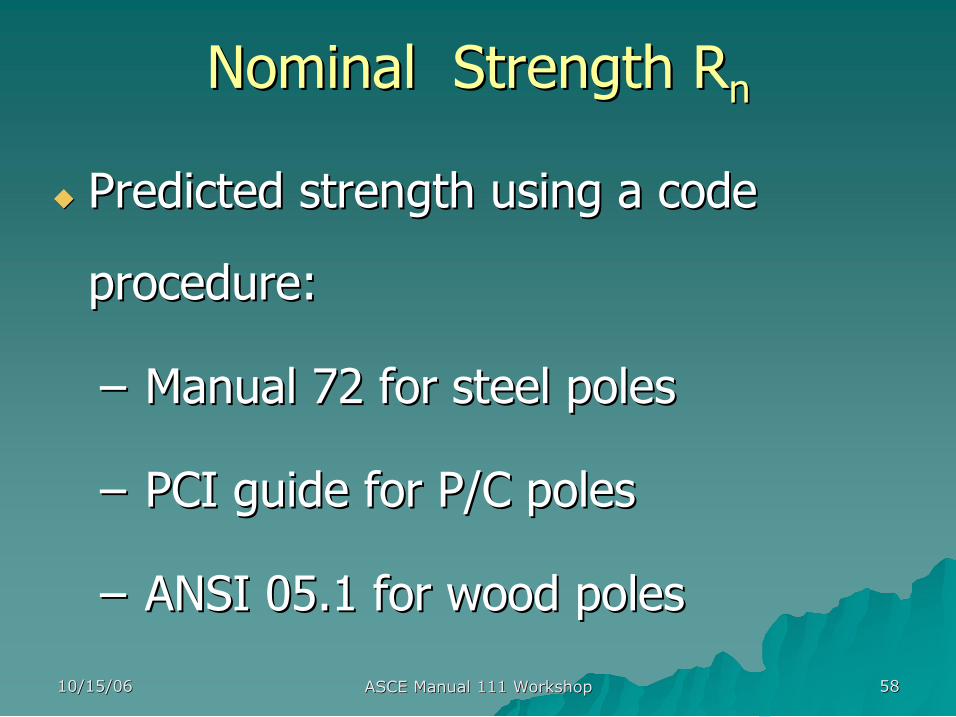
Nominal Strength Nominal Strength R R n n
u u Predicted strength using a code Predicted strength using a code
procedure: procedure:
– – Manual 72 for steel poles Manual 72 for steel poles
– – PCI guide for P/C poles PCI guide for P/C poles
– – ANSI 05.1 for wood poles ANSI 05.1 for wood poles
10/15/06 10/15/06 ASCE Manual 111 Workshop ASCE Manual 111 Workshop 59 59
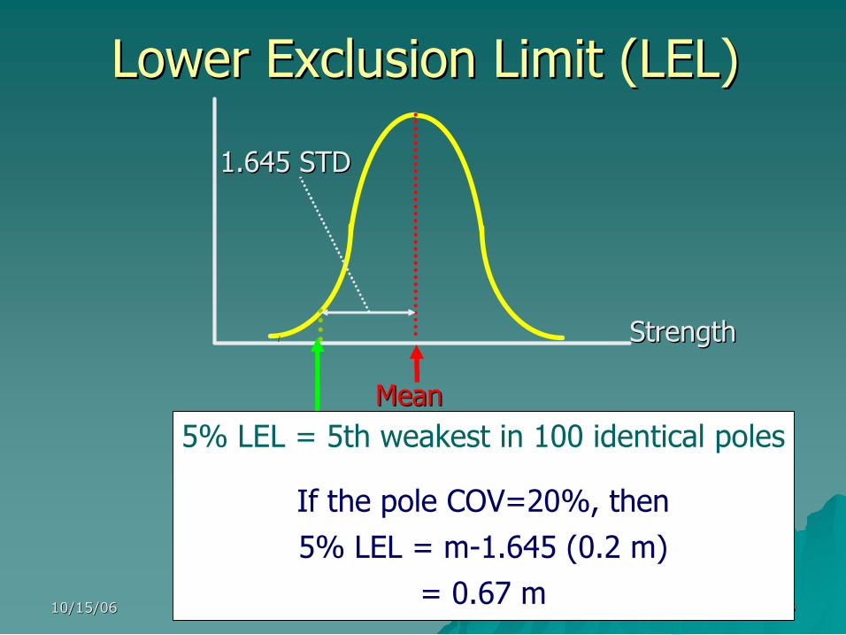
Lower Exclusion Limit (LEL) Lower Exclusion Limit (LEL)
1.645 STD 1.645 STD
5% LEL = 5th weakest in 100 identical poles
If the pole COV=20%, then 5% LEL = m1.645 (0.2 m)
= 0.67 m
Strength Strength
Mean Mean
10/15/06 10/15/06 ASCE Manual 111 Workshop ASCE Manual 111 Workshop 60 60
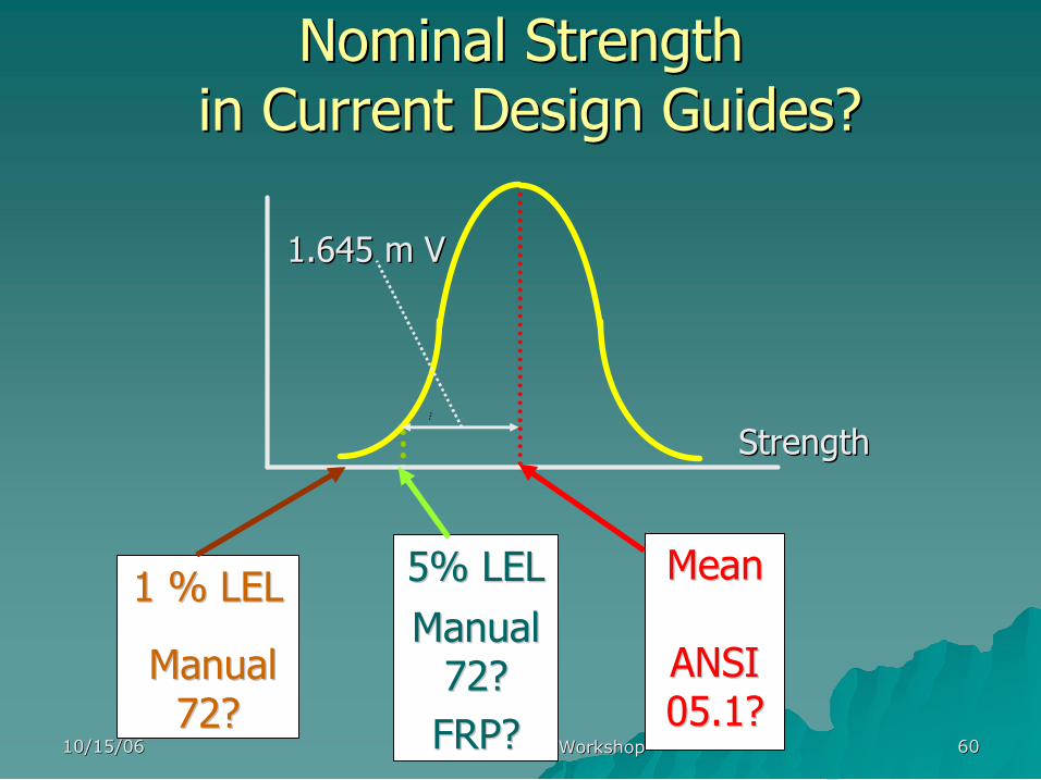
Nominal Strength Nominal Strength in Current Design Guides? in Current Design Guides?
1.645 m V 1.645 m V
5% LEL 5% LEL Manual Manual 72? 72? FRP? FRP?
Mean Mean
ANSI ANSI 05.1? 05.1?
1 % LEL 1 % LEL
Manual Manual 72? 72?
Strength Strength
10/15/06 10/15/06 ASCE Manual 111 Workshop ASCE Manual 111 Workshop 61 61
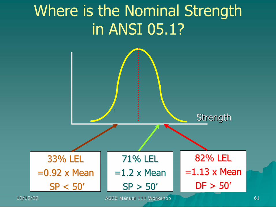
Where is the Nominal Strength in ANSI 05.1?
Strength Strength
71% LEL 71% LEL =1.2 x Mean =1.2 x Mean SP > 50 SP > 50’ ’
82% LEL 82% LEL =1.13 x Mean =1.13 x Mean DF > 50 DF > 50’ ’
33% LEL 33% LEL =0.92 x Mean =0.92 x Mean SP < 50 SP < 50’ ’
10/15/06 10/15/06 ASCE Manual 111 Workshop ASCE Manual 111 Workshop 62 62
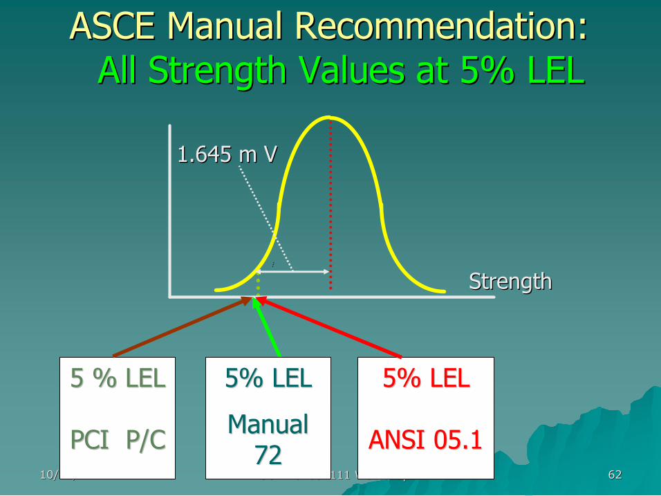
ASCE Manual Recommendation: ASCE Manual Recommendation: All Strength Values at 5% LEL All Strength Values at 5% LEL
Strength Strength
1.645 m V 1.645 m V
5% LEL 5% LEL
Manual Manual 72 72
5% LEL 5% LEL
ANSI 05.1 ANSI 05.1
5 % LEL 5 % LEL
PCI P/C PCI P/C
10/15/06 10/15/06 ASCE Manual 111 Workshop ASCE Manual 111 Workshop 63 63
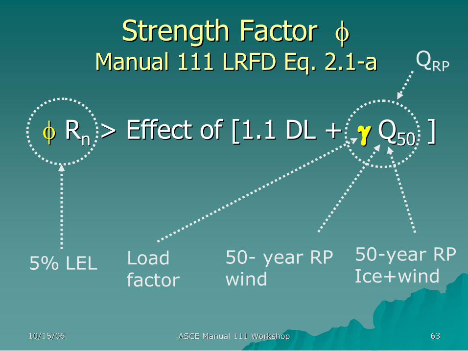
Strength Factor Strength Factor φ φ Manual 111 LRFD Manual 111 LRFD Eq Eq. 2.1 . 2.1 a a
φ φ R R n n > Effect of [1.1 DL + > Effect of [1.1 DL + γ γ Q Q 50 50 ] ]
50 year RP wind
50year RP Ice+wind
Load factor
5% LEL
Q RP

10/15/06 10/15/06 ASCE Manual 111 Workshop ASCE Manual 111 Workshop 64 64
Strength factor Strength factor φ φ
Nominal Nominal Strength Strength Exclusion Exclusion limit , e(%) limit , e(%)
COV COV R R
0.05 0.05 0.1 0.1 0.2 0.2
1.01 1.01 0.97 0.97 0.96 0.96 0.94 0.94 0.92 0.92 0.90 0.90 0.87 0.87
1.16 1.16 1.07 1.07 1.04 1.04 1.00 1.00 0.96 0.96 0.92 0.92 0.85 0.85
1.44 1.44 1.23 1.23 1.17 1.17 1.08 1.08 1.00 1.00 0.92 0.92 0.78 0.78
1.71 1.71 1.37 1.37 1.26 1.26 1.12 1.12 1.01 1.01 .89 .89 .69 .69
0.3 0.3
0.1 0.11 1 2 2 5 5 10 1020 2050 50
10/15/06 10/15/06 ASCE Manual 111 Workshop ASCE Manual 111 Workshop 65 65
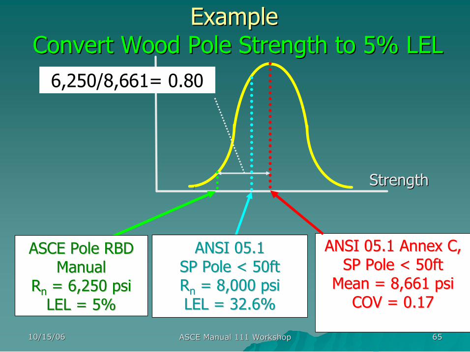
Example Example Convert Wood Pole Strength to 5% LEL Convert Wood Pole Strength to 5% LEL
Strength Strength
ANSI 05.1 Annex C, ANSI 05.1 Annex C, SP Pole < 50ft SP Pole < 50ft Mean = 8,661 Mean = 8,661 psi psi COV = 0.17 COV = 0.17
ASCE Pole RBD ASCE Pole RBD Manual Manual
R R n n = 6,250 = 6,250 psi psi LEL = 5% LEL = 5%
6,250/8,661= 0.80
ANSI 05.1 ANSI 05.1 SP Pole < 50ft SP Pole < 50ft R R n n = 8,000 = 8,000 psi psi LEL = 32.6% LEL = 32.6%
10/15/06 10/15/06 ASCE Manual 111 Workshop ASCE Manual 111 Workshop 66 66
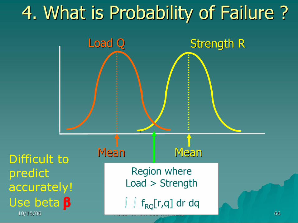
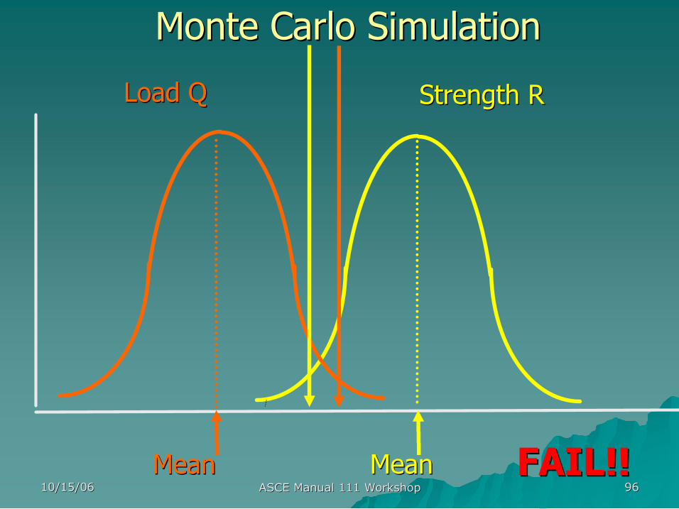
4. What is Probability of Failure ? 4. What is Probability of Failure ?
Region where Load > Strength
∫ ∫ f RQ [r,q] dr dq
Strength R Strength R
Mean Mean
Load Q Load Q
Mean Mean Difficult to predict accurately! Use beta β
10/15/06 10/15/06 ASCE Manual 111 Workshop ASCE Manual 111 Workshop 67 67
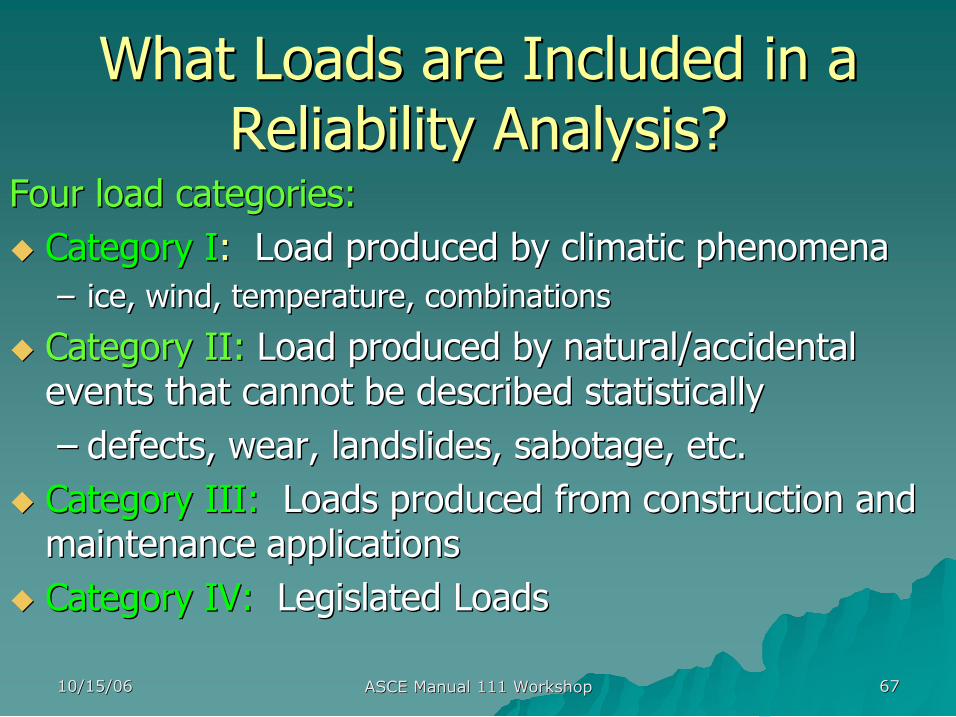
What Loads are Included in a What Loads are Included in a Reliability Analysis? Reliability Analysis?
Four load categories: Four load categories: u u Category I Category I: : Load produced by climatic phenomena Load produced by climatic phenomena
– – ice, wind, temperature, combinations ice, wind, temperature, combinations
u u Category II: Category II: Load produced by natural/accidental Load produced by natural/accidental events that cannot be described statistically events that cannot be described statistically – – defects, wear, landslides, sabotage, etc. defects, wear, landslides, sabotage, etc.
u u Category III: Category III: Loads produced from construction and Loads produced from construction and maintenance maintenance applications applications
u u Category IV: Category IV: Legislated Loads Legislated Loads
10/15/06 10/15/06 ASCE Manual 111 Workshop ASCE Manual 111 Workshop 68 68
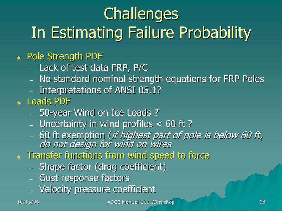
Challenges Challenges In Estimating Failure Probability In Estimating Failure Probability
u u Pole Strength PDF Pole Strength PDF – – Lack of test data FRP, P/C Lack of test data FRP, P/C – – No standard nominal strength equations for FRP Poles No standard nominal strength equations for FRP Poles – – Interpretations of ANSI 05.1? Interpretations of ANSI 05.1?
u u Loads PDF Loads PDF – – 50 50 year Wind on Ice Loads ? year Wind on Ice Loads ? – – Uncertainty in wind profiles < 60 ft ? Uncertainty in wind profiles < 60 ft ? – – 60 ft exemption ( 60 ft exemption (if highest part of pole is below 60 ft, if highest part of pole is below 60 ft, do not design for wind on wires do not design for wind on wires
u u Transfer functions from wind speed to force Transfer functions from wind speed to force – – Shape factor (drag coefficient) Shape factor (drag coefficient) – – Gust response factors Gust response factors – – Velocity pressure coefficient Velocity pressure coefficient
10/15/06 10/15/06 ASCE Manual 111 Workshop ASCE Manual 111 Workshop 69 69
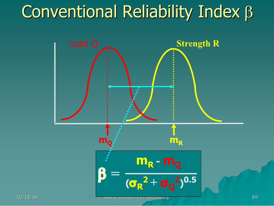
Conventional Reliability Index Conventional Reliability Index β β
Strength R
m R
Load Q
m Q
m R m Q (σ R 2 + σ Q 2 ) 0.5 β =
10/15/06 10/15/06 ASCE Manual 111 Workshop ASCE Manual 111 Workshop 70 70
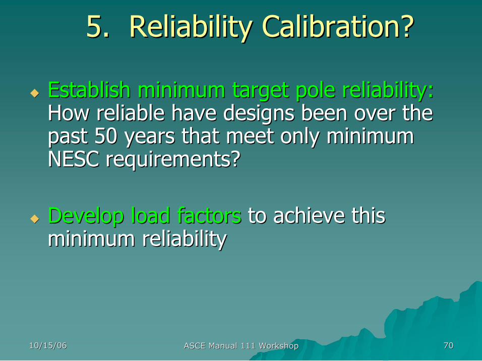
5. Reliability Calibration? 5. Reliability Calibration?
u u Establish minimum target pole reliability: Establish minimum target pole reliability: How reliable have designs been over the How reliable have designs been over the past 50 years that meet only minimum past 50 years that meet only minimum NESC requirements? NESC requirements?
u u Develop load factors Develop load factors to achieve this to achieve this minimum reliability minimum reliability
10/15/06 10/15/06 ASCE Manual 111 Workshop ASCE Manual 111 Workshop 71 71
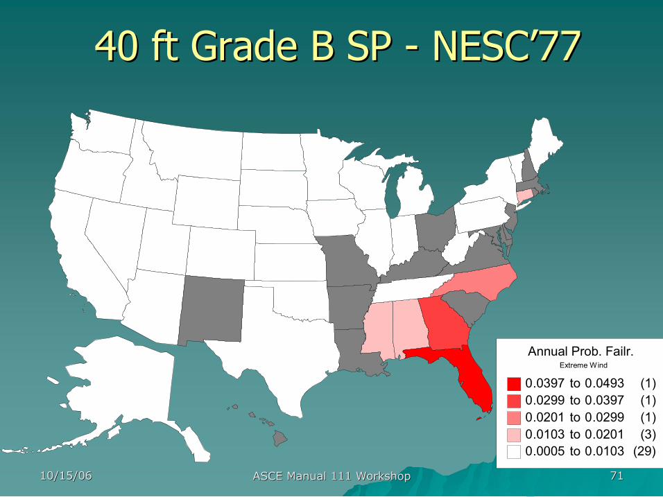
40 ft Grade B SP 40 ft Grade B SP NESC NESC’ ’77 77
Annual Prob. Failr. Extreme Wind
0.0397 to 0.0493 (1) 0.0299 to 0.0397 (1) 0.0201 to 0.0299 (1) 0.0103 to 0.0201 (3) 0.0005 to 0.0103 (29)
10/15/06 10/15/06 ASCE Manual 111 Workshop ASCE Manual 111 Workshop 72 72
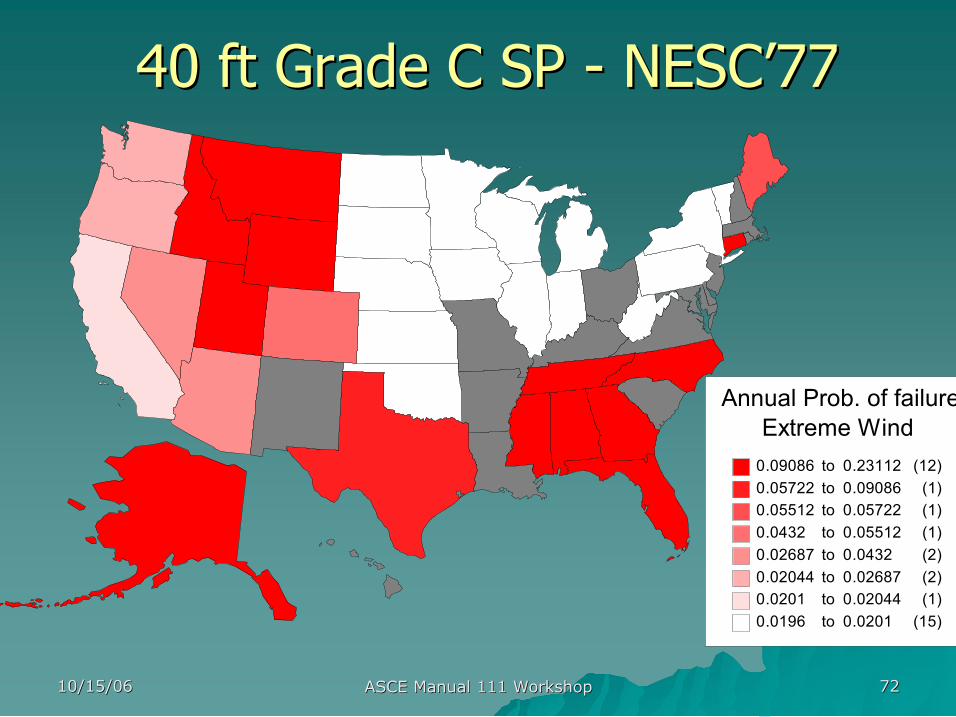
40 ft Grade C SP 40 ft Grade C SP NESC NESC’ ’77 77
Annual Prob. of failure Extreme Wind 0.09086 to 0.23112 (12) 0.05722 to 0.09086 (1) 0.05512 to 0.05722 (1) 0.0432 to 0.05512 (1) 0.02687 to 0.0432 (2) 0.02044 to 0.02687 (2) 0.0201 to 0.02044 (1) 0.0196 to 0.0201 (15)
10/15/06 10/15/06 ASCE Manual 111 Workshop ASCE Manual 111 Workshop 73 73
How Were Calibration How Were Calibration Results Used? Results Used?
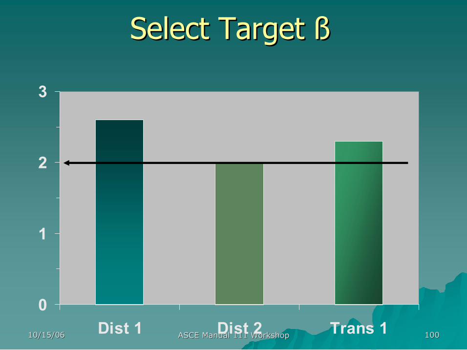
u u Selecting target betas Selecting target betas
– – Grade B, Grade C Grade B, Grade C
u u What have we learned from the reliability What have we learned from the reliability
calibrations? calibrations?
– – Does reliability change geographically? Does reliability change geographically?
– – How reliable is Grade B versus C? How reliable is Grade B versus C?
– – What does the 60 ft exemption really do? What does the 60 ft exemption really do?
10/15/06 10/15/06 ASCE Manual 111 Workshop ASCE Manual 111 Workshop 74 74
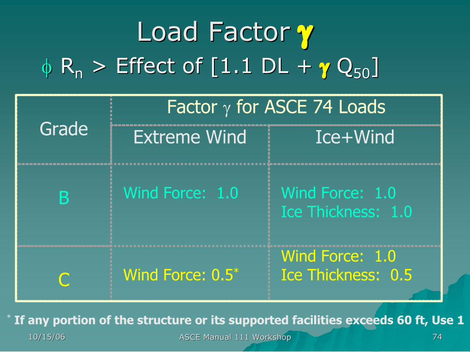
Grade Factor γ for ASCE 74 Loads
Extreme Wind Ice+Wind
B Wind Force: 1.0 Wind Force: 1.0 Ice Thickness: 1.0
C Wind Force: 0.5 * Wind Force: 1.0 Ice Thickness: 0.5
* If any portion of the structure or its supported facilities exceeds 60 ft, Use 1
Load Factor Load Factor γ γ φ φ R R n n > Effect of [1.1 DL + > Effect of [1.1 DL + γ γ Q Q 50 50 ] ]
10/15/06 10/15/06 ASCE Manual 111 Workshop ASCE Manual 111 Workshop 75 75
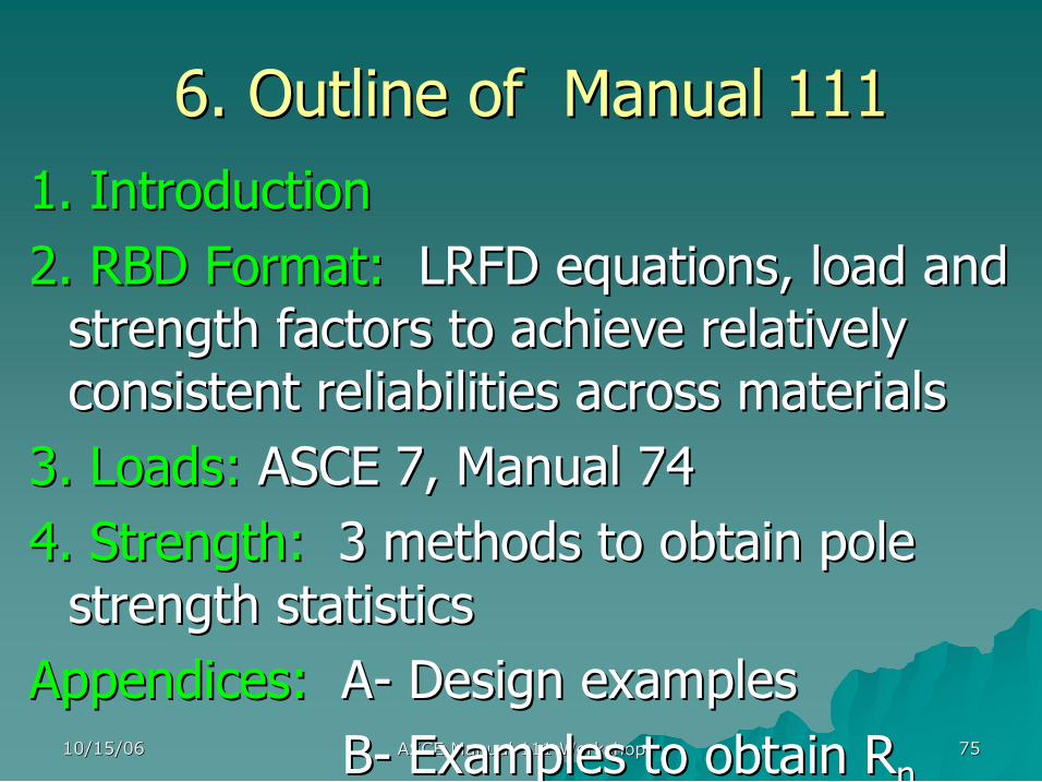
6. Outline of Manual 111 6. Outline of Manual 111 1. Introduction 1. Introduction 2. RBD Format: 2. RBD Format: LRFD equations, load and LRFD equations, load and strength factors to achieve relatively strength factors to achieve relatively consistent reliabilities across materials consistent reliabilities across materials
3. Loads: 3. Loads: ASCE 7, Manual 74 ASCE 7, Manual 74 4. Strength: 4. Strength: 3 methods to obtain pole 3 methods to obtain pole strength statistics strength statistics
Appendices: Appendices: A A Design examples Design examples B B Examples to obtain Examples to obtain R R n n

10/15/06 10/15/06 ASCE Manual 111 Workshop ASCE Manual 111 Workshop 76 76
7. What will RBD do for the 7. What will RBD do for the
Industry? Industry?
10/15/06 10/15/06 ASCE Manual 111 Workshop ASCE Manual 111 Workshop 77 77
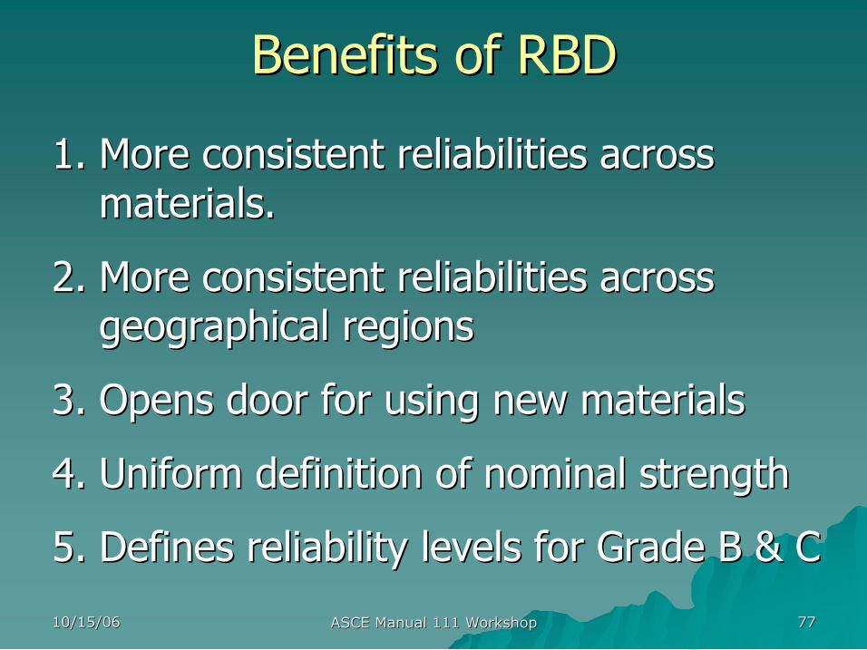
Benefits of RBD Benefits of RBD
1. 1. More consistent reliabilities across More consistent reliabilities across materials. materials.
2. 2. More consistent reliabilities across More consistent reliabilities across geographical regions geographical regions
3. 3. Opens door for using new materials Opens door for using new materials
4. 4. Uniform definition of nominal strength Uniform definition of nominal strength
5. 5. Defines reliability levels for Grade B & C Defines reliability levels for Grade B & C
10/15/06 10/15/06 ASCE Manual 111 Workshop ASCE Manual 111 Workshop 78 78
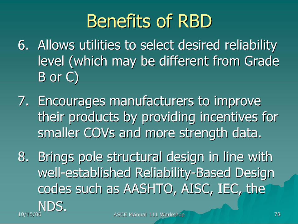
Benefits of RBD Benefits of RBD 6. 6. Allows utilities to select desired reliability Allows utilities to select desired reliability
level (which may be different from Grade level (which may be different from Grade B or C) B or C)
7. 7. Encourages manufacturers to improve Encourages manufacturers to improve their products by providing incentives for their products by providing incentives for smaller smaller COVs COVs and more strength data. and more strength data.
8. 8. Brings pole structural design in line with Brings pole structural design in line with well well established Reliability established Reliability Based Design Based Design codes such as AASHTO, AISC, IEC, the codes such as AASHTO, AISC, IEC, the NDS. NDS.
10/15/06 10/15/06 ASCE Manual 111 Workshop ASCE Manual 111 Workshop 79 79
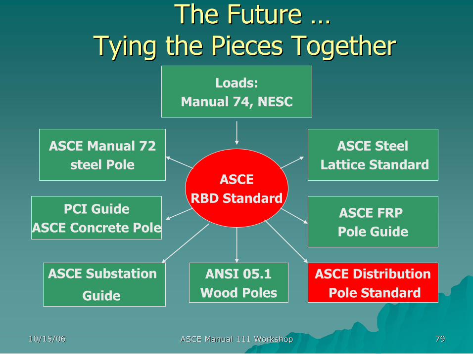
The Future The Future … … Tying the Pieces Together Tying the Pieces Together
Loads: Manual 74, NESC
ASCE RBD Standard
ASCE Manual 72 steel Pole
ASCE Steel Lattice Standard
PCI Guide ASCE Concrete Pole
ASCE FRP Pole Guide
ASCE Substation
Guide
ASCE Distribution Pole Standard
ANSI 05.1 Wood Poles

10/15/06 10/15/06 ASCE Manual 111 Workshop ASCE Manual 111 Workshop 80 80
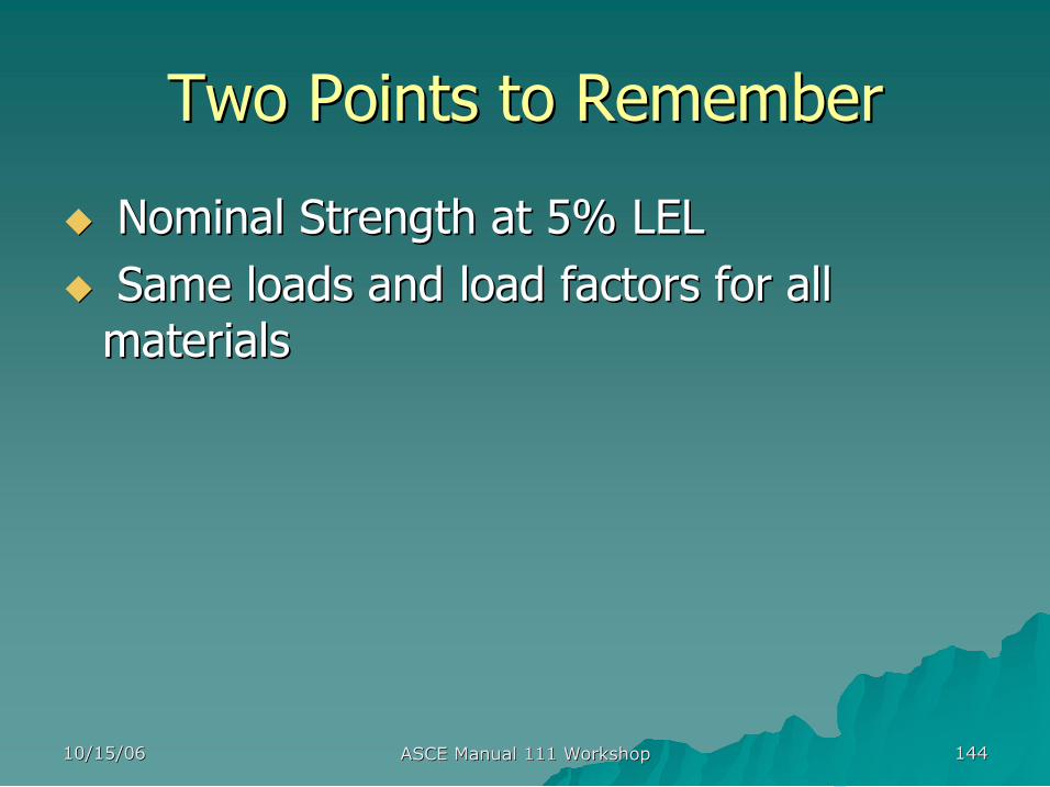
Two Points to Remember Two Points to Remember
u u Nominal Strength at 5% LEL Nominal Strength at 5% LEL u u Same loads and load factors for all Same loads and load factors for all materials materials

10/15/06 10/15/06 ASCE Manual 111 Workshop ASCE Manual 111 Workshop 81 81
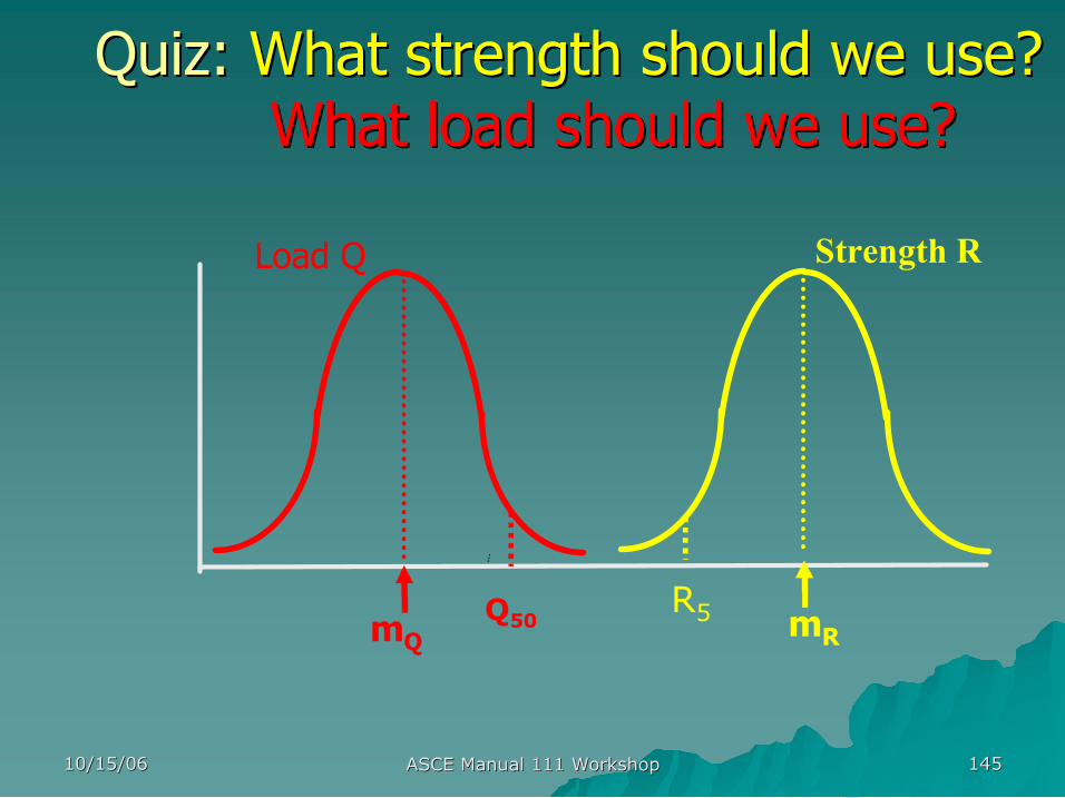
Quiz: Quiz: What strength should we use? What strength should we use? What load should we use? What load should we use?
Load Q
m Q Q 50
Strength R
m R R 5

10/15/06 10/15/06 ASCE Manual 111 Workshop ASCE Manual 111 Workshop 82 82
Quiz: How do we achieve relatively Quiz: How do we achieve relatively consistent reliability across consistent reliability across materials and locations? materials and locations? Load Q
m Q Q 50
Strength R
m R R 5
10/15/06 10/15/06 ASCE Manual 111 Workshop ASCE Manual 111 Workshop 83 83
Next Steps Next Steps ASCE Manual 111 Development ASCE Manual 111 Development
u u User feedback User feedback u u Start work on second edition in 2008 Start work on second edition in 2008
Calibration of Reliability Based Calibration of Reliability Based Design Method Design Method
Next:
presented by presented by
Michael Voda, P.E. Michael Voda, P.E. – – Principal Civil Engineer Principal Civil Engineer Salt River Project Salt River Project
10/15/06 10/15/06 ASCE Manual 111 Workshop ASCE Manual 111 Workshop 85 85
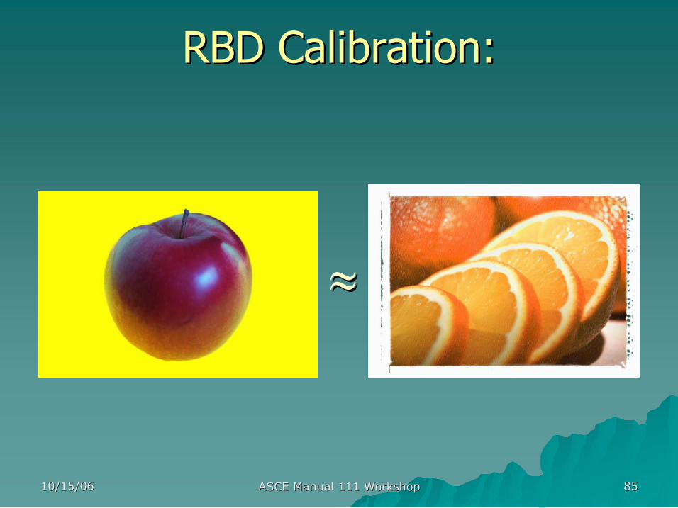
RBD Calibration: RBD Calibration:
RBD RBD ≈ ≈ NESC NESC
10/15/06 10/15/06 ASCE Manual 111 Workshop ASCE Manual 111 Workshop 86 86
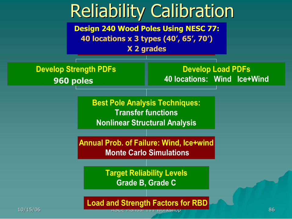
Reliability Calibration Reliability Calibration
Develop Strength PDFs 960 poles
Develop Load PDFs 40 locations: Wind Ice+Wind
Load and Strength Factors for RBD
Target Reliability Levels Grade B, Grade C
Annual Prob. of Failure: Wind, Ice+wind Monte Carlo Simulations
Best Pole Analysis Techniques: Transfer functions
Nonlinear Structural Analysis
Design 960 Poles Using NESC: 40 locations x 4 types (40', 65', 70', 110')
x 2 Grades x 3 Materials
Design 240 Wood Poles Using NESC 77: 40 locations x 3 types (40’, 65’, 70’)
X 2 grades
960 poles
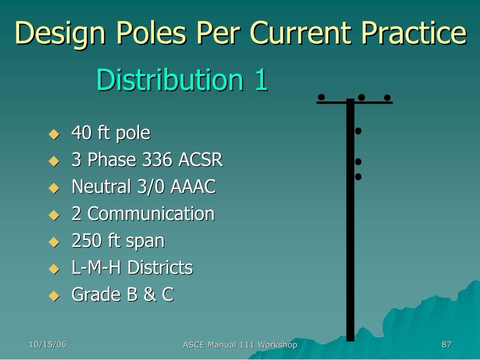
10/15/06 10/15/06 ASCE Manual 111 Workshop ASCE Manual 111 Workshop 87 87
Distribution 1 Distribution 1
u u 40 ft pole 40 ft pole u u 3 Phase 336 ACSR 3 Phase 336 ACSR u u Neutral 3/0 AAAC Neutral 3/0 AAAC u u 2 Communication 2 Communication u u 250 ft span 250 ft span u u L L M M H Districts H Districts u u Grade B & C Grade B & C
Design Poles Per Current Practice Design Poles Per Current Practice
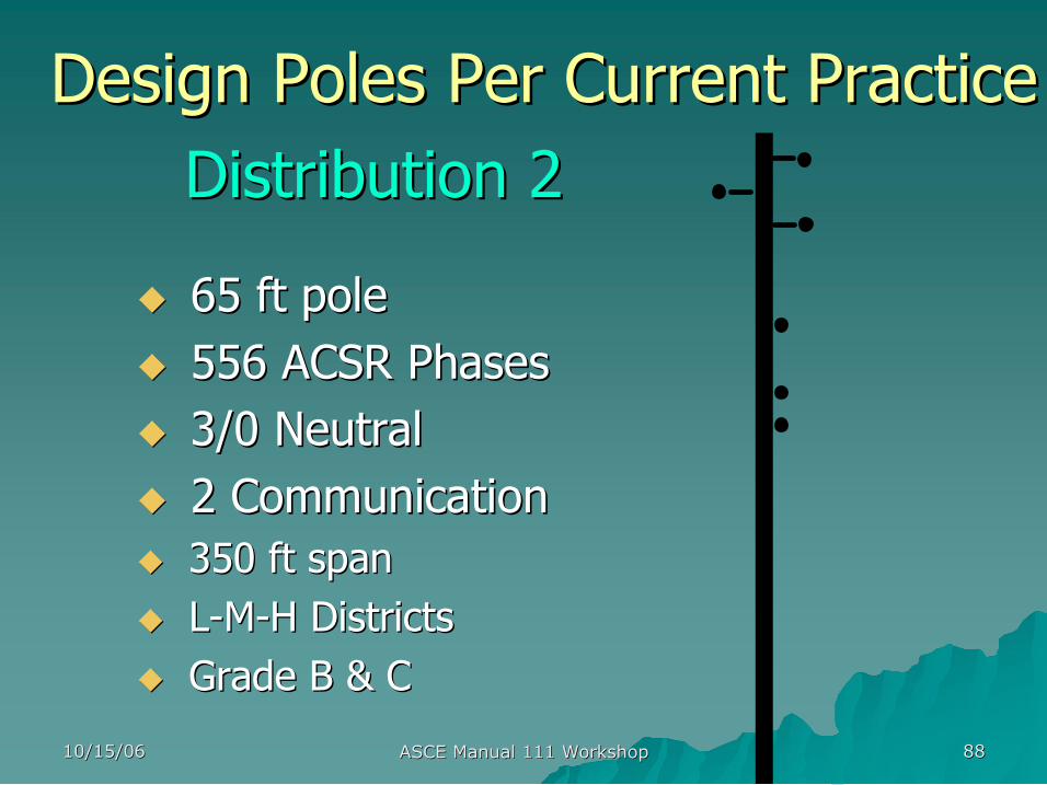
10/15/06 10/15/06 ASCE Manual 111 Workshop ASCE Manual 111 Workshop 88 88
Distribution 2 Distribution 2
u u 65 ft pole 65 ft pole u u 556 ACSR Phases 556 ACSR Phases u u 3/0 Neutral 3/0 Neutral u u 2 Communication 2 Communication u u 350 ft span 350 ft span u u L L M M H Districts H Districts u u Grade B & C Grade B & C
Design Poles Per Current Practice Design Poles Per Current Practice
10/15/06 10/15/06 ASCE Manual 111 Workshop ASCE Manual 111 Workshop 89 89
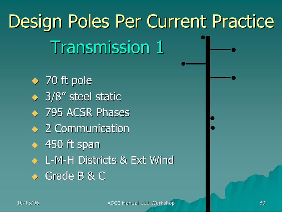
Transmission 1 Transmission 1
u u 70 ft pole 70 ft pole u u 3/8 3/8” ” steel static steel static u u 795 ACSR Phases 795 ACSR Phases u u 2 Communication 2 Communication u u 450 ft span 450 ft span u u L L M M H Districts & Ext Wind H Districts & Ext Wind u u Grade B & C Grade B & C
Design Poles Per Current Practice Design Poles Per Current Practice
10/15/06 10/15/06 ASCE Manual 111 Workshop ASCE Manual 111 Workshop 90 90
Design Poles Per Current Practice Design Poles Per Current Practice NESC 1977: Grade C NESC 1977: Grade C
Pole Class: Load District
Light Medium Heavy
Dist 1 40ft 4 6 5
Dist 2 65ft 2 4 3
Trans 1 70ft 1 3 2

10/15/06 10/15/06 ASCE Manual 111 Workshop ASCE Manual 111 Workshop 91 91
Design Poles Per Current Practice Design Poles Per Current Practice NESC 1977: Grade B NESC 1977: Grade B
Pole Class: Load District
Light Medium Heavy
Dist 1 40ft 1 3 2
Dist 2 65ft H2 1 H1
Trans 1 70ft H4 H1 H3
10/15/06 10/15/06 ASCE Manual 111 Workshop ASCE Manual 111 Workshop 92 92
Strength PDF Strength PDF ANSI 05.1 2002 ANSI 05.1 2002
§ § Dist 1 Dist 1 SYP 40ft poles SYP 40ft poles mean = mean = 8000 psi COV= 0.20
§ § Dist 2 Dist 2 SYP 65ft poles SYP 65ft poles mean = mean = 8000 psi COV = 0.20
§ § Trans 1 Trans 1 DF 70ft poles DF 70ft poles mean = mean = 8000 psi COV = 0.20
§ § Normal Distribution Normal Distribution used for Fiber Strength used for Fiber Strength

10/15/06 10/15/06 ASCE Manual 111 Workshop ASCE Manual 111 Workshop 93 93
Load PDF Load PDF
u u Wind Wind Extreme Type I Distribution Extreme Type I Distribution ( (Peterka Peterka, , 1998). One PDF for Continental US and 1998). One PDF for Continental US and another for Hurricane zones. another for Hurricane zones.
u u Ice with concurrent wind Ice with concurrent wind Modified Pareto Distribution Modified Pareto Distribution (Jones) (Jones)
10/15/06 10/15/06 ASCE Manual 111 Workshop ASCE Manual 111 Workshop 94 94
u u Monte Carlo Simulation Monte Carlo Simulation
u u 200,000 simulations per pole per location 200,000 simulations per pole per location
u u Results = Results = Annual Probability of Failure Annual Probability of Failure (P (P f f ) ) P Pf f = No. Failures/ No. Simulations = No. Failures/ No. Simulations
u u Relationship between Relationship between ß ß and Pf and Pf P P f f = =Ф Ф [ [ ß ß] ]
Calculate Annual Reliability ( Calculate Annual Reliability (ß ß) )
10/15/06 10/15/06 ASCE Manual 111 Workshop ASCE Manual 111 Workshop 95 95
Monte Carlo Simulation Monte Carlo Simulation
Strength R Strength R
Mean Mean
Load Q Load Q
Mean Mean PASS!! PASS!!
10/15/06 10/15/06 ASCE Manual 111 Workshop ASCE Manual 111 Workshop 96 96
Monte Carlo Simulation Monte Carlo Simulation
Strength R Strength R
Mean Mean
Load Q Load Q
Mean Mean FAIL!! FAIL!!

10/15/06 10/15/06 ASCE Manual 111 Workshop ASCE Manual 111 Workshop 97 97
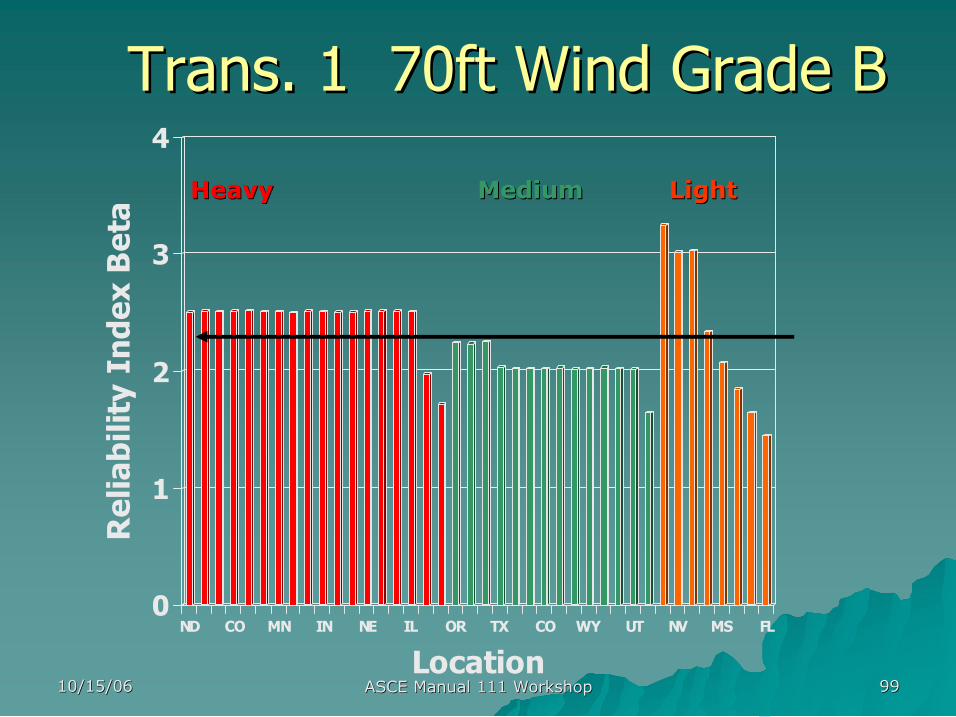
Dist. 1 40ft Wind Grade B Dist. 1 40ft Wind Grade B
0
1
2
3
4 Reliability Index Beta
ND CO MN IN NE IL OR TX CO WY UT NV MS FL
Location
Heavy Heavy Medium Medium Light Light
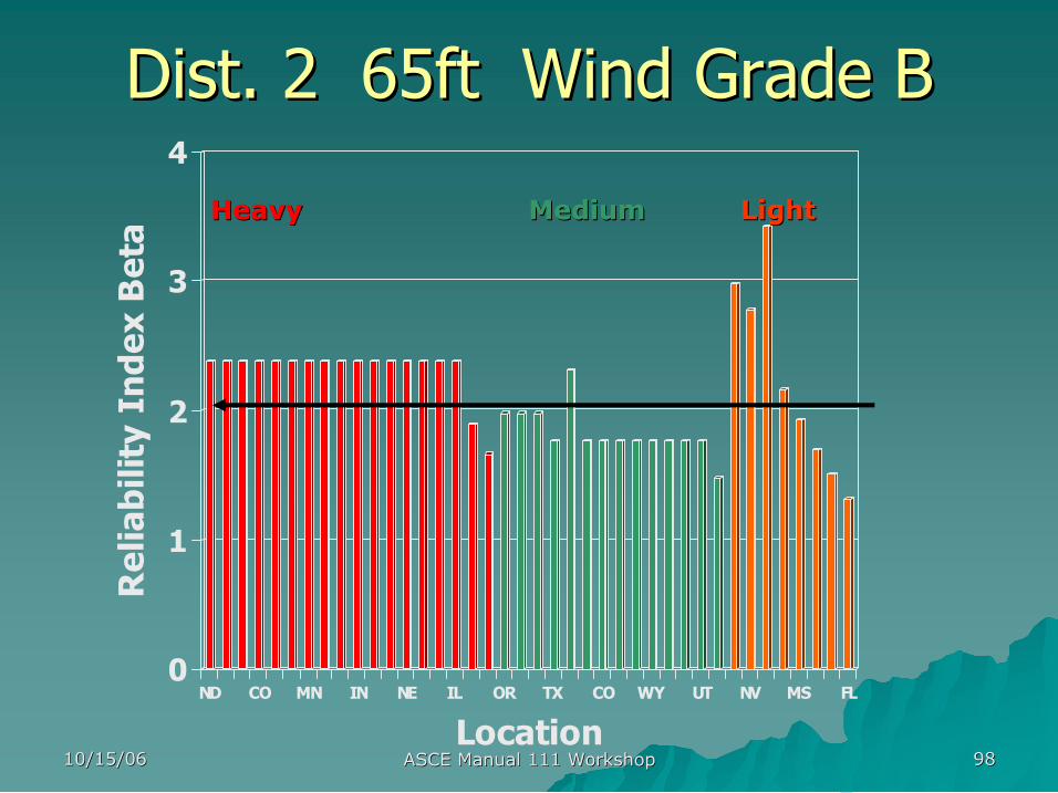
10/15/06 10/15/06 ASCE Manual 111 Workshop ASCE Manual 111 Workshop 98 98
Dist. 2 65ft Wind Grade B Dist. 2 65ft Wind Grade B
0
1
2
3
4 Reliability Index Beta
ND CO MN IN NE IL OR TX CO WY UT NV MS FL
Location
Heavy Heavy Medium Medium Light Light
10/15/06 10/15/06 ASCE Manual 111 Workshop ASCE Manual 111 Workshop 99 99
Trans. 1 70ft Wind Grade B Trans. 1 70ft Wind Grade B
0
1
2
3
4 Reliability Index Beta
ND CO MN IN NE IL OR TX CO WY UT NV MS FL
Location
Heavy Heavy Medium Medium Light Light
10/15/06 10/15/06 ASCE Manual 111 Workshop ASCE Manual 111 Workshop 100 100
Select Target Select Target ß ß
0
1
2
3
Dist 1 Dist 2 Trans 1
10/15/06 10/15/06 ASCE Manual 111 Workshop ASCE Manual 111 Workshop 101 101
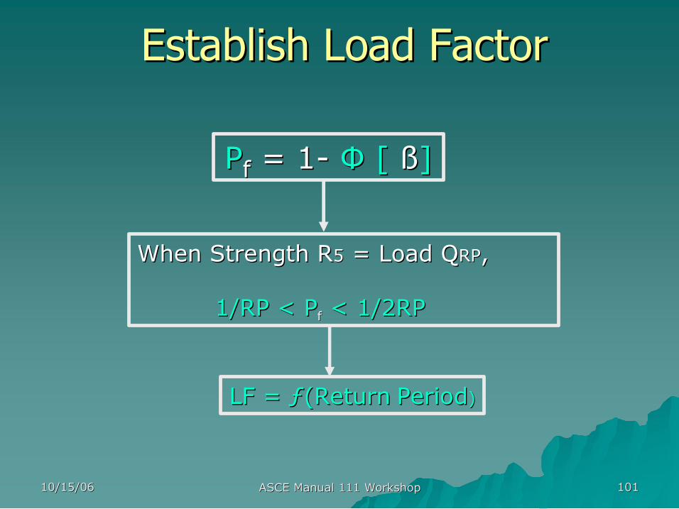
Establish Load Factor Establish Load Factor
P P f f = 1 = 1 Ф Ф [ [ ß ß] ]
When Strength R When Strength R5 5 = Load Q = Load QRP RP, ,
1/RP < 1/RP < P P f f < 1/2RP < 1/2RP
LF = LF = ƒ ƒ(Return (Return Period Period) )

10/15/06 10/15/06 ASCE Manual 111 Workshop ASCE Manual 111 Workshop 102 102
0.0
0.5
1.0
1.5
0 100 200 300 400
Return Period (yrs)
Load Factor
Return Period vs Load Factor Return Period vs Load Factor Extreme Type I Distribution Extreme Type I Distribution
50 50
1.0 1.0
10/15/06 10/15/06 ASCE Manual 111 Workshop ASCE Manual 111 Workshop 103 103
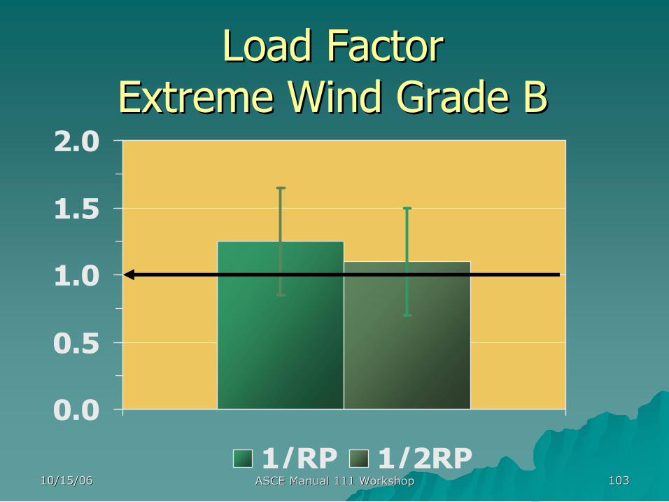
Load Factor Load Factor Extreme Wind Grade B Extreme Wind Grade B
0.0
0.5
1.0
1.5
2.0
1/RP 1/2RP
10/15/06 10/15/06 ASCE Manual 111 Workshop ASCE Manual 111 Workshop 104 104
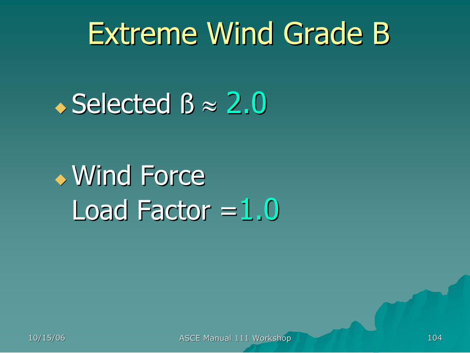
Extreme Wind Grade B Extreme Wind Grade B
u u Selected Selected ß ß ≈ ≈ 2.0 2.0
u u Wind Force Wind Force Load Factor = Load Factor =1.0 1.0
10/15/06 10/15/06 ASCE Manual 111 Workshop ASCE Manual 111 Workshop 105 105
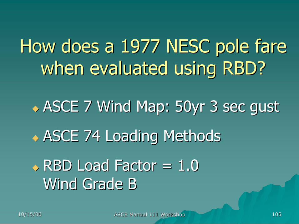
How does a 1977 NESC pole fare How does a 1977 NESC pole fare when evaluated using RBD? when evaluated using RBD?
u u ASCE 7 Wind Map: 50yr 3 sec gust ASCE 7 Wind Map: 50yr 3 sec gust
u u ASCE 74 Loading Methods ASCE 74 Loading Methods
u u RBD Load Factor = 1.0 RBD Load Factor = 1.0 Wind Grade B Wind Grade B
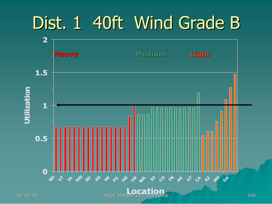
10/15/06 10/15/06 ASCE Manual 111 Workshop ASCE Manual 111 Workshop 106 106
Dist. 1 40ft Wind Grade B Dist. 1 40ft Wind Grade B
0
0.5
1
1.5
2
ND VT IA MN SD
MI NE PA ME OR WA ID
CO TN AK UT CA AZ MS GA
Location
Utilization
Heavy Heavy Medium Medium Light Light

10/15/06 10/15/06 ASCE Manual 111 Workshop ASCE Manual 111 Workshop 107 107
Dist. 2 65ft Wind Grade B Dist. 2 65ft Wind Grade B
0.0
0.5
1.0
1.5
2.0 Utilization
ND
CO
MN IN
NE
IL
OR
TX
CO
WY UT
NV
MS FL
Location
Heavy Heavy Medium Medium Light Light
10/15/06 10/15/06 ASCE Manual 111 Workshop ASCE Manual 111 Workshop 108 108
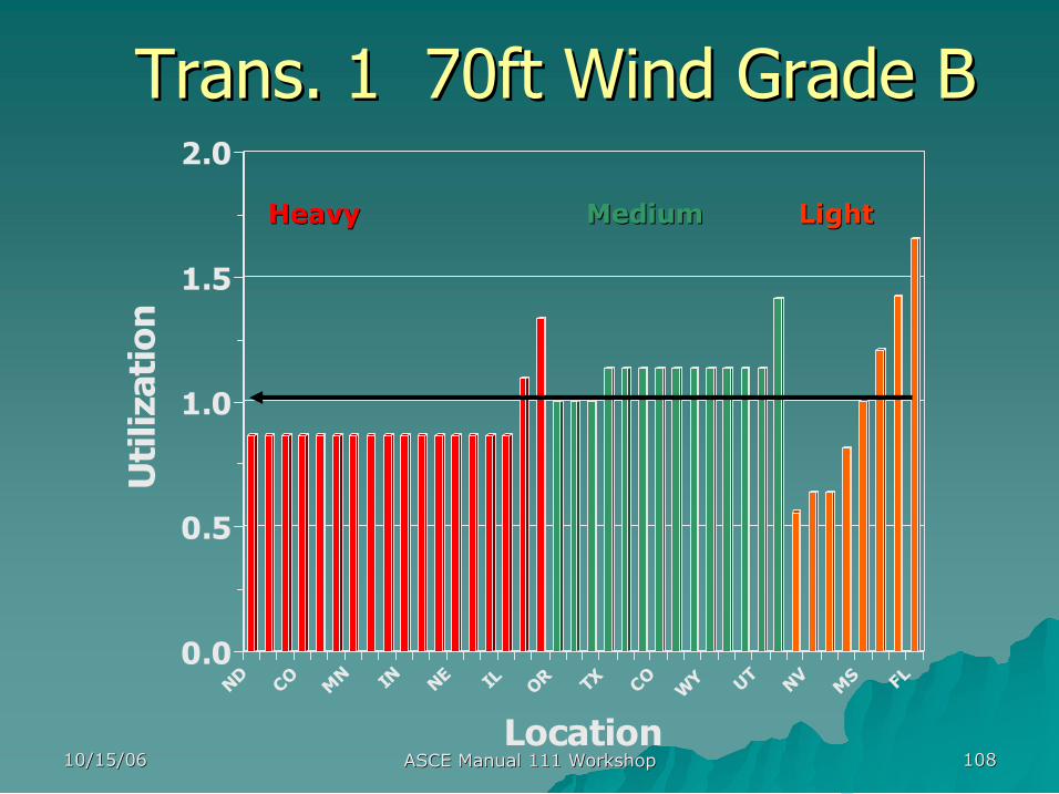
Trans. 1 70ft Wind Grade B Trans. 1 70ft Wind Grade B
0.0
0.5
1.0
1.5
2.0 Utilization
ND
CO
MN IN
NE
IL
OR
TX
CO WY UT
NV
MS FL
Location
Heavy Heavy Medium Medium Light Light
10/15/06 10/15/06 ASCE Manual 111 Workshop ASCE Manual 111 Workshop 109 109
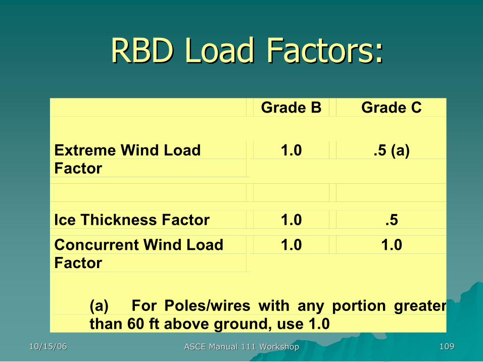
RBD Load Factors: RBD Load Factors: Grade B Grade C
Extreme Wind Load Factor
1.0 .5 (a)
Ice Thickness Factor 1.0 .5 Concurrent Wind Load Factor
1.0 1.0
(a) For Poles/wires with any portion greater than 60 ft above ground, use 1.0

Loads Loads
Next:
presented by presented by
Dr. Jerry Wong, P.E. Dr. Jerry Wong, P.E. – – Staff Engineer, Staff Engineer, Florida Power and Light Florida Power and Light
10/15/06 10/15/06 ASCE Manual 111 Workshop ASCE Manual 111 Workshop 111 111
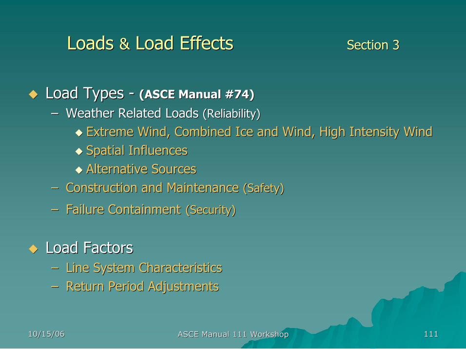
Loads Loads & & Load Effects Load Effects Section 3 Section 3
u u Load Types Load Types (ASCE Manual #74) (ASCE Manual #74)
– – Weather Related Loads Weather Related Loads (Reliability) (Reliability)
u u Extreme Wind, Combined Ice and Wind, High Intensity Wind Extreme Wind, Combined Ice and Wind, High Intensity Wind u u Spatial Influences Spatial Influences u u Alternative Sources Alternative Sources
– – Construction and Maintenance Construction and Maintenance (Safety) (Safety)
– – Failure Containment Failure Containment (Security) (Security)
u u Load Factors Load Factors – – Line System Characteristics Line System Characteristics – – Return Period Adjustments Return Period Adjustments
10/15/06 10/15/06 ASCE Manual 111 Workshop ASCE Manual 111 Workshop 112 112
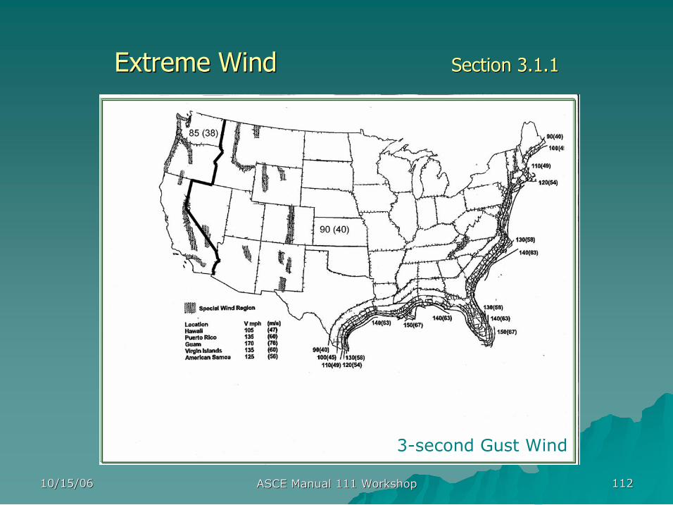
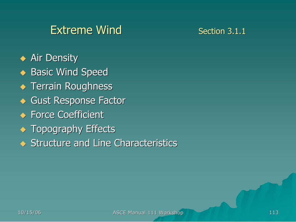
Extreme Wind Extreme Wind Section 3.1.1 Section 3.1.1
3second Gust Wind
10/15/06 10/15/06 ASCE Manual 111 Workshop ASCE Manual 111 Workshop 113 113
u u Air Density Air Density u u Basic Wind Speed Basic Wind Speed u u Terrain Roughness Terrain Roughness u u Gust Response Factor Gust Response Factor u u Force Coefficient Force Coefficient u u Topography Effects Topography Effects u u Structure and Line Characteristics Structure and Line Characteristics
Extreme Wind Extreme Wind Section 3.1.1 Section 3.1.1
10/15/06 10/15/06 ASCE Manual 111 Workshop ASCE Manual 111 Workshop 114 114
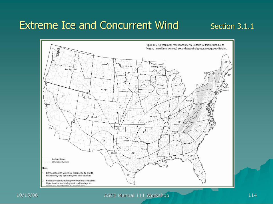
Extreme Ice and Concurrent Wind Extreme Ice and Concurrent Wind Section 3.1.1 Section 3.1.1
10/15/06 10/15/06 ASCE Manual 111 Workshop ASCE Manual 111 Workshop 115 115
u u Vertical Weight Vertical Weight u u Ice Buildup Ice Buildup
– – Projected Area Projected Area – – Force coefficient Force coefficient
u u Tension Tension – – Higher Tension Higher Tension – – Unbalanced Tension Unbalanced Tension
Extreme Ice and Concurrent Wind Extreme Ice and Concurrent Wind Section 3.1.1 Section 3.1.1
♦ ♦ Freezing Rain Freezing Rain
♦ ♦ In In Cloud Icing Cloud Icing
♦ ♦ Wet Snow Wet Snow
♦ ♦ Hoarfrost Hoarfrost
10/15/06 10/15/06 ASCE Manual 111 Workshop ASCE Manual 111 Workshop 116 116
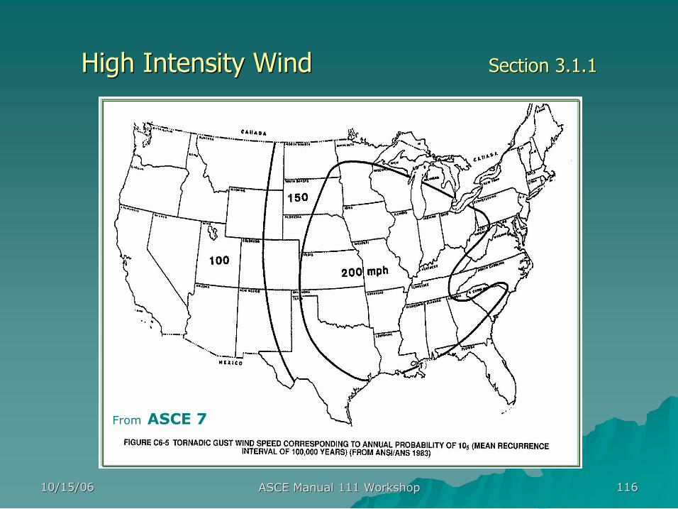
High Intensity Wind High Intensity Wind Section 3.1.1 Section 3.1.1
From ASCE 7
10/15/06 10/15/06 ASCE Manual 111 Workshop ASCE Manual 111 Workshop 117 117
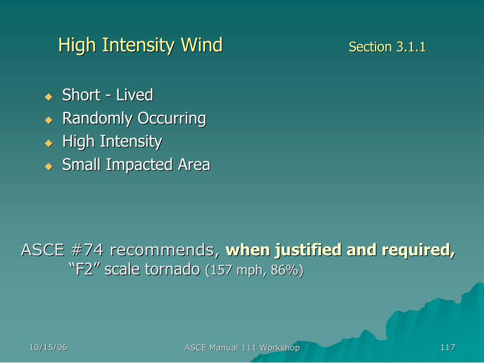
u u Short Short Lived Lived u u Randomly Occurring Randomly Occurring u u High Intensity High Intensity u u Small Impacted Area Small Impacted Area
ASCE #74 recommends, ASCE #74 recommends, when justified and required, when justified and required, “ “F2 F2” ” scale tornado scale tornado (157 mph, 86%) (157 mph, 86%)
High Intensity Wind High Intensity Wind Section 3.1.1 Section 3.1.1
10/15/06 10/15/06 ASCE Manual 111 Workshop ASCE Manual 111 Workshop 118 118
Loads Loads & & Load Effects Load Effects Section 3 Section 3
u u Load Types Load Types (ASCE Manual #74) (ASCE Manual #74)
– – Weather Related Loads Weather Related Loads (Reliability) (Reliability)
u u Extreme Wind, Combined Ice and Wind, High Intensity Wind Extreme Wind, Combined Ice and Wind, High Intensity Wind u u Spatial Influences Spatial Influences u u Alternative Sources Alternative Sources
– – Construction and Maintenance Construction and Maintenance (Safety) (Safety)
– – Failure Containment Failure Containment (Security) (Security)
u u Load Factors Load Factors – – Line System Characteristics Line System Characteristics – – Return Period Adjustments Return Period Adjustments
10/15/06 10/15/06 ASCE Manual 111 Workshop ASCE Manual 111 Workshop 119 119
Line System Characteristics Line System Characteristics Section 3 Section 3
u u Transmission System Transmission System – – Covers larger service territory and could have Covers larger service territory and could have substantial effects when system is not available substantial effects when system is not available
– – Structure supports longer span and higher physical Structure supports longer span and higher physical profile and is more difficult to rebuild or repair when profile and is more difficult to rebuild or repair when damaged damaged
– – The stability of electrical grid could be disturbed by a The stability of electrical grid could be disturbed by a single unplanned failure event single unplanned failure event
10/15/06 10/15/06 ASCE Manual 111 Workshop ASCE Manual 111 Workshop 120 120
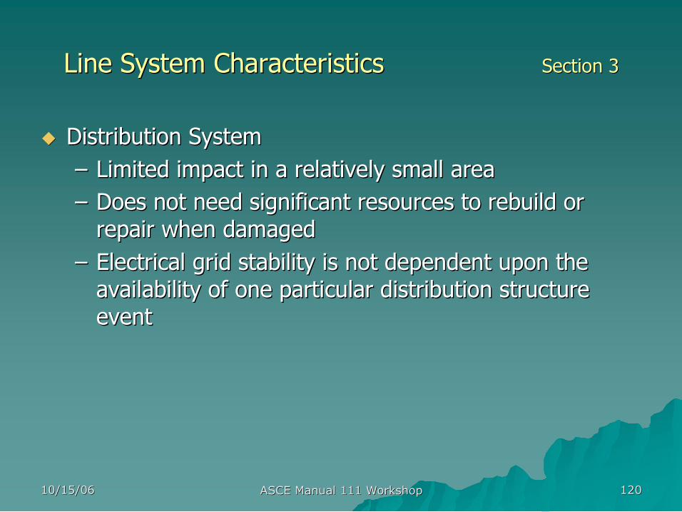
Line System Characteristics Line System Characteristics Section 3 Section 3
u u Distribution System Distribution System – – Limited impact in a relatively small area Limited impact in a relatively small area – – Does not need significant resources to rebuild or Does not need significant resources to rebuild or repair when damaged repair when damaged
– – Electrical grid stability is not dependent upon the Electrical grid stability is not dependent upon the availability of one particular distribution structure availability of one particular distribution structure event event
10/15/06 10/15/06 ASCE Manual 111 Workshop ASCE Manual 111 Workshop 121 121
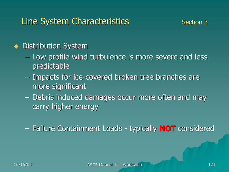
Line System Characteristics Line System Characteristics Section 3 Section 3
u u Distribution System Distribution System – – Low profile wind turbulence is more severe and less Low profile wind turbulence is more severe and less predictable predictable
– – Impacts for ice Impacts for ice covered broken tree branches are covered broken tree branches are more significant more significant
– – Debris induced damages occur more often and may Debris induced damages occur more often and may carry higher energy carry higher energy
– – Failure Containment Loads Failure Containment Loads typically typically NOT NOT considered considered
10/15/06 10/15/06 ASCE Manual 111 Workshop ASCE Manual 111 Workshop 122 122
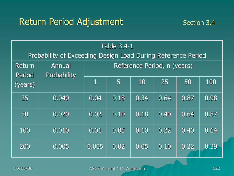
Return Period Adjustment Return Period Adjustment Section 3.4 Section 3.4
Table 3.4 Table 3.4 1 1 Probability of Exceeding Design Load During Reference Period Probability of Exceeding Design Load During Reference Period
0.39 0.39 0.22 0.22 0.10 0.10 0.05 0.05 0.02 0.02 0.005 0.005 0.005 0.005 200 200
0.64 0.64 0.40 0.40 0.22 0.22 0.10 0.10 0.05 0.05 0.01 0.01 0.010 0.010 100 100
0.87 0.87 0.64 0.64 0.40 0.40 0.18 0.18 0.10 0.10 0.02 0.02 0.020 0.020 50 50
0.98 0.98 0.87 0.87 0.64 0.64 0.34 0.34 0.18 0.18 0.04 0.04 0.040 0.040 25 25
100 100 50 50 25 25 10 10 5 5 1 1
Reference Period, n (years) Reference Period, n (years) Annual Annual Probability Probability
Return Return Period Period (years) (years)
10/15/06 10/15/06 ASCE Manual 111 Workshop ASCE Manual 111 Workshop 123 123
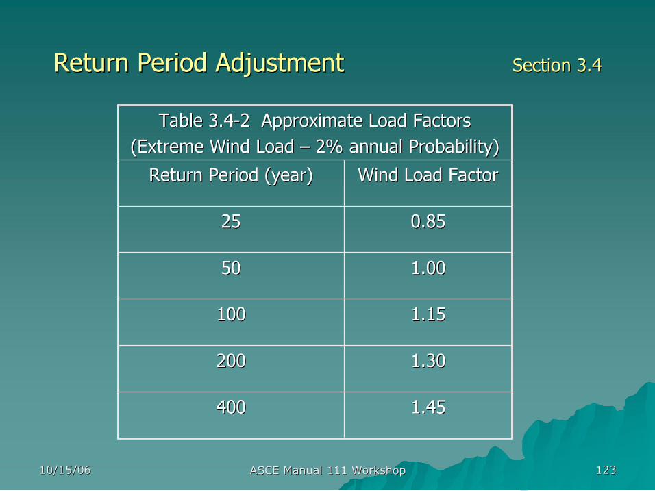
Return Period Adjustment Return Period Adjustment Section 3.4 Section 3.4
1.45 1.45 400 400
1.30 1.30 200 200
1.15 1.15 100 100
1.00 1.00 50 50
0.85 0.85 25 25
Wind Load Factor Wind Load Factor Return Period (year) Return Period (year)
Table 3.4 Table 3.4 2 Approximate Load Factors 2 Approximate Load Factors (Extreme Wind Load (Extreme Wind Load – – 2% annual Probability) 2% annual Probability)
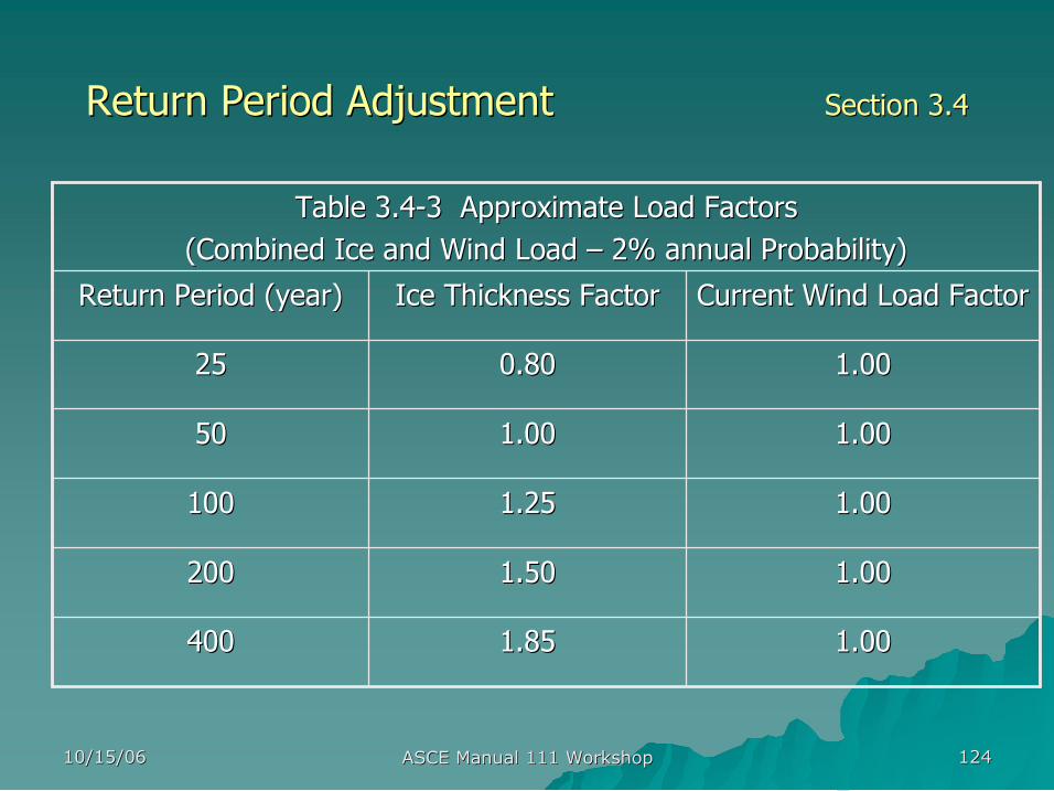
10/15/06 10/15/06 ASCE Manual 111 Workshop ASCE Manual 111 Workshop 124 124
Return Period Adjustment Return Period Adjustment Section 3.4 Section 3.4
1.00 1.00 1.85 1.85 400 400
1.00 1.00 1.50 1.50 200 200
1.00 1.00 1.25 1.25 100 100
1.00 1.00 1.00 1.00 50 50
1.00 1.00 0.80 0.80 25 25
Current Wind Load Factor Current Wind Load Factor Ice Thickness Factor Ice Thickness Factor Return Period (year) Return Period (year)
Table 3.4 Table 3.4 3 Approximate Load Factors 3 Approximate Load Factors (Combined Ice and Wind Load (Combined Ice and Wind Load – – 2% annual Probability) 2% annual Probability)

Single Pole LRFD Single Pole LRFD Nominal Resistance Nominal Resistance
presented by presented by
Ron Wolfe Ron Wolfe Research Engineer Research Engineer
US Forest Products Laboratory US Forest Products Laboratory
Next: Next:
10/15/06 10/15/06 ASCE Manual 111 Workshop ASCE Manual 111 Workshop 126 126
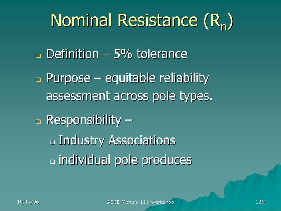
Nominal Resistance ( Nominal Resistance (R R n n ) )
q q Definition Definition – – 5% tolerance 5% tolerance
q q Purpose Purpose – – equitable reliability equitable reliability assessment across pole types. assessment across pole types.
q q Responsibility Responsibility – –
q q Industry Associations Industry Associations
q q individual pole produces individual pole produces

10/15/06 10/15/06 ASCE Manual 111 Workshop ASCE Manual 111 Workshop 127 127
Objective Objective
q q Discuss three options for the evaluation of Discuss three options for the evaluation of nominal resistance for LRFD (Section 4) nominal resistance for LRFD (Section 4)
q q Relate options to material being used Relate options to material being used
10/15/06 10/15/06 ASCE Manual 111 Workshop ASCE Manual 111 Workshop 128 128
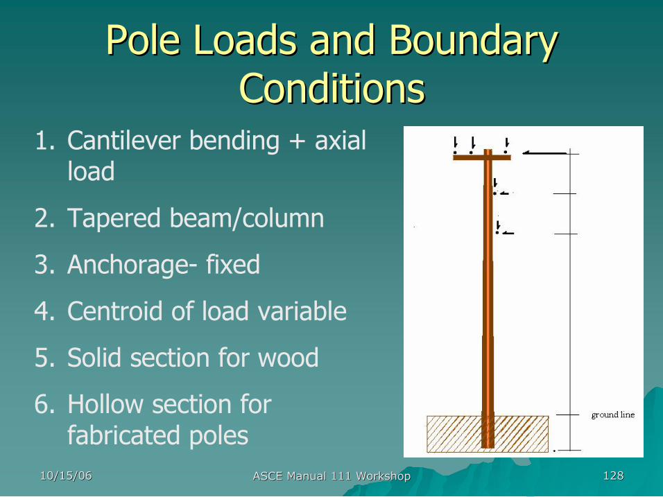
Pole Loads and Boundary Pole Loads and Boundary Conditions Conditions
1. Cantilever bending + axial load
2. Tapered beam/column
3. Anchorage fixed
4. Centroid of load variable
5. Solid section for wood
6. Hollow section for fabricated poles
10/15/06 10/15/06 ASCE Manual 111 Workshop ASCE Manual 111 Workshop 129 129
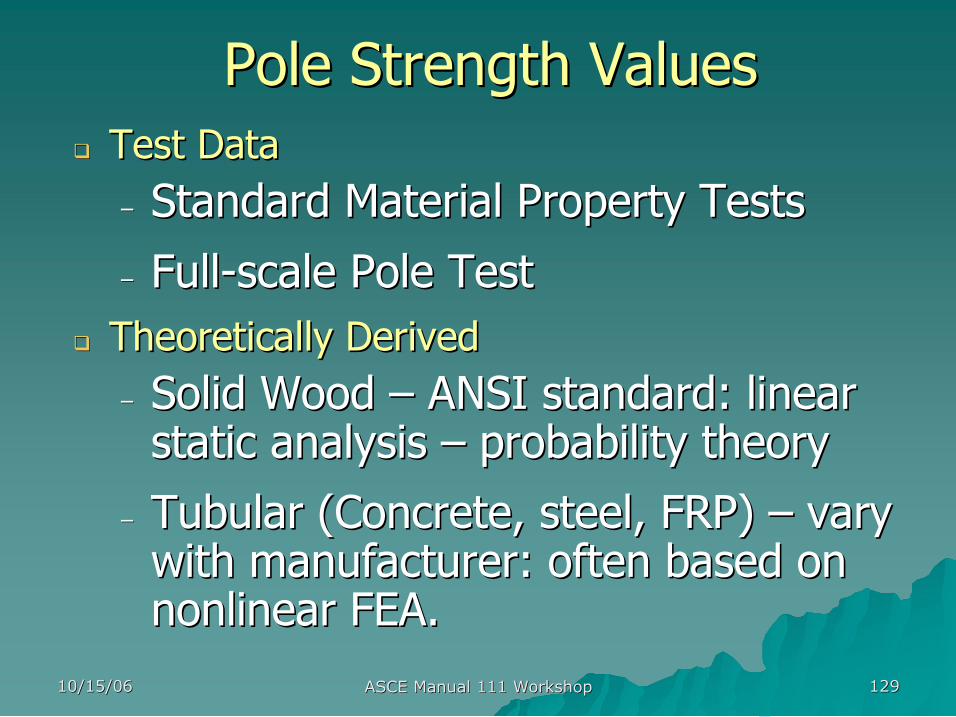
Pole Strength Values Pole Strength Values q q Test Data Test Data
– – Standard Material Property Tests Standard Material Property Tests
– – Full Full scale Pole Test scale Pole Test q q Theoretically Derived Theoretically Derived
– – Solid Wood Solid Wood – – ANSI standard: linear ANSI standard: linear static analysis static analysis – – probability theory probability theory
– – Tubular (Concrete, steel, FRP) Tubular (Concrete, steel, FRP) – – vary vary with manufacturer: often based on with manufacturer: often based on nonlinear FEA. nonlinear FEA.
10/15/06 10/15/06 ASCE Manual 111 Workshop ASCE Manual 111 Workshop 130 130
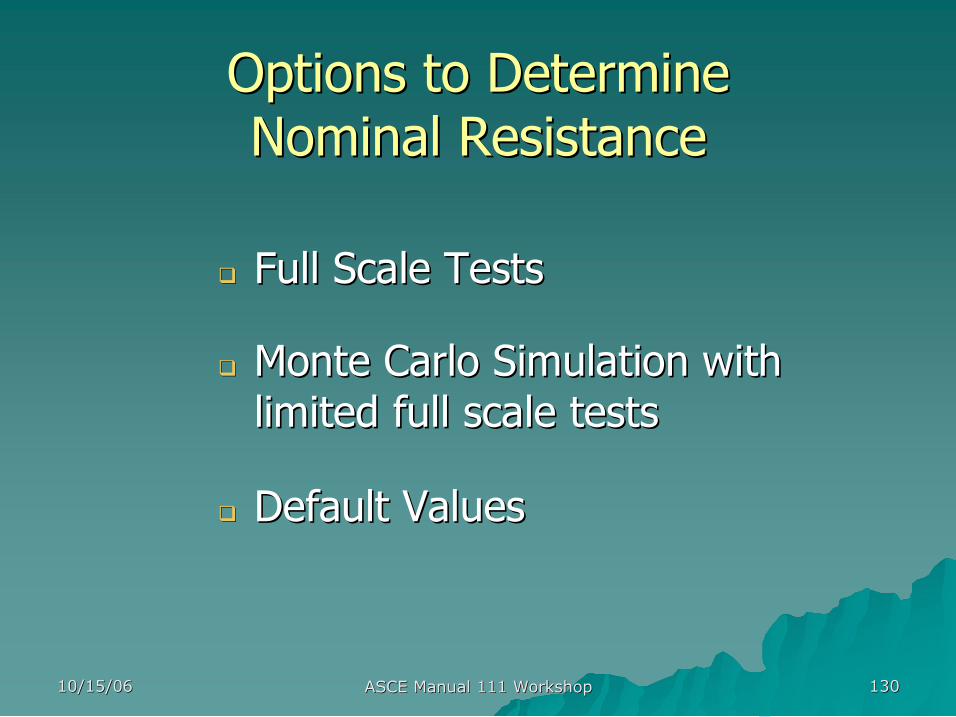
Options to Determine Options to Determine Nominal Resistance Nominal Resistance
q q Full Scale Tests Full Scale Tests
q q Monte Carlo Simulation with Monte Carlo Simulation with limited full scale tests limited full scale tests
q q Default Values Default Values
10/15/06 10/15/06 ASCE Manual 111 Workshop ASCE Manual 111 Workshop 131 131
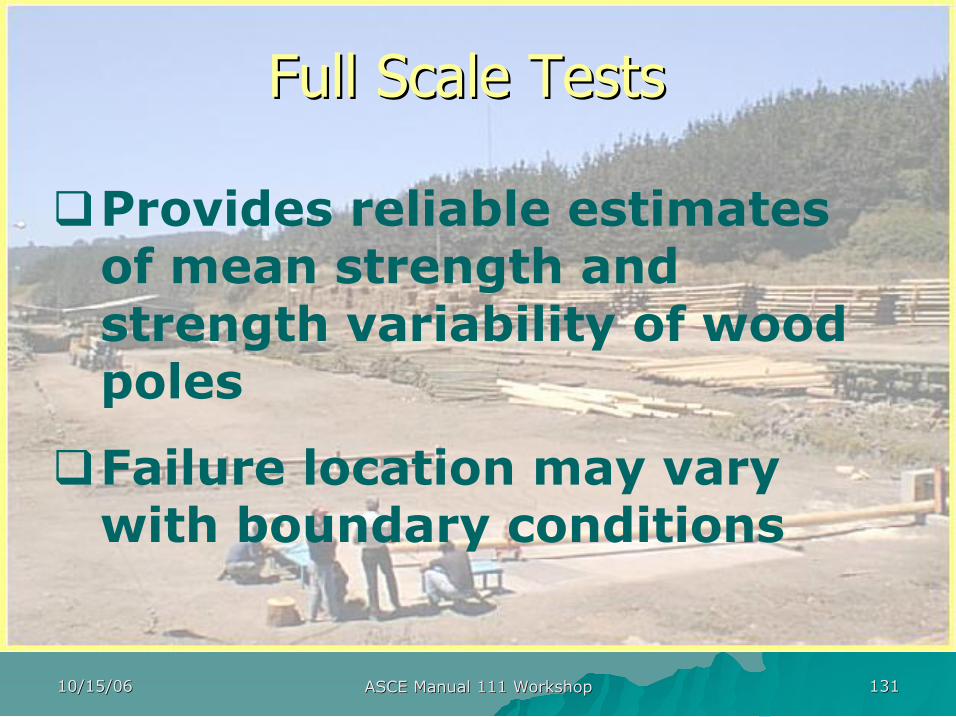
Full Scale Tests Full Scale Tests
qProvides reliable estimates of mean strength and strength variability of wood poles
qFailure location may vary with boundary conditions
10/15/06 10/15/06 ASCE Manual 111 Workshop ASCE Manual 111 Workshop 132 132
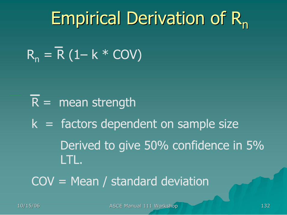
Empirical Derivation of Empirical Derivation of R R n n
R n = R (1– k * COV)
R = mean strength
k = factors dependent on sample size
Derived to give 50% confidence in 5% LTL.
COV = Mean / standard deviation
10/15/06 10/15/06 ASCE Manual 111 Workshop ASCE Manual 111 Workshop 133 133
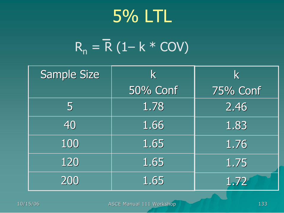
5% LTL
1.65 1.65 200 200
1.65 1.65 120 120
1.65 1.65 100 100
1.66 1.66 40 40
1.78 1.78 5 5
k k 50% Conf 50% Conf
Sample Size Sample Size
1.72 1.72
1.75 1.75
1.76 1.76
1.83 1.83
2.46 2.46
k k 75% Conf 75% Conf
R n = R (1– k * COV)
10/15/06 10/15/06 ASCE Manual 111 Workshop ASCE Manual 111 Workshop 134 134
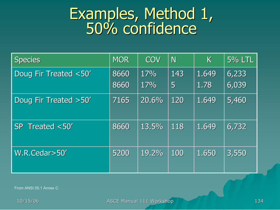
Examples, Method 1, Examples, Method 1, 50% confidence 50% confidence
5,460 5,460 1.649 1.649 120 120 20.6% 20.6% 7165 7165 Doug Fir Treated >50 Doug Fir Treated >50’ ’
3,550 3,550 1.650 1.650 100 100 19.2% 19.2% 5200 5200 W.R.Cedar>50 W.R.Cedar>50’ ’
6,732 6,732 1.649 1.649 118 118 13.5% 13.5% 8660 8660 SP Treated <50 SP Treated <50’ ’
6,233 6,233 6,039 6,039
1.649 1.649 1.78 1.78
143 143 5 5
17% 17% 17% 17%
8660 8660 8660 8660
Doug Fir Treated <50 Doug Fir Treated <50’ ’
5% LTL 5% LTL K K N N COV COV MOR MOR Species Species
From ANSI 05.1 Annex C
10/15/06 10/15/06 ASCE Manual 111 Workshop ASCE Manual 111 Workshop 135 135
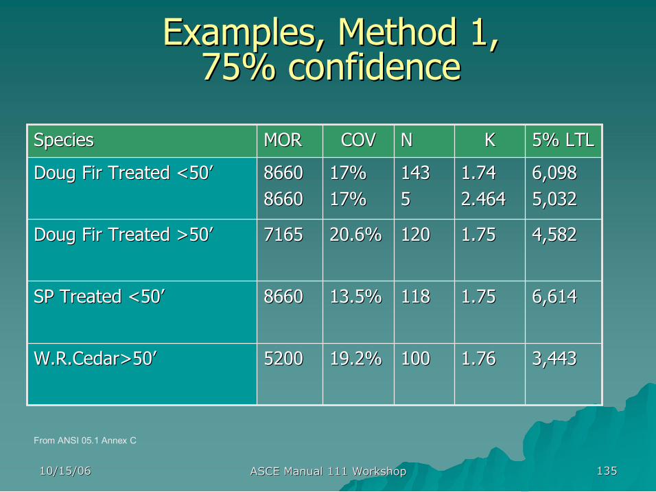
Examples, Method 1, Examples, Method 1, 75% confidence 75% confidence
4,582 4,582 1.75 1.75 120 120 20.6% 20.6% 7165 7165 Doug Fir Treated >50 Doug Fir Treated >50’ ’
3,443 3,443 1.76 1.76 100 100 19.2% 19.2% 5200 5200 W.R.Cedar>50 W.R.Cedar>50’ ’
6,614 6,614 1.75 1.75 118 118 13.5% 13.5% 8660 8660 SP Treated <50 SP Treated <50’ ’
6,098 6,098 5,032 5,032
1.74 1.74 2.464 2.464
143 143 5 5
17% 17% 17% 17%
8660 8660 8660 8660
Doug Fir Treated <50 Doug Fir Treated <50’ ’
5% LTL 5% LTL K K N N COV COV MOR MOR Species Species
From ANSI 05.1 Annex C
10/15/06 10/15/06 ASCE Manual 111 Workshop ASCE Manual 111 Workshop 136 136
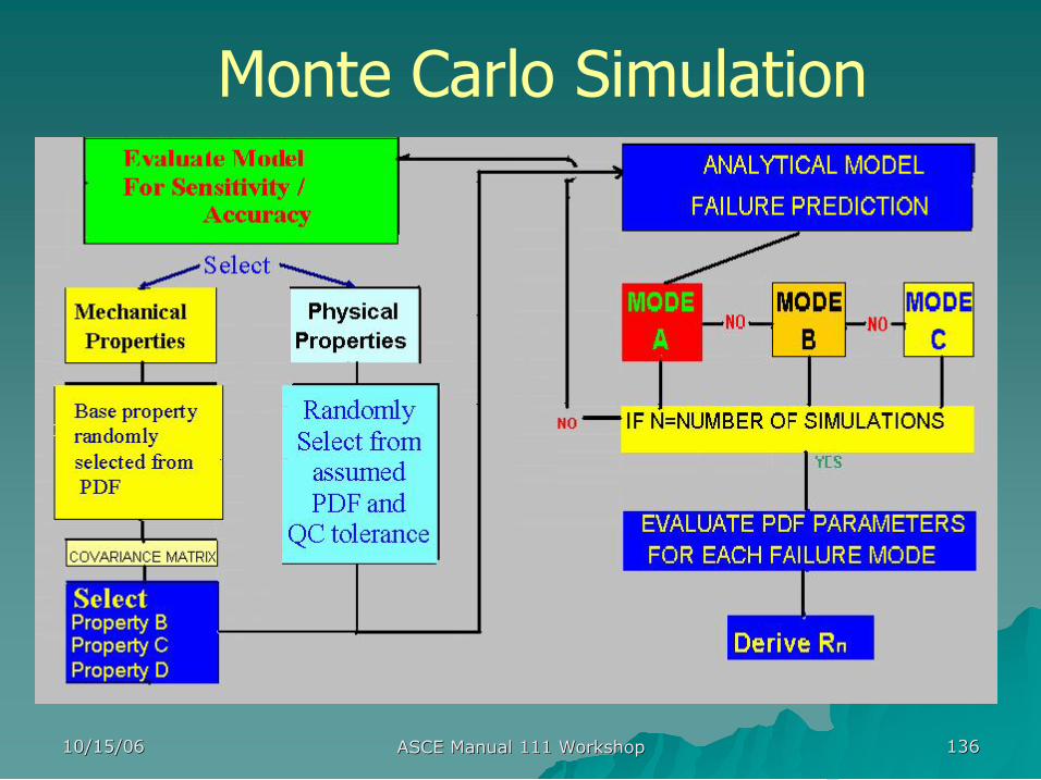
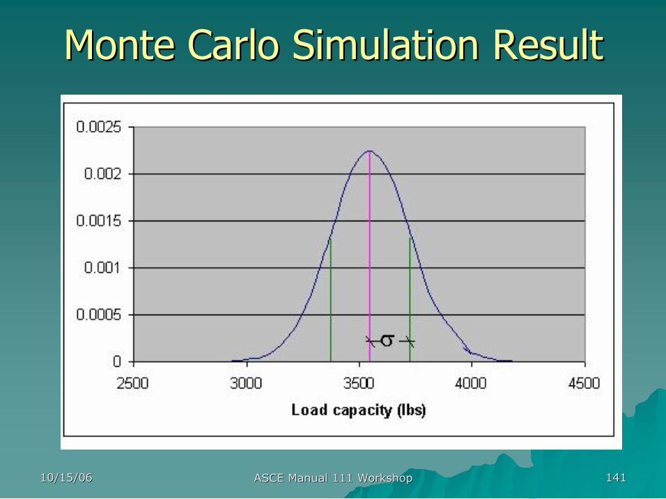
Monte Carlo Simulation
10/15/06 10/15/06 ASCE Manual 111 Workshop ASCE Manual 111 Workshop 137 137
Test Model Accuracy
q Assess model sensitivity to each variable
qEvaluate covariance matrix for important variables
qVerify model by testing extremes of influencing variables.
q Evaluate Model Adjustment Factor
10/15/06 10/15/06 ASCE Manual 111 Workshop ASCE Manual 111 Workshop 138 138
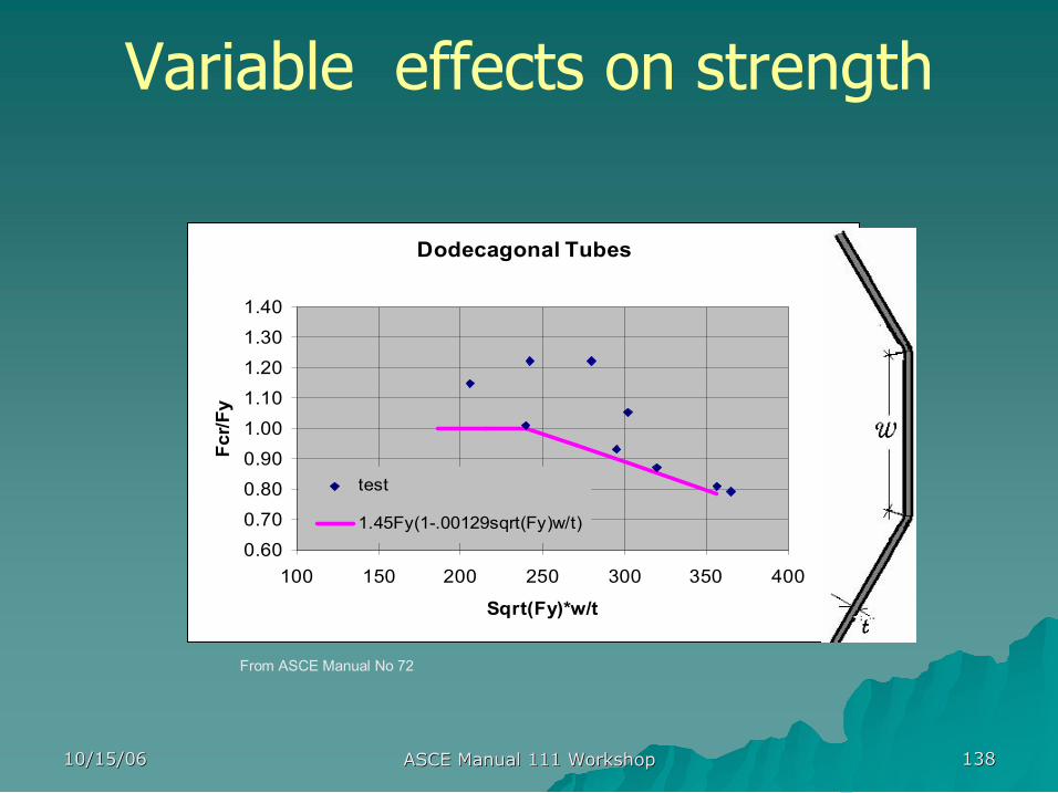
Variable effects on strength
Dodecagonal Tubes
0.60 0.70 0.80 0.90 1.00 1.10 1.20 1.30 1.40
100 150 200 250 300 350 400
Sqrt(Fy)*w/t
Fcr/F
y
test
1.45Fy(1.00129sqrt(Fy)w/t)
From ASCE Manual No 72
10/15/06 10/15/06 ASCE Manual 111 Workshop ASCE Manual 111 Workshop 139 139
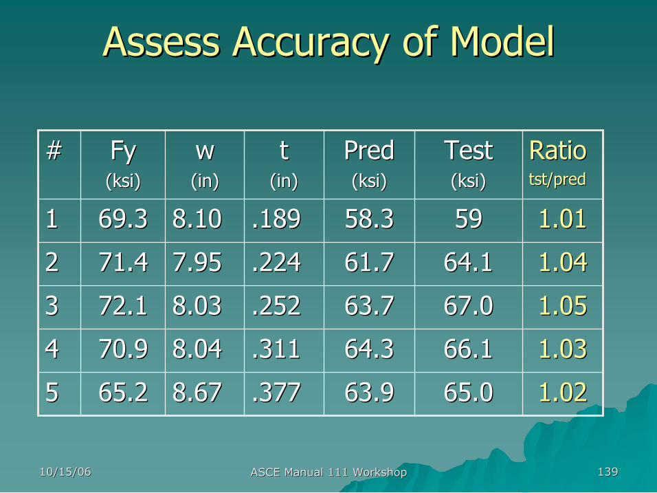
Assess Accuracy of Model Assess Accuracy of Model
1.02 1.02 65.0 65.0 63.9 63.9 .377 .377 8.67 8.67 65.2 65.2 5 5
1.03 1.03 66.1 66.1 64.3 64.3 .311 .311 8.04 8.04 70.9 70.9 4 4
1.05 1.05 67.0 67.0 63.7 63.7 .252 .252 8.03 8.03 72.1 72.1 3 3
1.04 1.04 64.1 64.1 61.7 61.7 .224 .224 7.95 7.95 71.4 71.4 2 2
1.01 1.01 59 59 58.3 58.3 .189 .189 8.10 8.10 69.3 69.3 1 1
Ratio Ratio tst/pred tst/pred
Test Test ( (ksi ksi) )
Pred Pred ( (ksi ksi) )
t t(in) (in)
w w (in) (in)
Fy Fy ( (ksi ksi) )
# #

10/15/06 10/15/06 ASCE Manual 111 Workshop ASCE Manual 111 Workshop 140 140
Evaluate Model Adjustment Evaluate Model Adjustment Factor Factor
1.005 1.01 1.015 1.02 1.025 1.03 1.035 1.04 1.045 1.05 1.055 1.06
100 150 200 250 300 350 400
Sqrt(Fy)*w/t
Ratio pred/test
10/15/06 10/15/06 ASCE Manual 111 Workshop ASCE Manual 111 Workshop 141 141
Monte Carlo Simulation Result Monte Carlo Simulation Result
10/15/06 10/15/06 ASCE Manual 111 Workshop ASCE Manual 111 Workshop 142 142
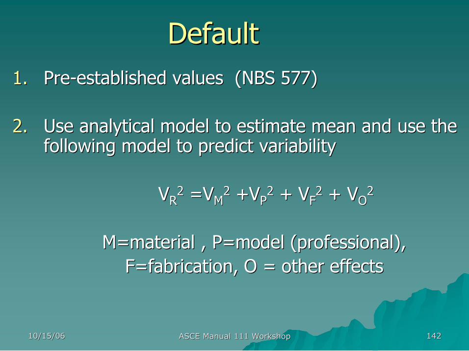
Default Default 1. 1. Pre Pre established values (NBS 577) established values (NBS 577)
2. 2. Use analytical model to estimate mean and use the Use analytical model to estimate mean and use the following model to predict variability following model to predict variability
V V R R 2 2 =V =V M M 2 2 +V +V P P 2 2 + V + V F F 2 2 + V + V O O 2 2
M=material , P=model (professional), M=material , P=model (professional), F=fabrication, O = other effects F=fabrication, O = other effects

10/15/06 10/15/06 ASCE Manual 111 Workshop ASCE Manual 111 Workshop 143 143
Conclusions Conclusions u u Empirical derivations require repetitive testing and Empirical derivations require repetitive testing and analysis following standardized procedures. analysis following standardized procedures.
u u Monte Carlo simulation is most appropriate for Monte Carlo simulation is most appropriate for manufactured poles. manufactured poles.
u u Default values should be conservatively derived to Default values should be conservatively derived to encourage more rigorous model development and encourage more rigorous model development and test verification. test verification.
u u Time and experience provide the ultimate test of Time and experience provide the ultimate test of structural reliability. structural reliability.
10/15/06 10/15/06 ASCE Manual 111 Workshop ASCE Manual 111 Workshop 144 144
Two Points to Remember Two Points to Remember
u u Nominal Strength at 5% LEL Nominal Strength at 5% LEL u u Same loads and load factors for all Same loads and load factors for all materials materials
10/15/06 10/15/06 ASCE Manual 111 Workshop ASCE Manual 111 Workshop 145 145
Quiz: Quiz: What strength should we use? What strength should we use? What load should we use? What load should we use?
Load Q
m Q Q 50
Strength R
m R R 5

10/15/06 10/15/06 ASCE Manual 111 Workshop ASCE Manual 111 Workshop 146 146
Quiz: How do we achieve relatively Quiz: How do we achieve relatively consistent reliability across consistent reliability across materials and locations? materials and locations? Load Q
m Q Q 50
Strength R
m R R 5

Appendix B Appendix B
Design Examples Design Examples
Next: Next:
presented by presented by
Ron Randle Ron Randle – – EDM International EDM International
Ft. Collins, Colorado Ft. Collins, Colorado
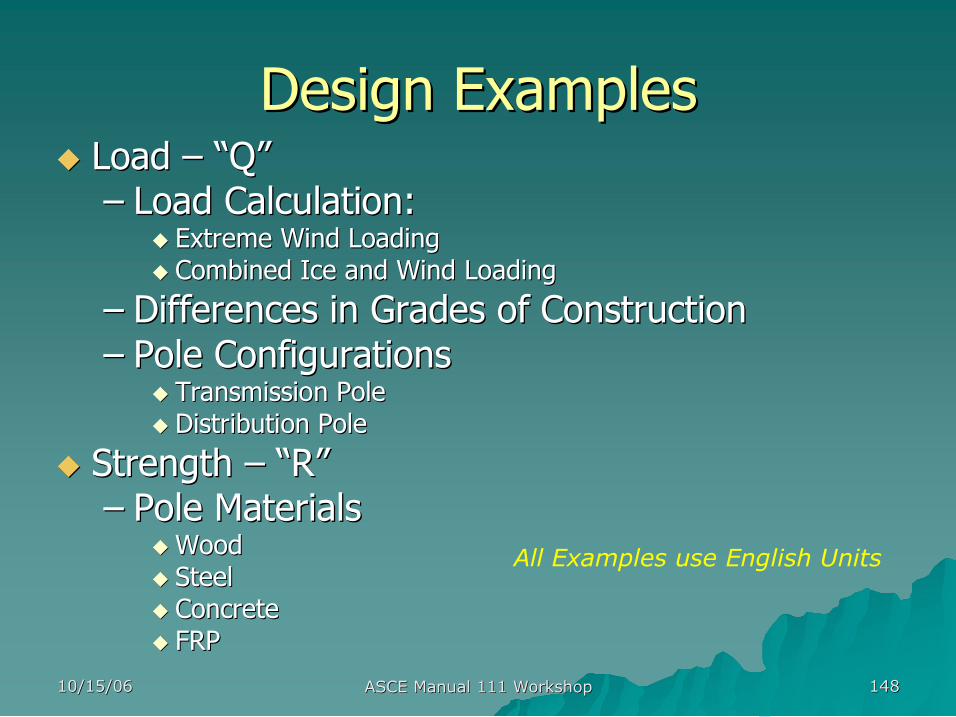
10/15/06 10/15/06 ASCE Manual 111 Workshop ASCE Manual 111 Workshop 148 148
Design Examples Design Examples u u Load Load – – “ “Q Q” ” – – Load Calculation: Load Calculation:
u u Extreme Wind Loading Extreme Wind Loading u u Combined Ice and Wind Loading Combined Ice and Wind Loading
– – Differences in Grades of Construction Differences in Grades of Construction – – Pole Configurations Pole Configurations
u u Transmission Pole Transmission Pole u u Distribution Pole Distribution Pole
u u Strength Strength – – “ “R R” ” – – Pole Materials Pole Materials
u u Wood Wood u u Steel Steel u u Concrete Concrete u u FRP FRP
All Examples use English Units
10/15/06 10/15/06 ASCE Manual 111 Workshop ASCE Manual 111 Workshop 149 149
LOAD
10/15/06 10/15/06 ASCE Manual 111 Workshop ASCE Manual 111 Workshop 150 150
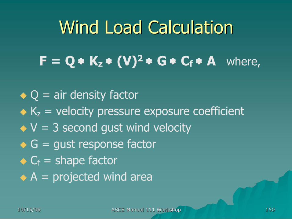
Wind Load Calculation Wind Load Calculation
F = Q ∗ Kz ∗ (V) 2 ∗ G ∗ Cf ∗ A where,
u Q = air density factor u Kz = velocity pressure exposure coefficient u V = 3 second gust wind velocity u G = gust response factor u Cf = shape factor u A = projected wind area
10/15/06 10/15/06 ASCE Manual 111 Workshop ASCE Manual 111 Workshop 151 151
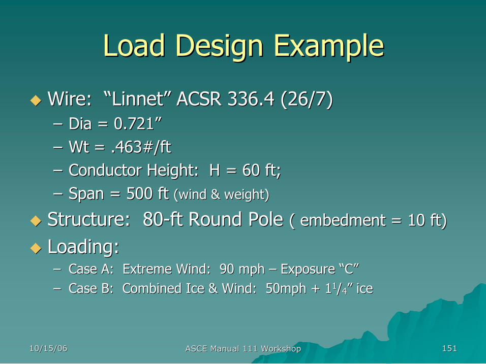
Load Design Example Load Design Example
u u Wire: Wire: “ “Linnet Linnet” ” ACSR 336.4 (26/7) ACSR 336.4 (26/7) – – Dia = 0.721 Dia = 0.721” ” – – Wt = .463#/ft Wt = .463#/ft – – Conductor Height: H = 60 ft; Conductor Height: H = 60 ft; – – Span = 500 ft Span = 500 ft (wind & weight) (wind & weight)
u u Structure: 80 Structure: 80 ft Round Pole ft Round Pole ( embedment = 10 ft) ( embedment = 10 ft)
u u Loading: Loading: – – Case A: Extreme Wind: 90 mph Case A: Extreme Wind: 90 mph – – Exposure Exposure “ “C C” ” – – Case B: Combined Ice & Wind: 50mph + 1 Case B: Combined Ice & Wind: 50mph + 1 1 1 / /4 4” ” ice ice
10/15/06 10/15/06 ASCE Manual 111 Workshop ASCE Manual 111 Workshop 152 152
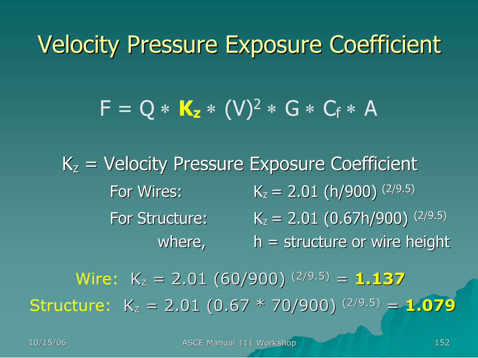
Velocity Pressure Exposure Coefficient Velocity Pressure Exposure Coefficient
F = Q ∗ Kz ∗ (V) 2 ∗ G ∗ Cf ∗ A
K Kz z = Velocity Pressure Exposure Coefficient = Velocity Pressure Exposure Coefficient For Wires: For Wires: K Kz z = 2.01 (h/900) = 2.01 (h/900) (2/9.5) (2/9.5)
For Structure: For Structure: K Kz z = 2.01 (0.67h/900) = 2.01 (0.67h/900) (2/9.5) (2/9.5)
where, where, h = structure or wire height h = structure or wire height
Wire: K Kz z = 2.01 (60/900) = 2.01 (60/900) (2/9.5) (2/9.5) = = 1.137 1.137
Structure: K Kz z = 2.01 (0.67 * 70/900) = 2.01 (0.67 * 70/900) (2/9.5) (2/9.5) = = 1.079 1.079
10/15/06 10/15/06 ASCE Manual 111 Workshop ASCE Manual 111 Workshop 153 153
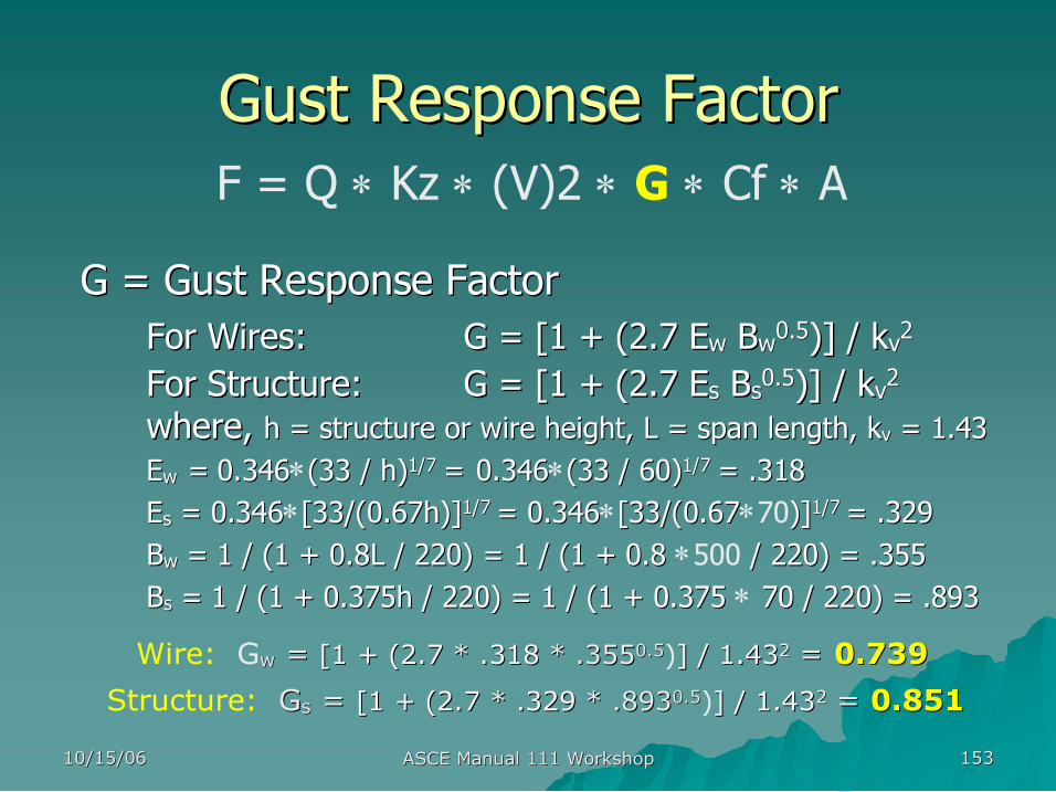
Gust Response Factor Gust Response Factor F = Q ∗ Kz ∗ (V)2 ∗ G ∗ Cf ∗ A
G = Gust Response Factor G = Gust Response Factor For Wires: For Wires: G = [1 + (2.7 G = [1 + (2.7 E Ew w B Bw w 0.5 0.5 )] / k )] / kv v 2 2
For Structure: For Structure: G = [1 + (2.7 E G = [1 + (2.7 Es s B Bs s 0.5 0.5 )] / k )] / kv v 2 2 where, where, h = structure or wire height, L = span length, h = structure or wire height, L = span length, k kv v = 1.43 = 1.43 E Ew w = = 0.346 0.346∗(33 / h) (33 / h) 1/7 1/7 = = 0.346 0.346∗(33 / 60) (33 / 60) 1/7 1/7 = .318 = .318 E Es s = 0.346 = 0.346∗[33/(0.67h)] [33/(0.67h)] 1/7 1/7 = 0.346 = 0.346∗[33/(0.67 [33/(0.67∗70)] )] 1/7 1/7 = .329 = .329 B Bw w = = 1 / (1 + 0.8L / 220) = 1 / (1 + 0.8 1 / (1 + 0.8L / 220) = 1 / (1 + 0.8 ∗500 / 220) = .355 / 220) = .355 B Bs s = = 1 / (1 + 0.375h / 220) = 1 / (1 + 0.375 1 / (1 + 0.375h / 220) = 1 / (1 + 0.375 ∗ 70 / 220) = .893 70 / 220) = .893
Wire: Gw w = = [1 + (2.7 [1 + (2.7 * * .318 .318 * .355 * .355 0.5 0.5 )] / 1.43 ] / 1.43 2 2 = = 0.739 0.739
Structure: G Gs s = = [1 + (2.7 [1 + (2.7 * * .329 .329 * .893 * .893 0.5 0.5 )] / 1.43 ] / 1.43 2 2 = = 0.851 0.851
10/15/06 10/15/06 ASCE Manual 111 Workshop ASCE Manual 111 Workshop 154 154
Shape Factor Shape Factor
F = Q ∗ Kz ∗ (V) 2 ∗ G ∗ Cf ∗ A Cf = Shape Factor: • For Wires – Cf = 1.0 • For Members – Cf = 0.9 for circular and 16sided shapes 1.0 for 12sided shapes 1.4 for 8 and 6sided shapes 2.0 for square and rectangular shapes
Wires: Cf = 1.0 and Round Pole: Cf = 0.9
10/15/06 10/15/06 ASCE Manual 111 Workshop ASCE Manual 111 Workshop 155 155
Summary of Wind Load Factors Summary of Wind Load Factors u u Extreme Wind: 90 mph Extreme Wind: 90 mph – – Exposure Exposure “ “C C” ”
Wire Structure Q = 0.00256 same Kz = 1.137 1.079 V = 90 mph same G = 0.739 0.851 Cf = 1.0 0.9 (ASCE Manual 741991 – Table 2.63)
u Combined Ice & Wind V = 50 mph same

10/15/06 10/15/06 ASCE Manual 111 Workshop ASCE Manual 111 Workshop 156 156
Load Calculations Load Calculations
F = Q ∗ Kz ∗ (V) 2 ∗ G ∗ Cf ∗ A uExtreme Wind:
– Tw = .00256 ∗ 1.137 ∗ (90) 2 ∗ 0.739 ∗ 1.0 ∗ A = 17.4 ∗ A – Ts = .00256 ∗ 1.079 ∗ (90) 2 ∗ 0.851 ∗ 0.9 ∗ A = 17.1 ∗ A
uCombined Ice and Wind: – Tw = .00256 ∗ 1.137 ∗ (50) 2 ∗ 0.739 ∗ 1.0 ∗ A = 5.37 ∗ A – Ts = .00256 ∗ 1.079 ∗ (50) 2 ∗ 0.851 ∗ 0.9 ∗ A = 5.29 ∗ A

10/15/06 10/15/06 ASCE Manual 111 Workshop ASCE Manual 111 Workshop 157 157
Load Factors ( Load Factors (γ γ) )
u u NESC Grade NESC Grade “ “B B” ” Construction; Construction; β β = 2.0 = 2.0 u u NESC Grade NESC Grade “ “C C” ” Construction; Construction; β β = 1.5 = 1.5
Reference: RBD Manual 111 – Table 2.3
Load Factors (γ) Load Case: Extreme Wind Ice + Wind
Reliability Index: β = 2.0 β = 1.5 β = 2.0 β = 1.5 Wind Force 1.0 0.5 a 1.0 1.0 Ice Thickness na na 1.0 b 0.5 b
Dead Load (Wires + Str. Weight) 1.1 1.1 1.1 1.1 a If any portion of the structure or its supported facilities exceed 60 ft above ground , a load factor of 1.0 should be used. b The load factor for the ice thickness is to be applied to the thickness of the ice prior to calculating the associated load.
10/15/06 10/15/06 ASCE Manual 111 Workshop ASCE Manual 111 Workshop 158 158
Example: Extreme Wind Example: Extreme Wind
u Wind Velocity = 90 mph u Wire: ACSR 336.4 (26/7)
Dia = 0.721 Dia = 0.721” ”; Wt = .463#/ft; Span = 500 ft ; Wt = .463#/ft; Span = 500 ft – Tw = γw ∗ 17.4 ∗ A = 1.0 ∗ 17.4 ∗ (0.721/12) ∗ 500 = 523 lbs
u Structure: Round Pole (70ft above GL) Dia top = 9.0 in.; Dia gl = 19.5 in.;
– Ts = γw ∗ 17.1 ∗ A = 1.0 ∗ 17.1 ∗ [(9.0 + 19.5)/(2 ∗ 12)] ∗ 70 = 1421 lbs
u Grade of Construction (taller than 60ft above GL) – Grade B: γw = 1.0; γdl = 1.1 – Grade C: γw = 1.0; γdl = 1.1

10/15/06 10/15/06 ASCE Manual 111 Workshop ASCE Manual 111 Workshop 159 159
Shorter Pole Shorter Pole Extreme Wind Extreme Wind
uGrade of Construction (60ft or less above GL) – Grade B: γw = 1.0; γdl = 1.1 – Grade C: γw = 0.5; γdl = 1.1
Load Factors (γ) Load Case: Extreme Wind Ice + Wind
Reliability Index: β = 2.0 β = 1.5 β = 2.0 β = 1.5 Wind Force 1.0 0.5 a 1.0 1.0 Ice Thickness na na 1.0 b 0.5 b
Dead Load (Wires + Str. Weight) 1.1 1.1 1.1 1.1 a If any portion of the structure or its supported facilities exceed 60 ft above ground , a load factor of 1.0 should be used. b The load factor for the ice thickness is to be applied to the thickness of the ice prior to calculating the associated load.
10/15/06 10/15/06 ASCE Manual 111 Workshop ASCE Manual 111 Workshop 160 160
Example: Ice + Wind Example: Ice + Wind u Wire: ACSR 336.4 (26/7)
Dia = 0.721 Dia = 0.721” ”; Wt = .463#/ft; Span = 500 ft ; Wt = .463#/ft; Span = 500 ft – T50 = γwind ∗ 5.37 ∗ A = γwind ∗ 5.37 ∗ [(γice ∗ 2.5 + 0.721)/12] ∗ 500 = – Grade “B” Construction (γwind = 1.0; γice = 1.0): T50 = 721 lbs – Grade “C” Construction (γwind = 1.0; γice = 0.5): T50 = 441 lbs
u Structure: Round Pole Dia top = 9.0 in.; Dia gl = 19.5 in.;
– T50 = γwind ∗ 5.29 ∗ A = 5.29 ∗ [(9.0 + 19.5)/(2 ∗ 12)] ∗ 70 = – Grade “B” Construction (γwind = 1.0): T50 = 440 lbs – Grade “C” Construction (γwind = 1.0): T50 = 440 lbs
u Vertical Loads (except ice) – Grade B: γdl = 1.1 – Grade C: γdl = 1.1

10/15/06 10/15/06 ASCE Manual 111 Workshop ASCE Manual 111 Workshop 161 161
STRENGTH
10/15/06 10/15/06 ASCE Manual 111 Workshop ASCE Manual 111 Workshop 162 162
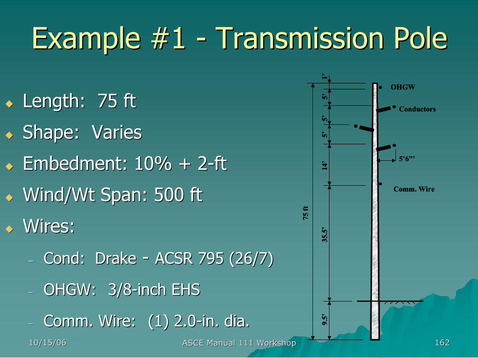
Example #1 Example #1 Transmission Pole Transmission Pole
u u Length: 75 ft Length: 75 ft
u u Shape: Varies Shape: Varies
u u Embedment: 10% + 2 Embedment: 10% + 2 ft ft
u u Wind/Wt Span: 500 ft Wind/Wt Span: 500 ft
u u Wires: Wires:
– – Cond Cond: Drake : Drake ACSR 795 (26/7) ACSR 795 (26/7)
– – OHGW: OHGW: 3/8 3/8 inch EHS inch EHS
– – Comm. Wire: Comm. Wire: (1) 2.0 (1) 2.0 in. dia. in. dia. 75 ft
5’
5’
5’
1’
9.5’
35.5’
14’
Conductors
OHGW
Comm. Wire
5’6”’
75 ft
5’
5’
5’
1’
9.5’
35.5’
14’
Conductors
OHGW
Comm. Wire
5’6”’
10/15/06 10/15/06 ASCE Manual 111 Workshop ASCE Manual 111 Workshop 163 163
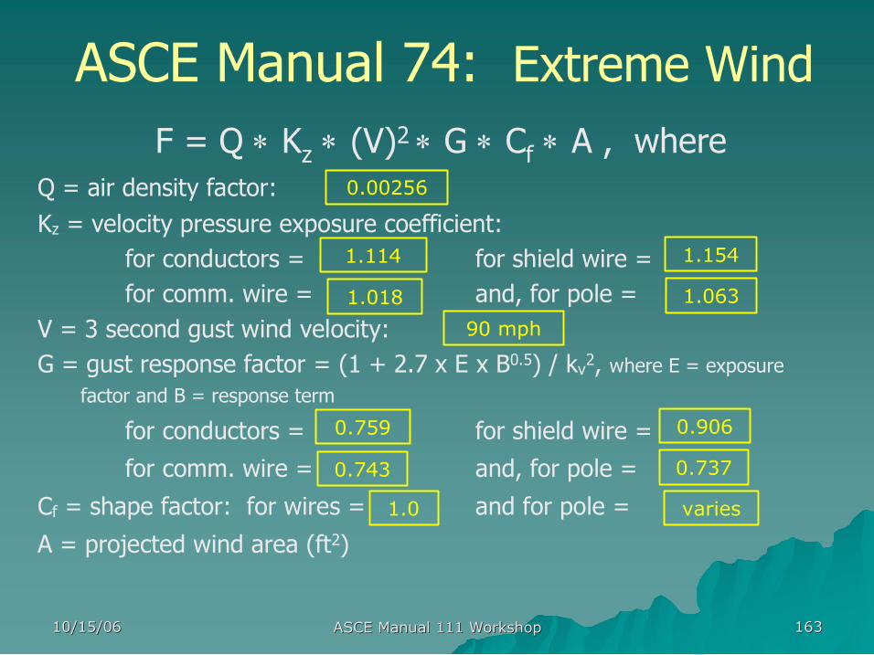
ASCE Manual 74: Extreme Wind F = Q ∗ K z ∗ (V) 2 ∗ G ∗ C f ∗ A , where
Q = air density factor: Kz = velocity pressure exposure coefficient:
for conductors = for shield wire = for comm. wire = and, for pole =
V = 3 second gust wind velocity: G = gust response factor = (1 + 2.7 x E x B 0.5 ) / kv 2 , where E = exposure
factor and B = response term
for conductors = for shield wire =
for comm. wire = and, for pole =
Cf = shape factor: for wires = and for pole =
A = projected wind area (ft 2 )
0.00256
0.906 0.759
0.737 0.743
1.063 1.018
1.154 1.114
varies 1.0
90 mph
10/15/06 10/15/06 ASCE Manual 111 Workshop ASCE Manual 111 Workshop 164 164
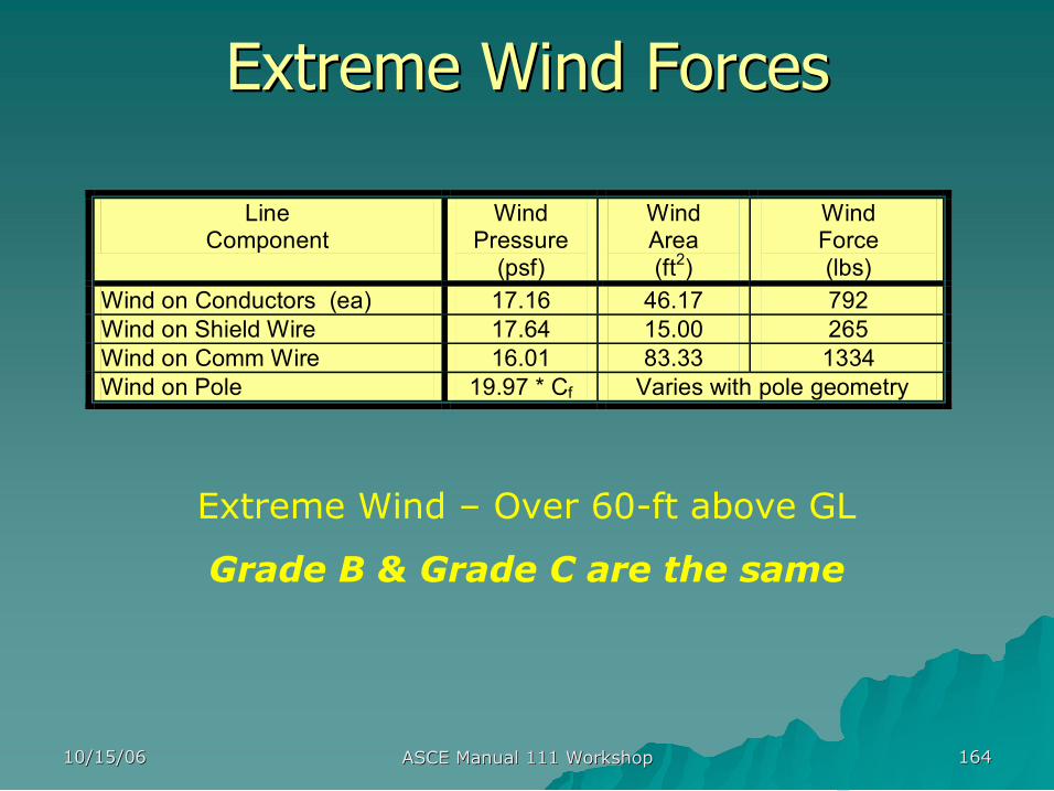
Extreme Wind Forces Extreme Wind Forces
Extreme Wind – Over 60ft above GL
Grade B & Grade C are the same
Line Component
Wind Pressure (psf)
Wind Area (ft 2 )
Wind Force (lbs)
Wind on Conductors (ea) 17.16 46.17 792 Wind on Shield Wire 17.64 15.00 265 Wind on Comm Wire 16.01 83.33 1334 Wind on Pole 19.97 * Cf Varies with pole geometry
10/15/06 10/15/06 ASCE Manual 111 Workshop ASCE Manual 111 Workshop 165 165
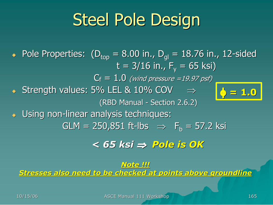
Steel Pole Design Steel Pole Design
u u Pole Properties: ( Pole Properties: (D D top top = 8.00 in., = 8.00 in., D D gl gl = 18.76 in., 12 = 18.76 in., 12 sided sided t = 3/16 in., t = 3/16 in., F F y y = 65 ksi) = 65 ksi)
C Cf f = 1.0 = 1.0 (wind pressure =19.97 psf) (wind pressure =19.97 psf)
u u Strength values: 5% LEL & 10% COV Strength values: 5% LEL & 10% COV ⇒ ⇒ ( (RBD Manual RBD Manual Section 2.6.2) Section 2.6.2)
u u Using non Using non linear analysis techniques: linear analysis techniques: GLM = 250,851 ft GLM = 250,851 ft lbs lbs ⇒ ⇒ F F b b = 57.2 ksi = 57.2 ksi
φ φ = 1.0 = 1.0
< 65 ksi < 65 ksi ⇒ ⇒ Pole is OK Pole is OK
Note !!! Note !!! Stresses also need to be checked at points above groundline Stresses also need to be checked at points above groundline
10/15/06 10/15/06 ASCE Manual 111 Workshop ASCE Manual 111 Workshop 166 166
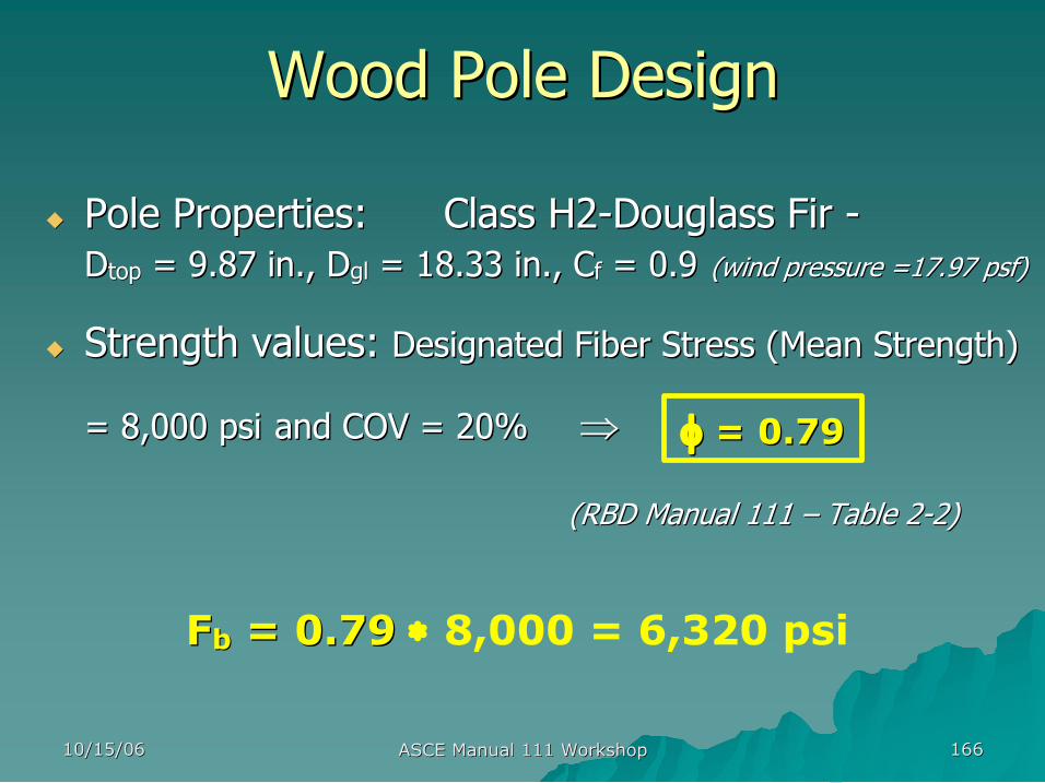
Wood Pole Design Wood Pole Design
u u Pole Properties: Class H2 Pole Properties: Class H2 Douglass Fir Douglass Fir D Dtop top = 9.87 in., = 9.87 in., D Dgl gl = 18.33 in., = 18.33 in., C Cf f = 0.9 = 0.9 (wind pressure =17.97 psf) (wind pressure =17.97 psf)
u u Strength values: Strength values: Designated Fiber Stress (Mean Strength) Designated Fiber Stress (Mean Strength)
= 8,000 = 8,000 psi psi and COV = 20% and COV = 20% ⇒ ⇒
( (RBD Manual 111 RBD Manual 111 – – Table 2 Table 2 2) 2)
φ φ = 0.79 = 0.79
F Fb b = 0.79 = 0.79 ∗ 8,000 = 6,320 psi

10/15/06 10/15/06 ASCE Manual 111 Workshop ASCE Manual 111 Workshop 167 167
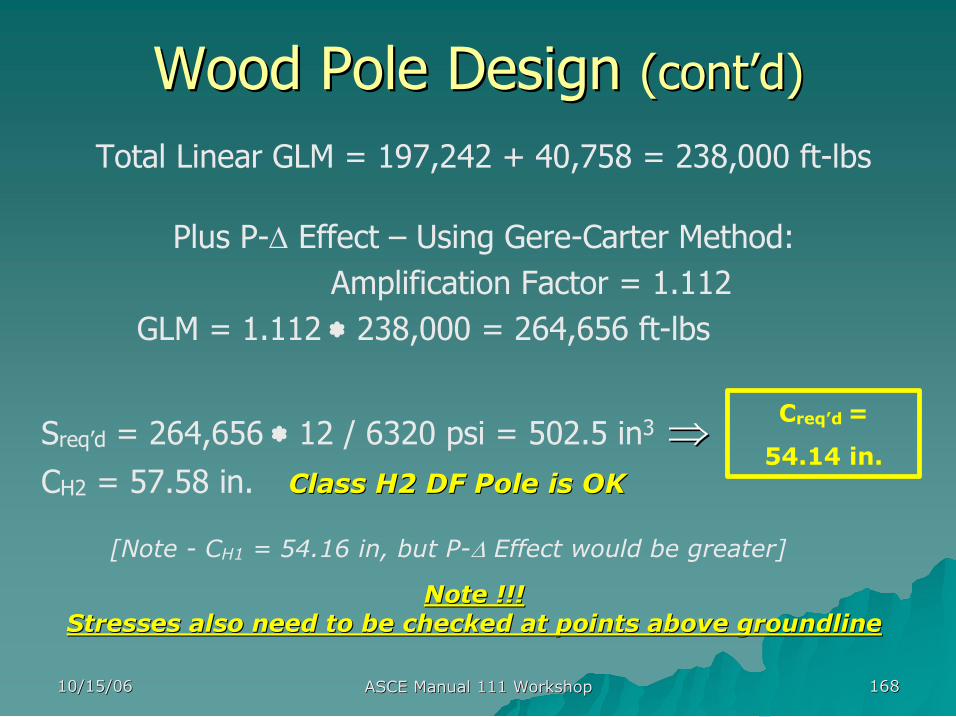
Wood Pole Design Wood Pole Design (cont (cont’ ’d) d)
u u Using linear analysis techniques: GLM = Using linear analysis techniques: GLM =
Wind on pole = 17.97 ∗ [(9.87 + 18.33)/(2 ∗ 12) ∗ 65.5] ∗ 29.47 = = 40,758 ftlbs
Total GLM = 197,242 + 40,758 = 238,000 ftlbs
Line Component
Force (lbs)
Distance (ft)
γ GLM (ftlbs)
Wind on Top Conductor 792 59.5 1.0 47,124 Wind on Middle Conductor 792 54.5 1.0 43,164 Wind on Bottom Conductor 792 49.5 1.0 39,204 Wind on Shield Wire 265 64.5 1.0 17,093 Wind on Communication Wire 1334 35.5 1.0 47,357 Conductor Eccentricity 546 5.5 1.1 3,300 Subtotal (without pole wind force) 197,242
10/15/06 10/15/06 ASCE Manual 111 Workshop ASCE Manual 111 Workshop 168 168
Wood Pole Design Wood Pole Design (cont (cont’ ’d) d)
Total Linear GLM = 197,242 + 40,758 = 238,000 ftlbs
Plus P∆ Effect – Using GereCarter Method: Amplification Factor = 1.112
GLM = 1.112 ∗ 238,000 = 264,656 ftlbs
Sreq’d = 264,656 ∗ 12 / 6320 psi = 502.5 in 3 ⇒ ⇒ CH2 = 57.58 in. Class H2 DF Pole is OK Class H2 DF Pole is OK
Note !!! Note !!! Stresses also need to be checked at points above groundline Stresses also need to be checked at points above groundline
Creq’d =
54.14 in.
[Note CH1 = 54.16 in, but P∆ Effect would be greater]
10/15/06 10/15/06 ASCE Manual 111 Workshop ASCE Manual 111 Workshop 169 169
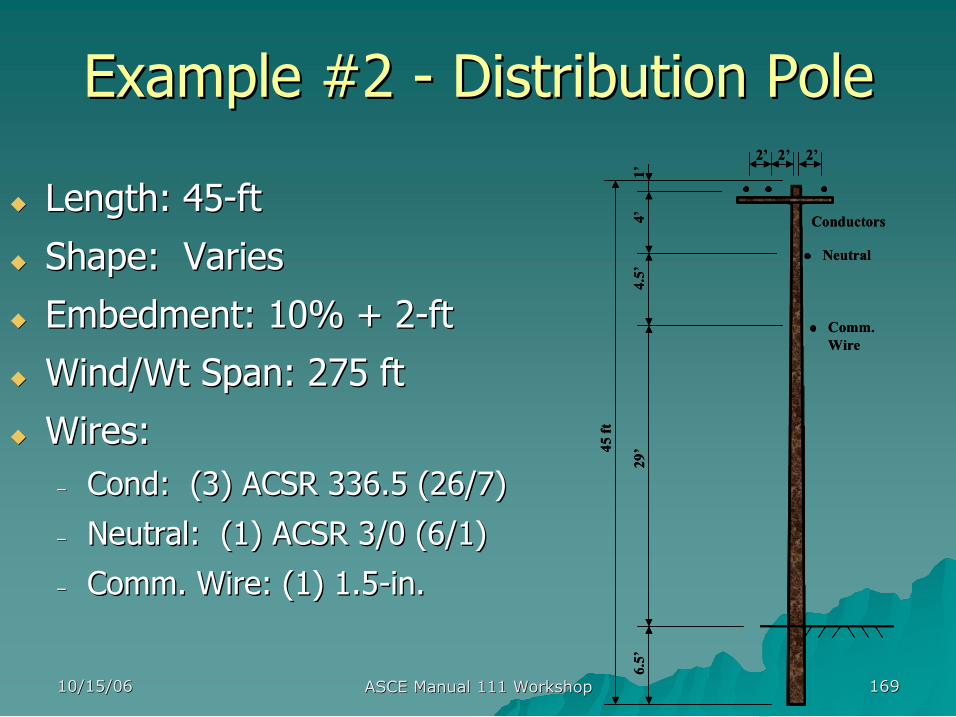
Example #2 Example #2 Distribution Pole Distribution Pole
u u Length: 45 Length: 45 ft ft
u u Shape: Varies Shape: Varies
u u Embedment: 10% + 2 Embedment: 10% + 2 ft ft
u u Wind/Wt Span: 275 ft Wind/Wt Span: 275 ft
u u Wires: Wires: – – Cond Cond: (3) ACSR 336.5 (26/7) : (3) ACSR 336.5 (26/7)
– – Neutral: (1) ACSR 3/0 (6/1) Neutral: (1) ACSR 3/0 (6/1)
– – Comm. Wire: (1) 1.5 Comm. Wire: (1) 1.5 in. in. 45 ft
4’
4.5’
1’
6.5’
29’
Conductors
Neutral
Comm. Wire
2’ 2’ 2’
45 ft
4’
4.5’
1’
6.5’
29’
Conductors
Neutral
Comm. Wire
2’ 2’ 2’
10/15/06 10/15/06 ASCE Manual 111 Workshop ASCE Manual 111 Workshop 170 170
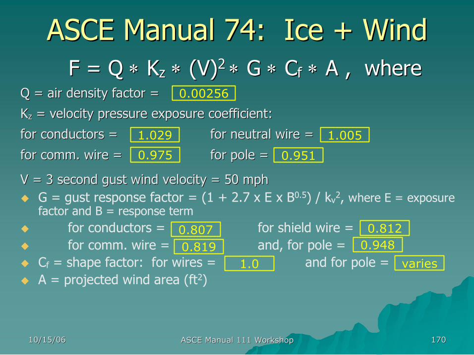
ASCE Manual 74: Ice + Wind ASCE Manual 74: Ice + Wind F = Q F = Q ∗ ∗ K Kz z ∗ ∗ (V) (V) 2 2 ∗ ∗ G G ∗ ∗ C Cf f ∗ ∗ A , where A , where
Q = air density factor = Q = air density factor =
K Kz z = velocity pressure exposure coefficient: = velocity pressure exposure coefficient:
for conductors = for conductors = for neutral wire = for neutral wire =
for comm. wire = for comm. wire = for pole = for pole =
V = 3 second gust wind velocity = 50 mph V = 3 second gust wind velocity = 50 mph u G = gust response factor = (1 + 2.7 x E x B 0.5 ) / kv 2 , where E = exposure
factor and B = response term u for conductors = for shield wire = u for comm. wire = and, for pole = u Cf = shape factor: for wires = and for pole = u A = projected wind area (ft 2 )
1.029 1.005
0.807
0.951 0.975
0.00256
0.812
0.819 0.948
1.0 varies
10/15/06 10/15/06 ASCE Manual 111 Workshop ASCE Manual 111 Workshop 171 171
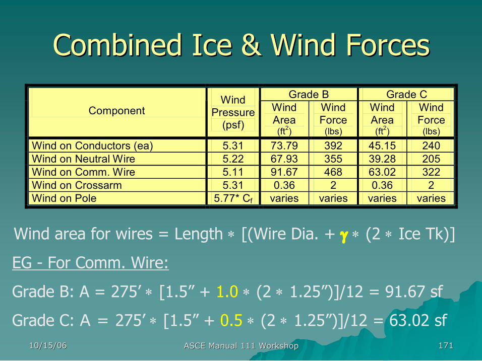
Combined Ice & Wind Forces Combined Ice & Wind Forces
Wind area for wires = Length ∗ [(Wire Dia. + γ ∗ (2 ∗ Ice Tk)]
EG For Comm. Wire:
Grade B: A = 275’ ∗ [1.5” + 1.0 ∗ (2 ∗ 1.25”)]/12 = 91.67 sf
Grade C: A = 275’ ∗ [1.5” + 0.5 ∗ (2 ∗ 1.25”)]/12 = 63.02 sf
Grade B Grade C Component
Wind Pressure (psf)
Wind Area (ft 2 )
Wind Force (lbs)
Wind Area (ft 2 )
Wind Force (lbs)
Wind on Conductors (ea) 5.31 73.79 392 45.15 240 Wind on Neutral Wire 5.22 67.93 355 39.28 205 Wind on Comm. Wire 5.11 91.67 468 63.02 322 Wind on Crossarm 5.31 0.36 2 0.36 2 Wind on Pole 5.77* Cf varies varies varies varies
10/15/06 10/15/06 ASCE Manual 111 Workshop ASCE Manual 111 Workshop 172 172
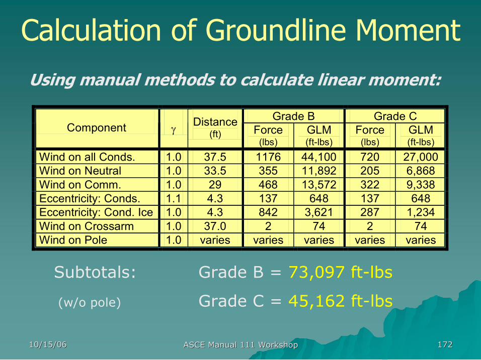
Calculation of Groundline Moment Using manual methods to calculate linear moment:
Subtotals: Grade B = 73,097 ftlbs
(w/o pole) Grade C = 45,162 ftlbs
Grade B Grade C Component γ Distance
(ft) Force (lbs)
GLM (ftlbs)
Force (lbs)
GLM (ftlbs)
Wind on all Conds. 1.0 37.5 1176 44,100 720 27,000 Wind on Neutral 1.0 33.5 355 11,892 205 6,868 Wind on Comm. 1.0 29 468 13,572 322 9,338 Eccentricity: Conds. 1.1 4.3 137 648 137 648 Eccentricity: Cond. Ice 1.0 4.3 842 3,621 287 1,234 Wind on Crossarm 1.0 37.0 2 74 2 74 Wind on Pole 1.0 varies varies varies varies varies
10/15/06 10/15/06 ASCE Manual 111 Workshop ASCE Manual 111 Workshop 173 173
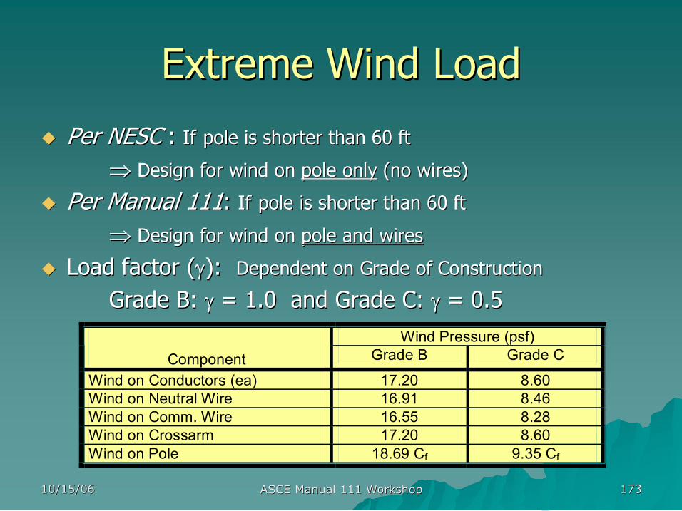
Extreme Wind Load Extreme Wind Load
Wind Pressure (psf) Component Grade B Grade C
Wind on Conductors (ea) 17.20 8.60 Wind on Neutral Wire 16.91 8.46 Wind on Comm. Wire 16.55 8.28 Wind on Crossarm 17.20 8.60 Wind on Pole 18.69 Cf 9.35 Cf
u u Per NESC Per NESC : : If If pole is shorter than 60 ft pole is shorter than 60 ft
⇒ ⇒ Design for wind on Design for wind on pole only pole only (no wires) (no wires)
u u Per Manual 111 Per Manual 111: : If If pole is shorter than 60 ft pole is shorter than 60 ft
⇒ ⇒ Design for wind on Design for wind on pole and wires pole and wires
u u Load factor ( Load factor (γ γ): ): Dependent on Grade of Construction Dependent on Grade of Construction
Grade B: Grade B: γ γ = 1.0 = 1.0 and and Grade C: Grade C: γ γ = 0.5 = 0.5
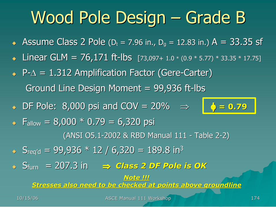
10/15/06 10/15/06 ASCE Manual 111 Workshop ASCE Manual 111 Workshop 174 174
Wood Pole Design Wood Pole Design – – Grade B Grade B u u Assume Class 2 Pole Assume Class 2 Pole ( (D Dt t = 7.96 in., D = 7.96 in., Dg g = 12.83 in.) = 12.83 in.) A = 33.35 A = 33.35 sf sf
u u Linear GLM = 76,171 ft Linear GLM = 76,171 ft lbs lbs [ [73,097+ 73,097+ 1.0 1.0 * * (0.9 * (0.9 * 5.77) 5.77) * 33.35 * 17.75] * 33.35 * 17.75]
u u P P ∆ ∆ = 1.312 Amplification Factor (Gere = 1.312 Amplification Factor (Gere Carter) Carter)
Ground Line Design Moment = 99,936 ft Ground Line Design Moment = 99,936 ft lbs lbs
u u DF Pole: 8,000 DF Pole: 8,000 psi psi and COV = 20% and COV = 20% ⇒ ⇒
u u F Fallow allow = 8,000 = 8,000 * 0.79 = 6,320 psi * 0.79 = 6,320 psi (ANSI O5.1 (ANSI O5.1 2002 & RBD Manual 111 2002 & RBD Manual 111 Table 2 Table 2 2) 2)
u u S Sreq req’’d d = 99,936 * 12 / 6,320 = 189.8 in = 99,936 * 12 / 6,320 = 189.8 in 3 3
u u S Sfurn furn = 207.3 in = 207.3 in Note !!! Note !!!
Stresses also need to be checked at points above groundline Stresses also need to be checked at points above groundline
⇒ ⇒ Class 2 DF Pole is OK Class 2 DF Pole is OK
φ φ = 0.79 = 0.79
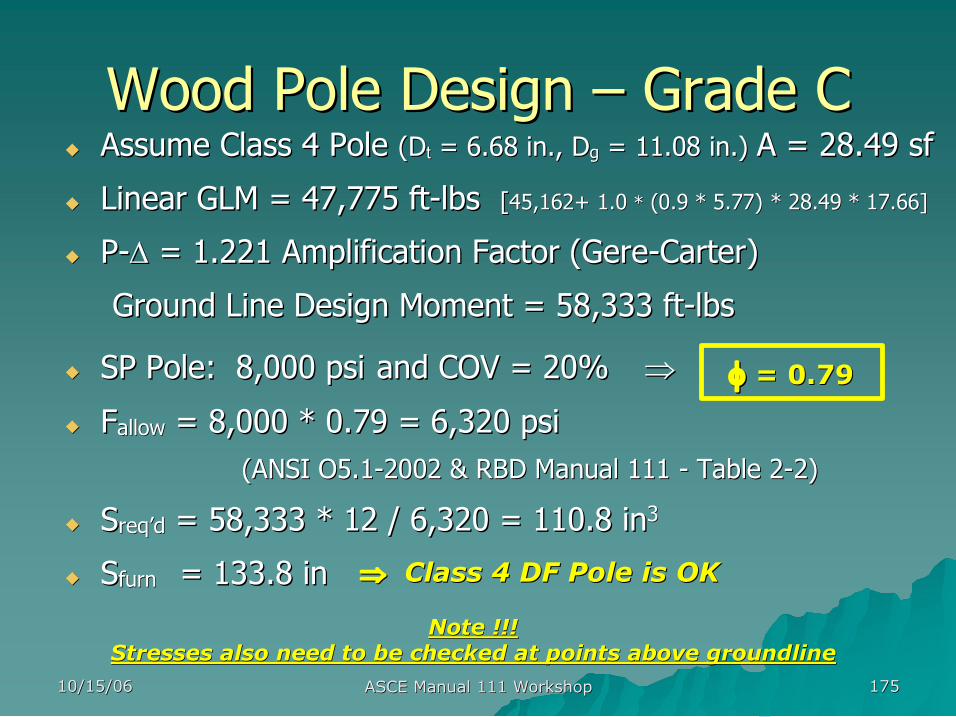
10/15/06 10/15/06 ASCE Manual 111 Workshop ASCE Manual 111 Workshop 175 175
Wood Pole Design Wood Pole Design – – Grade C Grade C u u Assume Class 4 Pole Assume Class 4 Pole ( (D Dt t = 6.68 in., D = 6.68 in., Dg g = 11.08 in.) = 11.08 in.) A = 28.49 A = 28.49 sf sf
u u Linear GLM = 47,775 ft Linear GLM = 47,775 ft lbs lbs [ [45,162+ 45,162+ 1.0 1.0 * * (0.9 * (0.9 * 5.77) 5.77) * 28.49 * 17.66] * 28.49 * 17.66]
u u P P ∆ ∆ = 1.221 Amplification Factor (Gere = 1.221 Amplification Factor (Gere Carter) Carter)
Ground Line Design Moment = 58,333 ft Ground Line Design Moment = 58,333 ft lbs lbs
u u SP Pole: 8,000 SP Pole: 8,000 psi psi and COV = 20% and COV = 20% ⇒ ⇒
u u F Fallow allow = 8,000 = 8,000 * 0.79 = 6,320 psi * 0.79 = 6,320 psi (ANSI O5.1 (ANSI O5.1 2002 & RBD Manual 111 2002 & RBD Manual 111 Table 2 Table 2 2) 2)
u u S Sreq req’’d d = 58,333 * 12 / 6,320 = 110.8 in = 58,333 * 12 / 6,320 = 110.8 in 3 3
u u S Sfurn furn = 133.8 in = 133.8 in
Note !!! Note !!! Stresses also need to be checked at points above groundline Stresses also need to be checked at points above groundline
⇒ ⇒ Class 4 DF Pole is OK Class 4 DF Pole is OK
φ φ = 0.79 = 0.79
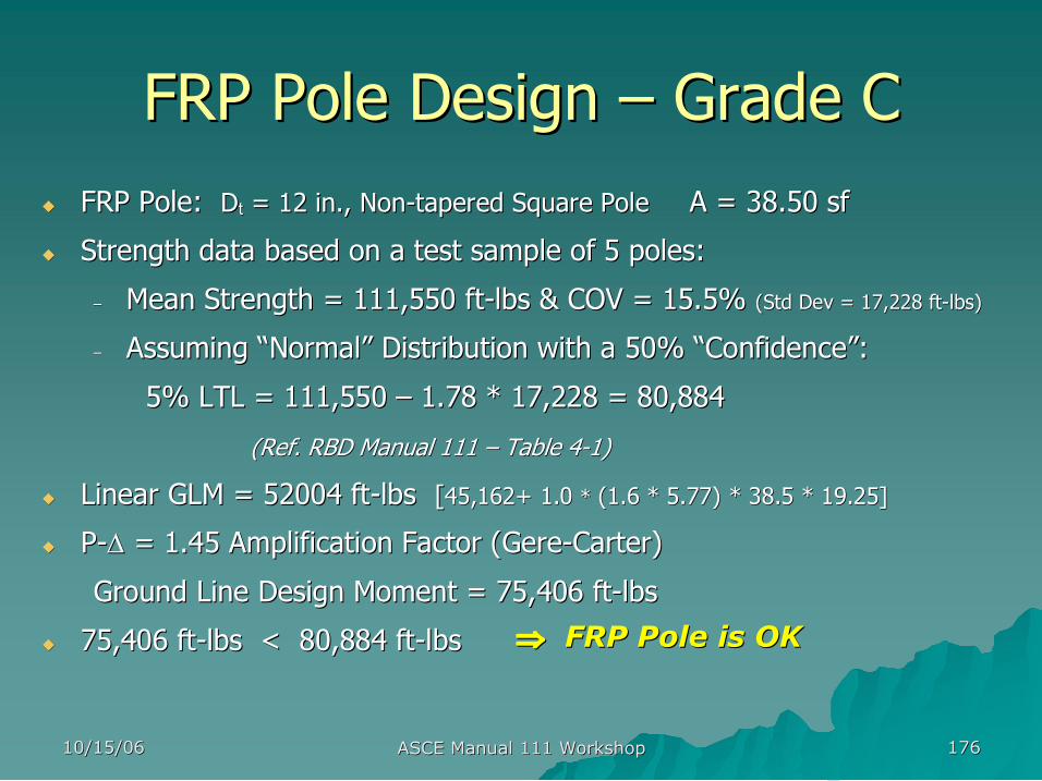
10/15/06 10/15/06 ASCE Manual 111 Workshop ASCE Manual 111 Workshop 176 176
FRP Pole Design FRP Pole Design – – Grade C Grade C u u FRP Pole: FRP Pole: D Dt t = 12 in., Non = 12 in., Non tapered Square Pole tapered Square Pole A = 38.50 A = 38.50 sf sf
u u Strength data based on a test sample of 5 poles: Strength data based on a test sample of 5 poles:
– – Mean Strength = 111,550 ft Mean Strength = 111,550 ft lbs & COV = 15.5% lbs & COV = 15.5% (Std Dev = 17,228 ft (Std Dev = 17,228 ft lbs) lbs)
– – Assuming Assuming “ “Normal Normal” ” Distribution with a 50% Distribution with a 50% “ “Confidence Confidence” ”: :
5% LTL = 111,550 5% LTL = 111,550 – – 1.78 1.78 * 17,228 = 80,884 * 17,228 = 80,884
(Ref. RBD Manual 111 (Ref. RBD Manual 111 – – Table 4 Table 4 1) 1)
u u Linear GLM = 52004 ft Linear GLM = 52004 ft lbs lbs [ [45,162+ 45,162+ 1.0 1.0 * * (1.6 * (1.6 * 5.77) 5.77) * 38.5 * 19.25] * 38.5 * 19.25]
u u P P ∆ ∆ = 1.45 Amplification Factor (Gere = 1.45 Amplification Factor (Gere Carter) Carter)
Ground Line Design Moment = 75,406 ft Ground Line Design Moment = 75,406 ft lbs lbs
u u 75,406 ft 75,406 ft lbs < 80,884 ft lbs < 80,884 ft lbs lbs ⇒ ⇒ FRP Pole is OK FRP Pole is OK
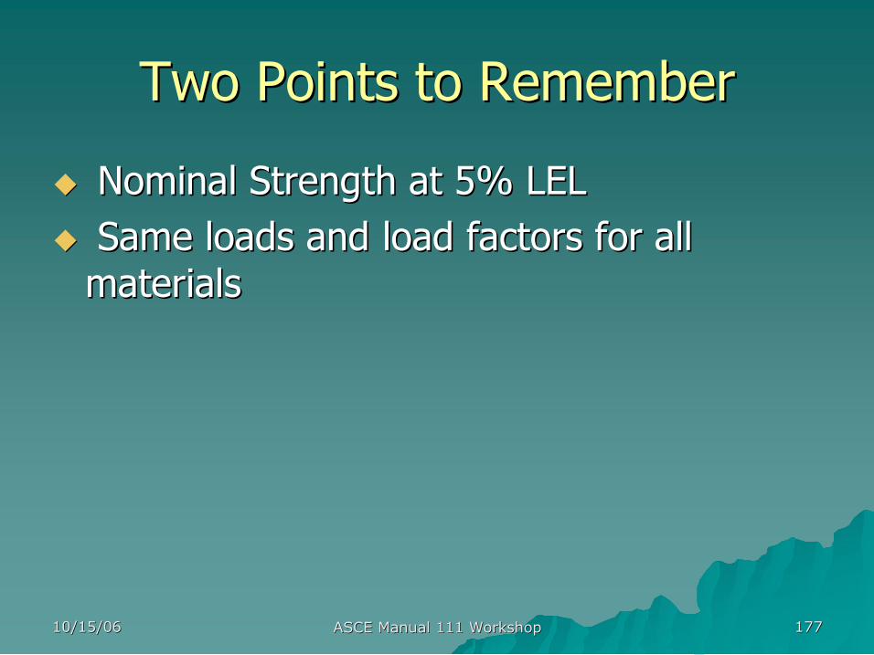
10/15/06 10/15/06 ASCE Manual 111 Workshop ASCE Manual 111 Workshop 177 177
Two Points to Remember Two Points to Remember
u u Nominal Strength at 5% LEL Nominal Strength at 5% LEL u u Same loads and load factors for all Same loads and load factors for all materials materials

10/15/06 10/15/06 ASCE Manual 111 Workshop ASCE Manual 111 Workshop 178 178
Quiz: Quiz: What strength should we use? What strength should we use? What load should we use? What load should we use?
Load Q
m Q Q 50
Strength R
m R R 5
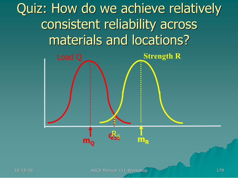
10/15/06 10/15/06 ASCE Manual 111 Workshop ASCE Manual 111 Workshop 179 179
Quiz: How do we achieve relatively Quiz: How do we achieve relatively consistent reliability across consistent reliability across materials and locations? materials and locations? Load Q
m Q Q 50
Strength R
m R R 5

10/15/06 10/15/06 ASCE Manual 111 Workshop ASCE Manual 111 Workshop 180 180