Embed Size (px)
Citation preview
Man Overboard Indicator (MOBI)TX-106 User’s Guide
ORCA TX-106 IS AMAN OVERBOARD
SYSTEM FOR COMMERCIAL APPLICATIONS

2
Supplement to SN574-AA-MMC-010 - Technical Manual for Man Overboard Indicator (MOBI) System
BriarTek, Inc. Technical Support: 703.548.7892
Email: [email protected]
Web: www.briartek.com
©2018 BriarTek. All rights reserved.
3
TABLE OF CONTENTS
Introduction 4
TX-106 Parts Overview 4
Modes 4
Operating Instructions 5
Wearing the transmitter 6
Battery Information 8
Parts List 9
Specifications 10
Warranty 11
4
Introduction
The Overboard Recovery Communications Apparatus (ORCA®) Man Overboard Indicator (MOBI) system is a personal saltwater-activated man overboard (MOB) alarm system utilized by the US Navy and other mariners. The alarm system includes a transmitter, receiver and direction finder. A DSC (digital selective calling)-capable radio is also used with the TX-106 transmitter (p/n: ORCATX-106). The TX-106 is worn on the MK-1 float coat and the inherently buoyant life preserver (IBLP) and transmits on 156.525 MHz and 121.5 MHz. When activated, it emits an RF signal which calls the DSC-capable radio. The radio sounds upon receipt of this signal, indicating the identity and GPS coordinates of the MOB. The transmitter also emits a signal which is processed by the direction finder, providing a continuous bearing to the MOB.
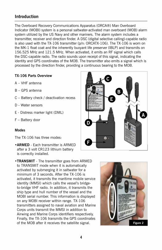
TX-106 Parts Overview
A – VHF antenna
B – GPS antenna
C – Battery check / deactivation recess
D - Water sensors
E - Distress marker light (DML)
F – Battery door
Modes
The TX-106 has three modes:
• ARMED - Each transmitter is ARMED after a 3 volt CR123 lithium battery is correctly installed.
• TRANSMIT - The transmitter goes from ARMED to TRANSMIT mode when it is automatically activated by submerging it in saltwater for a minimum of 3 seconds. After the TX-106 is activated, it transmits the maritime mobile service identity (MMSI) which calls the vessel’s bridge-to-bridge VHF radio. In addition, it transmits the ship type and hull number of the vessel and the MOBI serial number. This information is displayed on any MOBI receiver within range. TX-106 transmitters assigned to naval aviation and Marine Corps units transmit the MMSI in addition to Airwing and Marine Corps identifiers respectively. Finally, the TX-106 transmits the GPS coordinates of the MOB after it receives the satellite signal.
Figure 1
Figure 2
C
D
EB
A
F
5
A label is affixed to each transmitter displaying the above information. See Figure 2 on the previous page. After approximately 30 seconds, the transmitter switches to a non-data transmission. This enables the DF to track the transmitter more effectively. After every 15 second non-data transmission, the unit transmits identification information to the receiver for 2-3 seconds until the transmitter is deactivated (see operating instructions below).
• DISABLED - The transmitter is DISABLED when the battery is removed or the battery is depleted.
Operating Instructions
Automatic activation: The transmitter will automatically activate when the water sensors are submerged in saltwater for at least 3 seconds.
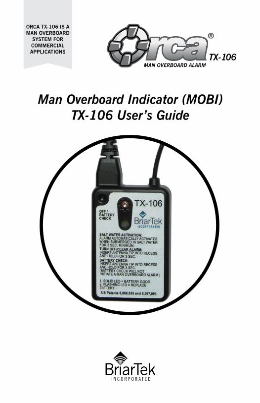
All Clear (deactivate transmitter): To deactivate the transmitter, perform one of the following options:
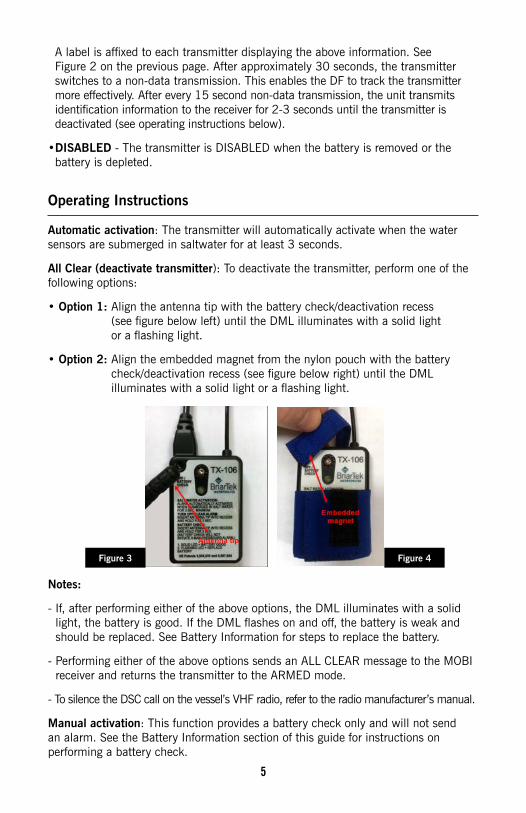
• Option 1: Align the antenna tip with the battery check/deactivation recess (see figure below left) until the DML illuminates with a solid light or a flashing light.
• Option 2: Align the embedded magnet from the nylon pouch with the battery check/deactivation recess (see figure below right) until the DML illuminates with a solid light or a flashing light.
Notes:
- If, after performing either of the above options, the DML illuminates with a solid light, the battery is good. If the DML flashes on and off, the battery is weak and should be replaced. See Battery Information for steps to replace the battery.
- Performing either of the above options sends an ALL CLEAR message to the MOBI receiver and returns the transmitter to the ARMED mode.
- To silence the DSC call on the vessel’s VHF radio, refer to the radio manufacturer’s manual.
Manual activation: This function provides a battery check only and will not send an alarm. See the Battery Information section of this guide for instructions on performing a battery check.
Figure 4Figure 3
6
Wearing the transmitter
Important: The transmitter must be worn so that the water sensors are under water and wet and the antenna is above the water surface when the person is floating.
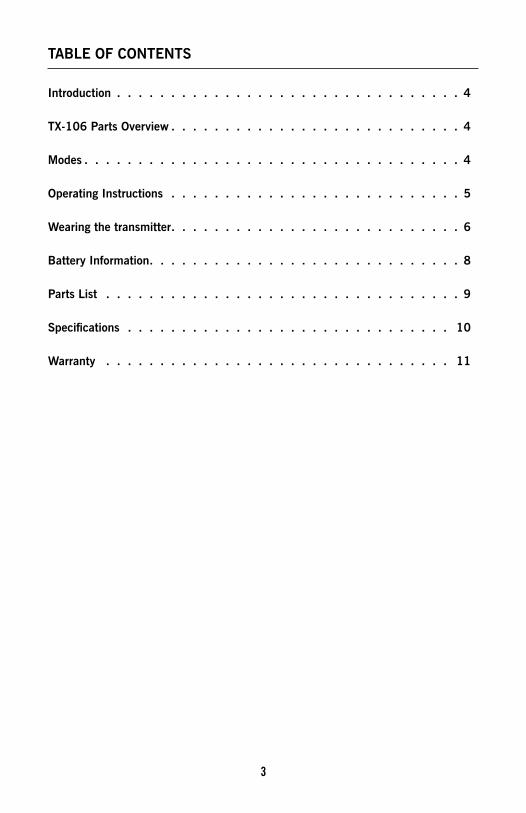
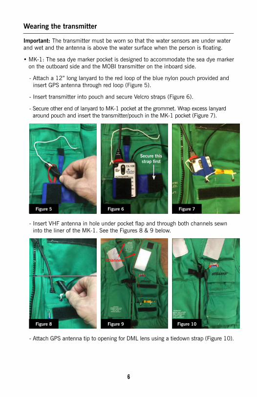
• MK-1: The sea dye marker pocket is designed to accommodate the sea dye marker on the outboard side and the MOBI transmitter on the inboard side.
- Attach a 12” long lanyard to the red loop of the blue nylon pouch provided and insert GPS antenna through red loop (Figure 5).
- Insert transmitter into pouch and secure Velcro straps (Figure 6).
- Secure other end of lanyard to MK-1 pocket at the grommet. Wrap excess lanyard around pouch and insert the transmitter/pouch in the MK-1 pocket (Figure 7).
- Insert VHF antenna in hole under pocket flap and through both channels sewn into the liner of the MK-1. See the Figures 8 & 9 below.
- Attach GPS antenna tip to opening for DML lens using a tiedown strap (Figure 10).
Figure 5
Figure 8
Figure 6
Figure 9
Figure 7
Figure 10
Secure this strap first
7
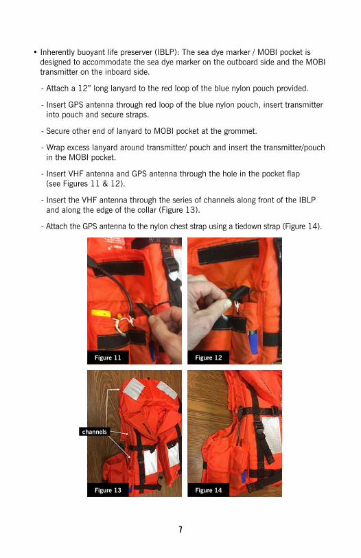
• Inherently buoyant life preserver (IBLP): The sea dye marker / MOBI pocket is designed to accommodate the sea dye marker on the outboard side and the MOBI transmitter on the inboard side.
- Attach a 12” long lanyard to the red loop of the blue nylon pouch provided.
- Insert GPS antenna through red loop of the blue nylon pouch, insert transmitter into pouch and secure straps.
- Secure other end of lanyard to MOBI pocket at the grommet.
- Wrap excess lanyard around transmitter/ pouch and insert the transmitter/pouch in the MOBI pocket.
- Insert VHF antenna and GPS antenna through the hole in the pocket flap (see Figures 11 & 12).
- Insert the VHF antenna through the series of channels along front of the IBLP and along the edge of the collar (Figure 13).
- Attach the GPS antenna to the nylon chest strap using a tiedown strap (Figure 14).
Figure 11
channels
Figure 13
Figure 12
Figure 14
8
Battery Information
Battery Lifespan: The TX-106 has low current consumption. It is recommended that the battery should be replaced once every three years and sooner if the TX-106 has been activated for more than occasional testing. When the TX-106 is in TRANSMIT mode, a new battery will last approximately 24 hours.
To test the battery strength, perform one of the following options:
- Option 1: Align the VHF antenna tip with battery check/ deactivation recess until the DML illuminates.
- Option 2: If the transmitter is being worn in the manufacturer-provided blue nylon pouch, release the pouch securing strap and align the embedded magnet with the battery check/deactivation recess until the DML illuminates.
After the DML illuminates, remove the antenna tip / embedded magnet from the recess. If the DML illuminates with a solid light, the battery is good. If the DML flashes on and off, the battery is weak and should be replaced.
Use the following steps to replace battery:
1. Using a #1 size Phillips head screwdriver, unscrew the crosshead screw on the battery door.
2. Remove battery door.
3. Remove used battery.
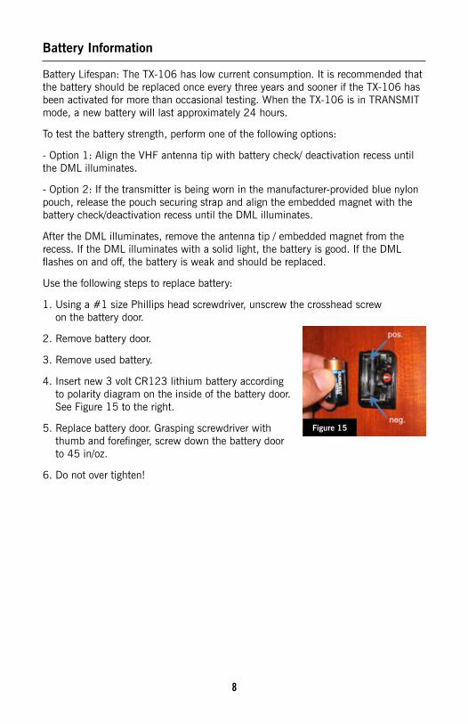
4. Insert new 3 volt CR123 lithium battery according to polarity diagram on the inside of the battery door. See Figure 15 to the right.
5. Replace battery door. Grasping screwdriver with thumb and forefinger, screw down the battery door to 45 in/oz.
6. Do not over tighten!
Figure 15
9
Parts List
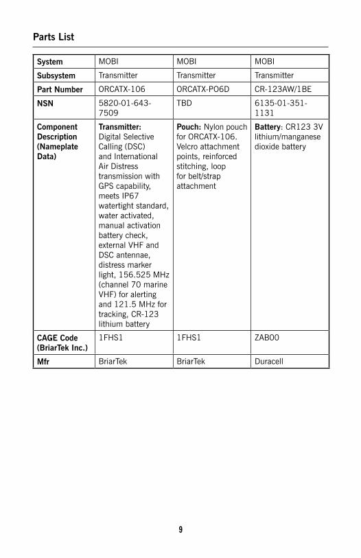
System MOBI MOBI MOBI
Subsystem Transmitter Transmitter Transmitter
Part Number ORCATX-106 ORCATX-PO6D CR-123AW/1BE
NSN 5820-01-643-7509
TBD 6135-01-351-1131
Component Description (Nameplate Data)
Transmitter: Digital Selective Calling (DSC) and International Air Distress transmission with GPS capability, meets IP67 watertight standard, water activated, manual activation battery check, external VHF and DSC antennae, distress marker light, 156.525 MHz (channel 70 marine VHF) for alerting and 121.5 MHz for tracking, CR-123 lithium battery
Pouch: Nylon pouch for ORCATX-106. Velcro attachment points, reinforced stitching, loop for belt/strap attachment
Battery: CR123 3V lithium/manganese dioxide battery
CAGE Code (BriarTek Inc )
1FHS1 1FHS1 ZAB00
Mfr BriarTek BriarTek Duracell

10
Specifications
System MOBI
Sub System Transmitters
Part Number OCRATX-106
Description TX-106 Transmitter
Weight 4 oz.
Power Source One (1) CR123 lithium battery
Battery Life One year (Armed mode); 24 hours continuous once activated (Transmit mode)
Illumination Distress marker light
Locating GPS antenna for precise location reporting
Activation Salt water
Transmit Frequencies •156.525 MHz (Channel 70 DSC-VHF) •121.5 MHz (Distress/Direction Finding)
Environmental Meets IP67 watertight standard
Operating Temperature –20ºc (–4ºF) to +55ºc (131ºF)
Storage Temperature –30ºc (–22ºF) to +70ºc (155ºF)
11
Warranty
BriarTek will provide a one-year warranty on the ORCA® MOBI system following the date of original purchase.
If a component fails to function properly during its warranty period (one year), the manufacturer will proceed according to its warranty as follows:
BriarTek Inc. guarantees each product it distributes to be free from defective materials and workmanship and agrees to remedy any such defect, or to furnish a new or equal part in exchange (at its option) for a period of one year from the date the component is purchased. For an exchange of the product, please contact BriarTek at 703-548-7892 or on the web at www.briartek.com and a customer service representative will provide the necessary instructions.
This warranty is void if:
• Any component has been subject to misuse or improper installation by a non-BriarTek employee, or has been repaired or altered by a non-BriarTek employee.
• Any component fails to function properly after being put into service due to something other than defective materials or workmanship, i.e. excessive temperature, humidity or shock while component is in storage.

San Diego, California | Alexandria, Virginia | Indianapolis, IndianaTechnical Support: 703.548.7892
www briartek com