Embed Size (px)
Citation preview
1SSMTT-27M2
GSM Option for the
E1 Module
Part of the MTT and
xDSL
Family of Products
User’s Manual
SSMTT-27M2
302 Enzo Drive San Jose, CA 95138
Tel: 1-408-363-8000 Fax: 1-408-363-8313
MAN-22060-US004 Rev C00
2 GSM for the E1 Module
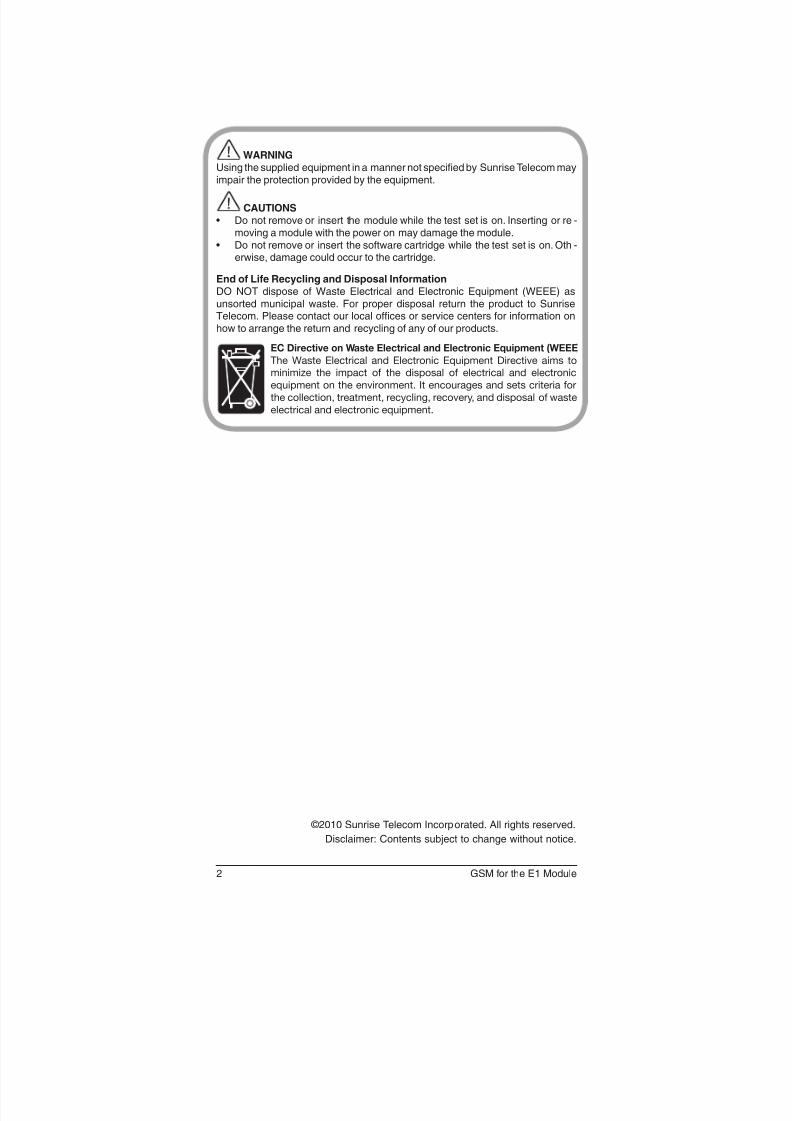
WARNINGUsing the supplied equipment in a manner not specified by Sunrise Telecom mayimpair the protection provided by the equipment.
CAUTIONS• Do not remove or insert the module while the test set is on. Inserting or re -
moving a module with the power on may damage the module.• Do not remove or insert the software cartridge while the test set is on. Oth -
erwise, damage could occur to the cartridge.
End of Life Recycling and Disposal InformationDO NOT dispose of Waste Electrical and Electronic Equipment (WEEE) asunsorted municipal waste. For proper disposal return the product to SunriseTelecom. Please contact our local offices or service centers for information onhow to arrange the return and recycling of any of our products.
EC Directive on Waste Electrical and Electronic Equipment (WEEE
The Waste Electrical and Electronic Equipment Directive aims to
minimize the impact of the disposal of electrical and electronic
equipment on the environment. It encourages and sets criteria for
the collection, treatment, recycling, recovery, and disposal of waste
electrical and electronic equipment.
©2010 Sunrise Telecom Incorporated. All rights reserved.
Disclaimer: Contents subject to change without notice.
3SSMTT-27M2
GSM for E1 Module
1 GSM Analysis Menus ....................................... 5
1.1 Abis/A-ter Channel Monitor ..............................................6
1.2 A Channel Monitor ............................................................9
1.3 Protocol Analysis ............................................................101.3.1 Configuration ...............................................................101.3.2 Protocol Analysis .........................................................12
1.3.2.1 Filter..........................................................................121.3.2.2 Capture Traces .........................................................17
1.3.3 View/Print/Save Traces ................................................18
1.4 GPRS Statistics ..............................................................221.4.1 GPRS Configuration ....................................................221.4.2 GPRS A-bis Statistics ..................................................24
1.5 TRAU Testing ..................................................................26
2 Applications .................................................... 29
2.1 A-bis Monitoring .............................................................29
3 Reference ........................................................ 31
3.1 GSM Technology Overview ............................................31
3.2 GSM Radio Transmission ...............................................33
3.3 GSM Protocol .................................................................34
3.4 TRAU Frames .................................................................36
3.5 GPRS .............................................................................38
4 General Information ........................................41
4.1 Testing and Calibration Statement ..................................41
4.2 Ofces ............................................................................41
4.3 Express Limited Warranty ...............................................43
Index ..................................................................... 45

4 GSM for the E1 Module
5SSMTT-27M2
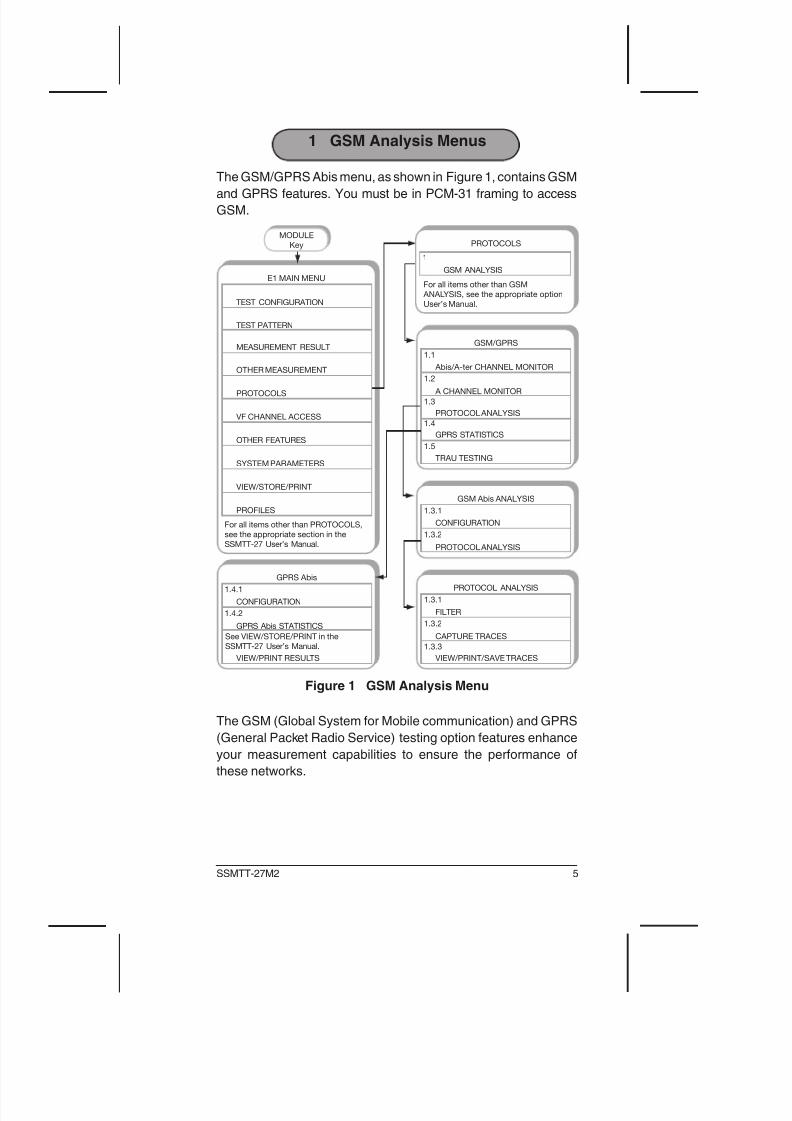
1 GSM Analysis Menus
The GSM/GPRS Abis menu, as shown in Figure 1, contains GSM
and GPRS features. You must be in PCM-31 framing to access
GSM.
PROTOCOLS
OTHER MEASUREMENT
MEASUREMENT RESULT
TEST PATTERN
TEST CONFIGURATION
VF CHANNEL ACCESS
OTHER FEATURES
SYSTEM PARAMETERS
VIEW/STORE/PRINT
PROFILES
For all items other than PROTOCOLS,
see the appropriate section in the
SSMTT-27 User’s Manual.
MODULE
Key
E1 MAIN MENU
TRAU TESTING
1.5
GSM/GPRS
GPRS STATISTICS
1.4
PROTOCOL ANALYSIS
1.3
A CHANNEL MONITOR
1.2
Abis/A-ter CHANNEL MONITOR
1.1
GSM ANALYSIS
1
PROTOCOLS
For all items other than GSM
ANALYSIS, see the appropriate option
User’s Manual.
GSM Abis ANALYSIS
PROTOCOL ANALYSIS
1.3.2
CONFIGURATION
1.3.1
GPRS Abis
GPRS Abis STATISTICS
1.4.2
CONFIGURATION
1.4.1
VIEW/PRINT RESULTS
See VIEW/STORE/PRINT in the
SSMTT-27 User’s Manual.
PROTOCOL ANALYSIS
VIEW/PRINT/SAVE TRACES
1.3.3
CAPTURE TRACES
1.3.2
FILTER
1.3.1
Figure 1 GSM Analysis Menu
The GSM (Global System for Mobile communication) and GPRS
(General Packet Radio Service) testing option features enhance
your measurement capabilities to ensure the performance of
these networks.
6 GSM for the E1 Module
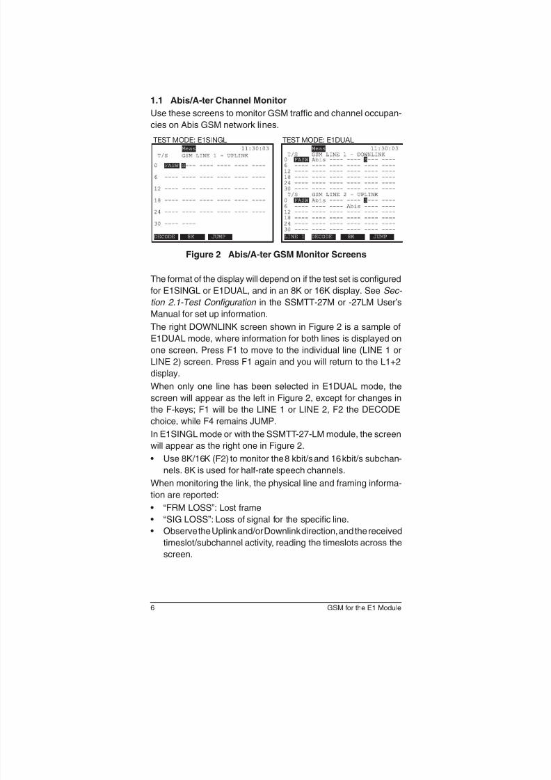
1.1 Abis/A-ter Channel Monitor
Use these screens to monitor GSM traffic and channel occupan-
cies on Abis GSM network lines.
TEST MODE: E1SINGL TEST MODE: E1DUAL
Figure 2 Abis/A-ter GSM Monitor Screens
The format of the display will depend on if the test set is congured
for E1SINGL or E1DUAL, and in an 8K or 16K display. See Sec-
tion 2.1-Test Configuration in the SSMTT-27M or -27LM User’s
Manual for set up information.
The right DOWNLINK screen shown in Figure 2 is a sample of
E1DUAL mode, where information for both lines is displayed on
one screen. Press F1 to move to the individual line (LINE 1 or
LINE 2) screen. Press F1 again and you will return to the L1+2
display.
When only one line has been selected in E1DUAL mode, the
screen will appear as the left in Figure 2, except for changes in
the F-keys; F1 will be the LINE 1 or LINE 2, F2 the DECODE
choice, while F4 remains JUMP.
In E1SINGL mode or with the SSMTT-27-LM module, the screen
will appear as the right one in Figure 2.
• Use 8K/16K (F2) to monitor the 8 kbit/s and 16 kbit/s subchan-
nels. 8K is used for half-rate speech channels.
When monitoring the link, the physical line and framing informa-
tion are reported:
• “FRM LOSS”: Lost frame
• “SIG LOSS”: Loss of signal for the specic line.
• Observe the Uplink and/or Downlink direction, and the received
timeslot/subchannel activity, reading the timeslots across the
screen.
7SSMTT-27M2
The following are screen symbol denitions:
A = 16 kbit/s signalling
Abis = 64 kbit/s signalling
E = Extended Data
D = Data
I = Idle (speech idle)
M = Operations and Maintenance
S = Speech (Full Rate, Enhanced Full Rate, Half Rate)
P = PCU (GPRS, optional)
- = Idle channel
FASW: Frame Alignment Signal Word
GSM LINE F-keys
JUMP (F3 or F4): Move between timeslots groups. Use
to move between individual timeslots. The Uplink and
Downlink channels will move simultaneously if in E1DUAL mode,
so that both sides of a single link will be monitored.
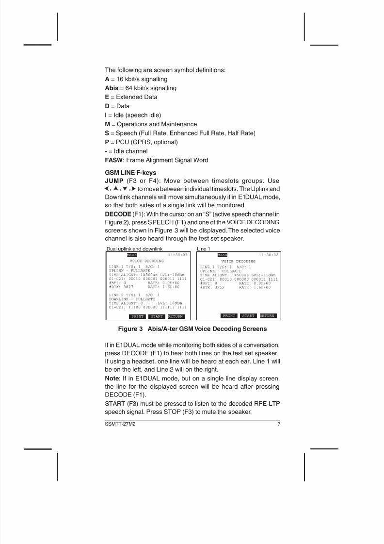
DECODE (F1): With the cursor on an “S” (active speech channel in
Figure 2), press SPEECH (F1) and one of the VOICE DECODING
screens shown in Figure 3 will be displayed. The selected voice
channel is also heard through the test set speaker.
Dual uplink and downlink Line 1
Figure 3 Abis/A-ter GSM Voice Decoding Screens
If in E1DUAL mode while monitoring both sides of a conversation,
press DECODE (F1) to hear both lines on the test set speaker.
If using a headset, one line will be heard at each ear. Line 1 will
be on the left, and Line 2 will on the right.
Note: If in E1DUAL mode, but on a single line display screen,
the line for the displayed screen will be heard after pressing
DECODE (F1).
START (F3) must be pressed to listen to the decoded RPE-LTP
speech signal. Press STOP (F3) to mute the speaker.
8 GSM for the E1 Module
The following are reported:
LINE 1/2 T/S: Line in use (1 or 2), and individual timeslot that is
being viewed.
S/C: Sub-Channel
UP/DOWNLINK: Link direction, as well as the voice encoding.
TIME ALIGNT: Time Alignment
LVL: Level of the A-law PCM voice, in dBm.
C1-C21: Overhead C-bits of the TRAU frame; displayed grouped
by the information they present.
For Uplink Decoding
#BFI: Number of Bad Fame Indicators; errored frames.
#DTX: Number of Discontinuous Transmission Mode frames;
transmitted frames not carrying data.
For Downlink Decoding
UFE: Uplink Frame Error
9SSMTT-27M2
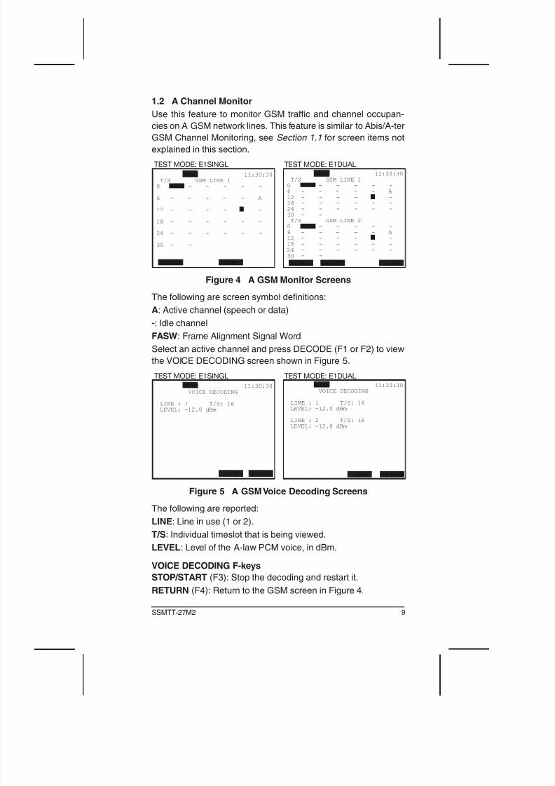
1.2 A Channel Monitor
Use this feature to monitor GSM traffic and channel occupan-
cies on A GSM network lines. This feature is similar to Abis/A-ter
GSM Channel Monitoring, see Section 1.1 for screen items not
explained in this section.
TEST MODE: E1SINGL TEST MODE: E1DUAL
MEAS 11:30:30
T/S GSM LINE 1
0 FASW - - - - -
6 - - - - - A
12 - - - - A -
18 - - - - - -
24 - - - - - -
30 - -
DECODE JUMP
MEAS 11:30:30
T/S GSM LINE 1
0 FASW - - - - -
6 - - - - - A
12 - - - - A -
18 - - - - - -
24 - - - - - -
30 - -
T/S GSM LINE 2
0 FASW - - - - -
6 - - - - - A
12 - - - - A -
18 - - - - - -
24 - - - - - -
30 - -
LINE 1 DECODE JUMP
Figure 4 A GSM Monitor Screens
The following are screen symbol denitions:
A: Active channel (speech or data)
-: Idle channel
FASW: Frame Alignment Signal Word
Select an active channel and press DECODE (F1 or F2) to view
the VOICE DECODING screen shown in Figure 5.
TEST MODE: E1SINGL TEST MODE: E1DUAL
MEAS 11:30:30
VOICE DECODING
LINE : 1 T/S: 16
LEVEL: -12.0 dBm
STOP RETURN
MEAS 11:30:30
VOICE DECODING
LINE : 1 T/S: 16
LEVEL: -12.0 dBm
LINE : 2 T/S: 16
LEVEL: -12.0 dBm
STOP RETURN
Figure 5 A GSM Voice Decoding Screens
The following are reported:
LINE: Line in use (1 or 2).
T/S: Individual timeslot that is being viewed.
LEVEL: Level of the A-law PCM voice, in dBm.
VOICE DECODING F-keys
STOP/START (F3): Stop the decoding and restart it.
RETURN (F4): Return to the GSM screen in Figure 4.
10 GSM for the E1 Module
1.3 Protocol Analysis
This menu screen contains the following:
• CONFIGURATION
• PROTOCOL ANALYSIS
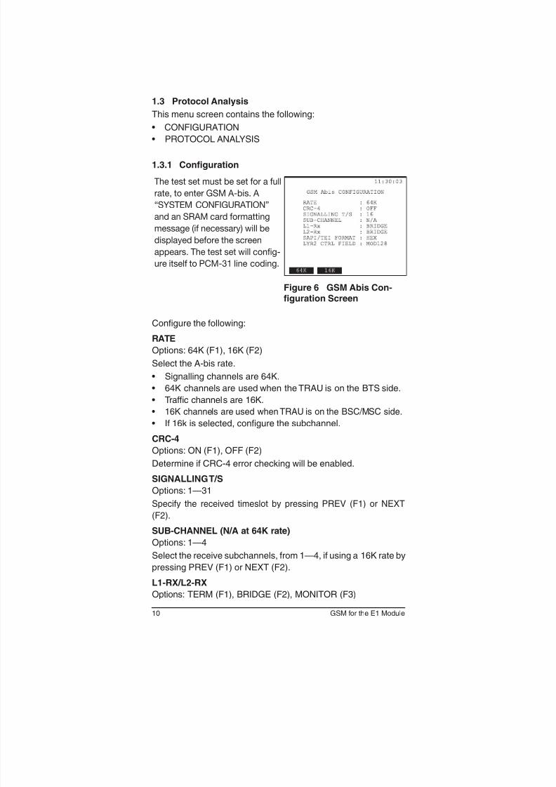
1.3.1 Configuration
The test set must be set for a full
rate, to enter GSM A-bis. A
“SYSTEM CONFIGURATION”
and an SRAM card formatting
message (if necessary) will be
displayed before the screen
appears. The test set will config-
ure itself to PCM-31 line coding.
Figure 6 GSM Abis Con-figuration Screen
Congure the following:
RATE
Options: 64K (F1), 16K (F2)
Select the A-bis rate.
• Signalling channels are 64K.
• 64K channels are used when the TRAU is on the BTS side.
• Trafc channels are 16K.
• 16K channels are used when TRAU is on the BSC/MSC side.
• If 16k is selected, congure the subchannel.
CRC-4
Options: ON (F1), OFF (F2)
Determine if CRC-4 error checking will be enabled.
SIGNALLING T/S
Options: 1—31
Specify the received timeslot by pressing PREV (F1) or NEXT
(F2).
SUB-CHANNEL (N/A at 64K rate)
Options: 1—4
Select the receive subchannels, from 1—4, if using a 16K rate by
pressing PREV (F1) or NEXT (F2).
L1-RX/L2-RX
Options: TERM (F1), BRIDGE (F2), MONITOR (F3)
11SSMTT-27M2
Specify the line interface mode for testing.
• TERM: Used when sending and receiving an E1 signal. It is
the most common mode used for out-of-service testing. The
test set terminates the received signal with a low impedance
termination, and requires that the circuit be disrupted for testing.
A 75Ω termination is used for BNC and 1.6/5.6 mm connec -
tors. A 120Ω termination is used for BR2 and 3-pin banana
connectors.
• BRIDGE: This is similar to Monitor mode. However, in Bridge
mode, the test set applies high impedance isolation resistors to
the circuit under test. This protects the signal from disruptions. It
is most commonly used for testing live circuits.
Note if connecting to the circuit through a MON jack to the
test set while in Bridge mode, this can result in two isolation
circuits on the signal. This may cause the test set to report a
loss of signal and be unable to perform measurements.
• MONITOR: Used for monitoring from a protected monitoring
point. The signal is provided from the MON jack of an E1 network
element. The network element has isolated the monitor signal
from the live signal with high impedance resistors. The test set
has an AGC (Automatic Gain Control) circuit to compensate for
the resistive loss of -15 dB to -30 dB. If the signal source is not
a resistively attenuated monitor output signal, the AGC will not
operate properly, and as a result, code error and/or other problem
indicators will be shown on the test set.
This mode is useful because it protects the live signal from
possible disruptions caused by the testing process. It allows
observing the line while the circuit is operational.
SAPI /TEI FORMAT
Options: HEX (F1), DECIMAL (F2)
Select the formatting of the SAPI and TEI.
LYR2 CTRL FIELD
Options: MOD8 (F1), MOD128 (F2)
Select the Layer 2 control field.
• MOD8: Modulo 8 sequence numbering.
• MOD128: Modulo 128 sequence numbering, the ETSI speci-
fied method.
12 GSM for the E1 Module
1.3.2 Protocol Analysis
This menu screen contains the following selections:
• FILTER
• CAPTURE TRACES
• VIEW/PRINT/SAVE TRACES
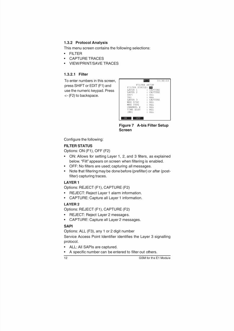
1.3.2.1 Filter
To enter numbers in this screen,
press SHIFT or EDIT (F1) and
use the numeric keypad. Press
<- (F2) to backspace.
Figure 7 A-bis Filter Setup
Screen
Congure the following:
FILTER STATUS
Options: ON (F1), OFF (F2)
• ON: Allows for setting Layer 1, 2, and 3 lters, as explained
below. “Filt” appears on screen when ltering is enabled.
• OFF: No lters are used; capturing all messages.
• Note that ltering may be done before (prelter) or after (post-
lter) capturing traces.
LAYER 1
Options: REJECT (F1), CAPTURE (F2)
• REJECT: Reject Layer 1 alarm information.
• CAPTURE: Capture all Layer 1 information.
LAYER 2
Options: REJECT (F1), CAPTURE (F2)
• REJECT: Reject Layer 2 messages.
• CAPTURE: Capture all Layer 2 messages.
SAPI
Options: ALL (F3), any 1 or 2 digit number
Service Access Point Identier identies the Layer 3 signalling
protocol.
• ALL: All SAPIs are captured.
• A specic number can be entered to lter out others.
13SSMTT-27M2
TEI
Options: ALL (F3), any 1 or 2 digit number
Terminal Endpoint Identier identies the TRX. TEI values 0—63
(00—3F, hex) are reserved for xed addresses. Values 64—126
(40—7E, hex) are used for additional addresses to TRXs needing
more than one signalling l ink.
• ALL: All TEIs are captured.
• A specic number can bee entered to lter out others.
LAYER 3
Options: REJECT (F1), CAPTURE (F2)
• REJECT: Press to reject Layer 3 messages.
• CAPTURE: Press to capture Layer 3 messages.
MSG DISC
Options: ALL (F1), RLL_MGT (F2), DC_MGT (F3), CC_MGT
(more, F1), TRX_MGT (more, F2), RESERVD (more, F3)
The Message Discriminator allows for discriminating between RRL
(Radio Link), DC (Dedicated Channel), CC (Common Channel),
and TRX management. Reserved messages are reserved for
future use; they may be proprietary to their constructors, reserved
for the government, etc.
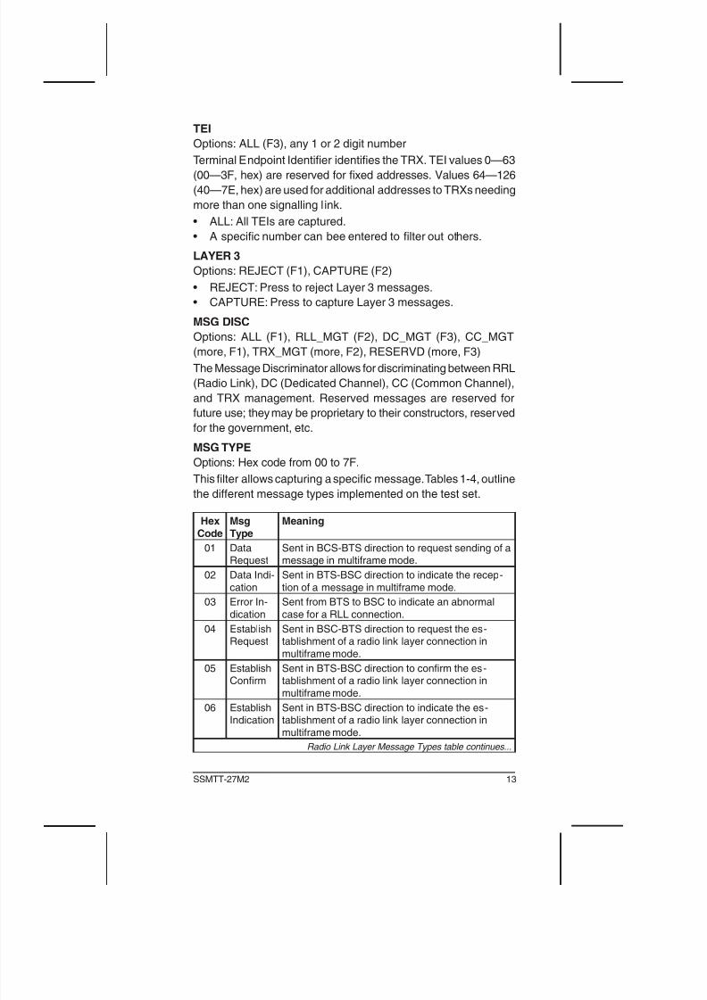
MSG TYPE
Options: Hex code from 00 to 7F.
This lter allows capturing a specic message. Tables 1-4, outline
the different message types implemented on the test set.
Hex
Code
Msg
Type
Meaning
01 DataRequest
Sent in BCS-BTS direction to request sending of amessage in multiframe mode.
02 Data Indi-
cation
Sent in BTS-BSC direction to indicate the recep-
tion of a message in multiframe mode.
03 Error In-
dication
Sent from BTS to BSC to indicate an abnormal
case for a RLL connection.
04 EstablishRequest
Sent in BSC-BTS direction to request the es-tablishment of a radio link layer connection in
multiframe mode.
05 EstablishConfirm
Sent in BTS-BSC direction to conrm the es-tablishment of a radio link layer connection in
multiframe mode.
06 EstablishIndication
Sent in BTS-BSC direction to indicate the es-tablishment of a radio link layer connection in
multiframe mode.
Radio Link Layer Message Types table continues...
14 GSM for the E1 Module
HexCode
MsgType
Meaning
07 Release
Request
Sent in BSC-BTS direction to request the release
of a radio link layer connection in multiframemode.
08 Release
Confirm
Sent in BTS-BSC direction to conrm the release
of radio link connection in multiframe mode.
09 ReleaseIndication
Sent in BTS-BSC direction to indicate the releaseof a radio link layer connection in multiframe
mode.
0A Unit DataRequest
Sent in BSC-BTS direction to request the send-ing of a message in unacknowledged mode on a
radio link layer connection.
0B Unit DataIndication
Sent in BTS-BSC direction to indicate the recep-tion of a message in unacknowldeged mode on a
radio link layer connection.
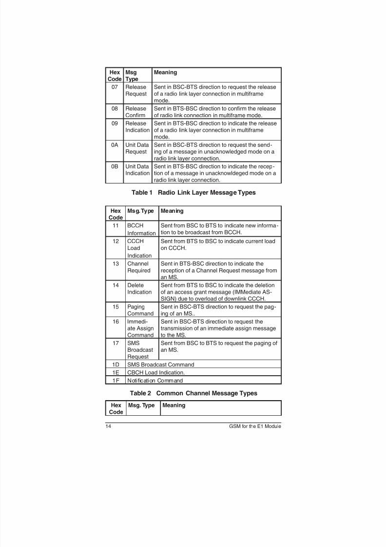
Table 1 Radio Link Layer Message Types
HexCode
Msg. Type Meaning
11 BCCH
Information
Sent from BSC to BTS to indicate new informa-
tion to be broadcast from BCCH.
12 CCCH
Load
Indication
Sent from BTS to BSC to indicate current load
on CCCH.
13 Channel
Required
Sent in BTS-BSC direction to indicate the
reception of a Channel Request message froman MS.
14 Delete
Indication
Sent from BTS to BSC to indicate the deletion
of an access grant message (IMMediate AS-SIGN) due to overload of downlink CCCH.
15 Paging
Command
Sent in BSC-BTS direction to request the pag-
ing of an MS..
16 Immedi-ate Assign
Command
Sent in BSC-BTS direction to request thetransmission of an immediate assign message
to the MS.
17 SMSBroadcast
Request
Sent from BSC to BTS to request the paging ofan MS.
1D SMS Broadcast Command
1E CBCH Load Indication.
1F Notification Command
Table 2 Common Channel Message Types
Hex
Code
Msg. Type Meaning
15SSMTT-27M2
19 RFResource
Indication
Sent from BTS to BSC to indicate the interfer-ence level on idle channels of a TRX.
1A SACCHFilling
Sent in BSC-BTS direction to indicate the newbroadcast information to be used as filling
information on SACCH.
1B Overload Sent in BTS-BSC direction to indicate an over-load situation.
1C Error
Report
Sent from BTS to BSC to report a detected errorthat can’t be reported in any other message.
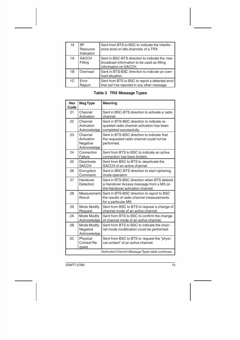
Table 3 TRX Message Types
HexCode
Msg Type Meaning
21 Channel
Activation
Sent in BSC-BTS direction to activate a radio
channel.
22 ChannelActivation
Acknowledge
Sent in BTS-BSC direction to indicate re-quested radio channel activation has been
completed successfully.
23 ChannelActivation
Negative
Acknowledge
Sent in BTS-BSC direction to indicate thatthe requested radio channel could not be
performed.
24 Connection
Failure
Sent from BTS to BSC to indicate an active
connection has been broken.
25 DeactivateSACCH
Sent from BSC to BTS to deactivate theSACCH of an active channel.
26 Encryption
Command
Sent in BSC-BTS direction to start ciphering
mode operation
27 HandoverDetection
Sent in BTS-BSC direction when BTS detectsa Handover Access message from a MS on
the Handover activation channel.
28 MeasurementResult
Sent in BTS-BSC direction to report to BSCthe results of radio channel measurements
for a particular MS.
29 Mode ModifyRequest
Sent from BSC to BTS to request a change ofchannel mode of an active channel.
2A Mode Modify
Acknowledge
Sent from BTS to BSC to conrm the change
of channel mode of an active channel.
2B Mode ModifyNegative
Acknowledge
Sent from BTS to BSC to indicate the chan -nel mode modification could be performed.
2C PhysicalContext Re-
quest
Sent from BSC to BTS to request the “physi-cal context” of an active channel.
Dedicated Channel Message Types table continues...
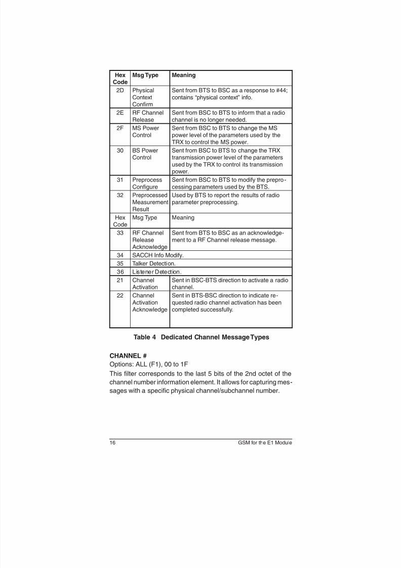
16 GSM for the E1 Module
HexCode
Msg Type Meaning
2D Physical
ContextConfirm
Sent from BTS to BSC as a response to #44;
contains “physical context” info.
2E RF Channel
Release
Sent from BSC to BTS to inform that a radio
channel is no longer needed.
2F MS PowerControl
Sent from BSC to BTS to change the MSpower level of the parameters used by the
TRX to control the MS power.
30 BS PowerControl
Sent from BSC to BTS to change the TRXtransmission power level of the parameters
used by the TRX to control its transmissionpower.
31 Preprocess
Configure
Sent from BSC to BTS to modify the prepro -
cessing parameters used by the BTS.
32 Preprocessed Measurement
Result
Used by BTS to report the results of radioparameter preprocessing.
HexCode
Msg Type Meaning
33 RF Channel
ReleaseAcknowledge
Sent from BTS to BSC as an acknowledge-
ment to a RF Channel release message.
34 SACCH Info Modify.
35 Talker Detection.
36 Listener Detection.
21 ChannelActivation
Sent in BSC-BTS direction to activate a radiochannel.
22 Channel
ActivationAcknowledge
Sent in BTS-BSC direction to indicate re-
quested radio channel activation has beencompleted successfully.
Table 4 Dedicated Channel Message Types
CHANNEL #
Options: ALL (F1), 00 to 1F
This filter corresponds to the last 5 bits of the 2nd octet of the
channel number information element. It allows for capturing mes-
sages with a specic physical channel/subchannel number.
17SSMTT-27M2
TIMESLOT
Options: ALL (F1), 0 to 7
Capture messages using a specic timeslot number. It corre-
sponds to the first three bits of the second octet of the channel
number information element.
IMSI
Options: ALL (F1), any up to ten digit number
Choose whether to lter for messages containing the International
Mobile Subscriber Identity information.
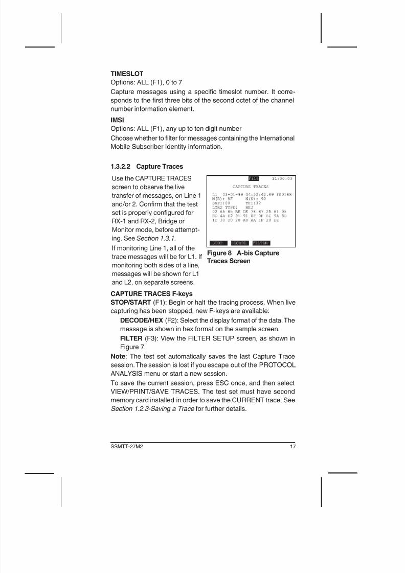
1.3.2.2 Capture Traces
Use the CAPTURE TRACES
screen to observe the live
transfer of messages, on Line 1
and/or 2. Confirm that the test
set is properly configured for
RX-1 and RX-2, Bridge or
Monitor mode, before attempt-
ing. See Section 1.3.1.
If monitoring Line 1, all of the
trace messages will be for L1. If
monitoring both sides of a line,
messages will be shown for L1
and L2, on separate screens.
Figure 8 A-bis Capture
Traces Screen
CAPTURE TRACES F-keys
STOP/START (F1): Begin or halt the tracing process. When live
capturing has been stopped, new F-keys are available:
DECODE/HEX (F2): Select the display format of the data. The
message is shown in hex format on the sample screen.
FILTER (F3): View the FILTER SETUP screen, as shown in
Figure 7.
Note: The test set automatically saves the last Capture Trace
session. The session is lost if you escape out of the PROTOCOL
ANALYSIS menu or start a new session.
To save the current session, press ESC once, and then select
VIEW/PRINT/SAVE TRACES. The test set must have second
memory card installed in order to save the CURRENT trace. See
Section 1.2.3-Saving a Trace for further details.
18 GSM for the E1 Module
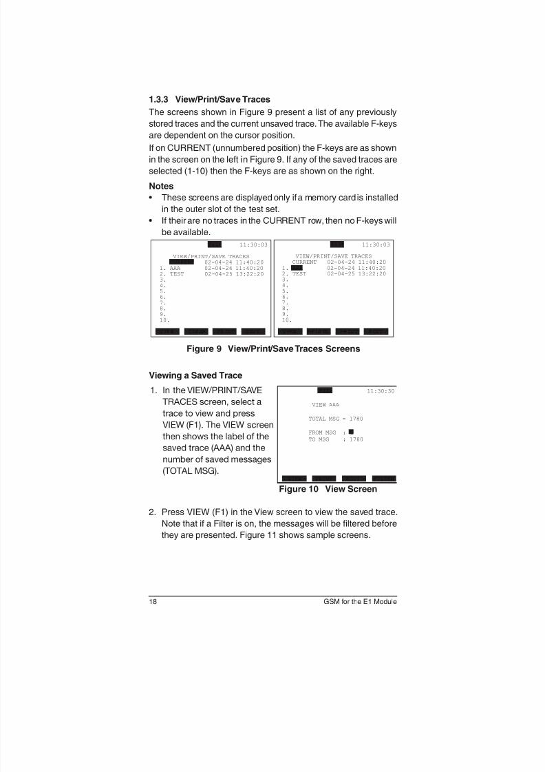
1.3.3 View/Print/Save Traces
The screens shown in Figure 9 present a list of any previously
stored traces and the current unsaved trace. The available F-keys
are dependent on the cursor position.
If on CURRENT (unnumbered position) the F-keys are as shown
in the screen on the left in Figure 9. If any of the saved traces are
selected (1-10) then the F-keys are as shown on the right.
Notes
• These screens are displayed only if a memory card is installed
in the outer slot of the test set.
• If their are no traces in the CURRENT row, then no F-keys will
be available.
Figure 9 View/Print/Save Traces Screens
Viewing a Saved Trace
1. In the VIEW/PRINT/SAVE
TRACES screen, select a
trace to view and press
VIEW (F1). The VIEW screen
then shows the label of the
saved trace (AAA) and the
number of saved messages
(TOTAL MSG).
Filt 11:30:30
VIEW AAA
TOTAL MSG = 1780
FROM MSG : 1
TO MSG : 1780
VIEW PRINT EDIT FILTER
Figure 10 View Screen
2. Press VIEW (F1) in the View screen to view the saved trace.
Note that if a Filter is on, the messages will be ltered before
they are presented. Figure 11 shows sample screens.
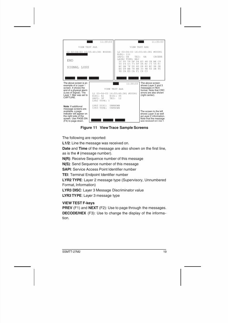
19SSMTT-27M2
Figure 11 View Trace Sample Screens
The following are reported:
L1/2: Line the message was received on.
Date and Time of the message are also shown on the rst line,
as is the # (message number).
N(R): Receive Sequence number of this message
N(S): Send Sequence number of this message
SAPI: Service Access Point Identier number
TEI: Terminal Endpoint Identier number
LYR2 TYPE: Layer 2 message type (Supervisory, Unnumbered
Format, Information)
LYR3 DISC: Layer 3 Message Discriminator value
LYR3 TYPE: Layer 3 message type
VIEW TEST F-keys
PREV (F1) and NEXT (F2): Use to page through the messages.
DECODE/HEX (F3): Use to change the display of the informa-
tion.
20 GSM for the E1 Module
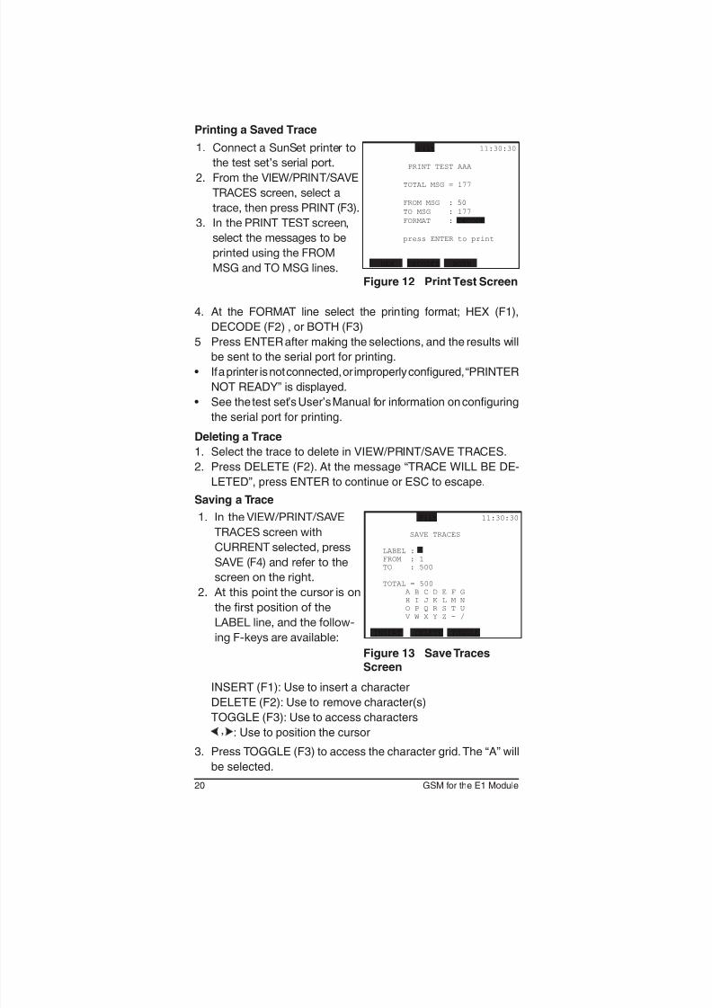
Printing a Saved Trace
1. Connect a SunSet printer to
the test set’s serial port.
2. From the VIEW/PRINT/SAVE
TRACES screen, select a
trace, then press PRINT (F3).
3. In the PRINT TEST screen,
select the messages to be
printed using the FROM
MSG and TO MSG lines.
Filt 11:30:30
PRINT TEST AAA
TOTAL MSG = 177
FROM MSG : 50
TO MSG : 177
FORMAT : DECODE
press ENTER to print
HEX DECODED BOTH
Figure 12 Print Test Screen
4. At the FORMAT line select the printing format; HEX (F1),
DECODE (F2) , or BOTH (F3)
5 Press ENTER after making the selections, and the results will
be sent to the serial port for printing.
• If a printer is not connected, or improperly congured, “PRINTER
NOT READY” is displayed.
• See the test set’s User’s Manual for information on conguring
the serial port for printing.
Deleting a Trace
1. Select the trace to delete in VIEW/PRINT/SAVE TRACES.
2. Press DELETE (F2). At the message “TRACE WILL BE DE-
LETED”, press ENTER to continue or ESC to escape.
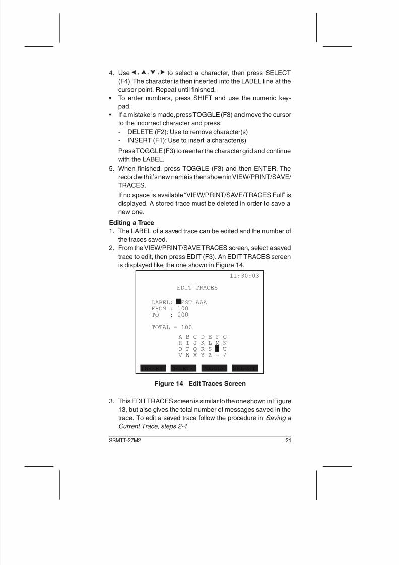
Saving a Trace
1. In the VIEW/PRINT/SAVE
TRACES screen with
CURRENT selected, press
SAVE (F4) and refer to the
screen on the right.
2. At this point the cursor is on
the first position of the
LABEL line, and the follow-
ing F-keys are available:
Filt 11:30:30
SAVE TRACES
LABEL :
FROM : 1
TO : 500
TOTAL = 500
A B C D E F G
H I J K L M N
O P Q R S T U
V W X Y Z - /
INSERT DELETE TOGGLE
Figure 13 Save TracesScreen
INSERT (F1): Use to insert a character
DELETE (F2): Use to remove character(s)
TOGGLE (F3): Use to access characters
: Use to position the cursor
3. Press TOGGLE (F3) to access the character grid. The “A” will
be selected.
21SSMTT-27M2
4. Use to select a character, then press SELECT
(F4). The character is then inserted into the LABEL line at the
cursor point. Repeat until finished.
• To enter numbers, press SHIFT and use the numeric key-
pad.
• If a mistake is made, press TOGGLE (F3) and move the cursor
to the incorrect character and press:
- DELETE (F2): Use to remove character(s)
- INSERT (F1): Use to insert a character(s)
Press TOGGLE (F3) to reenter the character grid and continue
with the LABEL.
5. When nished, press TOGGLE (F3) and then ENTER. The
record with it’s new name is then shown in VIEW/PRINT/SAVE/
TRACES.
If no space is available “VIEW/PRINT/SAVE/TRACES Full” is
displayed. A stored trace must be deleted in order to save a
new one.
Editing a Trace
1. The LABEL of a saved trace can be edited and the number of
the traces saved.
2. From the VIEW/PRINT/SAVE TRACES screen, select a saved
trace to edit, then press EDIT (F3). An EDIT TRACES screen
is displayed like the one shown in Figure 14.
Figure 14 Edit Traces Screen
3. This EDIT TRACES screen is similar to the one shown in Figure
13, but also gives the total number of messages saved in the
trace. To edit a saved trace follow the procedure in Saving a
Current Trace, steps 2-4 .
22 GSM for the E1 Module
1.4 GPRS Statistics
The General Packet Radio Service Statistics feature enhances
the measurement capabilities for confirming the performance of a
GPRS network, including GPRS over GSM Abis. GPRS Analysis
conforms to ETSI Recommendations for GSM Phase 2+GSM
04.08,GSM 08.56, and GSM 08.58.
In order to use the GPRS functions, set the E1 module’s Test
Conguration L1-Rx and L2-Rx to Bridge or Monitor.
The GPRS Abis menu screen contains the following:
• CONFIGURATION
• GPRS Abis STATISTICS
• VIEW/PRINT RESULTS (see VIEW/STORE/PRINT in the
SSMTT-27 User’s Manual .
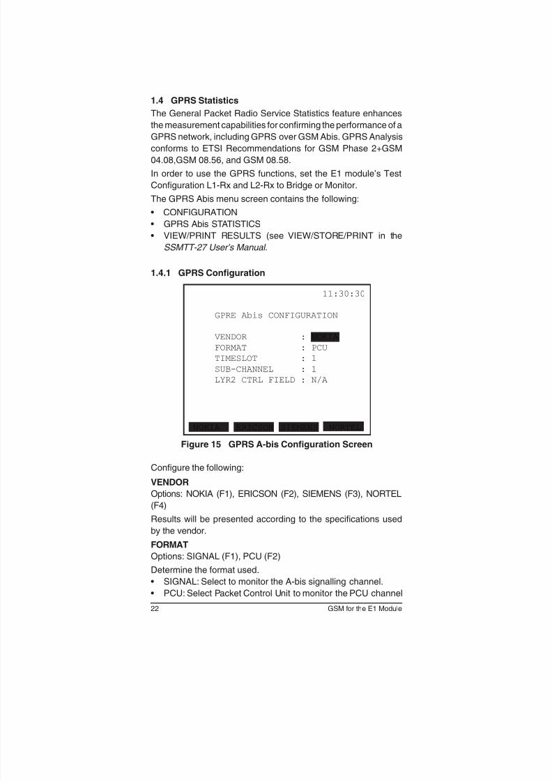
1.4.1 GPRS Configuration
11:30:30
GPRE Abis CONFIGURATION
VENDOR : NOKIA
FORMAT : PCU
TIMESLOT : 1
SUB-CHANNEL : 1
LYR2 CTRL FIELD : N/A
NOKIA ERICSON SIEMENS NORTEL
Figure 15 GPRS A-bis Configuration Screen
Congure the following:
VENDOR
Options: NOKIA (F1), ERICSON (F2), SIEMENS (F3), NORTEL
(F4)
Results will be presented according to the specications used
by the vendor.
FORMAT
Options: SIGNAL (F1), PCU (F2)
Determine the format used.
• SIGNAL: Select to monitor the A-bis signalling channel.
• PCU: Select Packet Control Unit to monitor the PCU channel
23SSMTT-27M2
(GPRS data channel).
SIGNALLING T/S
Options: 1-31
Specify the received timeslot by pressing PREV (F1) or NEXT
(F2).
SUB-CHANNEL
Options: 1-4, ALL (SIGNAL Format only)
If using a 16K rate, select a receive subchannel from 1-4 by
pressing PREV (F1) or NEXT (F2), or press ALL (F3) to use a 4
subchannels. Press ALL (F3) to monitor a 64K A-bis signalling
channel.
LYR2 CTRL FIELD (SIGNAL only)
Options: MOD8 (F1), MOD128 (F2)
Select the Layer 2 control field.
• MOD8 is Modulo 8 sequence numbering.
• MOD128 is Modulo 128 sequence numbering, the ETSI speci-
fied method.
When nished, press ESC.
24 GSM for the E1 Module
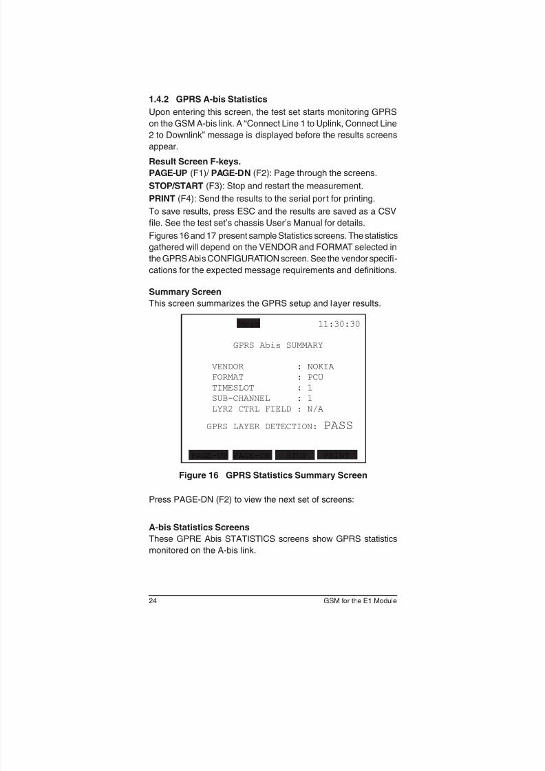
1.4.2 GPRS A-bis Statistics
Upon entering this screen, the test set starts monitoring GPRS
on the GSM A-bis link. A “Connect Line 1 to Uplink, Connect Line
2 to Downlink” message is displayed before the results screens
appear.
Result Screen F-keys.
PAGE-UP (F1)/ PAGE-DN (F2): Page through the screens.
STOP/START (F3): Stop and restart the measurement.
PRINT (F4): Send the results to the serial por t for printing.
To save results, press ESC and the results are saved as a CSV
file. See the test set’s chassis User’s Manual for details.
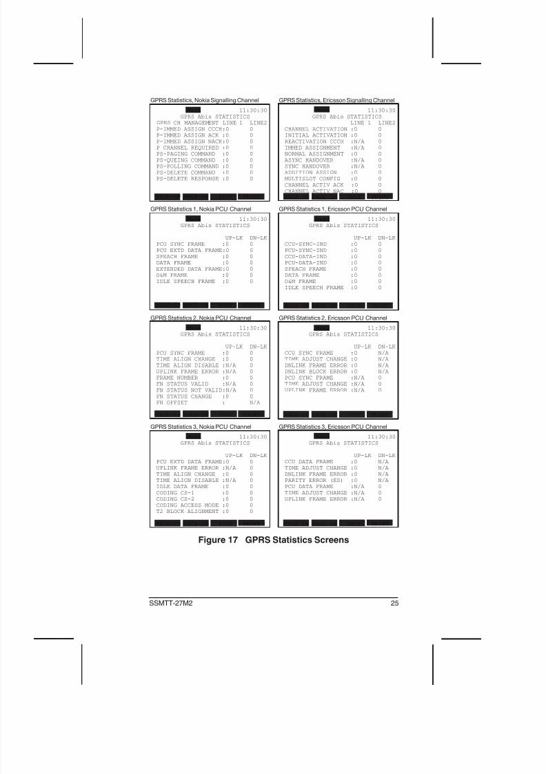
Figures 16 and 17 present sample Statistics screens. The statistics
gathered will depend on the VENDOR and FORMAT selected in
the GPRS Abis CONFIGURATION screen. See the vendor speci-
cations for the expected message requirements and definitions.
Summary Screen
This screen summarizes the GPRS setup and layer results.
Meas 11:30:30
GPRS Abis SUMMARY
VENDOR : NOKIA
FORMAT : PCU
TIMESLOT : 1
SUB-CHANNEL : 1
LYR2 CTRL FIELD : N/A
GPRS LAYER DETECTION: PASS
PAGE-UP PAGE-DN STOP PRINT
Figure 16 GPRS Statistics Summary Screen
Press PAGE-DN (F2) to view the next set of screens:
A-bis Statistics Screens
These GPRE Abis STATISTICS screens show GPRS statistics
monitored on the A-bis link.
25SSMTT-27M2
Meas 11:30:30
GPRS Abis STATISTICS
GPRS CH MANAGEMENT LINE 1 LINE2
P-IMMED ASSIGN CCCH:0 0
P-IMMED ASSIGN ACK :0 0
P-IMMED ASSIGN NACK:0 0
P CHANNEL REQUIRED :0 0
PS-PAGING COMMAND :0 0
PS-QUEING COMMAND :0 0
PS-POLLING COMMAND :0 0
PS-DELETE COMMAND :0 0
PS-DELETE RESPONSE :0 0
PAGE-UP PAGE-DN STOP PRINT
GPRS Statistics, Nokia Signalling Channel
Meas 11:30:30
GPRS Abis STATISTICS
LINE 1 LINE2
CHANNEL ACTIVATION :0 0
INITIAL ACTIVATION :0 0
REACTIVATION CCCH :N/A 0
IMMED ASSIGNMENT :N/A 0
NORMAL ASSIGNMENT :0 0
ASYNC HANDOVER :N/A 0
SYNC HANDOVER :N/A 0
ADDITION ASSIGN :0 0
MULTISLOT CONFIG :0 0
CHANNEL ACTIV ACK :0 0
CHANNEL ACTIV NAC :0 0
PAGE-UP PAGE-DN STOP PRINT
GPRS Statistics, Ericsson Signalling Channel
Meas 11:30:30
GPRS Abis STATISTICS
UP-LK DN-LK
PCU SYNC FRAME :0 0
PCU EXTD DATA FRAME:0 0
SPEACH FRAME :0 0
DATA FRAME :0 0
EXTENDED DATA FRAME:0 0
O&M FRAME :0 0
IDLE SPEECH FRAME :0 0
PAGE-UP PAGE-DN STOP PRINT
GPRS Statistics 1, Nokia PCU Channel
Meas 11:30:30
GPRS Abis STATISTICS
UP-LK DN-LK
CCU-SYNC-IND :0 0
PCU-SYNC-IND :0 0
CCU-DATA-IND :0 0
PCU-DATA-IND :0 0
SPEACH FRAME :0 0
DATA FRAME :0 0
O&M FRAME :0 0
IDLE SPEECH FRAME :0 0
PAGE-UP PAGE-DN STOP PRINT
GPRS Statistics 1, Ericsson PCU Channel
Meas 11:30:30
GPRS Abis STATISTICS
UP-LK DN-LK
PCU SYNC FRAME :0 0
TIME ALIGN CHANGE :0 0
TIME ALIGN DISABLE :N/A 0
UPLINK FRAME ERROR :N/A 0
FRAME NUMBER :0 0
FN STATUS VALID :N/A 0
FN STATUS NOT VALID:N/A 0
FN STATUS CHANGE :0 0
FN OFFSET : N/A
PAGE-UP PAGE-DN STOP PRINT
GPRS Statistics 2, Nokia PCU Channel
Meas 11:30:30
GPRS Abis STATISTICS
UP-LK DN-LK
CCU SYNC FRAME :0 N/A
TIME ADJUST CHANGE :0 N/A
DNLINK FRAME ERROR :0 N/A
DNLINK BLOCK ERROR :0 N/A
PCU SYNC FRAME :N/A 0
TIME ADJUST CHANGE :N/A 0
UPLINK FRAME ERROR :N/A 0
PAGE-UP PAGE-DN STOP PRINT
GPRS Statistics 2, Ericsson PCU Channel
Meas 11:30:30
GPRS Abis STATISTICS
UP-LK DN-LK
PCU EXTD DATA FRAME:0 0
UPLINK FRAME ERROR :N/A 0
TIME ALIGN CHANGE :0 0
TIME ALIGN DISABLE :N/A 0
IDLE DATA FRAME :0 0
CODING CS-1 :0 0
CODING CS-2 :0 0
CODING ACCESS MODE :0 0
T2 BLOCK ALIGNMENT :0 0
PAGE-UP PAGE-DN STOP PRINT
GPRS Statistics 3, Nokia PCU Channel
Meas 11:30:30
GPRS Abis STATISTICS
UP-LK DN-LK
CCU DATA FRAME :0 N/A
TIME ADJUST CHANGE :0 N/A
DNLINK FRAME ERROR :0 N/A
PARITY ERROR (ES) :0 N/A
PCU DATA FRAME :N/A 0
TIME ADJUST CHANGE :N/A 0
UPLINK FRAME ERROR :N/A 0
PAGE-UP PAGE-DN STOP PRINT
GPRS Statistics 3, Ericsson PCU Channel
Figure 17 GPRS Statistics Screens
26 GSM for the E1 Module
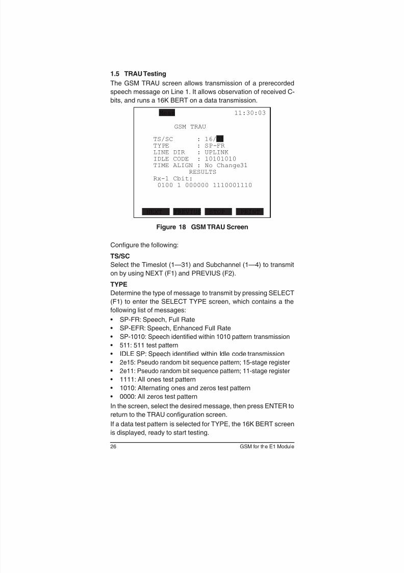
1.5 TRAU Testing
The GSM TRAU screen allows transmission of a prerecorded
speech message on Line 1. It allows observation of received C-
bits, and runs a 16K BERT on a data transmission.
Figure 18 GSM TRAU Screen
Congure the following:
TS/SC
Select the Timeslot (1—31) and Subchannel (1—4) to transmit
on by using NEXT (F1) and PREVIUS (F2).
TYPE
Determine the type of message to transmit by pressing SELECT
(F1) to enter the SELECT TYPE screen, which contains a the
following list of messages:
• SP-FR: Speech, Full Rate
• SP-EFR: Speech, Enhanced Full Rate
• SP-1010: Speech identied within 1010 pattern transmission
• 511: 511 test pattern
• IDLE SP: Speech identied within Idle code transmission
• 2e15: Pseudo random bit sequence pattern; 15-stage register
• 2e11: Pseudo random bit sequence pattern; 11-stage register
• 1111: All ones test pattern
• 1010: Alternating ones and zeros test pattern
• 0000: All zeros test pattern
In the screen, select the desired message, then press ENTER to
return to the TRAU configuration screen.
If a data test pattern is selected for TYPE, the 16K BERT screen
is displayed, ready to start testing.
27SSMTT-27M2
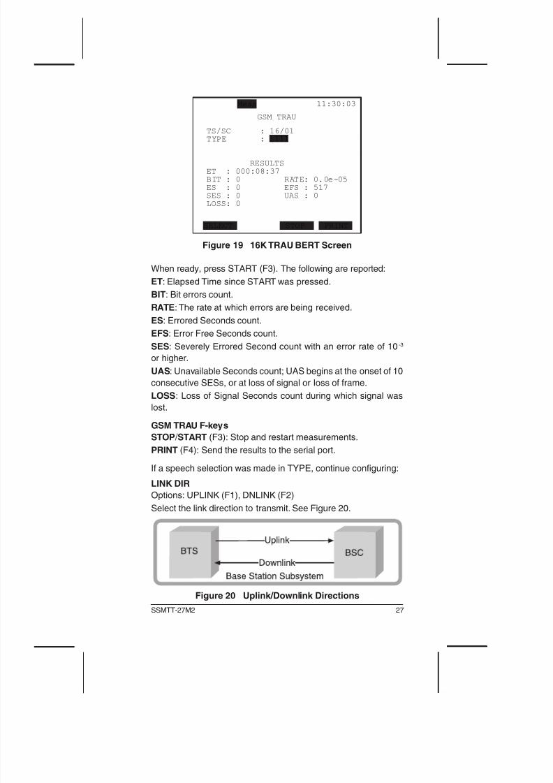
Figure 19 16K TRAU BERT Screen
When ready, press START (F3). The following are reported:
ET: Elapsed Time since START was pressed.
BIT: Bit errors count.
RATE: The rate at which errors are being received.
ES: Errored Seconds count.
EFS: Error Free Seconds count.
SES: Severely Errored Second count with an error rate of 10 -3
or higher.
UAS: Unavailable Seconds count; UAS begins at the onset of 10
consecutive SESs, or at loss of signal or loss of frame.
LOSS: Loss of Signal Seconds count during which signal was
lost.
GSM TRAU F-keys
STOP / START (F3): Stop and restart measurements.
PRINT (F4): Send the results to the serial port.
If a speech selection was made in TYPE, continue conguring:
LINK DIR
Options: UPLINK (F1), DNLINK (F2)
Select the link direction to transmit. See Figure 20.
Figure 20 Uplink/Downlink Directions
28 GSM for the E1 Module
IDLE CODE
Set the idle code inserted on the non-selected channels by press-
ing SHIFT and using the numeric keys to enter the digits. Use the
arrow keys to move between digits as required.
TIME ALIGN
The default is no delay, “No Change” to the voice signal.
Change the delay time by pressing INC+1 (F1) DEC-1 (F2) or
to change the delay by steps of 500 ms. Press INC+10 (F3) to
increment delay by steps of 10 x 500 ms.
When ready, press START and observe the results:
RESULTS
Observe the received C-bits at the Rx-1 line.
29SSMTT-27M2
2 Applications
2.1 A-bis Monitoring
Monitor both directions of A-bis signalling to get a complete picture
of the state of the line.
1. From the module’s main menu, select TEST CONFIGURATION
and congure as follows: TEST MODE: E1DUAL
Tx/INSERT: L1-TX RX/DROP: L1-RX
TxSOURCE: TESTPAT FRAMING: PCM-31 CRC-4: as required
TEST RATE: 2.048M L1-Rx Port: BRIDGE
L2-Rx Port: BRIDGE
TX CLOCK: RECEIVE
LED SOURCE: as required.
When nished, press ENTER.
2. Select from the module main menu, PROTOCOLS > GSM
ANALYSIS > PROTOCOL ANALYSIS > CONFIGURATION
and congure as follows:
RATE: 64K CRC-4: OFF SIGNALLING T/S: 16
SUB-CHANNEL: N/A L1-Rx: BRIDGE
L2-Rx: BRIDGE
SAPI/TEI FORMAT: DECIMAL
LYR CTRL FIELD: MOD128
When nished, press ENTER.
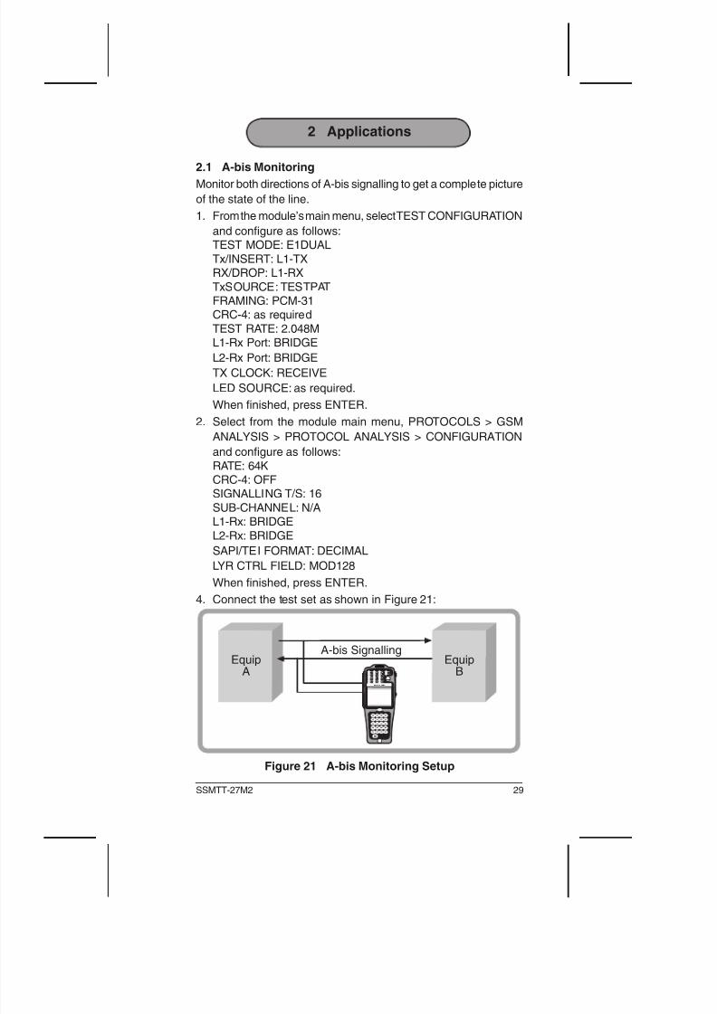
4. Connect the test set as shown in Figure 21:
Figure 21 A-bis Monitoring Setup
30 GSM for the E1 Module
5. Press HISTORY to turn off any blinking LEDs.
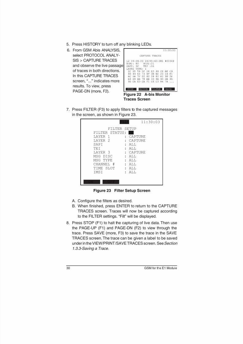
6. From GSM Abis ANALYSIS,
select PROTOCOL ANALY-
SIS > CAPTURE TRACES
and observe the live passage
of traces in both directions.
In this CAPTURE TRACES
screen, “...” indicates more
results. To view, press
PAGE-DN (more, F2).Figure 22 A-bis MonitorTraces Screen
7. Press FILTER (F3) to apply lters to the captured messages
in the screen, as shown in Figure 23.
Figure 23 Filter Setup Screen
A. Configure the filters as desired.
B. When nished, press ENTER to return to the CAPTURE
TRACES screen. Traces will now be captured according
to the FILTER settings. “Filt” will be displayed.
8. Press STOP (F1) to halt the capturing of live data. Then use
the PAGE-UP (F1) and PAGE-DN (F2) to view through the
trace. Press SAVE (more, F3) to save the trace in the SAVE
TRACES screen. The trace can be given a label to be saved
under in the VIEW/PRINT/SAVE TRACES screen. SeeSection
1.3.3-Saving a Trace .
31SSMTT-27M2
3 Reference
3.1 GSM Technology Overview
GSM, Global System for Mobile communication, is governed by
ETSI transmission standards. GSM technology uses a digital
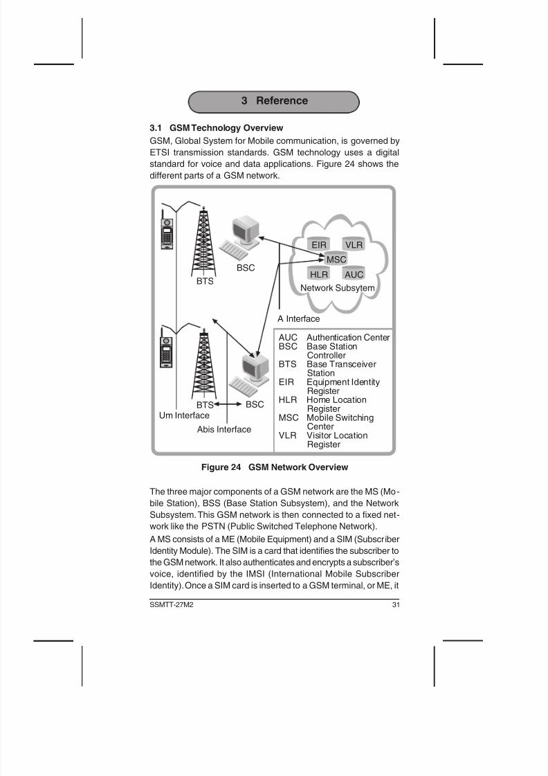
standard for voice and data applications. Figure 24 shows the
different parts of a GSM network.
Figure 24 GSM Network Overview
The three major components of a GSM network are the MS (Mo -
bile Station), BSS (Base Station Subsystem), and the Network
Subsystem. This GSM network is then connected to a xed net-
work like the PSTN (Public Switched Telephone Network).
A MS consists of a ME (Mobile Equipment) and a SIM (Subscriber
Identity Module). The SIM is a card that identies the subscriber to
the GSM network. It also authenticates and encrypts a subscriber’s
voice, identied by the IMSI (International Mobile Subscriber
Identity). Once a SIM card is inserted to a GSM terminal, or ME, it
32 GSM for the E1 Module
becomes a MS. Like the SIM, the ME can also be identied using
the IMEI (International Mobile Equipment Identity).
While a subscriber roams or is stationary, the MS transmits a radio
signal to one of the many BTS (Base Transceiver Station). These
rugged, compact BTS cells are equipped with radio transceivers
to send and receive signals using a radio-link protocol via a Um
interface.
The BTSs are in turn managed by a BSC (Base Station Controller).
Using the A-bis interface, the BSC handles radio-channel setup,
frequency hopping for security measures, and handovers. In some
instances a TRAU (Transcoder Rate Adaption Unit) is placed at a
BTS to perform transcoding between 64 kbit/s A-law speech and
13 kbit/s RPELTP speech. The TRAU may also be located at or in
conjunction with the BSC. The BSC then connects the MS to the
MSC (Mobile Switching Center) using the A-interface.
Using four registers, the MSC handles subscriber registration,
authentication, location updates, handovers, and call roaming.
The HLR (Home Location Register) is the central database for
all subscribers holding identity of the subscriber, services acces-
sible to the subscriber, and current location of the MS. Given a
MSISDN (Mobile Subscriber ISDN) number, a call can be routed
by looking up the corresponding IMSI found in the HLR.
The VLR (Visitor’s Location Register) contains information about
all Mobile Stations within the area served by the MSC. Informa-
tion such as MS identity, the area in which it was last registered,
additional information pertaining to the subscriber, and any
supplementary services available are found in the VLR.
An MSC refers to the VLR each time a MS receives or makes a
call. A security register called the AUC (Authentication Centre)
validates a SIM and performs a mathematical calculation on the
same secret information stored in SIM. Another security register
is the EIR (Equipment Identity Register). Using a list of three
categories, the EIR ensures that all ME’s being used are valid
and authorized to function on the PLMN (Public Land Mobile
Network). Together, the MSC, HLR, VLR, AUC, and EIR make
up the Network Subsystem that connects the GSM network to a
xed network.
33SSMTT-27M2
3.2 GSM Radio Transmission
At the physical layer, MSs and BSSs use a combination of FDMA
(Frequency-Division Multiple Access ) and TDMA (Time-Division
Multiple Access ) to send information. The 890—915 Mhz range is
used for uplink transmission from MS to BSS and the 935—960
Mhz range for downlink from BSS to MS transmission.
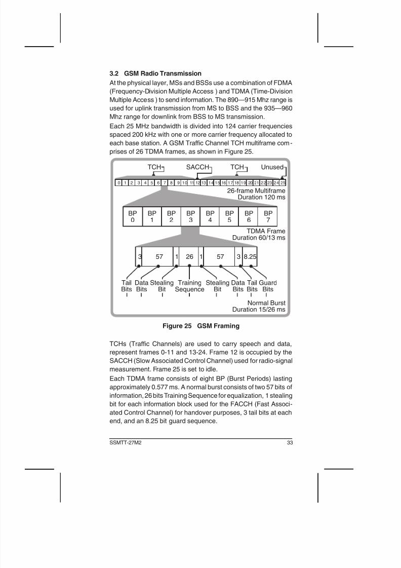
Each 25 MHz bandwidth is divided into 124 carrier frequencies
spaced 200 kHz with one or more carrier frequency allocated to
each base station. A GSM Trafc Channel TCH multiframe com -
prises of 26 TDMA frames, as shown in Figure 25.
Figure 25 GSM Framing
TCHs (Trafc Channels) are used to carry speech and data,
represent frames 0-11 and 13-24. Frame 12 is occupied by the
SACCH (Slow Associated Control Channel) used for radio-signal
measurement. Frame 25 is set to idle.
Each TDMA frame consists of eight BP (Burst Periods) lasting
approximately 0.577 ms. A normal burst consists of two 57 bits of
information, 26 bits Training Sequence for equalization, 1 stealing
bit for each information block used for the FACCH (Fast Associ-
ated Control Channel) for handover purposes, 3 tail bits at each
end, and an 8.25 bit guard sequence.
34 GSM for the E1 Module
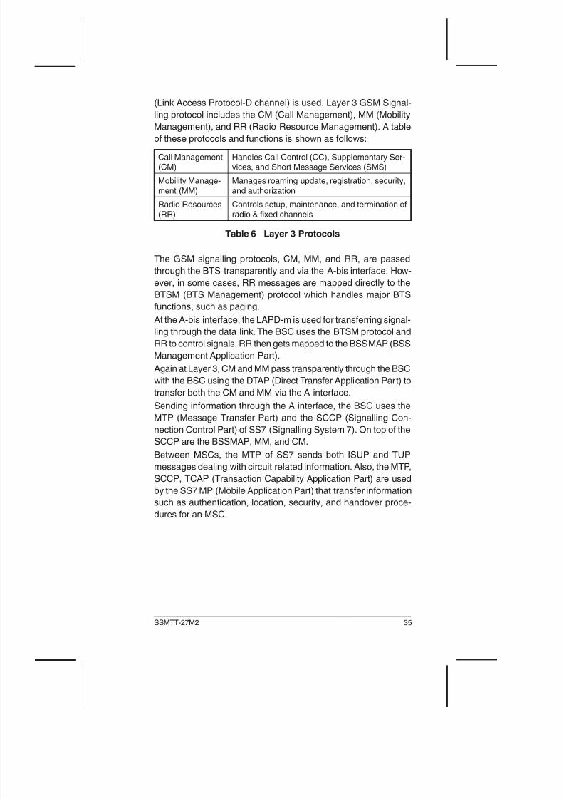
In addition to TCHs, there are CCH (Control Channels) framed in
a 51 TDMA format. The following table lists the different types of
CCH or common control channels and their functions.
Broadcast
Control Channel
(BCCH)
Downlinks information, e.g. base station iden-
tification, frequency allocation and frequency
hopping sequences.
Frequency Cor-
rection Channel(FCCH)
Synchronizes TS structure
Synchronization
Channel (SCH)
Synchronizes TS structure
Random Access
Channel (RACH)
Uplinks requests for access to GSM network
Paging Channel
(PCH)
Downlinks alert signal to MS for use
Access Grant
Channel (AGCH)
Downlinks access to use network using a stand-
alone Dedicated Control Channel (SDCHH)
Table 5 CCH Functions
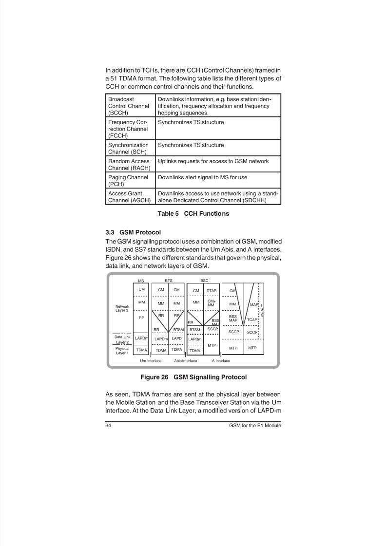
3.3 GSM Protocol
The GSM signalling protocol uses a combination of GSM, modified
ISDN, and SS7 standards between the Um Abis, and A interfaces.
Figure 26 shows the different standards that govern the physical,
data link, and network layers of GSM.
Figure 26 GSM Signalling Protocol
As seen, TDMA frames are sent at the physical layer between
the Mobile Station and the Base Transceiver Station via the Um
interface. At the Data Link Layer, a modied version of LAPD-m
35SSMTT-27M2
(Link Access Protocol-D channel) is used. Layer 3 GSM Signal-
ling protocol includes the CM (Call Management), MM (Mobility
Management), and RR (Radio Resource Management). A table
of these protocols and functions is shown as follows:
Call Management
(CM)
Handles Call Control (CC), Supplementary Ser-
vices, and Short Message Services (SMS)
Mobility Manage-
ment (MM)
Manages roaming update, registration, security,
and authorization
Radio Resources
(RR)
Controls setup, maintenance, and termination of
radio & fixed channels
Table 6 Layer 3 Protocols
The GSM signalling protocols, CM, MM, and RR, are passed
through the BTS transparently and via the A-bis interface. How-
ever, in some cases, RR messages are mapped directly to the
BTSM (BTS Management) protocol which handles major BTS
functions, such as paging.
At the A-bis interface, the LAPD-m is used for transferring signal-
ling through the data link. The BSC uses the BTSM protocol and
RR to control signals. RR then gets mapped to the BSSMAP (BSS
Management Application Part).
Again at Layer 3, CM and MM pass transparently through the BSC
with the BSC using the DTAP (Direct Transfer Application Part) to
transfer both the CM and MM via the A interface.
Sending information through the A interface, the BSC uses the
MTP (Message Transfer Part) and the SCCP (Signalling Con-
nection Control Part) of SS7 (Signalling System 7). On top of the
SCCP are the BSSMAP, MM, and CM.
Between MSCs, the MTP of SS7 sends both ISUP and TUP
messages dealing with circuit related information. Also, the MTP,
SCCP, TCAP (Transaction Capability Application Part) are used
by the SS7 MP (Mobile Application Part) that transfer information
such as authentication, location, security, and handover proce-
dures for an MSC.
36 GSM for the E1 Module
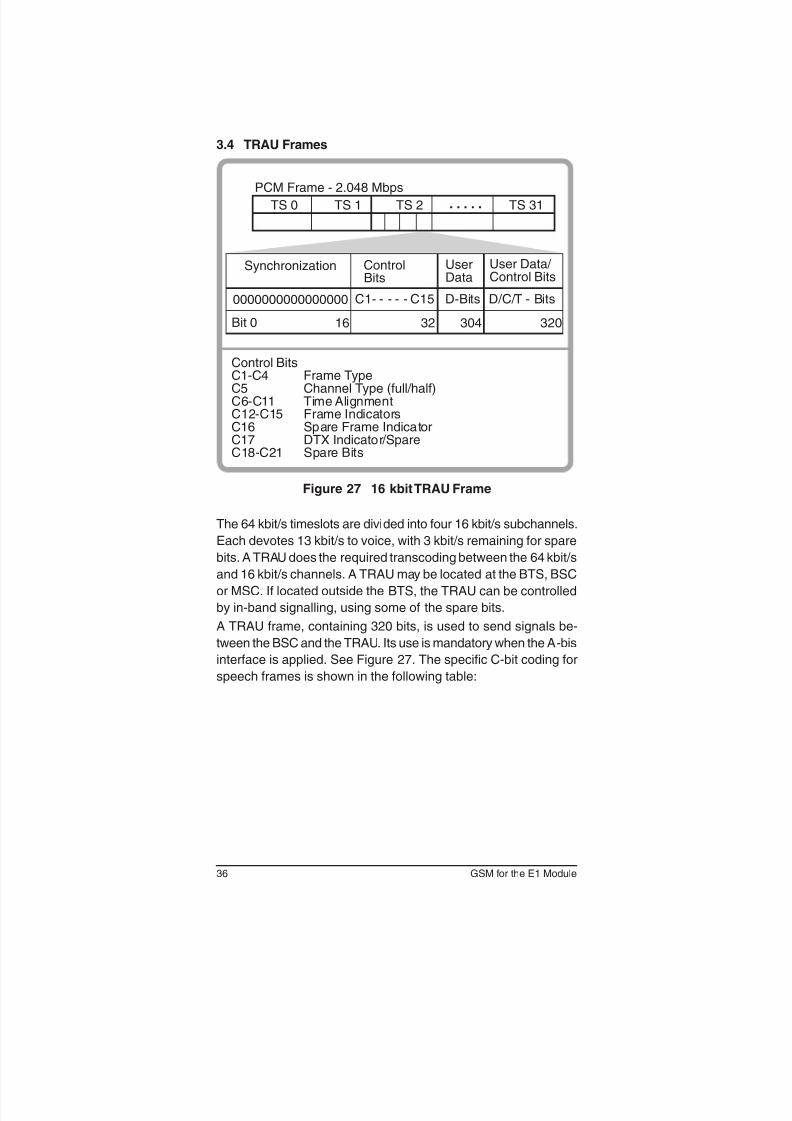
3.4 TRAU Frames
Figure 27 16 kbit TRAU Frame
The 64 kbit/s timeslots are divided into four 16 kbit/s subchannels.
Each devotes 13 kbit/s to voice, with 3 kbit/s remaining for spare
bits. A TRAU does the required transcoding between the 64 kbit/s
and 16 kbit/s channels. A TRAU may be located at the BTS, BSC
or MSC. If located outside the BTS, the TRAU can be controlled
by in-band signalling, using some of the spare bits.
A TRAU frame, containing 320 bits, is used to send signals be-
tween the BSC and the TRAU. Its use is mandatory when the A-bis
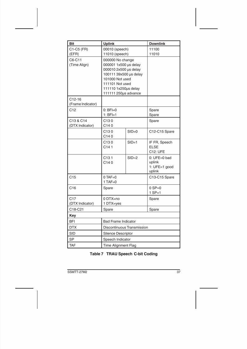
interface is applied. See Figure 27. The specific C-bit coding for
speech frames is shown in the following table:
37SSMTT-27M2
Bit Uplink Downlink
C1-C5 (FR)
(EFR)
00010 (speech)
11010 (speech)
11100
11010
C6-C11
(Time Align)
000000 No change
000001 1x500 µs delay
000010 2x500 µs delay
100111 39x500 µs delay
101000 Not used
111101 Not used
111110 1x250µs delay
111111 250µs advance
C12-16
(Frame Indicator)
C12 0: BFI=0
1: BFI=1
Spare
Spare
C13 & C14
(DTX Indicator)
C13 0
C14 0
Spare
C13 0
C14 0
SID=0 C12-C15 Spare
C13 0
C14 1
SID=1 IF FR, Speech
ELSE
C12: UFE
C13 1
C14 0
SID=2 0: UFE=0 baduplink
1: UFE=1 gooduplink
C15 0 TAF=0
1 TAF=0
C13-C15 Spare
C16 Spare 0 SP=0
1 SP=1
C17
(DTX Indicator)
0 DTX=no
1 DTX=yes
Spare
C18-C21 Spare Spare
Key
BFI Bad Frame Indicator
DTX Discontinuous Transmission
SID Silence Descriptor
SP Speech Indicator
TAF Time Alignment Flag
Table 7 TRAU Speech C-bit Coding
38 GSM for the E1 Module
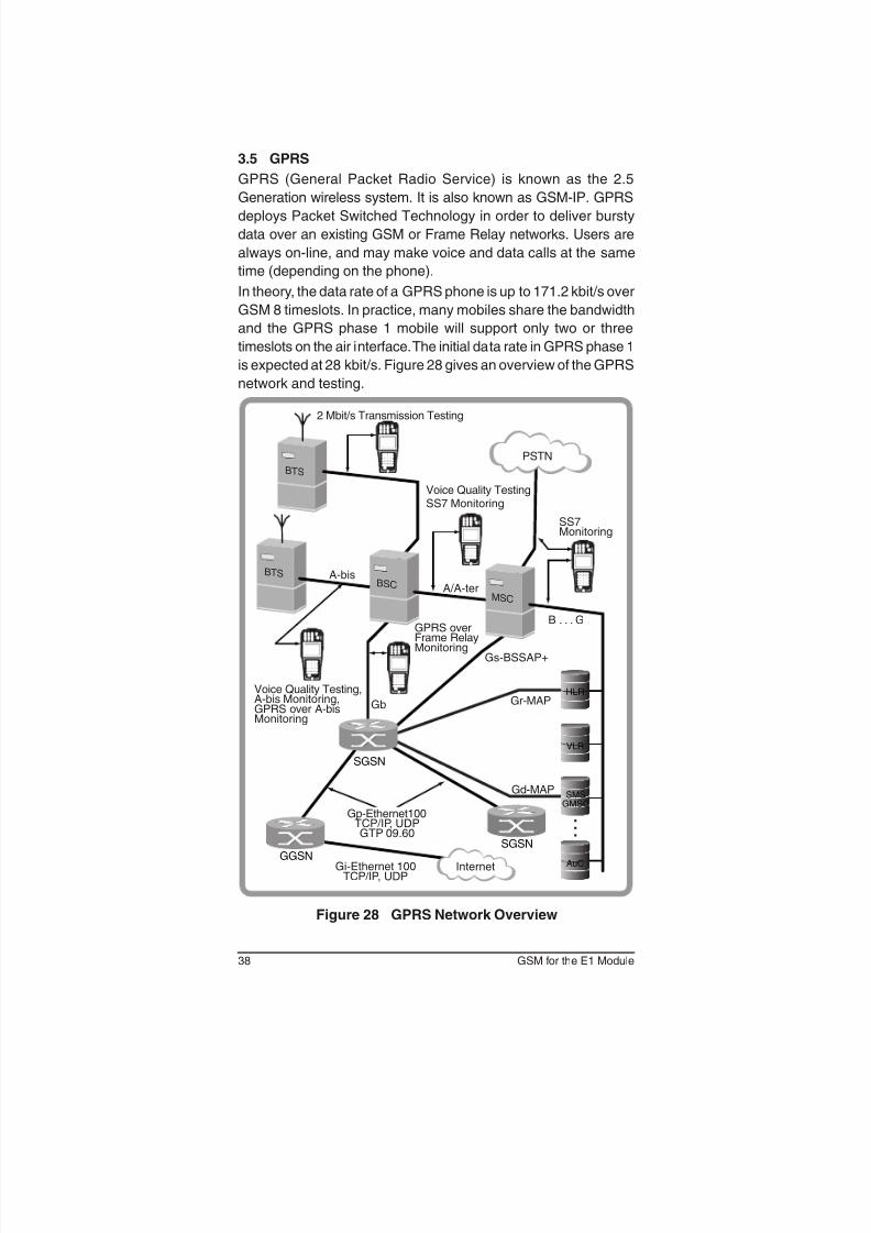
3.5 GPRS
GPRS (General Packet Radio Service) is known as the 2.5
Generation wireless system. It is also known as GSM-IP. GPRS
deploys Packet Switched Technology in order to deliver bursty
data over an existing GSM or Frame Relay networks. Users are
always on-line, and may make voice and data calls at the same
time (depending on the phone).
In theory, the data rate of a GPRS phone is up to 171.2 kbit/s over
GSM 8 timeslots. In practice, many mobiles share the bandwidth
and the GPRS phase 1 mobile will support only two or three
timeslots on the air interface. The initial data rate in GPRS phase 1
is expected at 28 kbit/s. Figure 28 gives an overview of the GPRS
network and testing.
BTS
Voice Quality Testing,A-bis Monitoring,GPRS over A-bisMonitoring
GPRS overFrame RelayMonitoring
Voice Quality TestingSS7 Monitoring
SS7Monitoring
2 Mbit/s Transmission Testing
A-bisA/A-ter
BTS
Internet
PSTN
Gs-BSSAP+
Gi-Ethernet 100TCP/IP, UDP
GGSNSGSN
B . . . G
Gr-MAP
Gd-MAP
. . .
VLR
AuC
HLR
SMSGMSC
BSC
MSC
SGSN
Gb
Gp-Ethernet100TCP/IP, UDPGTP 09.60
Figure 28 GPRS Network Overview
39SSMTT-27M2
There are two main GPRS elements over the GSM network,
SGSN and GGSN.
Servicing GPRS Support Node (SGSN)
SGSN controls all aspects of connection between the network
and Mobile Station by providing:
• Session Management
• Authentication and Mobility Management: handover
• Connect to VLR (Visitor’s Location Register ) using Gs based
on BSSAP+ (Base Station Subsystem Application Part)
Gateway GPRS Support Node (GGSN)
GGSN provides the following functions:
• Counts the number of packets for billing purposes.
• Gateway to PDN (Public Data Network): authentication and
location management function
• Firewall
Packet Control Unit (PCU)
The PCU is located at the Base Station Controller (BSC) to convert
packet data into a radio format that can be transmitted.
• Radio Resource Management
• Quality of Service (throughput, delay, reliability, priority)
Packet Data Protocol (PDP)
PDP opens a session for a mobile to request a temporary IP ad-
dress (supporting IPv4 32-bit addressing).
GPRS Gb Protocol Stack
Layer 1: Frame Relay Forum FRF 1.1
Layer 2: Network Service
Layer 3: BSSGP (Base Station System GPRS Protocol)
Layer 4, 5: LLC (Logical Link Control)
Layer 7: SNDCP (Subnetwork Dependent Convergence Proto-
col)

40 GSM for the E1 Module
41SSMTT-27M2
4 General Information
4.1 Testing and Calibration Statement
Sunrise Telecom certies that this product was manufactured,
tested, and verified according to the applicable Sunrise Telecom
Incorporated manufacturing and test procedure(s). These formal
procedures are designed to assure that the product meets its
required specifications.
This product has no user-adjustable settings. During normal usage,
periodic calibration is not a requirement. However, if the product
fails during the self-verication test, during power up, the product
can be returned to the manufacturer for evaluation and repair.
4.2 Offices
Sunrise Telecom ofces are located around the world:
• SUNRISE TELECOM INCORPORATED
302 Enzo Drive San Jose, CA 95138 U.S.A.
Tel: 1-800-701-5208 Fax: 1-408-363-8313
Internet: http://www.sunrisetelecom.com
E-mail: [email protected]
• SUNRISE TELECOM ATLANTA
3075 Northwoods Circle, Norcross, GA 30071, USA
Tel: 770-446-6086, Fax: 770-446-6850
• SUNRISE TELECOM CHINA
Room 1503, Tower 3 , No.1, Xizhimenwai Street
Xicheng District, Beijing, 100044, CHINA
Tel: +86-10-5830-2220, Fax: +86-10-5830-2239
• SUNRISE TELECOM FRANCE SAS
ZA Courtaboeuf 2 - Immeuble le Ceylan
6 Allée de Londres 91140 Villejust, FRANCE
Tel: +33 (0) 1 6993 8990, Fax: +33 (0) 1 6993 8991
• SUNRISE TELECOM GERMANY
Grabenstrasse 1, 72116 Mössingen GERMANY
Tel: +49 7473 378 2400 Fax: +49 (0) 7473 378 2424
42 GSM for the E1 Module
• SUNRISE TELECOM TAIWAN
21, Wu Chuan 3rd Road, Wu-Ku Hsiang
Taipei County, 248, Taiwan, R.O.C.
Tel: +886-2-5578-0788, Fax: +886-2-2298-2575
43SSMTT-27M2
4.3 Express Limited Warranty
This Sunrise Telecom product is warranted against defects in
materials and workmanship during its warranty period. The war-
ranty period for this product is contained in the warranty page on
http://www.sunrisetelecom.com.
Sunrise Telecom agrees to repair or replace any assembly or
component found to be defective under normal use during this
period. The obligation under this warranty is limited solely to re-
pairing or replacing the product that proves to be defective within
the scope of the warranty when returned to the factory. This war -
ranty does not apply under certain conditions, as set forth on the
warranty page on http://www.sunrisetelecom.com.
Please refer to the website for specic details.
THIS IS A LIMITED WARRANTY AND THE ONLY WARRANTY
MADE BY SUNRISE TELECOM. SUNRISE TELECOM MAKES
NO OTHER WARRANTY, REPR SENTATION OR CONDITION,
EXPRESS OR IMPLIED, AND EXPRESSLY DISCLAIMS THE
IMPLIED WARRANTIES OF MERCHANTABILITY, FITNESS
FOR A PARTICULAR PURPOSE AND NON-INFRINGEMENT
OF THIRD PARTY RIGHTS..

44 GSM for the E1 Module
45SSMTT-27M2
Index
Symbols
16 kbit TRAU Frame; 3616K TRAU BERT Screen
BIT; 27EFS; 27
ES; 27ET; 27LOSS; 27
RATE; 27SES; 27
UAS; 27
A
A-bis Capture Traces Screen; 17A-bis Filter Setup Screen
CHANNEL #; 16FILTER STATUS; 12IMSI; 17
LAYER 1; 12LAYER 2; 12
LAYER 3; 13MSG DISC; 13
MSG TYPE; 13SAPI; 12
TEI; 13TIMESLOT; 17
Abis/A-ter GSM Monitor Screens
-; 7A; 7
Abis; 7D; 7
Extended Data; 7FASW; 7I; 7
M; 7P; 7
S; 7A GSM Monitor Screens; 9
A GSM Voice Decoding Screens; 9Applications
A-bis Monitoring; 29
46 GSM for the E1 Module
CCautions; 2
CCH Functions; 34Common Channel Message Types; 14
DDedicated Channel Message Types; 16
FFigures
01 GSM Analysis Menu; 502 Abis/A-ter GSM Monitor Screens; 6
03 Abis/A-ter GSM Voice Decoding Screens; 704 A GSM Monitor Screens; 905 A GSM Voice Decoding Screens; 9
06 GSM Abis Conguration Screen; 1007 A-bis Filter Setup Screen; 12
08 A-bis Capture Traces Screen; 1709 View/Print/Save Traces Screen; 18
10 View Screen; 1811 View Trace Sample Screens; 1912 Print Test Screen; 20
13 Save Traces Screen; 2014 Edit Traces Screen; 21
15 GPRS A-bis Conguration Screen; 2216 GPRS Statistics Summary Screen; 24
17 GPRS Statistics Screens; 2518 GSM TRAU Screen; 2619 16K TRAU BERT Screen; 27
20 Uplink/Downlink Directions; 2721 A-bis Monitoring Setup; 29
22 Sample A-bis Monitor Traces Screen; 3023 Filter Setup Screen; 30
24 GSM Network Overview; 3125 GSM Framing; 3326 GSM Signalling Protocol; 34
27 16 kbit TRAU Frame; 3628 GPRS Network Overview; 38
GGPRS A-bis Configuration Screen
FORMATSIGNAL or PCU; 22
LYR2 CTRL FIELDMOD8 or MOD128; 23
SIGNALLING T/S; 23
47SSMTT-27M2
SUB-CHANNEL; 23
VENDOR; 22GPRS Network Overview; 38GPRS Statistics Screens; 25
GPRS Statistics Summary Screen; 24GRPS Abis Statistics
Abis Statistics Screens; 25Summary Screen; 24
GSM Abis Configuration ScreenCRC-4; 10L1-RX/L2-RX
TERM, BRIDGE, or MONITOR; 10LYR2 CTRL FIELD
MOD8 or MOD128; 11RATE; 10
SAPI /TEI FORMAT; 11SIGNALLING T/S; 10
SUBCHANNEL; 10GSM Framing; 33GSM Network Overview; 31
GSM Signalling Protocol; 34
L
Layer 3 Protocols; 35
O
Ofces; 41
R
Radio Link Layer Message Types; 14
T
Tables01 Radio Link Layer Message Types; 14
02 Common Channel Message Types; 1403 TRX Message Types; 1504 Dedicated Channel Message Types; 16
05 CCH Functions; 3406 Layer 3 Protocols; 35
07 TRAU Speech C-bit Coding; 37TDMA; 33
TRAU ScreenIDLE CODE; 28LINK DIR; 27
TIME ALIGN; 28TS/SC; 26
48 GSM for the E1 Module
TRAU Speech C-bit Coding; 37
TRAU TestingTYPE
SP-FR, SP-EFR, SP-1010, 411, IDLE SP, 2e15, 2e11,
1111, 1010, or 0000; 26TRX Message Types; 15
VView/Print/Save Traces
Deleting a Trace; 20Editing a Trace; 21
Printing a Saved Trace; 20Saving a Trace; 20Viewing a Saved Trace; 18
Voice Decoding Screens#BFI; 8
#DTX; 8C1—C21; 8
LINE 1/2 T/S; 8LVL; 8S/C; 8
TIME ALIGNT; 8UFE; 8
UP/DOWNLINK; 8
W
Warnings; 2Warranty; 43