Embed Size (px)
Citation preview

evoflat.danfoss.com
MAKING MODERN LIVING POSSIBLE
DESIGN GUIDE – The Danfoss EvoFlat system from A-Z
Take lead on your projectwith an efficient system concept
30%By increasing awareness about actual heat usage, individual metering in each apartment reduces energy consumption by as much as 30%.
lower energy consumption
SafeEvoFlat systems provide heating and domestic hot water rapidly on demand while significantly reducing the risk of bacteria in the water.
and comfortable
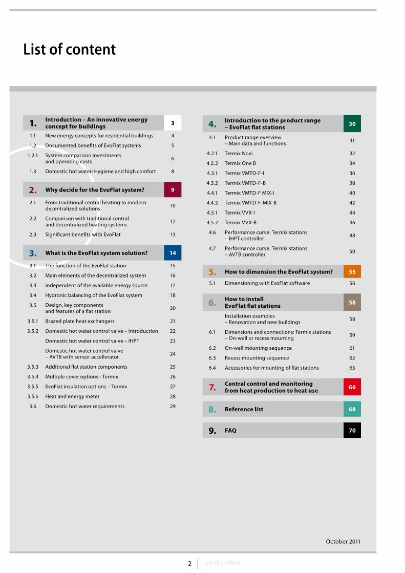
2 List of content
List of content
October 2011
1. Introduction – An innovative energy concept for buildings 3
1.1 New energy concepts for residential buildings 4
1.2 Documented benefits of EvoFlat systems 5
1.2.1 System comparison investmentsand operating costs 6
1.3 Domestic hot water: Hygiene and high comfort 8
2. Why decide for the EvoFlat system? 9
2.1 From traditional central heating to modern decentralized solutions 10
2.2 Comparison with traditional centraland decentralized heating systems 12
2.3 Significant benefits with EvoFlat 13
3. What is the EvoFlat system solution? 14
3.1 The function of the EvoFlat station 15
3.2 Main elements of the decentralized system 16
3.3 Independent of the available energy source 17
3.4 Hydronic balancing of the EvoFlat system 18
3.5 Design, key componentsand features of a flat station 20
3.5.1 Brazed plate heat exchangers 21
3.5.2 Domestic hot water control valve – Introduction 22
Domestic hot water control valve – IHPT 23
Domestic hot water control valve– AVTB with sensor accellerator 24
3.5.3 Additional flat station components 25
3.5.4 Multiple cover options - Termix 26
3.5.5 EvoFlat insulation options – Termix 27
3.5.6 Heat and energy meter 28
3.6 Domestic hot water requirements 29
4. Introduction to the product range – EvoFlat flat stations 30
4.1 Product range overview– Main data and functions 31
4.2.1 Termix Novi 32
4.2.2 Termix One B 34
4.3.1 Termix VMTD-F-I 36
4.3.2 Termix VMTD-F-B 38
4.4.1 Termix VMTD-F MIX-I 40
4.4.2 Termix VMTD-F-MIX-B 42
4.5.1 Termix VVX-I 44
4.5.2 Termix VVX-B 46
4.6 Performance curve: Termix stations– IHPT controller 48
4.7 Performance curve: Termix stations– AVTB controller 50
5. How to dimension the EvoFlat system? 55
5.1 Dimensioning with EvoFlat software 56
6. How to install EvoFlat flat stations 58
Installation examples – Renovation and new buildings 58
6.1 Dimensions and connections: Termix stations– On-wall or recess mounting 59
6.2 On-wall mounting sequence 61
6.3 Recess mounting sequence 62
6.4 Accessories for mounting of flat stations 63
7. Central control and monitoringfrom heat production to heat use 66
8. Reference list 68
9. FAQ 70
3 Introduction
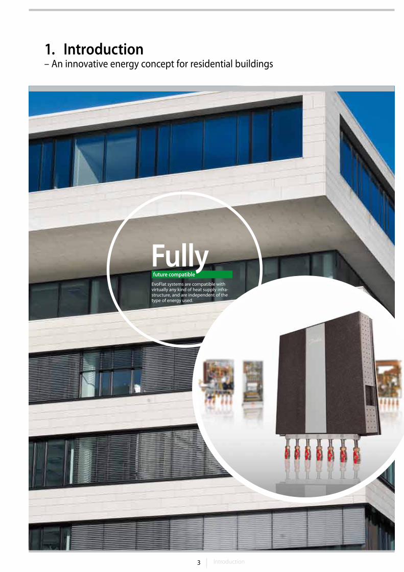
1. Introduction – An innovative energy concept for residential buildings
FullyEvoFlat systems are compatible with virtually any kind of heat supply infra-structure, and are independent of the type of energy used.
future compatible
4 5Introduction
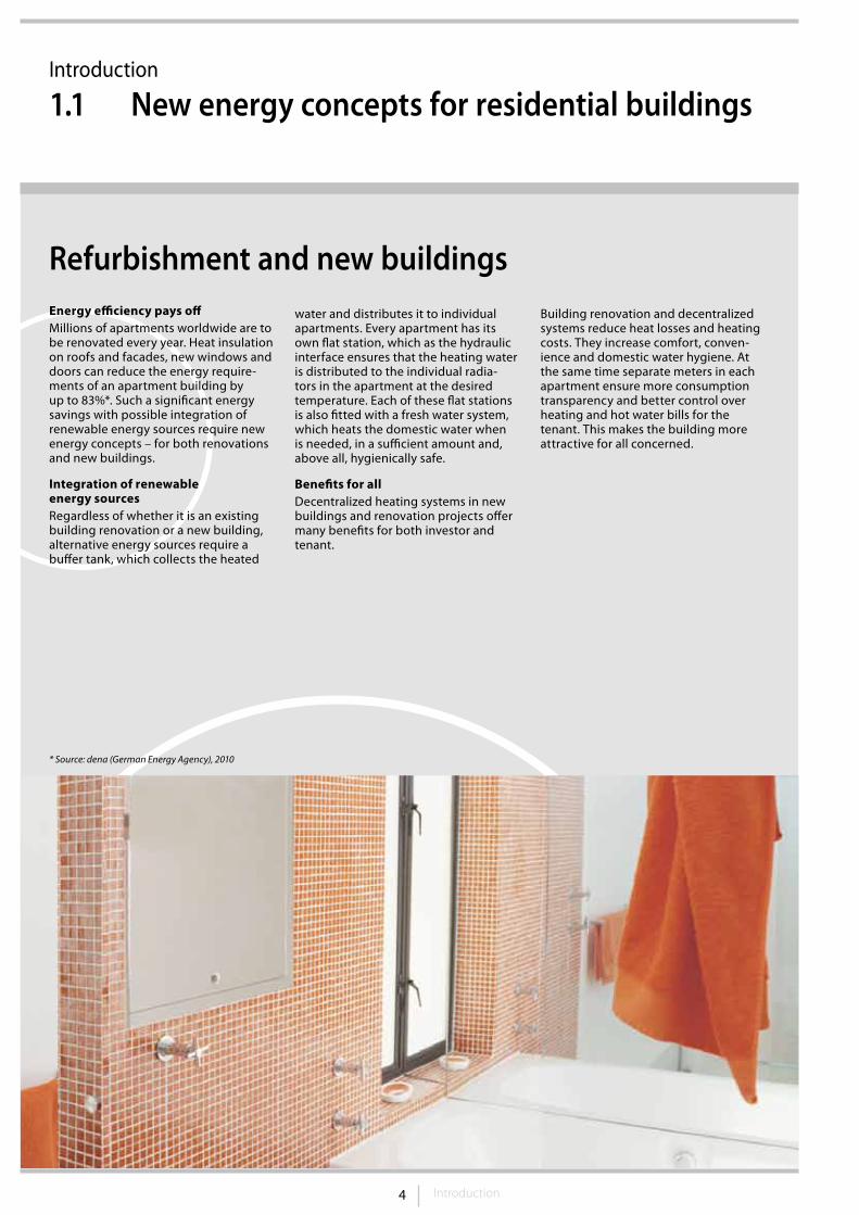
Refurbishment and new buildingsEnergy efficiency pays offMillions of apartments worldwide are to be renovated every year. Heat insulation on roofs and facades, new windows and doors can reduce the energy require-ments of an apartment building by up to 83%*. Such a significant energy savings with possible integration of renewable energy sources require new energy concepts – for both renovations and new buildings.
Integration of renewable energy sourcesRegardless of whether it is an existing building renovation or a new building, alternative energy sources require a buffer tank, which collects the heated
Introduction
1.1 New energy concepts for residential buildings
* Source: dena (German Energy Agency), 2010
water and distributes it to individual apartments. Every apartment has its own flat station, which as the hydraulic interface ensures that the heating water is distributed to the individual radia-tors in the apartment at the desired temperature. Each of these flat stations is also fitted with a fresh water system, which heats the domestic water when is needed, in a sufficient amount and, above all, hygienically safe.
Benefits for allDecentralized heating systems in new buildings and renovation projects offer many benefits for both investor and tenant.
Building renovation and decentralized systems reduce heat losses and heating costs. They increase comfort, conven-ience and domestic water hygiene. At the same time separate meters in each apartment ensure more consumption transparency and better control over heating and hot water bills for the tenant. This makes the building more attractive for all concerned.
5 Introduction
Low overall costs
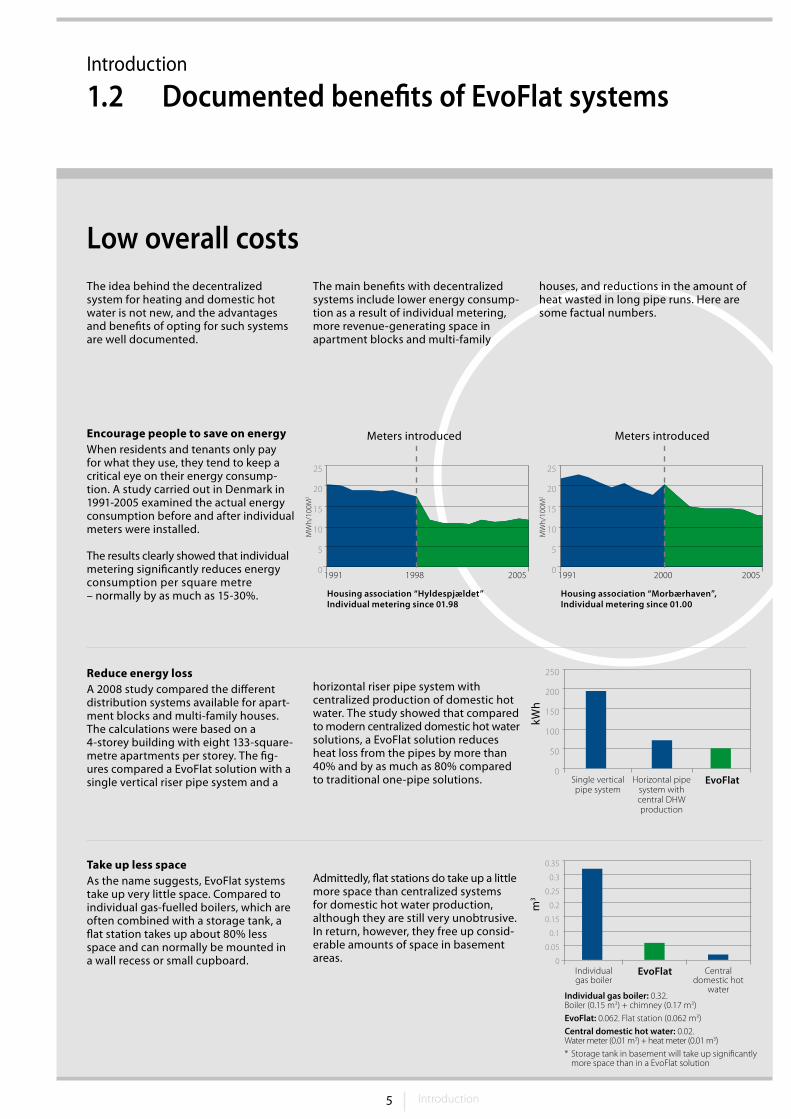
Reduce energy lossA 2008 study compared the different distribution systems available for apart-ment blocks and multi-family houses. The calculations were based on a 4-storey building with eight 133-square-metre apartments per storey. The fig-ures compared a EvoFlat solution with a single vertical riser pipe system and a
horizontal riser pipe system with centralized production of domestic hot water. The study showed that compared to modern centralized domestic hot water solutions, a EvoFlat solution reduces heat loss from the pipes by more than 40% and by as much as 80% compared to traditional one-pipe solutions.
Take up less spaceAs the name suggests, EvoFlat systems take up very little space. Compared to individual gas-fuelled boilers, which are often combined with a storage tank, a flat station takes up about 80% less space and can normally be mounted in a wall recess or small cupboard.
Admittedly, flat stations do take up a little more space than centralized systems for domestic hot water production, although they are still very unobtrusive. In return, however, they free up consid-erable amounts of space in basement areas.
Encourage people to save on energyWhen residents and tenants only pay for what they use, they tend to keep a critical eye on their energy consump-tion. A study carried out in Denmark in 1991-2005 examined the actual energy consumption before and after individual meters were installed.
The results clearly showed that individual metering significantly reduces energy consumption per square metre – normally by as much as 15-30%.
250
200
150
100
50
0Single vertical pipe system
Horizontal pipe system with central DHW production
EvoFlat
Housing association “Hyldespjældet” Individual metering since 01.98
Meters introduced Meters introduced
Housing association “Morbærhaven”, Individual metering since 01.00
The idea behind the decentralized system for heating and domestic hot water is not new, and the advantages and benefits of opting for such systems are well documented.
The main benefits with decentralized systems include lower energy consump-tion as a result of individual metering, more revenue-generating space in apartment blocks and multi-family
houses, and reductions in the amount of heat wasted in long pipe runs. Here are some factual numbers.
MW
h/10
0M2
MW
h/10
0M2
25
20
15
10
5
0
25
20
15
10
5
01991 1998 2005 1991 2000 2005
0.35
0.3
0.25
0.2
0.15
0.1
0.05
0Individual gas boiler
EvoFlat Central domestic hot
waterIndividual gas boiler: 0.32.Boiler (0.15 m3) + chimney (0.17 m3)EvoFlat: 0.062. Flat station (0.062 m3)Central domestic hot water: 0.02. Water meter (0.01 m3) + heat meter (0.01 m3)* Storage tank in basement will take up significantly more space than in a EvoFlat solution
kWh
m3
Introduction
1.2 Documented benefits of EvoFlat systems
6 7Introduction
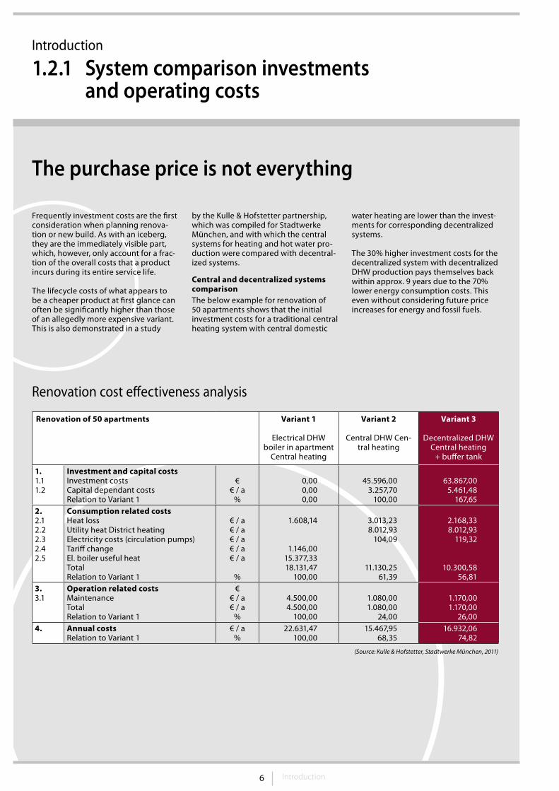
Frequently investment costs are the first consideration when planning renova-tion or new build. As with an iceberg, they are the immediately visible part, which, however, only account for a frac-tion of the overall costs that a product incurs during its entire service life.
The lifecycle costs of what appears to be a cheaper product at first glance can often be significantly higher than those of an allegedly more expensive variant. This is also demonstrated in a study
by the Kulle & Hofstetter partnership, which was compiled for Stadtwerke München, and with which the central systems for heating and hot water pro-duction were compared with decentral-ized systems.
Central and decentralized systems comparisonThe below example for renovation of 50 apartments shows that the initial investment costs for a traditional central heating system with central domestic
water heating are lower than the invest-ments for corresponding decentralized systems.
The 30% higher investment costs for the decentralized system with decentralized DHW production pays themselves back within approx. 9 years due to the 70% lower energy consumption costs. This even without considering future price increases for energy and fossil fuels.
The purchase price is not everything
Renovation cost effectiveness analysis
Renovation of 50 apartments Variant 1
Electrical DHW boiler in apartment
Central heating
Variant 2
Central DHW Cen-tral heating
Variant 3
Decentralized DHW Central heating
+ buffer tank
1.1.11.2
Investment and capital costsInvestment costs Capital dependant costsRelation to Variant 1
€€ / a
%
0,000,000,00
45.596,003.257,70
100,00
63.867,005.461,48
167,652.2.12.22.32.42.5
Consumption related costsHeat lossUtility heat District heatingElectricity costs (circulation pumps)Tariff changeEl. boiler useful heatTotalRelation to Variant 1
€ / a€ / a€ / a€ / a€ / a
%
1.608,14
1.146,0015.377,3318.131,47
100,00
3.013,238.012,93
104,09
11.130,2561,39
2.168,338.012,93
119,32
10.300,5856,81
3.3.1
Operation related costsMaintenanceTotalRelation to Variant 1
€€ / a€ / a
%
4.500,004.500,00
100,00
1.080,001.080,00
24,00
1.170,001.170,00
26,004. Annual costs
Relation to Variant 1€ / a
%22.631,47
100,0015.467,95
68,3516.932,06
74,82
(Source: Kulle & Hofstetter, Stadtwerke München, 2011)
Introduction
1.2.1 System comparison investments and operating costs
7 Introduction
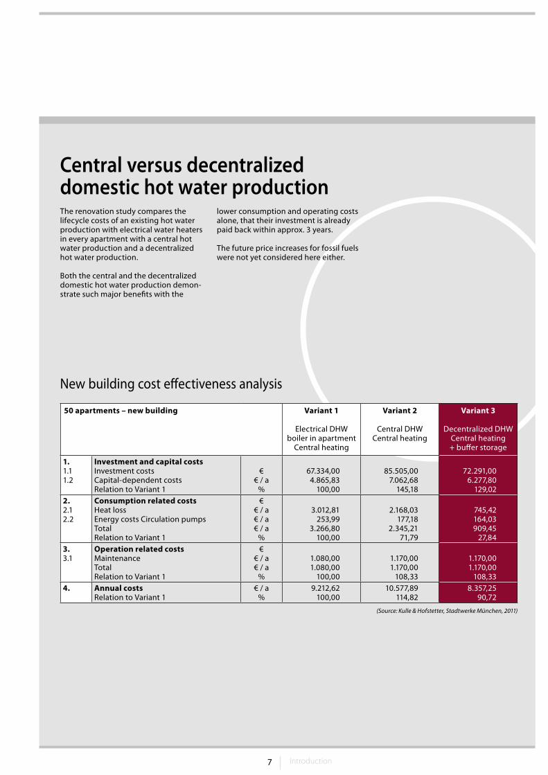
The renovation study compares the lifecycle costs of an existing hot water production with electrical water heaters in every apartment with a central hot water production and a decentralized hot water production.
Both the central and the decentralized domestic hot water production demon-strate such major benefits with the
lower consumption and operating costs alone, that their investment is already paid back within approx. 3 years.
The future price increases for fossil fuels were not yet considered here either.
Central versus decentralized domestic hot water production
New building cost effectiveness analysis
50 apartments – new building Variant 1
Electrical DHW boiler in apartment
Central heating
Variant 2
Central DHW Central heating
Variant 3
Decentralized DHW Central heating + buffer storage
1.1.11.2
Investment and capital costsInvestment costs Capital-dependent costsRelation to Variant 1
€€ / a
%
67.334,004.865,83
100,00
85.505,007.062,68
145,18
72.291,006.277,80
129,022.2.12.2
Consumption related costsHeat loss Energy costs Circulation pumpsTotalRelation to Variant 1
€€ / a€ / a€ / a
%
3.012,81253,99
3.266,80100,00
2.168,03177,18
2.345,2171,79
745,42164,03909,45
27,843.3.1
Operation related costsMaintenanceTotalRelation to Variant 1
€€ / a€ / a
%
1.080,001.080,00
100,00
1.170,001.170,00
108,33
1.170,001.170,00
108,334. Annual costs
Relation to Variant 1€ / a
%9.212,62
100,0010.577,89
114,828.357,25
90,72
(Source: Kulle & Hofstetter, Stadtwerke München, 2011)
8 Introduction
Introduction
1.3 Domestic hot water: hygiene and high comfort
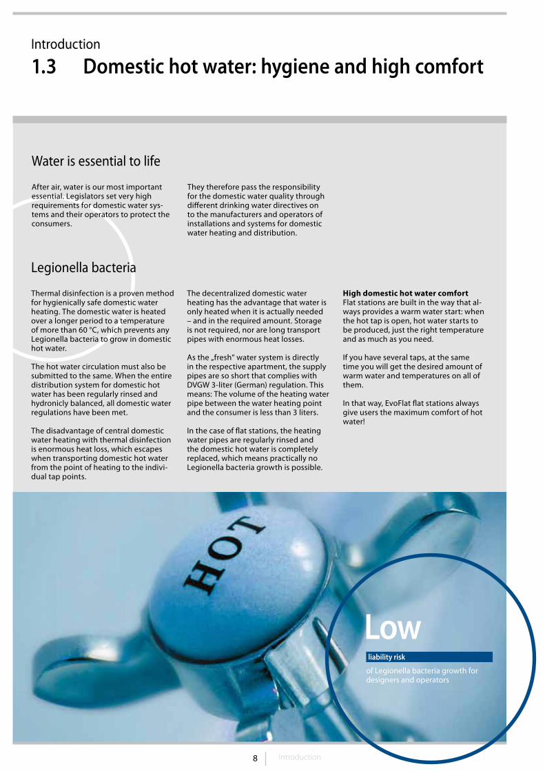
Lowof Legionella bacteria growth for designers and operators
liability risk
Legionella bacteria
Thermal disinfection is a proven method for hygienically safe domestic water heating. The domestic water is heated over a longer period to a temperature of more than 60 °C, which prevents any Legionella bacteria to grow in domestic hot water.
The hot water circulation must also be submitted to the same. When the entire distribution system for domestic hot water has been regularly rinsed and hydronicly balanced, all domestic water regulations have been met.
The disadvantage of central domestic water heating with thermal disinfection is enormous heat loss, which escapes when transporting domestic hot water from the point of heating to the indivi-dual tap points.
The decentralized domestic water heating has the advantage that water is only heated when it is actually needed – and in the required amount. Storage is not required, nor are long transport pipes with enormous heat losses.
As the „fresh“ water system is directly in the respective apartment, the supply pipes are so short that complies with DVGW 3-liter (German) regulation. This means: The volume of the heating water pipe between the water heating point and the consumer is less than 3 liters.
In the case of flat stations, the heating water pipes are regularly rinsed and the domestic hot water is completely replaced, which means practically no Legionella bacteria growth is possible.
High domestic hot water comfortFlat stations are built in the way that al-ways provides a warm water start: when the hot tap is open, hot water starts to be produced, just the right temperature and as much as you need.
If you have several taps, at the same time you will get the desired amount of warm water and temperatures on all of them.
In that way, EvoFlat flat stations always give users the maximum comfort of hot water!
After air, water is our most important essential. Legislators set very high requirements for domestic water sys-tems and their operators to protect the consumers.
They therefore pass the responsibility for the domestic water quality through different drinking water directives on to the manufacturers and operators of installations and systems for domestic water heating and distribution.
Water is essential to life
9 Why decide for the EvoFlat system?
2. Why decide for the EvoFlat system?
10 11Why decide for the EvoFlat system?
Why decide for the EvoFlat system?
2.1 From traditional central heating...
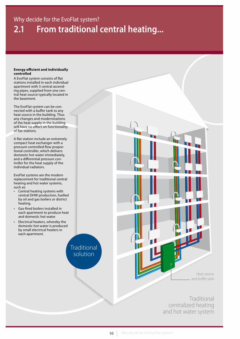
Heat source and buffer tank
Energy efficient and individually controlledA EvoFlat system consists of flat stations installed in each individual apartment with 3 central ascend-ing pipes, supplied from one cen-tral heat source typically located in the basement.
The EvoFlat system can be con-nected with a buffer tank to any heat source in the building. Thus any changes and modernizations of the heat supply in the building will have no effect on functionality of flat stations.
A flat station include an extremely compact heat exchanger with a pressure controlled flow propor-tional controller, which delivers domestic hot water immediately, and a differential pressure con-troller for the heat supply of the individual radiators.
EvoFlat systems are the modern replacement for traditional central heating and hot water systems, such as:• Central heating systems with
central DHW production, fuelled by oil and gas boilers or district heating.
• Gas-fired boilers installed in each apartment to produce heat and domestic hot water.
• Electrical heaters, whereby the domestic hot water is produced by small electrical heaters in each apartment.
Traditional solution
Traditional centralized heating
and hot water system
11 Why decide for the EvoFlat system?
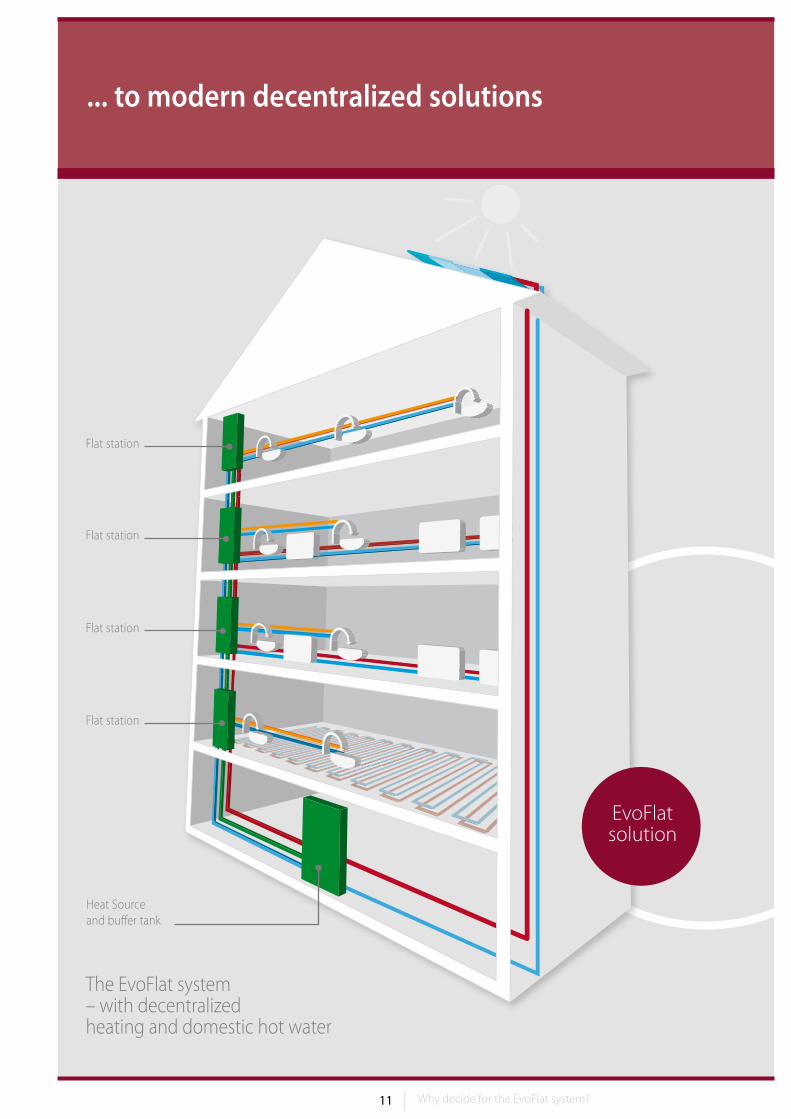
... to modern decentralized solutions
The EvoFlat system – with decentralized heating and domestic hot water
Heat Source and buffer tank
Flat station
Flat station
Flat station
Flat station
EvoFlatsolution
12 13Why decide for the EvoFlat system?
Why decide for the EvoFlat system?
2.2 Comparison with traditional central and decentralized heating systems
ParameterEvoFlat
system with flat stations
Individual gas boiler
Decentralized domestic hot water
Centralized boiler
and domestic hot water
Solar-powered domestic hot water
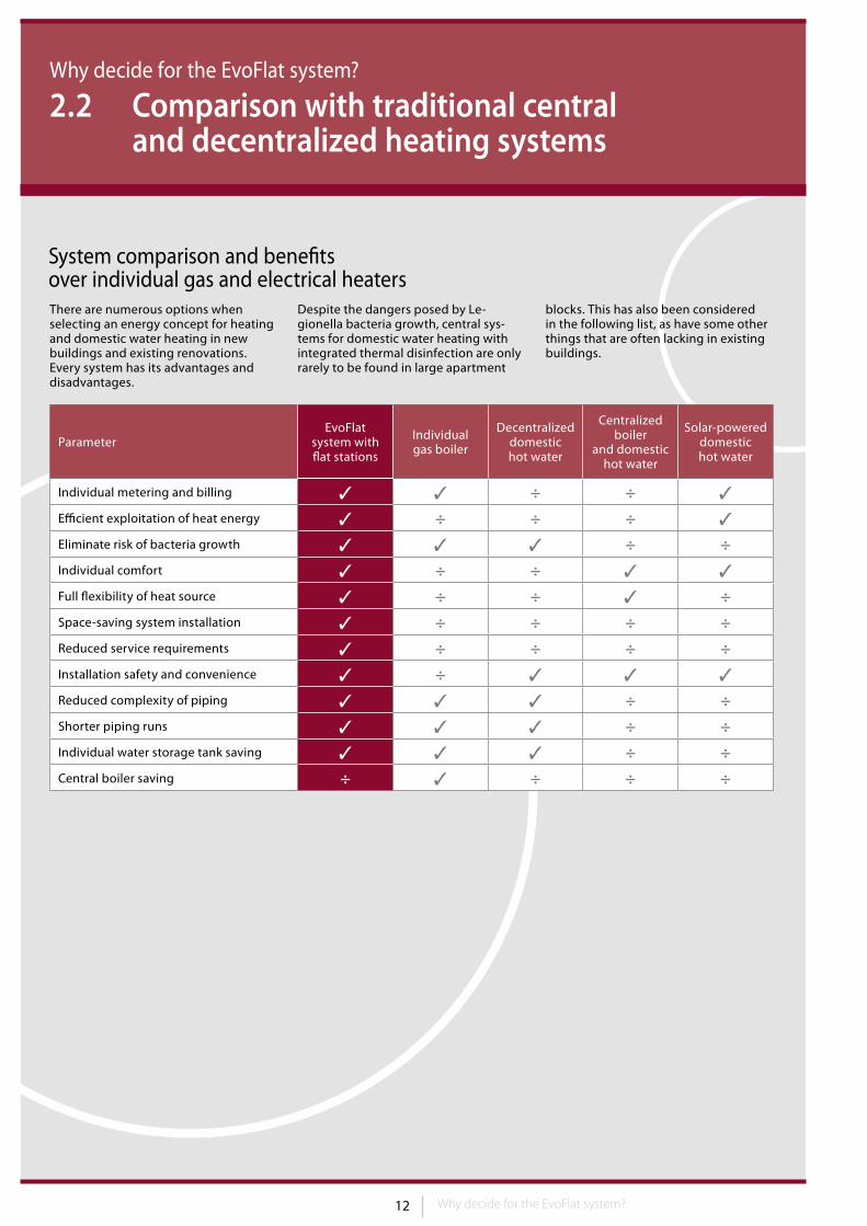
Individual metering and billing 3 3 ÷ ÷ 3
Efficient exploitation of heat energy 3 ÷ ÷ ÷ 3
Eliminate risk of bacteria growth 3 3 3 ÷ ÷Individual comfort 3 ÷ ÷ 3 3
Full flexibility of heat source 3 ÷ ÷ 3 ÷Space-saving system installation 3 ÷ ÷ ÷ ÷Reduced service requirements 3 ÷ ÷ ÷ ÷Installation safety and convenience 3 ÷ 3 3 3
Reduced complexity of piping 3 3 3 ÷ ÷Shorter piping runs 3 3 3 ÷ ÷Individual water storage tank saving 3 3 3 ÷ ÷Central boiler saving ÷ 3 ÷ ÷ ÷
System comparison and benefits over individual gas and electrical heaters There are numerous options when select ing an energy concept for heating and domestic water heating in new buildings and existing renovations. Every system has its advantages and disadvantages.
Despite the dangers posed by Le-gionella bacteria growth, central sys-tems for domestic water heating with integrated thermal disinfection are only rarely to be found in large apartment
blocks. This has also been considered in the following list, as have some other things that are often lacking in existing buildings.
13 Why decide for the EvoFlat system?
Why decide for the EvoFlat system?
2.3 Significant benefits with EvoFlat
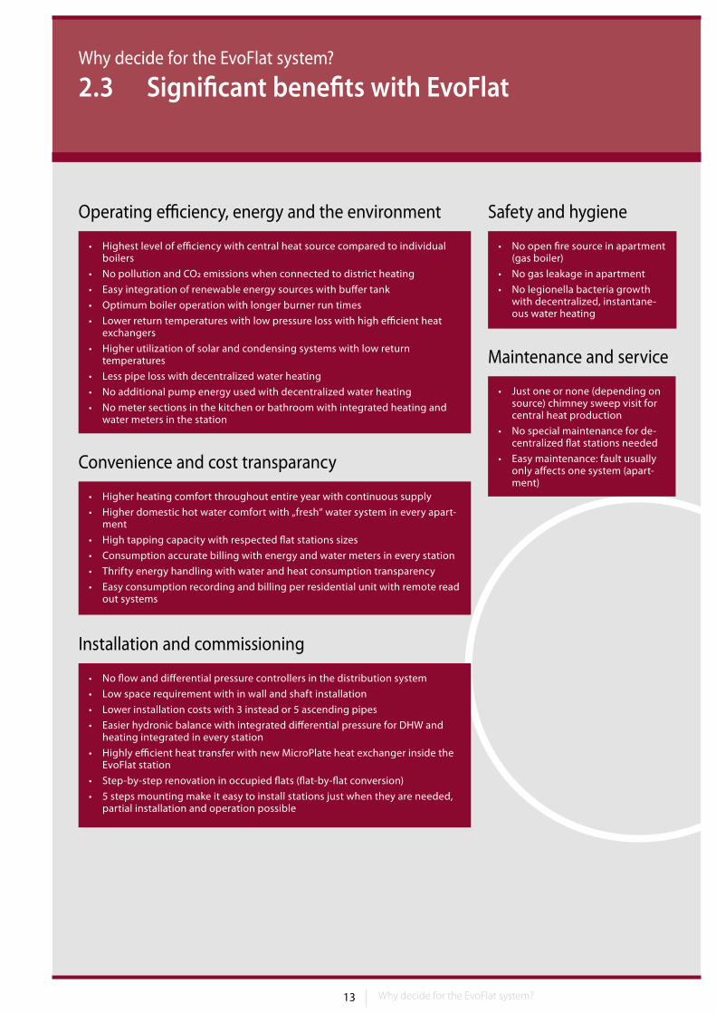
Operating efficiency, energy and the environment
• Highest level of efficiency with central heat source compared to individual boilers
• No pollution and CO2 emissions when connected to district heating
• Easy integration of renewable energy sources with buffer tank
• Optimum boiler operation with longer burner run times
• Lower return temperatures with low pressure loss with high efficient heat exchangers
• Higher utilization of solar and condensing systems with low return temperatures
• Less pipe loss with decentralized water heating
• No additional pump energy used with decentralized water heating
• No meter sections in the kitchen or bathroom with integrated heating and water meters in the station
Convenience and cost transparancy
• Higher heating comfort throughout entire year with continuous supply
• Higher domestic hot water comfort with „fresh“ water system in every apart-ment
• High tapping capacity with respected flat stations sizes
• Consumption accurate billing with energy and water meters in every station
• Thrifty energy handling with water and heat consumption transparency
• Easy consumption recording and billing per residential unit with remote read out systems
Installation and commissioning
• No flow and differential pressure controllers in the distribution system
• Low space requirement with in wall and shaft installation
• Lower installation costs with 3 instead or 5 ascending pipes
• Easier hydronic balance with integrated differential pressure for DHW and heating integrated in every station
• Highly efficient heat transfer with new MicroPlate heat exchanger inside the EvoFlat station
• Step-by-step renovation in occupied flats (flat-by-flat conversion)
• 5 steps mounting make it easy to install stations just when they are needed, partial installation and operation possible
Safety and hygiene
• No open fire source in apartment (gas boiler)
• No gas leakage in apartment
• No legionella bacteria growth with decentralized, instantane-ous water heating
Maintenance and service
• Just one or none (depending on source) chimney sweep visit for central heat production
• No special maintenance for de-centralized flat stations needed
• Easy maintenance: fault usually only affects one system (apart-ment)
14 15
3. What is the EvoFlat system solution?
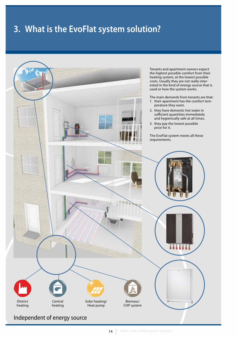
District heating
Centralheating
Solar heating/Heat pump
Biomass/ CHP system
Independent of energy source
Tenants and apartment owners expect the highest possible comfort from their heating system, at the lowest possible costs. Usually they are not really inter-ested in the kind of energy source that is used or how the system works.
The main demands from tenants are that:1. their apartment has the comfort tem-
perature they want,
2. they have domestic hot water in sufficient quantities immediately and hygienically safe at all times,
3. they pay the lowest possible price for it.
The EvoFlat system meets all these requirements.
What is the EvoFlat system solution
15
What is the EvoFlat system solution?
3.1 The function of the EvoFlat station
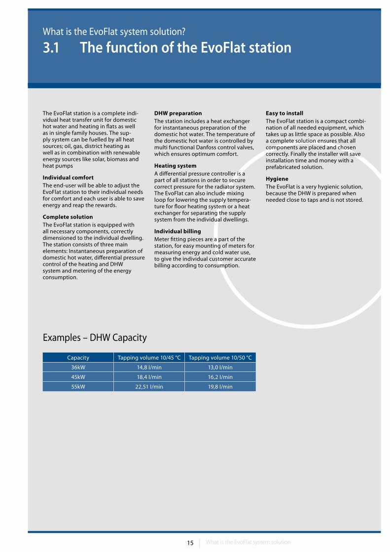
The EvoFlat station is a complete indi-vidual heat transfer unit for domestic hot water and heating in flats as well as in single family houses. The sup-ply system can be fuelled by all heat sources; oil, gas, district heating as well as in combination with renewable energy sources like solar, biomass and heat pumps
Individual comfortThe end-user will be able to adjust the EvoFlat station to their individual needs for comfort and each user is able to save energy and reap the rewards.
Complete solution The EvoFlat station is equipped with all necessary components, correctly dimensioned to the individual dwelling . The station consists of three main elements : Instantaneous preparation of domestic hot water, differential pressure control of the heating and DHW system and metering of the energy consumption .
DHW preparationThe station includes a heat exchanger for instantaneous preparation of the domestic hot water. The temperature of the domestic hot water is controlled by multi functional Danfoss control valves, which ensures optimum comfort.
Heating systemA differential pressure controller is a part of all stations in order to secure correct pressure for the radiator system. The EvoFlat can also include mixing loop for lowering the supply tempera-ture for floor heating system or a heat exchanger for separating the supply system from the individual dwellings.
Individual billingMeter fitting pieces are a part of the station, for easy mounting of meters for measuring energy and cold water use, to give the individual customer accurate billing according to consumption.
Easy to installThe EvoFlat station is a compact combi-nation of all needed equipment, which takes up as little space as possible. Also a complete solution ensures that all components are placed and chosen correctly. Finally the installer will save installation time and money with a prefabricated solution.
HygieneThe EvoFlat is a very hygienic solution, because the DHW is prepared when needed close to taps and is not stored.
Capacity Tapping volume 10/45 °C Tapping volume 10/50 °C
36kW 14,8 I/min 13,0 I/min
45kW 18,4 I/min 16,2 I/min
55kW 22,51 I/min 19,8 I/min
Examples – DHW Capacity
What is the EvoFlat system solution
16 17
6
6
6
7
7
7
2
34
OR
What is the EvoFlat system solution?
3.2 Main elements of the decentralized system
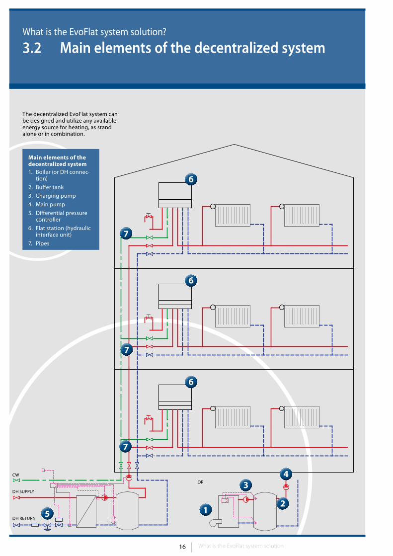
Main elements of the decentralized system1. Boiler (or DH connec-
tion)
2. Buffer tank
3. Charging pump
4. Main pump
5. Differential pressure controller
6. Flat station (hydraulic interface unit)
7. Pipes
The decentralized EvoFlat system can be designed and utilize any available energy source for heating, as stand alone or in combination.
CW
DH SUPPLy
DH RETURN5 1
What is the EvoFlat system solution
17
What is the EvoFlat system solution?
3.3 Independent of the available energy source
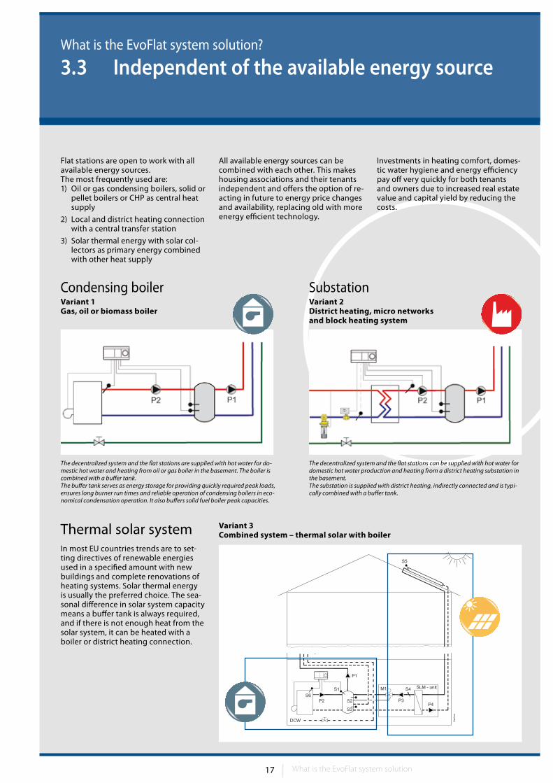
Variant 3 Combined system – thermal solar with boiler
Flat stations are open to work with all available energy sources. The most frequently used are:1) Oil or gas condensing boilers, solid or
pellet boilers or CHP as central heat supply
2) Local and district heating connection with a central transfer station
3) Solar thermal energy with solar col-lectors as primary energy combined with other heat supply
All available energy sources can be combined with each other. This makes housing associations and their tenants independent and offers the option of re-acting in future to energy price changes and availability, replacing old with more energy efficient technology.
Investments in heating comfort, domes-tic water hygiene and energy efficiency pay off very quickly for both tenants and owners due to increased real estate value and capital yield by reducing the costs.
Thermal solar systemIn most EU countries trends are to set-ting directives of renewable energies used in a specified amount with new buildings and complete renovations of heating systems. Solar thermal energy is usually the preferred choice. The sea-sonal difference in solar system capacity means a buffer tank is always required, and if there is not enough heat from the solar system, it can be heated with a boiler or district heating connection.
Variant 2 District heating, micro networks and block heating system
Variant 1 Gas, oil or biomass boiler
Condensing boiler Substation
The decentralized system and the flat stations are supplied with hot water for do-mestic hot water and heating from oil or gas boiler in the basement. The boiler is combined with a buffer tank. The buffer tank serves as energy storage for providing quickly required peak loads, ensures long burner run times and reliable operation of condensing boilers in eco-nomical condensation operation. It also buffers solid fuel boiler peak capacities.
The decentralized system and the flat stations can be supplied with hot water for domestic hot water production and heating from a district heating substation in the basement.The substation is supplied with district heating, indirectly connected and is typi-cally combined with a buffer tank.
What is the EvoFlat system solution
18 19
What is the EvoFlat system solution?
3.4 Hydronic balancing of the EvoFlat system
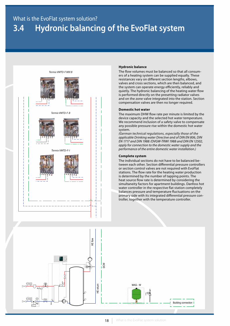
Hydronic balanceThe flow volumes must be balanced so that all consum-ers of a heating system can be supplied equally. These resistances vary on different section lengths, elbows, valves and cross sections, which are then balanced, and the system can operate energy efficiently, reliably and quietly. The hydronic balancing of the heating water flow is performed directly on the presetting radiator valves and on the zone valve integrated into the station. Section compensation valves are then no longer required.
Domestic hot waterThe maximum DHW flow rate per minute is limited by the device capacity and the selected hot water temperature. We recommend inclusion of a safety valve to compensate any possible pressure rise within the domestic hot water system. (German technical regulations, especially those of the applicable Drinking water Directive and of DIN EN 806, DIN EN 1717 and DIN 1988 /DVGW-TRWI 1988 and DIN EN 12502, apply for connection to the domestic water supply and the performance of the entire domestic water installation.)
Complete systemThe individual sections do not have to be balanced be-tween each other. Section differential pressure controllers or section control valves are not required with EvoFlat stations. The flow rate for the heating water production is determined by the number of tapping points. The heat source flow rate is determined by considering the simultaneity factors for apartment buildings. Danfoss hot water controller in the respective flat station completely balances pressure and temperature fluctuations on the primary side with its integrated differential pressure con-troller, together with the temperature controller.
Termix VMTD-F MIX B
Termix VMTD-F-B
Termix VMTD-F-I
What is the EvoFlat system solution
19
Distribution system must ensure that thermal energy is available for the con-sumer at all times and loads, at the right temperature and the right differential pressure.
The required differential pressure must be ensured at all relevant points of a distribution system, beginning with the energy production, right through to the least favorable radiator. Installation of a differential pressure controller in the apartment heating circuit guarantees fault free hydronic conditions.
A strong opinion, which still exists around, that a heating system can be properly balanced with section manual balancing valves and regulated pumps once again proved to be erroneous in practice.
In addition to a correctly set differential pressure controller for the apartment heating circuit, the individual radiator valves must also be correctly preset. Standard compliant differential pres-sures in front of the radiator valves now make flow noises a thing of the past.
The heating side connection is made without any system separation. The heating circuit supply must be fitted with a differential pressure controller to guarantee optimum pressure conditions and flows in the heating system. The room temperature is controlled with radiator thermostats. With the mount-ing of a thermal actuator with installed zone valve and using central manual or programmable room thermostat enables a convenient, energy optimized control of the heating.
21°C
21°C 21°C
21°C 21°C
21°C
21°C 21°C 21°C
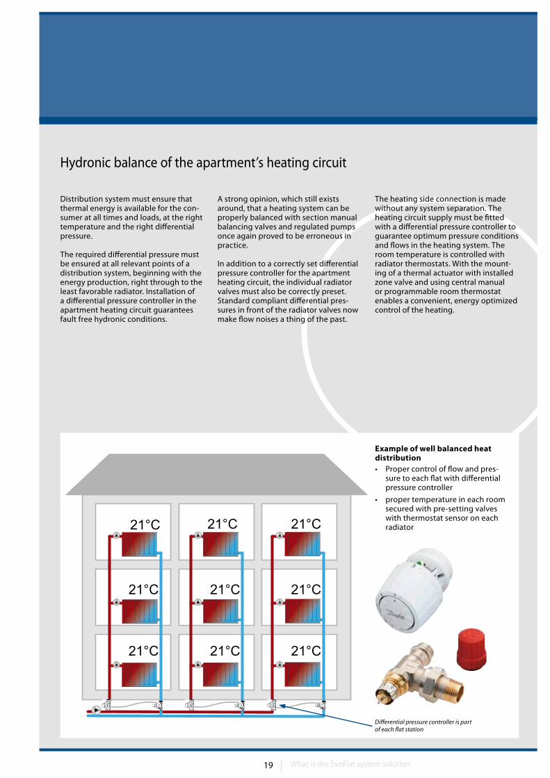
Differential pressure controller is part of each flat station
Example of well balanced heat distribution• Proper control of flow and pres-
sure to each flat with differential pressure controller
• proper temperature in each room secured with pre-setting valves with thermostat sensor on each radiator
Hydronic balance of the apartment’s heating circuit
What is the EvoFlat system solution
20 21
61
2
4
4
3
7
5
What is the EvoFlat system solution?
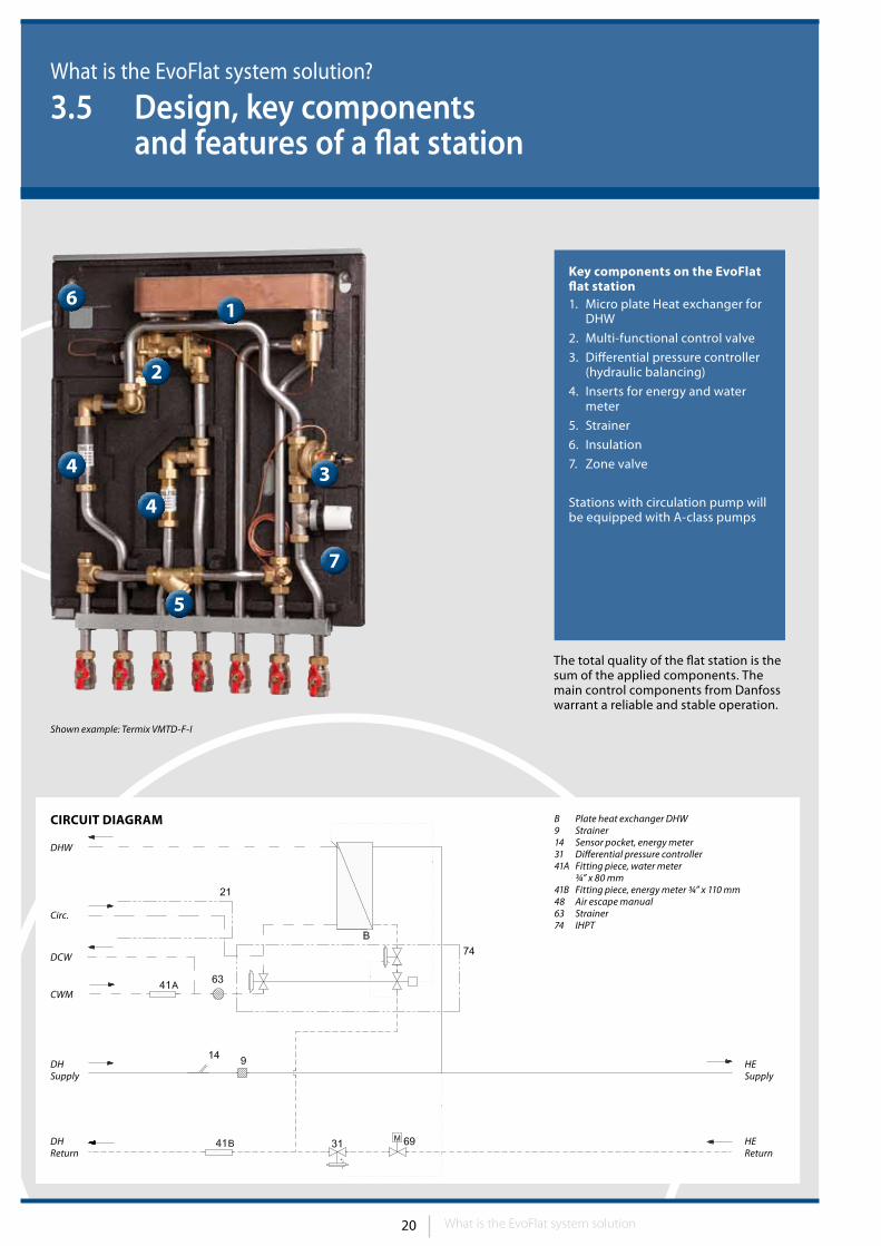
3.5 Design, key components and features of a flat station
Key components on the EvoFlat flat station 1. Micro plate Heat exchanger for
DHW
2. Multi-functional control valve
3. Differential pressure controller (hydraulic balancing)
4. Inserts for energy and water meter
5. Strainer
6. Insulation
7. Zone valve
Stations with circulation pump will be equipped with A-class pumps
Shown example: Termix VMTD-F-I
The total quality of the flat station is the sum of the applied components. The main control components from Danfoss warrant a reliable and stable operation.
CIRCuIT DIAGRAM B Plate heat exchanger DHW9 Strainer14 Sensor pocket, energy meter31 Differential pressure controller41A Fitting piece, water meter ¾” x 80 mm41B Fitting piece, energy meter ¾” x 110 mm48 Air escape manual63 Strainer74 IHPT
DHReturn
DCW
Circ.
DHW
HEReturn
HESupply
CWM
DHSupply
What is the EvoFlat system solution
21
What is the EvoFlat system solution?
3.5.1 Brazed plate heat exchangers
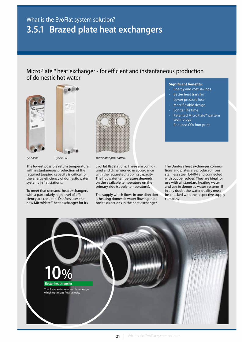
Significant benefits:- Energy and cost savings
- Better heat transfer
- Lower pressure loss
- More flexible design
- Longer life time
- Patented MicroPlate™ pattern technology
- Reduced CO2 foot print
MicroPlate™ heat exchanger - for efficient and instantaneous production of domestic hot water
10%Thanks to an innovative plate designwhich optimizes flow velocity
Better heat transfer
MicroPlate™ plate pattern
The lowest possible return temperature with instantaneous production of the required tapping capacity is critical for the energy efficiency of domestic water systems in flat stations.
To meet that demand, heat exchangers with a particularly high level of effi-ciency are required. Danfoss uses the new MicroPlate™ heat exchanger for its
EvoFlat flat stations. These are config-ured and dimensioned in accordance with the requested tapping capacity. The hot water temperature depends on the available temperature on the primary side (supply temperature).
The supply which flows in one direction is heating domestic water flowing in op-posite directions in the heat exchanger.
The Danfoss heat exchanger connec-tions and plates are produced from stainless steel 1.4404 and connected with copper solder. They are ideal for use with all standard heating water and use in domestic water systems. If in any doubt the water quality must be checked with the respective supply company.
Type XB06 Type XB 37
What is the EvoFlat system solution
22 23
What is the EvoFlat system solution?
3.5.2 Domestic hot water control valve – Introduction
A multi-functional DHW control valve inside EvoFlat!
Main features and benefits of the DHW controller
During tappingWhen domestic hot water is needed the DHW control valve opens and the heat exchanger heats the cold waterto the desired temperature. The sensor of the DHW control valve is placed in the heat exchanger and the valve maintains the temperature of DHW according to the temperature set on the thermostat part of the valve. The temperature
is kept stable independently of the changes in tapping flow, differential pressure and supply temperature.
Quick closingWhen the demand for DHW stops the valve must close quickly in order to protect the heat exchanger against overheating and lime scale formation.
Idle modeThe EvoFlat is delivered with a summer bypass to keep the house supply line warm. This shortens the waiting periods during summer when the heating system is in reduced operation.
Intelligent control with thermostatic override The IHPT controller controls the do-mestic hot water by taking both flow volume and temperature into account. By tapping the valves opens and the thermostat start to control the DHW temperature.
The control is independent of vary-ing flow temperatures and differential
pressure. When tapping ends, the valve closes immediately. This protects the heat exchanger from scaling.
Key features of IHPT:• Optimum control performance• Integrated standby function• Suitable for low temperature operation• Instant availability of water leads to minimum water waste
What is the EvoFlat system solution
23
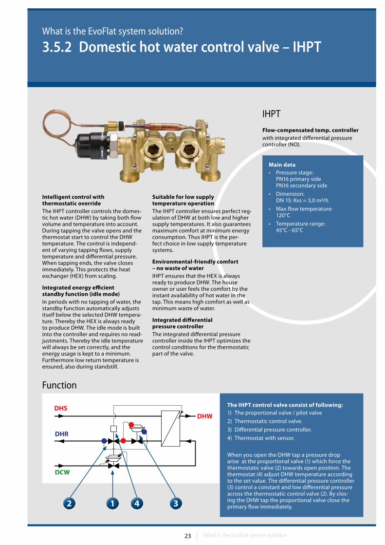
Main data• Pressure stage:
PN16 primary side PN16 secondary side
• Dimension: DN 15: Kvs = 3,0 m3/h
• Max flow temperature: 120°C
• Temperature range: 45°C - 65°C
What is the EvoFlat system solution?
3.5.2 Domestic hot water control valve – IHPT
Function
The IHPT control valve consist of following:1) The proportional valve / pilot valve
2) Thermostatic control valve.
3) Differential pressure controller.
4) Thermostat with sensor.
When you open the DHW tap a pressure drop arise at the proportional valve (1) which force the thermostatic valve (2) towards open position. The thermostat (4) adjust DHW temperature according to the set value. The differential pressure controller (3) control a constant and low differential pressure across the thermostatic control valve (2). By clos-ing the DHW tap the proportional valve close the primary flow immediately.
2
12 34
IHPT
Flow-compensated temp. controllerwith integrated differential pressure controller (NO).
Intelligent control with thermostatic overrideThe IHPT controller controls the domes-tic hot water (DHW) by taking both flow volume and temperature into account. During tapping the valve opens and the thermostat start to control the DHW temperature. The control is independ-ent of varying tapping flows, supply temperature and differential pressure. When tapping ends, the valve closes immediately. This protects the heat exchanger (HEX) from scaling.
Integrated energy efficient standby function (idle mode)In periods with no tapping of water, the standby function automatically adjusts itself below the selected DHW tempera-ture. Thereby the HEX is always ready to produce DHW. The idle mode is built into the controller and requires no read-justments. Thereby the idle temperature will always be set correctly, and the energy usage is kept to a minimum. Furthermore low return temperature is ensured, also during standstill.
Suitable for low supply temperature operationThe IHPT controller ensures perfect reg-ulation of DHW at both low and higher supply temperatures. It also guarantees maximum comfort at minimum energy consumption. Thus IHPT is the per-fect choice in low supply temperature systems.
Environmental-friendly comfort – no waste of waterIHPT ensures that the HEX is always ready to produce DHW. The house owner or user feels the comfort by the instant availability of hot water in the tap. This means high comfort as well as minimum waste of water.
Integrated differential pressure controllerThe integrated differential pressure controller inside the IHPT optimizes the control conditions for the thermostatic part of the valve.
What is the EvoFlat system solution
24 25
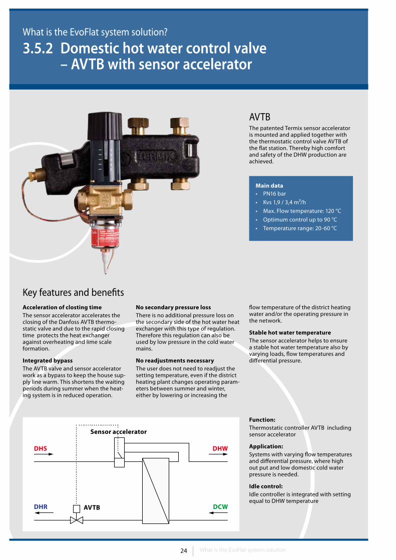
Main data• PN16 bar
• Kvs 1,9 / 3,4 m3/h
• Max. Flow temperature: 120 °C
• Optimum control up to 90 °C
• Temperature range: 20-60 °C
What is the EvoFlat system solution?
3.5.2 Domestic hot water control valve – AVTB with sensor accelerator
The patented Termix sensor accelerator is mounted and applied together with the thermostatic control valve AVTB of the flat station. Thereby high comfort and safety of the DHW production are achieved.
Function:Thermostatic controller AVTB including sensor accelerator
Application:Systems with varying flow temperatures and differential pressure, where high out put and low domestic cold water pressure is needed.
Idle control:Idle controller is integrated with setting equal to DHW temperature
Acceleration of closting timeThe sensor accelerator accelerates the closing of the Danfoss AVTB thermo-static valve and due to the rapid closing time protects the heat exchanger against overheating and lime scale formation.
Integrated bypassThe AVTB valve and sensor accelerator work as a bypass to keep the house sup-ply line warm. This shortens the waiting periods during summer when the heat-ing system is in reduced operation.
No secondary pressure lossThere is no additional pressure loss on the secondary side of the hot water heat exchanger with this type of regulation. Therefore this regulation can also be used by low pressure in the cold water mains.
No readjustments necessaryThe user does not need to readjust the setting temperature, even if the district heating plant changes operating param-eters between summer and winter, either by lowering or increasing the
flow temperature of the district heating water and/or the operating pressure in the network.
Stable hot water temperatureThe sensor accelerator helps to ensure a stable hot water temperature also by varying loads, flow temperatures and differential pressure.
Key features and benefits
AVTB
DHR DCWAVTB
DHS DHW
Sensor accelerator
What is the EvoFlat system solution
25
What is the EvoFlat system solution?
3.5.3 Additional flat station components
For users with higher demands for comfort it is possible to use program-mable thermostats TP5001 with a weekly program (5/2) and TP7000 with a daily program (6 intervals), and with the possibility of lowering the night temperature.
Piping and connectionsAll elements built into flat station are connected by pipes made of stainless steel. Extremely low roughness of pipe and special way of bending ensures silent operation and small dimensions of the stations. Connection elements used are made from brass (connection fittings, elbows and T-pieces). All ele-ments in the flat stations are connected with detachable fittings to allow easy replacement of parts and easy mainte-nance. Rated nominal pressure of flat stations is PN 10 (16) as standard.
OptionsAll flat stations can be equipped with domestic hot water circulation set on request. It consists of the pump with timer, thermostat or both and the re-quired connection lines.
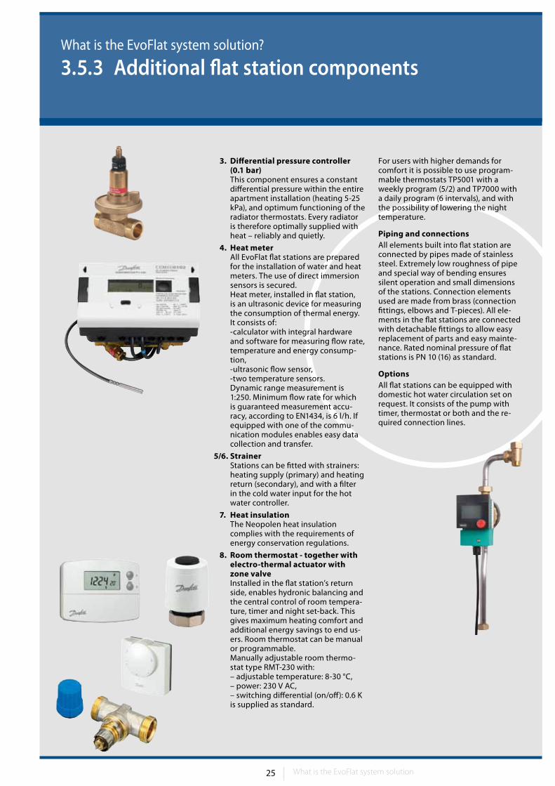
3. Differential pressure controller (0.1 bar)This component ensures a constant differential pressure within the entire apartment installation (heating 5-25 kPa), and optimum functioning of the radiator thermostats. Every radiator is therefore optimally supplied with heat – reliably and quietly.
4. Heat meter All EvoFlat flat stations are prepared for the installation of water and heat meters. The use of direct immersion sensors is secured. Heat meter, installed in flat station, is an ultrasonic device for measuring the consumption of thermal energy. It consists of: -calculator with integral hardware and software for measuring flow rate, temperature and energy consump-tion, -ultrasonic flow sensor, -two temperature sensors. Dynamic range measurement is 1:250. Minimum flow rate for which is guaranteed measurement accu-racy, according to EN1434, is 6 l/h. If equipped with one of the commu-nication modules enables easy data collection and transfer.
5/6. Strainer Stations can be fitted with strainers: heating supply (primary) and heating return (secondary), and with a filter in the cold water input for the hot water controller.
7. Heat insulation The Neopolen heat insulation complies with the requirements of energy conservation regulations.
8. Room thermostat - together with electro-thermal actuator with zone valve Installed in the flat station’s return side, enables hydronic balancing and the central control of room tempera-ture, timer and night set-back. This gives maximum heating comfort and additional energy savings to end us-ers. Room thermostat can be manual or programmable. Manually adjustable room thermo-stat type RMT-230 with: – adjustable temperature: 8-30 °C, – power: 230 V AC, – switching differential (on/off): 0.6 K is supplied as standard.
What is the EvoFlat system solution
26 27
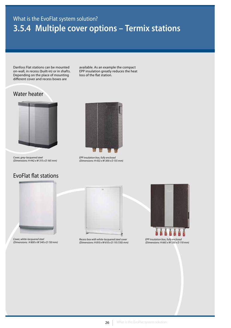
Danfoss Flat stations can be mounted on-wall, in recess (built-in) or in shafts.Depending on the place of mounting different cover and recess boxes are
available. As an example the compact EPP insulation greatly reduces the heat loss of the flat station.
What is the EvoFlat system solution
What is the EvoFlat system solution?
3.5.4 Multiple cover options – Termix stations
EPP insulation box, fully enclosed(Dimensions: H 665 x W 530 x D 110 mm)
Cover, white-lacquered steel(Dimensions: H 800 x W 540 x D 150 mm)
Cover, grey-lacquered steel(Dimensions: H 442 x W 315 x D 165 mm)
Recess box with white-lacquered steel cover(Dimensions: H 810 x W 610 x D 110 (150) mm)
EPP insulation box, fully enclosed(Dimensions: H 432 x W 300 x D 155 mm)
Water heater
EvoFlat flat stations
27
What is the EvoFlat system solution?
3.5.5 EvoFlat insulation options – Termix
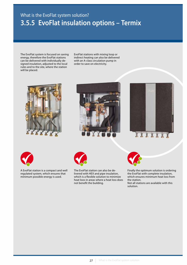
The EvoFlat system is focused on saving energy, therefore the EvoFlat stations can be delivered with individually de-signed insulation, adjusted to the local rules and to the site, where the station will be placed.
EvoFlat stations with mixing loop or indirect heating can also be delivered with an A-class circulation pump in order to save on electricity.
A EvoFlat station is a compact and wellregulated system, which ensures that minimum possible energy is used.
The EvoFlat station can also be de-livered with HEX and pipe insulation, which is a flexible solution to minimize heat loos in areas where a heat loss does not benefit the building.
Finally the optimum solution is ordering the EvoFlat with complete insulation, which ensures minimum heat loss from the station.Not all stations are available with this solution.
What is the EvoFlat system solution
28 29
What is the EvoFlat system solution?
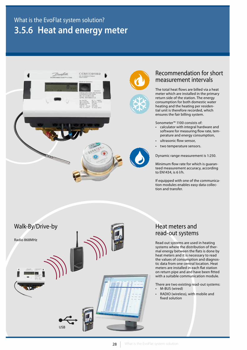
3.5.6 Heat and energy meter
Heat meters and read-out systemsRead out systems are used in heating systems where the distribution of ther-mal energy between the flats is done by heat meters and it is necessary to read the values of consumption and diagnos-tic data from one central location. Heat meters are installed in each flat station on return pipe and and have been fitted with a suitable communication module.
There are two existing read-out systems:• M-BUS (wired)
• RADIO (wireless), with mobile and fixed solution
Walk-By/Drive-by
Radio 868MHz
Recommendation for short measurement intervalsThe total heat flows are billed via a heat meter which are installed in the primary return side of the station. The energy consumption for both domestic water heating and the heating per residen-tial unit is therefore recorded, which ensures the fair billing system.
Sonometer™ 1100 consists of: • calculator with integral hardware and
software for measuring flow rate, tem-perature and energy consumption,
• ultrasonic flow sensor,
• two temperature sensors.
Dynamic range measurement is 1:250.
Minimum flow rate for which is guaran-teed measurement accuracy, according to EN1434, is 6 l/h.
If equipped with one of the communica-tion modules enables easy data collec-tion and transfer.
USB
What is the EvoFlat system solution
29
What is the EvoFlat system solution?
3.6 Domestic hot water requirements
Heating waterIn the past there were some norms how to fill heating systems with the usual local domestic water. The variety of materials used in heating systems today requires a precise analysis of the composition of the hot water used, and an appropriate preparation where re-quired, to prevent unwanted build ups and corrosion.
Scale, which occurs at specific tempera-tures and can build up on the elements of boilers or heat exchangers, is one
of the “problem substances” in hot water. Such deposits impair the heat ex changer’s efficiency and performance capacity, cause higher return tem-peratures and therefore reduce energy efficiency.
The use of suitable specialist companies is recommended for the analysis and preparation of the hot water. The pH value should also be checked regularly.
EvoFlat flat stations comply with EU heating water guidelines.
Domestic hot waterDanfoss EvoFlat flat stations comply with EU drinking water directives and norms (German: DVGW, DIN 1988, EN 1717, 805 and 806 and DVGW guidelines ).
What is the EvoFlat system solution
30 Introduction to the product range30 31
EvoFlat flat stations
4. Introduction to the product range
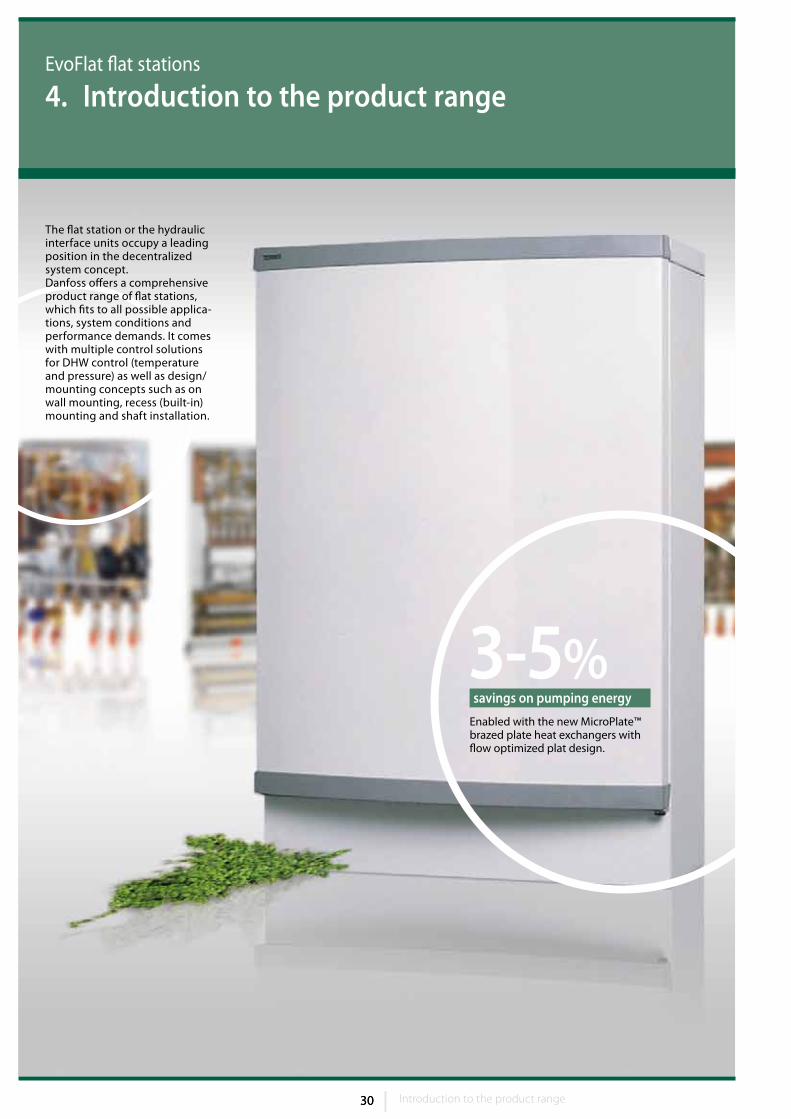
3-5%Enabled with the new MicroPlate™ brazed plate heat exchangers with flow optimized plat design.
savings on pumping energy
The flat station or the hydraulic interface units occupy a leading position in the decentralized system concept. Danfoss offers a comprehensive product range of flat stations, which fits to all possible applica-tions, system conditions and performance demands. It comes with multiple control solutions for DHW control (temperature and pressure) as well as design/mounting concepts such as on wall mounting, recess (built-in) mounting and shaft installation.
Introduction to the product range 31 Introduction to the product range
App
licat
ion/
Pr
oduc
t typ
e
Termix Novi
Termix One B
Termix VMTD
F-l
Termix VMTD
F-B
TermixVMTD-F
Mix-I
Termix VMTD-F-
Mix-B
Termix VVX-l
Termix VVX-B
Domestic hot water (DHW)
X X
Direct heating & DHW X X
Direct heating w/ mixing loop & DHW
X X
Indirect heating & DHW
X X
EvoFlat flat stations
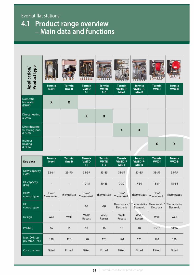
4.1 Product range overview – Main data and functions
Key dataTermix
NoviTermix One B
Termix VMTD
F-l
Termix VMTD
F-B
TermixVMTD-F
Mix-I
Termix VMTD-F-
Mix-B
Termix VVX-l
Termix VVX-B
DHW capacity ( kW) 32-61 29-90 33-59 33-85 33-59 33-85 33-59 33-75
HE capacity(kW) - - 10-15 10-35 7-30 7-30 18-54 18-54
DHWcontrol type
Flow/Thermostatic Thermostatic Flow/
Thermostatic Thermostatic Flow/ Thermostatic Thermostatic Flow/
Thermostatic Thermostatic
HEcontrol type - - Δp Δp Thermostatic/
ElectronicThermostatic/
ElectronicThermostatic/
ElectronicThermostatic/
Electronic
Design Wall Wall Wall/ Recess
Wall/ Recess
Wall/ Recess
Wall/ Recess Wall Wall
PN (bar) 16 16 10 16 10 10 10/16 10/16
Max. DH sup-ply temp. ( °C) 120 120 120 120 120 120 120 120
Construction Fitted Fitted Fitted Fitted Fitted Fitted Fitted Fitted
32 Introduction to the product range32 33
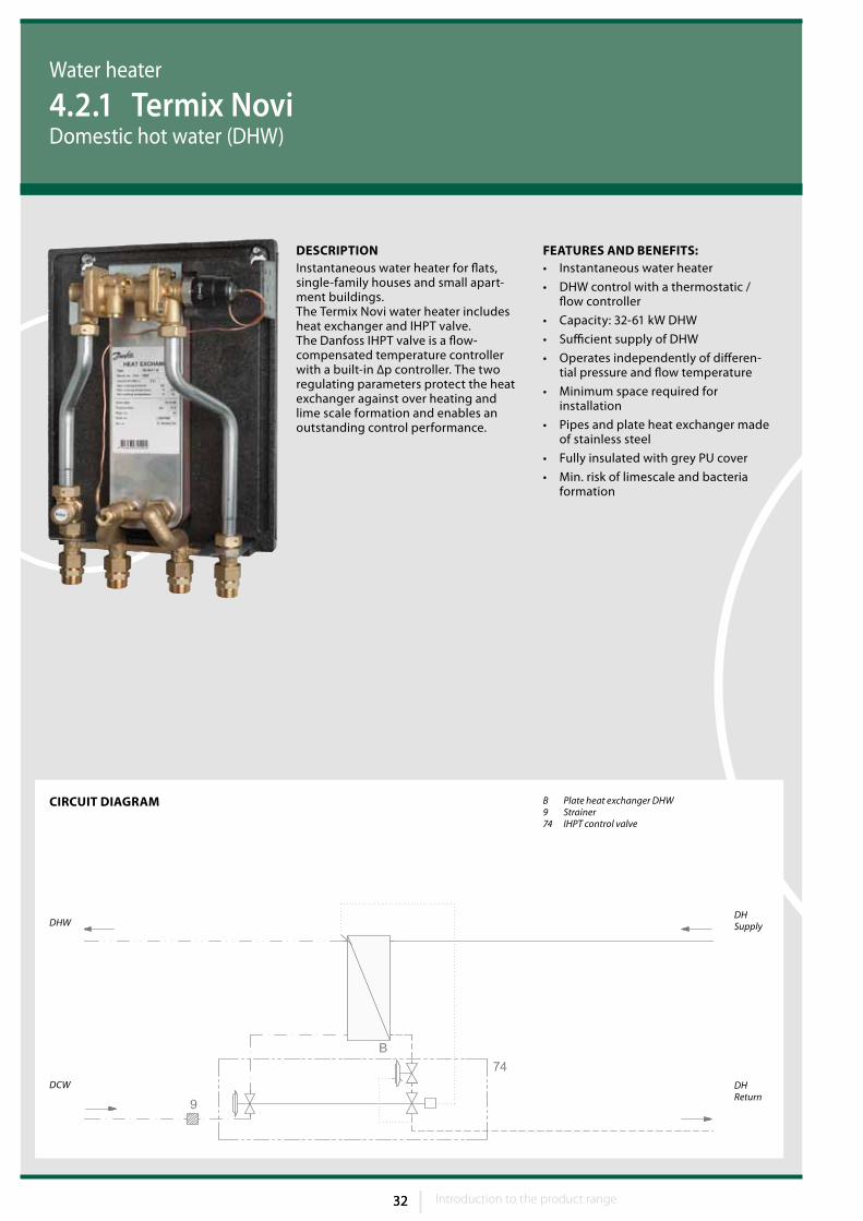
FEATuRES AND BENEFITS:• Instantaneous water heater
• DHW control with a thermostatic / flow controller
• Capacity: 32-61 kW DHW
• Sufficient supply of DHW
• Operates independently of differen-tial pressure and flow temperature
• Minimum space required for installation
• Pipes and plate heat exchanger made of stainless steel
• Fully insulated with grey PU cover
• Min. risk of limescale and bacteria formation
B Plate heat exchanger DHW 9 Strainer74 IHPT control valve
DHReturn
DCW
DHWDHSupply
CIRCuIT DIAGRAM
DESCRIPTIONInstantaneous water heater for flats, single-family houses and small apart-ment buildings.The Termix Novi water heater includes heat exchanger and IHPT valve. The Danfoss IHPT valve is a flow-compensated temperature controller with a built-in ∆p controller. The two regulating parameters protect the heat exchanger against over heating and lime scale formation and enables an outstanding control performance.
Water heater
4.2.1 Termix NoviDomestic hot water (DHW)
Introduction to the product range 33 Introduction to the product range
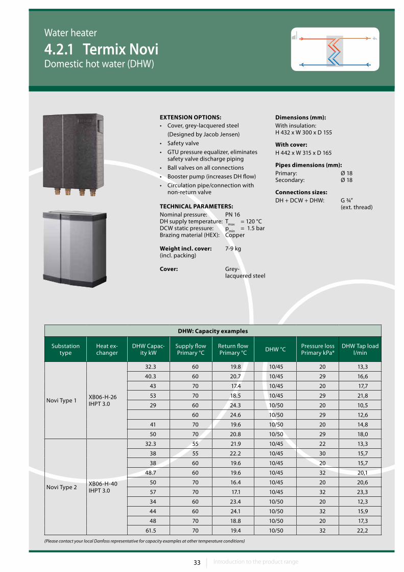
Dimensions (mm):With insulation:H 432 x W 300 x D 155
With cover:H 442 x W 315 x D 165
Pipes dimensions (mm):Primary: Ø 18Secondary: Ø 18
Connections sizes:DH + DCW + DHW: G ¾” (ext. thread)
Water heater
4.2.1 Termix NoviDomestic hot water (DHW)
EXTENSION OPTIONS:• Cover, grey-lacquered steel
(Designed by Jacob Jensen)
• Safety valve
• GTU pressure equalizer, eliminates safety valve discharge piping
• Ball valves on all connections
• Booster pump (increases DH flow)
• Circulation pipe/connection with non-return valve
TECHNICAL PARAMETERS:Nominal pressure: PN 16DH supply temperature: T
max = 120 °C
DCW static pressure: pmin
= 1.5 barBrazing material (HEX): Copper
Weight incl. cover: 7-9 kg(incl. packing)
Cover: Grey- lacquered steel
DHW: Capacity examples
Substation type
Heat ex-changer
DHW Capac-ity kW
Supply flow Primary °C
Return flow Primary °C DHW °C Pressure loss
Primary kPa*DHW Tap load
l/min
Novi Type 1 XB06-H-26 IHPT 3.0
32.3 60 19.8 10/45 20 13,3
40.3 60 20.7 10/45 29 16,6
43 70 17.4 10/45 20 17,7
53 70 18.5 10/45 29 21,8
29 60 24.3 10/50 20 10,5
60 24.6 10/50 29 12,6
41 70 19.6 10/50 20 14,8
50 70 20.8 10/50 29 18,0
Novi Type 2 XB06-H-40 IHPT 3.0
32.3 55 21.9 10/45 22 13,3
38 55 22.2 10/45 30 15,7
38 60 19.6 10/45 20 15,7
48.7 60 19.6 10/45 32 20,1
50 70 16.4 10/45 20 20,6
57 70 17.1 10/45 32 23,3
34 60 23.4 10/50 20 12,3
44 60 24.1 10/50 32 15,9
48 70 18.8 10/50 20 17,3
61.5 70 19.4 10/50 32 22,2
(Please contact your local Danfoss representative for capacity examples at other temperature conditions)
34 Introduction to the product range34 35
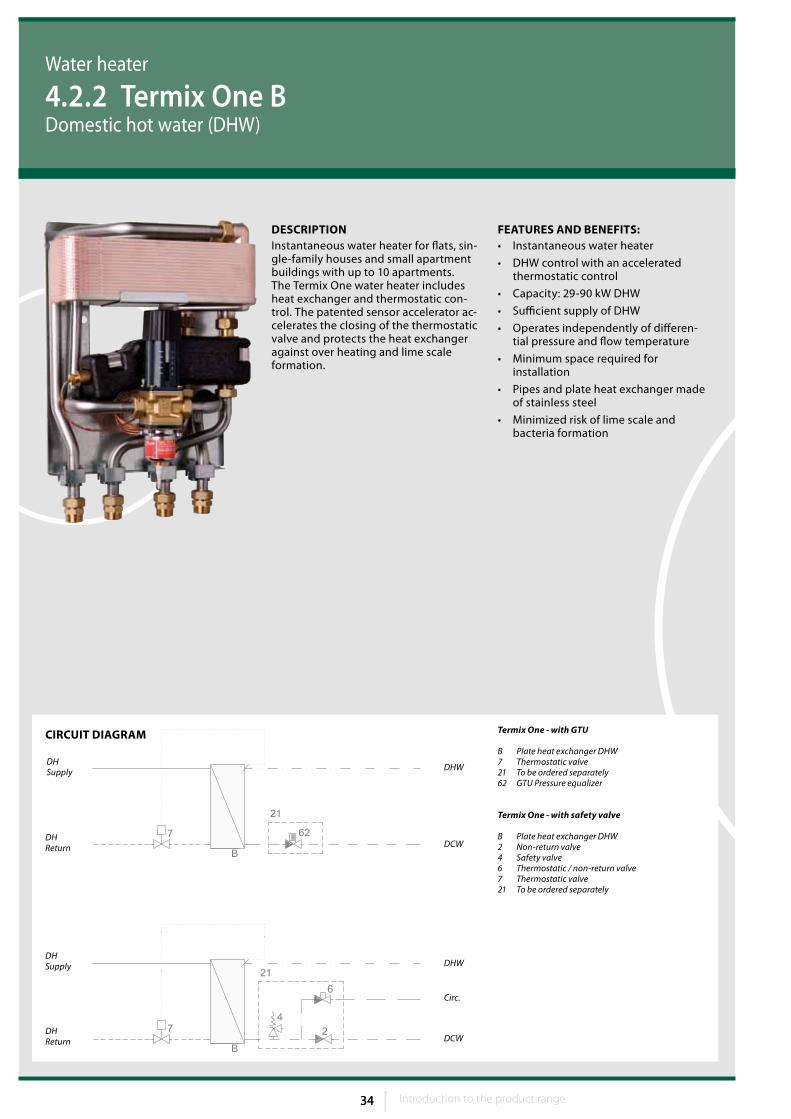
FEATuRES AND BENEFITS:• Instantaneous water heater
• DHW control with an accelerated thermostatic control
• Capacity: 29-90 kW DHW
• Sufficient supply of DHW
• Operates independently of differen-tial pressure and flow temperature
• Minimum space required for installation
• Pipes and plate heat exchanger made of stainless steel
• Minimized risk of lime scale and bacteria formation
CIRCuIT DIAGRAM Termix One - with GTU
B Plate heat exchanger DHW 7 Thermostatic valve21 To be ordered separately62 GTU Pressure equalizer
Termix One - with safety valve
B Plate heat exchanger DHW 2 Non-return valve4 Safety valve6 Thermostatic / non-return valve7 Thermostatic valve21 To be ordered separately
DHW
DCW
Circ.
DCWDHReturn
DHSupply
DHReturn
DHSupply
DHW
DESCRIPTIONInstantaneous water heater for flats, sin-gle-family houses and small apartment buildings with up to 10 apartments.The Termix One water heater includes heat exchanger and thermostatic con-trol. The patented sensor accelerator ac-celerates the closing of the thermostatic valve and protects the heat exchanger against over heating and lime scale formation.
Water heater
4.2.2 Termix One BDomestic hot water (DHW)
Introduction to the product range 35 Introduction to the product range
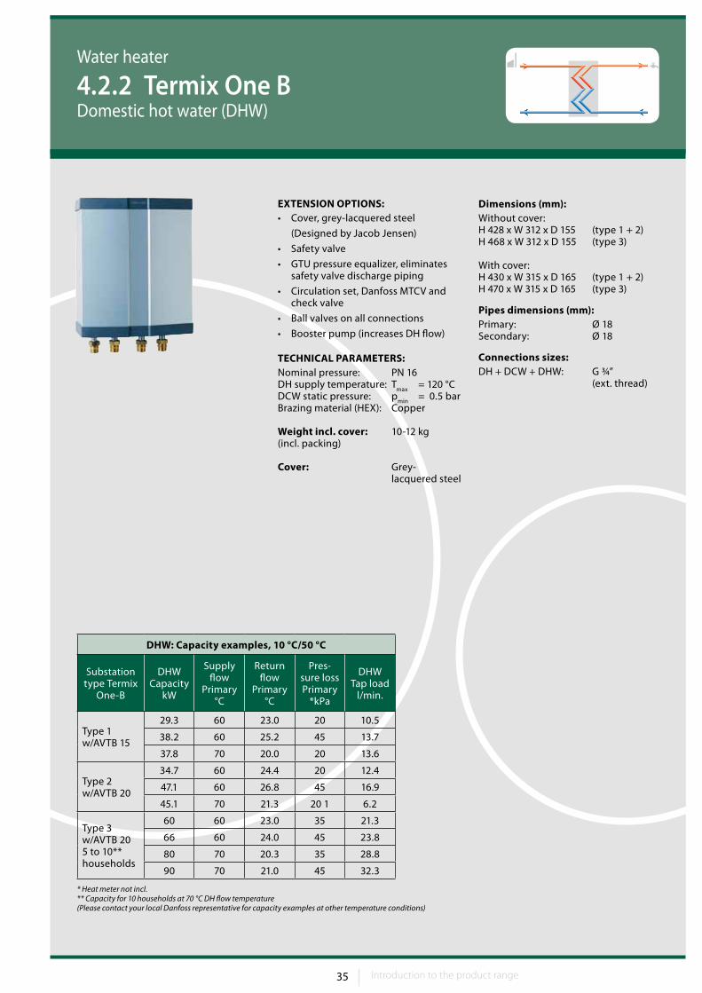
Dimensions (mm):Without cover:H 428 x W 312 x D 155 (type 1 + 2) H 468 x W 312 x D 155 (type 3)
With cover:H 430 x W 315 x D 165 (type 1 + 2) H 470 x W 315 x D 165 (type 3)
Pipes dimensions (mm):Primary: Ø 18Secondary: Ø 18
Connections sizes:DH + DCW + DHW: G ¾” (ext. thread)
Water heater
4.2.2 Termix One BDomestic hot water (DHW)
EXTENSION OPTIONS:• Cover, grey-lacquered steel
(Designed by Jacob Jensen)
• Safety valve
• GTU pressure equalizer, eliminates safety valve discharge piping
• Circulation set, Danfoss MTCV and check valve
• Ball valves on all connections
• Booster pump (increases DH flow)
TECHNICAL PARAMETERS:Nominal pressure: PN 16DH supply temperature: T
max = 120 °C
DCW static pressure: pmin
= 0.5 barBrazing material (HEX): Copper
Weight incl. cover: 10-12 kg(incl. packing)
Cover: Grey- lacquered steel
DHW: Capacity examples, 10 °C/50 °C
Substation type Termix
One-B
DHW Capacity
kW
Supply flow
Primary °C
Return flow
Primary °C
Pres-sure loss Primary
*kPa
DHW Tap load
l/min.
Type 1 w/AVTB 15
29.3 60 23.0 20 10.5
38.2 60 25.2 45 13.7
37.8 70 20.0 20 13.6
Type 2 w/AVTB 20
34.7 60 24.4 20 12.4
47.1 60 26.8 45 16.9
45.1 70 21.3 20 1 6.2
Type 3 w/AVTB 20 5 to 10** households
60 60 23.0 35 21.3
66 60 24.0 45 23.8
80 70 20.3 35 28.8
90 70 21.0 45 32.3
* Heat meter not incl.** Capacity for 10 households at 70 °C DH flow temperature(Please contact your local Danfoss representative for capacity examples at other temperature conditions)
36 Introduction to the product range36 37
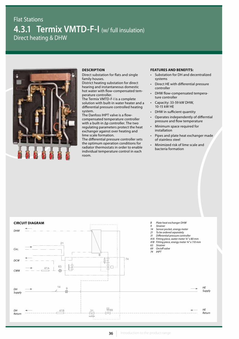
FEATuRES AND BENEFITS:• Substation for DH and decentralized
systems
• Direct HE with differential pressure controller
• DHW flow-compensated tempera-ture controller
• Capacity: 33-59 kW DHW, 10-15 kW HE
• DHW in sufficient quantity
• Operates independently of differntial pressure and flow temperature
• Minimum space required for installation
• Pipes and plate heat exchanger made of stainless steel
• Minimized risk of lime scale and bacteria formation
CIRCuIT DIAGRAM B Plate heat exchanger DHW9 Strainer14 Sensor pocket, energy meter21 To be ordered separately31 Differential pressure controller41A Fitting piece, water meter ¾” x 80 mm41B Fitting piece, energy meter ¾” x 110 mm63 Strainer69 On/off valve74 IHPT
DHSupply
DHReturn
CWM
DHW
HEReturn
HESupply
Circ.
DCW
DESCRIPTIONDirect substation for flats and single family houses.District heating substation for direct hearing and instantaneous domestic hot water with flow-compensated tem-perature controller.The Termix VMTD-F-I is a complete solution with built-in water heater and a differential pressure controlled heating system.The Danfoss IHPT valve is a flow-compensated temperature controller with a built-in ∆p controller. The two regulating parameters protect the heat exchanger against over heating and lime scale formation.The differential pressure controller sets the optimum operation conditions for radiator thermostats in order to enable individual temperature control in each room.
Flat Stations
4.3.1 Termix VMTD-F-I (w/ full insulation)Direct heating & DHW
Introduction to the product range 37 Introduction to the product range
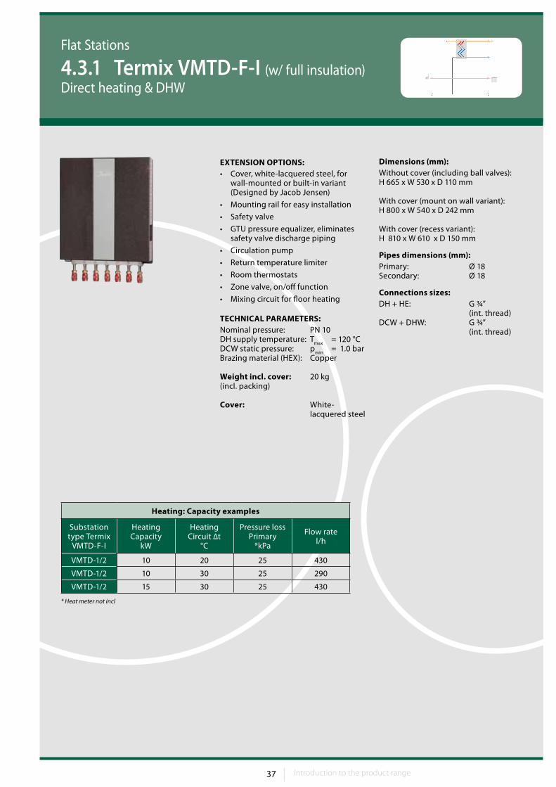
Dimensions (mm):Without cover (including ball valves):H 665 x W 530 x D 110 mm
With cover (mount on wall variant):H 800 x W 540 x D 242 mm
With cover (recess variant):H 810 x W 610 x D 150 mm
Pipes dimensions (mm):Primary: Ø 18 Secondary: Ø 18
Connections sizes:DH + HE: G ¾” (int. thread)DCW + DHW: G ¾” (int. thread)
Flat Stations
4.3.1 Termix VMTD-F-I (w/ full insulation)Direct heating & DHW
EXTENSION OPTIONS:• Cover, white-lacquered steel, for
wall-mounted or built-in variant (Designed by Jacob Jensen)
• Mounting rail for easy installation
• Safety valve
• GTU pressure equalizer, eliminates safety valve discharge piping
• Circulation pump
• Return temperature limiter
• Room thermostats
• Zone valve, on/off function
• Mixing circuit for floor heating
TECHNICAL PARAMETERS:Nominal pressure: PN 10DH supply temperature: T
max = 120 °C
DCW static pressure: pmin
= 1.0 barBrazing material (HEX): Copper
Weight incl. cover: 20 kg(incl. packing)
Cover: White- lacquered steel
Heating: Capacity examples
Substation type Termix
VMTD-F-I
Heating Capacity
kW
Heating Circuit ∆t
°C
Pressure lossPrimary
*kPa
Flow rate l/h
VMTD-1/2 10 20 25 430
VMTD-1/2 10 30 25 290
VMTD-1/2 15 30 25 430
* Heat meter not incl
38 Introduction to the product range38 39
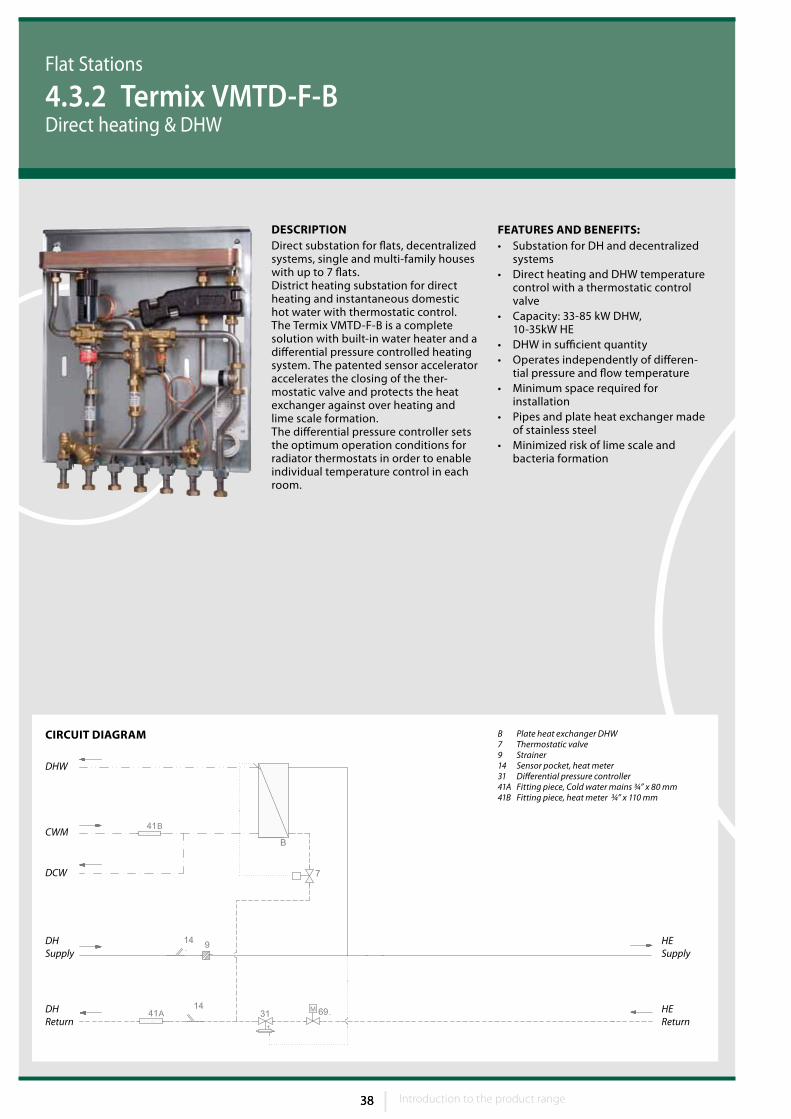
FEATuRES AND BENEFITS:• Substation for DH and decentralized
systems• Direct heating and DHW temperature
control with a thermostatic control valve
• Capacity: 33-85 kW DHW, 10-35kW HE
• DHW in sufficient quantity• Operates independently of differen-
tial pressure and flow temperature• Minimum space required for
installation • Pipes and plate heat exchanger made
of stainless steel• Minimized risk of lime scale and
bacteria formation
CIRCuIT DIAGRAM B Plate heat exchanger DHW7 Thermostatic valve9 Strainer14 Sensor pocket, heat meter31 Differential pressure controller41A Fitting piece, Cold water mains ¾” x 80 mm41B Fitting piece, heat meter ¾” x 110 mm
DHSupply
DHReturn
DCW
CWM
DHW
HEReturn
HESupply
DESCRIPTIONDirect substation for flats, decentralized systems, single and multi-family houses with up to 7 flats.District heating substation for direct heating and instantaneous domestic hot water with thermostatic control. The Termix VMTD-F-B is a complete solution with built-in water heater and a differential pressure controlled heating system. The patented sensor accelerator accelerates the closing of the ther-mostatic valve and protects the heat exchanger against over heating and lime scale formation.The differential pressure controller sets the optimum operation conditions for radiator thermostats in order to enable individual temperature control in each room.
Flat Stations
4.3.2 Termix VMTD-F-BDirect heating & DHW
Introduction to the product range 39 Introduction to the product range
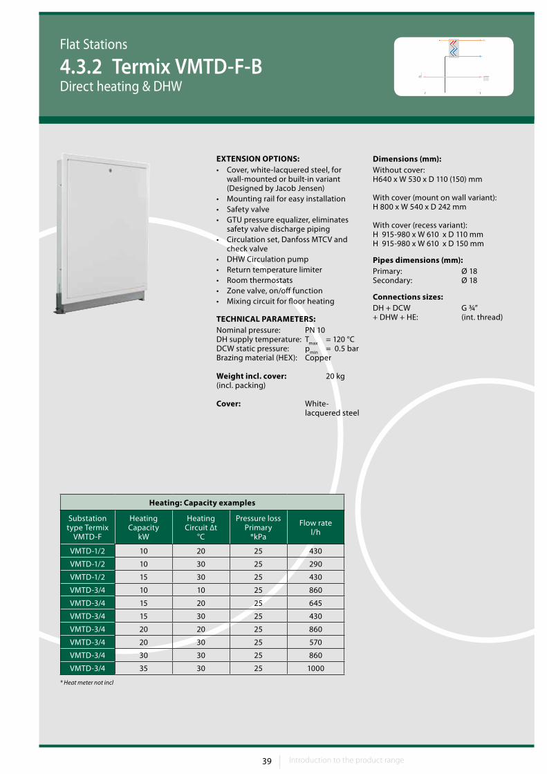
Dimensions (mm):Without cover:H640 x W 530 x D 110 (150) mm
With cover (mount on wall variant):H 800 x W 540 x D 242 mm
With cover (recess variant):H 915-980 x W 610 x D 110 mm H 915-980 x W 610 x D 150 mm
Pipes dimensions (mm):Primary: Ø 18 Secondary: Ø 18
Connections sizes:DH + DCW G ¾” + DHW + HE: (int. thread)
Flat Stations
4.3.2 Termix VMTD-F-BDirect heating & DHW
EXTENSION OPTIONS:• Cover, white-lacquered steel, for
wall-mounted or built-in variant (Designed by Jacob Jensen)
• Mounting rail for easy installation • Safety valve• GTU pressure equalizer, eliminates
safety valve discharge piping • Circulation set, Danfoss MTCV and
check valve • DHW Circulation pump• Return temperature limiter• Room thermostats• Zone valve, on/off function• Mixing circuit for floor heating
TECHNICAL PARAMETERS:Nominal pressure: PN 10DH supply temperature: T
max = 120 °C
DCW static pressure: pmin
= 0.5 barBrazing material (HEX): Copper
Weight incl. cover: 20 kg(incl. packing)
Cover: White- lacquered steel
Heating: Capacity examples
Substation type Termix
VMTD-F
Heating Capacity
kW
Heating Circuit ∆t
°C
Pressure loss Primary
*kPa
Flow rate l/h
VMTD-1/2 10 20 25 430
VMTD-1/2 10 30 25 290
VMTD-1/2 15 30 25 430
VMTD-3/4 10 10 25 860
VMTD-3/4 15 20 25 645
VMTD-3/4 15 30 25 430
VMTD-3/4 20 20 25 860
VMTD-3/4 20 30 25 570
VMTD-3/4 30 30 25 860
VMTD-3/4 35 30 25 1000
* Heat meter not incl
40 Introduction to the product range40 41
CIRCuIT DIAGRAM
CWM
DCW
DHSupply
DHReturn
HEsupply
HEreturn
DHW
Flat Stations
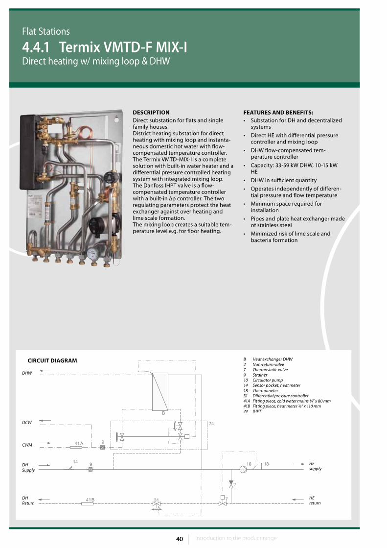
4.4.1 Termix VMTD-F MIX-IDirect heating w/ mixing loop & DHW
FEATuRES AND BENEFITS:• Substation for DH and decentralized
systems
• Direct HE with differential pressure controller and mixing loop
• DHW flow-compensated tem-perature controller
• Capacity: 33-59 kW DHW, 10-15 kW HE
• DHW in sufficient quantity
• Operates independently of differen-tial pressure and flow temperature
• Minimum space required for installation
• Pipes and plate heat exchanger made of stainless steel
• Minimized risk of lime scale and bacteria formation
DESCRIPTIONDirect substation for flats and single family houses.District heating substation for direct heating with mixing loop and instanta-neous domestic hot water with flow-compensated temperature controller.The Termix VMTD-MIX-I is a complete solution with built-in water heater and a differential pressure controlled heating system with integrated mixing loop.The Danfoss IHPT valve is a flow-compensated temperature controller with a built-in ∆p controller. The two regulating parameters protect the heat exchanger against over heating and lime scale formation.The mixing loop creates a suitable tem-perature level e.g. for floor heating.
B Heat exchanger DHW2 Non-return valve7 Thermostatic valve9 Strainer10 Circulator pump14 Sensor pocket, heat meter18 Thermometer31 Differential pressure controller41A Fitting piece, cold water mains ¾” x 80 mm41B Fitting piece, heat meter ¾” x 110 mm74 IHPT
Introduction to the product range 41 Introduction to the product range
Flat Stations
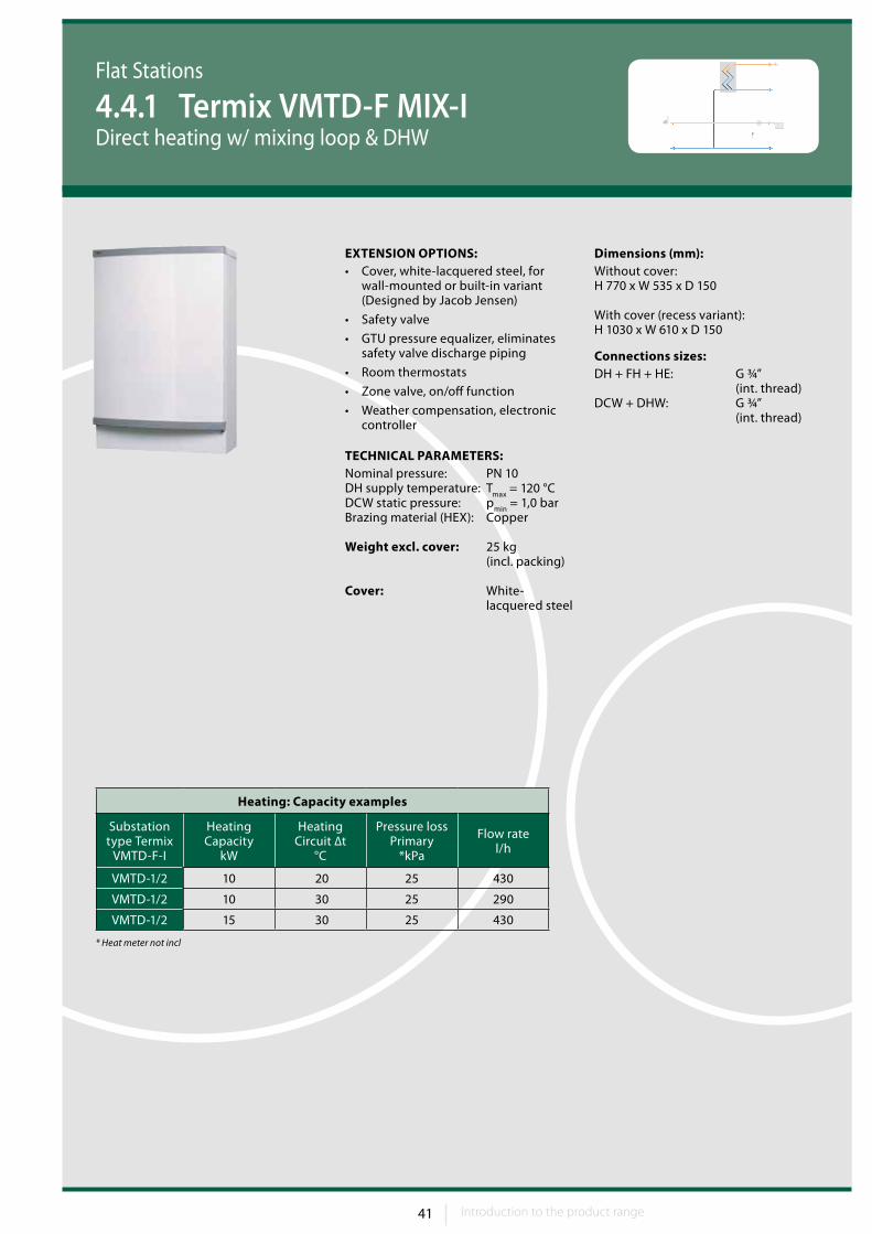
4.4.1 Termix VMTD-F MIX-IDirect heating w/ mixing loop & DHW
Dimensions (mm):Without cover:H 770 x W 535 x D 150
With cover (recess variant):H 1030 x W 610 x D 150
Connections sizes:DH + FH + HE: G ¾” (int. thread)DCW + DHW: G ¾” (int. thread)
EXTENSION OPTIONS:• Cover, white-lacquered steel, for
wall-mounted or built-in variant (Designed by Jacob Jensen)
• Safety valve
• GTU pressure equalizer, eliminates safety valve discharge piping
• Room thermostats
• Zone valve, on/off function
• Weather compensation, electronic controller
TECHNICAL PARAMETERS:Nominal pressure: PN 10DH supply temperature: T
max = 120 °C
DCW static pressure: pmin
= 1,0 barBrazing material (HEX): Copper
Weight excl. cover: 25 kg (incl. packing)
Cover: White- lacquered steel
Heating: Capacity examples
Substation type Termix
VMTD-F-I
Heating Capacity
kW
Heating Circuit ∆t
°C
Pressure lossPrimary
*kPa
Flow rate l/h
VMTD-1/2 10 20 25 430
VMTD-1/2 10 30 25 290
VMTD-1/2 15 30 25 430
* Heat meter not incl
42 Introduction to the product range42 43
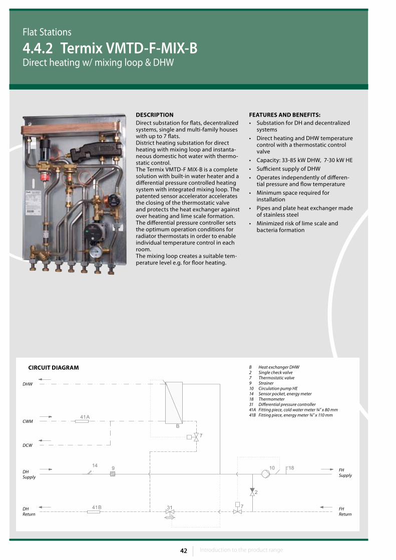
FEATuRES AND BENEFITS:• Substation for DH and decentralized
systems
• Direct heating and DHW temperature control with a thermostatic control valve
• Capacity: 33-85 kW DHW, 7-30 kW HE
• Sufficient supply of DHW
• Operates independently of differen-tial pressure and flow temperature
• Minimum space required for installation
• Pipes and plate heat exchanger made of stainless steel
• Minimized risk of lime scale and bacteria formation
CIRCuIT DIAGRAM
DCW
CWM
DHSupply
DHReturn
FHSupply
FHReturn
B Heat exchanger DHW 2 Single check valve7 Thermostatic valve9 Strainer10 Circulation pump HE14 Sensor pocket, energy meter18 Thermometer31 Differential pressure controller41A Fitting piece, cold water meter ¾” x 80 mm41B Fitting piece, energy meter ¾” x 110 mm
DHW
DESCRIPTIONDirect substation for flats, decentralized systems, single and multi-family houses with up to 7 flats.District heating substation for direct heating with mixing loop and instanta-neous domestic hot water with thermo-static control. The Termix VMTD-F MIX-B is a complete solution with built-in water heater and a differential pressure controlled heating system with integrated mixing loop. The patented sensor accelerator accelerates the closing of the thermostatic valve and protects the heat exchanger against over heating and lime scale formation.The differential pressure controller sets the optimum operation conditions for radiator thermostats in order to enable individual temperature control in each room. The mixing loop creates a suitable tem-perature level e.g. for floor heating.
Flat Stations
4.4.2 Termix VMTD-F-MIX-BDirect heating w/ mixing loop & DHW
Introduction to the product range 43 Introduction to the product range
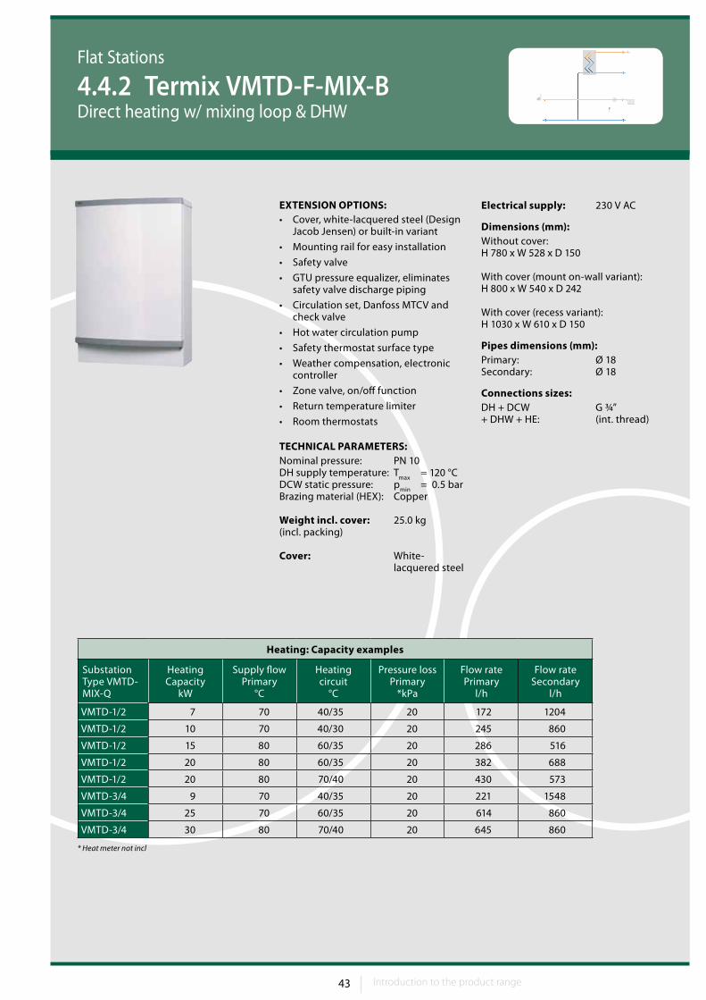
Electrical supply: 230 V AC
Dimensions (mm):Without cover:H 780 x W 528 x D 150
With cover (mount on-wall variant):H 800 x W 540 x D 242
With cover (recess variant):H 1030 x W 610 x D 150
Pipes dimensions (mm):Primary: Ø 18Secondary: Ø 18
Connections sizes:DH + DCW G ¾” + DHW + HE: (int. thread)
Flat Stations
4.4.2 Termix VMTD-F-MIX-BDirect heating w/ mixing loop & DHW
EXTENSION OPTIONS:• Cover, white-lacquered steel (Design
Jacob Jensen) or built-in variant
• Mounting rail for easy installation
• Safety valve
• GTU pressure equalizer, eliminates safety valve discharge piping
• Circulation set, Danfoss MTCV and check valve
• Hot water circulation pump
• Safety thermostat surface type
• Weather compensation, electronic controller
• Zone valve, on/off function
• Return temperature limiter
• Room thermostats
TECHNICAL PARAMETERS:Nominal pressure: PN 10DH supply temperature: T
max = 120 °C
DCW static pressure: pmin
= 0.5 barBrazing material (HEX): Copper
Weight incl. cover: 25.0 kg(incl. packing)
Cover: White- lacquered steel
Heating: Capacity examples
Substation Type VMTD-MIX-Q
Heating Capacity
kW
Supply flow Primary
°C
Heating circuit
°C
Pressure loss Primary
*kPa
Flow rate Primary
l/h
Flow rate Secondary
l/h
VMTD-1/2 7 70 40/35 20 172 1204
VMTD-1/2 10 70 40/30 20 245 860
VMTD-1/2 15 80 60/35 20 286 516
VMTD-1/2 20 80 60/35 20 382 688
VMTD-1/2 20 80 70/40 20 430 573
VMTD-3/4 9 70 40/35 20 221 1548
VMTD-3/4 25 70 60/35 20 614 860
VMTD-3/4 30 80 70/40 20 645 860
* Heat meter not incl
44 Introduction to the product range44 45
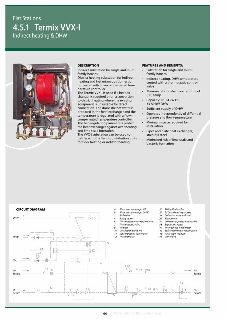
FEATuRES AND BENEFITS:• Substation for single and multi-
family houses
• Indirect heating, DHW temperature control with a thermostatic control valve
• Thermostatic or electronic control of (HE) temp.
• Capacity: 18-54 kW HE, 33-59 kW DHW
• Sufficient supply of DHW
• Operates independently of differntial pressure and flow temperature
• Minimum space required for installation
• Pipes and plate heat exchanger, stainless steel
• Minimized risk of lime scale and bacteria formation
CIRCuIT DIAGRAM
Circ.
DHW
DCW
DHSupply
DHReturn
HESupply
HEReturn
20 Filling/drain valve21 To be ordered separately24 Delivered loose with unit26 Manometer31 Differential pressure controller38 Expansion vessel41 Fitting piece, heat meter42 Safety valve/non-return valve48 Air escape, manual74 IHPT valve
A Plate heat exchanger HEB Plate heat exchanger DHW 1 Ball valve4 Safety valve6 Thermostatic/non-return valve7 Thermostatic valve9 Strainer10 Circulation pump HE14 Sensor pocket, heat meter18 Thermometer
DESCRIPTIONIndirect substation for single and multi-family houses.District heating substation for indirect heating and instantaneous domestic hot water with flow-compensated tem-perature controller. The Termix VVX-I is used if a heat ex-changer is required or on a conversion to district heating where the existing equipment is unsuitable for direct connection. The domestic hot water is prepared in the heat exchanger and the temperature is regulated with a flow-compensated temperature controller. The two regulating parameters protect the heat exchanger against over heating and lime scale formation.The VVX-I substation can be used to-gether with the Termix distribution units for floor heating or radiator heating.
Flat Stations
4.5.1 Termix VVX-IIndirect heating & DHW

Introduction to the product range 45 Introduction to the product range
Weight incl. cover: 29 kg(incl. packing)
Electrical supply: 230 V AC
Cover: White- lacquered steel
Dimensions (mm):Without cover:H 750 x W 505 x D 375
With cover:H 800 x W 540 x D 430
Pipes dimensions (mm):Primary: Ø 18Secondary: Ø 18
Connections sizes:DH + HE: G ¾” (int. thread)DCW + DHW: G ¾” (int. thread)
Flat Stations
4.5.1 Termix VVX-IIndirect heating & DHW
EXTENSION OPTIONS:• Cover, white-lacquered steel (Design
Jacob Jensen)
• Safety valve
• GTU pressure equalizer, eliminates safety valve discharge piping
• Booster pump (increases DH flow)
• Pipe insulation
• Mixing circuits for under floor heat-ing
• Floor heating manifold system
• Safety thermostat surface type
• Weather compensation, electronic controls
• Filling line, refill from DH for heating circuit
• Zone valve with actuator
TECHNICAL PARAMETERS:Nominal pressure: PN 10*DH supply temperature: T
max = 120 °C
DCW static pressure: pmin
= 1.0 barBrazing material (HEX): Copper
* PN 16 versions are available on request
Heating: Capacity examples
Substation type Termix VVX-I
Heating Capacity
kW
Supply flow primary
°C
Heating circuit
°C
Pressure loss Primary
*kPa
Pressure loss Secondary
*kPa
Flow rate Primary
l/h
Flow rate Secondary
l/h
VVX x-1
18 70 60/35 25 20 442 650
20 80 70/40 25 20 430 603
24 90 70/40 25 20 476 724
VVX x-2
30 70 60/35 35 20 737 1084
34 80 70/40 35 20 731 1025
40 90 70/40 35 20 783 1206
VVX x-3
45 70 60/35 45 20 1106 1629
50 80 70/40 45 20 1075 1509
54 90 70/40 45 20 980 1629
* Heat meter not incl
46 Introduction to the product range46 47
CIRCuIT DIAGRAM
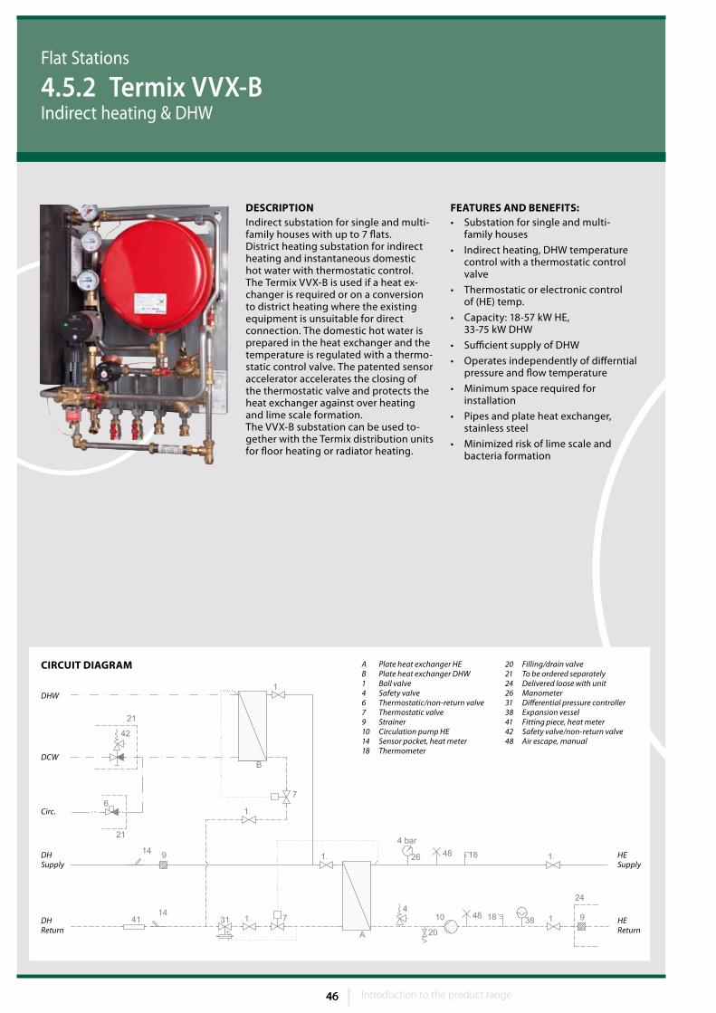
FEATuRES AND BENEFITS:• Substation for single and multi-
family houses
• Indirect heating, DHW temperature control with a thermostatic control valve
• Thermostatic or electronic control of (HE) temp.
• Capacity: 18-57 kW HE, 33-75 kW DHW
• Sufficient supply of DHW
• Operates independently of differntial pressure and flow temperature
• Minimum space required for installation
• Pipes and plate heat exchanger, stainless steel
• Minimized risk of lime scale and bacteria formation
Circ.
DHW
DCW
DHSupply
DHReturn
HESupply
HEReturn
20 Filling/drain valve21 To be ordered separately24 Delivered loose with unit26 Manometer31 Differential pressure controller38 Expansion vessel41 Fitting piece, heat meter42 Safety valve/non-return valve48 Air escape, manual
A Plate heat exchanger HEB Plate heat exchanger DHW 1 Ball valve4 Safety valve6 Thermostatic/non-return valve7 Thermostatic valve9 Strainer10 Circulation pump HE14 Sensor pocket, heat meter18 Thermometer
DESCRIPTIONIndirect substation for single and multi-family houses with up to 7 flats.District heating substation for indirect heating and instantaneous domestic hot water with thermostatic control. The Termix VVX-B is used if a heat ex-changer is required or on a conversion to district heating where the existing equipment is unsuitable for direct connection. The domestic hot water is prepared in the heat exchanger and the temperature is regulated with a thermo-static control valve. The patented sensor accelerator accelerates the closing of the thermostatic valve and protects the heat exchanger against over heating and lime scale formation.The VVX-B substation can be used to-gether with the Termix distribution units for floor heating or radiator heating.
Flat Stations
4.5.2 Termix VVX-BIndirect heating & DHW
Introduction to the product range 47 Introduction to the product range
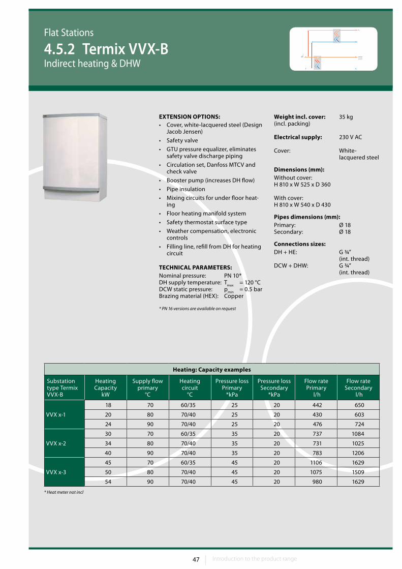
Weight incl. cover: 35 kg(incl. packing)
Electrical supply: 230 V AC
Cover: White- lacquered steel
Dimensions (mm):Without cover:H 810 x W 525 x D 360
With cover:H 810 x W 540 x D 430
Pipes dimensions (mm):Primary: Ø 18Secondary: Ø 18
Connections sizes:DH + HE: G ¾” (int. thread)DCW + DHW: G ¾” (int. thread)
Flat Stations
4.5.2 Termix VVX-BIndirect heating & DHW
EXTENSION OPTIONS:• Cover, white-lacquered steel (Design
Jacob Jensen)
• Safety valve
• GTU pressure equalizer, eliminates safety valve discharge piping
• Circulation set, Danfoss MTCV and check valve
• Booster pump (increases DH flow)
• Pipe insulation
• Mixing circuits for under floor heat-ing
• Floor heating manifold system
• Safety thermostat surface type
• Weather compensation, electronic controls
• Filling line, refill from DH for heating circuit
TECHNICAL PARAMETERS:Nominal pressure: PN 10*DH supply temperature: T
max = 120 °C
DCW static pressure: pmin
= 0.5 barBrazing material (HEX): Copper
* PN 16 versions are available on request
Heating: Capacity examples
Substation type Termix VVX-B
Heating Capacity
kW
Supply flow primary
°C
Heating circuit
°C
Pressure loss Primary
*kPa
Pressure loss Secondary
*kPa
Flow rate Primary
l/h
Flow rate Secondary
l/h
VVX x-1
18 70 60/35 25 20 442 650
20 80 70/40 25 20 430 603
24 90 70/40 25 20 476 724
VVX x-2
30 70 60/35 35 20 737 1084
34 80 70/40 35 20 731 1025
40 90 70/40 35 20 783 1206
VVX x-3
45 70 60/35 45 20 1106 1629
50 80 70/40 45 20 1075 1509
54 90 70/40 45 20 980 1629
* Heat meter not incl
48 Introduction to the product range48 49
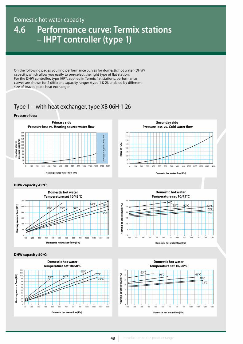
Domestic hot water capacity
4.6 Performance curve: Termix stations – IHPT controller (type 1)
Pressure loss:
DHW capacity 45ºC:
DHW capacity 50ºC:
Type 1 – with heat exchanger, type XB 06H-1 26
On the following pages you find performance curves for domestic hot water (DHW) capacity, which allow you easily to pre-select the right type of flat station.For the DHW controller, type IHPT, applied in Termix flat stations, performance curves are shown for 2 different capacity ranges (type 1 & 2), enabled by different size of brazed plate heat exchanger.
Introduction to the product range 49 Introduction to the product range
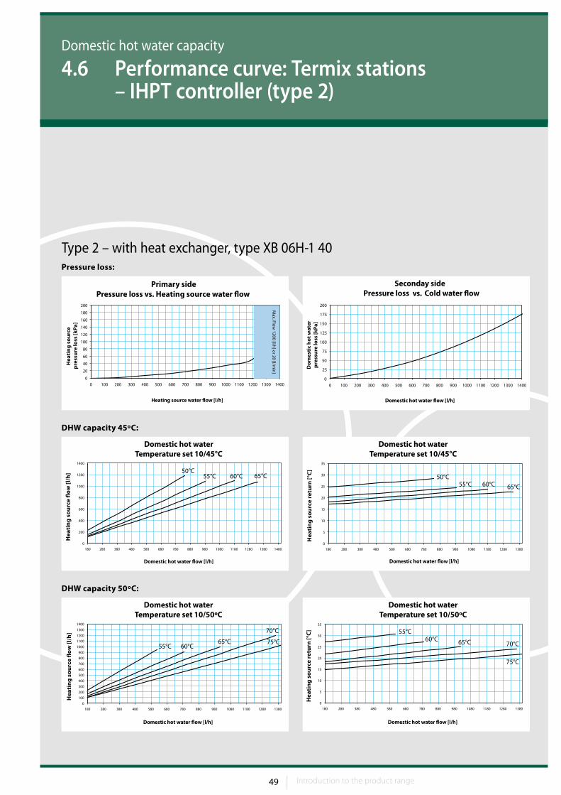
Domestic hot water capacity
4.6 Performance curve: Termix stations – IHPT controller (type 2)
Pressure loss:
DHW capacity 45ºC:
DHW capacity 50ºC:
Type 2 – with heat exchanger, type XB 06H-1 40
50 Introduction to the product range50 51
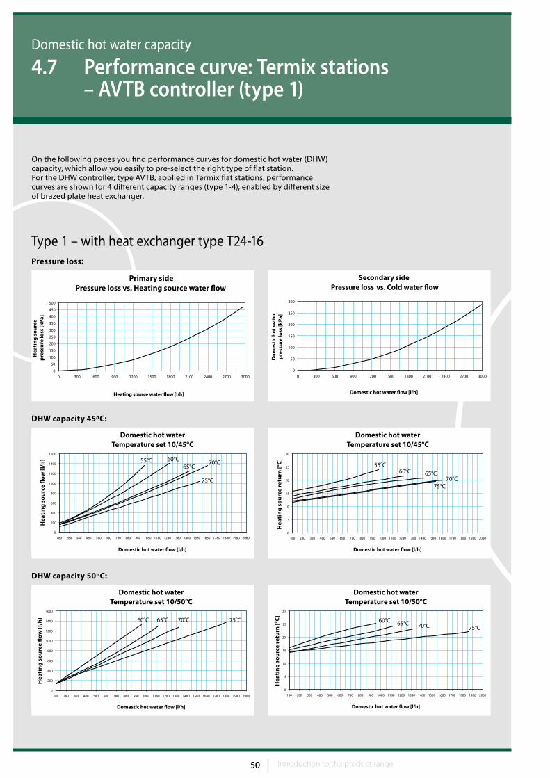
Domestic hot water capacity
4.7 Performance curve: Termix stations – AVTB controller (type 1)
Pressure loss:
DHW capacity 45ºC:
DHW capacity 50ºC:
On the following pages you find performance curves for domestic hot water (DHW) capacity, which allow you easily to pre-select the right type of flat station.For the DHW controller, type AVTB, applied in Termix flat stations, performance curves are shown for 4 different capacity ranges (type 1-4), enabled by different size of brazed plate heat exchanger.
Type 1 – with heat exchanger type T24-16
Introduction to the product range 51 Introduction to the product range
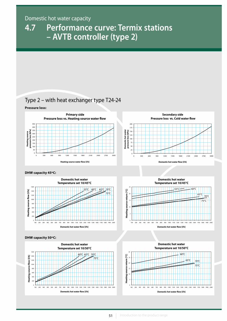
Domestic hot water capacity
4.7 Performance curve: Termix stations – AVTB controller (type 2)
Pressure loss:
DHW capacity 45ºC:
DHW capacity 50ºC:
Type 2 – with heat exchanger type T24-24
52 Introduction to the product range52 53
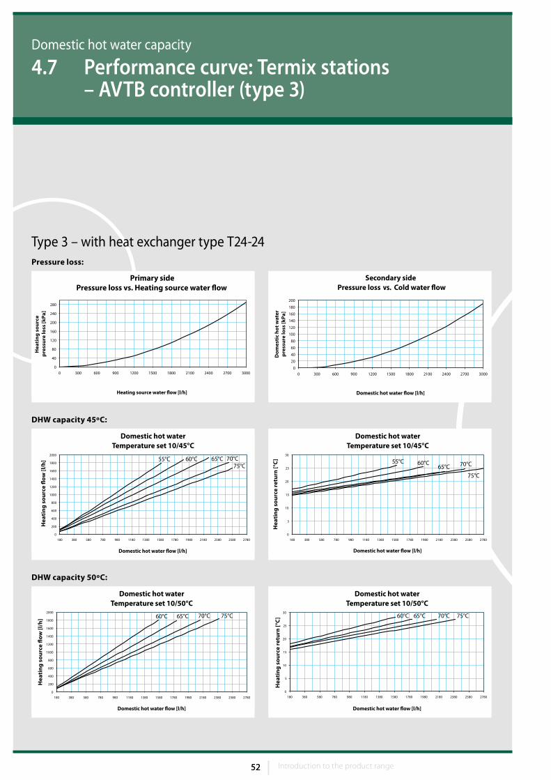
Domestic hot water capacity
4.7 Performance curve: Termix stations – AVTB controller (type 3)
Pressure loss:
DHW capacity 45ºC:
DHW capacity 50ºC:
Type 3 – with heat exchanger type T24-24
Introduction to the product range 53 Introduction to the product range
Domestic hot water capacity
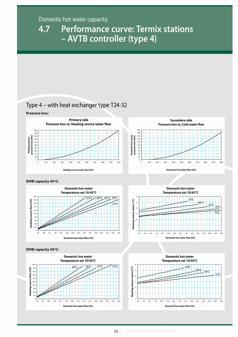
4.7 Performance curve: Termix stations – AVTB controller (type 4)
Pressure loss:
DHW capacity 45ºC:
DHW capacity 50ºC:
Type 4 – with heat exchanger type T24-32

54 Introduction to the product range54
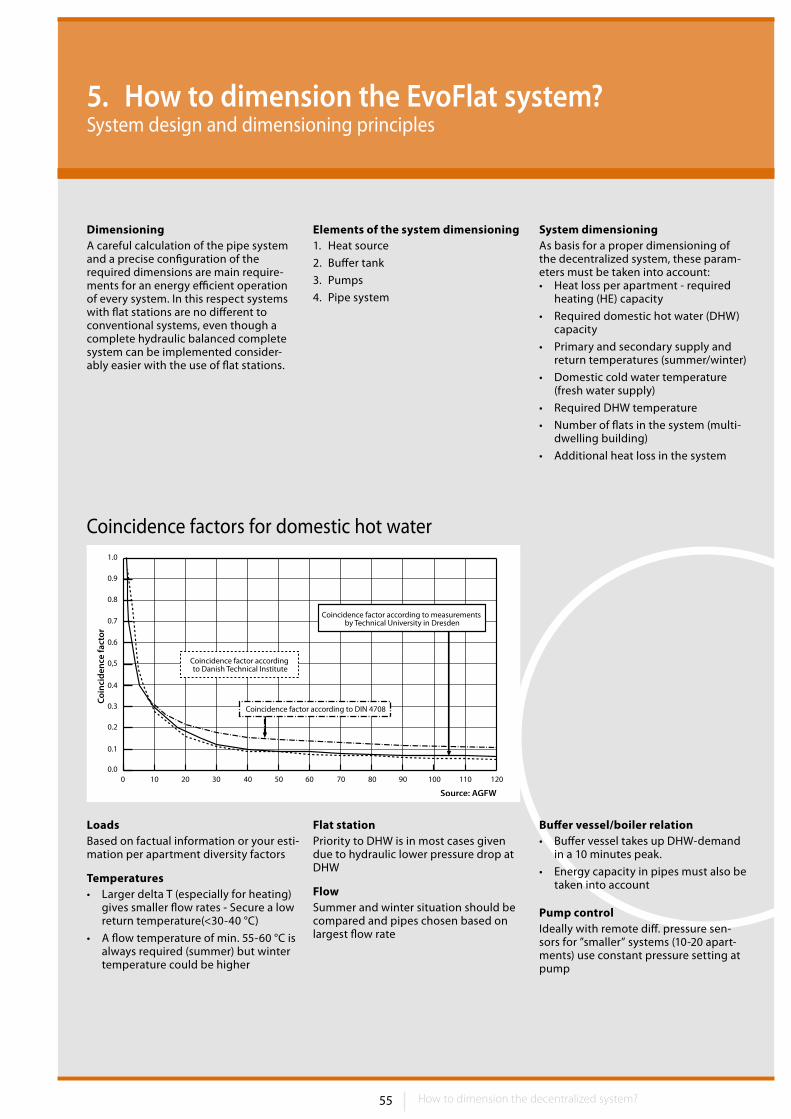
55 How to dimension the decentralized system?
5. How to dimension the EvoFlat system?System design and dimensioning principles
DimensioningA careful calculation of the pipe system and a precise configuration of the required dimensions are main require-ments for an energy efficient operation of every system. In this respect systems with flat stations are no different to conventional systems, even though a complete hydraulic balanced complete system can be implemented consider-ably easier with the use of flat stations.
Elements of the system dimensioning1. Heat source
2. Buffer tank
3. Pumps
4. Pipe system
System dimensioningAs basis for a proper dimensioning of the decentralized system, these param-eters must be taken into account: • Heat loss per apartment - required
heating (HE) capacity
• Required domestic hot water (DHW) capacity
• Primary and secondary supply and return temperatures (summer/winter)
• Domestic cold water temperature (fresh water supply)
• Required DHW temperature
• Number of flats in the system (multi-dwelling building)
• Additional heat loss in the system
LoadsBased on factual information or your esti-mation per apartment diversity factors
Temperatures• Larger delta T (especially for heating)
gives smaller flow rates - Secure a low return temperature(<30-40 °C)
• A flow temperature of min. 55-60 °C is always required (summer) but winter temperature could be higher
Flat stationPriority to DHW is in most cases given due to hydraulic lower pressure drop at DHW
FlowSummer and winter situation should be compared and pipes chosen based on largest flow rate
Buffer vessel/boiler relation• Buffer vessel takes up DHW-demand
in a 10 minutes peak.
• Energy capacity in pipes must also be taken into account
Pump controlIdeally with remote diff. pressure sen-sors for ”smaller” systems (10-20 apart-ments) use constant pressure setting at pump
0.00 10 20 30 40 50 60 70 80 90 100 110 120
0.1
0.2
0.3
0.4
0.6
0.7
0.8
0.9
0,5
1.0
Coincidence factors for domestic hot water
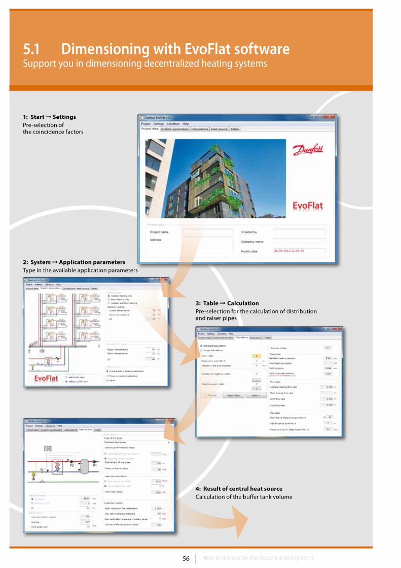
56 57How to dimension the decentralized system?
5.1 Dimensioning with EvoFlat softwareSupport you in dimensioning decentralized heating systems
1: Start ➞ SettingsPre-selection of the coincidence factors
3: Table ➞ CalculationPre-selection for the calculation of distribution and raiser pipes
4: Result of central heat sourceCalculation of the buffer tank volume
2: System ➞ Application parametersType in the available application parameters
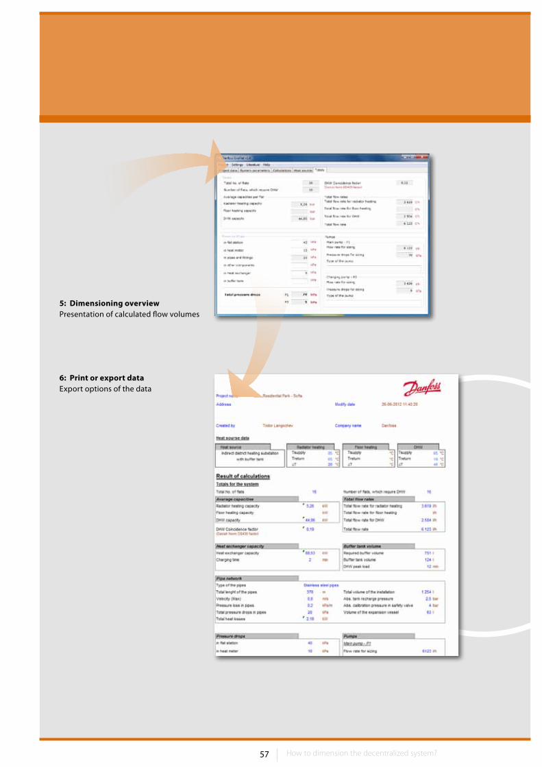
57How to dimension the decentralized system? How to dimension the decentralized system?
5: Dimensioning overviewPresentation of calculated flow volumes
6: Print or export data Export options of the data
58 How to dimension the decentralized system?
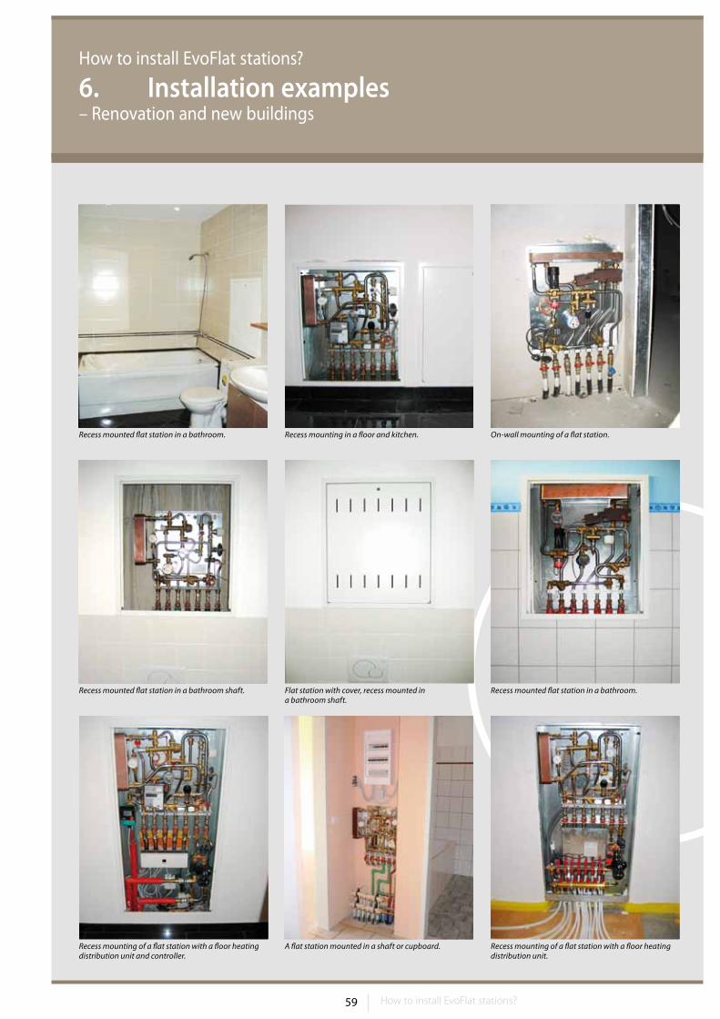
59 How to install EvoFlat stations?
How to install EvoFlat stations?
6. Installation examples – Renovation and new buildings
Recess mounted flat station in a bathroom. Recess mounting in a floor and kitchen.
Recess mounting of a flat station with a floor heating distribution unit and controller.
Recess mounted flat station in a bathroom shaft. Recess mounted flat station in a bathroom.Flat station with cover, recess mounted in a bathroom shaft.
A flat station mounted in a shaft or cupboard.
On-wall mounting of a flat station.
Recess mounting of a flat station with a floor heating distribution unit.
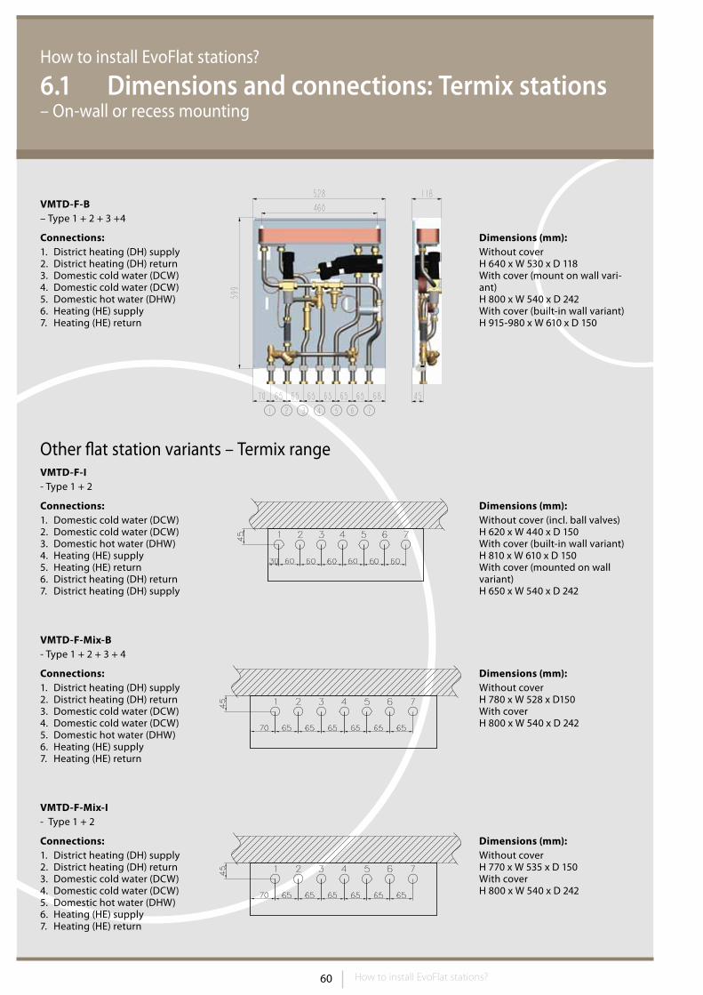
60 How to install EvoFlat stations?
How to install EvoFlat stations?
6.1 Dimensions and connections: Termix stations– On-wall or recess mounting
VMTD-F-B– Type 1 + 2 + 3 +4
Connections:1. District heating (DH) supply2. District heating (DH) return3. Domestic cold water (DCW)4. Domestic cold water (DCW)5. Domestic hot water (DHW)6. Heating (HE) supply7. Heating (HE) return
Other flat station variants – Termix rangeVMTD-F-I- Type 1 + 2
VMTD-F-Mix-B- Type 1 + 2 + 3 + 4
Connections:1. Domestic cold water (DCW)2. Domestic cold water (DCW)3. Domestic hot water (DHW)4. Heating (HE) supply5. Heating (HE) return6. District heating (DH) return7. District heating (DH) supply
Dimensions (mm):Without cover (incl. ball valves)H 620 x W 440 x D 150With cover (built-in wall variant)H 810 x W 610 x D 150With cover (mounted on wall variant)H 650 x W 540 x D 242
Connections:1. District heating (DH) supply2. District heating (DH) return3. Domestic cold water (DCW)4. Domestic cold water (DCW)5. Domestic hot water (DHW)6. Heating (HE) supply7. Heating (HE) return
Dimensions (mm):Without coverH 780 x W 528 x D150With coverH 800 x W 540 x D 242
Connections:1. District heating (DH) supply2. District heating (DH) return3. Domestic cold water (DCW)4. Domestic cold water (DCW)5. Domestic hot water (DHW)6. Heating (HE) supply7. Heating (HE) return
Dimensions (mm):Without coverH 770 x W 535 x D 150With coverH 800 x W 540 x D 242
VMTD-F-Mix-I- Type 1 + 2
Dimensions (mm):Without coverH 640 x W 530 x D 118With cover (mount on wall vari-ant)H 800 x W 540 x D 242With cover (built-in wall variant) H 915-980 x W 610 x D 150
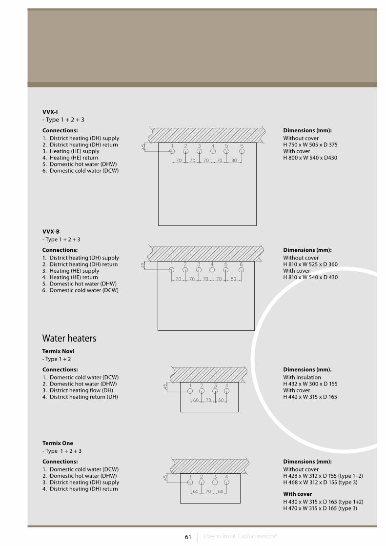
61 How to install EvoFlat stations?
Water heaters
VVX-I- Type 1 + 2 + 3
Connections:1. District heating (DH) supply2. District heating (DH) return3. Heating (HE) supply4. Heating (HE) return5. Domestic hot water (DHW)6. Domestic cold water (DCW)
Dimensions (mm):Without coverH 750 x W 505 x D 375With coverH 800 x W 540 x D430
VVX-B- Type 1 + 2 + 3
Connections:1. District heating (DH) supply2. District heating (DH) return3. Heating (HE) supply4. Heating (HE) return5. Domestic hot water (DHW)6. Domestic cold water (DCW)
Dimensions (mm):Without coverH 810 x W 525 x D 360With coverH 810 x W 540 x D 430
Termix Novi- Type 1 + 2
Connections:1. Domestic cold water (DCW)2. Domestic hot water (DHW)3. District heating flow (DH)4. District heating return (DH)
Dimensions (mm).With insulationH 432 x W 300 x D 155With coverH 442 x W 315 x D 165
Termix One- Type 1 + 2 + 3
Connections:1. Domestic cold water (DCW)2. Domestic hot water (DHW)3. District heating (DH) supply4. District heating (DH) return
Dimensions (mm):Without coverH 428 x W 312 x D 155 (type 1+2)H 468 x W 312 x D 155 (type 3)
With coverH 430 x W 315 x D 165 (type 1+2)H 470 x W 315 x D 165 (type 3)
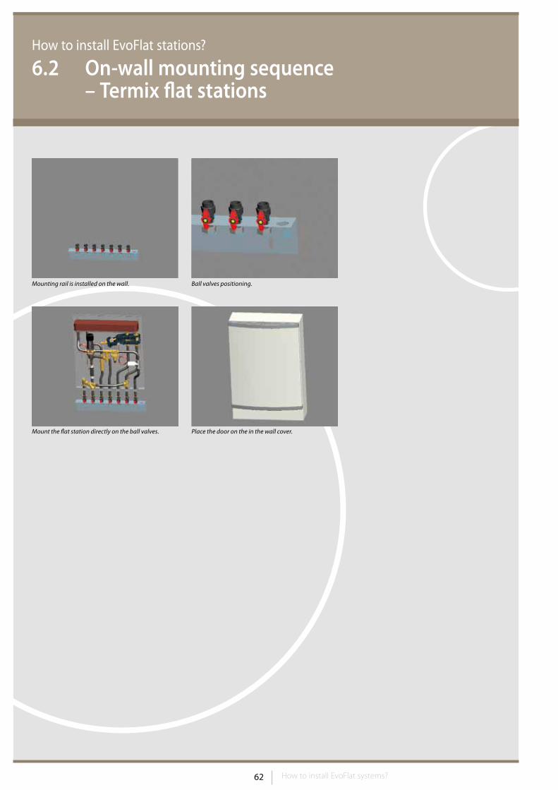
62 How to install EvoFlat systems?
How to install EvoFlat stations?
6.2 On-wall mounting sequence – Termix flat stations
Mounting rail is installed on the wall.
Mount the flat station directly on the ball valves.
Ball valves positioning.
Place the door on the in the wall cover.
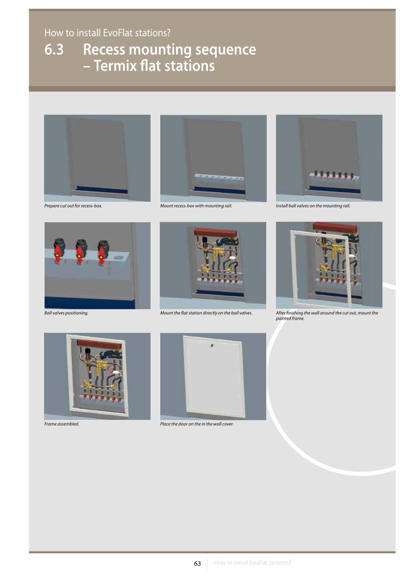
63 How to install EvoFlat systems?
Prepare cut out for recess-box.
Frame assembled.
Ball valves positioning.
Mount recess-box with mounting rail. Install ball valves on the mounting rail.
Place the door on the in the wall cover.
Mount the flat station directly on the ball valves. After finishing the wall around the cut out, mount the painted frame.
How to install EvoFlat stations?
6.3 Recess mounting sequence – Termix flat stations
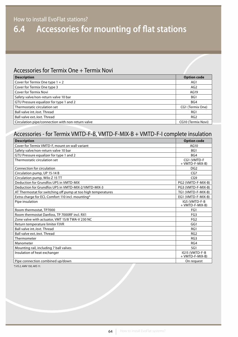
64 How to install EvoFlat systems?
How to install EvoFlat stations?
6.4 Accessories for mounting of flat stations
Description Option codeCover for Termix One type 1 + 2 AG1Cover for Termix One type 3 AG2Cover for Termix Novi AG19Safety valve/non-return valve 10 bar BG1GTU Pressure equalizer for type 1 and 2 BG4Thermostatic circulation set CG1 (Termix One)Ball valve int./ext. Thread RG1Ball valve ext./ext. Thread RG2Circulation pipe/connection with non-return valve CG10 (Termix Novi)
Description Option codeCover for Termix VMTD-F, mount on wall variant AG10Safety valve/non-return valve 10 bar BG1GTU Pressure equalizer for type 1 and 2 BG4Thermostatic circulation set CG1 (VMTD-F
+ VMTD-F-MIX-B)Connection for circulation DG2Circulation pump, UP 15-14 B CG7Circulation pump, Wilo Z 15 TT CG9Deduction for Grundfos UPS in VMTD-MIX PG2 (VMTD-F-MIX-B)Deduction for Grundfos UPS in VMTD-MIX-2/VMTD-MIX-3 PG3 (VMTD-F-MIX-B)AT Thermostat for switching off pump at too high temperatures TG1 (VMTD-F-MIX-B)Extra charge for ECL Comfort 110 incl. mounting* EG1 (VMTD-F-MIX-B)Pipe insulation IG5 (VMTD-F-B
+ VMTD-F-MIX-B)Room thermostat, TP7000 FG1Room thermostat Danfoss, TP 7000RF incl. RX1 FG3Zone valve with actuator, VMT 15/8 TWA-V 230 NC FG2Return temperature limiter FJVR GG1Ball valve int./ext. Thread RG1Ball valve ext./ext. Thread RG2Thermometer RG3Manometer RG4Mounting rail, including 7 ball valves SG1Insulation of heat exchanger IG15 (VMTD-F-B
+ VMTD-F-MIX-B)Pipe connection combined up/down On request
*) VS 2, AMV 150, AKS 11.
Accessories for Termix One + Termix Novi
Accessories - for Termix VMTD-F-B, VMTD-F-MIX-B + VMTD-F-I complete insulation
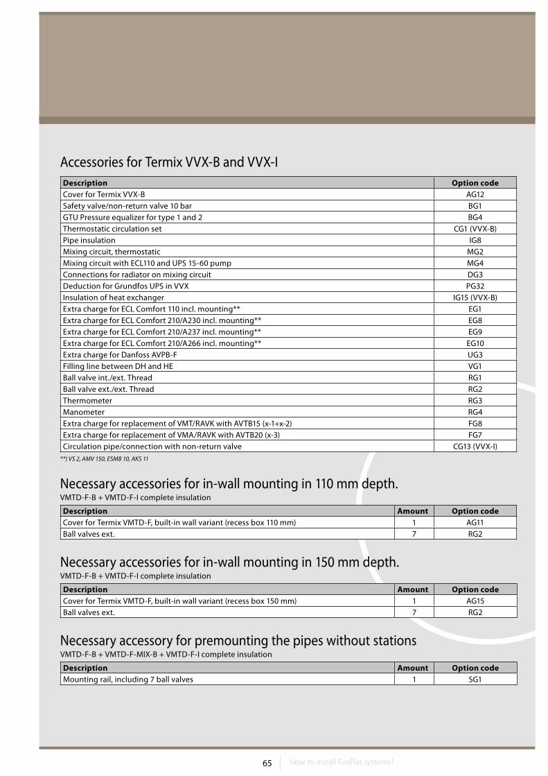
65 How to install EvoFlat systems?
Description Amount Option codeCover for Termix VMTD-F, built-in wall variant (recess box 110 mm) 1 AG11Ball valves ext. 7 RG2
Description Amount Option codeCover for Termix VMTD-F, built-in wall variant (recess box 150 mm) 1 AG15Ball valves ext. 7 RG2
Description Amount Option codeMounting rail, including 7 ball valves 1 SG1
Description Option codeCover for Termix VVX-B AG12Safety valve/non-return valve 10 bar BG1GTU Pressure equalizer for type 1 and 2 BG4Thermostatic circulation set CG1 (VVX-B)Pipe insulation IG8Mixing circuit, thermostatic MG2Mixing circuit with ECL110 and UPS 15-60 pump MG4Connections for radiator on mixing circuit DG3Deduction for Grundfos UPS in VVX PG32Insulation of heat exchanger IG15 (VVX-B)Extra charge for ECL Comfort 110 incl. mounting** EG1Extra charge for ECL Comfort 210/A230 incl. mounting** EG8Extra charge for ECL Comfort 210/A237 incl. mounting** EG9Extra charge for ECL Comfort 210/A266 incl. mounting** EG10Extra charge for Danfoss AVPB-F UG3Filling line between DH and HE VG1Ball valve int./ext. Thread RG1Ball valve ext./ext. Thread RG2Thermometer RG3Manometer RG4Extra charge for replacement of VMT/RAVK with AVTB15 (x-1+x-2) FG8Extra charge for replacement of VMA/RAVK with AVTB20 (x-3) FG7Circulation pipe/connection with non-return valve CG13 (VVX-I)
**) VS 2, AMV 150, ESMB 10, AKS 11
Necessary accessories for in-wall mounting in 110 mm depth.VMTD-F-B + VMTD-F-I complete insulation
Necessary accessories for in-wall mounting in 150 mm depth.VMTD-F-B + VMTD-F-I complete insulation
Necessary accessory for premounting the pipes without stationsVMTD-F-B + VMTD-F-MIX-B + VMTD-F-I complete insulation
Accessories for Termix VVX-B and VVX-I
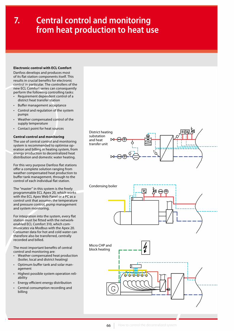
66 67
District heating substation and heat transfer unit
Condensing boiler
Micro CHP and block heating
Solar controller
Optional
How to control the decentralized system
7. Central control and monitoring from heat production to heat use
Electronic control with ECL ComfortDanfoss develops and produces most of its flat station components itself. This results in crucial benefits for electronic control in particular. The controllers of the new ECL Comfort series can consequently perform the following controlling tasks:• Requirement dependent control of a
district heat transfer station
• Buffer management acceptance
• Control and regulation of the system pumps
• Weather compensated control of the supply temperature
• Contact point for heat sources
Central control and monitoringThe use of central control and monitoring system is recommended to optimise op-eration and billing in heating system, from energy production to decentralized heat distribution and domestic water heating.
For this very purpose Danfoss flat stations offer a complete solution ranging from weather compensated heat production to buffer tank management, through to the control of each individual flat station.
The “master” in this system is the freely programmable ECL Apex 20, which works with the ECL Apex Web Panel or a PC as a control unit that assumes the temperature and pressure control, pump management and system monitoring.
For integration into the system, every flat station must be fitted with the network-enabled ECL Comfort 310, which com-municates via Modbus with the Apex 20. Consumer data for hot and cold water can therefore also be transferred, centrally recorded and billed.
The most important benefits of central control and monitoring are:• Weather compensated heat production
(boiler, local and district heating)
• Optimum buffer tank and solar man-agement
• Highest possible system operation reli-ability
• Energy efficient energy distribution
• Central consumption recording and billing
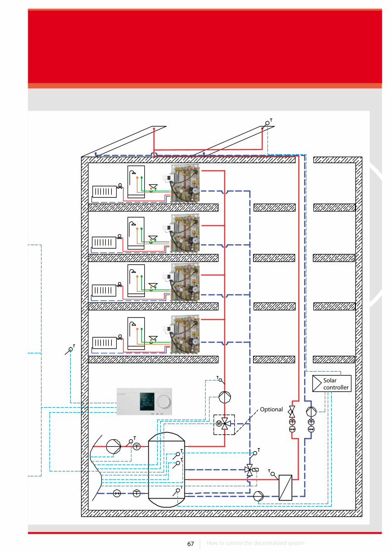
67
District heating substation and heat transfer unit
Condensing boiler
Micro CHP and block heating
Solar controller
Optional
How to control the decentralized system How to control the decentralized system
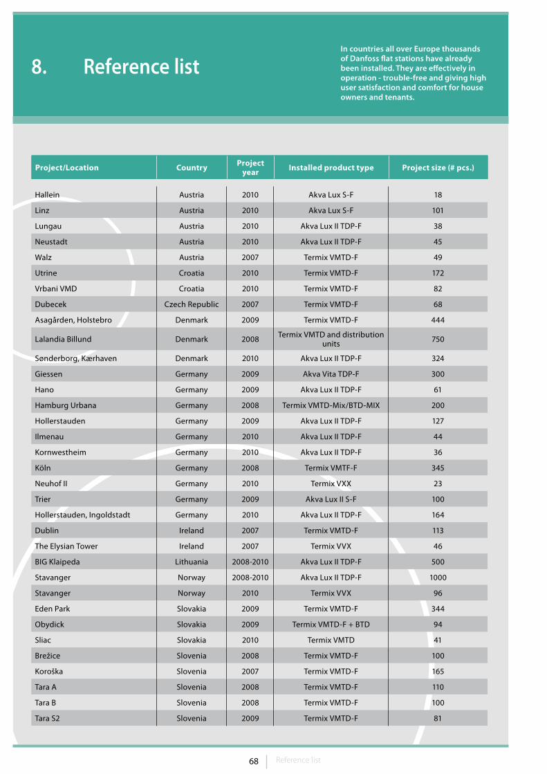
68 69Reference list
8. Reference listIn countries all over Europe thousands of Danfoss flat stations have already been installed. They are effectively in operation - trouble-free and giving high user satisfaction and comfort for house owners and tenants.
Project/Location Country Project year Installed product type Project size (# pcs.)
Hallein Austria 2010 Akva Lux S-F 18
Linz Austria 2010 Akva Lux S-F 101
Lungau Austria 2010 Akva Lux II TDP-F 38
Neustadt Austria 2010 Akva Lux II TDP-F 45
Walz Austria 2007 Termix VMTD-F 49
Utrine Croatia 2010 Termix VMTD-F 172
Vrbani VMD Croatia 2010 Termix VMTD-F 82
Dubecek Czech Republic 2007 Termix VMTD-F 68
Asagården, Holstebro Denmark 2009 Termix VMTD-F 444
Lalandia Billund Denmark 2008 Termix VMTD and distribution units 750
Sønderborg, Kærhaven Denmark 2010 Akva Lux II TDP-F 324
Giessen Germany 2009 Akva Vita TDP-F 300
Hano Germany 2009 Akva Lux II TDP-F 61
Hamburg Urbana Germany 2008 Termix VMTD-Mix/BTD-MIX 200
Hollerstauden Germany 2009 Akva Lux II TDP-F 127
Ilmenau Germany 2010 Akva Lux II TDP-F 44
Kornwestheim Germany 2010 Akva Lux II TDP-F 36
Köln Germany 2008 Termix VMTF-F 345
Neuhof II Germany 2010 Termix VXX 23
Trier Germany 2009 Akva Lux II S-F 100
Hollerstauden, Ingoldstadt Germany 2010 Akva Lux II TDP-F 164
Dublin Ireland 2007 Termix VMTD-F 113
The Elysian Tower Ireland 2007 Termix VVX 46
BIG Klaipeda Lithuania 2008-2010 Akva Lux II TDP-F 500
Stavanger Norway 2008-2010 Akva Lux II TDP-F 1000
Stavanger Norway 2010 Termix VVX 96
Eden Park Slovakia 2009 Termix VMTD-F 344
Obydick Slovakia 2009 Termix VMTD-F + BTD 94
Sliac Slovakia 2010 Termix VMTD 41
Brežice Slovenia 2008 Termix VMTD-F 100
Koroška Slovenia 2007 Termix VMTD-F 165
Tara A Slovenia 2008 Termix VMTD-F 110
Tara B Slovenia 2008 Termix VMTD-F 100
Tara S2 Slovenia 2009 Termix VMTD-F 81
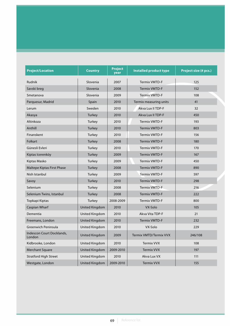
69Reference list Reference list
Project/Location Country Project year Installed product type Project size (# pcs.)
Rudnik Slovenia 2007 Termix VMTD-F 125
Savski breg Slovenia 2008 Termix VMTD-F 152
Smetanova Slovenia 2009 Termix VMTD-F 108
Parquesur, Madrid Spain 2010 Termix measuring units 41
Lerum Sweden 2010 Akva Lux II TDP-F 32
Akasya Turkey 2010 Akva Lux II TDP-F 450
Altinkoza Turkey 2010 Termix VMTD-F 193
Anthill Turkey 2010 Termix VMTD-F 803
Finanskent Turkey 2010 Termix VMTD-F 156
Folkart Turkey 2008 Termix VMTD-F 180
Günesli Evleri Turkey 2010 Termix VMTD-F 170
Kiptas Icerenköy Turkey 2009 Termix VMTD-F 167
Kiptas Masko Turkey 2009 Termix VMTD-F 450
Maltepe Kiptas First Phase Turkey 2008 Termix VMTD-F 890
Nish Istanbul Turkey 2009 Termix VMTD-F 597
Savoy Turkey 2010 Termix VMTD-F 298
Selenium Turkey 2008 Termix VMTD-F 216
Selenium Twins, Istanbul Turkey 2008 Termix VMTD-F 222
Topkapi Kiptas Turkey 2008-2009 Termix VMTD-F 800
Caspian Wharf United Kingdom 2010 VX-Solo 105
Dementia United Kingdom 2010 Akva Vita TDP-F 21
Freemans, London United Kingdom 2010 Termix VMTD-F 232
Greenwich Peninsula United Kingdom 2010 VX-Solo 229
Indescon Court Docklands, London United Kingdom 2009 Termix VMTD/Termix VVX 246/108
Kidbrooke, London United Kingdom 2010 Termix VVX 108
Merchant Square United Kingdom 2009-2010 Termix VVX 197
Stratford High Street United Kingdom 2010 Akva Lux VX 111
Westgate, London United Kingdom 2009-2010 Termix VVX 155
70 71FAQ
9. FAQ
1. Wet rooms set upThe combining of wet rooms (bathroom, toilet and kitchen) within an apartment can not only save on costs with less construction and installation materials – financial benefits, such as higher rental income or appropriation, can also be generated with greater utility space.
A distance of 6 meters between the flat station and the furthest consump-tion point should not be exceeded to rule out delay times when turning on hot water. If more than that, circulation pump should be added to maintain the end user comfort.
2. Noise and fire preventionThe applicable noise and fire prevention regulations must be concerned during flat station in wall installation.
The flat station should be installed in or-der to preserve fire prevention sections. During design must be ensured that applicable regulations are complied and additional measures are used to ensure that neither noise nor fire prevention are impaired.
3. Heat insulationContinuous and high quality insulation on hot pipelines is extremely important. This applies in particular to the distribu-tion set up on systems with flat stations. As these pipes are in operation around the clock the entire year long, solid insulation without gaps is indispensa-ble. Depending on the local regulations, a minimum insulation of 2/3 of the pipe diameter, but at least an insulation thickness of 30 mm, must be provided.
Insulation on the fittings at the distribu-tion pipes is also ideal, as higher losses can also occur because of the turbulent flows caused by the optimum heat transfers. The use of factory manufac-tured insulating shells, offered by many manufacturers, is ideal for these kinds of valves. With manually produced insulating shells you must ensure that, in addition to the shell‘s insulation thickness, they also close tightly and no convection occurs in the gaps.
4. Thermosiphon with buffer connection
Instead of fault prone non return valves, the connections of the heat exchanger‘s load lines and the solar system on the buffer tank should be provided with a thermo siphon, whereby the siphon height should correspond with 10 times the pipe diameter.
5. Inflow speed with buffer tankAll supply pipes connected to a buffer tank should be configured for a maximum inflow speed of 0.1 m/s; this prevents turbulences in the buffer tank and mixing of the different temperature layers.
6. Temperature measurement in the buffer tank
When selecting the buffer tank you must ensure measurement connections (as immersion sensors) to measure the available water temperatures.
The use of a heat conduction paste is recommended when installing the temperature sensor for improved heat conductivity.
7. Radiators in general areasThe complete implementation of hydronic concept must not be forgot-ten when heating general areas (e.g. corridors, laundry room, drying room, hobby room, etc.). This means:• Use of a differential pressure control-
ler in the radiator connection pipe
• Radiator valve sets presetting
• Use of a return temperature limiter
A flat station is also a good solution if hot water is required in a general area (e.g. laundry room).
8. Rooms with more than one radiator
With radiator systems with flat stations, all radiators should be equipped with thermostatic valves. All radiator thermo-stats within a room should be set to the same value to ensure a constant room temperature.
Fluctuating room temperature could be prevented by using high quality radiator thermostats.
Some exceptions are radiators in refer-ence rooms which, in combination with a room thermostat and a zone valve, are responsible for the heat supply for the entire apartment.
9. Connecting pressure measurement pipes
If a manometer or a measurement pipe is connected for pressure measuring, this connection should be made, if pos-sible, on vertical pipelines.
If the pressure measurement can only be made on a horizontal pipe because of structural conditions, the connection must be made horizontally in the centre of the pipe.
If these guidelines are not observed with the arrangement of the pres-sure measurement pipes, trapped air (connection above) or dirt build ups (connection below) can cause erroneous measurements.
Commissioning of flat stationsAll flat stations must be submitted to commissioning after the whole system is thoroughly rinsed. This should be documented as a test log (per unit). Danfoss provides appropriate commis-sioning for Danfoss flat stations.
Advises to design and installation

71FAQ Notes
Notes

Danfoss can accept no responsibility for possible errors in catalogues, brochures and other printed material. Danfoss reserves the right to alter its products without notice. This also applies to products already on order provided that such alterations can be made without subsequential changes being necessary in speci�cations already agreed. All trademarks in this material are property of the respective companies. Danfoss and the Danfoss logotype are trademarks of Danfoss A/S. All rights reserved.
Danfoss A/S · DK-6430 Nordborg · Denmark · Tel.: +45 74 88 22 22 · Fax: +45 74 49 03 95E-mail: [email protected] · www.districtenergy.danfoss.com
VGHEB102 26691 · www.factorx.dk
Most of it we make ourselvesAll major component of the EvoFlat flat stations are designed and manu-factured by Danfoss. This includes the new MicroPlate™ heat exchanger, temperature control and safety valves, self-acting and electronic controllers.All parts assembled on our own factories
in Denmark that are certified after the ISO 9001 quality standard.
Here we ensure optimum performance and functionality both during installation and later during operation at our customers’ site.
In this way we develop technically high quality products that you as our customer can rely on. In case of malfunction Danfoss will always be able actively to assist with problem solving.
We mind your businessDanfoss is more than a household name in heating. For more than 75 years, we have been supplying customers all over the world with everything from com-ponents to complete district heating system solutions. For generations, we have made it our business to help you
mind yours, and that remains our goal both now and in the future. Driven by our customers needs, we build on years of experience to be at the forefront of innovation, continually supplying components, expertise and complete systems for climate and energy
applications. We aim to supply solutions and products that give you and your customers advanced, user-friendly technology, minimum maintenance, and environmental and financial benefits along with extensive service and support.