Embed Size (px)
Citation preview
Instruction FH-CWP Thermostat
2 VI.CU.C2.02 Produced by Danfoss Floor Heating Hydronics 05.2011
Instruction FH-CWP Thermostat
1. Functional Overview . . . . . . . . . . . . . . . . . . . . . . . . . . 3
2. Mounting . . . . . . . . . . . . . . . . . . . . . . . . . . . . . . . . . . . . . 4
3. Installation . . . . . . . . . . . . . . . . . . . . . . . . . . . . . . . . . . . . 4
4. Manual Operating Mode (factory setting) . . . . . . 5
5. ON/OFF Timer Function. . . . . . . . . . . . . . . . . . . . . . . . 6
6. Advanced Programmable Timer Function . . . . . . 7
7. Choosing room temperature control or both room and floor temperature control. . . . . . . . . . . . 10
8. Maximum floor temperature protection . . . . . . . . 11
9. Frost protection . . . . . . . . . . . . . . . . . . . . . . . . . . . . . . . 12
10. Error messages . . . . . . . . . . . . . . . . . . . . . . . . . . . . . . . . 12
11. Technical Specifications . . . . . . . . . . . . . . . . . . . . . . . 13
12. Figures and illustrations . . . . . . . . . . . . . . . . . . . . . . . 16
Index
IMPORTANT!Protect the thermostat from dirt, fluids, concrete and do NOT in-sert any objects into it. Do not cover the thermostat, for instance by hanging towels directly in front of it.Installation must be done by an authorized electrician.
3Produced by Danfoss Floor Heating Hydronics 05.2011 VI.CU.C2.02
Instruction FH-CWP Thermostat
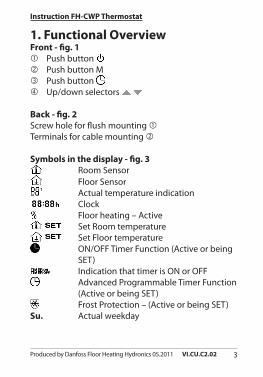
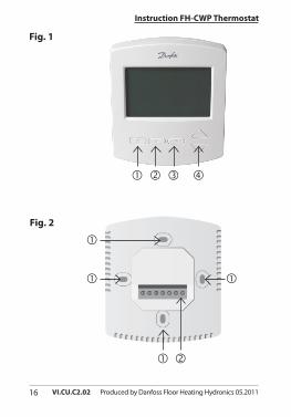
1. Functional OverviewFront - fig. 1 Push button Push button M Push button Up/down selectors
Back - fig. 2Screw hole for flush mounting Terminals for cable mounting
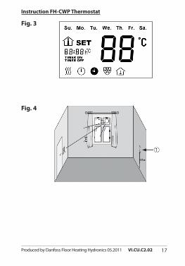
Symbols in the display - fig. 3 Room Sensor Floor Sensor Actual temperature indication
Clock Floor heating – Active
Set Room temperature Set Floor temperature
ON/OFF Timer Function (Active or being SET)
Indication that timer is ON or OFF Advanced Programmable Timer Function
(Active or being SET) Frost Protection – (Active or being SET)
Su. Actual weekday
4 VI.CU.C2.02 Produced by Danfoss Floor Heating Hydronics 05.2011
Instruction FH-CWP Thermostat
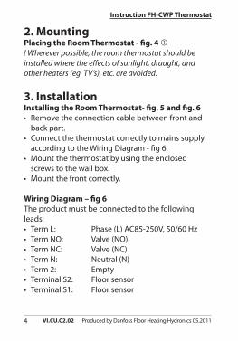
2. MountingPlacing the Room Thermostat - fig. 4 ! Wherever possible, the room thermostat should be installed where the effects of sunlight, draught, and other heaters (eg. TV’s), etc. are avoided.
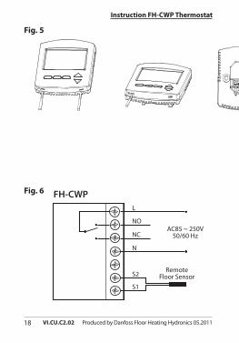
3. InstallationInstalling the Room Thermostat- fig. 5 and fig. 6• Remove the connection cable between front and
back part.• Connect the thermostat correctly to mains supply
according to the Wiring Diagram - fig 6.• Mount the thermostat by using the enclosed
screws to the wall box.• Mount the front correctly.
Wiring Diagram – fig 6The product must be connected to the following leads:• Term L: Phase (L) AC85-250V, 50/60 Hz• Term NO: Valve (NO)• Term NC: Valve (NC)• Term N: Neutral (N)• Term 2: Empty• Terminal S2: Floor sensor• Terminal S1: Floor sensor
5Produced by Danfoss Floor Heating Hydronics 05.2011 VI.CU.C2.02
Instruction FH-CWP Thermostat
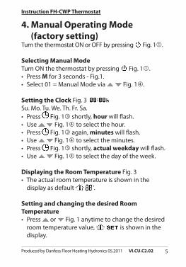
4. Manual Operating Mode (factory setting)Turn the thermostat ON or OFF by pressing Fig. 1.
Selecting Manual Mode Turn ON the thermostat by pressing Fig. 1.• Press M for 3 seconds - Fig.1.• Select 01 = Manual Mode via Fig. 1.
Setting the Clock Fig. 3 Su. Mo. Tu. We. Th. Fr. Sa.• Press Fig. 1 shortly, hour will flash.• Use Fig. 1 to select the hour.• Press Fig. 1 again, minutes will flash.• Use Fig. 1 to select the minutes.• Press Fig. 1 shortly, actual weekday will flash.• Use Fig. 1 to select the day of the week.
Displaying the Room Temperature Fig. 3• The actual room temperature is shown in the
display as default .
Setting and changing the desired Room Temperature • Press or Fig. 1 anytime to change the desired
room temperature value, is shown in the display.
6 VI.CU.C2.02 Produced by Danfoss Floor Heating Hydronics 05.2011
Instruction FH-CWP Thermostat
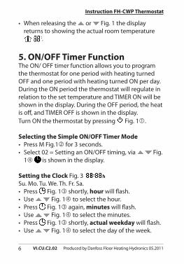
• When releasing the or Fig. 1 the display returns to showing the actual room temperature
.
5. ON/OFF Timer FunctionThe ON/ OFF timer function allows you to program the thermostat for one period with heating turned OFF and one period with heating turned ON per day. During the ON period the thermostat will regulate in relation to the set temperature and TIMER ON will be shown in the display. During the OFF period, the heat is off, and TIMER OFF is shown in the display.Turn ON the thermostat by pressing Fig. 1.
Selecting the Simple ON/OFF Timer Mode• Press M Fig.1 for 3 seconds.• Select 02 = Setting an ON/OFF timing, via Fig.
1 is shown in the display.
Setting the Clock Fig. 3 Su. Mo. Tu. We. Th. Fr. Sa.• Press Fig. 1 shortly, hour will flash.• Use Fig. 1 to select the hour.• Press Fig. 1 again, minutes will flash.• Use Fig. 1 to select the minutes.• Press Fig. 1 shortly, actual weekday will flash.• Use Fig. 1 to select the day of the week.
7Produced by Danfoss Floor Heating Hydronics 05.2011 VI.CU.C2.02
Instruction FH-CWP Thermostat
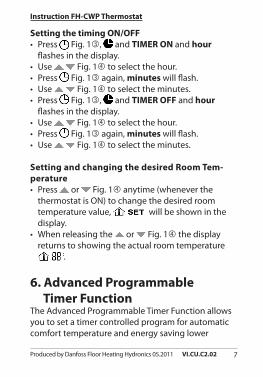
Setting the timing ON/OFF• Press Fig. 1, and TIMER ON and hour
flashes in the display.• Use Fig. 1 to select the hour.• Press Fig. 1 again, minutes will flash.• Use Fig. 1 to select the minutes.• Press Fig. 1, and TIMER OFF and hour
flashes in the display.• Use Fig. 1 to select the hour.• Press Fig. 1 again, minutes will flash.• Use Fig. 1 to select the minutes.
Setting and changing the desired Room Tem-perature • Press or Fig. 1 anytime (whenever the
thermostat is ON) to change the desired room temperature value, will be shown in the display.
• When releasing the or Fig. 1 the display returns to showing the actual room temperature
.
6. Advanced Programmable Timer Function The Advanced Programmable Timer Function allows you to set a timer controlled program for automatic comfort temperature and energy saving lower
8 VI.CU.C2.02 Produced by Danfoss Floor Heating Hydronics 05.2011
Instruction FH-CWP Thermostat
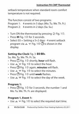
setback temperature when standard room comfort temperature is not required.
The function consist of two programsProgram 1: 4 events in 5 days (Mo. Tu. We. Th. Fr.)Program 2: 4 events in 2 days (Sa. Su.)
• Turn ON the thermostat by pressing Fig. 1.• Press M Fig. 1 for 3 seconds.• Select 03 = Setting a 5+2 days - 4 event setback
program via Fig. 1 is shown in the display.
Setting the Clock Fig. 3 Su. Mo. Tu. We. Th. Fr. Sa.• Press Fig. 1 shortly, hour will flash.• Use Fig. 1 to select the hour.• Press Fig. 1 again, minutes will flash.• Use Fig. 1 to select the minutes.• Press Fig. 1 until week flashes.• Use Fig. 1 to select the day of the week.
Program 1:• Press Fig. 1 for 3 seconds, the number 1 and
Mo. Tu. We. Th. Fr. are displayed.
Program 1, Event 1:• Use Fig. 1 to select the required start time.
9Produced by Danfoss Floor Heating Hydronics 05.2011 VI.CU.C2.02
Instruction FH-CWP Thermostat
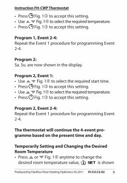
• Press Fig. 1 to accept this setting.• Use Fig. 1 to select the required temperature.• Press Fig. 1 to accept this setting.
Program 1, Event 2-4:Repeat the Event 1 procedure for programming Event 2-4.
Program 2:Sa. Su. are now shown in the display.
Program 2, Event 1:• Use Fig. 1 to select the required start time.• Press Fig. 1 to accept this setting.• Use Fig. 1 to select the required temperature.• Press Fig. 1 to accept this setting.
Program 2, Event 2-4:Repeat the Event 1 procedure for programming Event 2-4.
The thermostat will continue the 4-event pro-gramme based on the present time and day.
Temporarily Setting and Changing the Desired Room Temperature • Press or Fig. 1 anytime to change the
desired room temperature value, is shown
10 VI.CU.C2.02 Produced by Danfoss Floor Heating Hydronics 05.2011
Instruction FH-CWP Thermostat
in the display.• When releasing the or Fig. 1 the display
returns to showing the actual room temperature .
This temperature change is only temporary and will be maintained only until the next programmed setting!
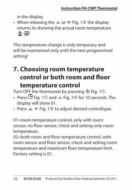
7. Choosing room temperature control or both room and floor temperature controlTurn OFF the thermostat by pressing Fig. 1.• Press Fig. 1 and Fig. 1 for 10 seconds. The
display will show 01.• Press Fig. 1 to adjust desired controltype.
01=room temperature control, only with room sensor, no floor sensor, check and setting only room temperature.02=both room and floor temperature control, with room sensor and floor sensor, check and setting room temperature and maximum floor temperature limit.Factory setting is 01.
11Produced by Danfoss Floor Heating Hydronics 05.2011 VI.CU.C2.02
Instruction FH-CWP Thermostat
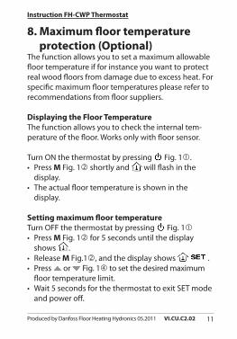
8. Maximum floor temperature protection (Optional)The function allows you to set a maximum allowable floor temperature if for instance you want to protect real wood floors from damage due to excess heat. For specific maximum floor temperatures please refer to recommendations from floor suppliers.
Displaying the Floor TemperatureThe function allows you to check the internal tem-perature of the floor. Works only with floor sensor.
Turn ON the thermostat by pressing Fig. 1.• Press M Fig. 1 shortly and will flash in the
display.• The actual floor temperature is shown in the
display.
Setting maximum floor temperatureTurn OFF the thermostat by pressing Fig. 1• Press M Fig. 1 for 5 seconds until the display
shows .• Release M Fig.1, and the display shows .• Press or Fig. 1 to set the desired maximum
floor temperature limit.• Wait 5 seconds for the thermostat to exit SET mode
and power off.
12 VI.CU.C2.02 Produced by Danfoss Floor Heating Hydronics 05.2011
Instruction FH-CWP Thermostat
9. Frost protection Using the Frost Protection Mode instead of turning the thermostat OFF completely may protect against dam-ages due to low temperatures. The room temperature will be maintained around 5 °C.
Turn OFF the thermostat by pressing Fig. 1.
• Press M Fig.1 for 3 seconds and release.• Select 01 (00= disabled).
If the temperature is lower than 5 °C the heating will be turned ON and will be shown in the display.If the temperature is higher than 7 °C the heating is turned OFF.Factory setting is 00.
10. Error messagesE1 will be displayed when room sensor failure.E2 will be displayed when floor sensor failure.E2 will be read when pressing M Fig. 1 to check floor temperature.Any case, all relay output would be turned off.
13Produced by Danfoss Floor Heating Hydronics 05.2011 VI.CU.C2.02
Instruction FH-CWP Thermostat
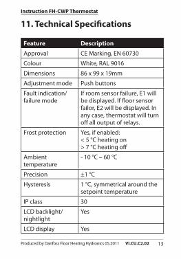
11. Technical Specifications
Feature Description
Approval CE Marking, EN 60730
Colour White, RAL 9016
Dimensions 86 x 99 x 19mm
Adjustment mode Push buttons
Fault indication/ failure mode
If room sensor failure, E1 will be displayed. If floor sensor failor, E2 will be displayed. In any case, thermostat will turn off all output of relays.
Frost protection Yes, if enabled:< 5 °C heating on> 7 °C heating off
Ambient temperature
- 10 °C – 60 °C
Precision ±1 °C
Hysteresis 1 °C, symmetrical around the setpoint temperature
IP class 30
LCD backlight/nightlight
Yes
LCD display Yes
14 VI.CU.C2.02 Produced by Danfoss Floor Heating Hydronics 05.2011
Instruction FH-CWP Thermostat
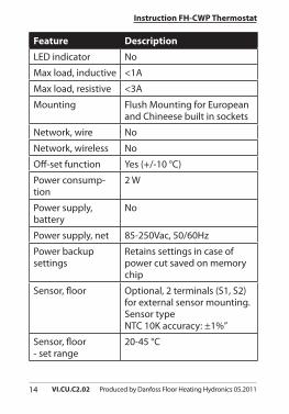
Feature Description
LED indicator No
Max load, inductive <1A
Max load, resistive <3A
Mounting Flush Mounting for European and Chineese built in sockets
Network, wire No
Network, wireless No
Off-set function Yes (+/-10 °C)
Power consump-tion
2 W
Power supply, battery
No
Power supply, net 85-250Vac, 50/60Hz
Power backup settings
Retains settings in case of power cut saved on memory chip
Sensor, floor Optional, 2 terminals (S1, S2) for external sensor mounting. Sensor typeNTC 10K accuracy: ±1%”
Sensor, floor - set range
20-45 °C
15Produced by Danfoss Floor Heating Hydronics 05.2011 VI.CU.C2.02
Instruction FH-CWP Thermostat
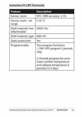
Feature Description
Sensor, room NTC 100K accuracy: ±1%
Sensor, room - set range
5-35 °C
Shell material/ non inflammable
94V0/ Yes
Shell material, type ABS+PC
Static protection Yes
Programmable Two program functions1. ON/ OFF program 2 periods /day
2. Periode program for auto-matic comfort temperature and setback temperature 4 periods/ 5+2 days
16 VI.CU.C2.02 Produced by Danfoss Floor Heating Hydronics 05.2011
Instruction FH-CWP Thermostat
Fig. 1
Fig. 2
17Produced by Danfoss Floor Heating Hydronics 05.2011 VI.CU.C2.02
Instruction FH-CWP Thermostat
Fig. 3
Fig. 4
18 VI.CU.C2.02 Produced by Danfoss Floor Heating Hydronics 05.2011
Instruction FH-CWP Thermostat
Fig. 5
Fig. 6 FH-CWPL
NO
NC
N
S2
S1
RemoteFloor Sensor
AC85 ~ 250V50/60 Hz
19Produced by Danfoss Floor Heating Hydronics 05.2011 VI.CU.C2.02
Instruction FH-CWP Thermostat

www.heating.danfoss.com