Embed Size (px)
DESCRIPTION
By Nishant Namdeo
Citation preview
Faculty advisor: soumitra panday
Team members Roll No.
Arun Patel 0610EC091005
Ashish Raikwar 0610EC091006
Mahendra Yadav 0610EC091016
Rahul Prajapati 0610EC091021
OUTLINE
Project description The framework for the home
automation The communication Mobile Interface Hardware connection
Conclusion
PROJECT DESCRIPTION
Designing and implementing a Mobile-Based Home Automation (HA) system by Power line controlling system
Controlling home appliances such as lights, electric doors, or any other application
OBJECTIVE

Developing a HA system that gives the user complete control over all aspects of his or her home
The automated system will have the ability to be controlled from a Mobile. Use a Mobile to turn on and off a
light, as well as monitor a door The real objective is to
Create a basic framework for a home monitoring system
The HARDWARE
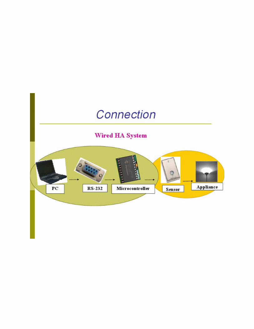
The main components needed to build a prototype
Mobile Interface Microcontrollers
Type Specification Circuit construction
Sensors Light module Door module

ATMEGA16 L
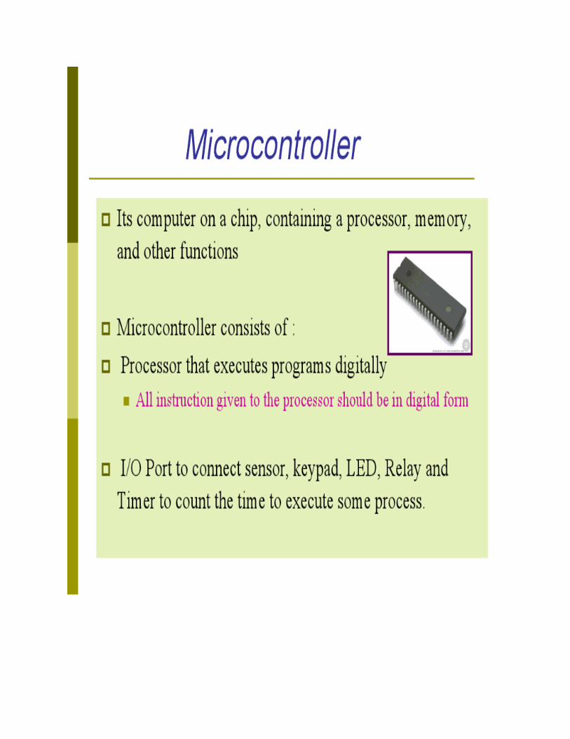
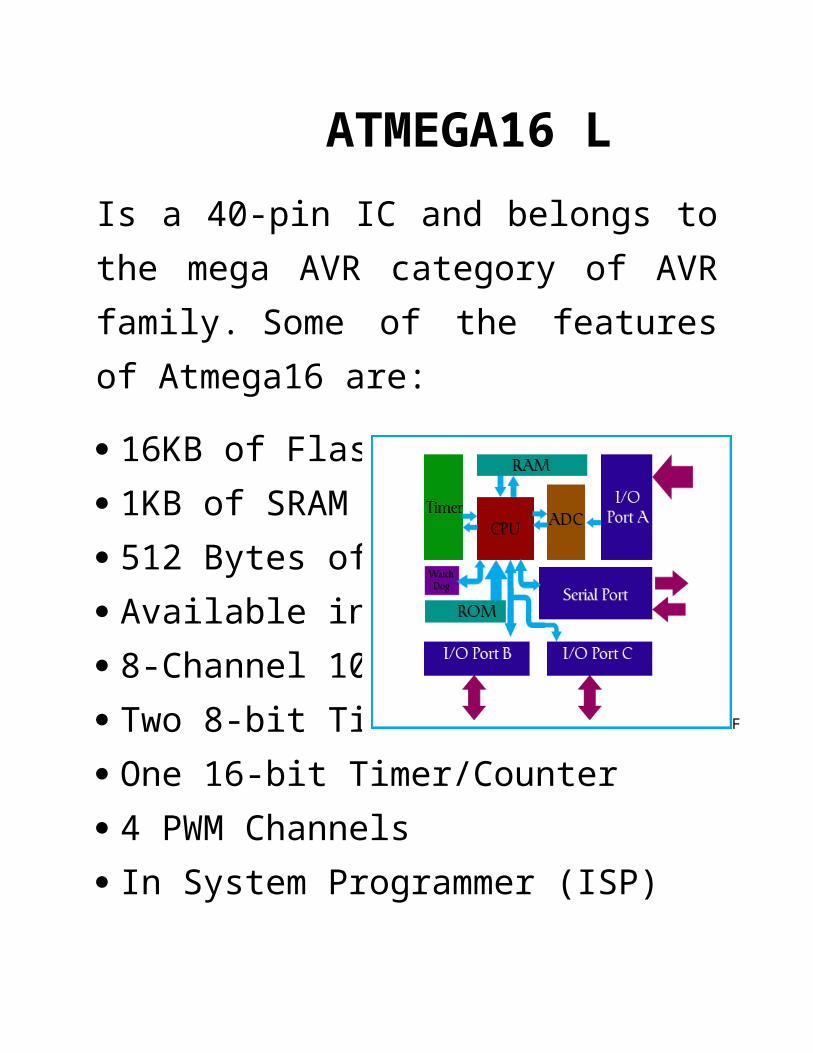
Is a 40-pin IC and belongs to the mega AVR category of AVR family. Some of the features of Atmega16 are:
16KB of Flash memory 1KB of SRAM 512 Bytes of EEPROM Available in 40-Pin DIP 8-Channel 10-bit ADC Two 8-bit Timers/Counters One 16-bit Timer/Counter 4 PWM Channels In System Programmer (ISP) Serial USART SPI Interface Digital to Analog Comparator.
Figure 3.2 atmega16 functional diagram
CHAPTER 3
ARCHITECTURE DIAGRAM: ATMEGA16
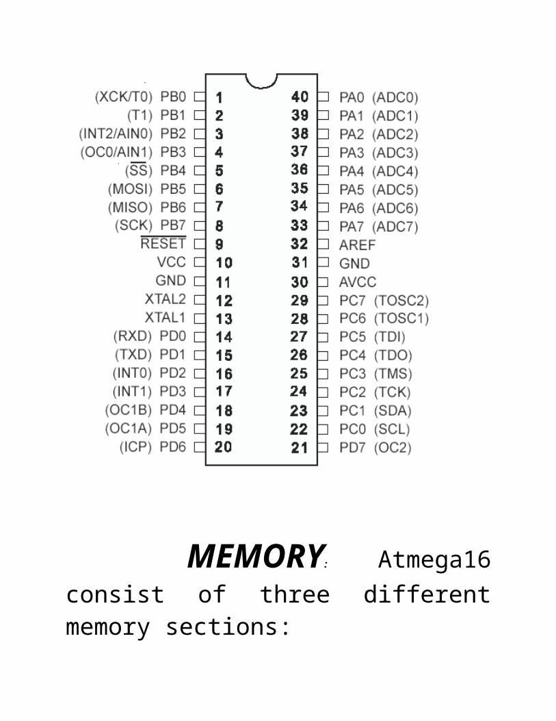
MEMORY: Atmega16 consist of three different memory sections:
1. Flash EEprom: Flash EEPROM
or simple flash memory is used to store the program dumped or burnt by the user on to the microcontroller. It can be easily erased electrically as a single unit. Flash memory is non-volatile i.e., it retains the program even if the power is cut-off. Atmega16 is available with 16KB of in system programmable Flash EEPROM.
2. Byte Addressable EEPROM:
This is also a nonvolatile memory used to store data like values of certain variables. Atmega16 has 512 bytes of EEPROM, this memory can be useful for storing the lock code if we are designing an application like electronic door lock.
3. SRAM: Static Random Access
Memory, this is the volatile memory of microcontroller i.e., data is lost as soon as power is turned off. Atmega16 is equipped with 1KB of internal SRAM. A small portion of SRAM is set aside for general purpose registers used by CPU and some for the peripheral subsystems of the microcontroller.
Internal calibrated oscillator:
Atmega16 is equipped with an internal oscillator for driving its clock. By default Atmega16 is set to operate at internal calibrated oscillator of 1 MHz. The maximum frequency of internal oscillator is 8Mhz. Alternatively, ATmega16 can be operated using an external crystal oscillator with a maximum frequency of 16MHz. In this case you need to modify the fuse bits.
ADC interface: (PORT A) Atmega16
is equipped with an 8 channel ADC (Analog to Digital Converter) with a resolution of 10-bits. ADC reads the analog input for e.g., a sensor input and converts it into digital information which is understandable by the microcontroller. Timers/counters: Atmega16 consists of two 8-bit and one 16-bit timer/counter. Timers are useful for generating precision actions for e.g., creating time delays between two operations. . The main features are:
Single Compare Unit Counter Clear Timer on Compare Match (Auto
Reload)
Glitch-free, Phase Correct Pulse Width Modulator (PWM)
Frequency Generator External Event Counter 10-bit Clock Prescaler Overflow and Compare Match Interrupt
Sources (TOV0 and OCF0)
Pwm: Atmega16 have 3 in built timers:
Timer0 Timer1 Timer2Timer 1 has 2 in built pwm channels which can be configured with 8 bit to 10 bit of resolutions.
Watchdog timer: is present with
internal oscillator. Watchdog timer continuously monitors and resets the
controller if the code gets stuck at any execution action for more than a defined time interval.
Interrupts: Atmega16 consists of 21
interrupt sources out of which four are external. The remaining are internal interrupts which support the peripherals like USART, ADC, Timers etc.
Usart: Universal Synchronous and
Asynchronous Receiver and Transmitter interface is available for interfacing with external device capable of communicating serially (data transmission bit by bit).
General purpose registers:
Atmega16 is equipped with 32 general
purpose registers which are coupled directly with the Arithmetic Logical Unit (ALU) of CPU.
ISP: AVR family of controllers have
In System Programmable Flash Memory which can be programmed without removing the IC from the circuit, ISP allows to reprogram the controller while it is in the application circuit. (PIN 6-11, excluding PIN10)
SPI: Serial Peripheral Interface, SPI
port is used for serial communication between two devices on a common clock source. The data transmission rate of SPI is more than that of USART.
TWI: Two Wire Interface (TWI) can be used to set up a network of devices, many devices can be connected over TWI interface forming a network, the devices can simultaneously transmit and receive and have their own unique address.
Microcontroller Specification The Specification for ATMEGA16 Microcontroller is very easy to
CHAPTER 3

Assembly Program
Low cost
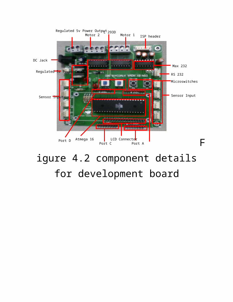
PORTS AND CONNECTOR DETAILS
Here is the detailed information of the NEXTSAPIENS Development Board –

Microswitches
Motor 1Motor 2L 293D
ISP header
Max 232
RS 232
Port CLCD Connector
Port A
Sensor Input
DC Jack
Regulated 5v Power Output
Sensor Input
Port D Atmega 16
Regulated 5v Power Output
Figure 4.2 component details for development board

HOME AUTOMATION BOARD
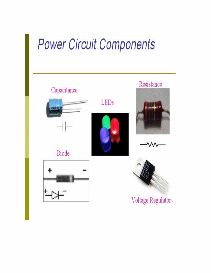
This board consists of a center tap transformer 12v-0-12v, capacitor, resistor, diodes, DPDT or SPDT relay, 817A Opto-coupler, TIP122.
CHAPTER 9

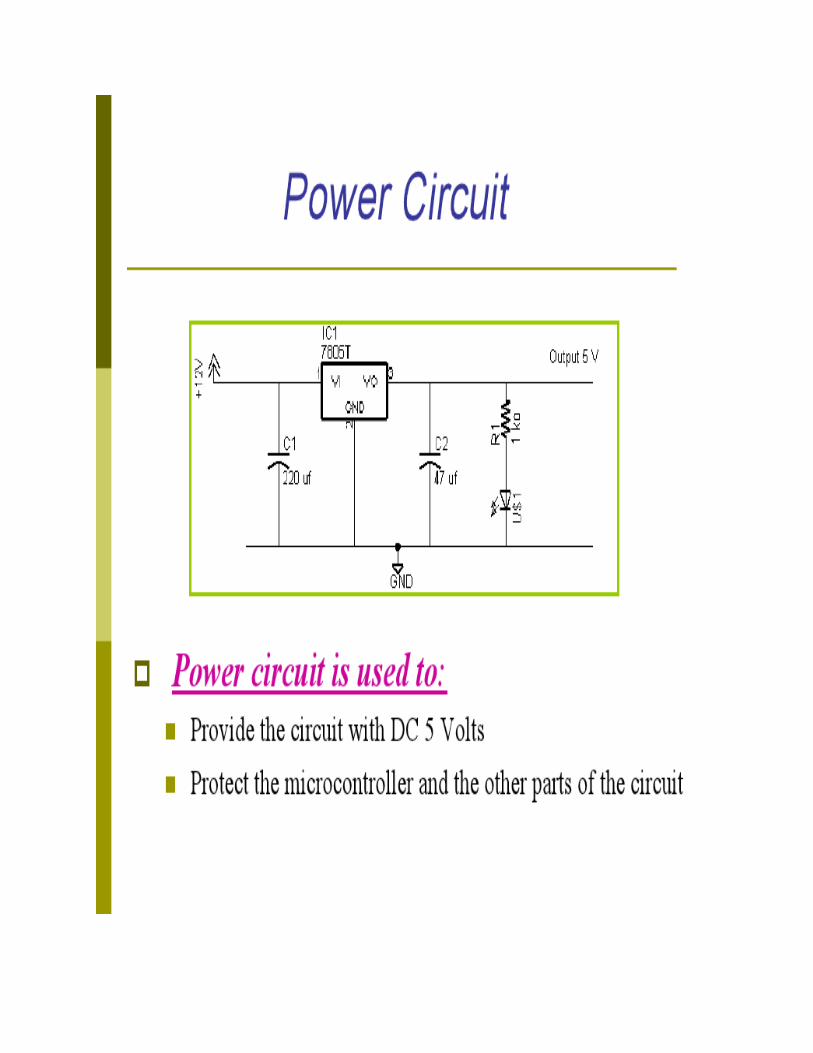
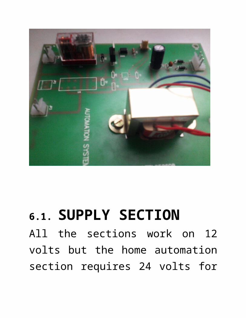
6.1. SUPPLY SECTIONAll the sections work on 12 volts but the home automation section requires 24 volts for its working. Therefore the 12 volts supply wire is cut into two parts which are then combined to give an output of 24volts. This supply is fed to a capacitor through a diode, so that the supply becomes uniform (without ripples).
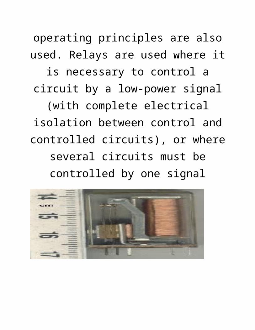
6.2. RELAYA relay is an electrically operated switch.
Many relays use an electromagnet to operate a switching mechanism mechanically, but other operating principles are also used. Relays are used where it is necessary to
control a circuit by a low-power signal (with
complete electrical isolation between control and controlled circuits), or where several circuits must be controlled by one signal
A simple electromagnetic relay consists of a coil of wire surrounding a soft iron core, an iron yoke which provides a low reluctance path for magnetic flux, a movable iron armature, and one or more sets of contacts (there are two in the relay pictured). The armature is hinged to the yoke and mechanically linked to one or more sets of moving contacts. It is held in
place by a spring so that when the relay is de-energized there is an air gap in the magnetic circuit. In this condition, one of the two sets of contacts in the relay pictured is closed, and the other set is open. Other relays may have more or fewer sets of contacts depending on their function.
TYPES OF RELAYSince relays are switches, the terminology applied to switches is also applied to relays. A relay will switch one or more poles, each of whose contacts can be thrown by energizing the coil in one of three ways:
The following designations are commonly encountered:
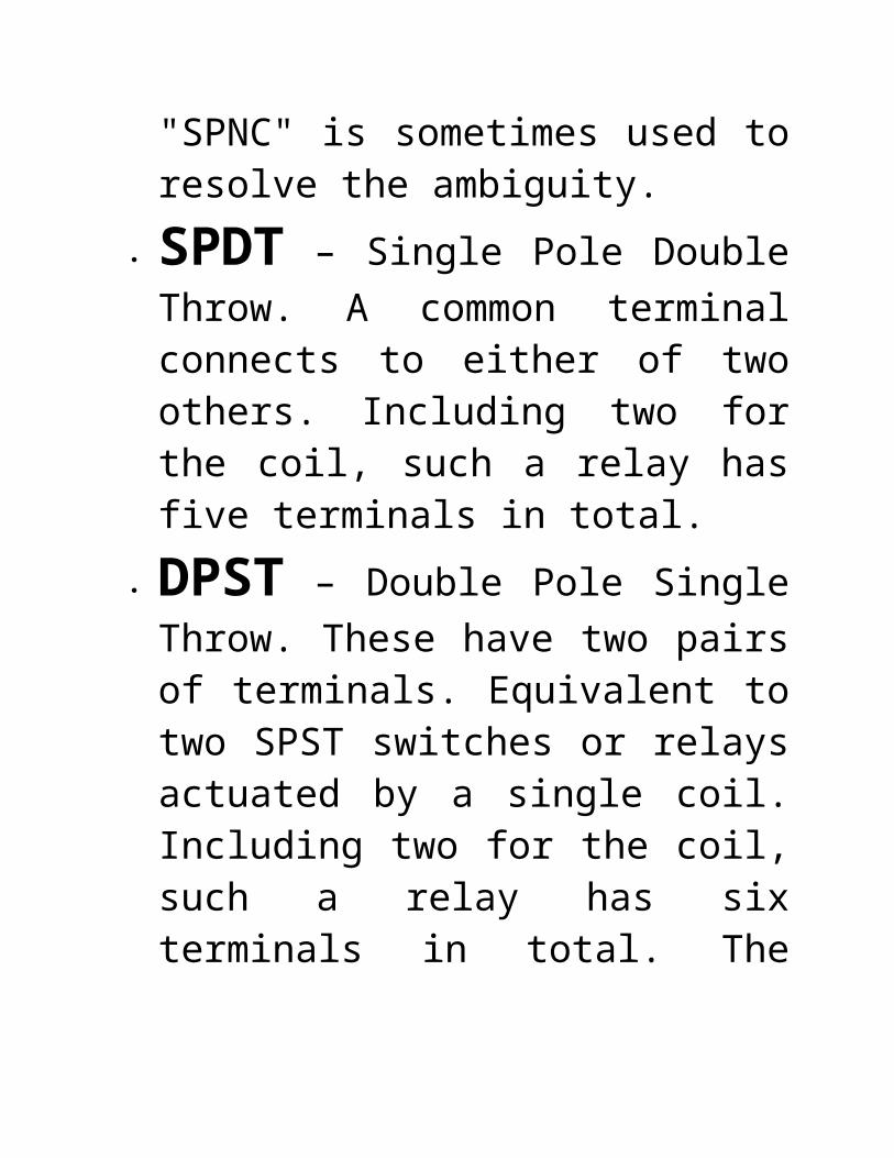
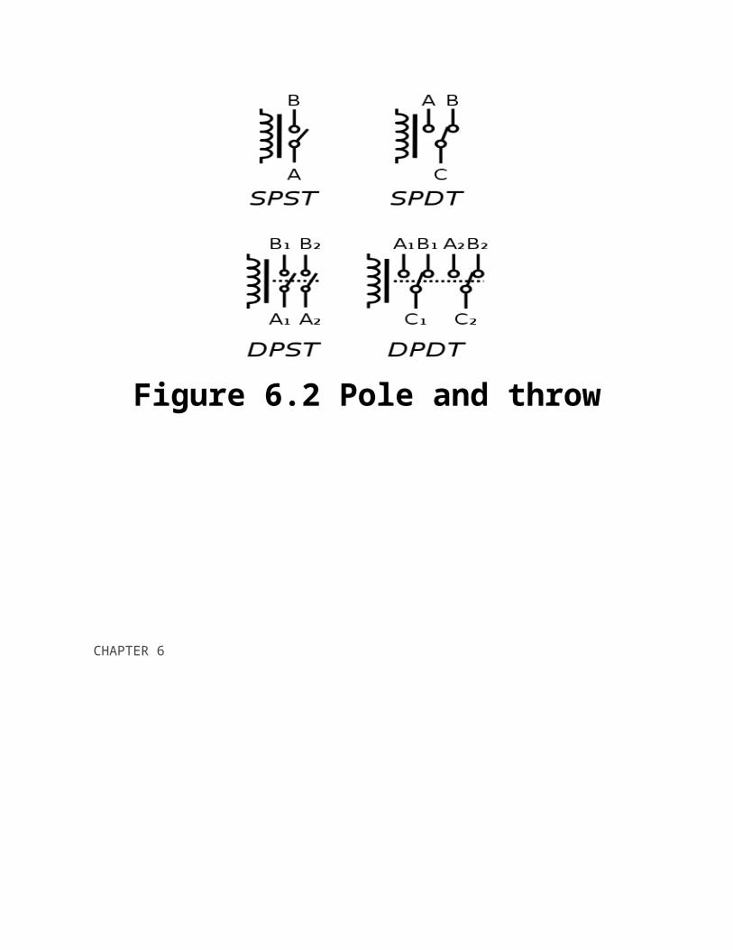
SPST – Single Pole Single Throw. These have two terminals which can be connected or disconnected. Including two for the coil, such a relay has four terminals in total. It is ambiguous whether the pole is normally open or normally closed. The terminology "SPNO" and "SPNC" is sometimes used to resolve the ambiguity.
SPDT – Single Pole Double Throw. A common terminal connects to either of two others. Including two for the coil, such a relay has five terminals in total.
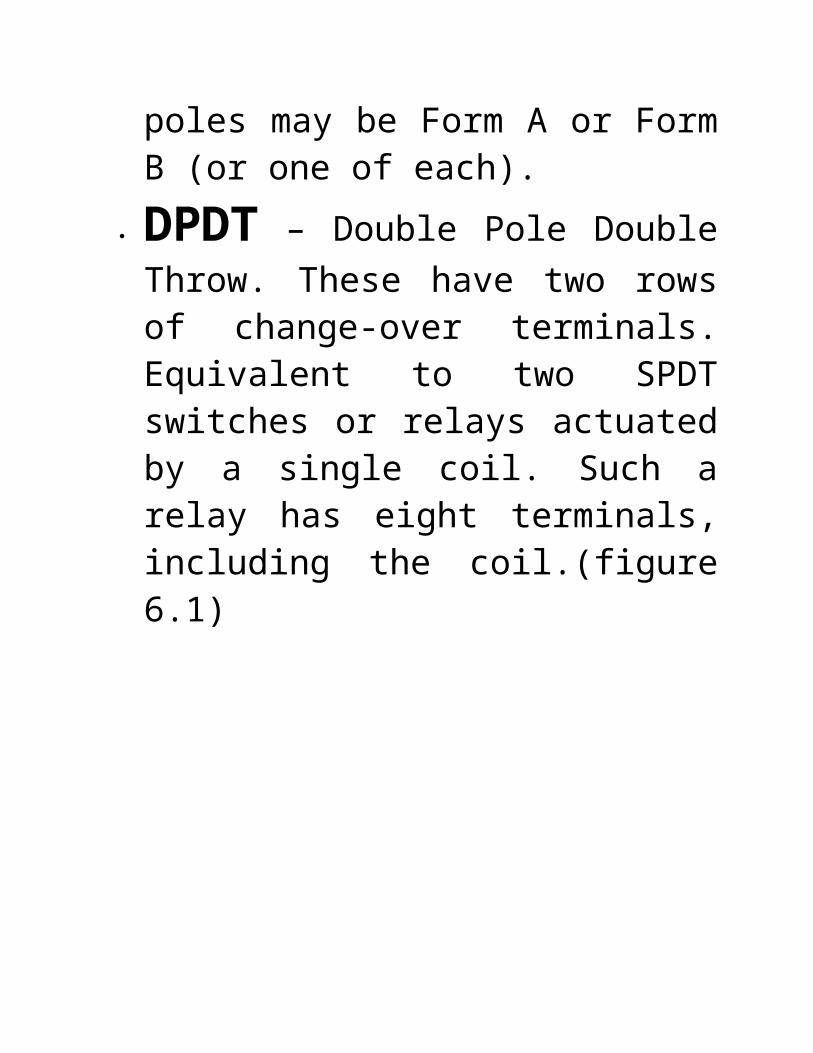
DPST – Double Pole Single Throw. These have two pairs of terminals. Equivalent to two SPST switches or relays actuated by a single coil. Including two for the coil, such a relay has six terminals in total. The poles may be Form A or Form B (or one of each).

DPDT – Double Pole Double Throw. These have two rows of change-over terminals. Equivalent to two SPDT switches or relays actuated by a single coil. Such a relay has eight terminals, including the coil.(figure 6.1)
Figure 6.2 Pole and throw
CHAPTER 6
Automatic bidirectional visitor counter
A counter that can change its state in either direction, under control of an up–down selector input, is known as an up–down counter. The circuit given here can count numbers from 0 to 9999 in up and down modes depending upon the state of the selector. It can be used to count the number of persons entering a hall in the up mode at entrance gate. In the down mode, it can count the number of persons leaving the hall by decrementing the count at exit gate. It can also be used at gates of parking areas and other public places.
This circuit divided in three parts:
sensor, controller and counter
display. The sensor would observe
an interruption and provide an input
to the controller which would run the
counter in up/down mode depending
upon the selector setting. The same
count is displayed on a set of 7-
segment displays through the
controller.
In this circuit, two infrared (IR)
sensor modules are used each for up
and down counting, respectively.
Whenever an interruption is observed
by the first IR sensor, it increments
the counter value. Similarly, when the
second sensor detects an obstacle,
the count is decremented
The count value is calculated
depending upon the sensors’ input
and is displayed on a set of four
seven segment displays by using the
concept of multiplexing (for concept
of multiplexing refer seven segment
multiplexing). The data pins of each
7-segment display are connected to
port P2 of the microcontroller
ATMEGA16 The first four pins of port
P1 (P1^0-P1^3) are connected to
control pins to enable a particular 7-
segment
This project is the most common and interesting to start with. The application is counting the number of persons entering in and exiting out like in Delhi Metro stations, Industries, offices, lift, car parking, and many more.
Our objective is to count the objects (persons) entering and exiting the room so we need some sensors to detect the objects and a control unit which calculates the object, below you can find the block diagram and circuit diagram which illustrate the solution and the Embedded ‘C’ source code which calculate the object. Remember that this circuit is used with GP_KIT_MCS51-2.02 from BISD Labs, New Delhi; the kit contains rest
of circuit like 8051 microcontroller, interfacing two digit seven segments, on board voltage regulator to provide +5V D.C, ISP circuit, and a lot. Also refer the user manual of this kit.
PRINCEPLEFrom the block diagram it is clear that
the sensor pairs are placed face to face so that an IR radiations from IR LED are continuously received by phototransistor which makes its emitter base junction forward and collector current Ic equals to emitter current Ie (i.e, Ic=Ie) assuming base current to be negligible. Hence the voltage at collector node becomes zero (logic 0) which is feed to microcontroller port pin P3.2 and P3.3, if any object is placed in between the sensor pair blocks the IR radiation which in turns put the phototransistor in cut-off mode and Ic!=Ie, this makes collector voltage to +5V (logic 1) In our program we have to poll both the inputs from both the sensors at port pin P3.2 and P3.3 to detect for the entry or
exit, if sensor pair one is been obstructed (P3.2 becomes one) first, implies persons entry and second pair is obstructed (P3.3 becomes one) first shows exit.
16 Pin LCD Header: A 16 Pin
header is provided to interface one 16 * 2 Alphanumeric LCD. Given below are the pin configuration details –
Lcdpin = Pin Db4 = Portb.4 Db5 = Portb.5 Db6 = Portb.6 Db7 = Portb.7 E = Portb.3 Rs = Portb.2 DB4 to DB7: = Data Buses of
LCD
E: = Enable pin of LCD Rs: = Register Select of LCD
These pin configuration are only for the LCD which is 16 * 2 alphanumeric display. For other type of LCD this may vary. Refer to related datasheet of the LCD incase if you are using a different one.
CONCLUSION
The entire report is presented in a chapter wise format, introducing level-to-
level components and their details. Atmega 16 and the control board that is the main processing part of the control unit is explained in the initial chapters.
Whenever a sensor detects a change in the environment or notification is generated, Atmega16 processes that information and
act according to the automation code burnt in its flash. The initial attempts of interrupt programming were dropped
due to limited availability of external INT pins (INT 0, INT1, INT2). The
DTMF(dual tone multi frequency) module that enables remote accessibility of the system is explained in chapter 5.
For home automation, the home
automation board is used that enables automatic switching of the appliances
based on the instruction code sent by the user via DTMF
HOME AUTOMATION SYSTEM
A
Synopsis Report
Submitted in partial fulfillment of the requirement for the award of
Degree of
BACHELOR OF ENGINEERING
In
Electronics and Communication Engineering
SESSION: 2012-13
Submitted to
RAJIV GANDHI PROUDYOGIKI VISHWAVIDHYALAYA,
BHOPAL (M.P.)
Submitted by
Arun Patel Ashish Raikwar Mahendra Yadav Rahul Prajapati
0610EC091005 0610EC091006 0610EC091016 0610EC091022
Under the Guidance of
Er. Somitra Pandey
Department of
Electronics & Communication Engineering
DEPARTMENT OF
ELECTRONICS AND COMMUNICATION ENGINEERING
Infinity Management and Engineering College, Sagar (M.P.) 470002
Name of Institute: Infinity Management and Engineering College, Sagar
Department : Electronics & Communication
CERTIFICATE
This is to certify that synopsis report entitled “ HOME AUTOMATION SYSTEM ” submitted to Rajiv Gandhi Proudyogiki Vishwavidhyalaya, Bhopal by Arun Patel Ashish Raikwar Mahendra Yadav Rahul
Prajapati is a partial fulfillment of the requirement for the award of the degree in B.E with specialization in Electronics and Communication. The matter embodied is the actual work by Arun Patel Ashish
Raikwar Mahendra Yadav Rahul Prajapati and this work has not been submitted earlier (in part or full) for the award of any other degree.
Candidate Name : Arun Patel Ashish Raikwar Mahendra Yadav Rahul Prajapati
Enrollment No : (0610EC091005 0610EC091006 0610EC091016 0610EC091022)
Er. Somitra Pandey
Guide, Department of Electronics
& Communication Engineering,
IMEC, Sagar
COUNTERSIGNED BY
Er. SOUMITRA PANDE DR. SHISHIR JAIN
Head, Department of Electronics Principal
& Communication Engineering, IMEC, Sagar
IMEC, Sagar
CERTIFICATE OF APPROVAL
The synopsis entitled “HOME AUTOMATION SYSTEM” being submitted by by Arun Patel
(0610EC091005), Ashish Raikwar (0610EC091006), Mahendra Yadav (0610EC091016) and Rahul Prajapati
(0610EC091022) has been examined by us and is hereby approved for the award of degree “Bachelor of
Engineering (Electronics and Communication)”, for which it has been submitted. It is understood that
by this approval that the undersigned do not necessarily endorse or approve any statement made,
opinion expressed or conclusion drawn therein, but approve the dissertation only for the purpose for
which it has been submitted.
(Internal Examiner) (External Examiner)
Date: Date: