Embed Size (px)
Citation preview
1
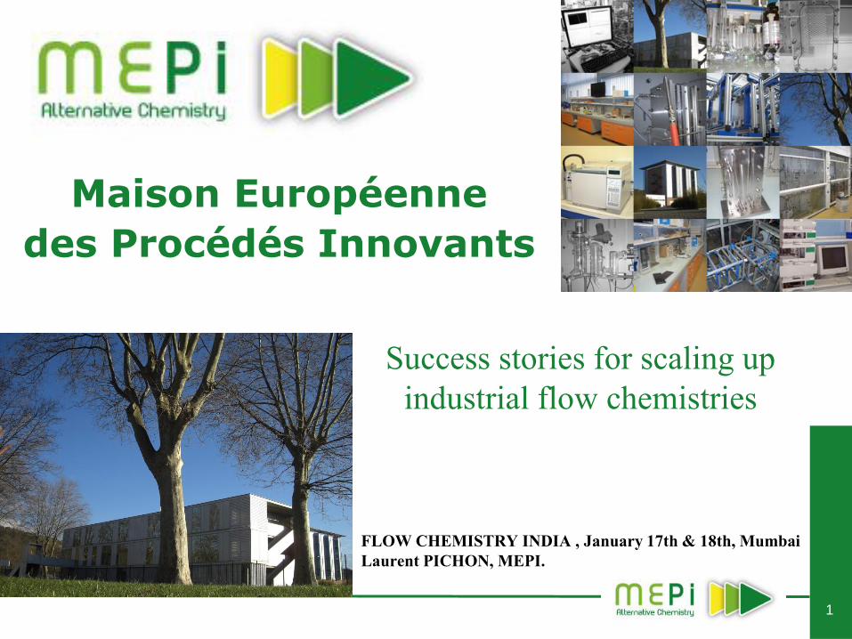
Maison Européenne
des Procédés Innovants
Success stories for scaling up
industrial flow chemistries
FLOW CHEMISTRY INDIA , January 17th & 18th, Mumbai
Laurent PICHON, MEPI.
2
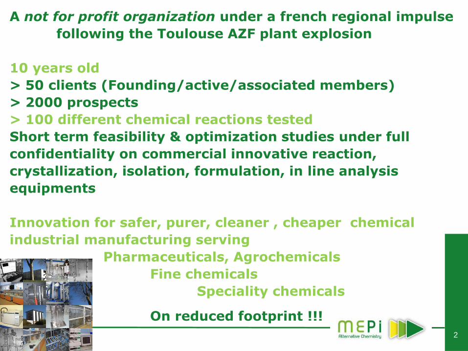
A not for profit organization under a french regional impulse
following the Toulouse AZF plant explosion
10 years old
> 50 clients (Founding/active/associated members)
> 2000 prospects
> 100 different chemical reactions tested
Short term feasibility & optimization studies under full
confidentiality on commercial innovative reaction,
crystallization, isolation, formulation, in line analysis
equipments
Innovation for safer, purer, cleaner , cheaper chemical
industrial manufacturing serving
Pharmaceuticals, Agrochemicals
Fine chemicals
Speciality chemicals
On reduced footprint !!!
3
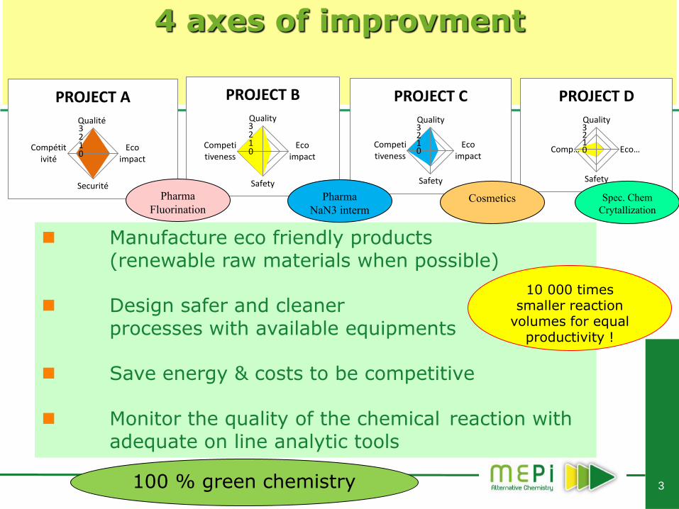
Manufacture eco friendly products (renewable raw materials when possible) Design safer and cleaner processes with available equipments Save energy & costs to be competitive Monitor the quality of the chemical reaction with adequate on line analytic tools
4 axes of improvment
100 % green chemistry
Qualité
Eco impact
Securité
Compétitivité
0 1 2 3
PROJECT A Quality
Eco impact
Safety
Competitiveness
0 1 2 3
PROJECT C Quality
Eco impact
Safety
Competitiveness
0 1 2 3
PROJECT B
Pharma
Fluorination
Pharma
NaN3 interm
Quality
Eco …
Safety
Comp… 0 1 2 3
PROJECT D
Cosmetics Spec. Chem
Crytallization
10 000 times smaller reaction
volumes for equal productivity !
4
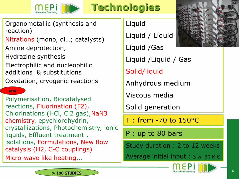
Technologies
Organometallic (synthesis and reaction)
Nitrations (mono, di…; catalysts)
Amine deprotection,
Hydrazine synthesis
Electrophilic and nucleophilic additions & substitutions
Oxydation, cryogenic reactions
Polymerisation, Biocatalysed reactions, Fluorination (F2), Chlorinations (HCl, Cl2 gas),NaN3 chemistry, epychlorohydrin, crystallizations, Photochemistry, ionic liquids, Effluent treatment , isolations, Formulations, New flow catalysis (H2, C-C couplings)
Micro-wave like heating...
Liquid
Liquid / Liquid
Liquid /Gas
Liquid /Liquid / Gas
Solid/liquid
Anhydrous medium
Viscous media
Solid generation
T : from -70 to 150°C
Study duration : 2 to 12 weeks
Average initial input : 3 w, 30 K €
P : up to 80 bars
5
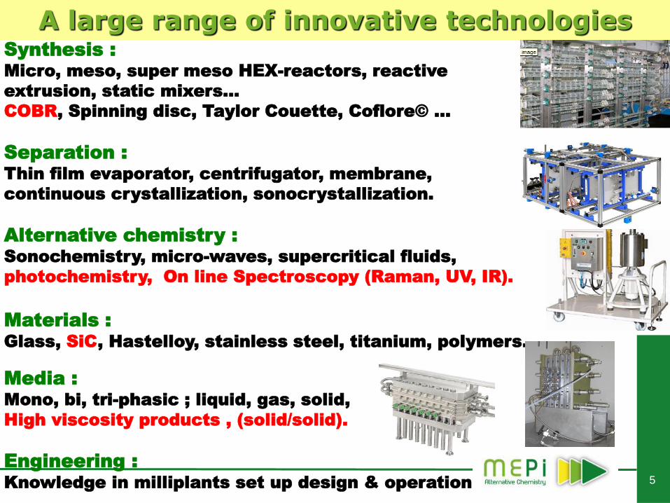
A large range of innovative technologies Synthesis :
Micro, meso, super meso HEX-reactors, reactive
extrusion, static mixers…
COBR, Spinning disc, Taylor Couette, Coflore© …
Separation :
Thin film evaporator, centrifugator, membrane,
continuous crystallization, sonocrystallization.
Alternative chemistry :
Sonochemistry, micro-waves, supercritical fluids,
photochemistry, On line Spectroscopy (Raman, UV, IR).
Materials :
Glass, SiC, Hastelloy, stainless steel, titanium, polymers.
Media :
Mono, bi, tri-phasic ; liquid, gas, solid,
High viscosity products , (solid/solid).
Engineering :
Knowledge in milliplants set up design & operation
6
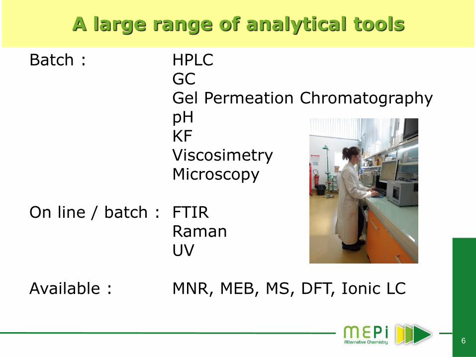
A large range of analytical tools
Batch : HPLC GC Gel Permeation Chromatography pH KF Viscosimetry Microscopy On line / batch : FTIR Raman UV Available : MNR, MEB, MS, DFT, Ionic LC
7
Key parameters for equipment choice
Reaction kinetics : Residence times up to 15 mn /up to 2 h => type of reactor, Heat generation & associated kinetics => type of reactor & heat exchange materials, Chemical corrosion => type of reactor / auxiliairies material, Chemical stability => temperature range, Type of media : Mono, bi, tri phasic Gas /Liquid/ solid Viscosity and evolution (pressure drop) Type of high viscosity media (sticky, slurry…), Initial Reaction conditions : Pressure, Temperature range Gas generation Solid generation, Industrial production volume & productivity expectations.
Assessment : Probability of success (go/no go), Preliminary study ? (batch Alternative chemistry : solvent, catalyst ?) Milliplant set up for faiseability…
8
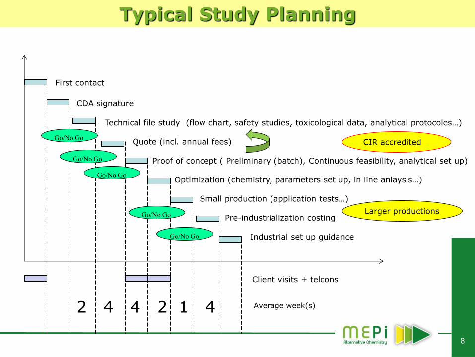
Typical Study Planning
First contact
CDA signature Technical file study (flow chart, safety studies, toxicological data, analytical protocoles…) Quote (incl. annual fees) Proof of concept ( Preliminary (batch), Continuous feasibility, analytical set up) Optimization (chemistry, parameters set up, in line anlaysis…) Small production (application tests…) Pre-industrialization costing Industrial set up guidance
Client visits + telcons
Average week(s) 2 4 4 2 1 4
CIR accredited
Go/No Go
Go/No Go
Go/No Go
Go/No Go
Go/No Go
Larger productions
9
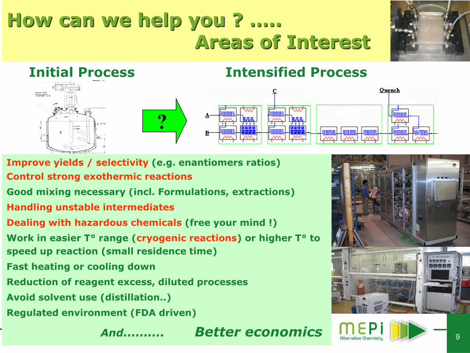
How can we help you ? ….. Areas of Interest
Intensified Process Initial Process
Improve yields / selectivity (e.g. enantiomers ratios)
Control strong exothermic reactions
Good mixing necessary (incl. Formulations, extractions)
Handling unstable intermediates
Dealing with hazardous chemicals (free your mind !)
Work in easier T° range (cryogenic reactions) or higher T° to
speed up reaction (small residence time)
Fast heating or cooling down
Reduction of reagent excess, diluted processes
Avoid solvent use (distillation..)
Regulated environment (FDA driven)
And………. Better economics
?
10
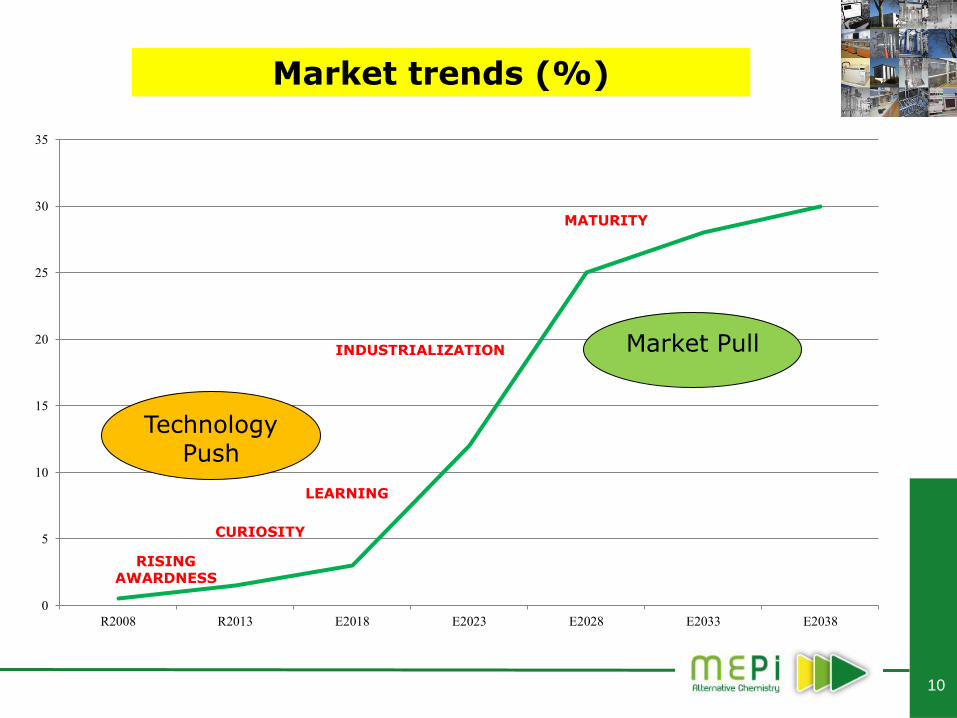
Market trends (%)
0
5
10
15
20
25
30
35
R2008 R2013 E2018 E2023 E2028 E2033 E2038
RISING AWARDNESS
CURIOSITY
MATURITY
LEARNING
INDUSTRIALIZATION
Technology Push
Market Pull
11
Oxidations in continuous
H2O2 NaOCl KMnO4
12
Sample
Raw material
solution
Catalyst
Solvent
Oxydizing
agent
precursor Pre-
heater
Pre-
heater
Mixer
T
Storage tank
Solvent
Res.
Time
T
Res.
Time
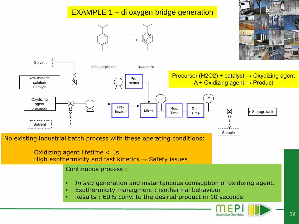
No existing industrial batch process with these operating conditions: Oxidizing agent lifetime < 1s High exothermicity and fast kinetics → Safety issues
Continuous process : • In situ generation and instantaneous comsuption of oxidizing agent. • Exothermicity managment : isothermal behaviour • Results : 60% conv. to the desired product in 10 seconds
Precursor (H2O2) + catalyst → Oxydizing agent
A + Oxidizing agent → Product
EXAMPLE 1 – di oxygen bridge generation
13
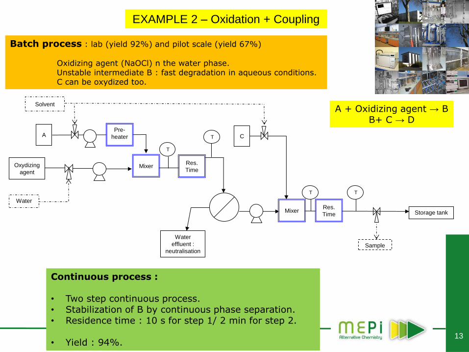
Batch process : lab (yield 92%) and pilot scale (yield 67%)
Oxidizing agent (NaOCl) n the water phase. Unstable intermediate B : fast degradation in aqueous conditions. C can be oxydized too.
Continuous process : • Two step continuous process. • Stabilization of B by continuous phase separation. • Residence time : 10 s for step 1/ 2 min for step 2.
• Yield : 94%.
A + Oxidizing agent → B B+ C → D
EXAMPLE 2 – Oxidation + Coupling
Sample
A
Solvent
Oxydizing
agent
Pre-
heater
Mixer
T
Storage tank
Water
Res.
Time
T
Res.
Time Mixer
C
T T
Water
effluent :
neutralisation
14
KMnO4 Oxidation
KMnO4 Solution
Solvent
RM
Cooling
Mixer Residence Time
T
I
Solvent
T <0°C
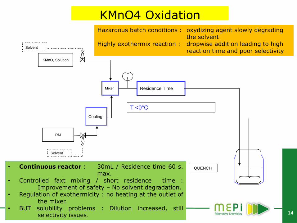
QUENCH • Continuous reactor : 30mL / Residence time 60 s. max.
• Controlled faxt mixing / short residence time : Improvement of safety – No solvent degradation.
• Regulation of exothermicity : no heating at the outlet of the mixer.
• BUT solubility problems : Dilution increased, still selectivity issues.
Hazardous batch conditions : oxydizing agent slowly degrading the solvent Highly exothermix reaction : dropwise addition leading to high reaction time and poor selectivity
15
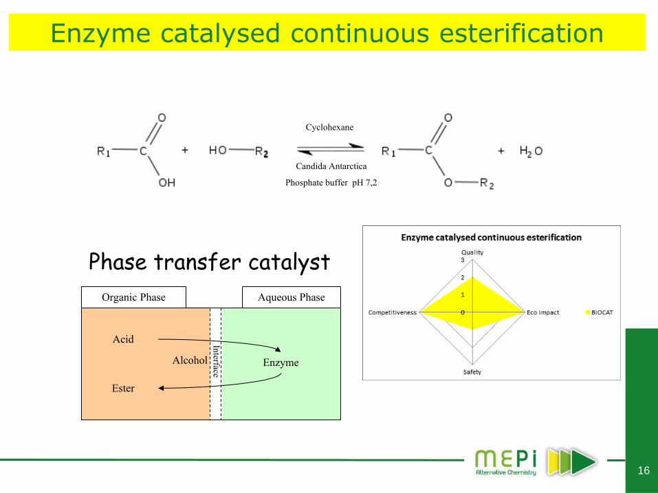
Enzyme catalysed continuous esterification
16
Candida Antarctica
Phosphate buffer pH 7,2
Cyclohexane
Acid
Ester
Alcohol
Organic Phase Aqueous Phase
Enzyme
Interface
Phase transfer catalyst
Enzyme catalysed continuous esterification
17
Reaction constraints
Two phase reaction
o Phase transfer catalyst in order to reach high conversion level
o High interfacial area required (strong mixing performances)
Kinetics
o Important reaction time (≈ 5 h in batch)
o Intermediate regime (kinetic and diffusion regimes compete)
Process
o Define an alternative continuous process to classical batch and loop reactors
o Possibility to reach important productivity
Enzyme catalysed continuous esterification
18
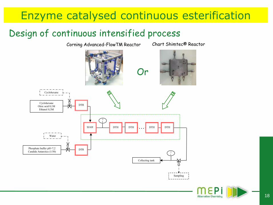
Design of continuous intensified process
Phosphate buffer pH=7,2
Candida Antarctica (1/50)
Cyclohexane
Oleic acid 0,1M
Ethanol 0,3M
Cyclohexane
DTR
DTR
SJAH
T
I
DTH
DTH
DTH
DTH
Corning Advanced-FlowTM Reactor
Sampling
T
I
Collecting tank
Water
…
Chart Shimtec® Reactor
Or
Enzyme catalysed continuous esterification
19
0
20
40
60
80
100
0 50 100 150 200 250 300
Time (min)
Co
nv
ers
ion
(%
)
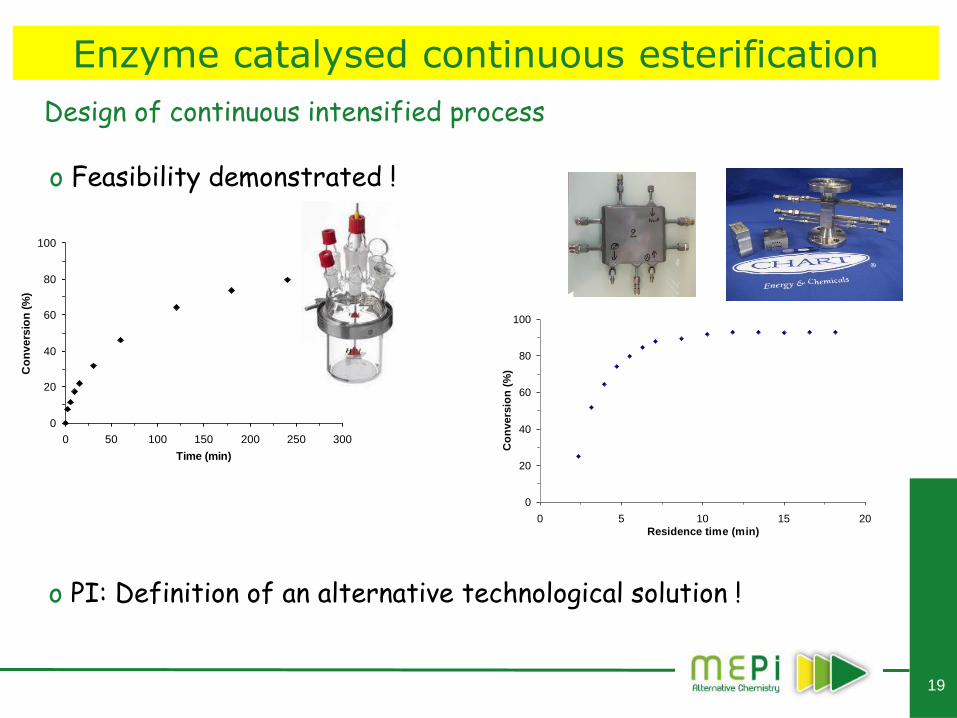
o Feasibility demonstrated !
o PI: Definition of an alternative technological solution !
Design of continuous intensified process
0
20
40
60
80
100
0 5 10 15 20
Residence time (min)
Co
nv
ers
ion
(%
)
Enzyme catalysed continuous esterification
20
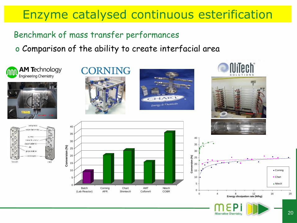
o Comparison of the ability to create interfacial area
Benchmark of mass transfer performances
0
5
10
15
20
25
30
35
40
Co
nv
ers
ion
(%
)
Batch
(Lab Reactor)
Corning
AFR
Chart
Shimtec®
AMT
Coflore®
Nitech
COBR0
5
10
15
20
25
30
35
40
0 4 8 12 16 20Energy dissipation rate (W/kg)
Co
nv
ers
ion
(%
)
Corning
Chart
Nitech
Enzyme catalysed continuous esterification
21
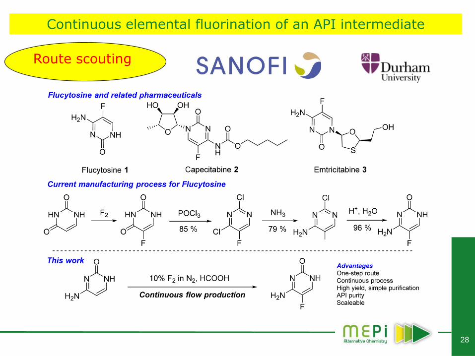
Continuous elemental fluorination
of an API intermediate
22
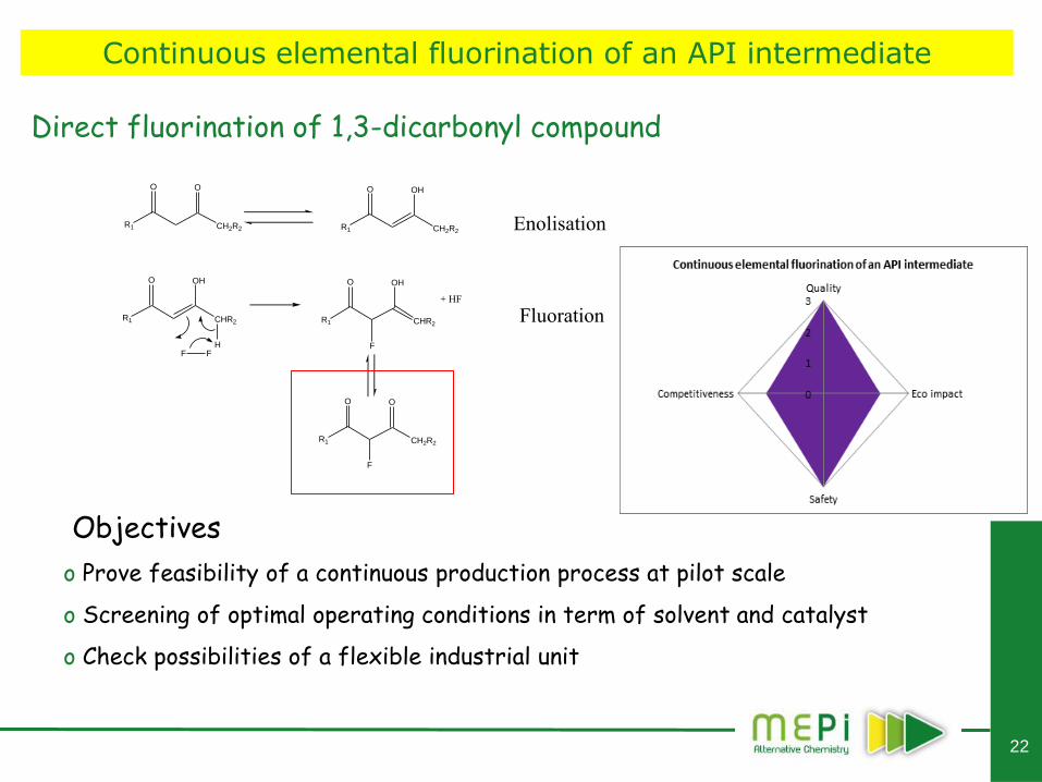
Direct fluorination of 1,3-dicarbonyl compound
CH2R2R1
O O
CH2R2R1
O OH
CHR2R1
O OH
F FH
CHR2R1
O OH
F
+ HF
CH2R2R1
O O
F
Enolisation
Fluoration
Objectives
o Prove feasibility of a continuous production process at pilot scale
o Screening of optimal operating conditions in term of solvent and catalyst
o Check possibilities of a flexible industrial unit
Continuous elemental fluorination of an API intermediate
23
Reaction constraints
No existing data related to the application
o No existing procedure for synthesis or extraction
• Thermo-kinetics (Safety !)
• Solvents, catalysts
o No analytical standard available for the desired product
Mixing
o Two phase reaction (Liquid / Gas)
o Strong gas hold-up (fluorine could be only purchased diluted in Nitrogen from 5 to 20%)
Safety
o Handling of a hazardous reagent (Fluorine)
o Corrosion (HF generation during reaction)
Continuous elemental fluorination of an API intermediate
24
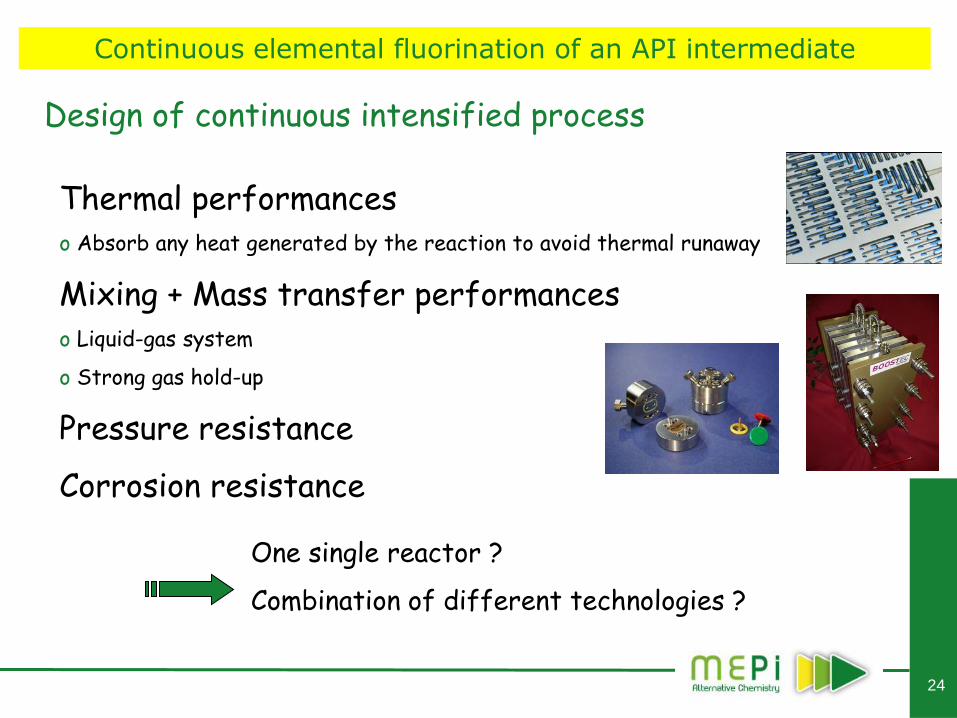
Design of continuous intensified process
Thermal performances o Absorb any heat generated by the reaction to avoid thermal runaway
Mixing + Mass transfer performances o Liquid-gas system
o Strong gas hold-up
Pressure resistance
Corrosion resistance
One single reactor ?
Combination of different technologies ?
Continuous elemental fluorination of an API intermediate
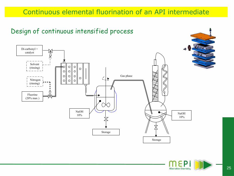
25
Di-carbonyl +
catalyst
Fluorine
(20% max )
Nitrogen
(rinsing)
Solvent
(rinsing)
NaOH
10%
Storage
Gas phase
Storage
NaOH
10%
Design of continuous intensified process
Continuous elemental fluorination of an API intermediate
26
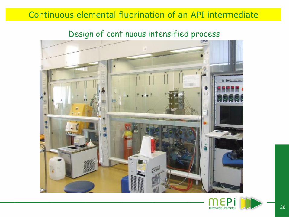
Design of continuous intensified process
Continuous elemental fluorination of an API intermediate
27
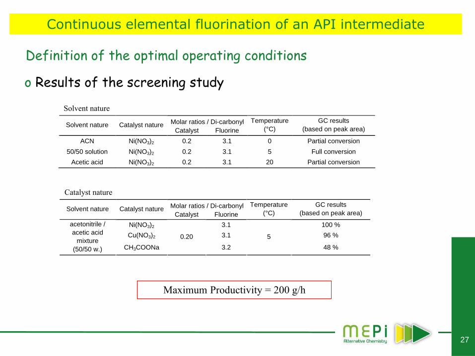
o Results of the screening study
Molar ratios / Di-carbonyl Solvent nature Catalyst nature
Catalyst Fluorine
Temperature
(°C)
GC results
(based on peak area)
ACN Ni(NO3)2 0.2 3.1 0 Partial conversion
50/50 solution Ni(NO3)2 0.2 3.1 5 Full conversion
Acetic acid Ni(NO3)2 0.2 3.1 20 Partial conversion
Molar ratios / Di-carbonyl Solvent nature Catalyst nature
Catalyst Fluorine
Temperature
(°C)
GC results
(based on peak area)
Ni(NO3)2 3.1 100 %
Cu(NO3)2 3.1 96 %
acetonitrile /
acetic acid
mixture
(50/50 w.) CH3COONa
0.20
3.2
5
48 %
Solvent nature
Catalyst nature
Maximum Productivity = 200 g/h
Definition of the optimal operating conditions
Continuous elemental fluorination of an API intermediate
29
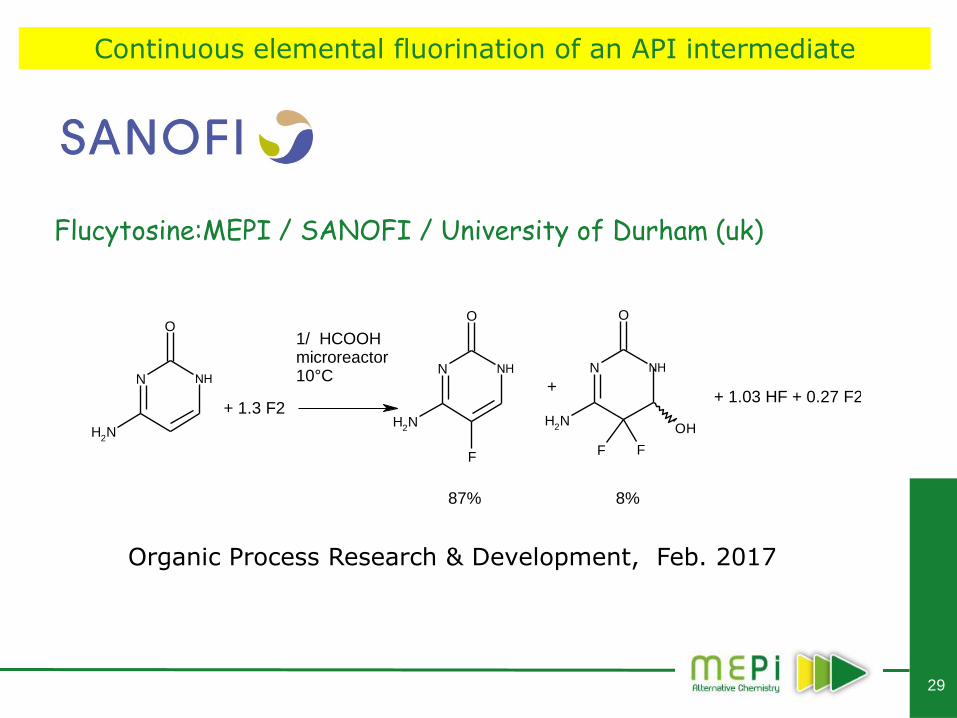
Flucytosine:MEPI / SANOFI / University of Durham (uk)
Continuous elemental fluorination of an API intermediate
N
O
OH
F F
NH2
NHN
NH2
O
NHN
O
NH2
F
NH
+
1/ HCOOH microreactor10°C
+ 1.3 F2+ 1.03 HF + 0.27 F2
87% 8%
Organic Process Research & Development, Feb. 2017
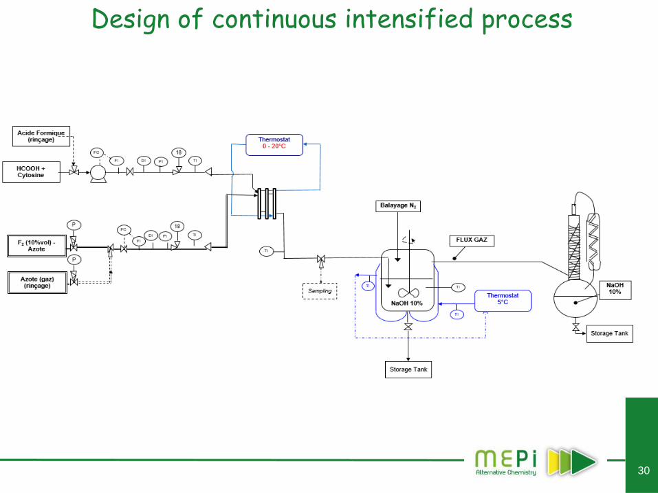
30
Design of continuous intensified process
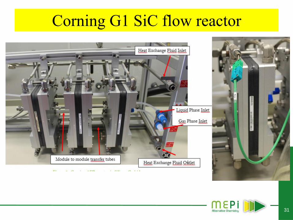
31
Corning G1 SiC flow reactor
32
Continuous carbonate synthesis
33
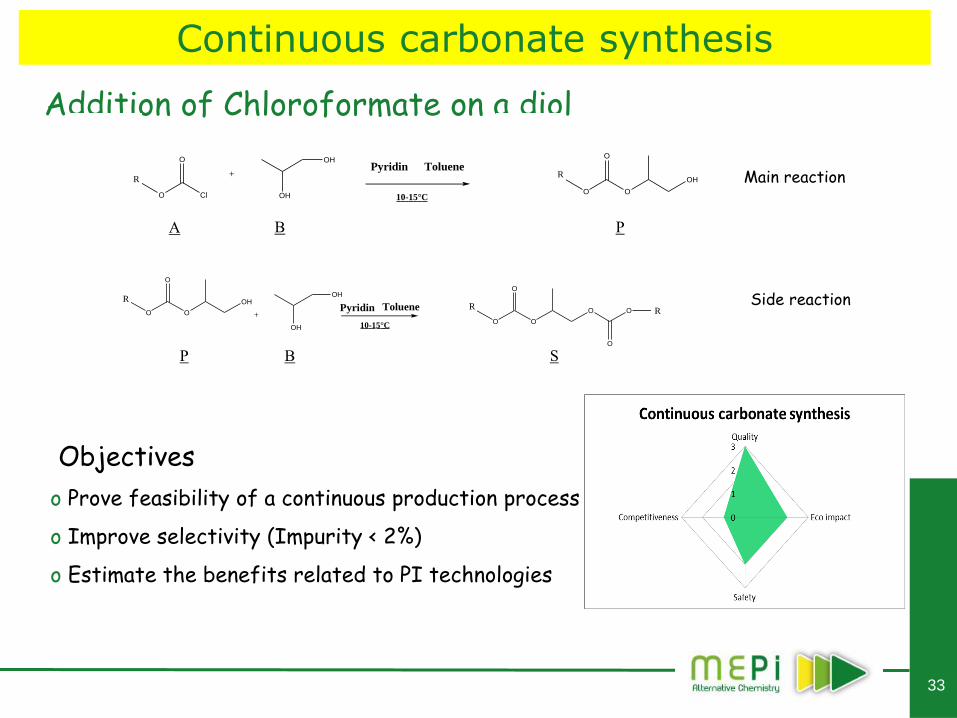
Addition of Chloroformate on a diol
Objectives
o Prove feasibility of a continuous production process
o Improve selectivity (Impurity < 2%)
o Estimate the benefits related to PI technologies
O Cl
O OH
OHO O
O
OH+
Pyridin Toluene
A BP
10-15°C
O O
O
O O
O
O O
O
OHOH
OH
+
S
Pyridin Toluene
10-15°C
Main reaction
Side reaction
R R
R R
R
A B P
P B S
Continuous carbonate synthesis
34
Reaction constraints
Two phase system (Liquid-Liquid)
o Chloroformate, Carbonate, Impurities Toluene Phase
o Diol Non miscible
Selectivity
o Necessity to slow down the main reaction (moderate temperature, reactant feeding)
o Large excess of Diol
o Constraint of less than 2% of dimer
Viscosity
Few data available
o No information on thermo-kinetics
o No data on solubility and phase equilibria
o Operating batch data at the production scale
Continuous carbonate synthesis
35
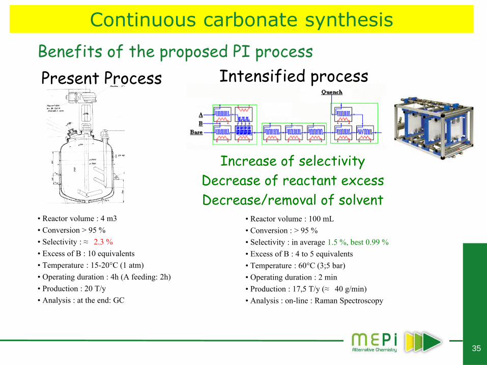
• Reactor volume : 100 mL
• Conversion : > 95 %
• Selectivity : in average 1.5 %, best 0.99 %
• Excess of B : 4 to 5 equivalents
• Temperature : 60°C (3;5 bar)
• Operating duration : 2 min
• Production : 17,5 T/y (≈ 40 g/min)
• Analysis : on-line : Raman Spectroscopy
Intensified process Present Process
Increase of selectivity
Decrease of reactant excess
Decrease/removal of solvent
• Reactor volume : 4 m3
• Conversion > 95 %
• Selectivity : ≈ 2.3 %
• Excess of B : 10 equivalents
• Temperature : 15-20°C (1 atm)
• Operating duration : 4h (A feeding: 2h)
• Production : 20 T/y
• Analysis : at the end: GC
Benefits of the proposed PI process
Continuous carbonate synthesis
36
FDA collaboration : demonstrate the concept of QbD
o Demonstrate the benefits of improved reactor design, effective sampling and online analytics to increase process understanding (QbD)
o Improve reaction development and optimization through the use of continuous flow reactors, NeSSI and online analytics
Continuous carbonate synthesis FDA study
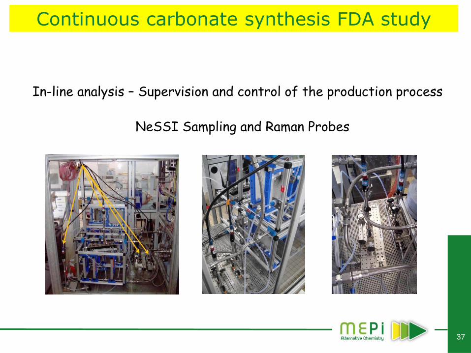
37
NeSSI Sampling and Raman Probes
In-line analysis – Supervision and control of the production process
Continuous carbonate synthesis FDA study
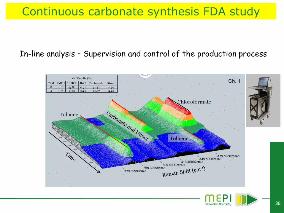
38
In-line analysis – Supervision and control of the production process
Continuous carbonate synthesis FDA study
39
Industrial production of
a Di-Nitrated compound
40
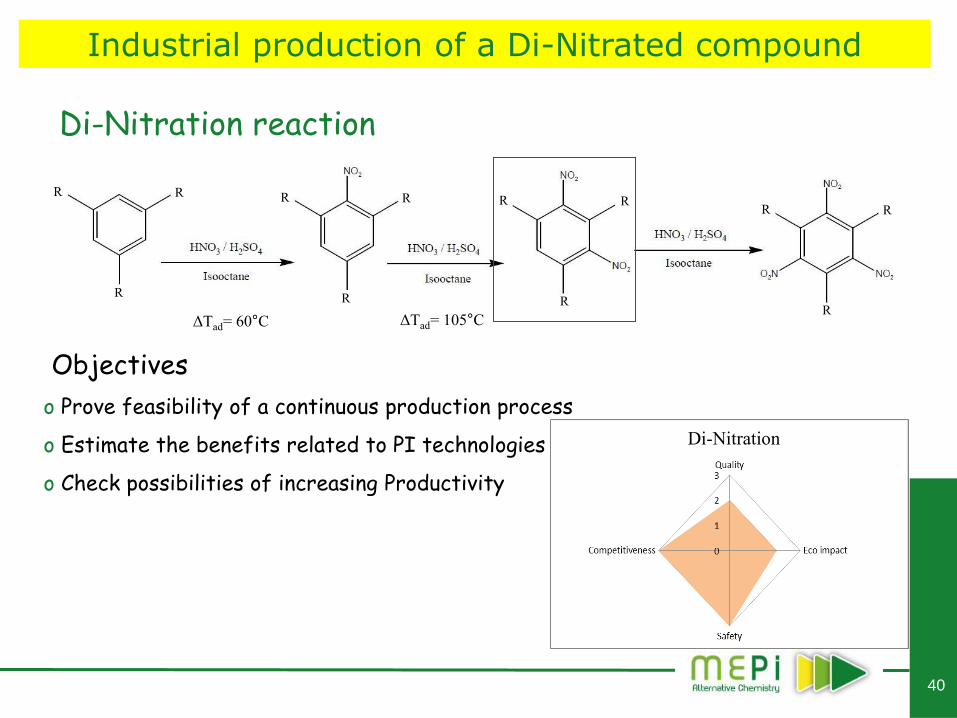
Di-Nitration reaction
Objectives
o Prove feasibility of a continuous production process
o Estimate the benefits related to PI technologies
o Check possibilities of increasing Productivity
Di-Nitration
R R
R
R R
R
R R
R
R R
R ΔTad= 60°C ΔTad= 105°C
Industrial production of a Di-Nitrated compound
41
Design of continuous intensified process : Reaction constraints
Accurate management of reactive medium temperature
o T < 35°C during feeding to avoid thermal runaway
o T > 60°C during reaction to avoid solid generation (Di-Nitro compound)
Fed-Batch process – Operating time of 14h !
Selectivity
o Excess of sulpho-nitric acids
o Strong influence of water contents
Use of high purity acids (HNO3 = 99%, H2SO4 = 98%)
Mixing
o Two phase reaction
o Strong difference of density (aqueous d ≈ 1.7, organic d ≈ 0.7)
Corrosion
Industrial production of a Di-Nitrated compound
42
Beginning of dropwise
addition (35°C) End of dropwise
addition (35°C) Beginning of contact
time (65°C)
End of contact time
(65°C)
o Poor thermal control
o Poor mixing
o Low kinetics
o Poor selectivity
64 % max. of Di-Nitro after 4h
Industrial production of a Di-Nitrated compound
Design of continuous intensified process : Batch reaction at lab-scale
43
Thermal performances o Estimation of the minimum required (UA/V)
Mixing + Mass transfer performances o Estimation of the mixing time required
o Determination of flow-rates and injections design
o Solid handling (?)
Corrosion
One single reactor ?
Combination of different technologies ?
Industrial production of a Di-Nitrated compound
Design of continuous intensified process
44
Transposition to continuous : “One pot” process
RM
Industrial production of a Di-Nitrated compound
Design of continuous intensified process
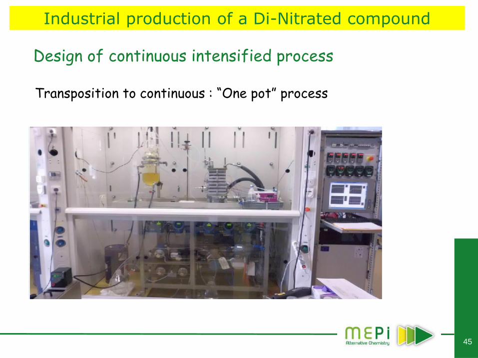
45
Transposition to continuous : “One pot” process
Industrial production of a Di-Nitrated compound
Design of continuous intensified process
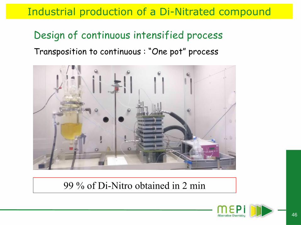
46
Transposition to continuous : “One pot” process
99 % of Di-Nitro obtained in 2 min
Industrial production of a Di-Nitrated compound
Design of continuous intensified process
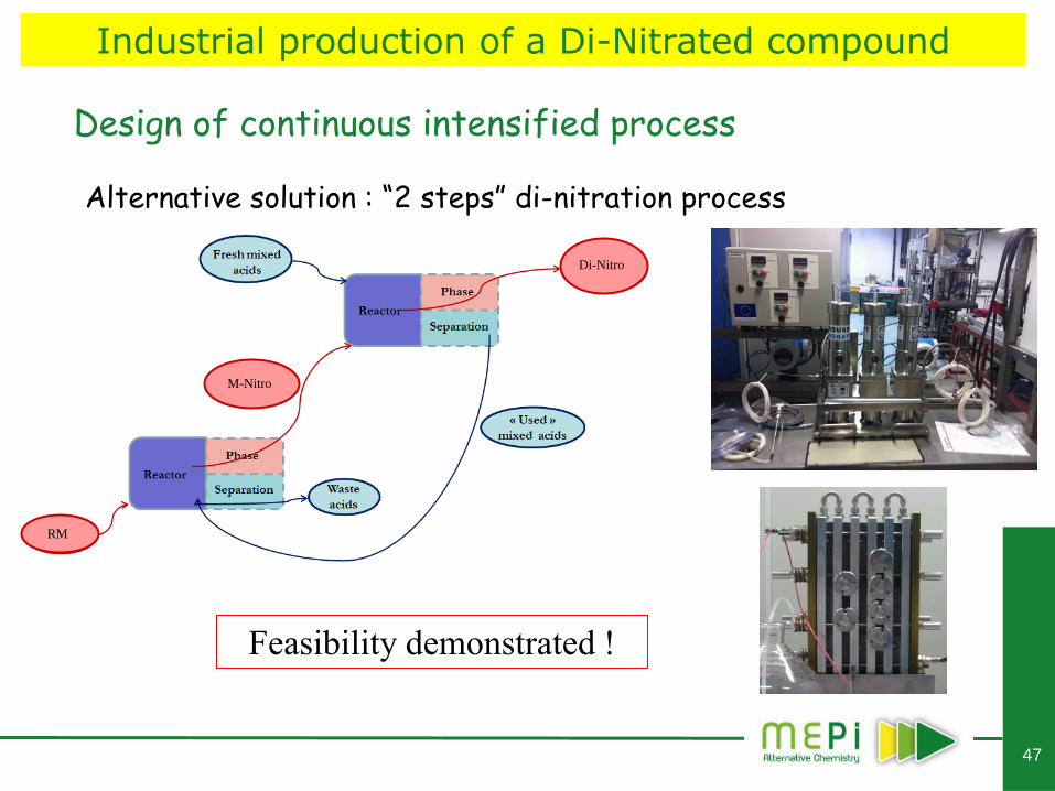
47
Alternative solution : “2 steps” di-nitration process
M-Nitro
Di-Nitro
RM
Feasibility demonstrated !
Industrial production of a Di-Nitrated compound
Design of continuous intensified process
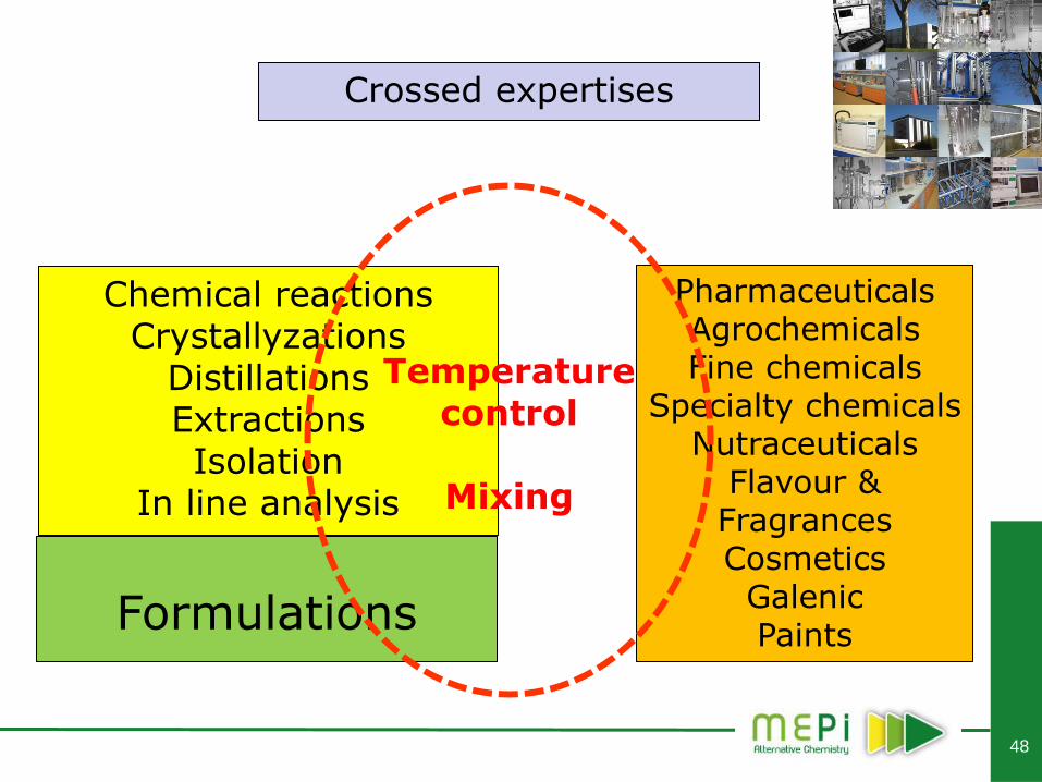
48
Chemical reactions Crystallyzations
Distillations Extractions Isolation
In line analysis
Pharmaceuticals Agrochemicals Fine chemicals
Specialty chemicals Nutraceuticals
Flavour & Fragrances Cosmetics
Galenic Paints
Formulations
Temperature control
Mixing
Crossed expertises
49
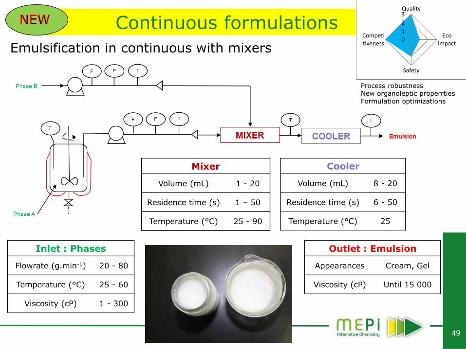
Continuous formulations
Emulsification in continuous with mixers
Inlet : Phases
Flowrate (g.min-1) 20 - 80
Temperature (°C) 25 - 60
Viscosity (cP) 1 - 300
Outlet : Emulsion
Appearances Cream, Gel
Viscosity (cP) Until 15 000
Mixer
Volume (mL) 1 - 20
Residence time (s) 1 – 50
Temperature (°C) 25 - 90
Cooler
Volume (mL) 8 - 20
Residence time (s) 6 - 50
Temperature (°C) 25
Quality
Eco impact
Safety
Competitiveness
0
1
2
3
Process robustness New organoleptic properrties Formulation optimizations
50
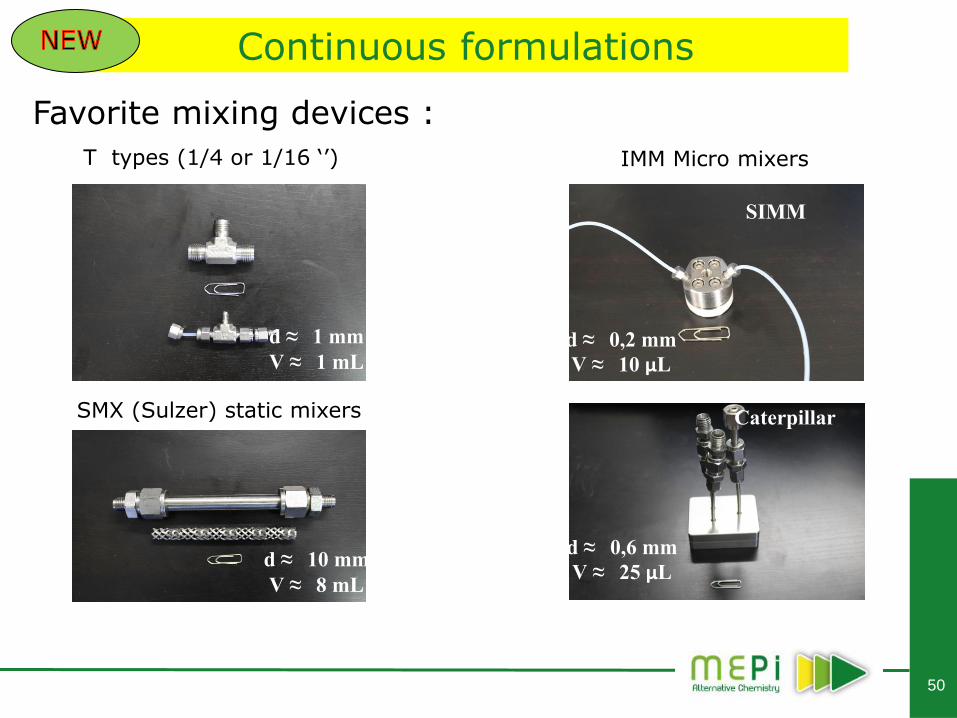
Continuous formulations
Favorite mixing devices :
T types (1/4 or 1/16 ‘’)
SMX (Sulzer) static mixers
IMM Micro mixers
d ≈ 1 mm
V ≈ 1 mL
d ≈ 10 mm
V ≈ 8 mL
d ≈ 0,2 mm
V ≈ 10 μL
d ≈ 0,6 mm
V ≈ 25 μL
SIMM
Caterpillar
51
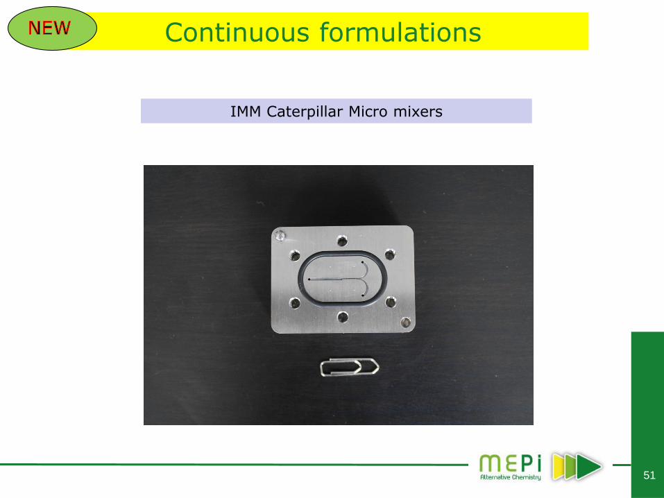
Continuous formulations
IMM Caterpillar Micro mixers
52
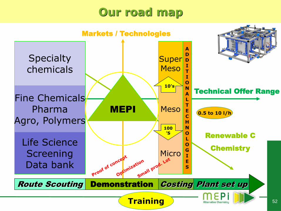
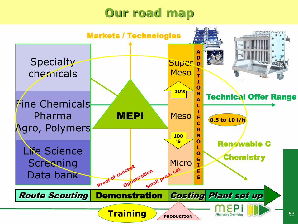
Specialty chemicals
Life Science Screening Data bank
Fine Chemicals Pharma
Agro, Polymers MEPI
Route Scouting Demonstration Costing Plant set up
Markets / Technologies
Renewable C
Chemistry
Technical Offer Range
Training
0.5 to 10 l/h
Super Meso
Micro
Meso
A D D I T I O N A L T E C H N O L O G I E S
Our road map
100’S
S, 01
10’s
53
Specialty chemicals
Life Science Screening Data bank
Fine Chemicals Pharma
Agro, Polymers MEPI
Route Scouting Demonstration Costing Plant set up
Markets / Technologies
Renewable C
Chemistry
Technical Offer Range
Training
0.5 to 10 l/h
Super Meso
Micro
Meso
A D D I T I O N A L T E C H N O L O G I E S
Our road map
100’S
S, 01
10’s
PRODUCTION
54
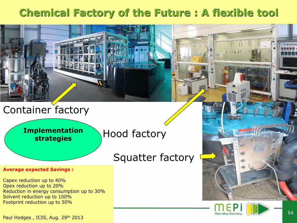
Chemical Factory of the Future : A flexible tool
Average expected Savings : Capex reduction up to 40% Opex reduction up to 20% Reduction in energy consumption up to 30% Solvent reduction up to 100% Footprint reduction up to 50%
Paul Hodges , ICIS, Aug. 29th 2013
Container factory Hood factory Squatter factory
Implementation strategies
55
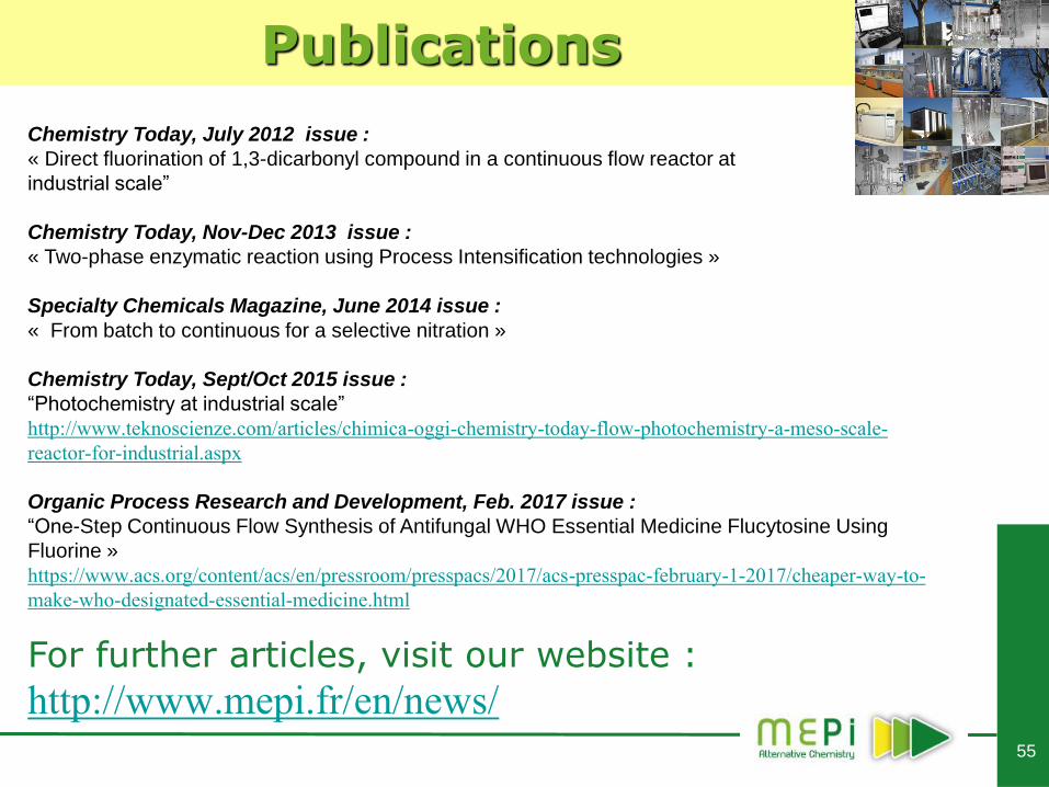
Publications
Chemistry Today, July 2012 issue :
« Direct fluorination of 1,3-dicarbonyl compound in a continuous flow reactor at
industrial scale”
Chemistry Today, Nov-Dec 2013 issue :
« Two-phase enzymatic reaction using Process Intensification technologies »
Specialty Chemicals Magazine, June 2014 issue :
« From batch to continuous for a selective nitration »
Chemistry Today, Sept/Oct 2015 issue :
“Photochemistry at industrial scale”
http://www.teknoscienze.com/articles/chimica-oggi-chemistry-today-flow-photochemistry-a-meso-scale-
reactor-for-industrial.aspx
Organic Process Research and Development, Feb. 2017 issue :
“One-Step Continuous Flow Synthesis of Antifungal WHO Essential Medicine Flucytosine Using
Fluorine »
https://www.acs.org/content/acs/en/pressroom/presspacs/2017/acs-presspac-february-1-2017/cheaper-way-to-
make-who-designated-essential-medicine.html
For further articles, visit our website :
http://www.mepi.fr/en/news/
56
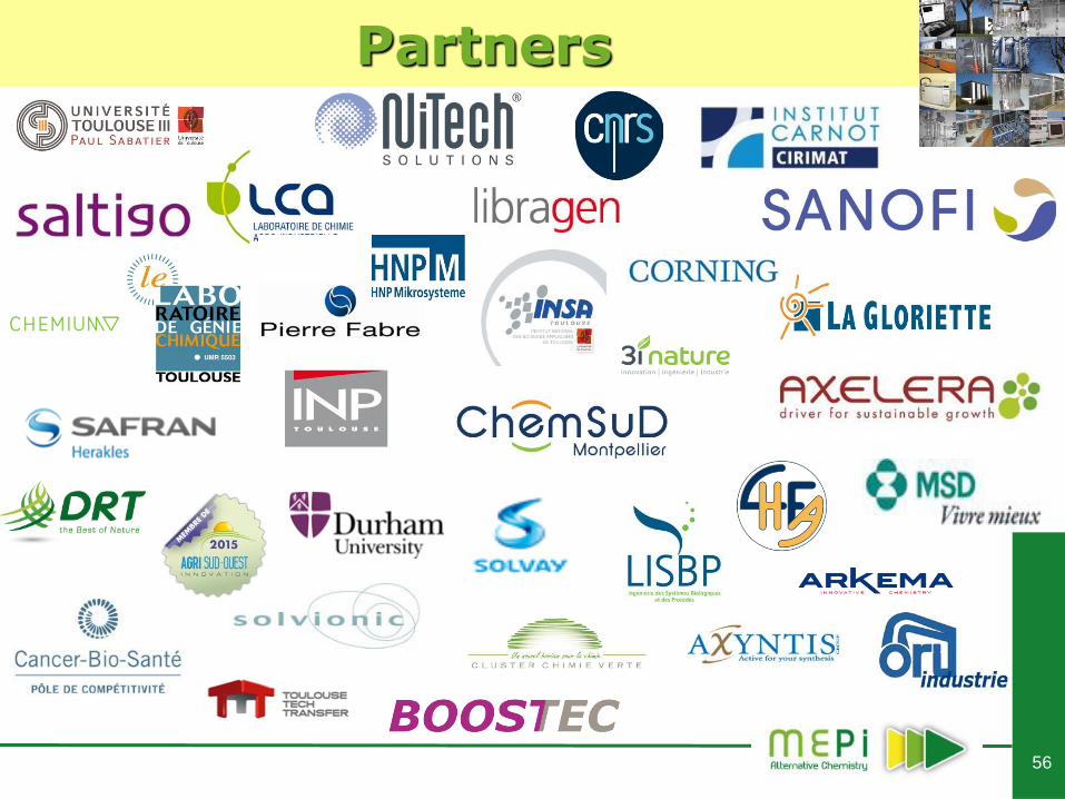
Partners
57
Sponsors
.
MEPI has been sponsored by

58
Mentors
.
« Simplicity is the utmost sophistication ! »
59
MEPI
Thank you for
your attention !
For further enquiries please contact:
Visit our website :
www.mepi.fr
Laurent PICHON
33+(6)73999531