Embed Size (px)
Citation preview

Maintenance
8505.13/3--10 MR / ACTELEC -- MAINTENANCE
INSTALLATIONMAINTENANCE
MR 400 to 1600ACTELEC 200 to 1600
1 General over view
2 Recommended tool
3 Installation
4 Adjustment of closing adjustable end stops
5 Actuator dismantling
6 Actuator greasing and re--assembly
7 Actuator valve coupling
8 Kit sheets : MR 400 / ACTELEC 200 / ACTELEC 400 Ref. 8507.8400/.--90MR 600 Ref. 8507.8600/.--90MR 800 / ACTELEC 500 / ACTELEC 800 Ref. 8507.8800/.--90MR 1200 Ref. 8507.8120/.--90MR 1600 / ACTELEC 950 / ACTELEC 1600 Ref. 8507.8160/.--90
9 Trouble shooting
KSB est certifié ISO 9001
MR / ACTELEC -- MAINTENANCE
2
This purpose of this document is to describe the installation/maintenance procedures and actions to be carried out in case ofbreakdowns or faulty operations of the manual actuators MR 400 to 1600 and electric actuators ACTELEC 200 to 1600.For ACTELEC electric servomotors, please consult the AUMA and/or BERNARD multiturns servomotors documentation.
1 -- General over viewManufacture range -- Characteristics
Type Manual actuatorOutput torque
NmIntput torque
NmNumber of turns for the
operating screw
ACTELEC 200 MR 400 2000 60 47
ACTELEC 400 MR 400 4000 110 47
ACTELEC 500 MR 800 5000 60 135
ACTELEC 800 MR 800 8000 110 135
ACTELEC 950 MR 1600 9500 60 285
ACTELEC 1600 MR 1600 16000 110 285
Manual actuators MR 400, 600 and 1200Handwheel control
970.2
Item Designation Item Designation Item Designation
103 Gear housing 412.3 O’ring 900.4 Screw
142 Cap 412.4 O’ring 901.1 Screw
160 Cover 412.5 O’ring 901.2 Screw
176 Bottom 412.6 O’ring 904 Screw
20--1 Operating screw 412.7 O’ring 916.2 Plug
310.1 Self--lubricating bearing 486 Ball 920.1 Operating screw
310.2 Self--lubricating bearing 554.1 Washer 920.2 Nut
310.3 Self--lubricating bearing 554.2 Washer 940 Woodfrut key
314 Thrust washer 59--40 Chuck + pointer shaft 961 Handwheel
325 Needles thrust 629 Pointer 970.1 Identity plate
32--5 Counter plate 81--68 Pressure pad 970.2 Position plate
412.1 O’ring 991 Grease
MR / ACTELEC -- MAINTENANCE
3
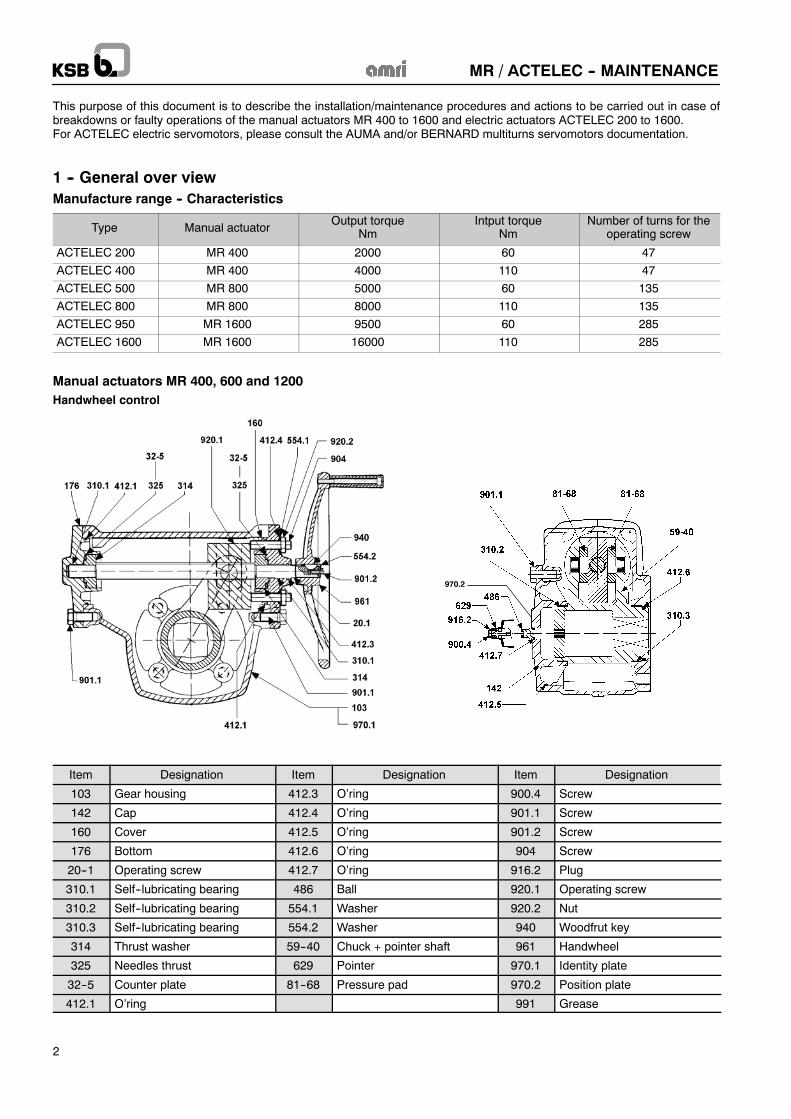
Manual actuators MR 800 and 1600Control by handwheel and input primary reduction gear
970.2
Item Designation Item Designation
103 Gear housing 554.2 Washer
142 Cap 59--40 Chuck + pointer shaft
160 Cover for adaptation motor F10 629 Pointer
176 Bottom 81--68 Pressure pad
20--1 Operating screw 872 Toothed wheel
310.1 Self--lubricating bearing 877 Pinion--shaft
310.2 Self--lubricating bearing 900.4 Screw
310.3 Self--lubricating bearing 901.1 Screw
310.4 Bearing 901.2 Screw
314 Thrust washer 901.3 Screw
325 Needles thrust 904 Screw
32--5 Counter plate 916.2 Plug
412.1 O--ring 920.1 Operating nut
412.2 O--ring 920.2 Nut
412.3 O--ring 940.1 Woodfrut key
412.4 O--ring 940.2 Parallel key
412.5 O--ring 961 Handwheel
412.6 O--ring 970.1 Identity plate
486 Ball 970.2 Position plate
554.1 Washer 991 Grease
MR / ACTELEC -- MAINTENANCE
4
2 -- RECOMMENDED TOOL (not supplied)
-- Pneumatic screwing machine-- Open ended spanner 16, 24-- Allen key 6 pans 4, 5 and 8-- 2 brushes for grease: the brushes must not loose its hair (one for cleaning out the old grease and one for greasing)
CONSUMABLES-- Grease Multi MS2 (Total), EPEXELF MO2 (Elf) or RETINAX AM (Shell) or equivalent.You need a quantity of 250 to 450ml. If you have a surplus in grease, it is not a problem for the correct operation of thesemanualactuators.
-- Glue Loctite 242 or equivalent.-- Flange sealant Loctite 58--14 or 58--31, Omnifit FD30 or equivalent-- KSB spare parts kits, according to the actuator size (see kit sheets at the end of the document).
3 -- INSTALLATION
BEFORE ANY ACTION
-- Index the mounting position of the actuator onto the valve-- Index the position of the pointer 629 or of the flag. Pointer position or flag position show the valve position.
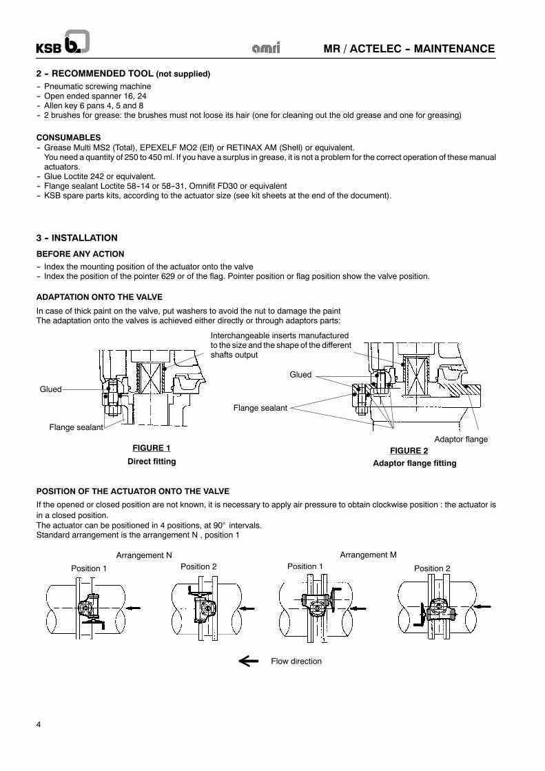
ADAPTATION ONTO THE VALVE
In case of thick paint on the valve, put washers to avoid the nut to damage the paintThe adaptation onto the valves is achieved either directly or through adaptors parts:
Interchangeable inserts manufacturedto the size and the shape of the differentshafts output
Flange sealant
FIGURE 1 FIGURE 2Direct fitting Adaptor flange fitting
••
•Glued •
Glued •• ••
Flange sealant
•
Adaptor flange
•
••
POSITION OF THE ACTUATOR ONTO THE VALVE
If the opened or closed position are not known, it is necessary to apply air pressure to obtain clockwise position : the actuator isin a closed position.The actuator can be positioned in 4 positions, at 90° intervals.Standard arrangement is the arrangement N , position 1
Arrangement N Arrangement M
Position 1 Position 1Position 2 Position 2
Flow direction

MR / ACTELEC -- MAINTENANCE
5
TRANSFORMATION Arrangement N Arrangement M
-- Close the valveIn the case of offset disc valve, empty the pressure of the pipe
-- Uncouple the actuator from the valve,-- Remove the plug 916.2, the screw 900.4 and the pointer 629 or other accessories such as box, flag, etc...,-- Remove the two balls 486 out of their grooves using a screwdriver, pin punch, . . .-- Insert in the groove at 90 ° the balls 486 of the spare part kit,-- Refit the position plate 970.2 (if any, in case of pointer or flag) at 90° from its initial position and retighten its screws.-- Mount the plug 916.2, the screw 900.4 and the pointer 629 or other accessories such as box, flag, e.g. in its initial position andscrew the screw 900.4,
-- Clean the surface and use sealant paste.-- Refit the actuator onto the valve at 90° of the initial position .
CAUTION : if a limit switch box is fitted onto the actuator, the adjustments must be modified following the instructions given in theuser guide document of the correspondant box.
486
MR / ACTELEC -- MAINTENANCE
6
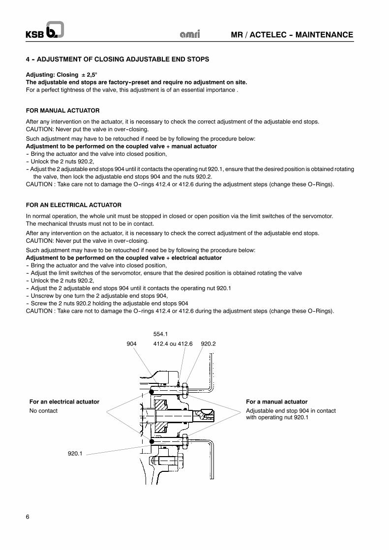
4 -- ADJUSTMENT OF CLOSING ADJUSTABLE END STOPS
Adjusting: Closing ± 2,5°The adjustable end stops are factory--preset and require no adjustment on site.For a perfect tightness of the valve, this adjustment is of an essential importance .
FOR MANUAL ACTUATOR
After any intervention on the actuator, it is necessary to check the correct adjustment of the adjustable end stops.CAUTION: Never put the valve in over--closing.
Such adjustment may have to be retouched if need be by following the procedure below:Adjustment to be performed on the coupled valve + manual actuator-- Bring the actuator and the valve into closed position,-- Unlock the 2 nuts 920.2,-- Adjust the 2 adjustable end stops 904 until it contacts the operating nut 920.1, ensure that the desired position is obtained rotating
the valve, then lock the adjustable end stops 904 and the nuts 920.2.CAUTION : Take care not to damage the O--rings 412.4 or 412.6 during the adjustment steps (change these O--Rings).
FOR AN ELECTRICAL ACTUATOR
In normal operation, the whole unit must be stopped in closed or open position via the limit switches of the servomotor.The mechanical thrusts must not to be in contact.
After any intervention on the actuator, it is necessary to check the correct adjustment of the adjustable end stops.CAUTION: Never put the valve in over--closing.
Such adjustment may have to be retouched if need be by following the procedure below:Adjustment to be performed on the coupled valve + electrical actuator-- Bring the actuator and the valve into closed position,-- Adjust the limit switches of the servomotor, ensure that the desired position is obtained rotating the valve-- Unlock the 2 nuts 920.2,-- Adjust the 2 adjustable end stops 904 until it contacts the operating nut 920.1-- Unscrew by one turn the 2 adjustable end stops 904,-- Screw the 2 nuts 920.2 holding the adjustable end stops 904CAUTION : Take care not to damage the O--rings 412.4 or 412.6 during the adjustment steps (change these O--Rings).
554.1
412.4 ou 412.6 920.2904
For a manual actuator
Adjustable end stop 904 in contactwith operating nut 920.1
For an electrical actuator
No contact
920.1
MR / ACTELEC -- MAINTENANCE
7
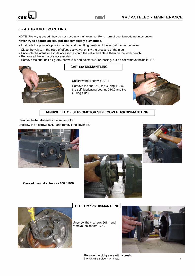
NOTE: Factory greased, they do not need any maintenance. For a normal use, it needs no intervention.
Never try to operate an actuator not completely dismantled.-- First note the pointer’s position or flag and the fitting position of the actuator onto the valve.
-- Close the valve. In the case of offset disc valve, empty the pressure of the pipe.-- Uncouple the actuator and its accessories onto the valve and place them on the work bench-- Remove all the actuator’s accessories-- Remove the sub--unit plug 916, screw 900 and pointer 629 or the flag, but do not remove the balls 486
5 -- ACTUATOR DISMANTLING
Unscrew the 4 screws 901.1
Remove the cap 142, the O--ring 412.5,the self--lubricating bearing 310.2 and theO--ring 412.7
HANDWHEEL OR SERVOMOTOR SIDE: COVER 160 DISMANTLING
Remove the handwheel or the servomotor
Unscrew the 4 screws 901.1 and remove the cover 160
Case of manual actuators 800 / 1600
CAP 142 DISMANTLING
BOTTOM 176 DISMANTLING
Unscrew the 4 screws 901.1 andremove the bottom 176 .
Remove the old grease with a brush.Do not use solvent or a rag.
MR / ACTELEC -- MAINTENANCE
8
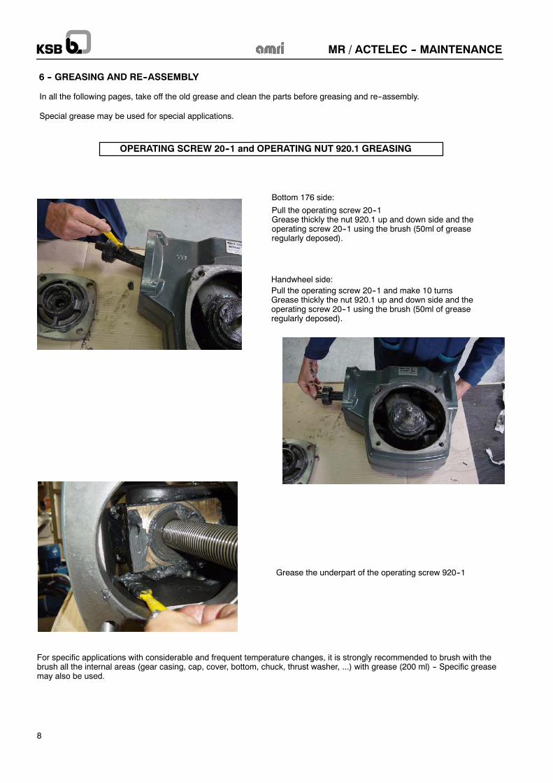
6 -- GREASING AND RE--ASSEMBLY
In all the following pages, take off the old grease and clean the parts before greasing and re--assembly.
Special grease may be used for special applications.
OPERATING SCREW 20--1 and OPERATING NUT 920.1 GREASING
Handwheel side:Pull the operating screw 20--1 and make 10 turnsGrease thickly the nut 920.1 up and down side and theoperating screw 20--1 using the brush (50ml of greaseregularly deposed).
Grease the underpart of the operating screw 920--1
Bottom 176 side:
Pull the operating screw 20--1Grease thickly the nut 920.1 up and down side and theoperating screw 20--1 using the brush (50ml of greaseregularly deposed).
For specific applications with considerable and frequent temperature changes, it is strongly recommended to brush with thebrush all the internal areas (gear casing, cap, cover, bottom, chuck, thrust washer, ...) with grease (200 ml) -- Specific greasemay also be used.

MR / ACTELEC -- MAINTENANCE
9
-- Change the 2 O--rings 412.1 (bottom 176 and cover 160)
-- Grease the O--rings and the grooves
-- Remove the needles thrust 325, Grease them and fit themCAUTION : the counter plates and the rings of the radial roller bearingmust be fitted in the same direction and same order as initial position.
-- Mount the bottom176 and screw it with the screws 900.1
-- Grease all contact areas of the O--rings in the gear casing-- Grease the cylindrical parts of the operating screw 20--1-- Grease the bearing of the bottom 176
PREPARATION OF THE PARTSAll the parts included in the spare parts kit must be used.Only, some O--rings for specific applications can be not used.The O--rings and the bearings must be greased before its fitting (grease defined in the chapter: consumable) (quantity: 100 mlof grease).
BOTTOM 176 SIDE
MR / ACTELEC -- MAINTENANCE
10
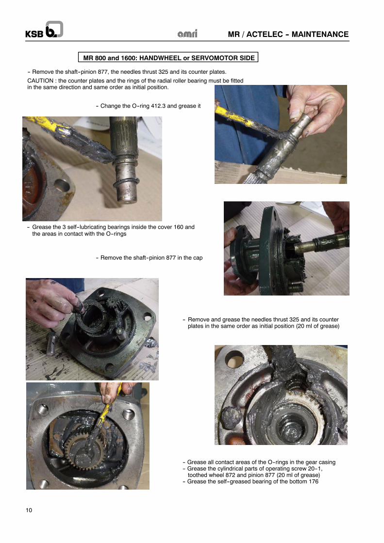
-- Remove the shaft--pinion 877, the needles thrust 325 and its counter plates.
CAUTION : the counter plates and the rings of the radial roller bearing must be fittedin the same direction and same order as initial position.
MR 800 and 1600: HANDWHEEL or SERVOMOTOR SIDE
-- Grease the 3 self--lubricating bearings inside the cover 160 andthe areas in contact with the O--rings
-- Remove and grease the needles thrust 325 and its counterplates in the same order as initial position (20 ml of grease)
-- Change the O--ring 412.3 and grease it
-- Remove the shaft--pinion 877 in the cap
-- Grease all contact areas of the O--rings in the gear casing-- Grease the cylindrical parts of operating screw 20--1,toothed wheel 872 and pinion 877 (20 ml of grease)
-- Grease the self--greased bearing of the bottom 176
MR / ACTELEC -- MAINTENANCE
11
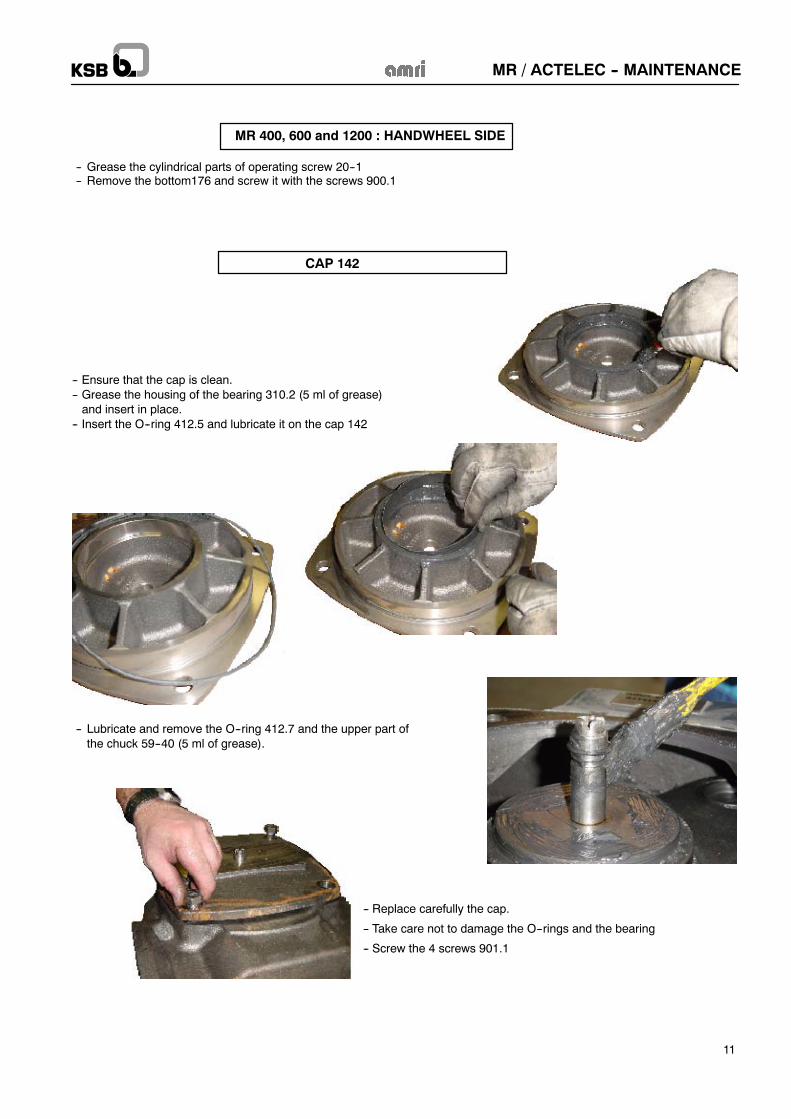
MR 400, 600 and 1200 : HANDWHEEL SIDE
-- Grease the cylindrical parts of operating screw 20--1-- Remove the bottom176 and screw it with the screws 900.1
CAP 142
-- Lubricate and remove the O--ring 412.7 and the upper part ofthe chuck 59--40 (5 ml of grease).
-- Replace carefully the cap.
-- Take care not to damage the O--rings and the bearing
-- Screw the 4 screws 901.1
-- Ensure that the cap is clean.-- Grease the housing of the bearing 310.2 (5 ml of grease)and insert in place.
-- Insert the O--ring 412.5 and lubricate it on the cap 142
MR / ACTELEC -- MAINTENANCE
12
7 -- ACTUATOR/VALVE COUPLING
Fit the pointer 629 and/or the accessories on the actuator in their initial position.
DIRECT FITTING following figure 1 § 3Put some drops of glue on the threads of tie--bolts and screwCover all the area of the base plate Actuator / Valve with flange sealant
or
ADAPTOR FLANGE FITTING following figure 2 § 3Actuator side, cover all the area of the base plate Actuator / Valve with flange sealantFit the flange onto the actuatorPut some drops of glue on the threads of screws and screw themPut some drops of glue on the threads of tie--bolts and screw themValve side, cover all the area of the base plate Actuator / Valve with flange sealant
For a better protection of the actuator, it is recommended to clean, dry and paint all the interfaces after fitting (interfaces gear casing/ bottom, gear casing / cover and gear casing / cap).
-- Couple the actuator onto the valve in its initial position,
-- Check the correct operation of the unit Valve/Manual actuator--Electric actuator / Accessories.
-- If necessary, re--adjust the adjustable end stops: see § 4 Adjustment of closing adjustable end stops.
MR / ACTELEC -- MAINTENANCE
13
8 -- Kit sheets
MR 400 / ACTELEC 200 / ACTELEC 400 Ref. 8507.8400/.--90
MR 600 Ref. 8507.8600/.--90
MR 800 / ACTELEC 500 / ACTELEC 800 Ref. 8507.8800/.--90
MR 1200 Ref. 8507.8120/.--90
MR 1600 / ACTELEC 950 / ACTELEC 1600 Ref. 8507.8160/.--90
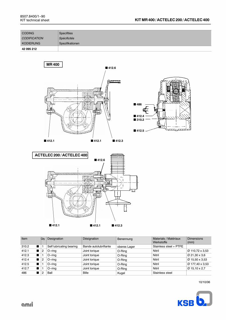
8507.8400/1--90KIT technical sheet KITMR400 / ACTELEC200 / ACTELEC400
CODING
CODIFICATION
KODIERUNG
Specifities
Spécificités
Spezifikationen
42 095 212
ACTELEC200 / ACTELEC400
412.1 412.1 412.3
412.6
412.1
MR400
486
412.4310.2
412.5
412.3412.1
412.6
Item Qty Designation Désignation Benennung Materials / MatériauxWerkstoffe
Dimensions(mm)
310.2 1 Self lubricating bearing Bande autolubrifiante oberes Lager Stainless steel + PTFE
412.1 2 O--ring Joint torique O-Ring Nitril Ø 110,72 x 3,53
412.3 1 O--ring Joint torique O-Ring Nitril Ø 21,30 x 3,6
412.4 2 O--ring Joint torique O-Ring Nitril Ø 15,50 x 3,53
412.5 1 O--ring Joint torique O-Ring Nitril Ø 177,40 x 3,53
412.7 1 O--ring Joint torique O-Ring Nitril Ø 15,10 x 2,7
486 2 Ball Bille Kugel Stainless steel
10/10/06
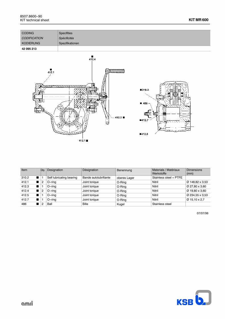
8507.8600--90KIT technical sheet KITMR600
CODING
CODIFICATION
KODIERUNG
Specifities
Spécificités
Spezifikationen
42 095 213
Item Qty Designation Désignation Benennung Materials / MatériauxWerkstoffe
Dimensions(mm)
310.2 1 Self lubricating bearing Bande autolubrifiante oberes Lager Stainless steel + PTFE
412.1 2 O--ring Joint torique O-Ring Nitril Ø 148,82 x 3,53
412.3 1 O--ring Joint torique O-Ring Nitril Ø 27,80 x 3,60
412.4 2 O--ring Joint torique O-Ring Nitril Ø 19,80 x 3,60
412.5 1 O--ring Joint torique O-Ring Nitril Ø 234,55 x 3,53
412.7 1 O--ring Joint torique O-Ring Nitril Ø 15,10 x 2,7
486 2 Ball Bille Kugel Stainless steel
07/07/06
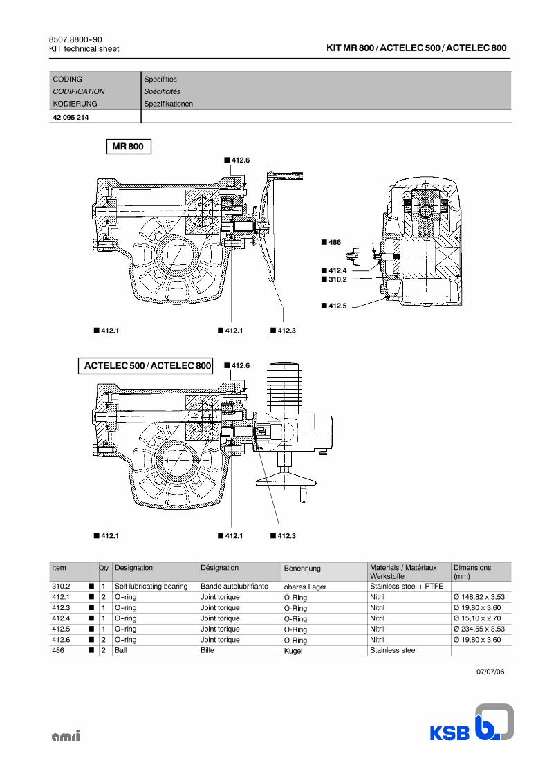
8507.8800--90KIT technical sheet KITMR800 / ACTELEC500 / ACTELEC800
CODING
CODIFICATION
KODIERUNG
Specifities
Spécificités
Spezifikationen
42 095 214
412.1 412.1 412.3
412.6
MR800
486
412.4310.2
412.5
412.1412.1 412.3
412.6ACTELEC500 / ACTELEC800
Item Qty Designation Désignation Benennung Materials / MatériauxWerkstoffe
Dimensions(mm)
310.2 1 Self lubricating bearing Bande autolubrifiante oberes Lager Stainless steel + PTFE
412.1 2 O--ring Joint torique O-Ring Nitril Ø 148,82 x 3,53
412.3 1 O--ring Joint torique O-Ring Nitril Ø 19,80 x 3,60
412.4 1 O--ring Joint torique O-Ring Nitril Ø 15,10 x 2,70
412.5 1 O--ring Joint torique O-Ring Nitril Ø 234,55 x 3,53
412.6 2 O--ring Joint torique O-Ring Nitril Ø 19,80 x 3,60
486 2 Ball Bille Kugel Stainless steel
07/07/06
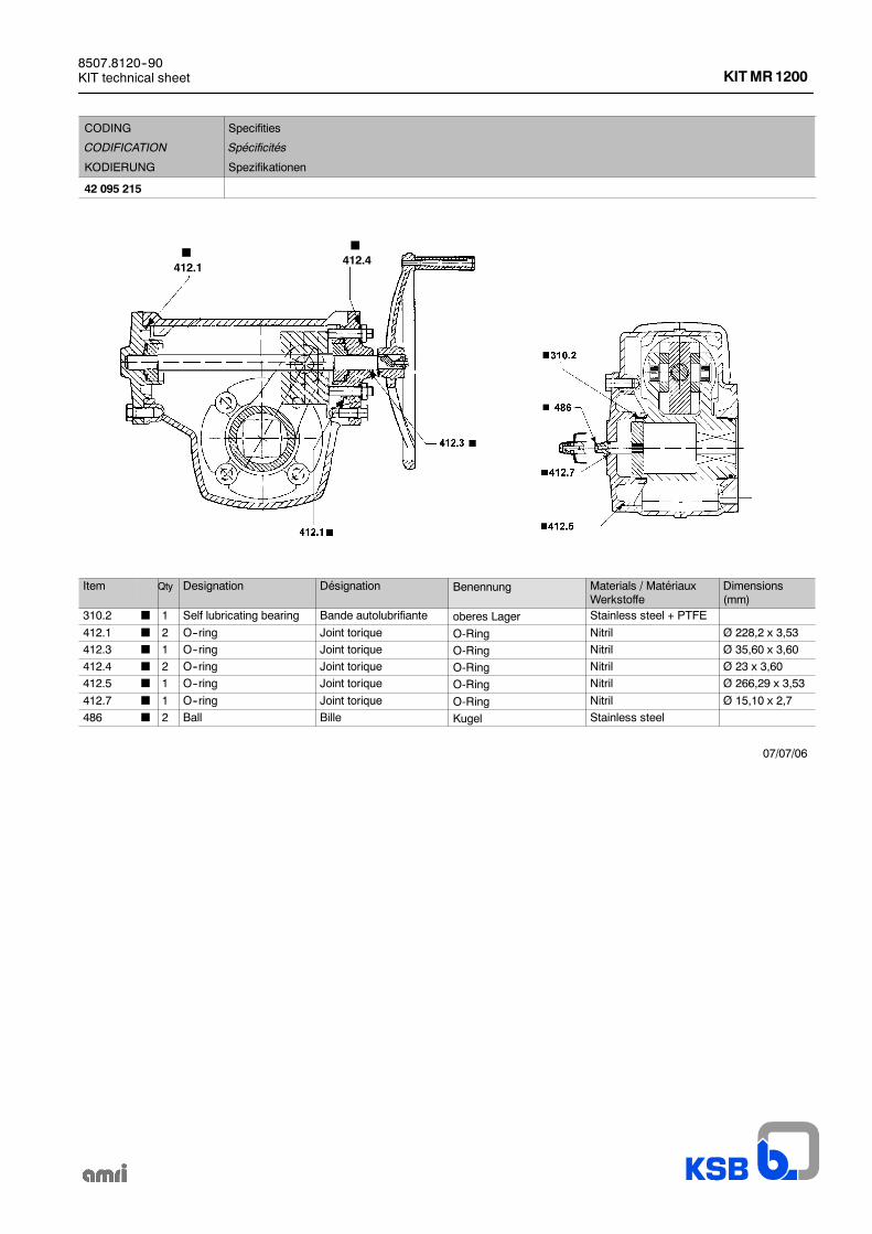
8507.8120--90KIT technical sheet KITMR1200
CODING
CODIFICATION
KODIERUNG
Specifities
Spécificités
Spezifikationen
42 095 215
412.4412.1
Item Qty Designation Désignation Benennung Materials / MatériauxWerkstoffe
Dimensions(mm)
310.2 1 Self lubricating bearing Bande autolubrifiante oberes Lager Stainless steel + PTFE
412.1 2 O--ring Joint torique O-Ring Nitril Ø 228,2 x 3,53
412.3 1 O--ring Joint torique O-Ring Nitril Ø 35,60 x 3,60
412.4 2 O--ring Joint torique O-Ring Nitril Ø 23 x 3,60
412.5 1 O--ring Joint torique O-Ring Nitril Ø 266,29 x 3,53
412.7 1 O--ring Joint torique O-Ring Nitril Ø 15,10 x 2,7
486 2 Ball Bille Kugel Stainless steel
07/07/06

8507.8160--90KIT technical sheet KITMR1600 / ACTELEC950 / ACTELEC1600
CODING
CODIFICATION
KODIERUNG
Specifities
Spécificités
Spezifikationen
42 095 216
412.1 412.1 412.3
412.6
MR1600
412.3412.1412.1
486
412.4310.2
412.5
412.6ACTELEC950 / ACTELEC1600
Item Qty Designation Désignation Benennung Materials / MatériauxWerkstoffe
Dimensions(mm)
310.2 1 Self lubricating bearing Bande autolubrifiante oberes Lager Stainless steel + PTFE
412.1 2 O--ring Joint torique O-Ring Nitril Ø 221,85 x 3,53
412.3 1 O--ring Joint torique O-Ring Nitril Ø 21,30 x 3,60
412.4 1 O--ring Joint torique O-Ring Nitril Ø 15,10 x 2,70
412.5 1 O--ring Joint torique O-Ring Nitril Ø 266,29 x 3,53
412.6 2 O--ring Joint torique O-Ring Nitril Ø 23,00 x 3,60
486 2 Ball Bille Kugel Stainless steel
07/07/06
MR / ACTELEC -- MAINTENANCE
18
Notes
KSB S.A.S4, allée des Barbanniers • 92635 Gennevilliers Cedex (France)Tél. : +33 1 41 47 75 00 • Fax : +33 1 41 47 75 10 • www.ksb.fr
MR / ACTELEC -- MAINTENANCE
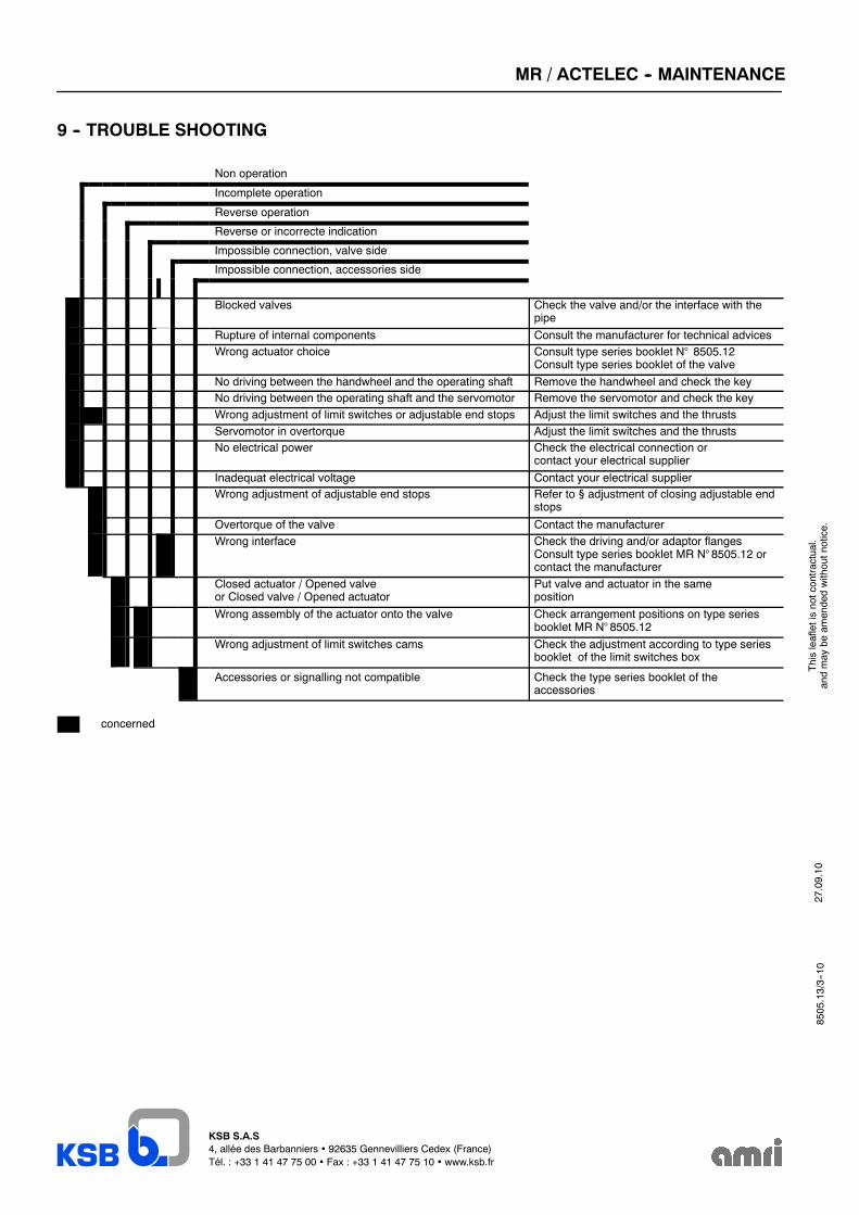
9 -- TROUBLE SHOOTING
Non operation
Incomplete operation
Reverse operation
Reverse or incorrecte indication
Impossible connection, valve side
Impossible connection, accessories side
Blocked valves Check the valve and/or the interface with thepipe
Rupture of internal components Consult the manufacturer for technical advicesWrong actuator choice Consult type series booklet N° 8505.12
Consult type series booklet of the valve
No driving between the handwheel and the operating shaft Remove the handwheel and check the keyNo driving between the operating shaft and the servomotor Remove the servomotor and check the keyWrong adjustment of limit switches or adjustable end stops Adjust the limit switches and the thrustsServomotor in overtorque Adjust the limit switches and the thrustsNo electrical power Check the electrical connection or
contact your electrical supplier
Inadequat electrical voltage Contact your electrical supplierWrong adjustment of adjustable end stops Refer to § adjustment of closing adjustable end
stops
Overtorque of the valve Contact the manufacturerWrong interface Check the driving and/or adaptor flanges
Consult type series booklet MR N° 8505.12 orcontact the manufacturer
Closed actuator / Opened valveor Closed valve / Opened actuator
Put valve and actuator in the sameposition
Wrong assembly of the actuator onto the valve Check arrangement positions on type seriesbooklet MR N° 8505.12
Wrong adjustment of limit switches cams Check the adjustment according to type seriesbooklet of the limit switches box
Accessories or signalling not compatible Check the type series booklet of theaccessories
concerned
27.09.10
Thisleafletisnotcontractual.
andmay
beam
endedwithoutnotice.
8505.13/3--10