Embed Size (px)
Citation preview

I
r J
DIGITAL EQUIPMENT CORPORATION
... dedicated to the future of Graphic Arts
typeset-8 systemspositive logic maintenance manual
lil I. L.--------mD~DDmD------.-...J ~-.
•
DIGITAL EQUIPMENT CORPORATION
... dedicated to the future of Graphic Arts
typeset-8 systemspositive logic maintenance manual
~-----~DmDDmD--------I "
')
DIGITAL EQUIPMENT CORPORATION
... dedicated to the future of Graphic Arts
typeset-8 systemspositive logic maintenance manual
'---------~D~DDmD--------J
DIGITAL EQUIPMENT CORPORATION
... dedicated to the future of Graphic Arts
typeset-8 systemspositive logic maintenance manual
L---------~D~DDmD--------I
..
DIGITAL EQUIPMENT CORPORATION
... dedicated to the future of Graphic Arts
typeset-8 systemspositive logic maintenance manual
~-----~DmDDmD--------I . "

~)
)
typeset-8 systemspositive logic maintenance manual
DEC-08-HMMPA-A-D
digital equipment corporation • maynard. massachusetts
1 st Edition October 1972
Copyright © 1972 by Digital Equipment Corporation
The materi!!, in t"'i~ manual i$ for inf()rmation;II purl;l0ses and is subject to change without notiCl!. '
The folloWing are trademarks I;>f D~ital Equipment
Corporation, Maynar\i, Maf$~achusetts:
DEC
FLIP CHIP DIGITAL
PIDP
FOCAL COMPUTER LAB
CONTENTS
CHAPTER 1 INTRODUCTION
1.1 1.2
System Description Specifications . .
CHAPTER 2 INSTALLATION
2.1 2.2 2.3
Cabling and Terminations Power Connections .. Installation Verification
CHAPTER 3 OPERATION AND PROGRAMMING
3.1 3.2 3.3 3.3.1 3.3.2 3.3.3 3.3.4 3.3.5
Program Instructions Data Formats .... Controls and Indicators PR68B High-Speed Paper-Tape Reader PR68D High-Speed Paper-Tape Reader PR68DA High-Speed Paper-Tape Reader PA63 Multiple Reader/Punch Control and Interface Unit PP67C/D High-Speed Paper-Tape Punch ....... .
CHAPTER 4 THEORY OF OPERATION
4.1 4.1.1 4.1.2 4.1.3 4.1.4 4.1.5 4.1.6 4.1.7 4.2 4.2.1 4.2.2 4.2.3 4.2.4 4.2.5 4.3 4.4 4.4.1 4.4.2 4.4.3 4.5 4.6 4.6.1 4.6.2
PA63 Multiple Reader/Punch Control and Interface Unit Power Up ........... . lOT Decoder for Reader Control Reader Selection ...... . Tape Reading ........ . lOT Decoder for Punch Control Punch Seletion Tape Punching ....... . PA68F Single Reader/Punch Control and Interface Unit PowerUp ........... . lOT Decoder for Reader Control Tape Reading ........ . lOT Decoder for Punch Control Tape Punching ....... . PR68B High-Speed Paper-Tape Reader PR68D High-Speed Paper-Tape Reader Tape Transport Mechanism Photoelectric Tape Reader ..... . NTT A Reader Selection . . . . . . PR68DA High-Speed Paper-Tape Reader PP67C/D High-Speed Paper-Tape Punch Motor Control Solenoid Control
iii
Page
1-2 1-3
2-1 2-5 2-5
3-1 3-1 3-3 3-3 3-4 3-5 3-5 3-7
4-1 4-2 4-2 4-2 4-3 4-5 4-6 4-6 4-8 4-8 4-8 4-9
4-11 4-12 4-13 4-13 4-15 4-15 4-15 4-16 4-16 4-17 4-18
CONTENTS (Cont)
Page
CHAPTERS ADJUSTMENTS
5.1 M401 Reader Clock · ......... 5-1 5.2 M710 Punch Control ......... 5-1
5.3 PR68B High-Speed Paper-Tape Reader 5-4 5.3.1 Static Adjustment · ......... 5-6 5.3.2 Dynamic Adjustment ......... 5-9 5.4 PR68D/DA High-Speed Paper-Tape Reader 5-10 5.4.1 Tape Guide ........ 5-12 5.4.2 Tape Level Slide G ~ • • • • • • • • 5-12 5.4.3 Lamp Selection and Voltage 5-12 5.4.4 Sprocket Wheel and Condensing Lens 5-13 5.4.5 G918 Amplifier Adjustment 5-14 5.5 PP67C/D High-Speed Paper-Tape Punch 5-16 5.5.1 Punch Mechanism Adjustment 5-16 5.5.2 Low Tape Adjustment 5-17 5.6 4 ms Change Reader Delay 5-18 5.7 I Second Change Punch Delay 5-19 5.8 Mixed Tape Levels · ..... 5-20
CHAPTER 6 MAINTENANCE
6.1 Test Equipment and Diagnostic Programs 6-1 6.2 Preventive Maintenance 6-3 6.3 Spare Parts ....... . . . . . . . . 6-3
APPENDIX A GLOSSARY OF TERMS
APPENDIX B ENGINEERING DRAWINGS
B.I Engineering Drawings ...... , . . . . . . . . .. B-1
Figure No.
I-I 1-2 1-3 2-1 2-2 2-3 2-4 2·5 3-1 3-2 3-3 3-4 3-5 4-1
ILLUSTRATIONS
Title
Typeset-8 System - Positive Logic Multiple Reader/Punch System .. Single Reader/Punch System PR68B Reader/Interface Cable Interconnection PR68D/DA Reader/Interface Cable Interconnection PP67C/D Punch/Interface Cable Interconnection M978 Connector Module M979 Connector Module Paper-Tape Formats PR68B Reader .... . PR68D/DA Reader .. . PA63 Multiple Reader/Punch Control PP67C/D Punch Controls ..... . Tape Reader Timing Sequence for PA63
iv
Page
I-I 1-2 1-3 2-2 2-3 2-4 2-4 2-5 3-2 3-3 3-4 3·5 3-7 4-3
-~,
-~
Figure No.
4-2 4-3 4-4 4-5 4-6 4-7 4-8 4-9 5-1 5-2 5-3 5-4 5-5 5-6 5-7 5-8 5-9 5-10 5-11
5-12 5-13 5-14 5-15 5-16 5-17 5-18 5-19
Table No.
I-I 1-2 1-3 1-4 1-5 2-1 3-1 3-2 3-3 3-4 3-5 3-6 6-1 6-2 6-3 6-4 6-5
ILLUSTRATIONS (Cont)
Title
Tape Punch Timing Sequence for PA63 ........ . M710 Punch Control for PA63, Simplified Logic Diagram Tape Reader Timing Sequence for PA68F ....... . Tape Punch Timing Sequence for PA68F ........ . M710 Punch Control for PA68F, Simplified Logic Diagram G930 Nontom Tape Alloting Module, Simplified Logic Diagram Punch Motor Control, Simplified Functional Diagram Punch Solenoid Control, Simplified Functional Diagram M401 Reader Clock Adjustment Location Clock Pulse Waveform M710 Punch Control Adjustment Location Punch Done Pulse Waveform ...... . PR68B Reader Adjustment Location .. . 6-Level Guide and Reader Head Adjustment Reader Lamp and Condensing Lens Adjustment Lateral Adjustment of Sprocket Wheel Axial Adjustment of Sprocket Wheel ..... . Spring Arm Adjustment for PR68B . . . . . . .
, .
Relationship of PR68B Reader Data Pulse and Strobe Pulse for PA63 and PA68F ................... . PR68D/DA Reader Adjustment Location ...... . Relationship of Data Hole and Photocell for PR68D/DA , Spring Arm Adjustment for PR68D/DA ....... . Relationship ofPR68D/DA Reader Data and Strobe Pulse Punch Solenoid Waveform ..... . M302 Dual Delay Multivibrator Module Change Reader Delay Waveform Change Punch Delay Waveform ...
P A 63 S pecifica tions PA68F Specifications PR68B Specifications
TABLES
Title
PR68D/DA Reader Specifications PP67C/D Punch Specifications Reader and Punch Cables ... . Program Instructions ..... . PR68B Reader, Control and Indicator PR68D Reader, Control and Indicator PR68DA Reader, Control and Indicator PA63 Reader/Punch Control, Controls and Indicators PP67C/D Punch, Controls Test Equipment and Tools Diagnostic Programs Typesetting Configuration Test Programs System Exerciser Overlays Typesetting Spares
v
\
..
Page
4-5 4-7 4-9
4-11 4-12 4-14 4-17 4-19
5-2 5-2 5-3 5-3 5-4 5-6 5-7 5-7 5-8 5-8
5-9 5-10 ~-13
5-14 5-16 5-17 5-19 5-19 5-20
Page
1-4 1-4 1-5 1-5 1-6 2-2 3-1 3-3 3.4-3-5 3-6 3-8 6-1 6-1 6-2 6-3 6-4

Figure No.
6-6 B-1
TABLES (Cont)
Title
Parts List For PR68B ... Index of Master Drawing Lists
vi
Page
6-5 . B-1
, )' ',-
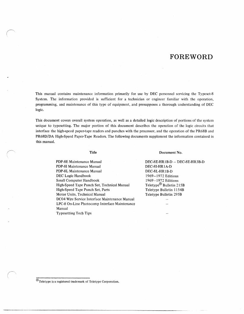
FOREWORD
This manual contains maintenance information primarily for use by DEC personnel servicing the Typeset-S
System. The information provided is sufficient for a technician or engineer familiar with the operation,
programming, and maintenance of this type of equipment, and presupposes a thorough understanding of DEC
logic.
This document covers overall system operation, as well as a detailed logic description of portions of the system
unique to typesetting. The major portion of this document describes the operation of the logic circuits that
interface the high-speed paper-tape reilders and punches with the processor, and the operation of the PR6SB and
RR6SD/DA High.-Spyed Paper.Tape Readers. The following documents supplement the information contained in this manual.
Title
PDP.8E Maintenance Manual PDP-SI Maintenance Manual PDP-8L Maintenance Manual DEC Logic Handbook Small Computer Handbook High-Speed Tflpe Punch Set, Technical Manual High-Speed Tape Punch Set, Parts Motor Units, Technical Manual DC04 Wire Service Interface Maintenance Manual LPC-S On.Line Photocomp Interface Maintenance Manual Typesetting Tech Tips
®Teletype i~ a registered trademark of Teletype Corporation.
Document No.
DEC.SE-HRIB-D ~ DEC-8E-HR3B-D DEC-SI-HR I A-D DEC-8L-HR I B-D 1969 ~ 1972 Editions 1969-1972 Editions Teletype® Bulletin 215B Teletype Bulletin 1154B Teletype Bulletin 295B

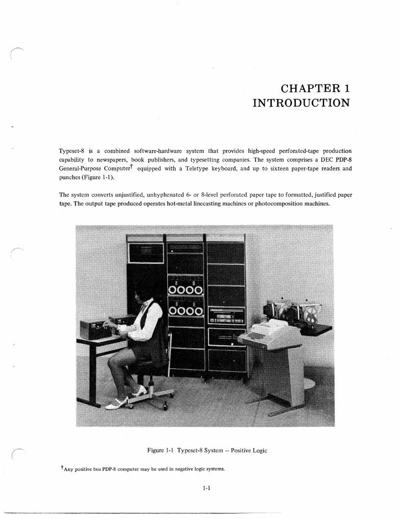
CHAPTER 1 INTRODUCTION
Typeset-8 is a combined software-hardware system that provides high-speed perforated-tape production
capability to newspapers, book publishers, and typesetting companies. The system comprises a DEC PDP-8
General-Purpose Computert equipped with a Teletype keyboard, and up to sixteen paper-tape readers and
punches (Figure 1-1).
The system converts unjustified, unhyphenated 6- or 8-level perforated paper tape to formatted, justified paper
tape. The output tape produced operates hot-metal line casting machines or photocomposition machines.
Figure 1-1 Typeset-8 System - Positive Logic
t Any positive bus PDP-8 computer may be used in negative logic systems.
1-1
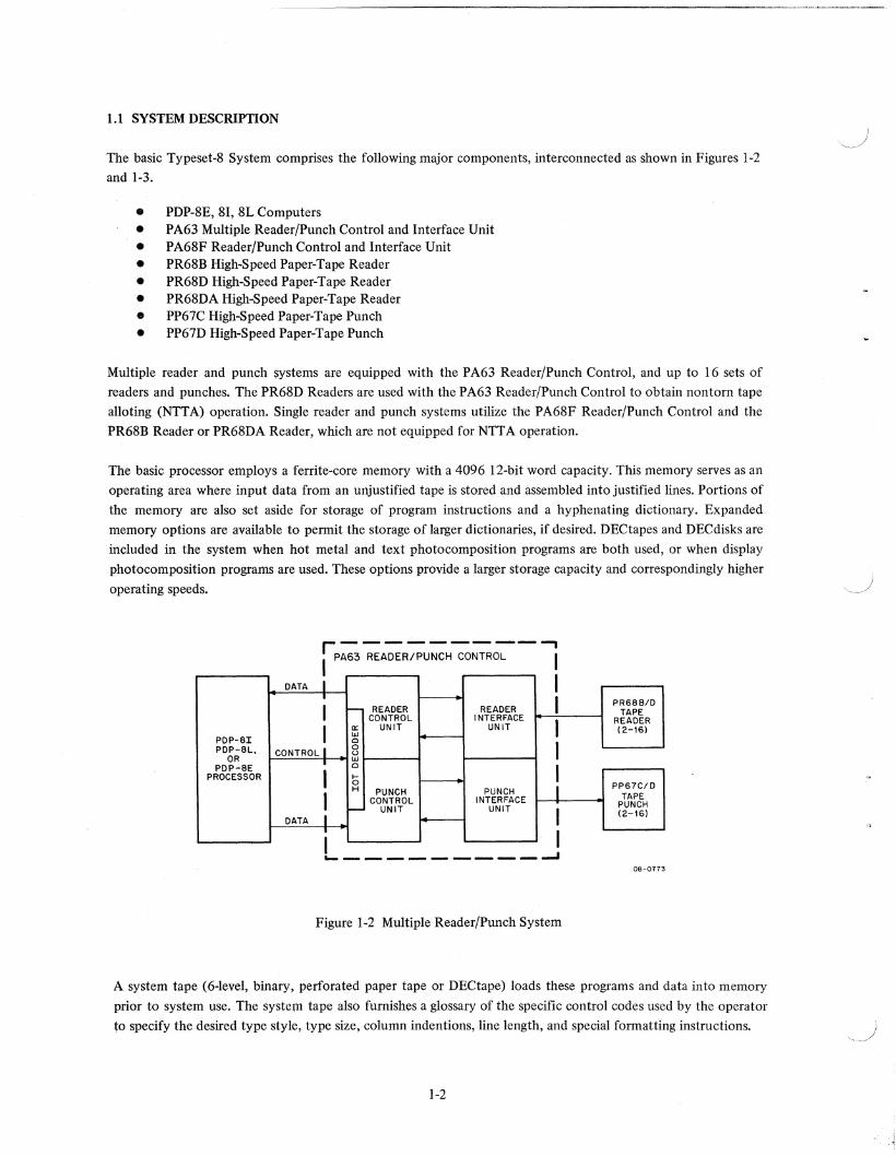
1.1 SYSTEM DESCRIPTION
The basic Typeset-8 System comprises the following major components, interconnected as shown in Figures 1-2 and 1-3.
• PDP-8E, 81, 8L Computers • PA63 Multiple Reader/Punch Control and Interface Unit • PA68F Reader/Punch Control and Interface Unit • PR68B High-Speed Paper-Tape Reader • PR68D High-Speed Paper-Tape Reader • PR68DA High-Speed Paper-Tape Reader • PP67C High-Speed Paper-Tape Punch • PP67D High-Speed Paper-Tape Punch
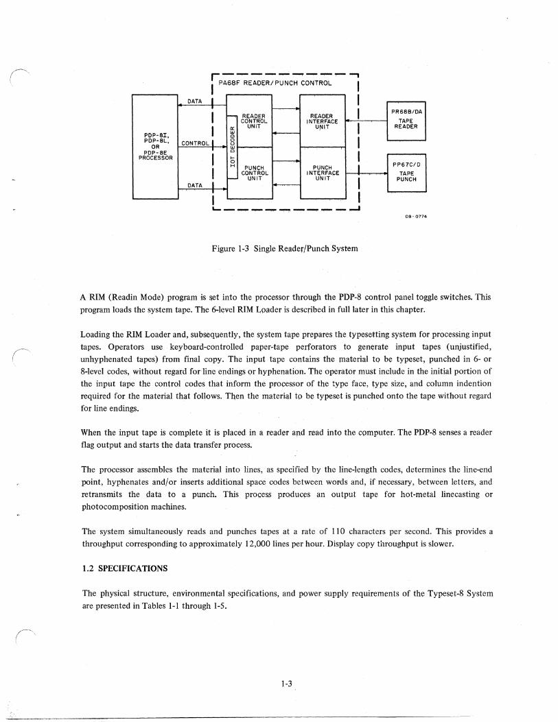
Multiple reader and punch systems are equipped with the PA63 Reader/Punch Control, and up to 16 sets of
readers and punches. The PR68D Readers are used with the P A63 Reader/Punch Control to obtain non torn tape alloting (NTT A) operation. Single reader and punch systems utilize the P A68F Reader/Punch Control and the PR68B Reader or PR68DA Reader, which are not equipped for NTTA operation.
The basic processor employs a ferrite-core memory with a 4096 12-bit word capacity. This memory serves as an
operating area where input data from an unjustified tape is stored and assembled into justified lines. Portions of the memory are also set aside for storage of program instructions and a hyphenating dictionary. Expanded
memory options are available to pennit the storage of larger dictionaries, if desired. DECtapes and DEC disks are included in the system when hot metal and text photocomposition programs are both used, or when display
photocomposition programs are used. These options provide a larger storage capacity and correspondingly higher
operating speeds.
DATA I I • I PR6BB/D I - READER READER TAPE CONTROL INTERFACE
I READER
I a: UNIT UNIT (2-16) .... PDP-BI 0
I PDP-BL, CONTROL I 0 u
OR .... PDP-BE • 0
I PROCESSOR I ~ 0
I PP67C/D H PUNCH PUNCH
I CONTROL INTERFACE TAPE PUNCH r- UNIT UNIT I (2-161
DATA I • I I ~---..------.....I 08-0773
Figure 1-2 Multiple Reader/Punch System
A system tape (6-level, binary, perforated paper tape or DECtape) loads these programs and data into memory
prior to system use. The system tape also furnishes a glossary of the specific control codes used by the operator to specify the desired type style, type size, column indentions, line length, and special fonnatting instructions.
1-2
DATA I I i ....., READER READER I PR6SB/DA
CONTROL. INTERFACE
I TAPE
I Q: UNIT UjlJlT READER I<J PDP'SI, 0
PDp·8L., CONTROL. I 8 I OR w PDP-SE 0
I PROCESSOR I f-0 H PUNCH PUNCH I PP61'C/D
I CONTROL. INTE;RFACE TAPE I- IINIT UNIT I PUNCH
DATA I •
08 - 0774
Figure 1-3 Single Reader/Punch System
A RIM (Readin Mode) program is set into the processor through the PDP-S control panel toggle switches. This
program loads the system tape. The 6-level RIM Loader is described in full later in this chapter.
Loading the RIM Loader and, subsequently, the system tape prepares the typesettin~ system for processing input
tapes. Operators use keyboard-controlled paper-tape perforators to generate input tapes (unjustified,
unhyphenated tapes) from final copy. The input tape contains the material tq be typeset, punched in 6- or
8-level codes, without regard forline endings or hyphenation. The operator must include in the initial portion of
the input tape the control codes that inform the processor of the type face, type size, and column indention
required for the material that follows. Then the material to be typeset is punched onto the tape without regard
for line endings.
When the input tape is complete it is placed in a reader and read into the computer. The PDP-8 senses a reader
flag output and starts the data transfer process.
The processor assembles the material into lines, as specified by the line-length codes, determines the line-end
point, hyphenates and/or inserts additional space codes between words and, if necessary, between letters, and
retransmits the data to a punch. This process produces ;m output tape for hot-metal line casting or
photocomposition machines.
The system simultaneously reads and punches tapes at a rate of 110 characters per second. This provides a
throughput corresponding to approximately 12,000 lines per hour. Display copy throughput is slower.
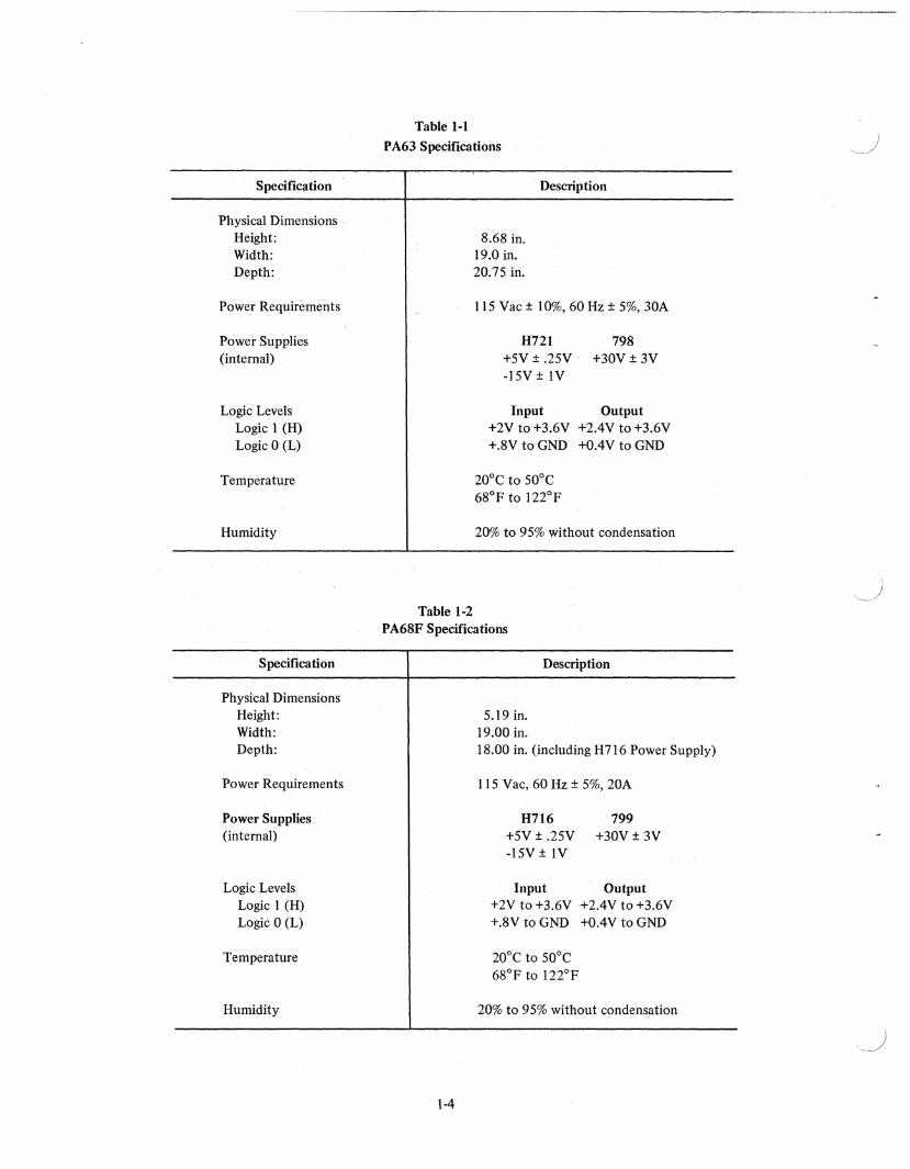
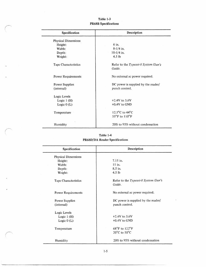
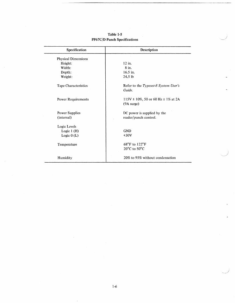
1.2 SPECIFICATIONS
The physical structure, environmental specifications, and power supply requirements of the Typeset-8 System
are presented in Tables 1-1 through 1-5.
1-3
Specification
Physical Dimensions . Height: Width: Depth:
Power Requirements
Power Supplies (internal)
Logic Levels Logic 1 (H) Logic 0 (L)
Temperature
Humidity
Specification
Physical Dimensions Height: Width: Depth:
Power Requirements
Power Supplies (internal)
Logic Levels Logic 1 (H) Logic 0 (L)
Temperature
Humidity
Table 1-1
PA63 Specifications
8.68 in. 19.0 in. 20.75 in.
Description
115 Vac ± 10%,60 Hz ± 5%, 30A
H721 798 +5V ± .25V +30V ± 3V -15V ± IV
Input Output +2V to +3.6V +2AV to +3.6V +.8V to GND +OAV to GND
200 e to 500 e 68°p to 122°p
20% to 95% without condensation
Table 1-2 PA68P Specifications
1-4
5.19 in. 19.00 in.
Description
18.00 in. (including H716 Power Supply)
115 Vac, 60 Hz ± 5%, 20A
H716 799 +5V ± .25V +30V ± 3V -15V ± IV
Input Output +2V to +3.6V +2AV to +3.6V +.8V to GND +OAV to GND
200 e to 500 e 68°p to 122°p
20% to 95% without condensation
)
Specification
Physical Dimensions Height: Width: Depth: Weight:
Tape Characteristics
Power Requirements
Power Supplies (internal)
Logic Levels Logic 1 (H) Logic 0 (L)
Temperature
Humidity
Specification
Physical Dimensions Height: Width: Depth: Weight:
Tape Characteristics
Power Requirements
Power Supplies (internal)
Logic Levels Logic 1 (H) Logic 0 (L)
Temperature
Humidity
Table 1-3
PR68B Specifications
Table 1-4
6 in. 8-1/4 in.
10-1/4 in. 4.S1b
Description
Refer to the Typeset-8 System User's Guide.
No external ac power required.
DC power is supplied by the reader/ punch control.
+2AV to 3.6V +OAV to GND
12.S0C to 44°C SSoF to 110°F
20% to 9S% without condensation
PR68DjDA Reader Specifications
l-S
7.1S in. 11 in. 8.S in. 4.S1b
Description
Refer to the Typeset-8 System User's Guide.
No external ac power required.
DC power is supplied by the reader/ punch control.
+2AV to 3.6V +OAV to GND
68°F to 122°F 20°C to SO°C
20% to 9S% without condensation
Specification
Physical Dimensions Height: Width: Depth: Weight:
Tape Characteristics
Power Requirements
Power Supplies (internal)
Logic Levels Logic I (H) Logic 0 (L)
Temperature
Humidity
Table 1-5
PP67C/D Punch Specifications
1-6
12 in. 8 in.
16.5 in. 24.Slb
Description
Refer to the Typeset-8 System User's GUide.
115V ± 10%, 50 or 60 Hz ± I % at 2A (9A surge)
DC power is supplied by the reader/punch control.
GND +30V
68°F to 122°F 20°C to 50°C
20% to 95% without condensation
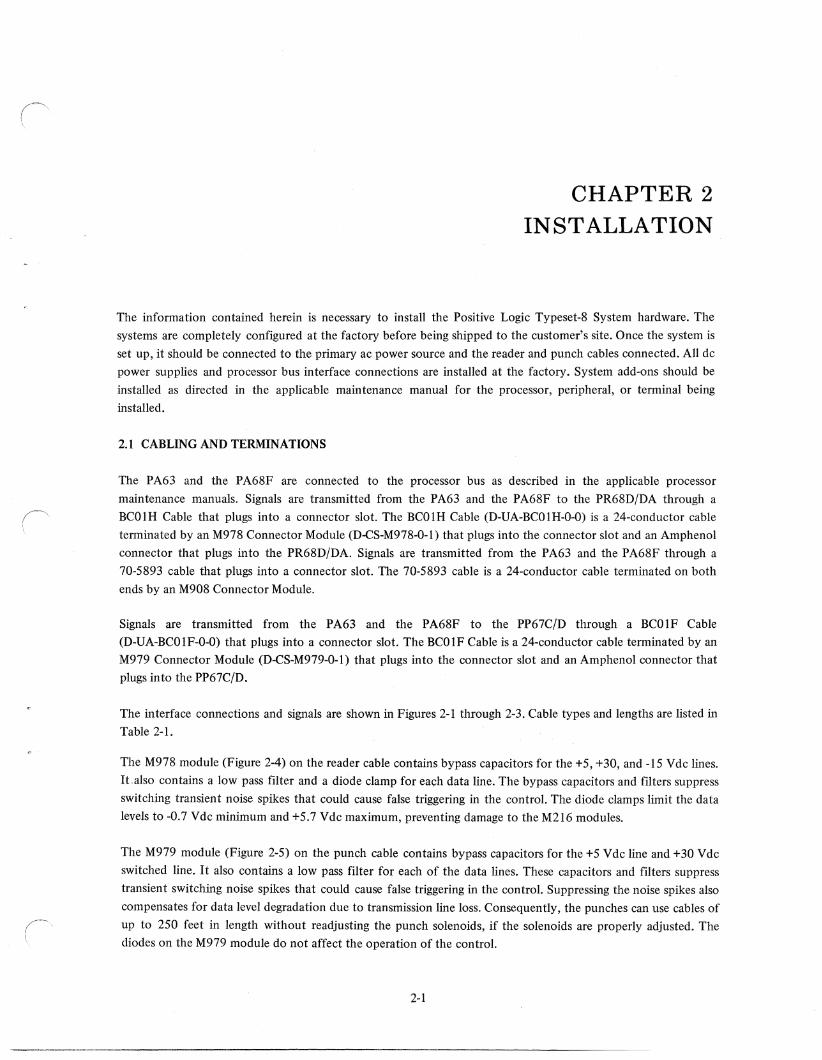
CHAPTER 2 INSTALLATION
The infonnation contained herein is necessary to install the Positive Logic Typeset-8 System hardware. The systems are completely configured at the factory before being shipped to the customer's site. Once the system is
set up, it should be connected to the primary ac power source and the reader and punch cables connected. All dc
power supplies and processor bus interface connections are installed at the factory. System add-ons should be
installed as directed in the applicable maintenance manual for the processor, peripheral, or tenninal being
installed.
2.1 CABLING AND TERMINATIONS
The P A63 and the P A68F are connected to the processor bus as described in the applicable processor
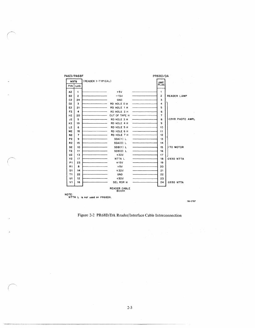
maintenance manuals. Signals are transmitted from the PA63 and the PA68F to the PR68D/DA through a BCOIH Cable that plugs into a connector slot. The BCOIH Cable (D-UA-BCOIH-O-O) is a 24-conductor cable tenninated by an M978 Connector Module (D..cS-M978-0-1) that plugs into the connector slot and an Amphenol
connector that plugs into the PR68D/DA. Signals are transmitted from the PA63 and the PA68F through a
70-5893 cable that plugs into a connector slot. The 70-5893 cable is a 24-conductor cable terminated on both
ends by an M908 Connector Module.
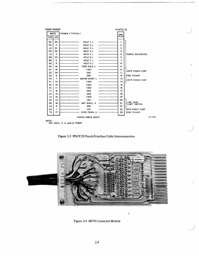
Signals are transmitted from the PA63 and the PA68F to the PP67C/D through a BC01F Cable (D-UA-BC01F-0-0) that plugs into a connector slot. The BC01F Cable is a 24-conductor cable tenninated by an M979 Connector Module (D..cS-M979-0-1) that plugs into the connector slot and an Amphenol connector that plugs into the PP67C/D.
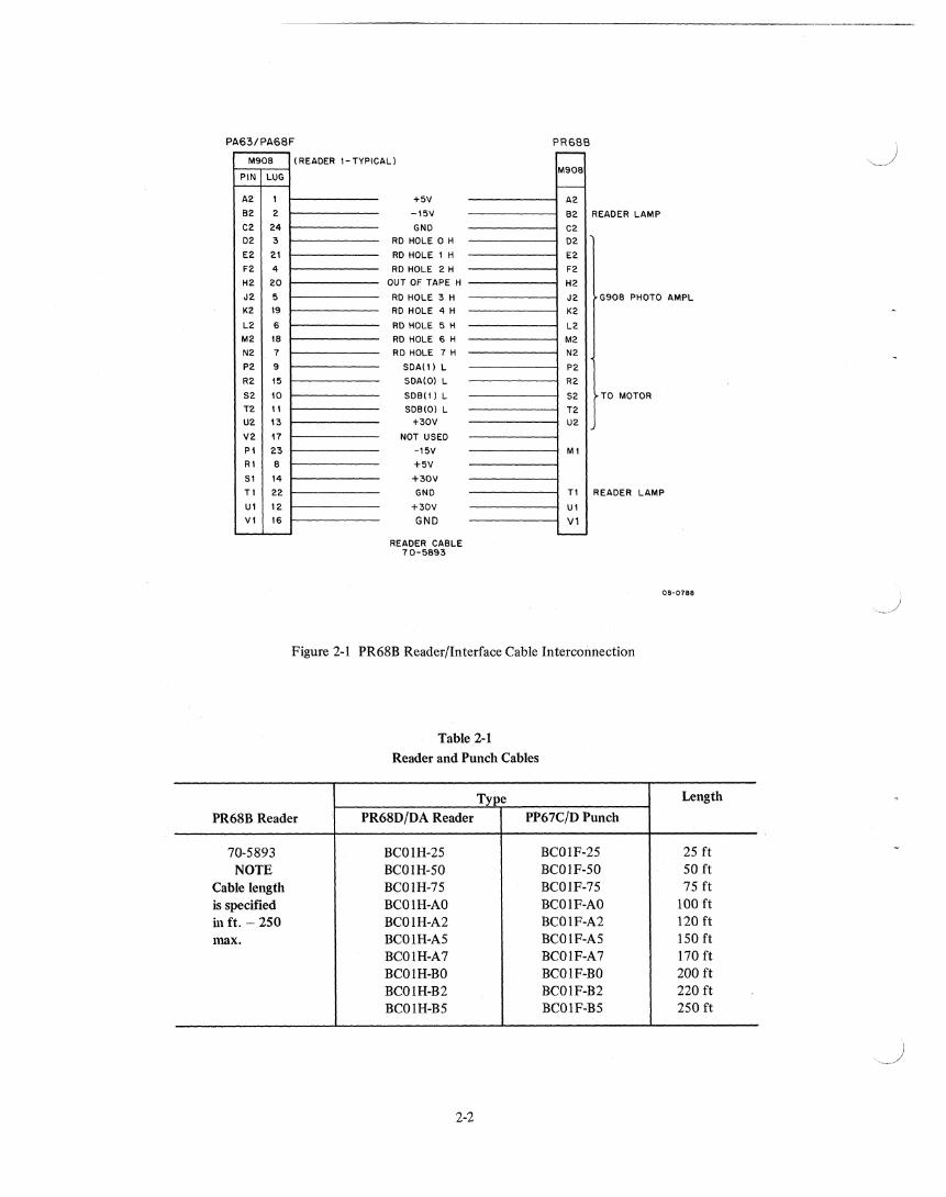
The interface connections and signals are shown in Figures 2-1 through 2-3. Cable types and lengths are listed in
Table 2-1.
The M978 module (Figure 2-4) on the reader cable contains bypass capacitors for the +5, +30, and -IS Vdc lines. It ,also contains a low pass filter and a diode clamp for each data line. The bypass capacitors and filters suppress
switching transient noise spikes that could cause false triggering in the control. The diode clamps limit the data levels to -0.7 Vdc minimum and +5.7 Vdc maximum, preventing damage to the M216 modules.
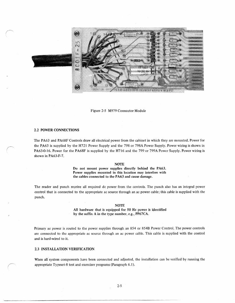
The M979 module (Figure 2-5) on the punch cable contains bypass capacitors for the +5 Vdc line and +30 Vdc
switched line. It also contains a low pass filter for each of the data lines. These capacitors and filters suppress transient switching noise spikes that could cause false triggering in the control. Suppressing the noise spikes also
compensates for data level degradation due to transmission line loss. Consequently, the punches can use cables of up to 250 feet in length without readjusting the punch solenoids, if the solenoids are properly adjusted. The diodes on the M979 module do not affect the operation of the control.
2-1
PA63/PA68F
M908 (READER I-TYPIC
PIN LUG
A2 I
B2 2
C2 24
02 3
E2 21
F2 4
H2 20
J2 5
K2 19
L2 6
M2 18
N2 7
P2 9
R2 15
52 10
T2 \I
U2 13
V2 17
PI 23
Rl 8
51 14
TI 22
Ul 12
VI 16
AL)
+5V
-15V
GND
RD HOLE 0 H
RD HOLE I H
RD HOLE 2 H
OUT OF TAPE H
RO HOLE 3 H
RO HOLE 4 H
RD HOLE 5 H
RD HOLE 6 H
RD HOLE 7 H
5DA(1l L
5DA(0) L
5DB(I) L
5DB(0) L
+30V
NOT U5ED
-15V
+5V
+30V
GNO
+30V
GND
READER CA8LE 70-5893
PR68B r--
M908
f.--A2
82 R EADER LAMP
C2
02
E2
F2
H2
J2 G908 PHOTO AMPL
K2
L2
M2
N2
P2
R2
52 TO MOTOR
T2 U2
Ml
T1 R EADER LAMP
Ul
Vl '---
08-0788
Figure 2-1 PR68B Reader/Interface Cable Interconnection
Table 2-1
Reader and Punch Cables
Type Length
PR68B Reader PR68D/DA Reader PP67C!D Punch
70-5893 BCOlH-25 BCOIF-25 25 ft
NOTE BCOIH-50 BCOIF-50 50 ft Cable length BCOlH-75 BCOIF-75 75 ft is specified BCOIH-AO BCOIF-AO 100 ft in ft. - 250 BCOlH-A2 BCOIF-A2 120 ft max. BCOlH-AS BCOIF-A5 150 ft
BCOIH-A7 BCOIF-A7 170 ft BCOlH-BO BCOIF-BO 200 ft BCOlH-B2 BCOIF-B2 220 ft BCOlH-BS BCOIF-BS 2S0 ft
2-2
,-)
PAS3/PAS6F
M978 (READER I-TYPIC
PIN LUG
A2 1
B2 2
C2 24
02 3
E2 21
F2 4
H2 20
J2 5
K2 19
L2 6
M2 18
N2 7
P2 9
R2 15
S2 10
T2 11
U2 13
V2 17
PI 23
Rl 8
SI 14
T\ 22
Ul 12 VI 16
NOTE:
AL)
+5V
-15V
GND
RD HOLE 0 H
RD HOLE 1 H
RD HOLE 2 H OUT OF TAPE H
RD HOLE 3 H
RD HOLE 4 H
RD HOLE 5 H
RO HOLE 6 H RD HOLE 7 H
SDA( 1) L
SOA(O) L
SDB(1) L
SDB(O) L
+30V
NTTA L
+15V
+5V
+30V
GNO
+30V
SEL RDR H
RE/IDER CABLE BC01H
NTTA L is not us,d on PR68DA.
PRS60/0A I"'""""
AMP PLUG
r---r 1
2 R EADER LAMP
3
4
5
6 7
8 G918 PHOTO AMPL
9
10
11 12
13
14
15 TO MOTOR
16
17
18 G 930 NTTA
t9
20
21
22
23
24 G930 NTTA "--
08-0787
Figure 2-2 PR68D/DA Reader/Interface Cable Interconnection
2-3
PA63/PA68F M979
PIN LUG
E? 20 F2 4
J2 21 K2 22
L2 3
M2 23
"'2 2
02 5
H2 19
Nl 16
C2 24 S2 6
P2 7 PI 10
RI 15 SI II TI 8 Ul 14 VI 12
V2 13
R2 III U2 9
A2 1 T2 17
NOTE:
(PUNCH I TYPICA Ll
HOLE I L
HOLE 2 L HOLE; 3 L HOLE 4 L
HOLE 5 L
HOLE 6 L
HOLE 7 L HOLE 0 L
FEED HOLE L
+30V GND GND
MOTOR START L
+30V
+30V +30V GND
GND +30V
+5V
NOT AVAIl. H GND
+5V SYNC PUNCH H
PUNCH CABLE BCOIF
NOT AVAIL H is ~sed on PA68F.
PP67C/Q r--
AMP PLUG t--
1
2 3 4
5
6
7 B
9
10 II 12
13 14
15 16 11
18 19
20
;!I 22
23 24
S
}
}
PUNCH SOLENOIDS
G915 PUNCH CO NT
YNC PICKUP
G915 PUNCH CONT
LOW TAPE LIMIT SWITCH
G915 PliNCH CO NT SYNC PICKUP
Figure 2·3 PP67C!D Punch/Interface Cable Interconnection
Figure 2·4 M978 Connector Module
08-0786
(' \
Figure 2-5 M979 Connector Moqule
2.2 POWER CONNECTIONS
The PA63 and PA68F Controls draw all ele~tncal power from the cabinet in which they are mounted. Power for
the PA63 is supplied by the H721 Power Supply and the 798 or 798A Power Supply. Power wiring is shown in
P1\.63-0-16. Power for the PA68F is sUllplied by the H716 and the 799 or 799A Power Supply. Power wiring is shown in PA63-F-7.
NOTE Do not mount power supplies directly behind the PA63. Power supplies mounted in this locafion may illterfere with the cables connected to the P A6~ and cause damage.
The reader anq punch re~eive all required dc power from the controls. The punch also has an integral power control that is connected to the appropriate ac source throtlgh an ac power cable; this cable is supplied with the
punch.
NOTE All hardware that is equipped for 50 Hz power is i\fentified by the suffix A bl the type number, e.g., PP67CA.
Prlmary ac power is routed to the power supplies through an 854 or 854B Power Control. The power controls are connected to the appropriate ac source through an ac power cable. This cable is supplied with the control
and is hard-wired to it.
2.3 INSTALLATION VERIFICATION
When all· system components havtl 1;>een connected and adjusted, the installation can be venfied by running the
appropriate Typ~set-8 test and exerciser programS (Paragraph 6.1).
4-5

)
CHAPTER 3
OPERATION AND PROGRAMMING
Typeset-8 System hardware is normally program-controlled. Each Typeset-8 System is preprogrammed to
perform specific typesetting tasks for specific customers. Many systems are programmed to perform business
applications tasks also. Program instructions for the reader/punch controls are described in Paragraph 3.1.
Readers have manual controls for selection and NTTA operation, and punches have a manual control for
availability and tape feed. Reader/punch controls have manual controls for tape level and NTT A modes. These
controls are described in Paragraph 3.3.
3.1 PROGRAM INSTRUCTIONS
The system tape differs in each installation because format and type styles differ. For this reason, the customer's
own system tape must be used. Loading instructions are given in the applicable Typeset-8 System User's Guide.
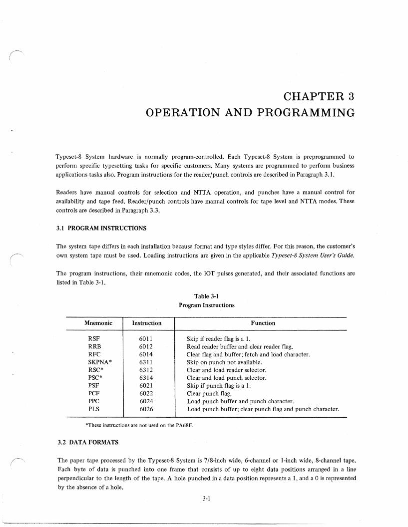
The program instructions, their mnemonic codes, the lOT pulses generated, and their associated functions are
listed in Table 3-1.
Mnemonic
RSF RRB RFC SKPNA* RSC* PSC* PSF PCF PPC PLS
Instruction
6011 6012 6014 6311 6312 6314 6021 6022 6024 6026
Table 3-1
Program Instructions
Skip if reader flag is a 1.
Function
Read reader buffer and clear reader flag. Clear flag and buffer; fetch and load character. Skip on punch not available. Clear and load reader selector. Clear and load punch selector. Skip if punch flag is a 1. Clear punch flag. Load punch buffer and punch character. Load punch buffer; clear punch flag and punch character.
*These instructions are not used on the PA68F.
3.2 DATA FORMATS
The paper tape processed by the Typeset-8 System is 7/8-inch wide, 6-channel or I-inch wide, 8-channel tape.
Each byte of data is punched into one frame that consists of up to eight data positions arranged in a line
perpendicular to the length of the tape. A hole punched in a data position represents ai, and a 0 is represented
by the absence of a hole.
3-1
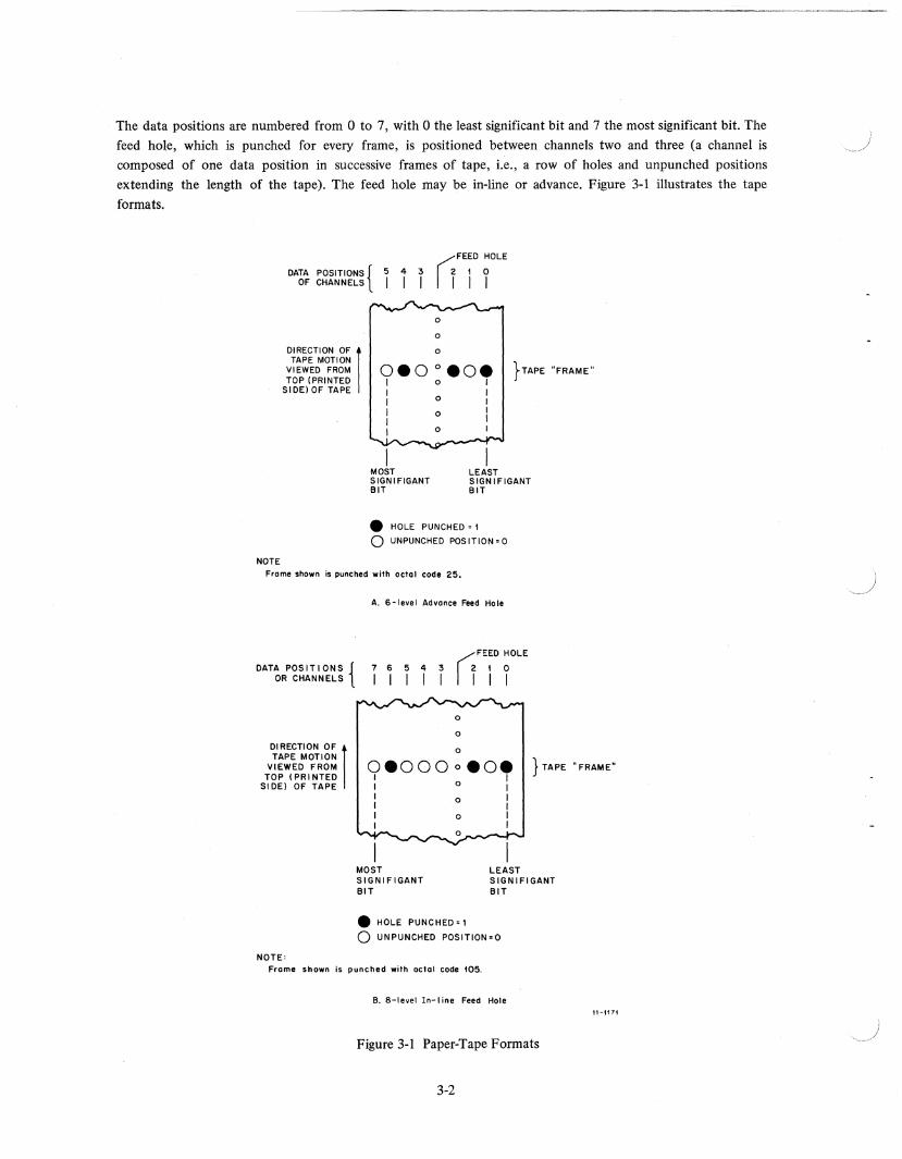
The data positions are numbered from 0 to 7, with 0 the least significant bit and 7 the most significant bit. The
feed hole, which is punched for every frame, is positioned between channels two and three (a channel is composed of one data position in successive frames of tape, i.e., a row of holes and unpunched positions
extending the length of the tape). The feed hole may be in-line or advance. Figure 3-1 illustrates the tape
formats.
DATA POSITIONS { 5 4 3 OF CHANNELS I I I
(jFEED HOLE
2 I 0
I I I
o o o DIRECTION OF I
TAPE MOTION VIEWED FROM TOP (PRINTED
SIDE) OF TAPE
}TAPE "FRAME" 0.0 0 .0. I 0 I
NOTE
I I I 0 I I 0 I I I I 0
I MOST SIGN I FIGANT BIT
LEAST SIGNIFIGANT BIT
• HOLE PUNCHED = I
o UNPUNCHED POSITION=O
Frome shown is punched with octol code 25.
DATA POSITIONS { OR CHANNELS
A. 6-level Advance Feed Hole
(jFEED HOLE
76543 210
I I I I I I I I
o
o
o DIRECTION OF 1 TAPE MOTION
VIEWED FROM TOP (PRI NTED
SI DE) OF TAPE
0.000 0 • O. } TAPE "FRAME" I 0 I
NOTE:
I I I ° I I I I ° I I I
-....... ........ .,-__. 0J"W __ ""'"'
MOST SIGNIFIGANT BIT
• HOLE PUNCHED=1
LEAST SIGNIFIGANT BIT
o UN PUNCHED POSITlON=O
Frome shown is punched with octal code 105.
B. 8-level In-line Feed Hole
Figure 3-1 Paper-Tape Formats
3-2
11-t17t
NOTE For 6-channel tape, bits 06 and 07 are disabled by a switch on the back of the PR68E.
3.3 CONTROLS AND INDICATORS
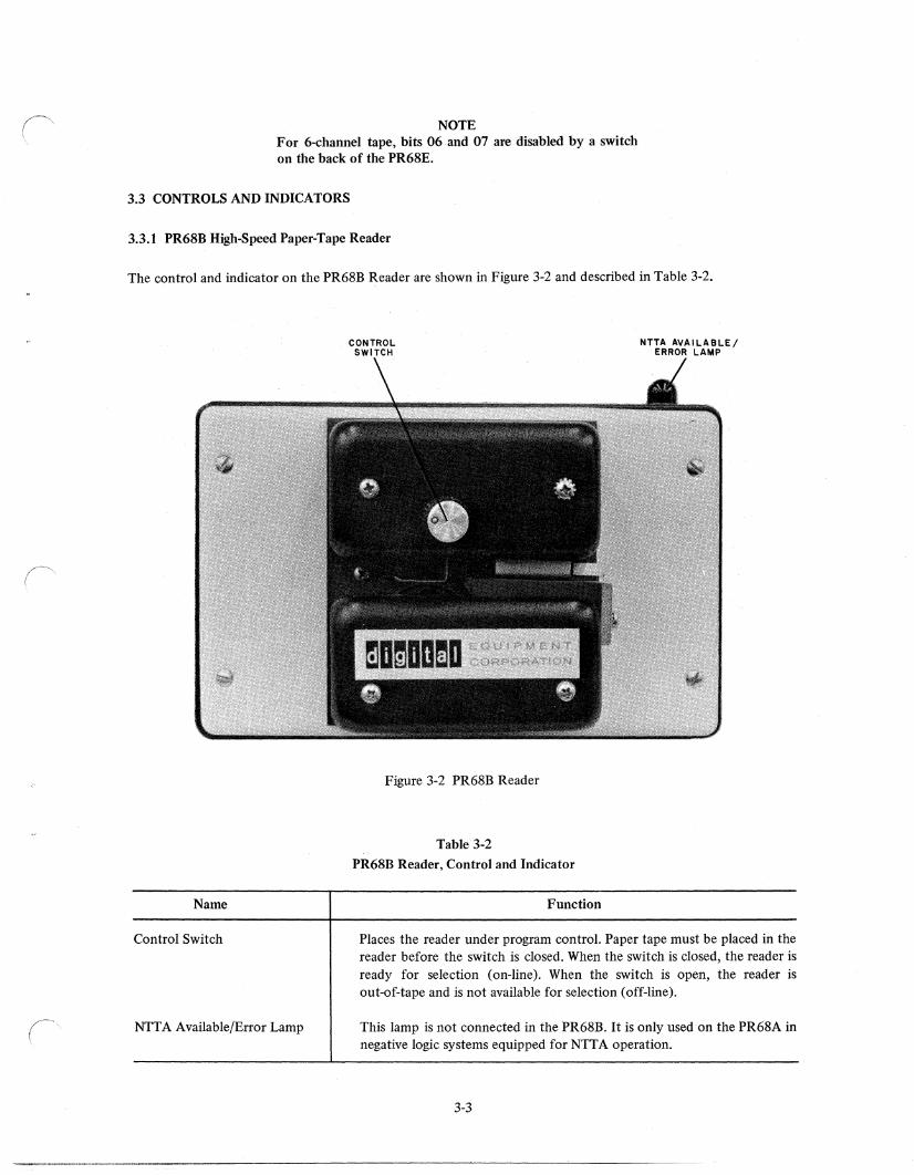
3.3.1 PR68B High-Speed Paper-Tape Reader
The control and indicator on the PR68B Reader are shown in Figure 3-2 and described in Table 3-2.
Name
Control Switch
NTT A Available/Error Lamp
CONTROL SWITCH
Figure 3-2 PR68B Reader
Table 3-2
PR68B Reader, Control and Indicator
Function
NTTA AVAILABLE/ ERROR LAMP
Places the reader under program control. Paper tape must be placed in the reader before the switch is closed. When the switch is closed, the reader is ready for selection (on-line). When the switch is open, the reader is out-of-tape and is not available for selection (off-line).
This lamp is not connected in the PR68B. It is only used on the PR68A in negative logic systems equipped for NTTA operation.
3-3
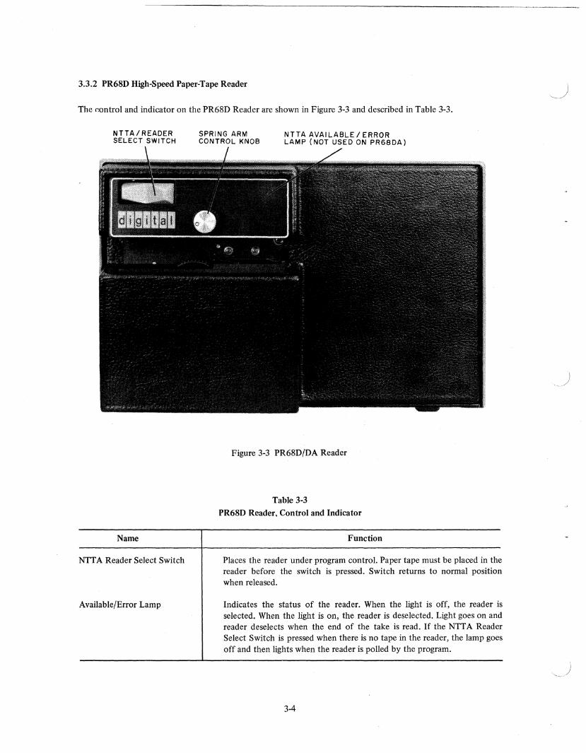
3.3.2 PR68D High-Speed Paper-Tape Reader
The r.ontrol and indicator on the PR68D Reader are shown in Figure 3-3 and described in Table 3-3.
NTTA/READER SELECT SWITCH
Name
NTT A Reader Select Switch
Available/Error Lamp
SPRING ARM CONTROL KNOB
NTTA AVAILABLE/ERROR LAMP (NOT USED ON PR6BDA)
Figure 3-3 PR68D/DA Reader
Table 3-3
PR68D Reader, Control and Indicator
Function
Places the reader under program control. Paper tape must be placed in the reader before the switch is pressed. Switch returns to normal position when released.
Indicates the status of the reader. When the light is off, the reader is selected. When the light is on, the reader is deselected. Light goes on and reader deselects when the end of the take is read. If the NTT A Reader Select Switch is pressed when there is no tape in the reader, the lamp goes off and then lights when the reader is polled by the program.
3-4
r I
3.3.3 PR68DA High-Speed Paper-Tape Reader
The control and indicator on the PR68DA Reader are shown in Figure 3-3 and described in Table 3-4.
Name
Reader Select Switch
NITA Available/Error Lamp
Table 3-4
PR68DA Reader, Control and Indicator
Function
Places the reader under program control. When the switch is depressed to the left, the reader is selected (on-line). When the switch is depressed to the right, the reader is deselected (off-line). To restart the reader after it has been deselected, by pressing the switch to the right, the typesetting program must be restarted.
This lamp is not connected in the PR68DA. Refer to Table 3-3.
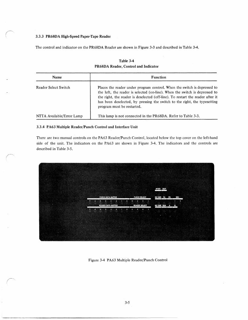
3.3.4 PA63 Multiple Reader/Punch Control and Interface Unit
There are two manual controls on the PA63 Reader/Punch Control, located below the top cover on the left-hand
side of the unit. The indicators on the P A63 are shown in Figure 3-4. The indicators and the controls are
described in Table 3-5.
Figure 3-4 PA63 Multiple Reader/Punch Control
3-5
Name
6/8 LEVEL SWITCH
PUNCH DATA BUFFER
PUNCH SELECT
NO TAPE (punch)
PA (punch active)
PD (punch done)
1 SEC
5 SEC
READER DATA BUFFER
READER SELECT
NO TAPE (reader)
RUN
AlB
INTER
SKIP
NTTAON/OFF
Table 3-5
PA63 Reader/Punch Control, Controls and Indicators
Function
Places the control in the 6- or 8-level tape reading mode. This switch must be set to the position that corresponds to setting of the tape level slide on the reader and the level of the tape being read.
Displays the contents of the punch buffer register. Corresponding lamp is dimly lit when a bit is set.
Displays the octal number of the last punch selected.
Lights when currently selected punch is out-of-tape, i.e., tape supply is below the setting of the tape low switch on the punch.
Displays the state of the punch control. Lamp is lit when the punch is active (on) and off when the punch is done (off).
Displays the state of the punch control. Lamp is lit when the punch is done (off) and off when the punch is active (on).
Displays I-second speed delay. Lamp is lit until delay times out, and punch is up to speed and off when the punch starts perforating tape.
Displays 5-second delay. Lamp is lit until punch J:lll)tor starts and off when the punch starts to run.
Displays the contents of the reader buffer register. Corresponding lamp is lit when a bit is set.
Displays the octal number of the last reader selected.
Lights when there is no tape in the reader or it is stopped. Lamp is dimly lit when it is running with the tape in it.
Displays the state of the reader control. Lamp is off when the reader is not running and lit when the reader is running.
Display the state of the A and B flip-flops in the reader control. Corresponding lamp is lit when the reader is not running and dims when the reader is running.
Displays the state of the interrupt bit. Lamp is lit dvring an interrupt request.
Displays the state of the skip bit. Lamp :c; lit during a skip.
Places the control in the NITA mode. This switch must be set to ON during normal operation. It may be set to OFF when running the TSCE program, making maintenance checks, or using PR68DA Readers.
3-6
)
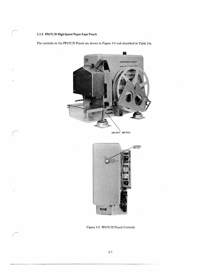
3.3.5 PP67C/D High-Speed Paper-Tape Punch
The controls on the PP67C/D Punch are shown in Figure 3-5 and described in Table 3-6.
ON/OFF SWITCH
Figure 3-5 PP67C!D Punch Controls
3-7
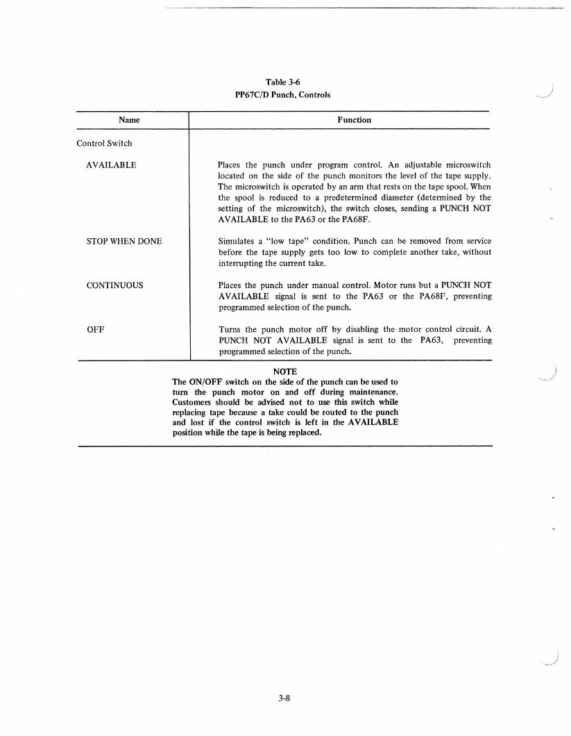
Name
Control Switch
AVAILABLE
STOP WHEN DONE
CONTINUOUS
OFF
Table 3-6
PP67C/D Punch, Controls
Function
Places the punch under program control. An adjustable microswitch located on the side of the punch monitors the level of the tape supply. The microswitch is operated by an arm that rests on the tape spool. When the spool is reduced to a predetermined diameter (determined by the setting of the microswitch), the switch closes, sending a PUNCH NOT AVAILABLE to the PA63 or the PA68F.
Simulates a "low tape" condition. Punch can be removed from service before the tape supply gets too low to complete another take, without interrupting the current take.
Places the punch under manual control. Motor runs but a PUNCH NOT A V AILABLE signal is sent to the PA63 or the PA68F, preventing programmed selection of the punch.
Turns the punch motor off by disabling the motor control circuit. A PUNCH NOT AVAILABLE signal is sent to the PA63, preventing programmed selection of the punch.
NOTE The ON/OFF switch on the side of the punch can be used to turn the punch motor on and off during maintenance. Customers should be advised not to use this switch while replacing tape because a take could be routed to the punch and lost if the control switch is left in the AVAILABLE position while the tape is being replaced.
3-8
CHAPTER 4 THEORY OF OPERATION
This section contains detailed information on the theory of operation of the positive logic hardware used in the
Typeset-8 Systems. The information presented in this section is directed toward DEC-trained maintenance
personnel and is intended to ensure a complete understanding of all operating characteristics of the system. It
also permits on-site maintenance of typesetting systems by maintenance personnel, who-are qualified to service
the processors, but have not been formally trained in the operation, theory, and maintenance of Typeset-8
Systems.
The engineering drawings in Volume II of this manual represent the latest revisions available at the time of
printing. However, Typeset-8 Systems are continually being changed and upgraded to satisfy specific customer
requirements. Therefore, these drawings and the detailed theory description contained in this manual should be
used only as a guide to understanding system operation. For troubleshooting and repairing a specific system
installation, use the on-site engineering drawings, and call Maynard often.
4.1 PA63 MULTIPLE READER/PUNCH CONTROL AND INTERFACE UNIT
The PA63 Multiple Reader/Punch Control and Interface Unit is a controller and interface for the positive logic
processors in the PDP-8 series. Up to 16 readers and punches can be interfaced to the unit. One reader and one
punch can be selected at a time.
The reader control turns the stepping motor in the selected reader on and off as directed by the processor and
the program. It also buffers the data after directing the selected reader to fetch a character.
The punch control turns the ac motor in the selected punch on and off and energizes the punch solenoids as
directed by the processor and the program. ][t also buffers the data after it is transferred from the processor.
The logic and circuit diagrams for the PA63 are listed in the Master Drawing List:
Drawing No. A-ML-PA63-0
Title 16-Channel Reader/Punch Multiplexer
The PA63 is housed in a standard H925 module drawer that has 36 H803 mounting blocks. The module drawer
is mounted using chassis tracks. The PA63 contains 52 integrated circuit modules when two readers and two
punches are connected. Additional M060 Solenoid Drivers are added as required when more readers are
connected to the system.
4-1
4.1.1 Power Up
An INITIALIZE pulse is generated in the processor when the power is turned on and also when the START key (CLEAR/CO NT) is pressed. In the reader control, this pulse clears:
a. reader selection register flip-flops (RSBO, RSB 1, RSB 2 and RSB4) (P A63-0-04) b. RUN flip-flop (PA63-0-09) c. FLAG flip-flop
In the punch control, this pulse clears:
a. punch selection register flip-flops (PSBO, PSBl, PSB2 and PSB4) (PA63-0-03) b. PUNCH ACTIVE flip-flop (PA63-0-08) c. FLAG flip-flop
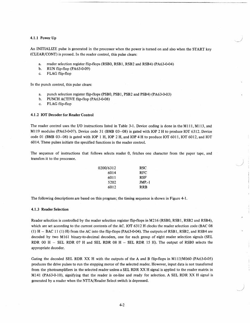
4.1.2 lOT Decoder for Reader Control
The reader control uses the I/O instructions listed in Table 3-1. Device coding is done in the MIll, Ml13, and
M 119 modules (PA63-0-07). Device code 31 (BMB 03-08) is gated with lOP 2 H to produce lOT 6312. Device
code 01 (BMB 03-08) is gated with lOP 1 H, lOP 2 H, and lOP 4 H to produce lOT 6011, lOT 6012, and lOT
6014. These pulses initiate the specified functions in the reader control.
The sequence of instructions that follows selects reader 0, fetches one character from the paper tape, and transfers it to the processor.
0200/6312 6014 6011 5202 6012
RSC RFC RSF JMP.-I RRB
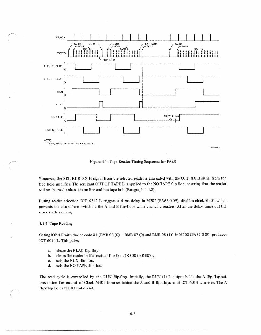
The following descriptions are based on this program; the timing sequence is shown in Figure 4-1.
4.1.3 Reader Selection
Reader selection is controlled by the reader selection register flip-flops in M216 (RSBO, RSB 1, RSB2 and RSB4),
which are set according to the current contents of the AC. lOT 6312 H clocks the reader selection code (BAC 08
(1) H - BAC 11 (1) H) from the AC into the flip-flops (PA63-0-04). The outputs of RSB 1, RSB2, and RSB4 are
decoded by two M 161 binary-to-decimal decoders, one for each group of eight reader selection signals (SEL
RDR 00 H - SEL RDR 07 Hand SEL RDR 08 H - SEL RDR 15 H). The output of RSBO selects the
appropriate decoder.
Gating the decoded SEL RDR XX H with the outputs of the A and B flip-flops in M113/M060 (PA63-0-05)
produces the drive pulses to run the stepping motor of the selected reader. However, input data is not transferred
from the photoamplifiers in the selected reader unless a SEL RDR XX H signal is applied to the reader matrix in
M141 (PA63-0-1O), signifying that the reader is on-line and ready for selection. A SEL RDR XX H signal is
generated by a reader when the NTT A/Reader Select switch is depressed.
4-2
CLOCK
IOT'S
;;SKP 6011
r 6012 6011'S '1'111111,1"11,1 '11"""",,1111
~~~~~~~~~~~~~~~I~ _______ ~~~~~~~~~UL
1
A FLI P- FLOP ~ IL. __ ~ i ------ulL. __ ~ I r:--------
L.... __ -' 1 B FLI P-FLOP
o 1
~ LL--------_~ RUN ~ J I
FLAG 0 ______ --'IL, ______ -'rL ______________ ..J
NO TAPE: ~
H---..., L....---l1----------ROR STROBE L
NOTE: Timing diagram is n01 drawn to scole.
08-0783
Figure 4-1 Tape Reader Timing Sequence for PA63
Moreover, the SEL RDR XX H signal from the selected reader is also gated with the O. T. XX H signal from the
feed hole amplifier. The resultant OUT OF TAPE L is applied to the NO TAPE flip-flop, ensuring that the reader
will not be read unless it is on-line and has tape in it (Paragraph 4.4.3).
During reader selection lOT 6312 L triggers a 4 ms delay in M302 (PA63-0-09), disables clock M 40 I which
prevents the clock from switching the A and B flip-flops while changing readers. After the delay times out the
clock starts running.
4.1.4 Tape Reading
Gating lOP 4 H with device code 01 [BMB 03 (0) - BMB 07 (0) and BMB 08 (1)] in M 1 03 (P A63-0-09) produces
lOT 6014 L. This pulse:
a. clears the FLAG flip-flop; b. clears the reader buffer register flip-flops (RBOO to RB07); c. sets the RUN flip-flop; d. sets the NO TAPE flip-flop.
The read cycle is controlled by the RUN flip-flop. Initially, the RUN (1) L output holds the A flip-flop set,
preventing the output of Clock M40l from switching the A and B flip-flops until lOT 6014 L arrives. The A
flip-flop holds the B flip-flop set.
4-3
After the RUN flip-flop is set, the switching sequence is:
STATIC
DYNAMIC
A
o o
B
1 o o
Four pulses are generated during each cycle. Switching the A flip-flop to a 0 produces the first pulse to the gates
and drivers in M l13/M060. This pulse moves the frame in the tape over the photocells in the read head.
Switching the B flip-flop to a 0 produces the second pulse.
Gating this pulse ~B (0) HJ with RUN (1) H in MIlS produces a RDR STROBE pulse. READER STROBE H
clocks the input data from data selection matrix M 141 into the reader buffer register flip-flops, loading the
buffer while the holes are still over the photocells. A high data input (no hole) sets the corresponding flip-flop.
Thus, the current character is fetched from the tape and loaded into the buffer.
Switching the A flip-flop to a 1 again produces the third pulse to the gates and drivers in M l13/M060. Switching
the B flip-flop to a 1 produces the fourth pulse, B (0) L. This pulse disqualifies the gate in MIlS that produces
RDR STROBE. The resulting positive transition (-RDR STROBE L) clears the RUN flip-flop because the data
input is grounded and the direct clear input is connected to +3 Vdc. The RUN (1) L output holds the A flip-flop
set.
RUN (0) H attempts to set the FLAG flip-flop. As the feed hole in the tape passes over the photocell, the
resulting positive transition (-OUT OF TAPE L) clears the NO TAPE flip-flop, allowing RUN (0) H to set the
flag. When the reader runs out of tape, the positive transition does not occur and the NO TAPE flip-flop remains
set because the data input is grounded and the direct clear input is connected to +3 Vdc. Consequently, the
FLAG flip-flop can only be set when there is tape in the reader and the reader is on-line.
This condition is tested by the 6011 instruction. During the read cycle, the processor generates a series ofIOP 1
H pulses. Gating these pulses with device code 01 in M103 produces ][OT 6011 L pulses. These pulses are in tum
gated with FLAG (1) L in M624 to produce a SKIP BUS L pulse if the flag is set. The lOT 6011 L pulse that
causes the SKIP BUS L pulse may occur coincident with the setting of the FLAG flip-flop or it may occur after
the FLAG flip-flop is set. When the SKIP BUS L pulse occurs, the processor skips the 5202 instruction and
executes the 6012 instruction.
FLAG (1) L also produces an unconditional interrupt request (INT RQST BUS L). This signal may be used
instead of the 6011 instruction to initiate the transfer of data from the buffer to the processor.
Gating lOP 2 H with device code 01 produces an lOT 6012 L pulse. This pulse:
1. clears the FLAG flip-flop, and 2. gates the contents of the reader buffer to the processor.
Thus, the current character is transferred from the buffer to the processor. A low input from a cleared flip-flop
causes the corresponding gate to produce a low output. As a result, the holes in the input tape are translated to
Is.
4-4
I }
(" \ 4.1.5 lOT Decoder for Punch Control
The punch control uses the I/O instructions listed in Table 3-1. Device decoding takes place in the MIll, MI13,
M119, and M710 modules. Device code 31 (BMB 03-08) is gated with lOP 1 H and lOP 4 H to produce lOT
6311 and lOT 6314 (p A63-0-07). Device code 02 (BMB 03-08) is gated with BIOP 1 H, BIOP 2 H, and BIOP 4 H (PA63-0-08) to produce lOT 6021, lOT 6022, and lOT 6024. These pulses initiate the specified functions in
the punch control.
The sequence of instructions that follows selects punch 0, checks that the punch is available, transfers one byte
of data from the processor, and punches it in the paper tape. If the punch is not available a halt occurs.
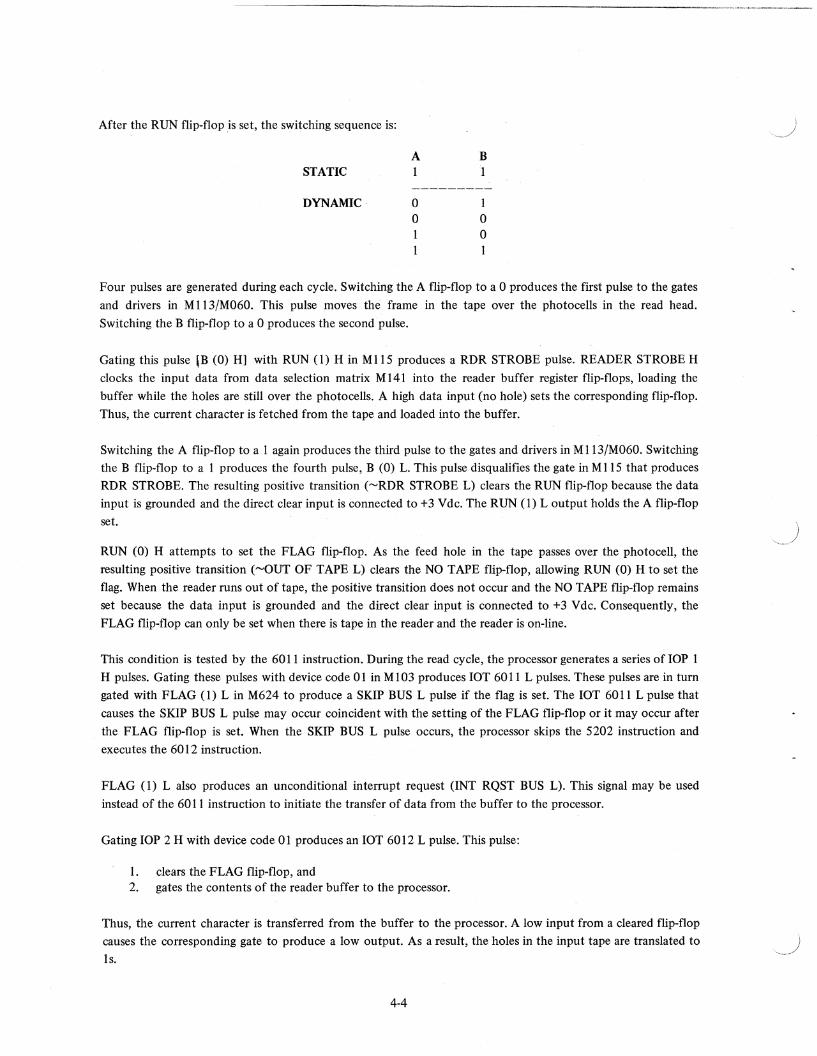
0200/6314 PSC 6314 SKPNA 7410 SKP 7402 HLT 6022 PCF 6024 PPC 6021 PSF 5202 JMP.-l
The following logic descriptions are based on this program. The timing sequence is shown in Figure 4-2.
SYNC PUNCH
IOT'S
1 PUNCH ACTIVE
6314
O-~-----------!
1--------------, FLAG 1 o .
I I I I I
11111111111 11111111111
H----------------------~ I MOTOR START : 5$ J L !--------+'---~------:~-----I I
I I
DL PUNCH DONE: -------------+------I14.5msec I~----------------
INHIBIT H J=hec::j Flsec==! L .L-________ -J ~ ____________________ ~
M302 M710
NOTE: Timing diagram is nat drawn to scale.
08-0785
Figure 4-2 Tape Punch Timing Sequence for PA63
4-5
4.1.6 Punch Selection
Punch selection is controlled by the punch selection buffer register flip-flops(PSBO - PSB4) in M216, which are
set according to the current contents of the AC. lOT 6314 H clocks the punch selection code (BAC 08 (1) H -BAC II (I) H) from the AC into the flip-flops (P A63-0-03).
The outputs of flip-flops PSB I - PSB4 are decoded by two M 161 binary-to-decimal decoders, one for each group of eight punch selection signals (SEL 00 H - SEL 07 Hand SEL 08 H - SEL 15 H). The output of flip-flop PSBO selects the appropriate decoder.
Gating the decoded SEL XX L with MOTOR START L in M623/624 produces MOTOR START XX L for the selected punch. MOTOR START XX L turns on the punch motor and the SCR that supplies +30 Vdc for the
solenoids of the selected punch by grounding the motor control circuit punch control G915 (paragraph 4.1. 7).
However, MOTOR START L is not produced until the 6024 instruction is executed.
lOT 6314 L triggers a I-second delay in M302 (p A63-0-08) that interrupts the INHIBIT L input to the SYNC
flip-flop. Thus, SYNC PUNCH pulses from the selected punch cannot trigger the 4.5 ms pulse shaper while switching between punches to allow the selected punch to get up to speed.
The availability of the selected punch is checked by gating SEL XX H with NOT AVAIL XX H in M 141. If the
control switch on the punch is not in the AVAILABLE position or the tape supply is low (below the setting of the low tape limit switch), NOT AVAIL XX Hand SEL XX H produce a low input to M623. This condition is
tested by the 6311 instruction. Gating lOP I with device code 31 in M 113/M III produces lOT 6311 L. Gating this lOT in M623 with the low input from Ml41 produces SKIP BUS L. This pulse causes the processor to skip
the next instruction and halt.
When the control switch on the selected punch is in the AVAILABLE position and the punch has sufficient tape,
the SKIP BUS L pulse is not produced and the processor executes the 6022 instruction.
4.1.7 . Tape Punching
Gating BIOP 2 with device code 02 [BMB 03 (0) - BMB 06 (0), BMB 07 (1) and BMB 08 (0)] in M710
(PA63-0-08) produces an lOT 6022 L pulse. This pulse clears:
a. the PUNCH ACTIVE flip·flop; b. the PUNCH FLAG flip-flop.
The next instruction (6024) starts the punching cycle. The device code from Ml19 produces an AC STROBE H pulse, which gates the data [BAC 4 (1) - BAC 11 (1)] from the processor through MIOl/Mlll to the punch
buffer.
Gating device code 02 with BIOP 4 in M710 produces an lOT 6024 pulse. lOT 6024 (A) H clocks data into
punch buffer register flip-flops PB-O thro\lgh PB-3. lOT 6024 (B) H clocks data into punch buffer register flip-flops PB·4 through PB-7. A high data input sets the corresponding flip-flop. lOT 6024 L sets the PUNCH ACTIVE flip-flop.
4-6
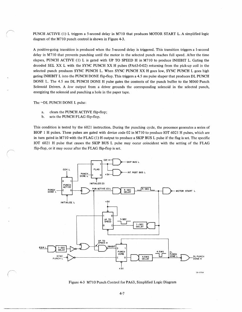
PUNCH ACTIVE (1) L triggers a 5-second delay in M710 that produces MOTOR START L. A simplified logic
diagram of the M710 punch control is shown in Figure 4-3.
A positive-going transition is produced when the 5-second delay is triggered. This transition triggers a I-second
delay in M710 that prevents punching until the motor in the selected punch reaches full speed. After the time
elapses, PUNCH ACTIVE (1) L is gated with UP TO SPEED H in M71 0 to produce INHIBIT L. Gating the
decoded SEL XX L with the SYNC PUNCH XX H pulses (PA63-0-02) returning from the pick-up coil in the
selected punch produces SYNC PUNCH L. When SYNC PUNCH XX H goes low, SYNC PUNCH L goes high
gating INHIBIT L into the PUNCH DONE flip-flop. This triggers a 4.5 ms pulse shaper that produces DL PUNCH
DONE L. The 4.5 ms DL PUNCH DONE H pulse gates the contents of the punch buffer to the M060 Punch
Solenoid Drivers. A low output from a driver grounds the corresponding solenoid in the selected punch,
energizing the solenoid and punching a hole in the paper tape.
The ~DL PUNCH DONE L pulse:
a. clears the PUNCH ACTIVE flip-flop; b. sets the PUNCH FLAG flip-flop.
This condition is tested by the 6021 instruction. During the punching cycle, the processor generates a series of
BIOP 1 H pulses. These pulses are gated with device code 02 in M710 to produce lOT 6021 H pulses, which are
in turn gated in M71 0 with the FLAG (1) H output to produce a SKIP BUS L pulse if the flag is set. The specific
lOT 6021 H pulse that causes the SKIP BUS L pulse may occur coincident with the setting of the FLAG
flip-flop, or it may occur after the FLAG flip-flop is set.
024 l
o PUNCH ACTIVE
b~~~Hl C 0
INITIALIZE l
,----10
FLAG £21H
SKIP BUS l 1
INT RQST BUS l o +3V
INITIALIZE (0)
PUN ACTIVE (O)l r--_....I..-----, ~ f---==---==--""'---l
+3V
UP TO SPEED
() C
I-SEC
L-.J
o PUNCH DONE
4.5MS
SYNC PUNCH l '»----------1 C 0 --u-
+3V
MOTOR START l
DL PUNCH DONE L Dl PUNCH
DONE H
08-0784
Figure 4-3 M710 Punch Control for PA63, Simplified Logic Diagram
4-7
When the SKIP BUS L pulse occurs, the processor skips the 5202 instruction. FLAG (1) H also produces an
unconditional intenupt request (INT RQST BUS L). This signal may be used instead of the 6011 instruction to
terminate the punching cycle. If another lOT 6024 L pulse is not generated within 5 seconds, the delay in M7l0
times out, turning the punch motor off and clearing the I-second flip .. flop.
4.2 PA68F SINGLE READER/PUNCH CONTROL AND INTERFACE UNIT
The PA68F is a controller and interface for the positive logic processors in the PDP-8 series. The reader control
turns the stepping motor in the selected reader on and off as directed by the processor and the program. It also
buffers the data after directing the selected reader to fetch a character.
The punch control turns the ac motor in the selected punch on and off and energizes the punch solenoids as
directed by the processor and the program. It also buffers the data after it is transfened from the processor.
The logic and circuit diagrams for the P A68F are listed in the Master Drawing List:
Drawing No. A-ML-P A63-0
Title Reader and Punch Control
The PA68F is housed in a modified H9ll Mounting Panel that has six H803 Mounting blocks instead of eight.
An H7l6 Power Supply is mounted on the H9ll in the slot where the two mounting blocks were removed. The
PA68F contains 17 integrated circuit modules.
4.2.1 Power Up
An INITIALIZE pulse is generated in the processor when power is turned on and also when the START
(CLEAR/CO NT) key is pressed. In the reader control, this pulse:
a. disables clock M40l, preventing a tape feed cycle if the RUN flip-flop is set; b. clears the RUN flip-flop; c. clears the FLAG flip-flop.
In the punch control, this pulse clears:
a. the PUNCH ACTIVE flip-flop; b. the PUNCH FLAG flip-flop.
4.2.2 lOT Decoder for Reader Control
The reader control (PA68F-l) uses the I/O instructions listed in Table 3-1. Device decoding takes place in the
MI03 module. Device code 01 (BMB 03-08) is gated with lOP 1, lOP 2 and lOP 3 to produce lOT 6011, lOT
6012 and lOT 6014. These pulses initiate the specified functions in the reader control.
The sequence of instructions that follows fetches one character from the paper tape and transfers it to the
processor.
0200/6014 6011 5202 6012
4-8
RFC RSF JMP.-l RRB
)
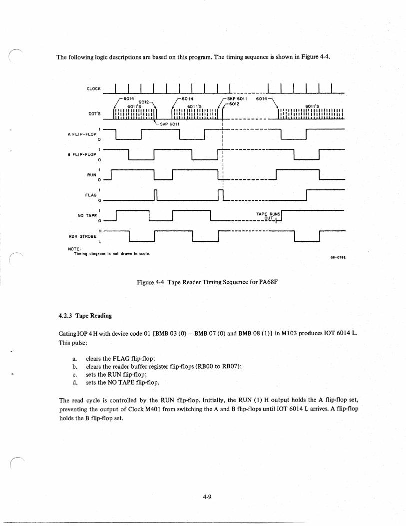
The following logic descriptions are based on this program. The timing sequence is shown in Figure 44.
SKP 6011 60'2
6014,""\
tOT'S
\ 601l'S 111,1' "' 11111111 II 11111" "tlIIIII" 111'"11'"1 __ ~.u~~~~ __ ~~~~~~~~~ _________ ~~~~~~~~
A FLIP-FLOP ~ 1 ... __ --' ! ----~----I I '------~ I r:----..., ...... ---.
\.r-If -~ ,
1---.., B FLIP-FLOP
o I
L---J. LL----------~ I I
, n fL' FLAG o ---..-------' .... -------.-..,.-- . ~ --- .... - ...... - .... ~_......,..._~
NO TAPE: ~ TAPE RUNSI '--__ """ ________ 2~T .. J_I
H----... ROR STROBE
L
NOTE: Timing diagram is not drawn 10 lIto'e.
08-0782
Figure 4-4 Tape Reader Timing Sequence for PA68F
4.2.3 Tape Reading
GatingIOP4Hwithdevice code 01 [BMS 03 (0) - 5MB 07 (0) and SMS 08 (1») in MI03 proc,iuces lOT 6014 L.
This pulse:
a. clears the FLAG flip-flop; b. clears the reader buffer regis~er flip-flops (RSOO to RB07); c. sets the RUN flip·flop; d. sets the NO TAPE flip.flop.
The read cycle is controlled by the RUN flip-flop. Initially, the RUN (1) H output holds the Aflip·flop ~et,
preventing the output of Clock M401 from switching the A and B flip·flops until lOT 6014 L arriveS. A flip-flop
holds the B flip-flop set.
4-9
After the RUN flip-flop is set, the switching sequence is:
STATIC
DYNAMIC
A I
o o
B
o o I
Four pulses are generated during each cycle. Switching the A flip-flop to a 0 produces the first pulse to the gate
and driver in M 113/M060. This pulse moves the frame in the tape over the photocells in the read head.
Switching the B flip-flop to a 0 produces the second pulse. Gating this pulse [B,(O) H) with RUN (1) H in MilS
produces aRDR STROBE pulse. READER STROBE H clocks the input data from the photoamplifiers in the
reader into the buffer register flip-flops, loading the buffer while the holes are still over the photocells. A high
data input (hole) sets the corresponding flip-flop. Thus, the current character is fetched from the tape and
loaded into the buffer.
Switching the A flip-flop to a I produces the third pulse to the gate and driver in MI13/M060. Switching the B
flip-flop to a I produces the fourth pulse, B (0) L. This pulse disqualifies the gate in MilS that produces RDR
STROBE. The resulting positive transition ("'RDR STROBE L) clears the RUN flip-flop because the data input
is grounded. RUN (1) H holds the A flip-flop set. The four pulses generated by the A/B flip-flops are inhibited
. by "'SEL RDR H when the reader is deselected. This keeps the motor in the reader turned off when it is
deselected so that it does not overheat.
RUN (0) H attempts to set the FLAG flip-flop. As the feed hole in the tape passes over the photocell, the
resulting positive transition ("'0UT OF TAPE L) clears the NO TAPE flip-flop, allowing RUN (0) H to set the
flag. When the reader runs out of tape or is deselected, the positive transition does not occur and the NO TAPE
flip-flop remains set. Consequently, the FLAG flip-flop can only be set when there is tape in the reader and the
reader is on-line.
This condition is tested by the 6011 instruction. During the read cycle, the processor generates a series of lOP 1
H pulses. Gating these pulses with device code 01 in MI03 produces lOT 6011 L pulses. These pulses are gated
with FLAG (0) H in M623 to produce a SKIP BUS L pulse if the flag is set. The lOT 6011 L pulse that causes
the SKIP BUS L pulse may occur coincident with the setting of the FLAG flip-flop or it may occur after the
FLAG flip-flop is set. When the SKIP BUS L pulse occurs, the processor skips the S202 instruction and executes
the 6012 instruction.
FLAG (0) H also produces an unconditional interrupt request (lNT RQST BUS L). This signal may be used
instead of the 60 II instruction to initiate the transfer of data from the buffer to the processor.
Gating lOP 2 H with device code 01 produces an lOT 6012 L pulse. This pulse:
1. clears the FLAG flip-flop, 2. gates the contents of the reader buffer to the processor.
4-10
,.~
Thus, the current character is transferred from the buffer to processor. A low input from a set flip-flop causes the corresponding gate to produce a low output. As a result, the holes in the input tape are translated to Is.
4.2.4 lOT Decoder for Punch Control
The punch control (PA68F-2) uses the I/O instructions listed in Table 3-1, Device decoding takes place in the
Ml13, M119, and M710 modules. Device code 02 (BMB 03.....:08) is gated with lOP 1 H, lOP 2 H and lOP 4 H to produce lOT 6021, lOT 6022, and lOT 6024. These pulses initiate the specified functions in the punch control.
The sequence of instructions that follows transfers one byte of data from the processor and punches it in the paper tape.
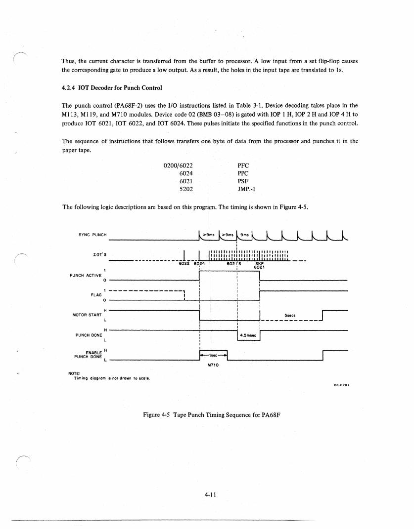
0200/6022 6024 6021 5202
PFC PPC PSF JMP,-l
The following logic descriptions are based on this progr~m. The timing is shown in F~re 4-5.
SYNC PUNCH
rOT'S ____ - _____________ 1 ... _ .~-+lL..U.U-j.~,&.I,JI,U-J,.U.~~I,..I.I.,U,I.uJ".. 6022 6624 ' ,
PUNCH ACTIVE 1 j I o ------------------------~I , I 1
! ,I , ------- .... -----""--, FLAG I
o I 1 'I' I I 1
MOTOR START: ---------------.il!-____ -+I __ ~L-- __ ~:~----J 1 I'
H----~-_____________________ ~I __ ~ ____ ~I '
PUNCH DONE L t 14 .5msee I 1 1
ENABLE H I- ::::::J PUNCH DONE L ________________ ~, 1s.e~\_---__ -_-______ ___'
M710
NOTE: Timinll diallram is nat drawn to scale.
Figure 4-5 Tape Punch Timing Sequence for PA68F
4·11
08-078'
4.2.5 Tape Punching
Gating lOP 2 with device code 02 [BMB 03 (0) - BMB 06 (0), BMB 07 (1) and BMB 08 (0)] in M7l0 produces
an lOT 6022 L pulse. This pulse clears:
a. the PUNCH ACTIVE flip-flop; b. the PUNCH FLAG flip-flop.
The next instruction (6024) starts the punching cycle. The device code from Ml19 produces an AC STROBE H
pulse. This pulse gates the data [BAC 4 (1) - BAC 11 (1)] from the processor through MlOl/M113 to the
punch buffer.
Gating device code 02 with lOP 4 in M710 produces an lOT 6024 pulse. lOT 6024 H clocks the data into the
punch buffer register flip-flops. A high data input sets the corresponding flip-flop, loading the associated buffer.
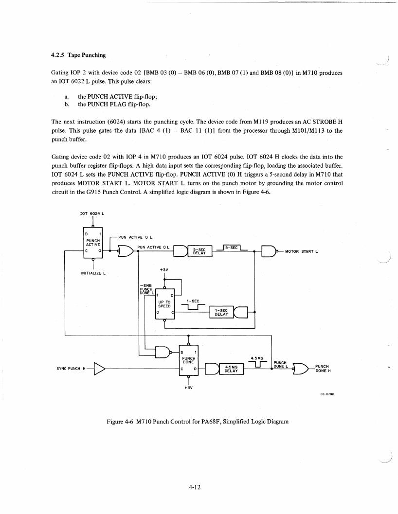
lOT 6024 L sets the PUNCH ACTIVE flip-flop. PUNCH ACTIVE (0) H triggers a 5-second delay in M71 0 that
produces MOTOR START L. MOTOR START L turns on the punch motor by grounding the motor control
circuit in the G915 Punch Control. A simplified logic diagram is shown in Figure 4-6.
lOT 6024 L
D
PUNCH ACTIVE
,-----1C 0
INITIALIZE L
PUN ACTIVE 0 L
+3V
-ENB PUNCH ,...-""'--, DONE L 1
D
PUNCH DONE
SYNC PUNCH H >-------------------,C 0
+3V
4.5MS
L.r
MOTOR START L
PUNCH DONE L PUNCH
DONE H
08-0780
Figure 4-6 M710 Punch Control for PA68F, Simplified Logic Diagram
4-12
A positive-going transition is produced when the 5-second delay is triggered. This transition triggers a I-second
delay in M7IO that prevents punching until the motor reaches full speed. After the time elapses, -ENB PUNCH
DONE L allows the incoming SYNC PUNCH H pulses returning from the punch pick-up coil to be gated with
PUNCH ACTIVE (0) H in M71O, triggering a 4.5 ms pulse shaper that produces PUNCH DONE H. The 4.5 ms
PUNCH DONE H pulse gates the contents of the punch buffer to the M060 Punch Solenoid Drivers; a low
output from a driver grounds the corresponding solenoid, energizing it, and punching a hole in the paper tape.
When the 4.5 ms delay times out:
a. the PUNCH ACTIVE flip-flop is cleared; b. the PUNCH FLAG flip-flop is set.
This condition is tested by the 6021 instruction. During the punching cycle, the processor generates a series of
lOP I pulses. These pulses are gated with device code 02 in M710 to produce lOT 6021 H pulses. These pulses
are gated with the FLAG (1) H to produce a BUS SKIP L pulse if the flag is set. The lOT 6021 H pulse that
causes the BUS SKIP L pulse may occur coincident with the setting of the PUNCH FLAG flip-flop or it may
occur after the PUNCH FLAG flip-flop is set.
When the BUS SKIP L pulse occurs, the processor skips the 5202 instruction. FLAG (1) H also produces an
unconditional interrupt request (INTER BUS L). This signal may be used instead of the 6011 instruction to
terminate the punching cycle. If another lOT 6024 L pulse is not generated within 5 seconds, the delay in M71 0
times out, turning the punch motor off and clearing the I-second flip-flop.
4.3 PR68B HIGH-SPEED PAPER-TAPE READER
The PR68B is a positive logic version of the PR68A. It can be set up to read either 6-level advance feed hole or
8-level in-line feed hole tape. Reading rate is 110 cps. Operating voltages and signals are compatible with both
the PR68F Single Reader/Punch Control and Interface Unit and the PA63 Multiple Reader/Punch Control Unit.
The circuit diagrams for the PR68B are listed in the Master Drawing List:
Drawing No. A-ML-PR68-B
Title Reader (Typesetting System)
With the exception of the voltages and signal polarities (shown on the block wiring diagram), the PR68B is
identical to the PR68A. A single G908 Photoamplifier Module is used to monitor the outputs of the photodiodes and produce +3.6 Vdc when a hole is sensed and 0 Vdc when no hole is sensed.
The bias level of all nine photoamplifiers is determined by the setting of the threshold sensitivity potentiometer, R52. Drawing C-CS-G908-O-1 shows the circuit configuration of the amplifiers.
4.4 PR68D HIGH-SPEED PAPER-TAPE READER
The PR68D is a redesigned and improved reader equipped with a non torn tape (NTT A) processing feature. This
feature is implemented by adding a G930 module to the PR68DA and making some minor modifications.
Operating voltages and signals are compatible with the PA63 Multiple Reader/Punch Control and Interface Unit.
4-13
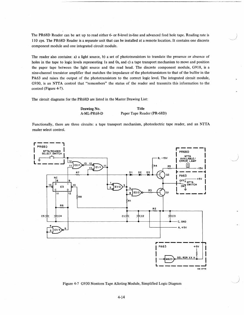
The PR68D Reader can be set up to read either 6- or 8-level in-line and advanced feed hole tape. Reading rate is
110 cps. The PR68D Reader is a separate unit that can be installed at a remote location. It contains one discrete
component module and one integrated circuit module.
The reader also contains: a) a light source, b) a set of phototransistors to translate the presence or absence of
holes in the tape to logic levels representing Is and Os, and c) a tape transport mechanism to move and position the paper tape between the light source and the read head. The discrete component module, G918, is a nine-channel transistor amplifier that matches the impedance of the phototransistors to that of the buffer in the PA63 and raises the output of the phototransistors to the correct logic level. The integrated circuit module, G930, is an NITA control that "remembers" the status of the reader and transmits this information to the control (Figure 4-7).
The circuit diagrams for the PR68D are listed in the Master Drawing List:
Title Drawing No. A-ML-PR68-D Paper Tape Reader (PR-68D)
Functionally, there are three circuits: a tape transport mechanism, photoelectric tape reader, and an NTTA
reader select control.
r----' PR68D
I NTTA/READER I I ~~~W_I_TC_H~~ ________________ ~
L':' ___ ..J B. -15V
R8
Rl
R6 R2
C5 C4 Cl C2 C3
L---4-----+---------------------------~--~~--_+----+_---*---C.GND
L-__ -I-_______ A. +5V
,.-------PA63 +5V
SEL RDR xx H
L· _______ --J 08-0779
Figure 4-7 G930 Nontorn Tape Alloting Module, Simplified Logic Diagram
4-14
(\ \
4.4.1 Tape Transport Mechanism
A tape-drive sprocket, rotated by a 4-pole, dc-operated synchronous motor, performs the tape-feeding function.
Pins on this wheel engage feed holes in the tape to transport the tape past the read station. High-current drive
pulses, generated by solenoid drivers in the PA63 produce the required torque in the motor.
Two switch-tail-connected flip-flops (A and B) in the PA63 provide the pair-sequential triggering outputs that
control the solenoid drivers. Four feed cycles are required to move the tape a distance equal to one character
position. Switching the activation of the solenoid pairs at 2.3 ms intervals produces a tape-feeding rate of 110 cps.
4.4.2 Photoelectric Tape Reader
The tape reading function is performed by the photoelectric tape reader. This reader consists of a light source, a photoelectric read head and associated amplifier circuits for the photocell outputs. The amplifier circuits are in
the G918 module.
The read head, located below the tape, contains nine light sensitive semiconductors, physically arranged to sense perforations in the eight data tracks or channels of the tape and in the feed tape hole track. The light source is
directly above the photocells. The outputs of the photocells change between the light and no-light conditions. Light passing through a hole in the tape activates the associated photocell.
The nine photoamplifier circuits in the G918 module continuously monitor the outputs of the photocells for
transmission to the PA63. The bias level of all nine photoamplifiers is determined by the setting of threshold potentiometer, R37. The amplifiers generate a +3.6 Vdc output level when a hole is sensed and a 0 Vdc level
when no hole is sensed. The PA63 controls the transmission of the data read from the tape and the position of the tape, which is determined by the state of the A and B flip-flops. The feed hole amplifier output is monitored
to detect the out-of-tape condition.
4.4.3 NTTA Reader Selection
Reader selection is controlled as described in Paragraph 4.1.3. The G930 module assumes control of reader
selection when no input tape is ready for processing.
Since flip-flop E3 is cleared initially, the reader is not available for selection when the program is started. Consequently, the output of QI holds SEL RDR XX H at ground as the PA63 sequentially steps through each reader in the normal manner, searching for one that is available for selection. This output holds RDR SEL XX H at ground because Q I in the G930 module and the corresponding M623 driver in the P A63 are both connected to the +5 Vdc source through the same resistor. Thus, SEL RDR XX H can not go up to that level unless QI is timed off.
When the switch on the reader is closed, the input to EI/2 and E2/2 is grounded, cutting off transistors QI and Q2. Consequently, the lamp on the reader goes off because it is not grounded. More importantly, the output of
QI is allowed to follow SEL RDR XX H. Thus, the reader is ready for program selection, but it is not selected because -SEL RDR XX H from the PA63 holds the logic level at ground. The switch closure is "remembered"
by E 1/ 1 and E2/ I, which hold Q 1 and Q2 in cut-off until flip-flop E3 changes state.
4-15
When the PA63 produces SEL RDR XX H for the available reader, the reader is selected and input tape
processing begins. However, this does not effect the flip-flop because the change from ~SEL RDR XX H to SEL
RDR XX H produces a negative-going pulse at the output of E 1 /3. After the stop code is read at the end of the
tape, the flip-flop is cleared as the PA63 deselects the reader, producing a positive-going pulse. This lights the
NTTA Available/Error lamp, indicating that tape processing is complete.
4.5 PR68DA HIGH-SPEED PAPER-TAPE READER
The PR68DA High-Speed Paper-Tape Reader is a redesigned and improved reader that can be set up to read
either 6-level advance feed hole tape or 8-level in-line feed hole tape. Reading rate is 110 cps. Operating voltages
and signals are compatible with the PR68F Reader/Punch Control and Interface Unit. Physically, the PR68DA is
identical to the PR68D; functionally, the PR68DA is identical to the PR68B. It is more reliable and easier to
maintain than the PR68B because phototransistors are used instead of photodiodes.
The circuit diagrams for the PR68DA are listed in the Master Drawing List:
Title Drawing No. A-ML-PR68-DA Paper Tape Reader (PR68-DA)
A single G918 Photoamplifier Module is used to monitor the outputs of the phototransistors and to produce
+3.6 Vdc when a hole is sensed; 0 Vdc when no hole is sensed.
The bias level of all nine photoamplifiers is determined by the setting of threshold sensitivity potentiometer,
R37. Drawing C-CS-G918-0-1 shows the circuit configuration of the amplifiers.
4.6 PP67C/D HIGH-SPEED PAPER-TAPE PUNCH
The PP67C/D Punch is a modified BPRE Punch, Model 11 or Model 18. Four models are available, depending on
the number of channels required and the power available.
Type
PP67C PP67CA PP67D PP67DA
Tape Level
6-advanced feed hole 6-advanced feed hole 8- in-line 8- in-line
Voltage and Line Frequency
115V, 60 Hz 115V, 50 Hz 115V, 60 Hz 115V, 50 Hz
Punching rate is 110 characters per second. The PP67C/D Punch is a separate unit that can be installed in a
remote location; it contains one discrete component module. The circuit diagrams for the PP67C/D are listed in
the Master Drawing List:
Drawing No. A-ML-PP67-C
Title Paper Tape Punch PP67-C
The punch also contains: a) a punch drive motor, b) a mechanism to advance the tape and position it under a
perforating mechanism, c) a perforating mechanism that translates logic levels representing Is and Os to the
presence or absence of holes in the tape. A roll of tape is loaded in the punch. As the tape is perforated by the
punch, it is collected for processing by a linecasting or a phototypesetting machine. The discrete component
module, G915, is a punch control that monitors the status of the punch and transmits this information to the
reader punch control.
4-16
)
('
The circuits for the PP67C/D Punch are shown in drawings D-CS-PP67C-l and D-CS-PP67D-1. Functionally,
there are two separate circuits, a motor control and a solenoid control that are both located on the G9lS Punch
Control Module (drawing B-CS-G9I S-O-l).
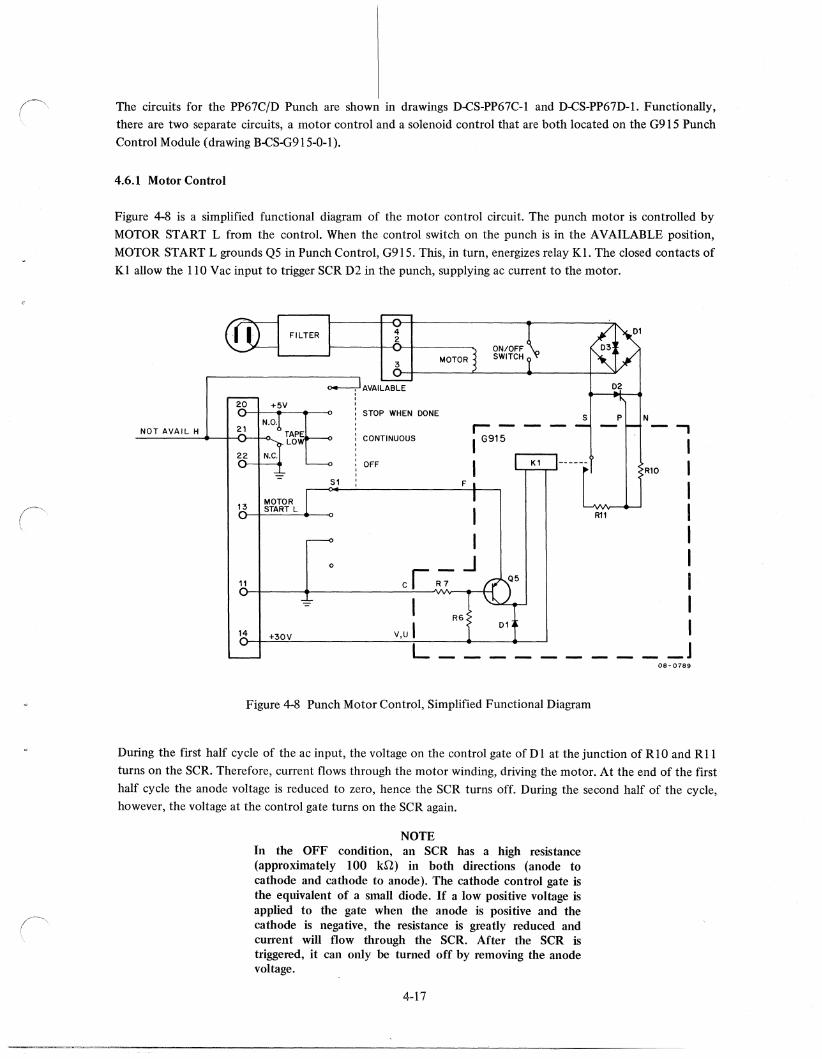
4.6.1 Motor Control
Figure 4-8 is a simplified functional diagram of the motor control circuit. The punch motor is controlled by
MOTOR START L from the control. When the control switch on the punch is in the AVAILABLE position,
MOTOR START L grounds QS in Punch Control, G9lS. This, in turn, energizes relay Kl. The closed contacts of KI allow the 110 Vac input to trigger SCR D2 in the punch, supplying ac current to the motor.
FILTER
20 +5V STOP WHEN DONE
P N N.O. NOT AVAIL H 21
TAPE r- I
LO CONTINUOUS I G915 I 22 OFF I R10 -= SI F I
I R11 I I I
0 .J I 11 ci ;;- Q5 I
-= I R6
I V,U I 01 14 +30V
L -- -- ---- _J 08-0189
Figure 4-8 Punch Motor Control, Simplified Functional Diagram
During the first half cycle of the ac input, the voltage on the control gate of D 1 at the junction of RIO and R 11
turns on the SCR. Therefore, current flows through the motor winding, driving the motor. At the end of the first
half cycle the anode voltage is reduced to zero, hence the SCR turns off. During the second half of the cycle, however, the voltage at the control gate turns on the SCR again.
NOTE In the OFF condition, an SCR has a high resistance (approximately 100 kn) in both directions (anode to cathode and cathode to anode). The cathode control gate is the equivalent of a small diode. If a low positive voltage is applied to the gate when the anode is positive and the cathode is negative, the resistance is greatly reduced and current will flow through the SCR. After the SCR is triggered, it can only be turned off by removing the anode voltage.
4-17
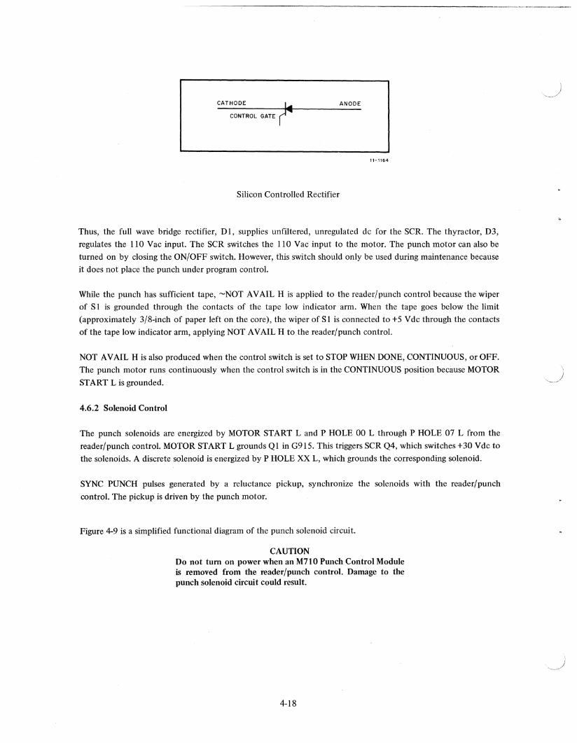
CATHODE r ANODE
CONTROL GATE
11-1164
Silicon Controlled Rectifier
Thus, the full wave bridge rectifier, Dl, supplies unfiltered, unregulated dc for the SCR. The thyractor, D3,
regulates the 110 Vac input. The SCR switches the 110 Vac input to the motor. The punch motor can also be
turned on by closing the ON/OFF switch. However, this switch should only be used during maintenance because
it does not place the punch under program control.
While the punch has sufficient tape, ~NOT AVAIL H is applied to the reader/punch control because the wiper
of S 1 is grounded through the contacts of the tape low indicator arm. When the tape goes below the limit
(approximately 3/8-inch of paper left on the core), the wiper of Sl is connected to +5 Vdc through the contacts
of the tape low indicator arm, applying NOT AVAIL H to the reader/punch control.
NOT AVAIL H is also produced when the control switch is set to STOP WHEN DONE, CONTINUOUS, or OFF.
The punch motor runs continuously when the control switch is in the CONTINUOUS position because MOTOR
START L is grounded.
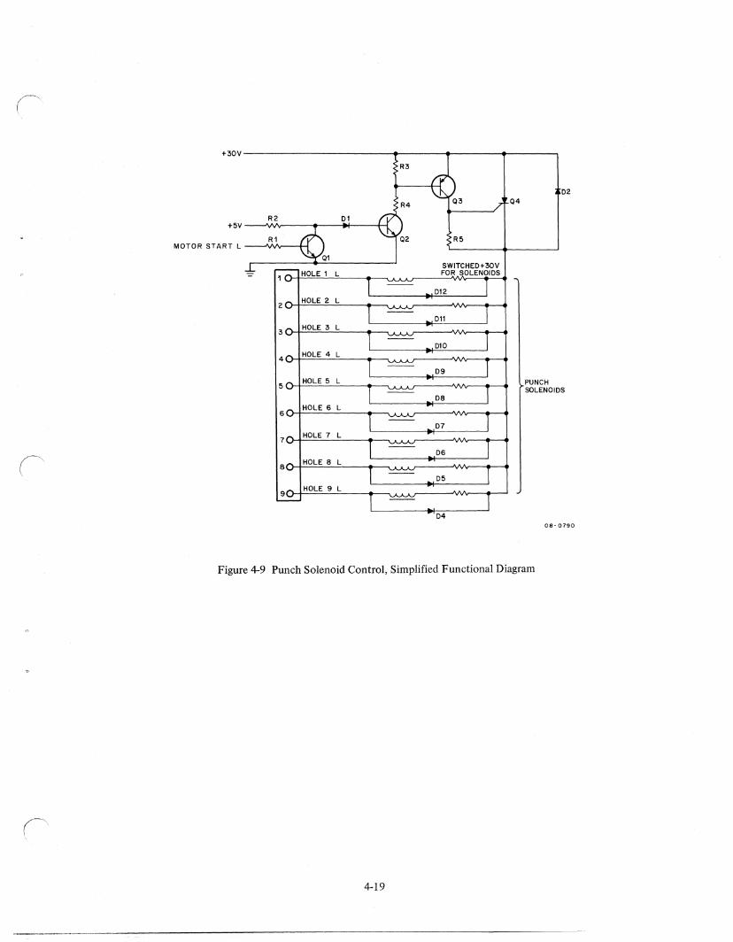
4.6.2 Solenoid Control
The punch solenoids are energized by MOTOR START Land P HOLE 00 Lthrough P HOLE 07 L from the
reader/punch control. MOTOR START L grounds Ql in G915. This triggers SCR Q4, which switches +30 Vdc to
the solenoids. A discrete solenoid is energized by P HOLE XX L, which grounds the corresponding solenoid.
SYNC PUNCH pulses generated by a reluctance pickup, synchronize the solenoids with the reader/punch
control. The pickup is driven by the punch motor.
Figure 4-9 is a simplified functional diagram of the punch solenoid circuit.
CAUTION Do not turn on power when an M710 Punch Control Module is removed from the reader/punch control. Damage to the punch solenoid circuit could result.
4-18
+30V--------------------------~--------._------~._------~
R3
D2 03 04
R1 R5 MOTOR START L
SWITCHED+30V FOR SOLENOIDS 10:
HOLE 1 L
D12
2 HOLE 2 L
Dll
3 HOLE 3 L
Dl0
4 HOLE 4 L
D9
PUNCH SOLENOIDS 5
HOLE 5 L
D8 HOLE 6 L
6
D7
'1 HOLE 7 L
D6
8 HOLE 8 L
D5
9 HOLE 9 L
D4 08-0790
Figure 4-9 Punch Solenoid Control, Simplified Functional Diagram
4-19
------------------------------

)
)
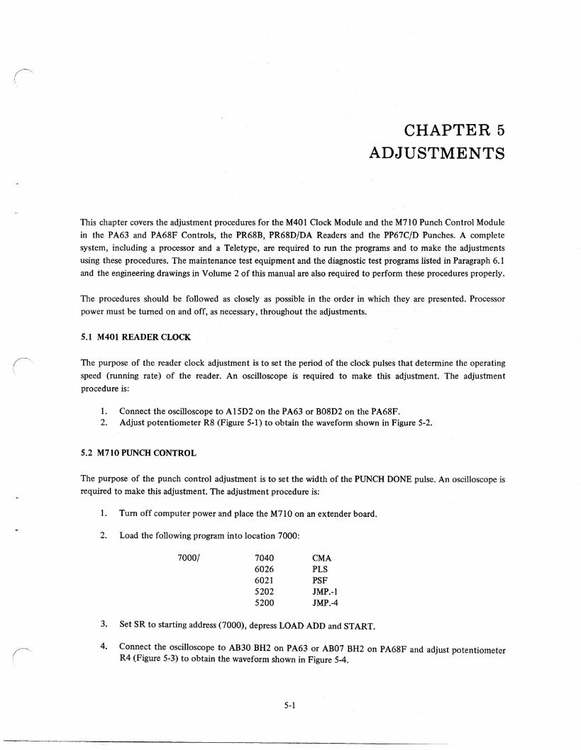
CHAPTER 5 ADJUSTMENTS
This chapter covers the adjustment procedures for the M401 Clock Module and the M710 Punch Control Module
in the PA63 and PA68F Controls, the PR68B, PR68D/DA Readers and the PP67C/D Punches. A complete
system, including a processor and a Teletype, are required to run the programs and to make the adjustments
using these procedures. The maintenance test equipment and the diagnostic test programs listed in Paragraph 6.1
and the engineering drawings in Volume 2 of this manual are also required to perform these procedures properly.
The procedures should be followed as closely as possible in the order in which they are presented. Processor
power must be turned on and off, as necessary, throughout the adjustments.
5.1 M401 READER CLOCK
The purpose of the reader clock adjustment is to set the period of the clock pulses that determine the operating
speed (running rate) of the reader. An oscilloscope is required to make this adjustment. The adjustment
procedure is:
1. Connect the oscilloscope to Al5D2 on the PA63 or B08D2 on the PA68F. 2. Adjust potentiometer R8 (Figure 5·1) to obtain the waveform shown in Figure 5-2.
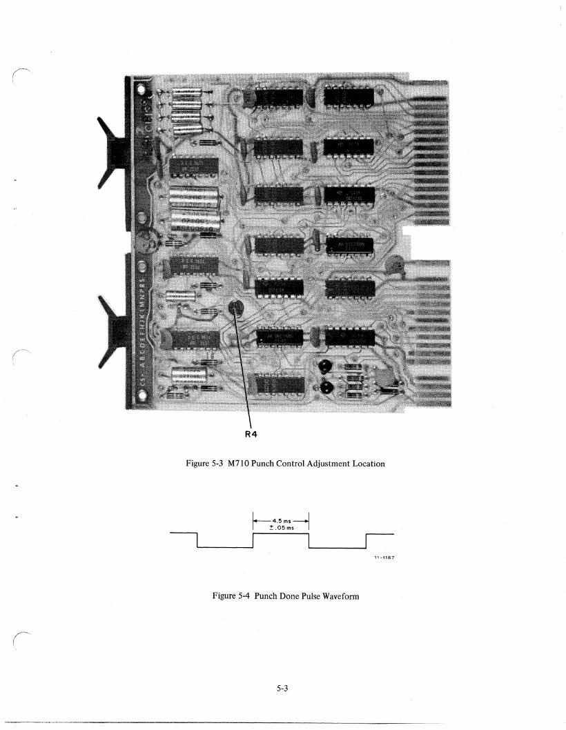
5.2 M710 PUNCH CONTROL
The purpose of the punch control adjustment is to set the width of the PUNCH DONE pulse. An oscilloscope is required to make this adjustment. The adjustment procedure is:
1. Tum off computer power and place the M710 on an extender board.
2. Load the following program into location 7000:
7000/ 7040 CMA 6026 PLS 6021 PSF 5202 JMP.-l 5200 JMP.-4
3. Set SR to starting address (7000), depress LOAD ADD and START.
4. Connect the oscilloscope to AB30 BH2 on PA63 or AB07 BH2 on PA68F and adjust potentiometer R4 (Figure 5-3) to obtain the waveform shown in Figure 5-4.
5-1
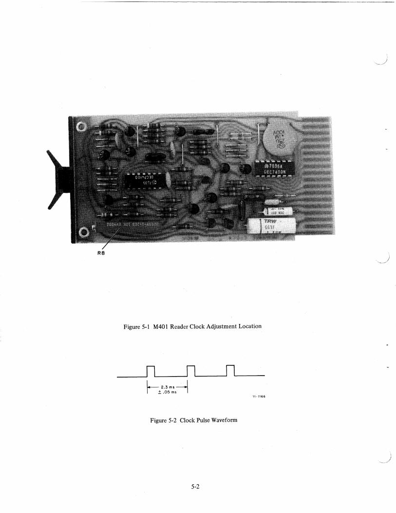
R8
Figure 5-1 M401 Reader Clock Adjustment Location
1- 2.3 ms . J 1±.05msl
Figure 5-2 Clock Pulse Waveform
5-2
11-1166
(" \
R4
Figure 5-3 M710 Punch Control Adjustment Location
11-1167
Figure 5-4 Punch Done Pulse Waveform
5-3
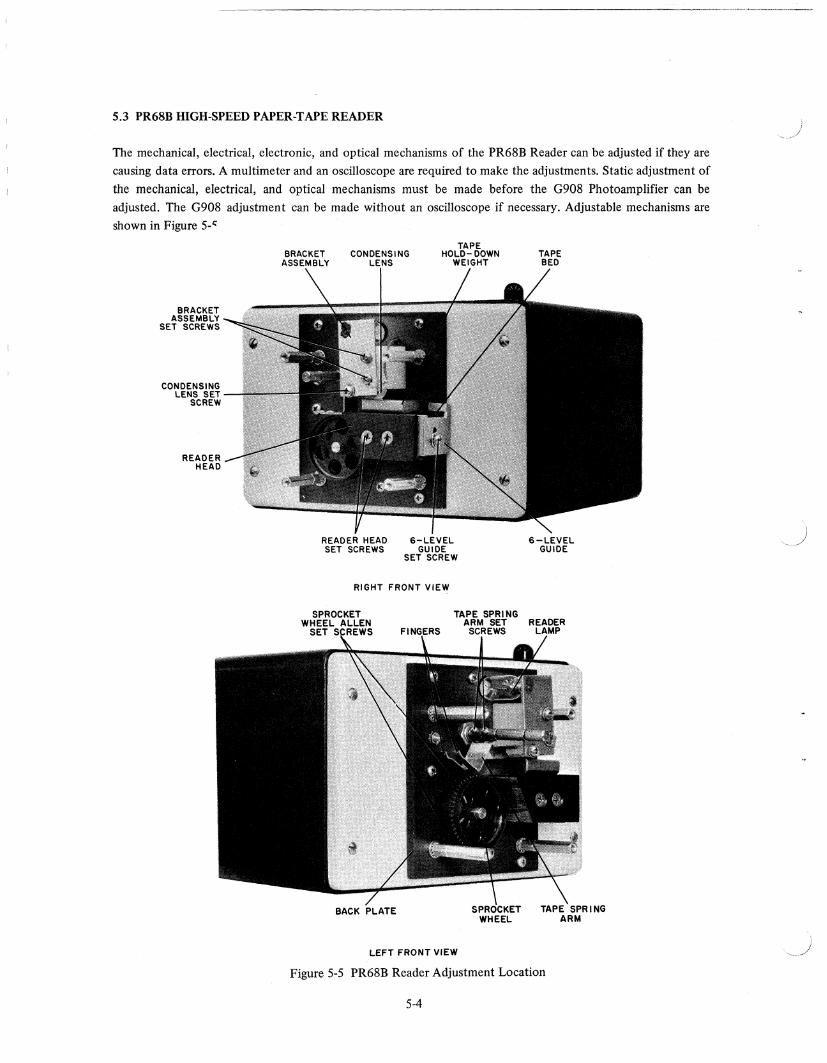
5.3 PR68B HIGH-SPEED PAPER-TAPE READER
The mechanical, electrical, electronic, and optical mechanisms of the PR68B Reader can be adjusted if they are
causing data errors. A multimeter and an oscilloscope are required to make the adjustments. Static adjustment of
the mechanical, electrical, and optical mechanisms must be made before the G908 Photoamplifier can be
adjusted. The G908 adjustment can be made without an oscilloscope if necessary. Adjustable mechanisms are
shown in Figure 5-'
BRACKET ASSEMBLY
SET SCREWS
CONDENSING LENS SET
SCREW
READER HEAD
CONDENSING
READER HEAD 6-LEVEL SET SCREWS GUIDE
SET SCREW
RIGHT FRONT VIEW
LEFT FRONT VIEW
6-LEVEL GUIDE
Figure 5-5 PR68B Reader Adjustment Location
5-4
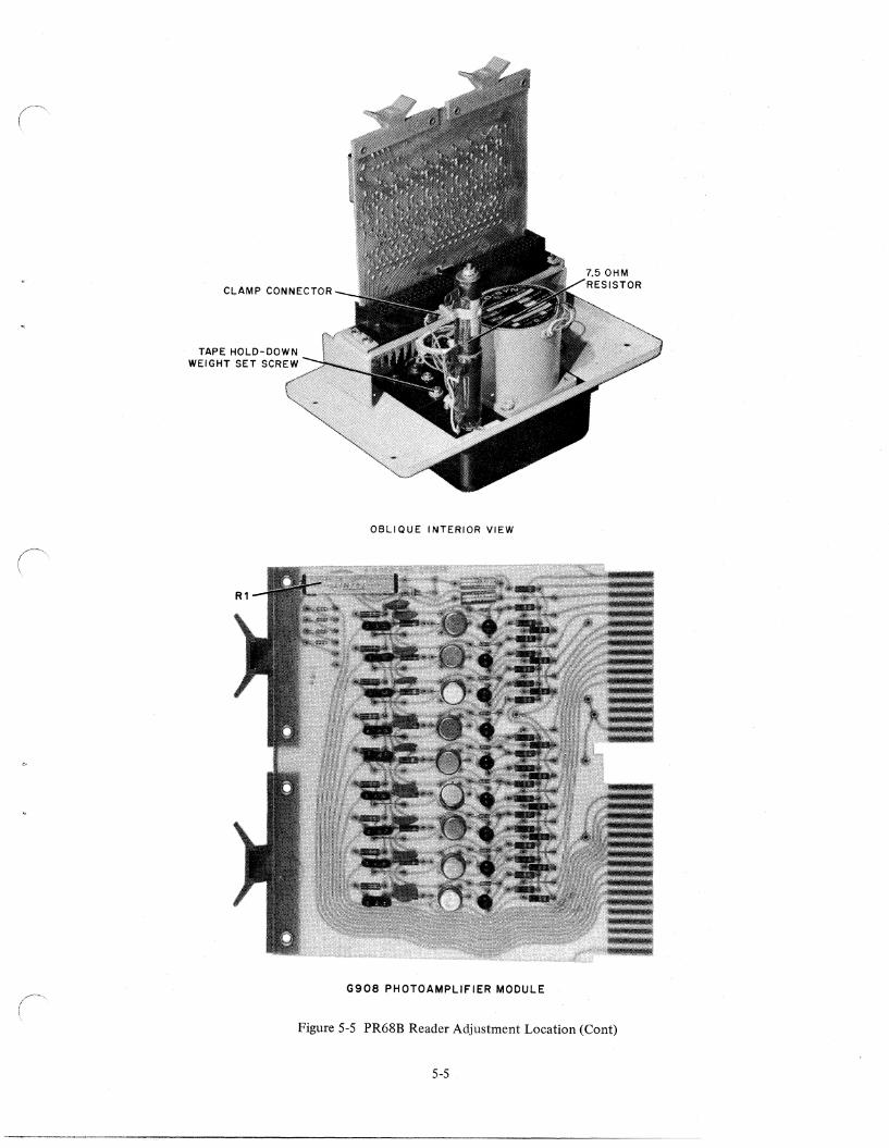
CLAMP CONNECTOR
OBLIQUE INTERIOR VIEW
G908 PHOTOAMPLIFIER MODULE ( \
Figure 5-5 PR68B Reader Adjustment Location (Cont)
5-5
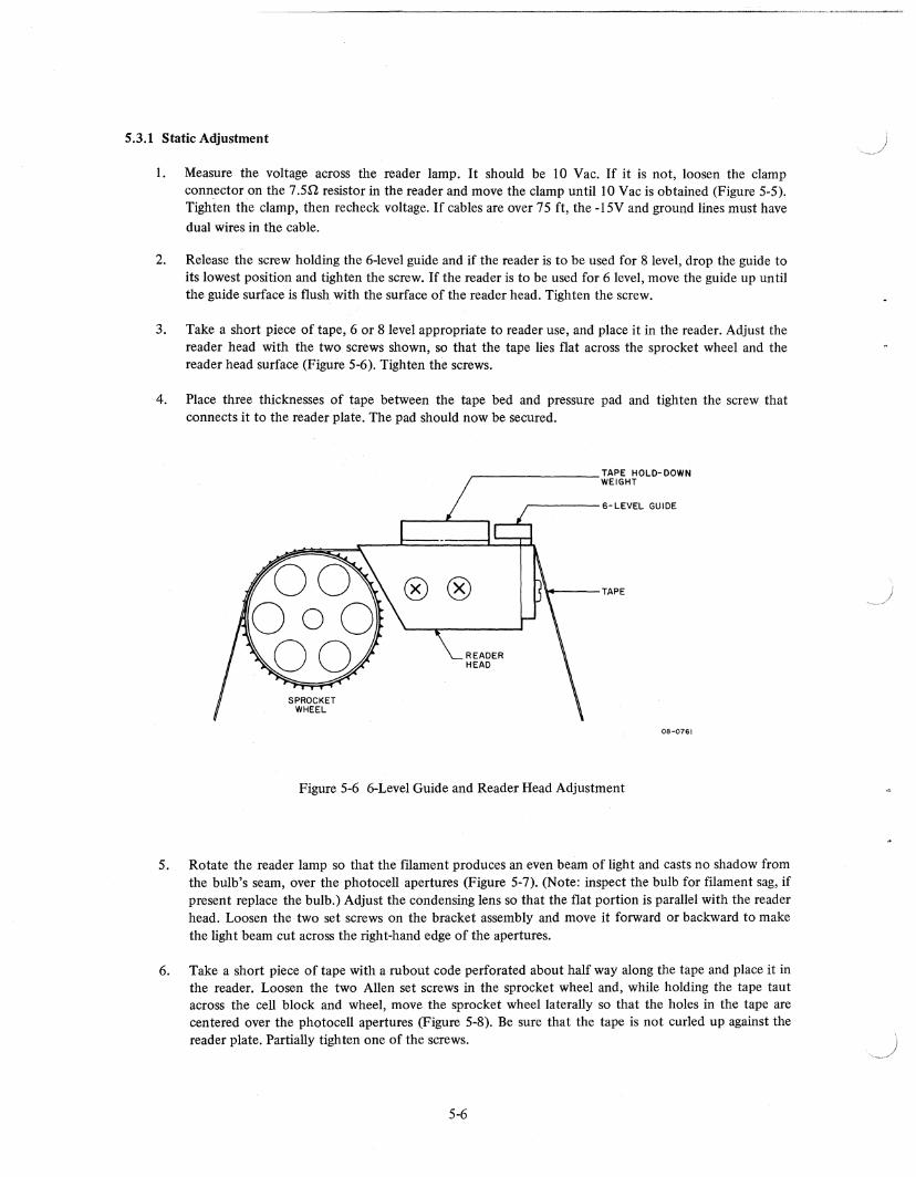
5.3.1 Static Adjustment
1. Measure the voltage across the reader lamp. It should be 10 Vac. If it is not, loosen the clamp connector on the 7.5[1. resistor in the reader and move the clamp until 10 Vac is obtained (Figure 5-5). Tighten the clamp, then recheck voltage. If cables are over 75 ft, the -15V and ground lines must have dual wires in the cable.
2. Release the screw holding the 6-level guide and if the reader is to be used for 8 level, drop the guide to its lowest position and tighten the screw. If the reader is to be used for 6 level, move the guide up until the guide surface is flush with the surface of the reader head. Tighten the screw.
3. Take a short piece of tape, 6 or 8 level appropriate to reader use, and place it in the reader. Adjust the reader head with the two screws shown, so that the tape lies flat across the sprocket wheel and the reader head surface (Figure 5-6). Tighten the screws.
4. Place three thicknesses of tape between the tape bed and pressure pad and tighten the screw that connects it to the reader plate. The pad should now be secured.
r-_______ ~~~H~OLD-DOWN
r-----6-LEVEL GUIDE
\4----TAPE
08-0761
Figure 5-6 6-Level Guide and Reader Head Adjustment
5. Rotate the reader lamp so that the mament produces an even beam of light and casts no shadow from the bulb's seam, over the photocell apertures (Figure 5-7). (Note: inspect the bulb for mament sag, if present replace the bulb.) Adjust the condensing lens so that the flat portion is parallel with the reader head. Loosen the two set screws on the bracket assembly and move it forward or backward to make the light beam cut across the right-hand edge of the apertures.
6. Take a short piece of tape with a rubout code perforated about half way along the tape and place it in the reader. Loosen the two Allen set screws in the sprocket wheel and, while holding the tape taut across the cell block and wheel, move the sprocket wheel laterally so that the holes in the tape are centered over the photocell apertures (Figure 5-8). Be sure that the tape is not curled up against the reader plate. Partially tighten one of the screws.
5-6
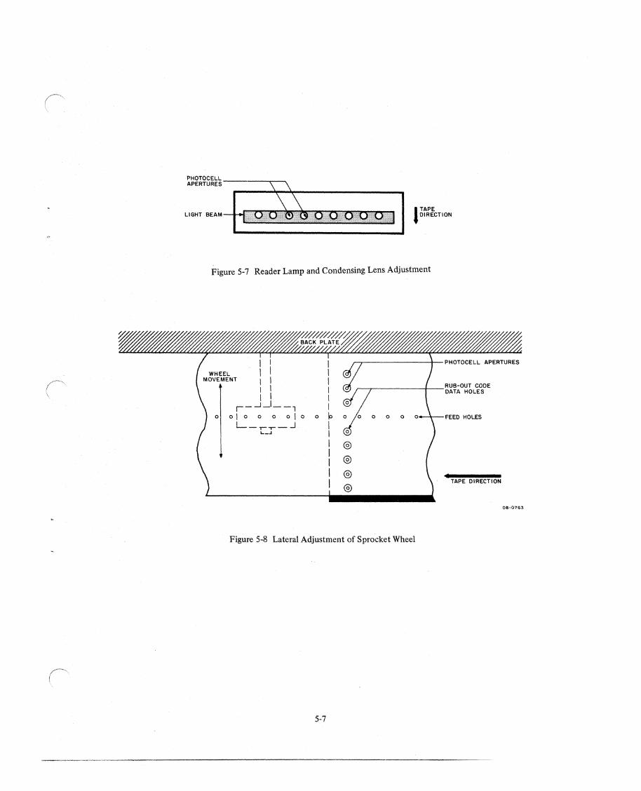
l TAPE DIRECTION
Figure 5-7 Reader Lamp and Condensing Lens Adjustment
o
I I
I 1
I I r-..J_I_-1
01000010
L_r--r_-.l L_J
I I I 1 1 I
o 10 I 1
I I I I I
@
@
o o o o-4--FEED HOLES
TAPE DIRECTION
Figure 5-8 Lateral Adjustment of Sprocket Wheel
5-7
08-0763
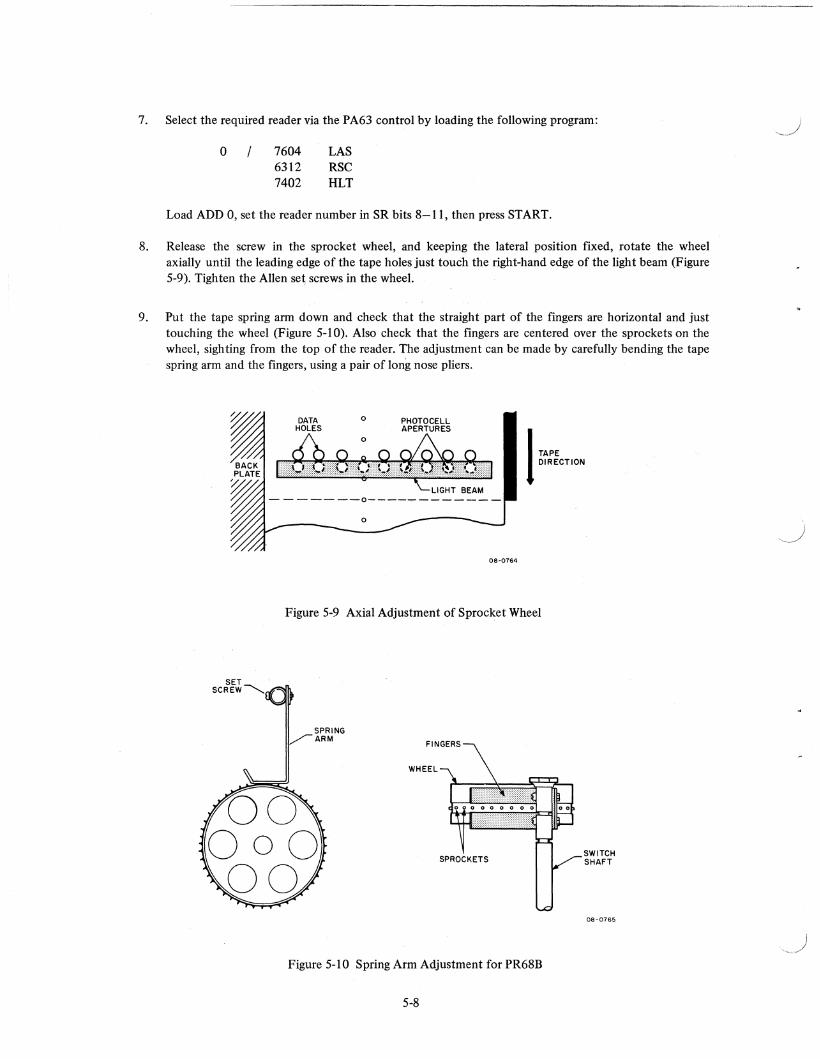
7. Select the required reader via the PA63 control by loading the following program:
o / 7604 LAS 6312 RSC 7402 HLT
Load ADD 0, set the reader number in SR bits 8-11, then press START.
8. Release the screw in the sprocket wheel, and keeping the lateral position fixed, rotate the wheel axially until the leading edge of the tape holes just touch the right-hand edge of the light beam (Figure 5-9). Tighten the Allen set screws in the wheel.
9. Put the tape spring arm down and check that the straight part of the fmgers are horizontal and just touching the wheel (Figure 5-10). Also check that the fingers are centered over the sprockets on the wheel, sighting from the top of the reader. The adjustment can be made by carefully bending the tape spring arm and the fingers, using a pair of long nose pliers.
DATA HOLES
o PHOTOCELL APERTURES
1 TAPE DIRECTION
08-0764
Figure 5-9 Axial Adjustment of Sprocket Wheel
SPRING ~ARM
Figure 5-10 Spring Arm Adjustment for PR68B
5-8
SWITCH SHAFT
08-0765
.,-)
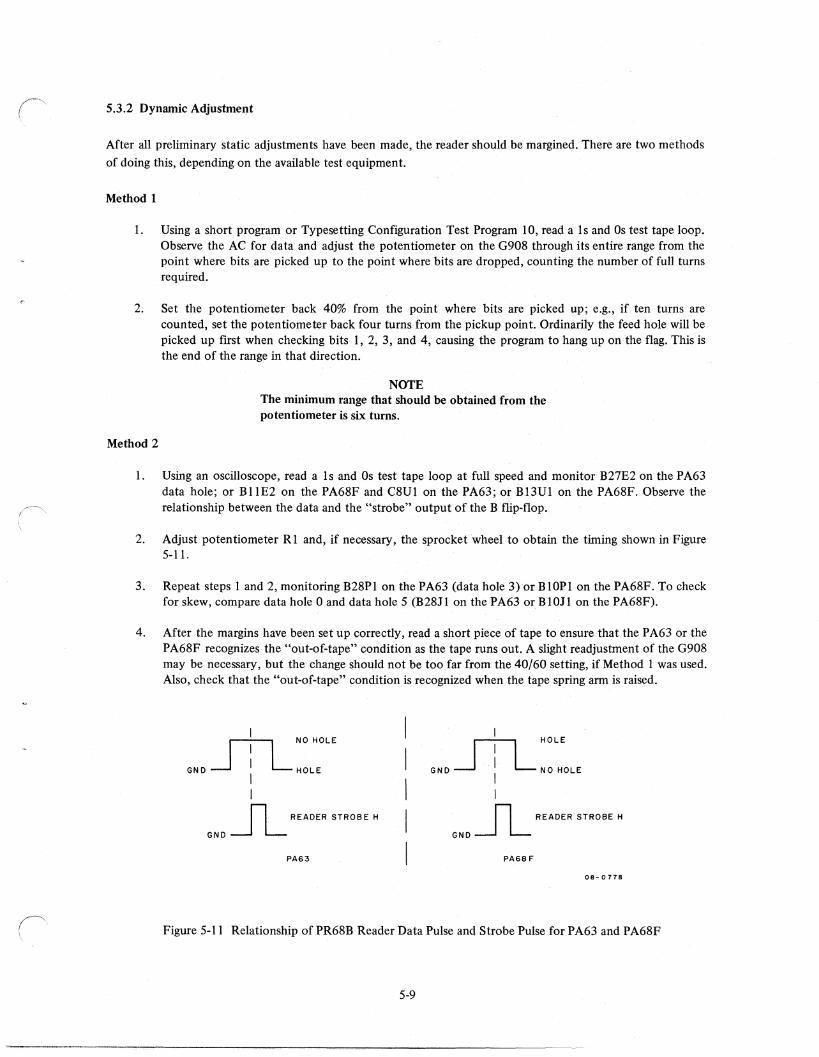
5.3.2 Dynamic Adjustment
After all preliminary static adjustments have been made, the reader should be margined. There are two methods
of doing this, depending on the available test equipment.
Method 1
1. Using a short program or Typesetting Configuration Test Program 10, read a Is and Os test tape loop. Observe the AC for data and adjust the potentiometer on the G908 through its entire range from the point where bits are picked up to the point where bits are dropped, counting the number of full turns required.
2. Set the potentiometer back 40% from the point where bits are picked up; e.g., if ten turns are counted, set the potentiometer back four turns from the pickup point. Ordinarily the feed hole will be picked up first when checking bits I, 2, 3, and 4, causing the program to hang up on the flag. This is the end of the range in that direction.
Method 2
NOTE The minimum range that should be obtained from the potentiometer is six turns.
1. Using an oscilloscope, read a Is and Os test tape loop at full speed and monitor B27E2 on the PA63 data hole; or BIIE2 on the PA68F and C8UI on the PA63; or Bl3Ul on the PA68F. Observe the relationship between the data and the "strobe" output of the B flip-flop.
2. Adjust potentiometer RI and, if necessary, the sprocket wheel to obtain the timing shown in Figure 5-11.
3. Repeat steps 1 and 2, monitoring B28Pl on the PA63 (data hole 3) or BIOP! on the PA68F. To check for skew, compare data hole 0 and data hole 5 (B28J 1 on the PA63 or B I OJ 1 on the PA68F).
4. After the margins have been set up correctly, read a short piece of tape to ensure that the P A63 or the PA68F recognizes the "out-of-tape" condition as the tape runs out. A slight readjustment of the G908 may be necessary, but the change should not be too far from the 40/60 setting, if Method 1 was used. Also, check that the "out-of-tape" condition is recognized when the tape spring ann is raised.
m NO HOLE
GND...J : L HOLE
I I
n READER STROBE H
GND --.J L PA63
I HOLE
'" JTl-" "'" I
n READER STROBE H
GND --.J L PA68F
08-0778
Figure 5-11 Relationship of PR68B Reader Data Pulse and Strobe Pulse for PA63 and PA68F
5-9
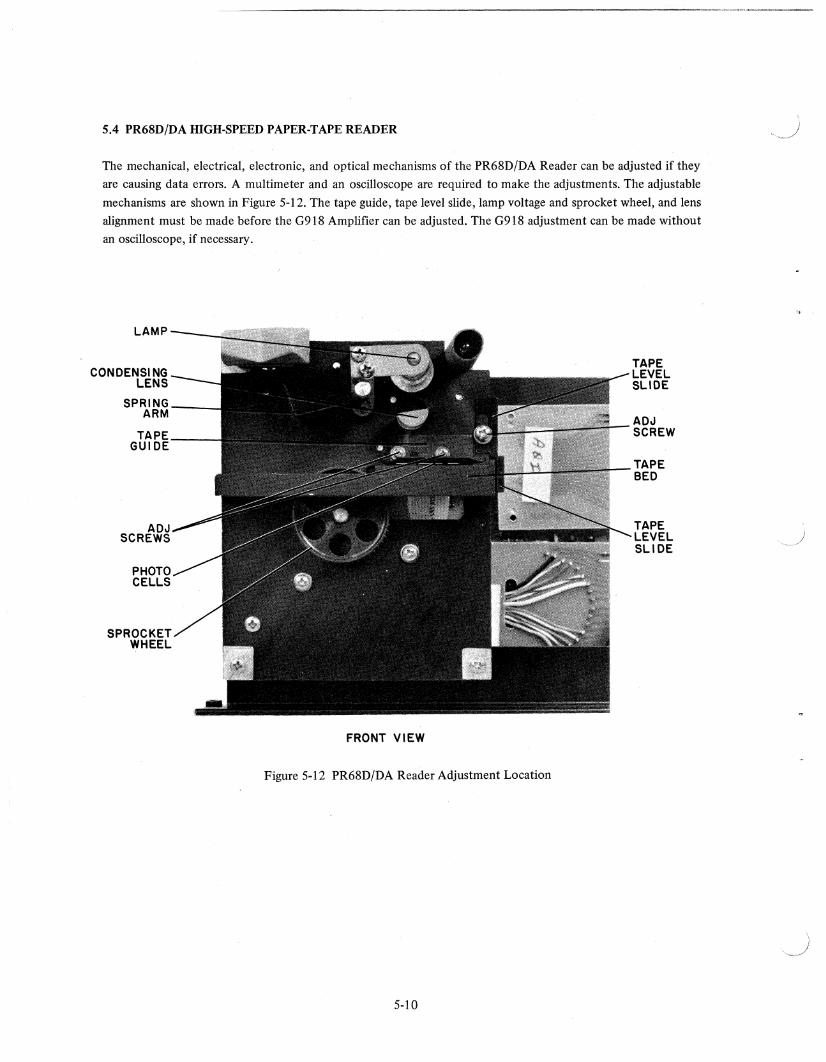
5.4 PR68D/DA HIGH-SPEED PAPER-TAPE READER
The mechanical, electrical, electronic, and optical mechanisms of the PR68D/DA Reader can be adjusted if they
are causing data errors. A multimeter and an oscilloscope are required to make the adjustments. The adjustable
mechanisms are shown in Figure 5-12. The tape guide, tape level slide, lamp voltage and sprocket wheel, and lens
alignment must be made before the G918 Amplifier can be adjusted. The G918 adjustment can be made without
an oscilloscope, if necessary.
LAMP
CONDENSING LENS
SPRING ARM
TAPE GUIDE
ADJ SCREWS
PHOTO CELLS
SPROCKET WHEEL
TAPE LEVEL SLIDE
ADJ SCREW
TAPE BED
TAPE LEVEL SLIDE
FRONT VIEW
Figure 5-12 PR68D/DA Reader Adjustment Location
5-10
I / ,-
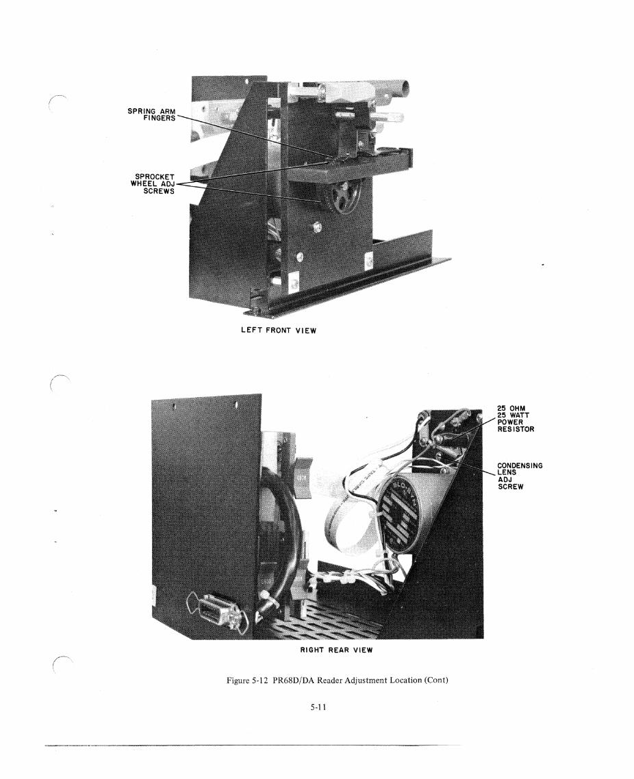
SPRING ARM FINGERS
SPROCKET WHEEL ADJ
SCREWS
LEFT FRONT VIEW
RIGHT REAR VIEW
Figure 5-12 PR68D!DA Reader Adjustment Location (Cont)
5-11
25 OHM 25 WATT POWER RESISTOR
CONDENSING LENS ADJ SCREW
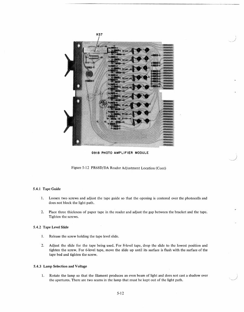
R37
G9t8 PHOTO AMPLIFIER MODULE
Figure 5-12 PR68D/DA Reader Adjustment Location (Cont)
5.4.1 Tape Guide
1. Loosen two screws and adjust the tape guide so that the opening is centered over the photocells and does not block the light path.
2. Place three thickness of paper tape in the reader and adjust the gap between the bracket and the tape. Tighten the screws.
5.4.2 Tape Level Slide
1. Release the screw holding the tape level slide.
2. Adjust the slide for the tape being used. For 8-level tape, drop the slide to the lowest position and tighten the screw. For 6-level tape, move the slide up until its surface is flush with the surface of the tape bed and tighten the screw.
5.4.3 Lamp Selection and Voltage
I. Rotate the lamp so that the filament produces an even beam of light and does not cast a shadow over the apertures. There are two seams in the lamp that must be kept out of the light path.
5-12
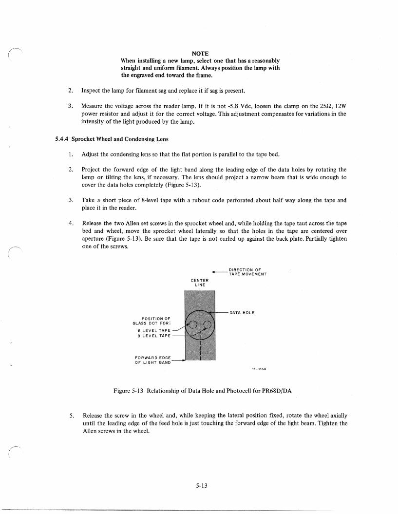
NOTE When installing a new lamp. select one that has a reasonably straight and uniform filament. Always position the lamp with the engraved end toward the frame.
2. Inspect the lamp for filament sag and replace it if sag is present.
3. Measure the voltage across the reader lamp. If it is not ·5.8 Vdc, loosen the clamp on the 25,Q, 12W power resistor and adjust it for the correct voltage. This adjustment compensates for variations in the intensity of the light produced by the lamp.
5.4.4 Sprocket Wheel and Condensing Lens
1. Adjust the condensing lens so that the flat portion is parallel to the tape bed.
2. Project the forward edge of the light band along the leading edge of the data holes by rotating the lamp or tilting the lens, if necessary. The lens should project a narrow beam that is wide enough to cover the data holes completely (Figure 5-13).
3. Take a short piece of 8-level tape with a rubout code perforated about half way along the tape and place it in the reader.
4. Release the two Allen set screws in the sprocket wheel and, while holding the tape taut across the tape bed and wheel, move the sprocket wheel laterally so that the holes in the tape are centered over aperture (Figure 5-l3). Be sure that the tape is not curled up against the back plate. Partially tighten one of the screws.
POSITION OF GLASS DOT FOR:
6 LEVEL TAPE 8 LEVEL TAPE
FORWARD EDGE OF LIGHT BAND
CENTER LINE
DIRECTION OF -TAPE MOVEMENT
DATA HOLE
11-1168
Figure 5-13 Relationship of Data Hole and Photocell for PR68D/DA
5. Release the screw in the wheel and, while keeping the lateral position fixed, rotate the wheel axially until the leading edge of the feed hole is just touching the forward edge of the light beam. Tighten the Allen screws in the wheel.
5-13
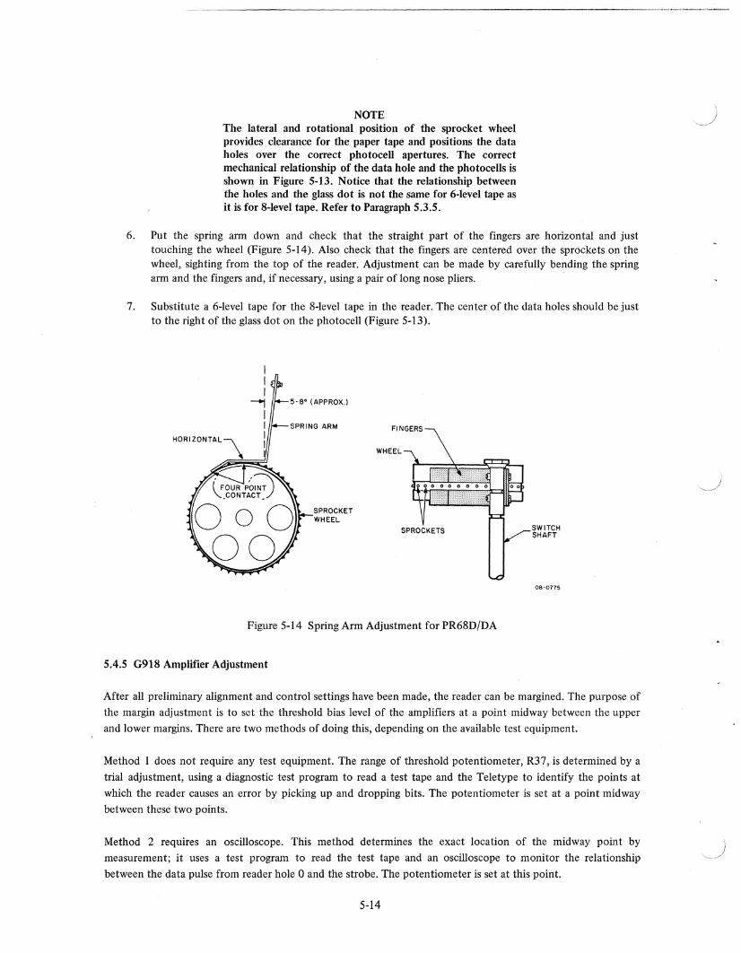
NOTE The lateral and rotational position of the sprocket wheel provides clearance for the paper tape and positions the data holes over the correct photocell apertures. The correct mechanical relationship of the data hole and the photocells is shown in Figure 5-13. Notice that the relationship between the holes and the glass dot is not the same for 6-level tape as it is for 8-level tape. Refer to Paragraph 5.3.5.
6. Put the spring arm down and check that the straight part of the fingers are horizontal and just touching the wheel (Figure 5-14). Also check that the fingers are centered over the sprockets on the wheel, sighting from the top of the reader. Adjustment can be made by carefully bending the spring arm and the fingers and, if necessary, using a pair of long nose pliers.
7. Substitute a 6-level tape for the 8-level tape in the reader. The center of the data holes should be just to the right of the glass dot on the photocell (Figure 5-13).
5-8 0 (APPROX.)
SPROCKET WHEEL
FINGERS
Figure 5-14 Spring Arm Adjustment for PR68D/DA
5.4.5 G918 Amplifier Adjustment
SWITCH SHAFT
08~0775
After all preliminary alignment and control settings have been made, the reader can be margined. The purpose of
the margin adjustment is to set the threshold bias level of the amplifiers at a point midway between the upper
and lower margins. There are two methods of doing this, depending on the available test equipment.
Method 1 does not require any test equipment. The range of threshold potentiometer, R37, is detennined by a
trial adjustment, using a diagnostic test program to read a test tape and the Teletype to identify the points at
which the reader causes an error by picking up and dropping bits. The potentiometer is set at a point midway
between these two points.
Method 2 requires an oscilloscope. This method determines the exact location of the midway point by
measurement; it uses a test program to read the test tape and an oscilloscope to monitor the relationship
between the data pulse from reader hole 0 and the strobe. The potentiometer is set at this point.
5-14
)
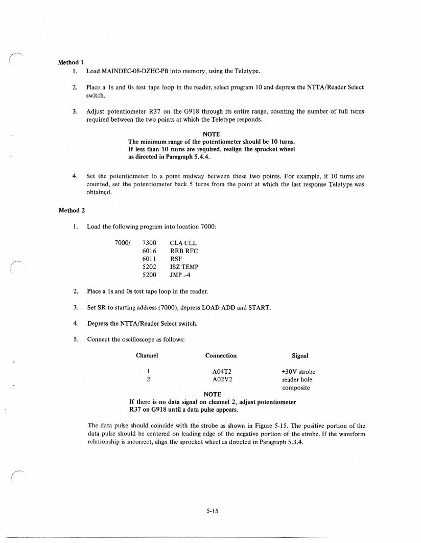
Method 1 1. Load MAINDEC-08-DZHC-PB into memory, using the Teletype.
2. Place a Is and Os test tape loop in the reader, select program 10 and depress the NTTA/Reader Select switch.
3. Adjust potentiometer R37 on the G918 through its entire range, counting the number of full turns required between the two points at which the Teletype responds.
NOTE The minimum range of the potentiometer should be 10 turns. If less than 10 turns are required, realign the sprocket wheel as directed in Paragraph 5.4.4.
4. Set the potentiometer to a point midway between these two points. For example, if 10 turns are counted, set the potentiometer back 5 turns from the point at which the last response Teletype was obtained.
Method 2
I. Load the following program into location 7000:
7000/ 7300 CLACLL 6016 RRB RFC 6011 RSF 5202 ISZ TEMP 5200 JMP .-4
2. Pla~e a Is and Os test tape loop in the reader.
3. Set SRto starting address (7000), depress LOAD ADD and START.
4. Depress the NTTA/Reader ~elect switch.
5. Connect the oscilloscope as follows:
Channel
2
Connection
A04T2 A02V2
NOTE
Signal
+30V strobe reader hole composite
If there is no data signal on channel 2, adjust potentiometer R37 on G918 until a data pulse appears.
The data pulse should coincide with the strobe as shown in Figure 5-15. The positive portion of the data pulse should be centered on leading edge of the negative portion of the strobe. If the waveform relationship is incorrect, align the sprocket wheel as directed in Paragraph 5.3.4.
5-15
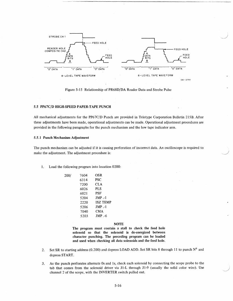
STROBE CH 1
"0" D'ATA "1" DATA "0" DATA "0" DATA "1" DATA "0" DATA
8- LEVEL TAPE WAVEFORM 6- LEVEL TAPE WAVEFORM
08-0791
Figure 5-15 Relationship ofPR68D/DA Reader Data and Strobe Pulse
5.5 PP67C/D HIGH-SPEED PAPER-TAPE PUNCH
All mechanical adjustments for the PP67C/D Punch are provided in Teletype Corporation Bulletin 2l5B. After
these adjustments have been made, operational adjustments can be made. Operational adjustment procedures are provided in the following paragraphs for the punch mechanism and the low tape indicator arm.
5.5.1 Punch Mechanism Adjustment
The punch mechanism can be adjusted if it is causing perforation of incorrect data. An oscilloscope is required to
make the adjustment. The adjustment procedure is:
1. Load the following program into location 0200:
200/ 7604 OSR 6314 PSC 7200 CLA 6026 PLS 6021 PSF 5204 JMP .-1 2220 ISZ TEMP 5206 JMP .-1 7040 CMA 5203 JMP .-6
NOTE The program must contain a stall to check the feed hole solenoid so that the solenoid is de-energized between character punching. The preceding program can be loaded and used when checking all data solenoids and the feed hole.
2. Set SR to starting address (0.200) and depress LOAD ADD. Set SR bits 8 through 11 to punch NO and
depress START.
3. As the punch perforates alternate Os and Is, check each solenoid by connecting the scope probe to the tab that comes from the solenoid driver via JI-L through 11-9 (usually the solid color wire). Use channel 2 of the scope, with the INVERTER switch pulled out.
5-16
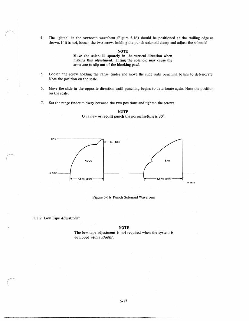
4. The "glitch" in the sawtooth wavefonn (Figure 5-16) should be positioned at the trailing edge as shown. If it is not, loosen the two screws holding the punch solenoid clamp and adjust the solenoid.
NOTE Move the solenoid squarely in the vertical direction when making this adjustment. Tilting the solenoid may cause the armature to slip out of the blocking pawl.
5. Loosen the screw holding the range finder and move the slide until punching begins to deteriorate. Note the position on the scale.
6. Move the slide in the opposite direction until punching begins to deteriorate again. Note the position on the scale.
7. Set the range finder midway between the two positions and tighten the screws.
NOTE On a new or rebuilt punch the normal setting is 30°.
GND---------------------~
- GLITCH
+30V---~
Figure 5-16 Punch Solenoid Waveform
5.5.2 Low Tape Adjustment
NOTE The low tape adjustment is not required when the system is equipped with a PA68F.
5-17
~.-".-""-~.~""-.-~---------------------------------
11-1170
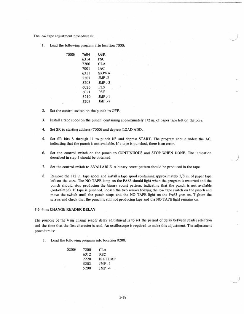
The low tape adjustment procedure is:
1. Load the following program into location 7000:
7000/ 7604 OSR 6314 PSC 7200 CLA 7001 lAC 6311 SKPNA 5207 IMP .2 5203 IMP .·3 6026 PLS 6021 PSF 5210 IMP .-1 5203 IMP .-7
2. Set the control switch on the punch to OFF.
3. Install a tape spool on the punch, containing approximately 1/2 in. of paper tape left on the core.
4. Set SR to starting address (7000) and depress LOAD ADD.
5. Set SR bits 8 through 11 to punch N° and depress START. The program should index the AC, indicating that the punch is not available. If a tape is punched, there is an error.
6. Set the control switch on the punch to CONTINUOUS and STOP WHEN DONE. The indication described in step 5 should be obtained.
7. Set the control switch to A V AILABLE. A binary count pattern should be produced in the tape.
8. Remove the 1/2 in. tape spool and install a tape spool containing approximately 3/8 in. of paper tape left on the core. The NO TAPE lamp on the PA63 should light when the pro~am is restarted and the punch should stop producing the binary count pattern, indicating that the punch is not available (out-of-tape). If tape is punched, loosen the two screws holding the low tape switch on the punch and move the switch until the punch stops and the NO TAPE light on the PA63 goes on. Tighten the screws and check that the punch is still not producing tape and the NO TAPE light remains on.
5.6 4 ms CHANGE READER DELAY
The purpose of the 4 ms change reader delay adjustment is to set the period of delay between reader selection
and the time that the first character is read. An oscilloscope is required to make this adjustment. The adjustment
procedure is:
1. Load the following program into location 0200:
0200/ 7200 CLA 6312 RSC 2220 ISZ TEMP 5202 IMP .-1 5200 IMP .-4
5-18
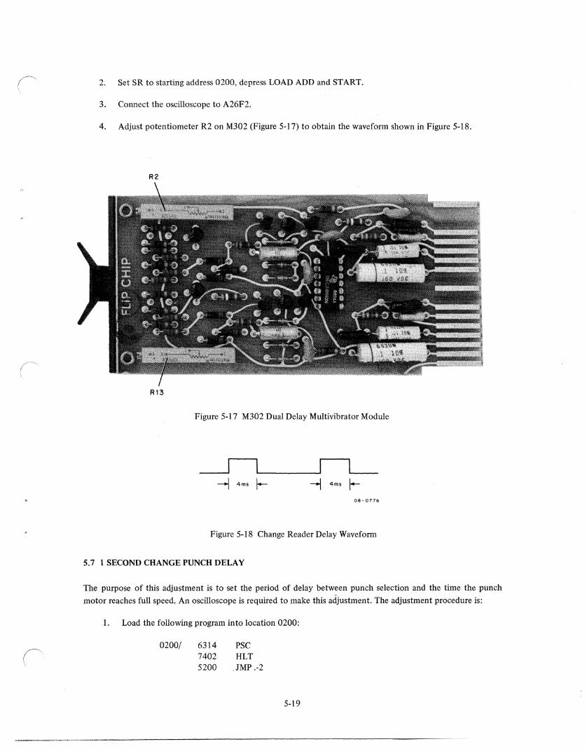
2. Set SR to starting address 0200, depress LOAD ADD and START.
3. Connect the oscilloscope to A26F2.
4. Adjust potentiometer R2 on M302 (Figure 5-17) to obtain the waveform shown in Figure 5-18.
R2
R13
Figure 5-17 M302 Dual Delay Multivibrator Module
~l'--_---JI 1,--_ ---l 4ms ~ -1 4ms f-
08- 0776
Figure 5-18 Change Reader Delay Waveform
5.7 1 SECOND CHANGE PUNCH DELAY
The purpose of this adjustment is to set the period of delay between punch selection and the time the punch
motor reaches full speed. An oscilloscope is required to make this adjustment. The adjustment procedure is:
1. Load the following program into location 0200:
0200/ 6314 PSC 7402 HLT 5200 ,JMP .-2
5-19
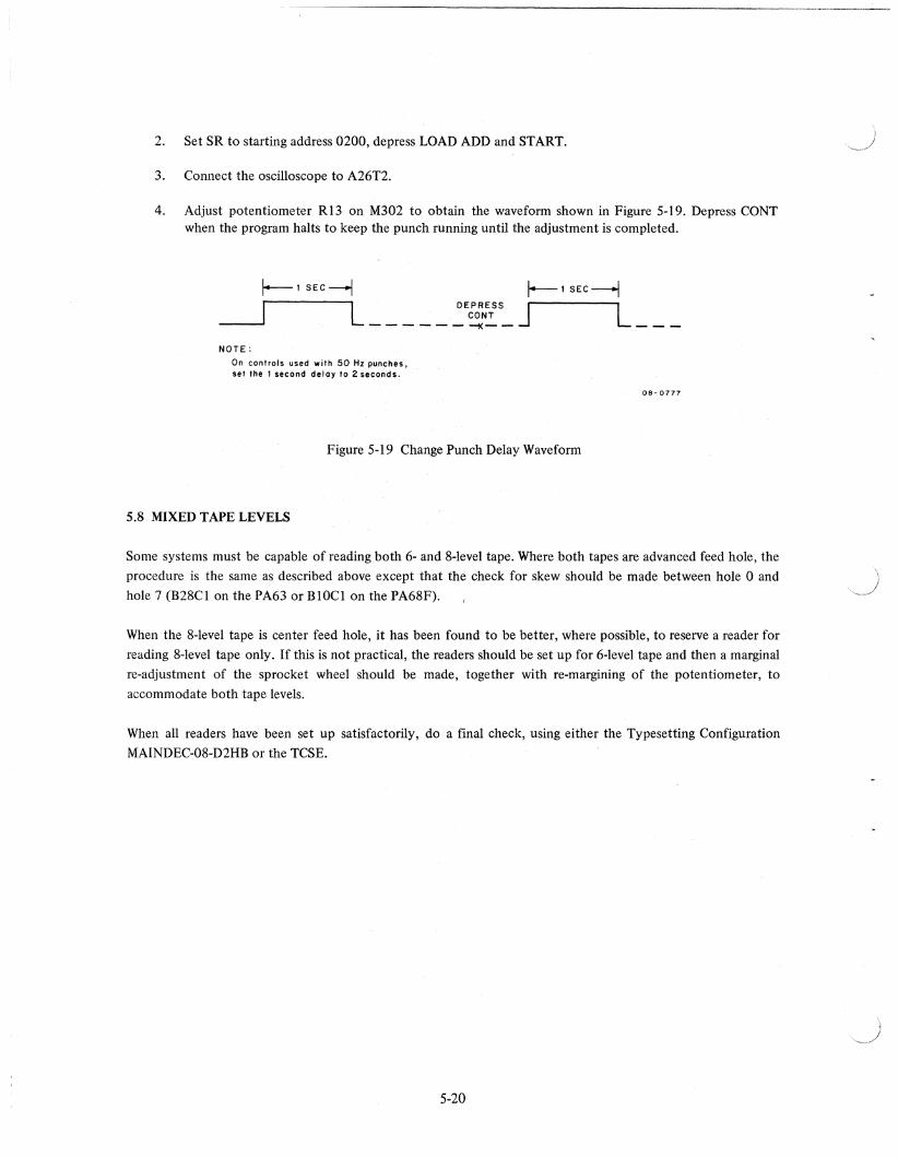
2. Set SR to starting address 0200, depress LOAD ADD and START.
3. Connect the oscilloscope to A26T2.
4. Adjust potentiometer R13 on M302 to obtain the waveform shown in Figure 5-19. Depress CaNT when the program halts to keep the punch running until the adjustment is completed.
1--1 SEC--j
I NOTE:
On controls used with 50 Hz punches. set the 1 second delay to 2 seconds.
Figure 5-19 Change Punch Delay Waveform
5.8 MIXED TAPE LEVELS
08 - 0777
Some systems must be capable of reading both 6- and 8-level tape. Where both tapes are advanced feed hole, the
procedure is the same as described above except that the check for skew should be made between hole 0 and
hole 7 (B28CI on the PA63 or BIOCI on the PA68F).
When the 8-level tape is center feed hole, it has been found to be better, where possible, to reserve a reader for
reading 8-level tape only. If this is not practical, the readers should be set up for 6-level tape and then a marginal
re-adjustment of the sprocket wheel should be made, together with re-margining of the potentiometer, to
accommodate both tape levels.
When all readers have been set up satisfactorily, do a final check, using either the Typesetting Configuration
MAINDEC-08-D2HB or the TCSE.
5-20
(' \
CHAPTER 6 MAINTENANCE
6.1 TEST EQUIPMENT AND DIAGNOSTIC PROGRAMS
The tools and test equipment required for testing and repairing the hardware are listed in Table 6-1.
Table 6-1
Test Equipment and Tools
Equipment Item Type
Test Equipment Oscilloscope Tektronix Model 453 (or equivalent) Volt-Ohmmeter
Devices Extender Boards One W985 double-extender board Two W980 single-extender boards
Tools ToolBox DEC Field Service Paper-Tape Gauge DEC Part No. 18-09211
The maintenance philosophy for Positive Logic Typeset-8 Systems is based on system checkout using test
programs and manual adjustments. The diagnostic programs supplied by DEC can be used to verify normal
operation of the hardware or to indicate possible causes of malfunction. These programs and the corresponding
documents are listed in Table 6-2.
Program Number
DEC-08-D2HC-PB DEC-08-D7CA-PB I DEC-08-D7CA-PB2
MAINDEC-X8-Module No.Rev. No. -PB
MAINDEC-08-D2UA-PB
Table 6-2
Diagnostic Programs
Document Number
DEC-08-D2HC-D DEC-08-DC7 A-D
MAINDEC-X8-DIQAB-A-D
MAINDEC"08-D2UA-D
6-1
Title
Family of 8 Typesetting Configuration Test Typeset-8 System Exerciser (TSCE)
Family of 8 Systems Exerciser
P A60C Diagnostic
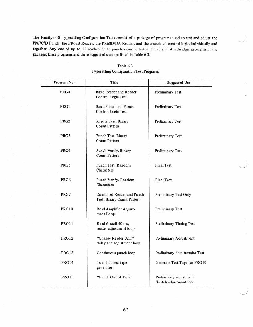
The Family-of-8 Typesetting Configuration Tests consist of a package of programs used to test and adjust the
PP67ClD Punch, the PR68B Reader, the PR68D/DA Reader, and the associated control logic, individually and
together. Anyone of up to 16 readers or 16 punches can be tested. There are 14 individual progrilms in the packllg~; these programs and there suggested uses are listed in Table 6-3.
Table 6-3 Typesetting Configuration Test Programs
Program No. Title Suggested Use
PRGO Basic Reader and Reader Preliminary Test Control Logic Test
PRGI Basic Punch and Punch Preliminary Test Control Logic Test
PRG2 Reader Test. Binary Preliminary Test Count Pattern
PRG3 Punch Test. Binary Preliminary Test Count Pattern
PRG4 Punch Verify. Binary Preliminary Test Count Pattern
PRGS Punch Test. Random Final Test Characters
PRG6 Punch Verify. Random Final Test Characters
PRG7 Combined Reader and Punch Preliminary Test Only Test. Binary Count Pattern
PRGlO Read Amplifier Adjust- Preliminary Test ment Loop
PRGll Read 6, stall 40 ms, Preliminary Timing Test reader adjustment loop
PRG12 "Change Reader Unit" Preliminary Adjustment delay and adjustment loop
PRG13 Continuous punch loop Preliminary data tramifer Test
PRG14 1 s and Os test tape Generate Test Tape for PRG 10 generator
PRGlS "Punch Out of Tape" Preliminary adjustment Switch adjustment loop
6-2
~
"~
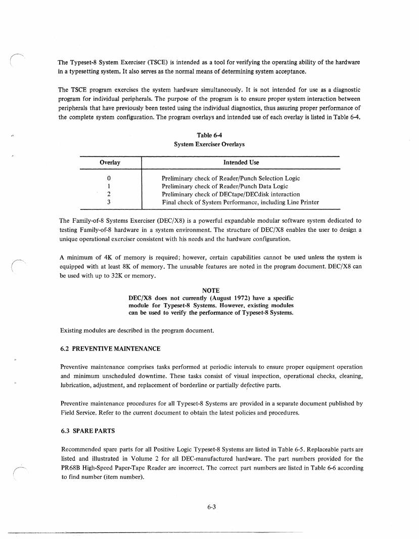
The Typeset-8 System Exerciser (TSCE) is intended as a tool for verifying the operating ability of the hardware
in a typesetting system. It also serves as the normal means of determining system acceptance.
The TSCE program exercises the system hardware simultaneously. It is not intended for use as a diagnostic
program for individual peripherals. The purpose of the program is to ensure proper system interaction between
peripherals that have previously been tested using the individual diagnostics, thus assuring proper performance of
the complete system configuration. The program overlays and intended use of each overlay is listed in Table 6-4.
Overlay
a 1 2 3
Table 6-4
System Exerciser Overlays
Intended Use
Preliminary check of Reader/Punch Selection Logic Preliminary check of Reader/Punch Data Logic Preliminary check of DECtape/DECdisk interaction Final check of System Performance, including Line Printer
The Family-of-8 Systems Exerciser (DEC/X8) is a powerful expandable modular software system dedicated to
testing Family-of-8 hardware in a system environment. The structure of DEC/X8 enables the user to design a
unique operational exerciser consistent with his needs and the hardware configuration.
A minimum of 4K of memory is required; however, certain capabilities cannot be used unless the system is
equipped with at least 8K of memory. The unusable features are noted in the program document. DEC/X8 can
be used with up to 32K or memory.
NOTE DEC/X8 does not currently (August 1972) have a specific module for Typeset-8 Systems. However, existing modules can be used to verify the performance of Typeset-8 Systems.
Existing modules are described in the program document.
6.2 PREVENTIVE MAINTENANCE
Preventive maintenance comprises tasks performed at periodic intervals to ensure proper equipment operation
and minimum unscheduled downtime. These tasks consist of visual inspection, operational checks, cleaning,
lubrication, adjustment, and replacement of borderline or partially derective parts.
Preventive maintenance procedures for all Typeset-8 Systems are provided in a separate document published by
Field Service. Refer to the current document to obtain the latest policies and procedures.
6.3 SPARE PARTS
Recommended spare parts for all Positive Logic Typeset-8 Systems are listed in Table 6-5. Replaceable parts are
listed and illustrated in Volume 2 for all DEC-manufactured hardware. The part numbers provided for the
PR68B High-Speed Paper-Tape Reader are incorrect. The correct part numbers are listed in Table 6-6 according
to find number (item number).
6-3
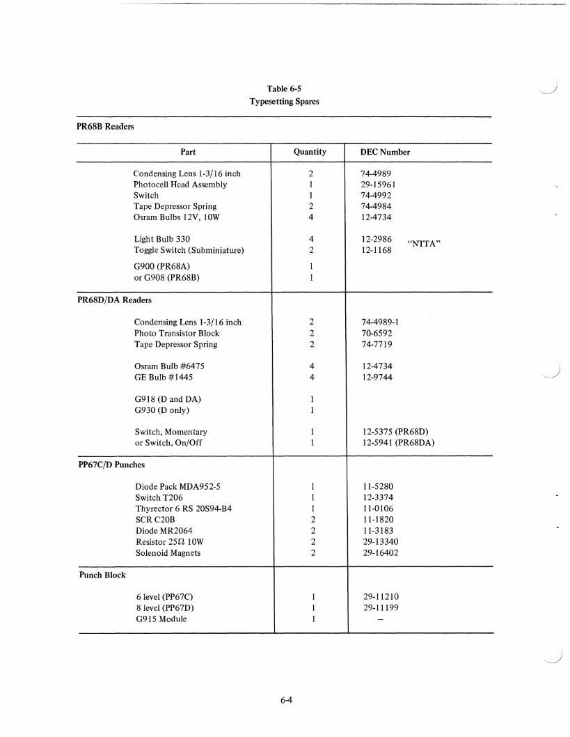
PR68B Readers
Part
Condensing Lens 1-3/16 inch Photocell Head Assembly Switch Tape Depressor Spring Osram Bulbs 12V, lOW
Light Bulb 330 Toggle Switch (Subminiature)
G900 (PR68A) or G908 (PR68B)
PR68D/DA Readers
Condensing Lens 1-3/16 inch Photo Transistor Block Tape Depressor Spring
Osram Bulb #6475 GE Bulb #1445
G918 (D and DA) G930 (D only)
Switch, Momentary or Switch, On/Off
PP67C/D Punches
Diode Pack MDA952-5 Switch T206 Thyrector 6 RS 20S94-B4 SCR C20B Diode MR2064 Resistor 25[1. lOW Solenoid Magnets
Punch Block
6 level (PP67C) 8 level (PP67D) G915 Module
Table 6-5
Typesetting Spares
Quantity
2 I I 2 4
4 2
I I
2 2 2
4 4
1 1
1 1
1 1 1 2 2 2 2
1 1 1
6-4
DEC Number
74-4989 29-15961 74-4992 74-4984 12-4734
12-2986 "NITA" 12-1168
74-4989-1 70-6592 74-7719
12-4734 12-9744
12-5375 (PR68D) 12-5941 (PR68DA)
11-5280 12-3374 11-0106 11-1820 11-3183 29-13340 29-16402
29-11210 29-11199
-
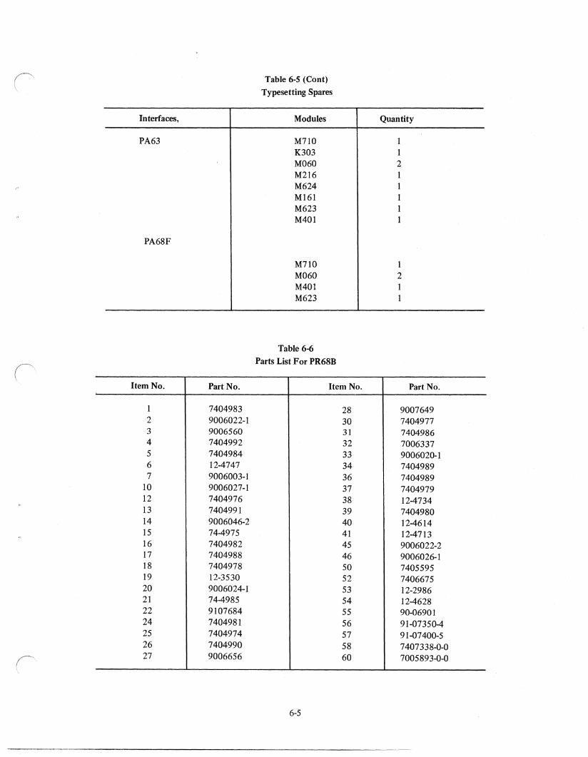
Table 6-5 (Cont) Typesetting Spares
Interfaces, Modules Quantity
PA63 M710 1 K303 1 M060 2 M216 M624 M161 M623 M401
PA68F
M710 1 M060 2 M401 M623
Table 6-6 Parts List For PR68B
Item No. Part No. Item No. Part No.
1 7404983 28 9007649 2 9006022-1 30 7404977 3 9006560 31 7404986 4 7404992 32 7006337 5 7404984 33 9006020-1 6 12-4747 34 7404989 7 9006003-1 36 7404989
10 9006027-1 37 7404979 12 7404976 38 12-4734 13 7404991 39 7404980 14 9006046-2 40 12-4614 15 74-4975 41 12-4713 16 7404982 45 9006022-2 17 7404988 46 9006026-1 18 7404978 50 7405595 19 12-3530 52 7406675 20 9006024-1 53 12-2986 21 74-4985 54 12-4628 22 9107684 55 90-06901 24 7404981 56 91-07350-4 25 7404974 57 91-07400-5 26 7404990 58 7407338-0-0 27 9006656 60 7005893-0-0
6-5

~.)
APPENDIX A GLOSSARY OF TERMS
The following pages contain a glossary of terms commonly used in the printing, graphic arts, and newspaper
fields. This glossary is designed to provide DEC maintenance personnel with a basic understanding of the term
inology used in these areas. Hopefully, this may lead to improved communication and a better understanding
of the problems encountered in those areas using the Typeset-8 System.
Agate line
Alterations
Ascender
Automatic allotting
Backing up
Bad break
Bands program
Base
Base line
Basis weight
Bearer
Benday
A standard of measurement for depth of columns of advertising space. Fourteen agate lines make one column inch.
In composition, changes made in the copy after it has been set in type.
That part of the letter which rises above the main body, as in "b".
Distribution of output tape codes to punches according to copy style.
Printing the reverse side of a sheet already printed on one side. In electrotyping, backing a copper shell with metal to make the plate the req uired thickness.
In composition, the setting of a hyphenated line as the first line of a page. Also, incorrect word division.
A program that uses space bands to justify lines of hot type.
In composition, all the metal below the shoulder of a piece of type. In letterpress, the metal or wood block on which printing plates are mounted to make them type high.
An imaginary line used as a reference in the measurement of leading. Alphanumeric characters sit on this line, descenders go below this line for example:
Quertyojp; p's are queueing for signatures.
The weight in pounds of a ream (500 sheets) of paper cut to a given standard size for that grade: 25 X 38 for book papers, 20 X 26 for cover papers, 22 1/2 X 28 1/2 or 22 1/2 X 35 for bristols, 25 1/2 X 30 1/2 for index, e.g., 500 sheets 25 X 38 of 80-1b coated will weigh eighty pounds.
In photoengraving, the dead metal left on a plate to protect the printing surface while molding. In composition, type-high slugs locked up inside a chase to protect the printing surface. In presses, the surface-to-surface ends of cylinders that come in contact with each other.
A method of laying a screen (dots, lines and other textures) on artwork or plates to obtain various tones and shadings.
A-I
Bite
Blanket
Blueprint·
Body
Bold-face type
Break for color
Bulk
Burnishing
Burr
Caliper
Caps and small caps
Carbro
Chase
Chicken plucker
Cold type
Collate
Combination plate
Column indent
Comet
Composing stick
Condensed type
Continuous tone
Copy
Curved plate
Cut
In photoengraving, the various stages of standard etching accomplished through the action of acid, the depth increasing after each bite.
In offset-lithography, a rubber-surfaced sheet clamped around the cylinder, which transfers the image from plate to paper.
In offset-lithography and photoengraving, a photoprint made from negatives or positives, used as a proof.
A term referring to the viscosity, consistency, or covering power of an ink or vehicle.
A name given to type that is heavier than the text type with which it is used.
In artwork and composition, to separate the parts to be printed in different colors.
The degree of thickness of paper.
In photoengraving, the corrective treatment of a printing plate to darken local areas by spreading the printing surface of lines and dots.
Rough edges of metal caused by routing or cutting.
The thickness of paper, usually expressed in thousandths of an inch.
Two sizes of capital letters made in one size of type, commonly used in most roman type faces.
A photograph in full color, frequently used for process color reproduction.
A rectangular metal frame in which type and plates are locked up for printing.
Small hand tool for modifying or correcting paper tape codes,
See photocomposition.
In binding, the assembling of sheets or signatures.
In photoengraving, halftone and line work combined on one plate; etched for both halftone and line depth.
A format in which all lines in a column are indented from the flush position.
Trade name line caster (See Electron)
In composition, a hand tool in which type is assembled and justified.
A narrow or slender type face.
A photographic image which has not been screened and contains gradient tones from black to white.
Any furnished material (typewritten manuscript, pictures, artwork) used in the production of printing.
In letterpress, an electrotype or sterotype which is backed up and precurved to fit the cylinder of a rotary press.
In letterpress, a photoengraving of any kind.
A-2
('
Cutscore
Densitometer
Descender
Display type
Distribution
Doctor blade
Dot
Double dot halftone
Drier
Dropout
Dummy
Duotone
Dump punch
Dropped rule
Electron
Electron mixer
Em
En
Engraving
In die-cutting, a sharp-edged knife, usually several thousandths of an inch lower than the cutting rules in a die, made to cut part way into the paper or board for folding purposes.
A sensitive photoelectric instrument which measures the density of photographic images, or of colors in color printing. Used in quality control to determine accurately whether color is consistent throughout the run.
That part of the letter which extends below the main body, as in "p".
In composition, type set larger than the text, used to attract attention.
In composition, the act of returning type, rules, leads, slugs, furniture, and other printing materials to their proper places after use.
In gravure, a knife-edge blade pressed against the engraved printing cylinder which wipes away the excess ink from the non-printing area.
The individual element of a halftone.
Two halftone negatives combined into one printing plate, having greater tonal range than a conventional halftone. One negative reproduces the highlights and shadows; the other reproduces middletones. Used primarily in offset-lithography.
In inkmaking, any substance added to hasten drying.
A halftone with no screen dots in the highlights.
A "preview" of a proposed piece of printing.
In photomechanics, a term for a two-color halftone reproduction from a one-color photograph.
A tape punch used to output a tape when the allotted punch cannot be used.
A straight type-high ruling slug often used to separate classified advertisements. See example beloW.
BABYSITTER: r:eeded. Oncp a weEK on Thursday 11 a.m. ~o 11 p,m. for coe 6 yr. old girl. AqE'ncy fee rate j:aid ..:. transportation. Ca.ll PL 54321 bet. 9
:; ~s;; E ::~:~g~t-"-'-dV----=-& -d:-.P-.o-'d.--;-b:-' •• short hours, 5 days j:pr wpek. Weekly salary_ Must have car. 791-8762.
BAB'YSIT'r~;eded - ni,;s.-s-days a week. J 15 . 12:30. Call 365-6605. [j'GiiT-hoJsekeeping & some C:lcking for elderly r::eJ;:)le. Live in. Lcs Altos. $150 month. 9.46-4598 or 812·7649.
Reprinted by permission of the Worcester Telegram and Gazette.
Trade name for a line caster similar to the Linotype; operates in the 6 to 9 pt range.
Same as Electron but capable of mixing up to four fonts in the 6 to 24-point range.
In composition, the square of a type body .. So named because the letter "M" in early fonts was usually cast on a square body.
One-half the width of an em.
A general term applied to any printing plate produced by an etching or cutting process.
A-3
Escapement
Etch
Expanded type
Face
Feeder
Filling in (or filling up)
Flat
Flow
Flush and Hang
Flush blocking
Flush left (or right)
Flush paragraph
Flying paster
Font
The distance that a carriage or lens mechanism moves for a character.
In photoengraving, to produce an image on a plate by chemical or electrolytic action. In offset-lithography, an acidified gum solution used to desensitize the non-printing areas of the plate; also, an acid solution added to the fountain water to help keep non-printing areas of the plate free from ink.
Type whose width is greater than normal; also called extended type.
The printing surface of a piece of type.
The section of a press which separates the sheets and feeds them in position for printing.
A condition in letterpress or offset-lithography where ink fills the area between the halftones dots or plugs up the type.
In offset lithography, the assembled composite of negatives or positives, ready for platemaking. Also, a picture that is lacking in contrast.
The ability of an ink to spread over a surface or into a thin film.
A printing format in which the first line of text is set flush with the left margin with all following lines indented. See example below.
A.M.
WSRS·FM WORCESTER-96.1 mcs
6:00~-ST~'REO AT DAYBREAK- Cl",us o 9 e r man; Ardre Kostclanef7.· Howard Roherts Quartet: An:'lor:y
Newley; Enoch Light; N"rf11al" Lvbaff Choir.
9:00-S-TEREO MAGIC: Tony Bennett; Edmur.do Ros; Peter Nero; Doris Day; Andre Koslelanetz; Ray CanniH.
P.M. 12:0Q--.STEREO SHOWCASE: Pctp.r
Nero; Matt Monro; Werner jv',ul· ler; Rodgers and Hart; Rar.n;", A:drich; Teresa Brewer; He;,r}' Mancini; 101 Strings; Enoch Light; Mel Davis.
5:00-STEREO SPECTRUM: Ar:dre Previ n; Jackie Gleason; ,~r.itc'l Bryant; George S:--earing; Maf"fovani; Edmundo R:>s.
8:OQ--SEST OF BROADWAY. Ray Conn.iff; Andre Previn; 101 Stri,1gs; Living Strirgs
lO:OO-TONIGHT ON POPS: Richard Tucker; A POj:s Concert with v:vi
ous artists; Eugene Ormandy; Athf'na.
12:00--STEREO TILL SIX: Living Trio: Hol:ywood Bowl Symphony; Glcl'1 Gray; Nat King Cole; Frar.kj~ Carle; Enoch Light; Bob E'Jerir and Helen O'Connell; E.~OC!us (~Jur.dtrack); Webley Edw .. rd~; Aret,ha Franklin; Cozy Cole; McGuire Sisters,
Reprinted by permission of the Worcester Telegram and Gazette.
Mounting a plate so that the printing surface is flush with the edge of the block.
In composition, type set to line up at the left (or right). This glossary of terms is set flush left.
A paragraph with no indention.
In web printing, an automatic pasting device that splices a new web of paper onto an expiring roll, without stopping the press.
A complete assortment of type of one size and face. In hot metal, a font is stored in a magazine. In photocomposition, a font is stored in a masking device such as a disk, film strip or grid; or digitized and stored on disks, in core memory, magnetic tape, etc., as in video display photocomposition machines.
A-4
)
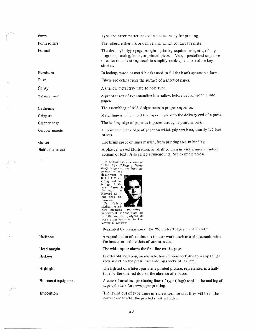
Form
Form rollers
Format
Furniture
Fuzz
Galley Galley proof
Gathering
Grippers
Gripper edge
Gripper margin
Gutter
Half-column cut
Halftone
Head margin
Hickeys
Highlight
Hot-metal equipment
Imposition
Type and other matter locked in a chase ready for printing.
The rollers, either ink or dampening, which contact the plate.
The size, style, type page, margins, printing requirements, etc., of any magazine, catalog, book, or printed piece. Also, a predefined sequence of codes or code strings used to simplify mark~up and or reduce keystrokes.
In lockup, wood or metal blocks used to fill the blank spaces in a form.
Fibers projecting from the surface of a sheet of paper.
A shallow metal tray used to hold type.
A proof taken of type standing in a galley, before being made up into
pages.
The assembling of folded signatures in proper sequence.
Metal fingers which hold the paper in place to the delivery end of a press.
The leading edge of paper as it passes through a printing press.
Unprintable blank edge of paper on which grippers bear, usually 1/2 inch or less.
The blank space or inner margin, from printing area to binding.
A photoengraved illustration, one-half column in width, inserted into a column of text. Also called a run-around. See example below.
Dr. Andras Fabry. a member of the Royal College of Veter· inary Surgeons, has been ap· pointed to the department of pharma cology and tox icology of M~· son Resear~h Institute, 21 Harvard St., it has been an· n~un:ed.
Dr. Fabry studied veteri. nary medicine Dr. Fabry in Liverpool, England, from 1956 to 1962. and did p')stgraduate werk anaesthetics at the Uni· versity of Glascow.
Reprinted by permission of the Worcester Telegram and Gazette.
A reproduction of continuous tone artwork, such as a photograph, with the image formed by dots of various sizes.
The white space above the first line on the page.
In offset-lithography, an imperfection in presswork due to many things such as dirt on the press, hardened by specks of ink, etc.
The lightest or whitest parts in a printed picture, represented in a halftone by the smallest dots or the absence of aU dots.
A class of machines producing lines of type (slugs) used in the making of type cylinders for newspaper printing.
The laying out of type pages in a press form so that they will be in the correct order after the printed sheet is folded.
A-S
Impression
Ink fountain
Insert
Intaglio printing
Justify
Kerning
Key
Key plate
Layout
Leaders
Leads
Leading
Letterspacing
Letter press
Linecasting machines
Linotype
Lockup
Logotype (or logo)
Long ink
Loose lines
Lower case
Ludlow
Magazine
Makeready
In printing, the pressure of type or plate as it comes in contact with the paper.
The container which supplies ink to the inking rollers.
A specially printed piece usually prepared for insertion in a publication.
Printing from plates in which the image is in intaglio or sunken below the surface, such as in steel-plate engraving or gravure.
In composition, to space out lines uniformly to the correct length.
Reduction of character escapement in order to condense words or lines of text-used primarily in conjunction with larger point sizes.
To code copy to a dummy by means of symbols, usually letters. Insertions are sometimes "keyed" in a like manner. In lockup, a device for operating quoins.
In color printing, the plate used as a guide for the register of other colors. It normally contains the most detail.
The drawing or sketch of a proposed printed piece.
In composition, rows of dashes or dots used to guide the eye across the page. Used in tabular work, programs, tables of contents, etc.
Thin strips of metal placed between lines of type to separate them vertically.
The amount of vertical space from baseline to base-in typeset copy.
The spacing between each letter of a word.
The process of printing directly from an inked raised surface upon which the paper is impressed.
Any of a group of keyboard and/or perforated-tape controlled devices which cast lines of lead type (slugs) using brass mats (matrices) as molds.
Trade name for a hot-metal line casting machine controlled from a keyboard or paper tape; operates in the 6 to 14 pt range.
In letterpress, to position a form in a chase for printing.
Name of a company or product in a special design used as a trademark in advertising.
An ink that has good flow in the fountain.
Lines in which the total width of the mats used is less than the preset line length. When this occurs, the linecaster will not mold a slug.
The small letters in type, as distinguished from the capital (upper case) letters.
Trade name for a manually operated linecaster which produces type slugs from hand-set type mats.
In hot-metal typecasting equipment, a container, usually mounted at the top of the equipment, from which type-molding mats are automatically drawn to produce type slugs.
In letterpress, the building up of the press form so that heavy and light areas print with the correct impression.
A-6
Makeup
Mask
Masking paper
Mat
Matrix
Measure
Middletones
Mixing
Moire
Mottle
Newsprint
NickeJtype
No-Bands program
Offset printing
Opaque
In composition, the arrangement of lines of type and illustrations into pages of proper length.
In color separation photography, an intermediate photographic negative or positive used in color correction. In offset-lithography, opaque material used to protect open or selected areas of printing plates during exposure.
In offset-lithography, goldenrod paper to which negatives are fastened in stripping to produce a flat.
Newspaper term for a matrix.
A mold in which type is cast in linecasting machines. In stereotyping, the paper mold made from a type form.
In composition, the width of type, usually expressed in picas.
The tonal range between highlights and shadows of a photograph or reproduction.
The process by which mats are drawn from different magazines on a single linecaster to produce distinctive printing formats; as in advertisements. See example of four-magazine mixing below.
Air Conditioning Ventilation
Heating CUSTOM DESIGNED FOil
YOUII NEEDS by PIIOFESSIONALS
ABO OORP. 123 ~y St., Melbourne
51'·3341 Servo The County OYer 29 Years
Reprinted by permission of the Worcester Telegram and Gazette.
Undesirable screen pattern in color process printing caused by incorrect screen angles of halftones.
The spotty or uneven appearance of printing. Most pronounced in solid areas.
A generic term used to describe the kind of paper generally used in the publication of newspapers.
In electrotyping, a plate on which the first deposit is of nickel and the remainder of the shell is copper. Nickeitypes give sharper definition in printing and are more durable than copper.
A program that uses fixed spacing and the auto-quadding features of a line caster to justify lines of hot type.
A printing process in which an inked impression from a planographic surface is first made on a rubber-blanketed cylinder and then transferred to the paper being printed.
In photoengraving and offset-lithography, to paint out areas on a negative not wanted on the plate. In paper, the property which makes it less transparent.
A-7
Overlay
Overprinting
Overset
Paragraph indent
Pasteup
Patent base
Perfecting press
Photocomposition
Photocomposition machine
In letterpress makeready, a piece of paper placed in the packing to make that part of the form print more heavily. In artwork, a transparent or translucent covering over copy where color break, instructions, or corrections are marked.
Double printing; printing over an area that already has been printed.
In composition, type set in excess of space needs in publications.
A format in which the initial line of a paragraph is indented with the balance of lines flush left.
The preparation of copy for photographic reporduction by putting all elements in the proper position.
In letterpress, a slotted metal base on which unmounted electrotypes are secured.
A press which prints both sides of paper at one time.
A process by which reproducible page masters are photographically produced.
A device that produces and composes type photographically. See following:
C/A/T - Used for on-line text and limited display composition with direct computer drive; operating range is 6 to 36 pt in IS sizes. It contains four completely independent font segments at a time. Each font contains up to 102 characters ..
Compugraphic 4962 - Used for mixed text and display composition. Type can be set from a film strip containing four 90-character fonts.
Compstar 191 - Used for high-speed text and display composition; operates in the 5 1/2 to 48 pt range. Machine has eight lenses and a dual lensing feature that produces 15 point sizes.
Fototronic 480/1200 - Text and display composition. Type Sizes range from 5 to 72 pt depending upon disk size, in 19 sizes. Each type disk contains two, 120-character fonts, with five disks on the machine at one time. Font capacity leaves 30 extra locations for storing pi characters, accents, or other special characters.
Fototronic TxT - Similar to the Fototronic 480/1200. The differences are:
I. It is primarily a text-oriented machine with some display capabilities. Type size range is from 5 to 36 pts in 15 sizes.
A-8
2. It uses a l2-position lens turret that puts up to 12 sizes of type on a line at the same time, instead of the zoom lens optical system used in the 480/1200.
3. Light source is an xenon lamp instead of a plasma jet.
Photon 513 - Used in display composition; operates in the 6 to 72 pt range.
Photon 532 - Computer slave used in text and display composition; operates in the 4 1/2 to 72 pt range, in 23 sizes from two matrix disks containing 32 90-character type faces (16 per disk).
Photon 560 - Similar to the 513.
Photon 561 - Similar to the 532. The 561 has only one glass matrix disk instead of two. It holds 16 90-character typefaces rather than 32. It can produce 12 type sizes for each face from the lens turret which does not have the minifier lens that gives the 532 23 sizes. Type size range is 5 to 72 pts.
Photon 713-5 - Used in text and limited display composition; operates in the 5 to 18 pt range, with two sizes and four faces. A single film strip contains four 96-character fonts.
Photon 713-10 - Used in straight text and limited display composition; operates in 5 to 36 pt range, with font strips carrying 8 96-character type faces in 8 sizes. Strips can be arranged singly or in duplexed pairs.
Photon 713-20 - Similar to 713-10.
Photon 713-100 - Similar to 713-10, but faster.
Photon 713-200 - Similar to 713-100, but even faster. It has a 4K minicomputer for memory.
Pacesetter - Used in high-speed text and display composition. Operates in 5 to 72 pt range. The number of typefaces and sizes depends on the model, e.g., Pacesetter 45 has four faces in five sizes. Customer selects up to 16 sizes, depending on specific requirements. A fully programmab Ie 8K mini-computer provides the control logic and gives the Pacesetter far greater format storage capacity than the 713 series.
Linofilm - Used in text and display composition. Operates in the 6 to 54 pt range in five grid ranges. Enlargement and reduction capabilities extend the range from 4 to 216 points. Each grid contains 88 characters.
Linofilm Quick - Used in straight text compositon; operates in the 6 to 18 pi range.
Linofilm Superquick - There are three versions of this machine; two standard models and a wide range model. Standard models are available in two or four-grid configurations; operating range is 5 to 18 pt. The wide-range model has four grids with an operating range from 5 to 72 pts, making it both a text and display composition machine.
V-I-P - Primarily a text composition machine; operates in the 6 to 48 pt range. It can mix up to 6 96-character fonts in 16 sizes. A display attachment extends the range to 96 pts.
A-9
Pi
Pica
Pica pole
Picking
Piling
Point
Primary colors
Process printing
Progressive proofs
Quad
Quoin
Register
Register marks
Reproduction proof
Reverse plate
Routing
Sans-serif
Scale
Scanner
Score
Screen
Serif
Set-off
Type mixed and in an unusable condition.
Printer's unit of measurement used principally in measuring lines. One pica equals 1/6 of an inch.
See type gauge.
The lifting of the paper surface during printing. It occurs when pulling force (tack) of ink is greater than surface strength of paper.
The building up or caking of ink on rollers, plate or blanket; will not transfer readily.
Printer's unit of measurement, used principally for designating type sizes. There are 12 points to a pica; 72 points to an inch.
In printing inks, yellow, magenta (process red) and cyan (process blue). In light, the primary colors are red, green, and blue.
The printing from a series of two or more halftone plates to produce intermediate colors and shades. Usually in four-color process: yellow, red, blue, and black.
Proofs of each individual plate in a set of color process plates, pulled in the proper colored inks, and also showing the results of adding each color.
In composition, blank spacing material less than type high used to fill out lines.
In letterpress, steel wedge-shaped or expanding devices used in lockup.
Fitting of two or more printing images upon the same sheet of paper in exact alignment with each other.
Crosses or other devices applied to original copy prior to photography. Used for positioning negatives in perfect register, or for color register of two or more colors in printing.
In composition, the proof of a type form for photographic reproduction.
A printing plate in which the parts that are usually black or shaded are reversed, so as to appear white or grey.
Cutting away the non-printing areas of a letterpress plate.
A typeface having no serifs.
The proportion between dimensions of an original and its reproduction. Degree of enlargement or reduction.
Electronic device designed to read typewritten copy optically.
To impress or indent a mark with a string or rule in the paper to make folding easier.
In photoengraving and offset-lithography, glass or film with cross-ruled opaque lines or vingnetted dots used to reporduce continuous tone artwork such as photographs. Also, the number of lines or dots to the linear inch on printed illustration.
The short cross-lines at the ends of the main strokes in roman type faces.
In presswork, when the ink of a printed sheet rubs off or marks the next sheet as it is being delivered. Formerly called offset.
A-IO
Set size
Shadow
Short ink
Signature
Slitting
Slug
Small caps
Space band
Stet
Straight matter
Strike-through
Stripping
Substance
An increase or decrease in character escapement to expand or condense words or lines of text.
The darkest parts in a photograph, represented in a halftone by the largest dots.
An ink that does not flow freely.
In book, magazine and catalog work, the name given to a large printed sheet after it has been folded to the required size.
Cutting printed sheets or webs into two or more sections by means of cutting wheels on the press or folding machine.
In composition, a one-piece line of type. Also a strip of metal, usually 6 points, used for spacing.
An alphabet of small capital letters available in most roman type faces approximately the size of the lower case letters. Used in combination with larger capital letters.
A unit of two thin wedge-shaped pieces of metal used as spacers between the words of a line of hot type. Expandable from approximately a thin space to an En space plus a thin space.
A proofreader's mark, written in the margin, signifying that copy previously marked for corrections should stand as printed and not be corrected.
Columns of printing containing continuous text matter using the same type style and size. See example below.
The Worcester Chapter of the Administrative Management Society. will hold "E:luc"tion Night" tomorrow at 6:45 p.m. in the Coach and Six R :staurant.
Highligi:ting the even;ng's activitie:; will be the award"ing of a scholarship to a Worce'ster area high school student. a panel discus3ion on "How Are We Preparing Our Young Pecple For Business'?", and installation of new officers for the earning" year.
Reprinted by permission of the Worcester Telegram and Gazette.
The penetration of ink through paper.
In offset-lithography, the arranging of negatives (or positives) in their proper position on a flat prior' to platemaking.
The weight in pounds of a ream (500 sheets) of paper cut to the standard size (17 X 22) for business papers (bond, ledger, mimeograph, duplicator, and manifold); e.g., 500 sheets of 20-lb bond cut to the standard size will weigh 20 lb.
A-II
Tabular matter
Thirty
Thin space
Tight lines
Transpose
Type gauge
Type high
Vacuum frame
Vehicle
Vignette
Washup
Web
Web press
Web tension
White space reduction
Tabulated lists of data, often statistical. See examples of single-, and half-column tabular matter below.
American National
W. L. Pct. G8 Chicago 18 7 . 720 " . Cincinnati Detroit 17 9 . 654 Ph Pittsburgh Kansas City 13 14 .481 6 St Louis Boston 13 14 .481 6 Chicago Cleveland 12 13 480 6 Atlanta New York 12 13 480 6 San Francisco Washington 12 15 .444 7 Philadelphia California 13 17 .433 7'h New York Minnesota 11 15 .423 7'h Los Angeles Baltimore 11 15 .423 7'h Houston
FIFTH - $2,800. Claiming, 3 9'"d .... year-aids, 6 furlongs. 81enham 111 Merry Flight 113 Broken Note 113 County C. 111 Me Tarzan 111 Henry W. 107 Mr. Peppercorn lC9 Abdicate llS Madre To M'ket 10<1 Alex The Fox llt Winged Action l~) Interstate 118
W. L. 21 10 16 9 15 11 15 Ii 14 14 r4 14 13 14 10 15 10 17 8 21
Pet . GB
.677 .640 2 .577 3'h .577 3'h .500 5'h .500 5 .481 6 .400 8 .370 9 .276 12
Reprinted by permission of the Worcester Telegram and Gazette
Used in newspapers, the symbol "-30-" means the end of the story.
One-quarter to two-thirds the width of En space.
Lines in which the total width of the mats used is too great to fit within the jaws of the linecaster. Often produces a jam.
To exchange the position of a letter, word, or line with another letter, word, or line.
A printer's tool calibrated in picas used to measure the various sizes of types.
0.918 inch; the standard in letterpress printing.
In photoengraving and offset-lithography, a printing frame used in platemaking. The negative (or positive) is held in close contact with the plate by vacuum.
The fluid component of printing ink which acts as a carrier for the pigment.
An illustration in which the background fades gradually until it blends into the unprinted paper.
The process of cleaning the rollers, form or plate, and sometimes the fountain of a press.
A roll of paper used in web or rotary presses, printed, and most often folded, pasted and counted in one continuous operation.
A general term applied to high-speed presses which print from continuous rolls of paper.
The amount of pull or tension applied in the direction of travel of a web of paper by the action of a web-fed press.
A technique used on Photon 713 machines to reduce escapement of larger poin t sizes.
A-12
Widow
Wirestripping
Work-up
Wrap-around plate
Wrong font
In composition, a single word in a line by itself, ending a paragraph; frowned upon in good typography.
The removal and/or conversion of justification and hyphenation codes in wire service tapes to meet the requirements of individual users.
In letterpress, a space, lead, or other spacing material which works itself to the surface during printing, normally caused by poor lockup.
In rotary letterpress, a thin one-piece relief plate which is wrapped around the press cylinder; similar in appearance to an offset plate.
In proofreading, the mark "WF" indicates a wrong letter or character in a line.
A-13

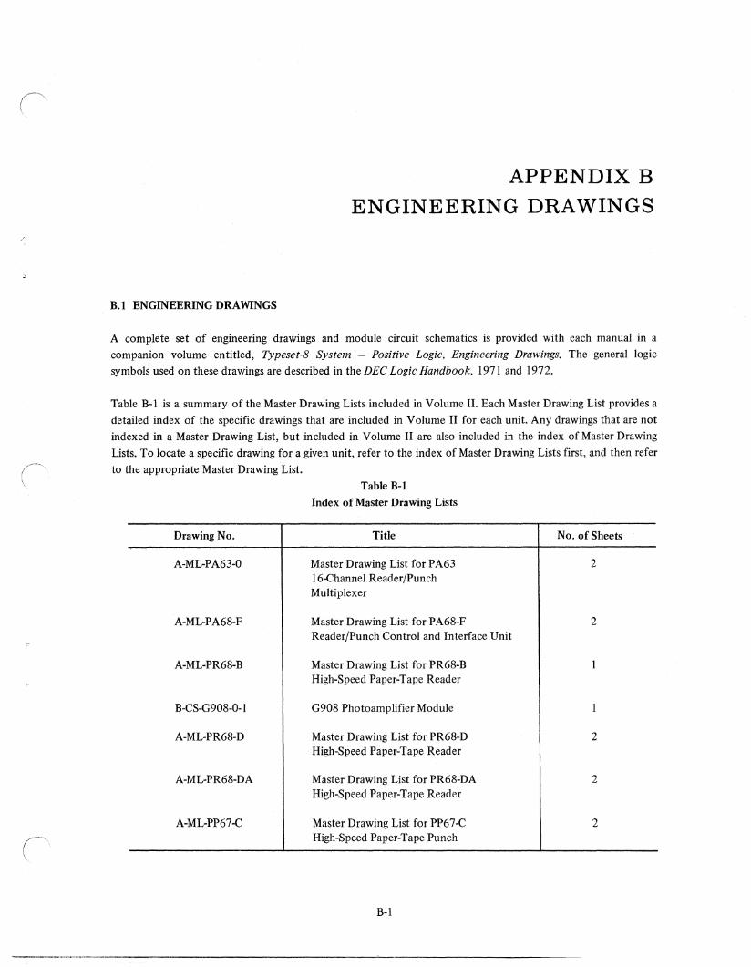
B.l ENGINEERING DRAWINGS
APPENDIX B ENGINEERING DRAWINGS
A complete set of engineering drawings and module circuit schematics is provided with each manual in a
companion volume entitled, Typeset-8 System - Positive Logic. Engineering Drawings. The general logic
symbols used on these drawings are described in the DEC Logic Handbook, 1971 and 1972.
Table B-1 is a summary of the Master Drawing Lists included in Volume II. Each Master Drawing List provides a
detailed index of the specific drawings that are included in Volume II for each unit. Any drawings that are not
indexed in a Master Drawing List, but included in Volume II are also included in the index of Master Drawing
Lists. To locate a specific drawing for a given unit, refer to the index of Master Drawing Lists first, and then refer
to the appropriate Master Drawing List.
Drawing No.
A-ML-PA63-0
A-ML-P A68-F
A-ML-PR68-B
B-CS-G908-0-1
A-ML-PR68-D
A-ML-PR68-DA
A-ML-PP67-C
Table B-1
Index of Master Drawing Lists
Title
Master Drawing List for P A63 16-Channel Reader/Punch Multiplexer
Master Drawing List for PA68-F Reader/Punch Control and Interface Unit
Master Drawing List for PR68-B High-Speed Paper-Tape Reader
G908 Photoamplifier Module
Master Drawing List for PR68-D High-Speed Paper-Tape Reader
Master Drawing List for PR68-DA High-Speed Paper-Tape Reader
Master Drawing List for PP67-C High-Speed Paper-Tape Punch
B-1
No. of Sheets
2
2
2
2
2
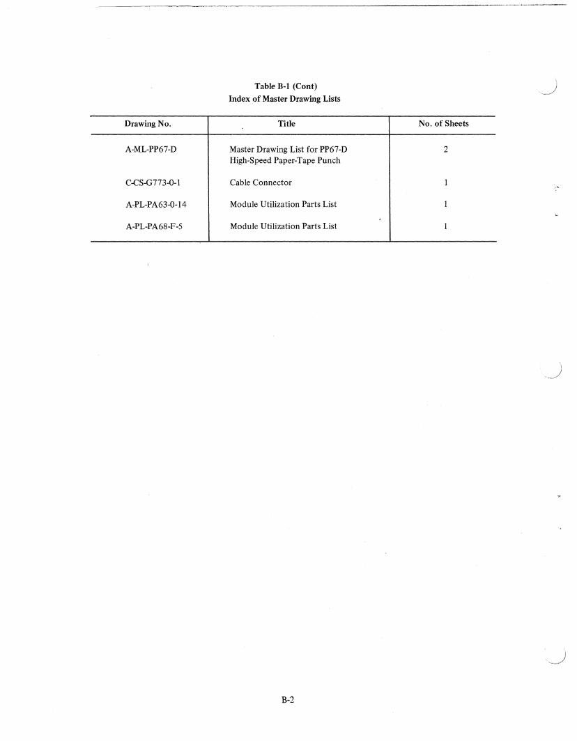
Drawing No.
A-ML-PP67-D
C-CS-G773-0-1
A-PL-PA63-0-l4
A-PL-PA68-F-5
Table B-1 (Cont)
Index of Master Drawing Lists
Title
Master Drawing List for PP67-D High-Speed Paper-Tape Punch
Cable Connector
Module Utilization Parts List
Module Utilization Parts List
B-2
No. of Sheets
2

(' :
READER'S COMMENTS TYPESET·8 SYSTEMS POSITIVE LOGIC MAINTENANCE MANUAL DEC-08-HMMPA-A·D
Your comments and suggestions will help us in our continuous effort to improve the quality and usefulness of
our publications.
What is your general reaction to this manual? In your judgment is it complete, accurate, well organized, well
written, etc.? Is it easy to use?
What features are most useful? -------------------------------------------------------------------
What faults do you find with the manual? ---------------------------------------------------------
Does this manual satisfy the need you think it was intended to satisfy? ________________ _
Does it satisfy your needs? Why?
Would you please indicate any factual errors you have found.
Please describe your position.
Name ____________________________________ __ Organization ________________ _
Street ________________ _ Department
City _________ _ State ___________ _ Zip or Country ______ ___
-----------~~-----------
- - - - - -- -- -- DoNotTear-FoldHereandStaple - - - - -- -- - -
BUSINESS REPLY MAIL NO POSTAGE STAMP NECESSARY IF MAILED IN THE UNITED STATES
Postage will be paid by:
Digital Equipment Corporation Technical Documentation Department 146 Main Street Maynard, Massachusetts 01754
FIRST CLASS PERMIT NO. 33
MAYNARD, MASS.

· /
\