Embed Size (px)
Citation preview


R K05 disk drive user's manual
EK-RK05-OP-OOl
digital equipment corporation • maynard, massachusetts
Copyright © 1976 by Digital Equipment Corporation
The material in this manual is for informational purposes and is subject to change without notice.
Digital Equipment Corporation assumes no responsibility for any errors which may appear in this manual.
Printed in U.s.A.
The following are trademarks of Digital Equipment Corporation, Maynard, Massachusetts:
DEC DECCOMM DECsystem-10 DECSYSTEM-20
DECtape DEC US DIGITAL MASSBUS
PDP RSTS TYPESET-8 TYPESET-II UNIBUS
1st Edition, November 1976
CHAPTER 1
1.1 1.2 1.3 1.4 1.5 1.5.1 1.5.2 1.5.3 1.5.4 1.5.5 1.5.6 1.5.7 1.5.S
CHAPTER 2
2.1 2.2 2.3 2.4 2.5 2.5.1 2.5.2
CHAPTER 3
3.1 3.2 3.2.1 3.2.2 3.2.3 3.2.4 3.2.5 3.2.6 3.2.7 3.2.S 3.2.9 3.2.10 3.3 3.3.1 3.3.2 3.3.3 3.3.4 3.3.5 3.3.6 3.3.7 3.3.S 3.3.9
CONTENTS
Page
GENERAL INFORMATION
INTRODUCTION .......... . . . . . . . . . . . . . . . . . . . . . .. 1-1 WARRANTY .............. . . . . . . . . . . . . . . . . . . . . . .. 1-1 SPECIFICATIONS .... . . . . . . . . . . . . . . . . . . . . . . . . . . . . . .. 1·1 50/60 Hz POWER OPTION ................................. 1-1 MAJOR ASSEMBLIES AND SYSTEMS ............. . . . . . . . . . . .. I-I
Controls and Indicators . . . . . . . . . . . . . . . . . . . . . . . . . . . . . .. 1-4 Spindle and Drive . . . . . . . . . . . . . . . . . . . . . . . . . . . . . .. 1-4 Linear Positioner .................................... 1-4 Cartridge-Handling System ........ . . . . . . . . . . . . . . . . . . . . . .. 1-4 Logic Assembly .................................... 1-4 Air System ....................................... 1-4 Power Supply . . . . . . . . . . . . . . . . . . . . . . . . . . .. 1-4 Read/Write Heads ................................... 1-4
INSTALLATION
UNPACKING AND INSPECTION .............................. 2-1 MECHANICAL INST ALLA TION AND CHECKOUT .................... 2-3 CARTRIDGE HANDLING PRACTICES AND PRECAUTIONS . . . . . . . . . . . . . .. 2-6 CARTRIDGE PACKING AND SHIPPING .......................... 2-6 NORMAL OPERATING PROCEDURES .......................... 2-7
Cartridge Loading Cartridge Unloading
INTERFACE
2-7 2-7
GENERAL ...... . . . . . . . . . . . . . . . . . . . . . . . . . . . . . . . . . . .. 3-1 INPUT INTERFACE LINES ................................. 3-1
RKII-D ......... . . . . . . . . . . . . . . . . . . . . . . . . . . .. 3-1 Select ( 4 lines) ..................................... 3-1 Cylinder Address (Slines) ............................... 3-1 Strobe ......................................... 3-1 Head Select ......... ............................ 3-3 Write Protect Set .. . . . . . . . . . . . . . . . . . . . . . . . .. 3-3 Write Data and Clock ................................. 3-3 Write Gate ....................................... 3-3 Restore (RTZ) ..................................... 3-3 Read Gate ....................................... 3-3
OUTPUT INTERFACE LINES ............................... 3-3 File Ready (Drive Ready) ............................... 3-3 Read, Write, or Seek Ready/On Cylinder ....................... 3-3 Address Accepted ................................... 3-3 Address Invalid (Logic Address Interlock) ....................... 3-3 Seek Incomplete .................................... 3-3 Write Protect Status .................................. 3-3 Write Check ...................................... 3-3 Read Data . . . . . . . . . . . . . . . . . . . . . . . . . .. 3-4 Read Clock . . . . . . . . . . . . . . . . . . . . . . . . . . . . . . . . . . . . . .. 3-4
iii
3.3.10 3.3.11 3.3.12 3.3.13 3.3.14 3.3.15
Sector Address (4 lines) Sector Pulse Index Pulse ACLow DC Low High Density/RK05 L
CONTENTS (Cont)
APPENDIX A THE RKOS-TA OFF-LINE TESTER
Figure No.
1-1 1-2 1-3 1-4 1-5 1-6 1-7 1-8 2-1 2-2 2-3 24 3-1
Table No.
I-I 1-2
ILLUSTRA TIONS
Title
Location of Major Assemblies and Systems Controls and Indicators Spindle and Drive System Linear Positioner ... . Cartridge Handling System Air System ....... . Head Loading ..... . Relationship of Disk Head, Disk, and Contaminants Shipping Bracket and Shipping Strap Location RKII Cor RKIlD Interface Cable Installation Chassis Slide Mounting ........... . RK8/E Interface Cable Installation .... . Controller/RK05 Disk Drive Interface Lines and Pin Assignments
Performance Specifications Controls and Indicators
TABLES
Title
iv
Page
34 34 34 34 34 34
Page
1-3 1-6 1-7 1-7 1-8 1-9 1-9
1-10 2-2 2-3 24 2-5 3-2
Page
1-2 1-5
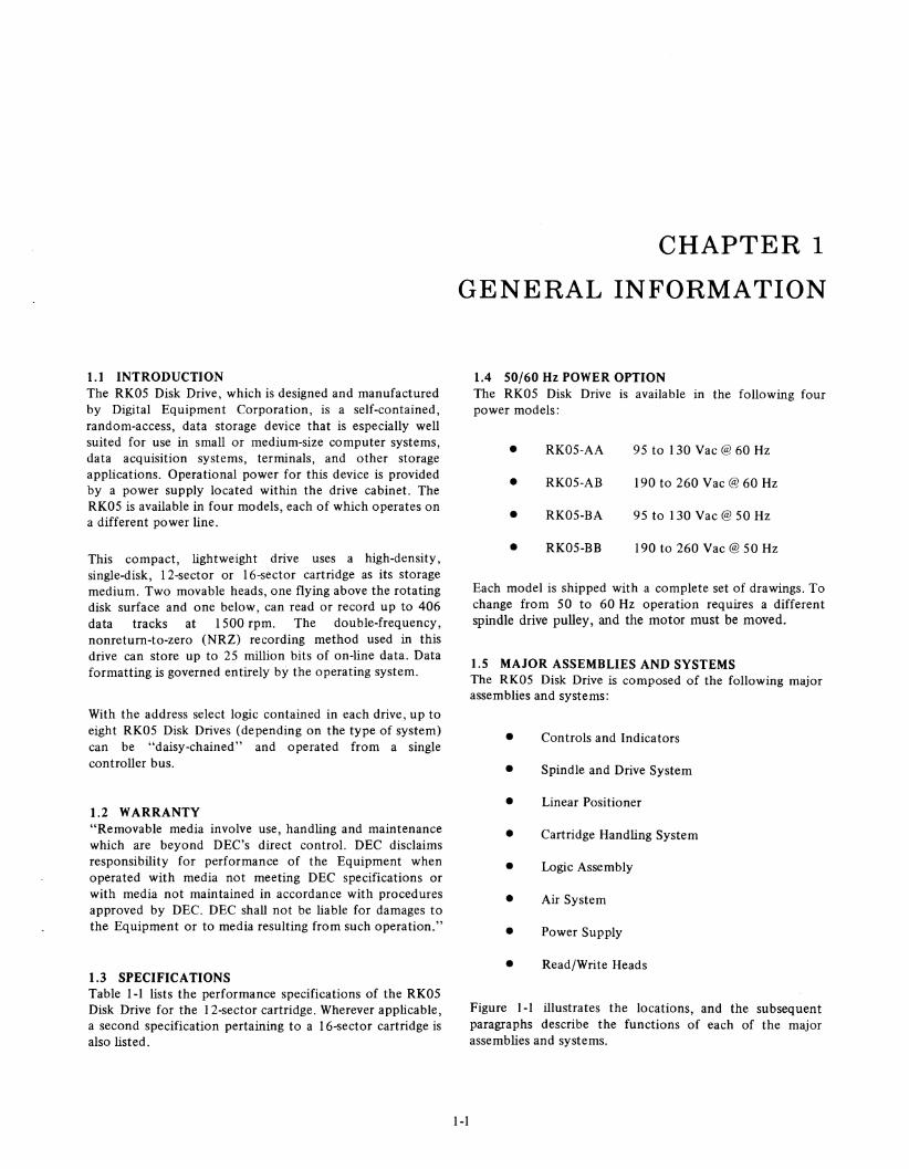
1.1 INTRODUCTION The RK05 Disk Drive, which is designed and manufactured by Digital Equipment Corporation, is a self-contained, random-access, data storage device that is especially well suited for use in small or medium-size computer systems, data acquisition systems, terminals, and other storage applications. Operational power for this device is provided by a power supply located within the drive cabinet. The RK05 is available in four models, each of which operates on a different power line.
This compact, lightweight drive uses a high-density, single-disk, 12-sector or 16-sector cartridge as its storage medium. Two movable heads, one flying above the rotating disk surface and one below, can read or record up to 406 data tracks at 1500 rpm. The double-frequency, nonreturn-to-zero (NRZ) recording method used in this drive can store up to 25 million bits of on-line data. Data formatting is governed entirely by the operating system.
With the address select logic contained in each drive, up to eight RK05 Disk Drives (depending on the type of system) can be "daisy-chained" and operated from a single controller bus.
1.2 WARRANTY "Removable media involve use, handling and maintenance which are beyond DEC's direct control. DEC disclaims responsibility for performance of the Equipment when operated with media not meeting DEC specifications or with media not maintained in accordance with procedures approved by DEC. DEC shall not be liable for damages to the Equipment or to media resulting from such operation."
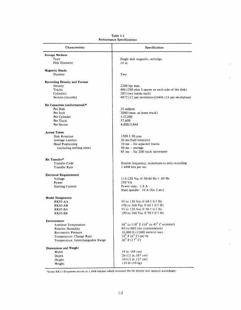
1.3 SPECIFICATIONS Table 1-1 lists the performance specifications of the RK05 Disk Drive for the 12-sector cartridge. Wherever applicable, a second specification pertaining to a 16-sector cartridge is also listed.
CHAPTER 1
GENERAL INFORMATION
1-1
1.4 50/60 Hz POWER OPTION The RK05 Disk Drive is available in the following four power models:
• RK05-AA 95 to 130 Vac@ 60 Hz
• RK05-AB 190 to 260 Vac@ 60 Hz
• RK05-BA 95 to 130 Vac@ 50 Hz
• RK05-BB 190 to 260 Vac @ 50 Hz
Each model is shipped with a complete set of drawings. To change from 50 to 60 Hz operation requires a different spindle drive pulley, and the motor must be moved.
1.5 MAJOR ASSEMBLIES AND SYSTEMS The RK05 Disk Drive is composed of the following major assemblies and systems:
• Controls and Indicators
• Spindle and Drive System
• Linear Positioner
• Cartridge Handling System
• Logic Assembly
• Air System
• Power Supply
• Read/Write Heads
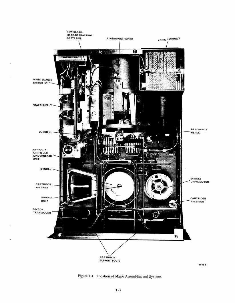
Figure 1-1 illustrates the locations, and the subsequent paragraphs describe the functions of each of the major assemblies and systems.
Characteristic
Storage Medium Type Disk Diameter
Magnetic Heads Number
Recording Density and Format Density Tracks Cylinders Sectors (records)
Bit Capacities (unformatted)* Per Disk Per Inch Per Cylinder Per Track Per Sector
Access Times Disk Rotation Average Latency Head Positioning
(including settling time)
Bit Transfer* Transfer Code Transfer Rate
Electrical Requirements Voltage Power Starting Current
Model Designation RK05-AA RK05-AB RK05-BA RK05-BB
Environment Ambient Temperature Relative Humidity Barometric Pressure
Table I-I Performance Specifications
Specification
Single disk magnetic cartridge 14 in.
Two
2200 bpi max. 406 (200 plus 3 spares on each side of the disk) 203 (two tracks each) 4872 (12 per revolution)/6496 (16 per revolution)
25 million 2040 (max. at inner track) 115,200 57,600 4,800/3,844
1500 ± 30 rpm 20 ms (half rotation) 10 ms - for adjacent tracks 50 ms - average 85 ms - for 200 track movement
Double frequency, nonreturn-to-zero recording 1.44M bits per sec
115/230 Vac @ 50/60 Hz ± .05 Hz 250 VA Power only: 1.8 A Start spindle: lOA (for 2 sec)
95 to 130 Vac @60 ± 0.5 Hz 190 to 260 Vac @ 60 ± 0.5 Hz 95 to 130 Vac@ 50 ± 0.5 Hz 190 to 260 Vac @ 50 ± 0.5 Hz
50° to 110° F (10° to 43° C nominal) 8% to 80% (no condensation) 10,000 ft (3,000 meters) max.
Temperature, Change Rate Temperature, Interchangeable Range
10° F (6° C) per hr 30° F (17° C)
Dimensions and Weight Width Depth Height Weight
19 in. (48 em) 26-1/2 in. (67 em) 10-1/2 in. (27 em) 110 Ib (50 kg)
'Some R KII-O systems record at I.S4M bits/sec which increases the bit density and capacity accordingly.
1-2
POWER SUPPLY
ABSOLUTE AIR FILLER (UNDERNEATH UNIT)
AIR DUCT
SPINDLE
CONE
SECTOR TRANSDUCER
POWER-FAIL HEAD-RETRACTING BATTERIES LINEAR POSITIONER
CARTRIDGE SUPPORT POSTS
LOGIC ASSEMBLY
Figure 1-1 Location of Major Assemblies and Systems
1-3
READ/WRITE HEADS
SPINDLE DRIVE MOTOR
CARTRIDGE RECEIVER
6858-6
1.5.1 Controls and Indicators The controls and indicators (Figure 1-2) required for normal operation are located on the front of the drive cabinet. Table 1-2 describes the function of each control or indicator.
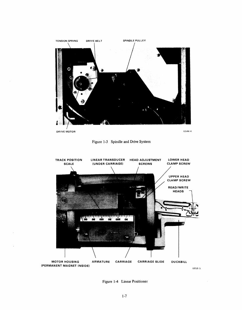
1.5.2 Spindle and Drive The spindle and drive system (Figure 1-3) is composed of the spindle, spindle drive motor, and the recording disk. A 50/60 Hz, split-phase ac motor transfers torque (via the drive belt) to the spindle drive pulley. Belt tension is maintained by a tension spring anchored to the baseplate.
The spindle speed is electronically tested by a circuit that measures the INDEX PULSE interval. When the interval increases to approximately 45 ms, indicating an unsafe speed, the drive is cycled down. If the RUN/LOAD switch is placed in the LOAD position, ac power is rerr.oved from the motor and the spindle coasts to a halt.
1.5.3 Linear Positioner The linear positioner (Figure 1-1) consists of the linear motor, the carriage, the read/write heads, and the linear positioner transducer. To move the read/write heads across the recording disk, dc current is applied to the bobbin-wound armature (Figure 1-4) of the linear motor. The resulting magnetic field reacts with a permanent magnet in the motor housing to either pull the armature into or force it out of the permanent magnetic field, depending upon the polarity of the current applied to the armature. This motion is transferred to the carriage, which is fastened to the armature. As a result, the read/write heads, which are attached to the carriage, move across the surface of the disk.
Any carriage movement is detected by the linear positioner transducer, which is located on the underside of the carriage. The transducer output is used with the control logic to determine the cylinder position of the heads, and in the servo logic to govern the speed of carriage travel.
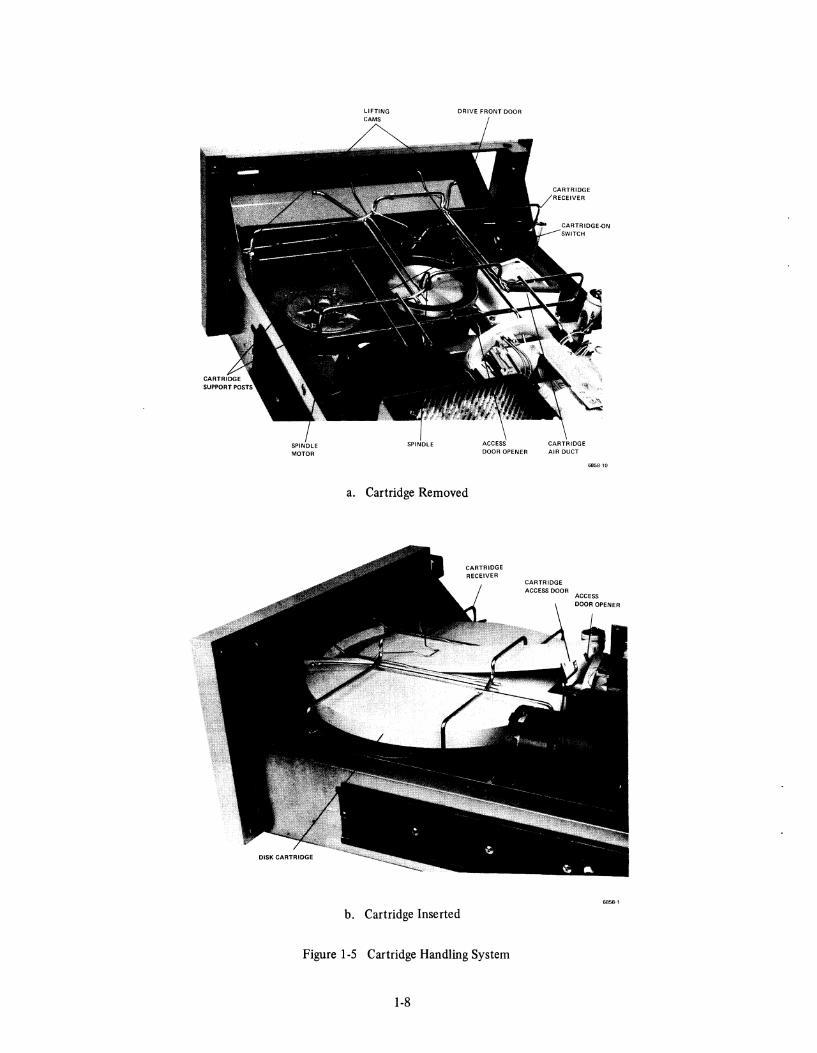
1.5.4 Cartridge-Handling System The cartridge-handling system (Figure I-Sa) consists of a cartridge receiver, two receiver lifting cams, an access door opener, a duckbill, and two cartridge support posts. During normal operation, the plastic cartridge is located only by the duckbill and support posts. The cartridge receiver merely guides the cartridge into position to be picked up by the duckbill and support posts, allowing the recording disk to rotate freely on the spindle. The rotating spindle drives the disk by magnetic coupling at the disk hub.
As the drive front door is opened, the lifting cams rotate to elevate the receiver to a slanted position and the magnetic coupling at the disk hub is released. When the disk cartridge is inserted into the receiver (Figure l-5b), the access door opener contacts the rear of the top cover, opening the access door to allow entry of the read/write heads.
1-4
As the drive front door is closed, the cartridge is lowered to the operating position, and the magnetic coupling again engages the disk hub. When the cartridge is in the operating position, the plastic case depresses the cartridge-on switch and removes the no-cartridge interlock condition. The cartridge receiver should not hold the cartridge tightly.
1.5.5 Logic Assembly The logic assembly (Figure 1-1), located in the right rear portion of the disk drive, holds eight printed circuit cards. Three of these cards contain the system logic and the read/write circuits. Two cards contain the positioner servo logic. One card is the cable connector that interfaces the electronics with the positioner and other chassis-mounted components, while the remaining two cards contain the interface cables and terminators.
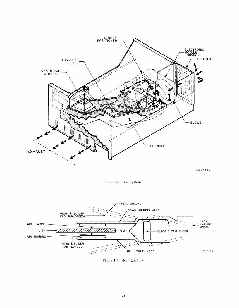
1.5.6 Air System The air system (Figure 1-6) consists of the prefilter, blower, absolute filter, plenum chamber, and the cartridge air duct. As the blower rotates, unfiltered air is drawn through the prefilter, where it is purged of large dust particles. The prefiltered air is then circulated through the logic assembly and into the plenum. From there, the air passes through the absolute filter (where minute contamination is removed), up the cartridge air duct, and into the disk cartridge. Cooling air from the absolute filter is also shunted, by the plenum, through the linear positioner. Exhaust air exits through the front grill of the drive.
1.5.7 Power Supply The power supply (Figure I-I), located in the left rear portion of the disk drive, furnishes all the dc voltages for the drive. The power supply can operate with a 115 V or 230V, 50 or 60 Hz line voltage input.
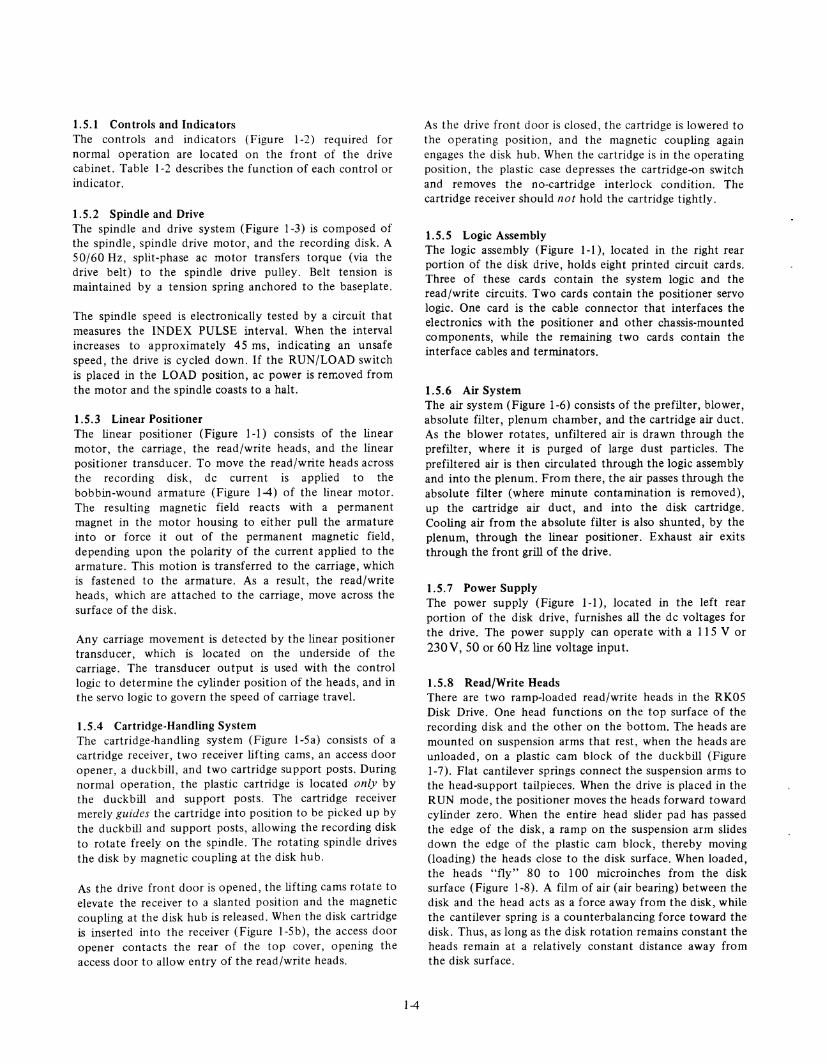
1.5.8 Read/Write Heads There are two ramp-loaded read/write heads in the RK05 Disk Drive. One head functions on the top surface of the recording disk and the other on the bottom. The heads are mounted on suspension arms that rest, when the heads are unloaded, on a plastic cam block of the duckbill (Figure 1-7). Flat cantilever springs connect the suspension arms to the head-support tailpieces. When the drive is placed in the RUN mode, the positioner moves the heads forward toward cylinder zero. When the entire head slider pad has passed the edge of the disk, a ramp on the suspension arm slides down the edge of the plastic cam block, thereby moving (loading) the heads close to the disk surface. When loaded, the heads "fly" 80 to 100 microinches from the disk surface (Figure 1-8). A film of air (air bearing) between the disk and the head acts as a force away from the disk, while the cantilever spring is a counterbalancing force toward the disk. Thus, as long as the disk rotation remains constant the heads remain at a relatively constant distance away from the disk surface.
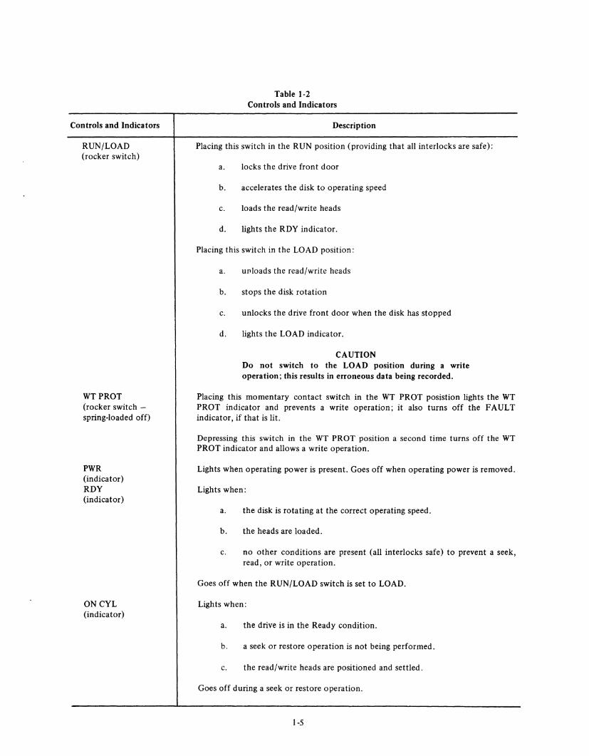
Controls and Indicators
RUN/LOAD (rocker switch)
WTPROT (rocker switch -spring-loaded off)
PWR (indicator) RDY (indicator)
ONCYL (indicator)
Table 1-2 Controls and Indicators
Description
Placing this switch in the RUN position (providing that all interlocks are safe):
a. locks the drive front door
b. accelerates the disk to operating speed
c. loads the read/write heads
d. lights the RDY indicator.
Placing this switch in the LOAD position:
a. unloads the read/write heads
b. stops the disk rotation
c. unlocks the drive front door when the disk has stopped
d. lights the LOAD indicator.
CAUTION Do not switch to the LOAD position during a write operation; this results in erroneous data being recorded.
Placing this momentary contact switch in the WT PROT posistion lights the WT PROT indicator and prevents a write operation; it also turns off the FAULT indicator, if that is lit.
Depressing this switch in the WT PROT position a second time turns off the WT PROT indicator and allows a write operation.
Lights when operating power is present. Goes off when operating power is removed.
Lights when:
a. the disk is rotating at the correct operating speed.
b. the heads are loaded.
c. no other conditions are present (all interlocks safe) to prevent a seek, read, or write operation.
Goes off when the RUN/LOAD switch is set to LOAD.
Lights when:
a. the drive is in the Ready condition.
b. a seek or restore operation is not being performed.
c. the read/write heads are positioned and settled.
Goes off during a seek or restore operation.
1-5
Controls and Indicators
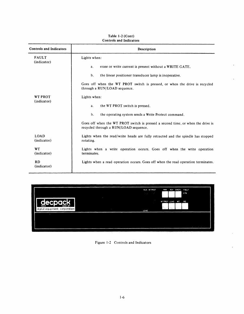
FAULT (indicator)
WTPROT (indicator)
LOAD (indicator)
WT (indicator)
RD (indicator)
g,ecpa£~, .. . -. . .... .
Lights when:
Table 1·2 (Cont) Controls and Indicators
Description
a. erase or write current is present without a WRITE GATE.
b. the linear positioner transducer lamp is inoperative.
Goes off when the WT PROT switch is pressed, or when the drive is recycled through a RUN/LOAD sequence.
Lights when:
a. the WT PROT switch is pressed.
b. the operating system sends a Write Protect command.
Goes off when the WT PROT switch is pressed a second time, or when the drive is recycled through a RUN/LOAD sequence.
Lights when the read/write heads are fully retracted and the spindle has stopped rotating.
Lights when a write operation occurs. Goes off when the write operation terminates.
Lights when a read operation occurs. Goes off when the read operation terminates.
RUN wrPROT ewe RDY ONCYl rAULT
111111 .....
'';,"T PROT LOAD WT RO
11111111 LOAD
Figure 1·2 Controls and Indicators
1·6
TENSION SPRING DRIVE BELT SPINDLE PULLEY
DRIVE MOTOR
TRACK POSITION SCALE
65444
Figure 1-3 Spindle and Drive System
LINEAR TRANSDUCER HEAD ADJUSTMENT LOWER HEAD (UNDER CARRIAGE) SCREWS CLAMP SCREW
UPPER HEAD CLAMP SCREW
MOTOR HOUSING ARMATURE CARRIAGE CARRIAGE SLIDE DUCKBILL (PERMANENT MAGNET INSIDE)
Figure 1-4 Linear Positioner
1-7
6858-5
MOTOR
a. Cartridge Removed
b. Cartridge Inserted
Figure 1-5 Cartridge Handling System
1-8
CARTRIDGE ACCESS DOOR
6858-10
6858-1
CARTRIDGE AIR DUCT
EXHAUST
Figure 1-6 Air System
HEAD a SLIDER _____ Ii' -
PREFILTER
CP-0272
r- HEAD BRACKET
<::::::.:.--=--:.t------0-DOWN (UPPER) HEAD
PAD (UNLOADED) • -----:.'- ----------..,.;--_ /--::: ___ '-I "/ '"- ' c'\ __ lJ - HEAD
AIR BEARING - I t i G L, ~-:!!:~==~St__LOADING . < l: SPRING DISK - m$//0iM@'~ RAMPS 4--'-- PLASTIC CAM BLOCK
•
CP-0254
Figure 1-7 Head Loading
1-9
08-0884
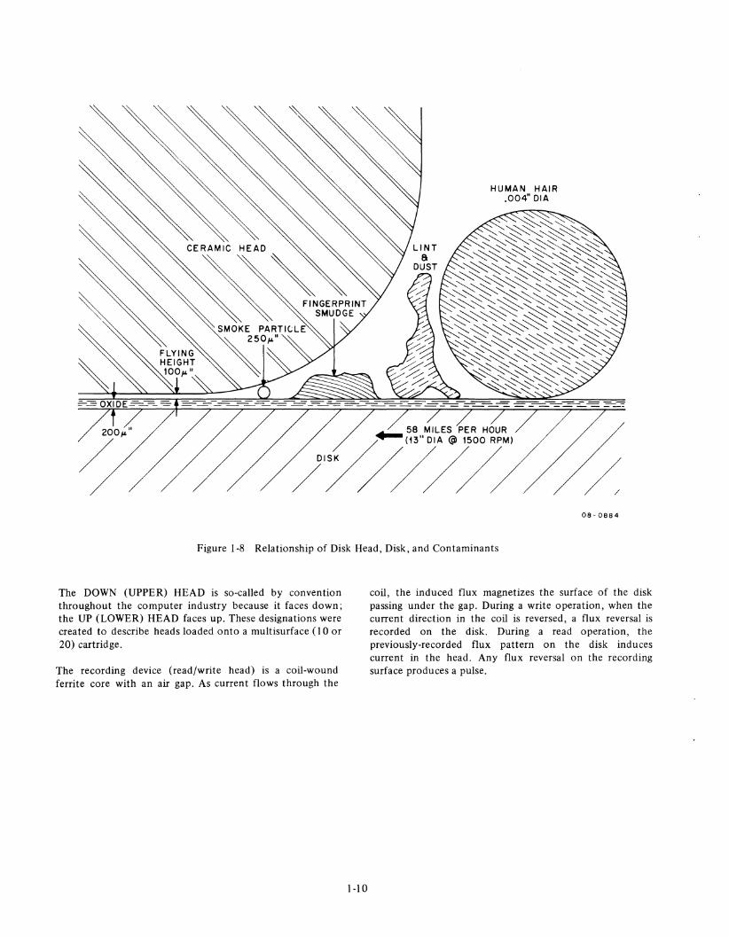
Figure 1-8 Relationship of Disk Head, Disk, and Contaminants
The DOWN (UPPER) HEAD is so-called by convention throughout the computer industry because it faces down; the UP (LOWER) HEAD faces up. These designations were created to describe heads loaded onto a multisurface (10 or 20) cartridge.
The recording device (read/write head) is a coil-wound ferrite core with an air gap. As current flows through the
1-10
coil, the induced flux magnetizes the surface of the disk passing under the gap. During a write operation, when the current direction in the coil is reversed, a flux reversal is recorded on the disk. During a read operation, the previously-recorded flux pattern on the disk induces current in the head. Any flux reversal on the recording surface produces a pulse.
2.1 UNPACKING AND INSPECTION The RK05 Disk Drive can be shipped in a rack as an integral part of a system or in a separate container. If the drive is shipped in a rack, the rack should be positioned in the final installation location and unpacked as follows:
I. Remove the shipping brackets from the drive by removing the snap-on bezel beneath the lowest drive.
2. Remove the screws attaching the shipping bracket and latch molding to both sides of the drive.
3.
4.
5.
6.
CAUTION Do not use the drive front door handle to pull the drive out from the rack.
Slide the drive out about 3 inches from the rack and pull the shipping brackets out from the sides of the drive. Attach the latch molding back onto the drive with the shipping bracket screws.
Slide the lowest drive out far enough to gain access to the shipping brackets on the drive directly above it and remove the screws from these two shipping brackets.
Repeat Steps 3 and 4 for each drive in the rack.
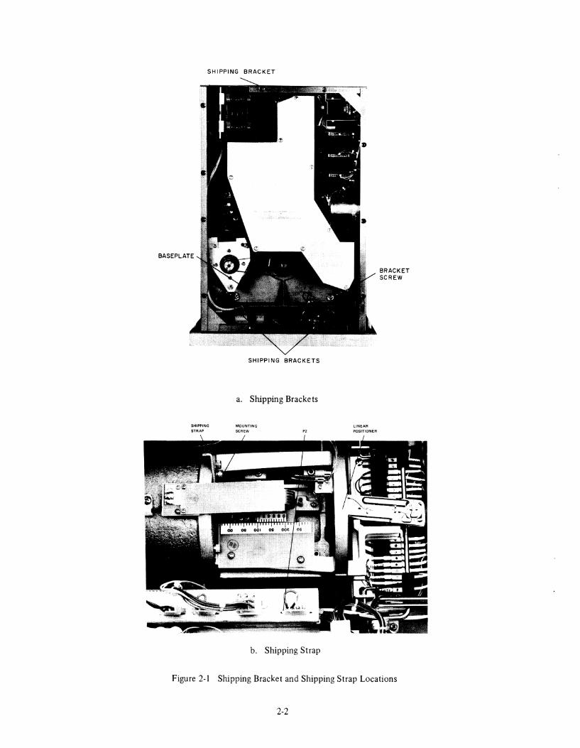
Remove the drive bottom cover and remove the screws that attach the three internal shipping brackets to the baseplate (Figure 2-la).
CAUTION Do not operate drive with shipping brackets attached.
2-1
7.
8.
9.
10.
CHAPTER 2
INSTALLATION
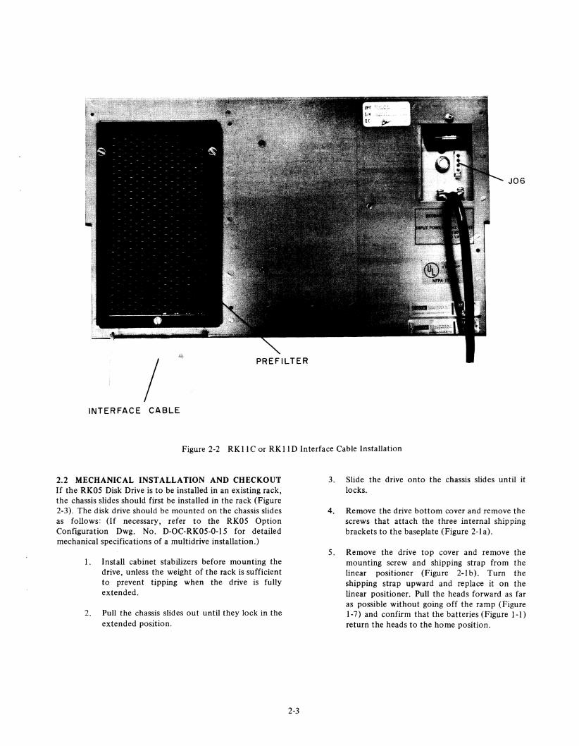
If RK05 drives are "daisy-chained" with RK03 drives in a multidrive installation, arrange the RK05s consecutively at the controller end of the bus to avoid interruption of the AC LOW and DC LOW interface lines, which are not carried by the RK03s. If this arrangement is not possible, all RK05s that are separated on the bus by RK03s must be connected by separate cables between their 106 connections (Figure 2-2).
Remove the drive top cover and remove the mounting screw and shipping strap from the linear positioner (Figure 2-1 b). Turn the shipping strap upward and replace it on the linear positioner, making sure it is tightly secured.
Retain all packing material for possible reshipment. Inspect the drive for possible damage. Report any damage to the carrier and to Digital Equipment Corporation.
In the case of RK05 Disk Drive relocation or reshipment, replace the shipping brackets and shipping strap in the shipping position; repeat this unpacking and inspection procedure when the drive is reinstalled.
If the drive is shipped in a separate container, use care while unpacking it. Do not drop the drive or subject it to unreasonable impact.
SHIPPING BRACKET
SHIPPING STRAP
SHIPPING BRACKETS
a. Shipping Brackets
MOUNTING SCREW '2
b. Shipping Strap
LINEAR POSITIONER
BRACKET SCREW
Figure 2-1 Shipping Bracket and Shipping Strap Locations
2-2
JOG
INTERFACE CABLE
Figure 2-2 RK II C or RK II D Interface Cable Installation
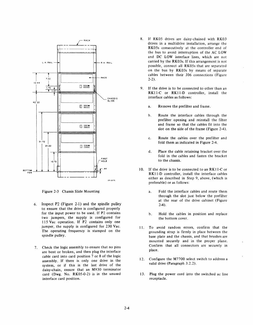
2.2 MECHANICAL INSTALLATION AND CHECKOUT If the RKOS Disk Drive is to be installed in an existing rack, the chassis slides should first be installed in the rack (Figure 2-3). The disk drive should be mounted on the chassis slides as follows: (If necessary, refer to the RKOS Option Configuration Dwg. No. D-OC-RKOS-O-IS for detailed mechanical specifications of a multidrive installation.)
I. Install cabinet stabilizers before mounting the drive, unless the weight of the rack is sufficient to prevent tipping when the drive is fully extended.
2. Pull the chassis slides out until they lock in the extended position.
2-3
3. Slide the drive onto the chassis slides until it locks.
4. Remove the drive bottom cover and remove the screws that attach the three internal shipping brackets to the baseplate (Figure 2-1 a).
S. Remove the drive top cover and remove the mounting screw and shipping strap from the linear positioner (Figure 2-1 b). Turn the shipping strap upward and replace it on the linear positioner. Pull the heads forward as far as possible without going off the ramp (Figure 1-7) and confirm that the batteries (Figure I-I) return the heads to the home position.
BOTTOM PAN
;---,-;---
l.H. RAll-i-'
r f
il 7.22
10,44 ~ ~-: 1.47 .'
T :1
42.22
:1
rRACt<
----; -+,
4-R.H.
: +-j -RK05
[] ccc. aoco
,.! :41
r i~ [] CCC. Dooa
I: rn 000.
0000
RAIL
CHASSIS SLI DE
317T :1 I:
6.
7.
21.22 [] ccc. 0000
T I I
10.72
1 ,
- -l.- __ ---
. :
, 11
Ir FIRS HOl T E
£.44
•
Figure 2-3 Chassis Slide Mounting
CP-OZ73
Inspect P2 (Figure 2-1) and the spindle pulley to ensure that the drive is configured properly for the input power to be used. If P2 contains two jumpers, the supply is configured for 115 Vac operation. If P2 contains only one jumper, the supply is configured for 230 Vac. The operating frequency is stamped on the spindle pulley.
Check the logic assembly to ensure that no pins are bent or broken, and then plug the interface cable card into card position 7 or 8 of the logic assembly. If there is only one drive in the system, or if this is the last drive of the daisy-chain, ensure that an M930 terminator card (Dwg. No. RKOS-O-2) is in the unused interface card position.
2-4
8. If RKOS drives are daisy-chained with RK03 drives in a multidrive installation, arrange the RKOSs consecutively at the controller end of the bus to avoid interruption of the AC LOW and DC LOW interface lines, which are not carried by the RK03s. If this arrangement is not possible, connect all RKOSs that are separated on the bus by RK03s by means of separate cables between their J06 connections (Figure 2-2).
9. If the drive is to be connected to other than an RK Il-C or RK Il-D controller, install the interface cables as follows:
10.
11.
12.
13.
a.
b.
c.
d.
Remove the prefilter and frame.
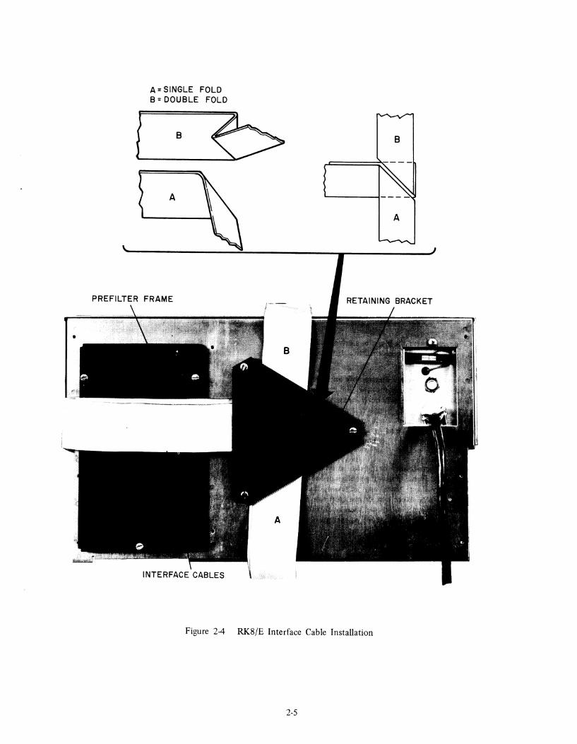
Route the interface cables through the prefilter opening and reinstall the filter and frame so that the cables fit into the slot on the side of the frame (Figure 2-4).
Route the cables over the prefilter and fold them as indicated in Figure 2-4.
Place the cable retaining bracket over the fold in the cables and fasten the bracket to the chassis.
If the drive is to be connected to an RK ll-C or RKII-D controller, install the interface cables either as described in Step 9, above, (which is preferable) or as follows:
a. Fold the interface cables and route them through the slot just below the prefilter at the rear of the drive cabinet (Figure 2-4).
b. Hold the cables in position and replace the bottom cover.
To avoid random errors, confirm that the grounding strap is firmly in place between the base plate and the chassis, and that brushes are mounted securely and in the proper plane. Confirm that all connectors are securely in place.
Configure the M7700 select switch to address a valid drive (Paragraph 3.2.2).
Plug the power cord into the switched ac line receptacle.
A = SINGLE FOLD B = DOUBLE FOLD
Figure 2-4 RK8/E Interface Cable Installation
2-5
A
14. Turn the processor keyswitch ON to apply power to the drive.
15. Check that the spindle is clean, and that the heads are not bent or dirty.
2.3 CARTRIDGE HANDLING PRACTICES AND PRECAUTIONS To obtain maximum performance and high reliability from the RK05 Disk Drive, the following precautions and cartridge-handling practices must be observed:
1. Store cartridges in a clean, dry area away from direct sunlight. Do not expose cartridges to heat. They may be stored on edge or stacked; however, stacks of more than 3 or 4 cartridges should be avoided. Do not place heavy items on the plastic cartridge cases. Do not store cartridges on top of computer cabinets or in places where dirt can be blown by fans into cartridge interiors.
2. Whenever a cartridge is not in a drive, enclose it in a plastic bag to exclude dust or dirt.
3. Professional cartridge disassembly and cleaning is required every six months; however, disks should be cleaned whenever they are excessively dirty, or when a high transient error rate is encountered. In such instances, a diskcleaning service, listed by Digital Equipment Corporation, should be contacted at once.
4. Place stiff cardboard or plastic labels only in the molded frame at the front edge of the disk cartridge without using any adhesives. Labels placed on any other part of the cartridge may interfere with the drive operation or introduce contamination into the drive or the interior of the cartridge.
5. Allow the temperature of the cartridge to become stabilized with the room temperature before using the cartridge. If cartridges are exposed to outside temperature extremes, or if the temperature differential between drive and cartridge exceeds 20° F, a two-hour stabilization period is necessary.
2-6
6.
7.
8.
Although cartridges recorded on RK03s and RK05s are fully interchangeable, allow them to stabilize before new data is recorded on them. Data interchangeability between drives is only guaranteed if the temperature difference does not exceed 30° F (17° C), even though a specific drive/cartridge combination may operate over a temperature range of 50° to 110° F (l00 to 43° C).
Keep the spindle hub clean and free from nicks and burrs to ensure reliable cartridge operation. Because the hub is slightly magnetic, do not expose it to metal chips that could adhere to the mounting surface. Periodically inspect the coupling hub on the bottom of the disk cartridge for dirt, metal chips, plastic chips in cone, etc.
A sustained tinging, scratching, or rumbling sound (not to be confused with spindle ground brushes) that is the result of head-to-disk contact may occur if the cartridge is not properly seated on the spindle, if excessive contamination has built up in the interior of the cartridge, or if the cartridge or the drive is defective. If this sound is heard, shut down the drive immediately to avoid damage to the read/write heads. Remove the disk cartridge and examine the heads for damage or excessive dirt. If necessary, clean or replace the heads. Do not reuse the cartridge without first checking it for surface damage.
CAUTION NEVER CYCLE A BAD CARTRIDGE THROUGH AN INSTALLATION OF SEVERAL DRIVES. This practice can ruin all the read/write heads or contaminate all drives in a multidrive installation, which will, in turn, damage all other cartridges run in these drives.
9. Always keep the front door of the drive closed and keep all covers on to prevent unnecessary entry of atmospheric dirt or dust.
2.4 CARTRIDGE PACKING AND SHIPPING Data recorded on disk cartridges may be degraded by exposure to any sort of small magnet brought into intimate contact with the disk surface. If cartridges are to be shipped in the cargo hold of an aircraft, precautions are necessary against possible exposure to magnetic sources. Because physical separation from the magnetic source is the best
protection against accidental erasure of a cartridge, cartridges should be packed at least three inches within the box. This amount of separation should be adequate to protect against any magnetic sources likely to be encountered during transportation, making it generally unnecessary to ship cartridges in specially shielded boxes.
2.5 NORMAL OPERATING PROCEDURES All drives in a multidrive system must have operating power applied even when the drive is not in use. In addition, unused drives should be left write-enabled, and with the RUN/LOAD switch in the LOAD position.
IMPORT ANT: ON EARLIER MODEL RKOS DISK DRIVES EQUIPPED WITH A POWER ON/OFF SWITCH, DO NOT USE THE ON/OFF SWITCH DURING SYSTEM OPERA TION TO REMOVE OPERATING POWER FROM AN INDIVIDUAL DRIVE.
Because the DC LOW interface signal is common to all drives in a multidrive system, a power loss in anyone drive disables all the drives in the system. If the drive power is controlled by a processor keyswitch, all drive ON/OFF switches should be left ON; however, all RUN/LOAD switches should be set to LOAD before system power is removed.
2.5.1 Cartridge Loading The procedure for cartridge loading is as follows:
I. Set the RUN LOAD switch on all drives to LOAD and observe that the LOAD indicator lights.
2-7
2.
3.
CAUTION If the LOAD indicator is not lit, the drive front door is locked. In this case, do not attempt to force the front door open.
Open the front door of the drive and gently insert a clean, operable disk cartridge fully into the cartridge receiver. DO NOT TWIST OR FORCE THE CARTRIDGE DURING INSERTION!
Close the front door of the drive and set the RUN/LOAD switch to RUN.
4. Wait for the RDY and ON CYL indicators to light, the drive is now ready to perform seek, read, or write operations.
2.5.2 Cartridge Unloading The procedure for cartridge unloading is as follows:
I. Set the RUN/LOAD switch to LOAD and observe that the RDY indicator goes out. After approximately 30 seconds, the LOAD indicator will light.
2.
3.
4.
Open the drive front door and gently withdraw the disk cartridge.
If another cartridge is not loaded, close the drive front door to prevent unnecessary entry of atmospheric dirt or dust.
Store the cartridge in a clean plastic bag.

3.1 GENERAL The flexibility achieved with the address select logic and the eight-position address select switch permits the RK05 Disk Drive to be connected to a variety of computer systems. In the RKII-C and RK8/E systems, up to four drives can be serially connected to a single bus; in the RKll-D system, up to eight drives can be serially connected.
Interface cable connection of the RK05 Disk Drive is made to card position 7 or 8 of the electronic module. These card positions are parallel-wired so that several drives may be daisy-chained in a multi drive configuration; that is, card position 7 or 8 of the first drive is connected to card position 7 or 8 of the succeeding drive, etc. (By convention, card position 7 is used for input signals; card position 8 is used for output signals.) If there is only one drive in the system, an M930 terminator card must be installed in the unused interface card position; if there is more than one drive in the system, only the last drive on the bus must have the M930 terminator card in the unused interface card position. The interface signal levels are determined by the M930 terminator card. An assertion, or logic I, is approximately +0.5 Vdc, and a negation, or logic 0, is approximately +3.5 Vdc.
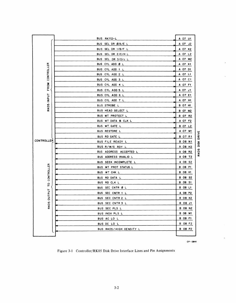
Figure 3-1 illustrates and the following paragraphs describe the function of each interface line. The signals listed, being bus signals, operate according to negative logic; they are asserted low. Appendix A contains a glossary of RK05 backplane connections.
3.2 INPUT INTERFACE LINES
3.2.1 RKII-D This line (BUS RKII-D L) transmits a signal that configures the address select logic to operate with a particular controller type. A logical 0 on this line indicates that the controller is not an RKlI-D (thus, the controller is either an RKII-C or an RK8/E, both of which control only four drives on a single bus), while a logical I indicates that the controller is an RKII-D.
3-1
CHAPTER 3
INTERFACE
3.2.2 Select (4 lines) BUS SEL DR 0/ A/E, I/B/F, 2/C/H, and 3/D/J L operate in conjunction with the RK II-D interface line and an eight-position address select switch on the M7700 card to determine the drive address assignment and selection by one of the following two methods:
a.
b.
With a logical 0 on the RKII-D line, the M7700 selection circuit is configured to decode the four selection lines as a linear set. In a particular drive, only one of the four lines is internally connected (via positions 0 through 3 of the address select switch) to the drive control logic. To select a drive, the controller places a logical I on the desired select line. This line remains at logical I throughout the entire data transfer or control operation.
With a logical 1 on the RK II-D line, the M7700 selection is configured to decode the four selection lines as a binary-encoded set. To select a drive, the controller places a 3-bit binary code, which corresponds to the drive address, on these select lines. This binary code is then translated by a three-line-to-eight-line decoder to activate only one of the eight address select switch positions.
3.2.3 Cylinder Address (8 lines) BUS CYL ADD 0 L through BUS CYL ADD 7 L determine the cylinder position of the read/write heads. In order to move the heads to a desired cylinder, the controller places a corresponding 8-bit binary code on the lines (valid codes=O through 202, 0). These lines are gated by the Strobe signal to position the heads at the selected cylinder. The binary code remains on the lines until either the Address Acknowledged or the Address Invalid signal is returned from the drive (Paragraph 3.3.3).
3.2.4 Strobe BUS STROBE L transmits a signal that gates the Cylinder Address or Restore line. The controller places a logical I on the Strobe line, only after the Cylinder Address or the Restore signals are fully settled on their respective lines.
BUS RKllD-L
BUS SEL DR 0/A/E L
BUS SEL DR l/B/F L
BUS SEL DR 2/C/H L
BUS SEL DR 3/D/J L a:: BUS CYL ADD III L w ..J ..J BUS CYL ADD 1 L 0 a:: BUS CYL ADD 2 L I-z 0 BUS CYL ADD 3 L u
~ BUS CYL ADD 4 L 0 a:: ~ BUS CYL ADD 5 L I- BUS CYL ADD 6 L :::> n. z BUS CYL ADD 7 L -on BUS STROBE L 0 :00: a:: BUS HEAD SELECT L
BUS WT PROTECT L
BUS WT DATA a CLK L
BUS WT GATE L
BUS RESTORE L
BUS RD GATE L CONTROLLER BUS FILE READY L
BUS R/W/S RDY L
BUS ADDRESS ACCEPTED L
BUS ADDRESS INVALID L
BUS SEEK INCOMPLETE L a:: w BUS WT PROT STATUS L ..J ..J 0 BUS WT CHK L a:: I-z BUS RD DATA L 0 u 0 BUS RD CLK L I-
CNTR III BUS SEC L I-:::> BUS SEC CNTR 1 L n. I-:::> BUS SEC CNTR 2 L 0 on BUS SEC CNTR 3 L 0 :00: a:: BUS SEC PLS L
BUS INDX PLS L
BUS AC LO L
BUS DC LO L
BUS RK05/HIGH DENSITY L
Figure 3-1 Controller/RK05 Disk Drive Interface Lines and Pin Assignments
3-2
A 07
A 07
A 07
A 07
A 07
A 07
A 07
A 07
A 07
A 07
A 07
A 07
A 07
B 07
B 07
B 07
A 07
B 07
A 07
B 07
B 08
A 08
A 08
A 08
A 08
B 08
B 08
B 08
B 08
B 08
A 08
B 08
B 08
B 08
B 08
B 08
B 08
B 08
Ul
J2
K2
L2
M2
Kl
01
Ll
Cl
Fl
Jl
El
H1
HI
M2
R2
F2
L2
Ml
Rl
Nl
H2
R2
T2
S2
PI
Kl
S2
SI
L1
P2
K2
Jl
N2
Ml
Fl
F2
P2
CP - 0841
w > ii: Q
:00: If)
o on o :00: a::
The Strobe line remains at logical 1 until either the Address Acknowledged or the Address Invalid signal is returned from the drive.
3.2.5 Head Select BUS SEL UPPER HD L transmits a signal that determines which of the two read/write heads is to be selected. The controller places a logical 1 on this line to select the upper head, and a logical 0 to select the lower head. Either signal remains on the line throughout the entire read or write operation.
3.2.6 Write Protect Set BUS WT PROTECT L transmits a signal that disables the drive write amplifiers to prevent a write operation. The controller places a logical 1 on this line to set the Write Protect flip-flop and inhibit the write capability of the drive. The Write Protect flip-flop is also set if the WT PROT indicator is off and the operator presses the WT PROT switch (Paragraph 1.4.1).
3.2.7 Write Data and Clock BUS WT DATA & CLK L transmits multiplexed data and clock pulses to the disk drive.
3.2.8 Write Gate BUS WT GATE L transmits a signal to simultaneously turn on both the write and erase current in the selected write head. The controller places a logical 1 on this line 1 /1s prior to transmitting the write data. This line remains at logical 1 throughout the data transmission time.
3.2.9 Restore (RTZ) BUS RESTORE L transmits a signal to position the read/write heads at cylinder zero. The controller places a logical 1 on this line prior to issuing the Strobe (BUS STROBE L) signal. About 2 /1s after this signal is issued, the drive returns an Address Acknowledged signal, clears the address register, and moves the heads to cylinder zero. The Restore line remains at logical 1 until the Address Acknowledged signal is received by the controller.
3.2.10 Read Gate BUS RD GATE L transmits a signal that allows data to be read from the drive. The controller places a logical 1 on this line to enable the Read Clock and Read Data output lines. This line remains at logical 1 throughout the entire read operation.
3.3 OUTPUT INTERF ACE LINES
3.3.1 File Ready (Drive Ready) BUS FILE RDY L transmits a logical 1 to indicate the following conditions:
a. Drive operating power is correct.
b. A disk cartridge is properly loaded.
3-3
c. The drive front door is closed.
d. RUN/LOAD switch is in the RUN position.
e. Spindle i~ rotating at the correct speed.
f. Read/write heads are loaded.
g. Write Check is false.
3.3.2 Read, Write, or Seek Ready/On Cylinder BUS R/W /S RDY L transmits a logical 1 to indicate that the drive is in the File Ready condition (Paragraph 3.3.1) and is not performing a seek operation.
3.3.3 Address Accepted BUS ADDRESS ACCEPTED L transmits a 5-/1s negative pulse to indicate that the drive has accepted a Seek command with a valid address and the command execution has begun. The negative pulse is generated about 2 /1S after receipt of the Strobe signal, even if there is no change from the present address.
3.3.4 Address Invalid (Logic Address Interlock) BUS LOG ADD INT L transmits a 5-/1s negative pulse to indicate that the drive has received a nonexecutable Seek command with a cylinder address greater than 202. For this case, the Seek command is suppressed in the drive and the heads are not moved. The pulse generation time is the same as for the Address Acknowledged signal.
3.3.5 Seek Incomplete BUS SIN L transmits a logical 1 to indicate that some malfunction in the drive did not allow the seek operation to be completed. This line remains low until a Restore command is received or the operator sets the RUN/LOAD switch to LOAD and then back to RUN.
3.3.6 Write Protect Status BUS WT PROT STATUS L transmits a logical 1 to indicate that the write capability of the drive is inhibited (write protected). When this line is at logical 1, the WT PROT indicator on the drive control panel lights (Paragraph 1.4.1).
3.3.7 Write Check BUS WT CHK L transmits a logical 1 to indicate the following conditions:
a. Erase or write current without a WRITE GATE.
b. Inoperative linear positioner transducer lamp.
When the Write Check signal is at a logical 1, all external commands to the drive are suppressed and the FAULT indicator on the drive control panel lights. If the fault condition is temporary, the operator may turn off the FA UL T indicator by pressing the WT PROT switch. This
action, however, causes the WT PROT indicator to light; the WT PROT switch must be pressed a second time to turn off the WT PROT indicator (Paragraph 1.4.1).
3.3.8 Read Data BUS RD DATA transmits read data only (160-ns pulses).
3.3.9 Read Clock BUS RD CLK L transmits read clock pulses only (160-ns pulses).
3.3.10 Sector Address (4 lines) BUS SEC CNTR 0 through 3 L indicate which sector is passing under the read/write heads. The sector address is a 4-bit binary code derived from the Sector Address counter.
3.3.11 Sector Pulse BUS SEC PLS L transmits a 2-J.ls negative pulse each time a sector slot passes the sector transducer. The index slot (unique slot) is suppressed in this line and is transmitted on a separate Index Pulse line.
3.3.12 Index Pulse BUS INDX PLS L transmits a single 2-J.ls negative pulse for each revolution of the disk. The Index Pulse occurs 600 J.ls
3-4
after the last sector pulse and is generated each time the index slot (unique slot) is detected by the sector transducer.
3.3.13 AC Low BUS AC LO L transmits a logical 1 when there is a loss (for more than 45 ms) of the 30 Vac within the drive. When AC Low occurs, the drive finishes reading/writing the current sector, then initiates a normal head-retract and unload cycle. If a total power loss occurs before the heads are completely retracted, the safety relay is de-energized to retract the heads under battery power (emergency retract).
3.3.14 DC Low BUS DC LO L transmits a logical 1 when the ±IS Vdc within the drive drops to 12 Vdc or below. When DC Low is generated, the safety relay is de-energized to retract the heads under battery power (emergency retract). Since the RUN gate of each drive is connected to the DC Low bus, a DC Low signal from anyone drive in a multidrive system disables all the drives in the system.
3.3.15 High Density /RKOS L BUS RKOS L transmits a logical 1 (indicating high density only) whenever the drive is selected. (All RKOSs are high density.)

APPENDIX A
THE RK05-TA OFF-LINE TESTER
A.l MOVE FUNCTIONS
I. STEP - incrementing cylinder seek to limit and a high speed return.
2. ALT (Alternate) - an incrementing seek from the cylinder address selected.
3. OSC - oscillate between 0 and the cylinder address selected (not affected by FOR/REV).
4. RAND - random cylinder seek.
5. Drive Selector - selects the drive number selected on the M7700 module in the RK05.
6. RUN - enables all move functions.
7. RTZ - forces a zero recalibrate.
8. FOR/REV - selects the initial drive motion in step and alternate.
9. Cylinder Address - selects any cylinder address from 0 to 202 10 ,
INDICATORS
I. Address invalid - cylinder address set up to an illegal address; i.e., > 202.
2. Seek incomplete - excess time to perform the seek.
3. Power on - indicates power is applied to the drive.
A-I

A.2 WRITE FUNCTIONS
1. *Write sector - selects a sector (from sectors 0 through 9 only) to write on and simulates a write data. "All" simulates a write all. Note: the unit cannot read to check headers.
2. Head select - selects or enables either the upper or lower head. Only one head can be selected at a time; thus only one surface is written on.
3. *Write button causes a write one-shot to write or erase on the sector selected (or the track, if "All" is selected).
4. *Constant write - when set, writes continuously on the sector selected; the write button need not be pressed.
5. *DC erase - when ON, enables erase on a sector (or sectors) when the WRITE button is pressed; when OFF, enables writing on a sector (sectors) when the WRITE button is pressed.
6. Data bits - sets a 4-bit data pattem to be written on the sector selected.
*After the RKOS-T has been used to perform write or erase operations, the disk will have to be reformatted.
A.3 CONNECTING THE RKOS-T OFF-LINE TESTER
I. Disconnect the ac line cord.
a. Remove the interface cable from the RKOS.
b. Check the RKOS and the tester to ensure that a M930 Terminator module is present in one of them (slot 7 or 8 of the RKOS, or slot 2 of the RKOS-TA Off-Line Tester).
c. Connect a BCII-A cable from slot I or 2 of the tester to slot 7 or 8 in the RKOS.
d. Disconnect connector 11 in the RKOS (logic voltage connector).
e. Plug one end of the tester power cable into the tester.
f. Check for proper keying of the pins and plug the male connector of the power cable into the female connector of J I .
g. Connect the remaining connector to the plug leading to the logic block of the RKOS.
h. Reconnect the ac line cord.
i. Toggle R TZ to initialize and clear all error conditions and proceed with testing.
A-2

RKOS DISK DRIVE USER'S MANUAL EK-RKOS-OP-OOI
Reader's Comments
Your comments and suggestions will help us in our continuous effort to improve the quality and usefulness of
our pUblications.
What is your general reaction to this manual? In your judgment is it complete, accurate, well organized, well
wri tten, etc.? Is it easy to use?
What features are most useful?
What faults do you find with the manual?
Does this manual satisfy the need you think it was intended to satisfy?
Does it satisfy your needs? _________ _ Why? ________________________________ __
Would you please indicate any factual errors you have found.
Please describe your position.
Name - _________________ Organization
Street __________________ Department
City ______________ _ State ____________ _ Zip or Country
-----------~~-----------
- - - -- -- -- - - DoNotTear-FoldHereandStaple - - - - - - - -
BUSINESS REPLY MAIL NO POSTAGE STAMP NECESSARY IF MAILED IN THE UNITED STATES
Postage will be paid by:
Digital Equipment Corporation Technical Documentation Department Maynard, Massachusetts 01754
FIRST CLASS PERMIT NO. 33
MAYNARD, MASS.