Embed Size (px)
Citation preview

MAHARASHTRA STATE BOARD OF TECHNICAL EDUCATION (Autonomous)
(ISO/IEC-27001-2005 Certified)
SUMMER– 2015 Examinations
Subject Code: 17417 Model Answer Page 1 of 30
Important suggestions to examiners:
1) The answers should be examined by key words and not as word-to-word as given in the model answer scheme.
2) The model answer and the answer written by candidate may vary but the examiner may try to assess the understanding level of the candidate.
3) The language errors such as grammatical, spelling errors should not be given more importance. (Not applicable for subject English and communication skills)
4) While assessing figures, examiner may give credit for principle components indicated in a figure. The figures drawn by candidate and model answer may vary. The examiner may give credit for any equivalent figure drawn.
5) Credits may be given step wise for numerical problems. In some cases, the assumed constant values may vary and there may be some difference in the candidate’s answers and model answer.
6) In case some questions credit may be given by judgment on part of examiner of relevant answer based on candidate understands.
7) For programming language papers, credit may be given to any other program based on equivalent concept.
Q.1 Attempt any TEN of the following 20 Marks
a) What do you understand by primary and secondary distribution? Ans: (Primary Distribution: 1Mark & Secondary Distribution:1 Mark)
1. Feeder (Primary distribution):
It is 3-Ph Three-Wire System and voltage level is 11/22/33 KV depending upon load
2. Distributor (Secondary distribution System):
It is 3-Ph Four-Wire System (R-Y-B-N) and Voltage level 3-Ph 400 Volt, for single phase supply voltage is 230 volt
b) Classify transmission system according to voltage level. Ans: Classification of transmission system According to Voltage level: (2 Mark)
1) High voltage Transmission Line (HV)
2) Extra High Voltage Transmission Line (EHV)
3) Ultra High voltage Transmission Line (UHV)
c) What do you mean by ACSR and AAAC conductors? Ans: ACSR conductor:- (1 Mark)
Aluminum strands (conductor / wires) surrounded a core of one or more steel wires.
The diameter of aluminum & steel wires are same

MAHARASHTRA STATE BOARD OF TECHNICAL EDUCATION (Autonomous)
(ISO/IEC-27001-2005 Certified)
SUMMER– 2015 Examinations
Subject Code: 17417 Model Answer Page 2 of 30
All Aluminum Alloy Conductors (AAAC): (1 Mark)
In this conductor all strands are of alloys of aluminum.
d) State the function of following layer in construction of underground cable. (i) Metallic sheathing Armouring
Ans: Metallic Sheathing: ( 1 Mark)
It is provided over insulation to provide the protection of core from entry of moisture, gases or other damaging liquids (acids & alkaline) in the soil & atmospheric,
Armouring: ( 1 Mark)
This layer is over a bedding only underground cable and not for over head cable
Its purpose is to protect the cable from mechanical injury, while rough handling &
at the time of maintenance.
e) What is meant by Ferranti effect? Ans: Suppose transmission line is subjected to following Conditions: ( 2Mark)
When there is no load on transmission line (IL = 0) Or
When There is no load at receiving sub-station or Lightly loaded Or
When there is sudden load thrown OFF. Or
When there is sudden load shading. Or
When Transmission line is open circuited due to load failure.
Under any one of the above mention conditions, it is found that receiving end
voltage (VR) is found to be greater than sending end voltage (VS). This phenomenon
is known as Ferranti effect.
Vector Diagram: Load Current (IR) is negligible as compare to charging current (Ic)

MAHARASHTRA STATE BOARD OF TECHNICAL EDUCATION (Autonomous)
(ISO/IEC-27001-2005 Certified)
SUMMER– 2015 Examinations
Subject Code: 17417 Model Answer Page 3 of 30
f) Define: (i) Disruptive critical voltage and (ii) Visual critical voltage related to corona. Ans: (Each Definition: 1 Mark)
Disruptive Critical voltage (DCV):
It is the minimum phase to neutral voltage at which procedure of formation of corona just starts. Visual Critical voltage (VCV):
It is the minimum phase to neutral voltage at which corona just becomes
visible. i.e. voltage glow occurs around the conductor.
g) How are the transmission lines classified as per the distance?
Ans: According to Length of Transmission line: (2 Mark)
1) Short Distance Transmission Line - (up to 50 KM)
2) Medium Distance Transmission Line - (up to 50 to 150 KM)
3) Long Distance Transmission Line - (above 150 KM)
OR
1) Short Transmission Line: - The length of Short transmission Line is up to 50KM and its line voltage is less
than 20 KV 2) Medium Transmission Line: -
The length of Medium transmission Line is up to 50KM- 150KM and its line voltage is between 20KV to 100 KV
3) Long Transmission Line: - The length of Long transmission Line is above 150KM and its line voltage
is above 100KV
OR
1) Short Transmission Line: - The length of Short transmission Line is up to 80KM and its line
voltage is less than 20 KV 2) Medium Transmission Line: - The length of Medium transmission Line is up to 80KM-200KM and its line
voltage is between 20KV to 100 KV 3) Long Transmission Line: -
The length of Long transmission Line is above 200KM and its line voltage is above 100KV.
MAHARASHTRA STATE BOARD OF TECHNICAL EDUCATION (Autonomous)
(ISO/IEC-27001-2005 Certified)
SUMMER– 2015 Examinations
Subject Code: 17417 Model Answer Page 4 of 30
h) Draw equivalent circuit diagram of nominal `π' representation of medium transmission line.
Ans: Ddiagram of nominal `π' representation of medium transmission line: (2 Mark)
or equivalent Diagram
i) State any two routes of HVDC transmission line network in India. Ans: Routes of HVDC transmission line network in India: (Any Two Expected: 1 Mark each)
Existing Status of KV HVDC Transmission Line:
S.N. From To Distance Power Voltage
1 Rihand (U.P) (from 1990) Dadri 814 Km 1500MW 500 KV (bipolar)
2 Talcher- is the biggest HVDC transmission passes through Orissa (A.P) Tamilnadu & Karnataka
Kolar 1376 Km. 2000 MW
500 KV (bipolar)
3 Chandrapur- Padghe (Maharashtra) in Western Region
Padghe (Maharashtra)
752 Km 1500 MW
500 KV (bipolar)
4 Bersoor (M.P.) Lower Sileru (Arunachal Pradesh)
Mono Polar 100MW 100KV
5 Connecting Northern region (Sasaram- Pusawali)
Eastern Region
0 Km (back to Back link)
500MW 140KV
6 Connecting Northern region (Vindhyachal)
Western Region
0 Km (back to Back link)
2×250MW
70KV
7 Connecting Southern region (Chandrapur)
Western Region
0 Km (back to Back link)
2×500MW
140KV
8 Connecting Southern region(Vizag- Gajuwaka)
Eastern Region
0 Km (back to Back link)
500MW 140KV

MAHARASHTRA STATE BOARD OF TECHNICAL EDUCATION (Autonomous)
(ISO/IEC-27001-2005 Certified)
SUMMER– 2015 Examinations
Subject Code: 17417 Model Answer Page 5 of 30
j) Distinguish between a feeder and a distributor. Ans: Difference Between Feeder & Distributor: (Any Four Point expected: 1/2 Mark each)
Sr.No Feeder Distributor
1 It is link between receiving substation & distribution transformer
It is link between distribution transformer substation & consumer
2 It is also called as a High Tension Line
It is also called as a low Tension Line
3 It is a 3-Ph, 3 wire system.(R-Y-B) It is a 3-Ph, 4 wires system. (R-Y-B-N) 4 Feeder voltage is
11KV/22KV/33KV depending upon load
Distributor voltage is for 3-ph consumer- 400V and 1-Ph consumer- 230V
5 Feeder is high capacity conductors. Distributors are low capacity conductors 6 Feeder forms the primary
distribution system Distributors forms secondary distributor system.
7 While designing feeder its current carrying capacity is important
While designing distributor its voltage drop calculation is important.
8 Feeder is not tapped along its length Distributors are tapped throughout its length.
9 Its loading point is at substation only Distributors loading point is throughout its length.
k) Draw the neat diagram of radial distribution scheme. Ans: Diagram of radial distribution scheme: (2 Mark)

MAHARASHTRA STATE BOARD OF TECHNICAL EDUCATION (Autonomous)
(ISO/IEC-27001-2005 Certified)
SUMMER– 2015 Examinations
Subject Code: 17417 Model Answer Page 6 of 30
l) Draw the symbol of : (i) Lightning Arrester (ii) Horn gap fuse (iii) Circuit Breaker (iv) Current transformer in substation.
Ans: (Each Symbol : 1/2 Mark)
i) Lightening Arrestor (L.A) : ii) Horn gap fuse
OR
iii) Circuit Breaker : iv) Current Transformer:
Q.2 Attempt any FOUR of the following : 16 Marks a) List four advantages of using high voltage for transmission lines.
Ans: ( Any Four Advantages are expected: 1 Mark each) Important Reasons for adoption of EHVAC Transmission:-
We know that, P = 3 VL IL cos For,
Same power to be transferred At same power factor At same transmission line distance
IV1 from This Equation It is clear that due to High Transmission Voltage
Following are the advantages Hence EHVAC Transmission is adopted: Advantages:
1. As Transmission voltage increases, current decreases. ( as IV1 )
2. As current decreases, cross section of conductor decreases. [as c/s of conductor I]
3. As cross section of conductor decreases, its weight decreases.
4. As weight of the conductor decreases, design of tower becomes lighter in weight.
5. As current decreases, cross section of bus bar and size of switch gear contact etc.
reduces.
6. Due to above advantages, Transmission cost per KM decreases
MAHARASHTRA STATE BOARD OF TECHNICAL EDUCATION (Autonomous)
(ISO/IEC-27001-2005 Certified)
SUMMER– 2015 Examinations
Subject Code: 17417 Model Answer Page 7 of 30
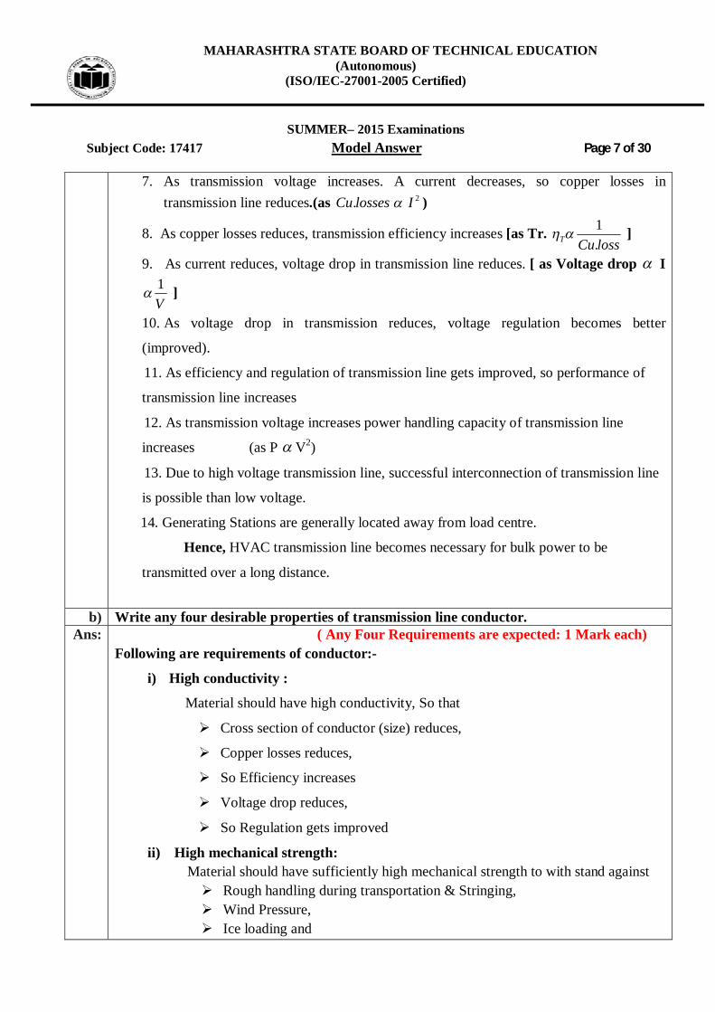
7. As transmission voltage increases. A current decreases, so copper losses in transmission line reduces.(as 2. IlossesCu )
8. As copper losses reduces, transmission efficiency increases [as Tr. lossCuT .1 ]
9. As current reduces, voltage drop in transmission line reduces. [ as Voltage drop I
V1 ]
10. As voltage drop in transmission reduces, voltage regulation becomes better
(improved).
11. As efficiency and regulation of transmission line gets improved, so performance of
transmission line increases
12. As transmission voltage increases power handling capacity of transmission line
increases (as P V2)
13. Due to high voltage transmission line, successful interconnection of transmission line
is possible than low voltage.
14. Generating Stations are generally located away from load centre.
Hence, HVAC transmission line becomes necessary for bulk power to be
transmitted over a long distance.
b) Write any four desirable properties of transmission line conductor.
Ans: ( Any Four Requirements are expected: 1 Mark each) Following are requirements of conductor:-
i) High conductivity :
Material should have high conductivity, So that
Cross section of conductor (size) reduces,
Copper losses reduces,
So Efficiency increases
Voltage drop reduces,
So Regulation gets improved
ii) High mechanical strength: Material should have sufficiently high mechanical strength to with stand against
Rough handling during transportation & Stringing, Wind Pressure, Ice loading and
MAHARASHTRA STATE BOARD OF TECHNICAL EDUCATION (Autonomous)
(ISO/IEC-27001-2005 Certified)
SUMMER– 2015 Examinations
Subject Code: 17417 Model Answer Page 8 of 30
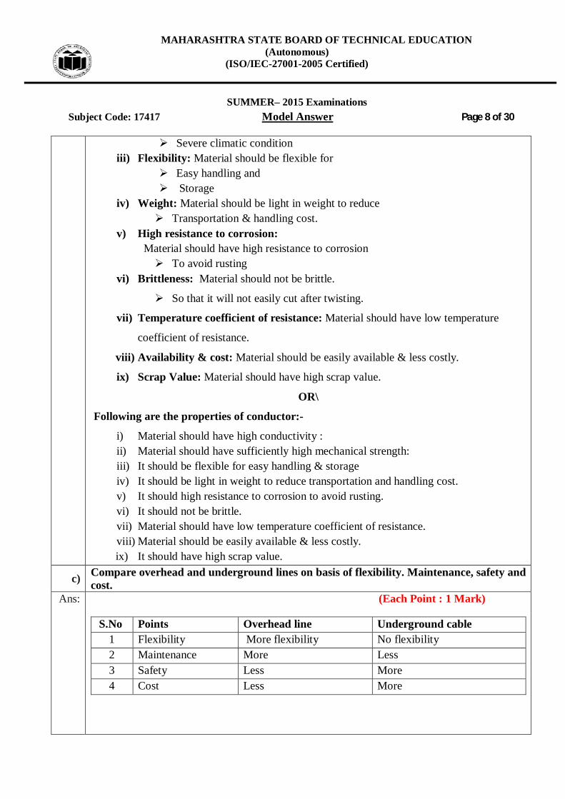
Severe climatic condition iii) Flexibility: Material should be flexible for
Easy handling and Storage
iv) Weight: Material should be light in weight to reduce Transportation & handling cost.
v) High resistance to corrosion: Material should have high resistance to corrosion To avoid rusting
vi) Brittleness: Material should not be brittle.
So that it will not easily cut after twisting.
vii) Temperature coefficient of resistance: Material should have low temperature
coefficient of resistance.
viii) Availability & cost: Material should be easily available & less costly.
ix) Scrap Value: Material should have high scrap value.
OR\
Following are the properties of conductor:-
i) Material should have high conductivity : ii) Material should have sufficiently high mechanical strength: iii) It should be flexible for easy handling & storage iv) It should be light in weight to reduce transportation and handling cost. v) It should high resistance to corrosion to avoid rusting. vi) It should not be brittle. vii) Material should have low temperature coefficient of resistance. viii) Material should be easily available & less costly. ix) It should have high scrap value.
c) Compare overhead and underground lines on basis of flexibility. Maintenance, safety and cost.
Ans: (Each Point : 1 Mark)
S.No Points Overhead line Underground cable 1 Flexibility More flexibility No flexibility 2 Maintenance More Less 3 Safety Less More 4 Cost Less More

MAHARASHTRA STATE BOARD OF TECHNICAL EDUCATION (Autonomous)
(ISO/IEC-27001-2005 Certified)
SUMMER– 2015 Examinations
Subject Code: 17417 Model Answer Page 9 of 30 d) State specific voltage level and material used for (i) RCC pole (ii) Steel tower
Ans: (Each Voltage Level: 1 Mark & Material Used: 1 Mark-Total 4 Mark)
RCC pole: Maximum 11 KV & for L.T up to 440 V.
material used -Steel rod with cement concrete and well cured in water
Steel tower : 66 KV and above e.g. 110KV, 66KV,132 KV, 220KV ,
440 KV,765KV
material used- Steel towers are fabricated from galvanized angle ‘K’ strip
e) Discuss any two methods of improving string efficiency Ans: The Methods of Improving String Efficiency:-
1) By reducing value of ‘m’ or (‘k’) by using longer cross arm.
2) By Making of ‘m’ or (‘k’) equal to zero
3) By grading Insulator.
4) By Using guard ring.
Explanation:- (Any Two Method are expected: 2 Mark each)
1) By reducing value of ‘m’ or (‘k’) by using longer cross arm:-
or equivalent diagram The value of ‘m’ can be decreased by reducing value of shunt capacitance (C1) since m = C1/C. In order to reduce value shunt capacitance (C1) distance of string of insulator from tower must be increased. i.e by using longer cross arm. Due to this value of shunt capacitance (C1) reduces.
2) By Making of ‘m’ or (‘k’) equal to zero:-
or equivalent diagram

MAHARASHTRA STATE BOARD OF TECHNICAL EDUCATION (Autonomous)
(ISO/IEC-27001-2005 Certified)
SUMMER– 2015 Examinations
Subject Code: 17417 Model Answer Page 10 of 30
If an insulating material or any non conducting material of high strength is
used for connection between two disc insulators in a string instead of using steel part.
Than value of Shunt Capacitance (C1) becomes Zero, therefore value of ‘m’
becomes zero (since m = C1/C) So string efficiency becomes 100%.
3) By grading Insulator :-
or equivalent diagram
In this method, disc insulators of different dimensions are so selected that each disc has different capacitance. The assembly in the string of suspension insulator is made in such a way that the top unit insulator has less dimensions. (Less capacitance) (C A) and dimensions of insulators progressively goes on increasing i.e bottom unit has maximum capacitance due to large dimensions of insulators. In this way it equalizer potential distribution across the string and therefore increases string efficiency. 4) By Using guard ring :-
or equivalent diagram Guard ring is a metal ring electrically connected to conductor and surrounding the
bottom insulator.
Due to guard ring leakage current through all discs in a string is same.
So, we will get uniform voltage distribution along the string of suspension
insulator, In this way string efficiency increases.

MAHARASHTRA STATE BOARD OF TECHNICAL EDUCATION (Autonomous)
(ISO/IEC-27001-2005 Certified)
SUMMER– 2015 Examinations
Subject Code: 17417 Model Answer Page 11 of 30 f) A 3 - ph overhead line is being supported by three disc insulators. The potential across
line unit is 17.5 KV. Assume that shunt capacitance between each insulator and each metal work of tower to be 1/10th of capacitance of insulator. Calculate (i) Line voltage (ii) String efficiency
Ans: i) Ratio of capacitance ‘m’ :-
m= 1.0101
------------------------------------------- (1/2 Mark)
k = m = 0.1
V3 = V1 (1+ 3m+m2 )
2)1.0()1.0(315.17
= V1
V1 = 13.358 KV ---------------------------------------- (1/2 Mark)
)1(12 mVV
)1.01(358.132 V
KVV 6938.142 ---------------------------------------- (1/2 Mark)
Voltage across string = Vph = V1 +V2+ V3 Vph = 45.55 KV ------------------------------------------ (1/2 Mark) ii) The line voltage VL = phV3
VL = 55.453 VL = 78.89 KV----------------------------------------------- (1 Mark) iii) String efficiency :-
String 1003
00
VVph
String 1005.173
55.450
0
String 00
00 76.86 ------------------------------------------------ (1 Mark)
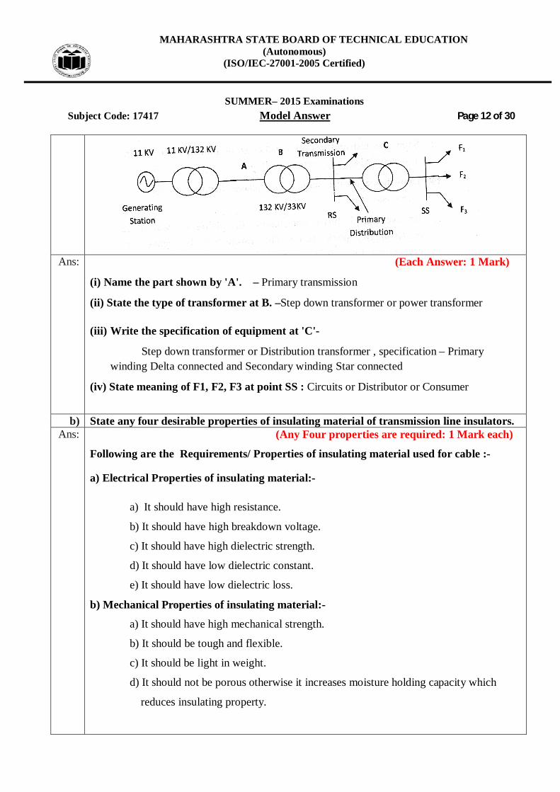
Q.3 Attempt any FOUR of the following : 16 Marks a) Study Figure No. 1 and answer following questions:
(i) Name the part shown by 'A'. (ii) State the type of transformer at ‘B’. (iii) Write the specification of equipment at 'C'. (iv) State meaning of F1, F2, F3 at point SS.
MAHARASHTRA STATE BOARD OF TECHNICAL EDUCATION (Autonomous)
(ISO/IEC-27001-2005 Certified)
SUMMER– 2015 Examinations
Subject Code: 17417 Model Answer Page 12 of 30
Ans: (Each Answer: 1 Mark)
(i) Name the part shown by 'A'. – Primary transmission
(ii) State the type of transformer at B. –Step down transformer or power transformer
(iii) Write the specification of equipment at 'C'-
Step down transformer or Distribution transformer , specification – Primary winding Delta connected and Secondary winding Star connected
(iv) State meaning of F1, F2, F3 at point SS : Circuits or Distributor or Consumer
b) State any four desirable properties of insulating material of transmission line insulators. Ans: (Any Four properties are required: 1 Mark each)
Following are the Requirements/ Properties of insulating material used for cable :-
a) Electrical Properties of insulating material:-
a) It should have high resistance.
b) It should have high breakdown voltage.
c) It should have high dielectric strength.
d) It should have low dielectric constant.
e) It should have low dielectric loss.
b) Mechanical Properties of insulating material:-
a) It should have high mechanical strength.
b) It should be tough and flexible.
c) It should be light in weight.
d) It should not be porous otherwise it increases moisture holding capacity which
reduces insulating property.

MAHARASHTRA STATE BOARD OF TECHNICAL EDUCATION (Autonomous)
(ISO/IEC-27001-2005 Certified)
SUMMER– 2015 Examinations
Subject Code: 17417 Model Answer Page 13 of 30
c) Chemical Properties of insulating material:-
a) It should not be hygroscopic (which absorbs moisture).
b) It should have high resistance to acid & alkaline.
c) It should have high resistance to oil.
d) Thermal Properties of insulating material:-
a) It should have high thermal conductivity.
b) Co-efficient of thermal expansion should be low.
c) It should be non -inflammable.
d) It should withstand at high temperature.
e) Ii should have thermal Stability.
e) General Properties of insulating material:-
a) It should have longer life.
b) It should have low cost.
OR
Requirements/ Properties of insulating material:- (Any Four properties expected)
1. It should have high resistance
2. It should have high breakdown voltage.
3. It should have high dielectric strength.
4. It should have low dielectric constant.
5. It should have low dielectric loss.
6. It should have high mechanical strength.
7. It should be tough and flexible.
8. It should be light in weight.
9. It should not be porous.
10. It should not be hygroscopic.
11. It should have high resistance to oil, acid. 12. It should have high thermal conductivity. 13. Co-efficient of thermal expansion should be low. 14. It should be non -inflammable. 15. It should have thermal Stability. 16. It should have longer life. 17. It should have low cost.

MAHARASHTRA STATE BOARD OF TECHNICAL EDUCATION (Autonomous)
(ISO/IEC-27001-2005 Certified)
SUMMER– 2015 Examinations
Subject Code: 17417 Model Answer Page 14 of 30
c) Suggest with reasons the type of insulators used for following voltage levels of transmission and distribution system. (i) 11 KV Distributors (ii) 132 KV Feeder (iii) 400 KV Tower (iv) 33 KV Distributor
Ans: (Each Suggestion of Names : 1 Mark each) (i) 11 KV Distributors :- Pin type insulator (for horizontal configuration line) or Shakale
type insulator (for vertical configuration line) (ii) 132 KV Feeder :- Disc or Suspension type insulator iii) 400 KV Tower :- Disc or Suspension type insulator (iv) 33 KV:- Disc or Suspension type insulator/ Pin type insulator
d) Identify the effect shown in Figure No. 2. Also state factors affecting the effect.
Ans: Identify the effect :- It is a Skin effect On following factors skin Effect depends: (Each factor : 1 Mark)
1. Supply frequency: As frequency increases skin effect increases.
2. Cross section of conductor: Skin effect increases with increase in diameter of conductor.
3. Solid conductors have more skin effect than stranded conductors.
4. Permeability of conductor material
e) Discuss any two methods of reducing corona. Ans: Methods of reducing corona : (Any Two method expected: 2 Mark each)
1. By increasing distance between two conductor i.e. by using longer cross arm.
2. By using larger size(diameter) of conductor e.g./ using ACSR, bundled conductor
3. By using smooth body conductor and hardware.

MAHARASHTRA STATE BOARD OF TECHNICAL EDUCATION (Autonomous)
(ISO/IEC-27001-2005 Certified)
SUMMER– 2015 Examinations
Subject Code: 17417 Model Answer Page 15 of 30 f) State the effect of unity power factor efficiency and regulation of transmission line.
Ans: Efficiency:- (2 Mark)
As power factor increases (unity power factor), current decreases, so Copper losses
decreases, Hence transmission efficiency increases & vice versa.
Regulation:- (2 Mark)
As power factor increases(unity power factor),, current decreases, So Voltage drop in
transmission line decreases, As a result, regulation get improved (decrease) an vice versa.
OR Student may write this way
Vector Diagram for Unity Power Factor: (4 Mark)
At UPF receiving voltage is less than Sending end hence regulation is positive
Q.4 Attempt any FOUR of the following : 16 Marks
a) Show the transposition of conductors of transmission line by a sketch. Also state necessity of it.
Ans: (Figure : 2 Mark & Necessity: 2 Mark)
Transposition of line conductors means changing the positions of 3- phases on the line supports twice over the total length of the line.
Figure of Transposition of conductor:

MAHARASHTRA STATE BOARD OF TECHNICAL EDUCATION (Autonomous)
(ISO/IEC-27001-2005 Certified)
SUMMER– 2015 Examinations
Subject Code: 17417 Model Answer Page 16 of 30
Necessity of transposition :-
Due transposition of conductor inductance of each line is same LA = LB = LC, So drop
due to inductive reactance in each line is same so voltage at receiving end between any
two line become same.
So to obtain same voltage in any two line at receiving end (VRY = VYB = VRB)
transposition is necessary.
Radio interferences are less due to transposition.
b) Draw the equivalent circuit and phasor diagram of short transmission line. Ans: Equivalent circuit : (Circuit diagram: 2 Mark & Vector Diagram: 2 Mark)
Vector Diagram:
c) An overhead 3 - phase transmission line delivers 5 MW at 22 KV at 0.8 lagging power factor. The resistance and reactance of each conductor is 4 and 6 , respectively. Determine sending end voltage and percentage regulation.

MAHARASHTRA STATE BOARD OF TECHNICAL EDUCATION (Autonomous)
(ISO/IEC-27001-2005 Certified)
SUMMER– 2015 Examinations
Subject Code: 17417 Model Answer Page 17 of 30
Ans: Given Data:-
PR = 5MW VR = 22KV P.F. = 0.8 lag Rph = 4 ohm Xph = 6 ohm
To calculate current:
Power P = phforIV LL 3cos3
cos3
LRVPI
-------------------------- (1 /2Mark)
8.02235000
I
ampI 01996.164 ----------------------------- (1 /2Mark)
To calculate value of sin :
6.0sin;8.0 RRCos -------------------------------------------------------- (1/2 Mark)
3RL
RphVV
322
RphV
VVorKVV RphRph3107017.127017.12 -------------------- (1/2 Mark)
To calculate Sending end voltage: Sending end phase voltage ( VSph)=
= VRph +I (RPh Cos ØR + XPh Sin ØR) =12.7017103 +164.01996 (40.8 + 60.6)
= 13817.0357 V
=13.8170357 KV ------------------------- (1/2 Mark)
Sending End Line Voltage = sphSL VV 3
8170357.133 SLV
= 23.9318 KV ------------------------- (1/2 Mark) To calculate voltage regulation:
% Voltage Regulation = 100
PhR
PhRPhS
VVV
= 1007017.12
7017.128170357.13
= 8.78 % --------------------------------------- (1 Mark)

MAHARASHTRA STATE BOARD OF TECHNICAL EDUCATION (Autonomous)
(ISO/IEC-27001-2005 Certified)
SUMMER– 2015 Examinations
Subject Code: 17417 Model Answer Page 18 of 30 d) State two advantages and two disadvantages of HVDC transmission.
Ans: (Each Advanatges:1 Mark & Disadvantages: 1 Mark, Total 4 Mark)
Advantages of HVDC Transmission System:- (Any Two Expected)
1) The basic D.C transmission line requires only 2 Conductor. (+ ve & - Ve) and if
ground is used as a return path, then only one conductor is sufficient.
2) If ground is used as return path, then only 2 conductors are sufficient for double
circuit.
3) As number of conductor required are less, so load on tower is less. This make
Tower design simple and lighter.
4) Tower required less ground area as its base is less than AC tower. ( Right Of Way )
So land use benefits are more.
5) No intermediate substation is required like HVAC transmission line.
6) Due to above advantages, Cost of transmission line per KM is less.
7) Skin effect is absent.
8) No proximity effect.
9) Less radio interference.
10) No Ferranti effect.
11) String efficiency 100%
12) Low corona loss.
13) Copper losses are less, transmission efficiency is more.(As dc resistance is less than
AC resistance by 1.6 times)
14) As Copper loss are less So transmission efficiency is more
15) As effect of L & C is absent and value of DC resistance of conductor is less, so
voltage drop in transmission line is less.
16) Voltage regulation is better than HVAC transmission line.
17) Voltage control easy for long distance HVDC transmission line.
18) Power flow control is easy for long distance transmission.
19) There is no limit for transmission of power.
20) Asynchronous tie possible.
21) HVDC line has more stability than HVAC.
MAHARASHTRA STATE BOARD OF TECHNICAL EDUCATION (Autonomous)
(ISO/IEC-27001-2005 Certified)
SUMMER– 2015 Examinations
Subject Code: 17417 Model Answer Page 19 of 30
22) If power is to be transmitted through cable than there is no limit on the length of
cable as charging current is absent
23) There is no need of reactive power compensation.
24) Two transmission lines of different frequencies can be inter connected to grid system
through HVDC link OR Asynchronous tie is possible through HVDC link
Disadvantages HVDC Transmission System: (Any Two Expected)
1) It is difficult to step up and step down DC voltage like AC voltage.
2) Special cooling arrangements are necessary for converter, so it increases cost of
substation.
3) Cost of DC substation is more than AC substation, due to additional equipment
required like rectifier, inverter etc.
4) Maintenance cost of DC substation is more due to additional equipment.
5) Space required for DC substation is more due to additional equipment
6) Losses in DC substation are more due to additional equipment.
7) Over load capacity Converter is very less.
8) Reliable DC circuit breakers are not available like AC circuit breakers.
9) Cost of DC circuit breaker is more than AC circuit breaker.
10) If ground is used as the return path, then it leads
Corrosion of underground metallic structure of buildings, pipes, etc.
Causes disturbance in underground communication cable.
11) HVDC is economical only for bulk amount of power is to be transmitted
(1000MW and above) and for long distances (800KM and above) Transmission
line.
MAHARASHTRA STATE BOARD OF TECHNICAL EDUCATION (Autonomous)
(ISO/IEC-27001-2005 Certified)
SUMMER– 2015 Examinations
Subject Code: 17417 Model Answer Page 20 of 30
e) Compare EHVAC and HVDC transmission line on basis of voltage level, amount of power delivered, and transmission cost and interference effect.
Ans: ( Each Point : 1 Mark)
S.No Points EHV A.C H.V.D.C 1 Voltage level More (765 KV) Less (500KV) 2 Power Delivered Less than HVDC More 3 Transmission line
cost/km More at a distance of Transmission line 500 Km below
Less for long distances Transmission line (800KM and above )
4 Radio interference Present (More) Absent ( less)
f) List any four basic components present in distribution system. Also state function each. Ans: ( Each Component: 1/2 Mark & Each Function: 1/2 Mark, Total : 4 Mark)
Following are the different components of distribution system:-
1. Feeder (Primary distribution): It is 3-Ph Three-Wire System and voltage level is 11/22/33 KV depending upon load
2. Distribution Transformer (DTC): It is step down transformer, its step-down 11/22/33 KV to utilization voltage 3-Ph 400 volt, It is designed Delta-Star
3. Distributor (Secondary distribution System): It is 3-Ph Four-Wire System (R-Y-B-N) and Voltage level 3-Ph 400 Volt, for single phase supply voltage is 230 volt
4. Service mains: It is a cable connecting distributor (conductor) to consumer’s terminals energy meter. Size of service wire depends on load.
Q.5 Attempt any FOUR of the following : 16 Marks
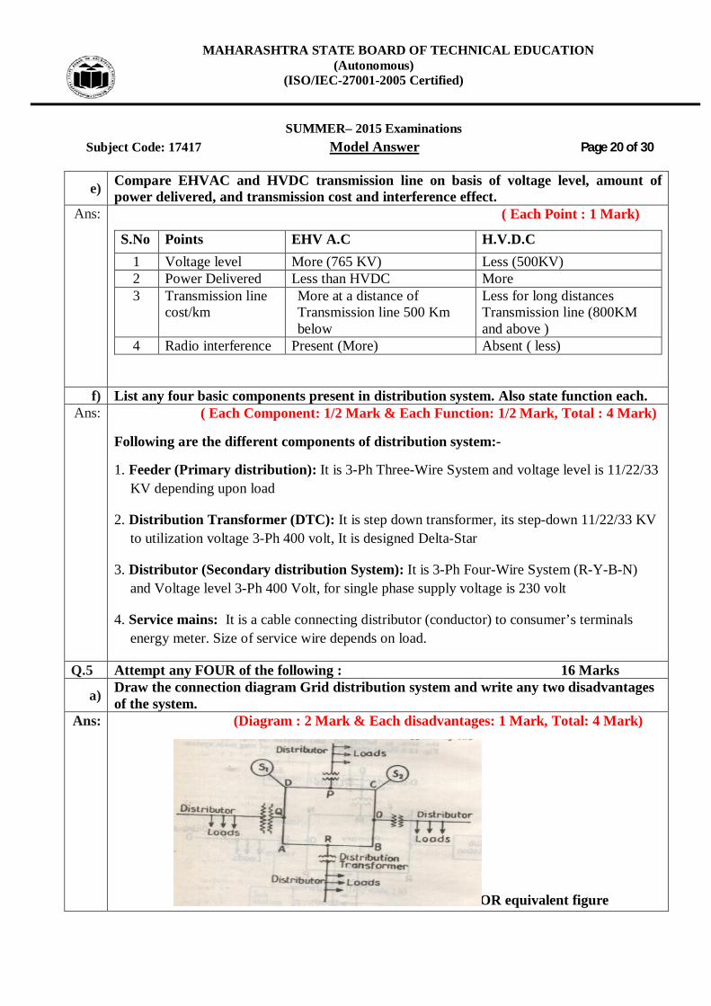
a) Draw the connection diagram Grid distribution system and write any two disadvantages of the system.
Ans: (Diagram : 2 Mark & Each disadvantages: 1 Mark, Total: 4 Mark)
OR equivalent figure

MAHARASHTRA STATE BOARD OF TECHNICAL EDUCATION (Autonomous)
(ISO/IEC-27001-2005 Certified)
SUMMER– 2015 Examinations
Subject Code: 17417 Model Answer Page 21 of 30
Disadvantages:- ( Any Two Expected)
1. Layout & design is complicated. 2. Initial cost & Errection cost is high because to two incoming feeders. 3. Time required for completion of layout is more. 4. Extra care should be taken at the time of repairing & maintenance, because
feeders form a closed loop. b) Draw the layout of ring distribution scheme and write any two advantages of the same.
Ans: (Diagram : 2 Mark & Each advantages: 1 Mark, Total: 4 Mark)
Advantages:- (Any Two Expected)
1. Supply to distribution transformer centre is given through two different Feeders
2. Reliability to maintain supply is more even when there is a fault on any one feeder.
3. Reliability to maintain supply is more even when there was maintenance on any one
feeder.
4. There are less voltage fluctuations at consumer’s terminals.
MAHARASHTRA STATE BOARD OF TECHNICAL EDUCATION (Autonomous)
(ISO/IEC-27001-2005 Certified)
SUMMER– 2015 Examinations
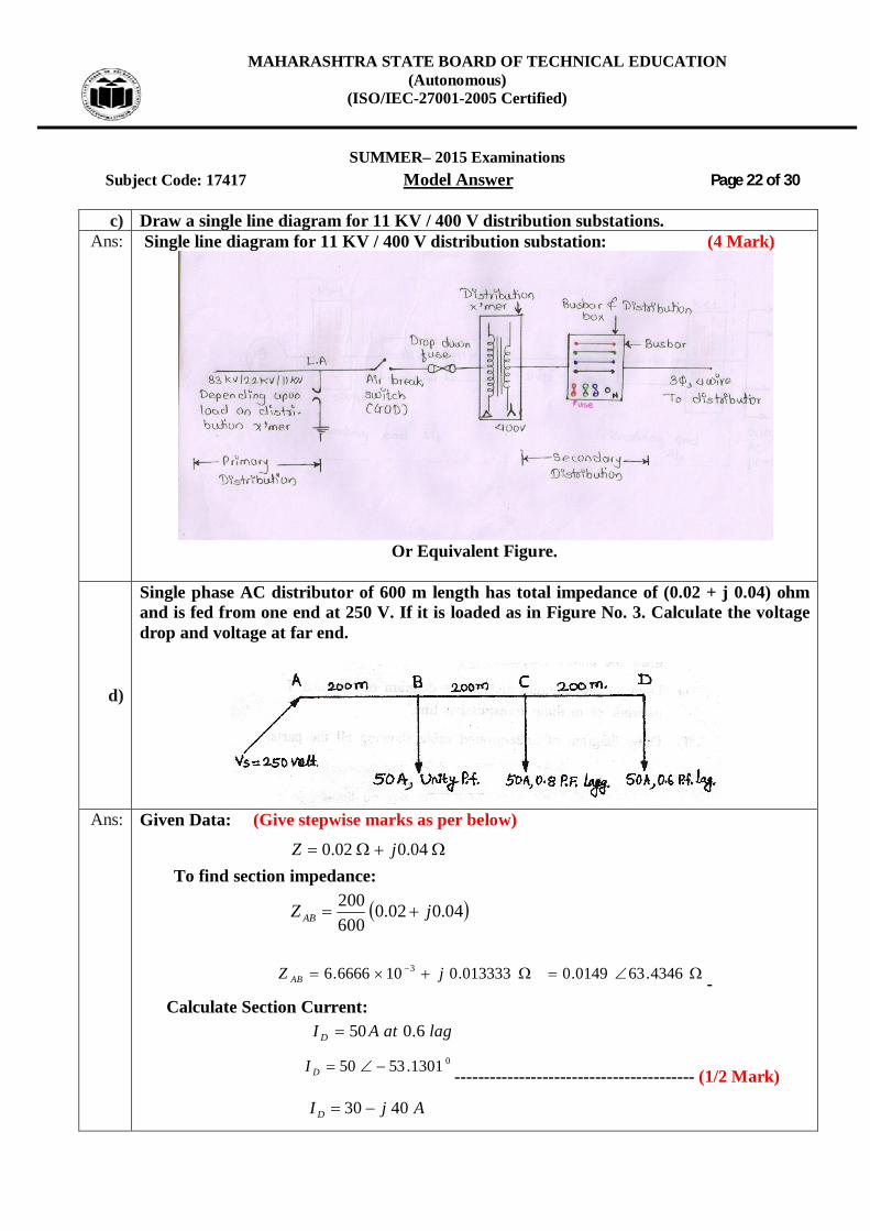
Subject Code: 17417 Model Answer Page 22 of 30 c) Draw a single line diagram for 11 KV / 400 V distribution substations.
Ans: Single line diagram for 11 KV / 400 V distribution substation: (4 Mark)
Or Equivalent Figure.
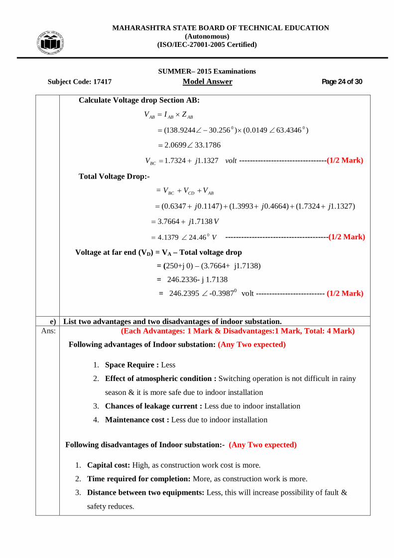
d)
Single phase AC distributor of 600 m length has total impedance of (0.02 + j 0.04) ohm and is fed from one end at 250 V. If it is loaded as in Figure No. 3. Calculate the voltage drop and voltage at far end.
Ans: Given Data: (Give stepwise marks as per below)
04.002.0 jZ To find section impedance:
04.002.0600200 jZ AB
4346.630149.0013333.0106666.6 3 jZ AB -
Calculate Section Current: lagatAI D 6.050
01301.5350 DI ----------------------------------------- (1/2 Mark)
AjI D 4030

MAHARASHTRA STATE BOARD OF TECHNICAL EDUCATION (Autonomous)
(ISO/IEC-27001-2005 Certified)
SUMMER– 2015 Examinations
Subject Code: 17417 Model Answer Page 23 of 30
Given .8.050 lagatAI C 087.3650 ---------------------------------------------- (1/2 Mark)
AjIC 3040
Given unityatAI B 50 0050 ------------------------------------------------------ (1/2 Mark) AjI B 050 To calculate the section current: ICD = ID
DCBC III -
)3040( jIBC )4030( j
AjI BC 7070
AI BC0459949.98
DCBAB IIII BCBAB III
)7070()050( jjI AB
70120 jI AB
0256.309244.138 ABI ----------------------------------------- (1/2 Mark)
Calculate Voltage drop: )( CDVCD
CDCDCD ZIV
)4349.630149.0()130.5350( 00
2474.10645.0
1147.06347.0 jVCD ------------------------------------- (1/2 Mark)
Voltage drops in section BC (VBC):
BCBCBC ZIV
)4349.630149.0()459949.98( 00
4349.18475.1
voltjVBC 4664.03993.1
MAHARASHTRA STATE BOARD OF TECHNICAL EDUCATION (Autonomous)
(ISO/IEC-27001-2005 Certified)
SUMMER– 2015 Examinations
Subject Code: 17417 Model Answer Page 24 of 30
Calculate Voltage drop Section AB:
ABABAB ZIV
)4346.630149.0()256.309244.138( 00
1786.330699.2
voltjVBC 1327.17324.1 ---------------------------------(1/2 Mark)
Total Voltage Drop:-
= ABCDBC VVV
)1327.17324.1()4664.03993.1()1147.06347.0( jjj
Vj 7138.17664.3
V046.241379.4 ---------------------------------------(1/2 Mark)
Voltage at far end (VD) = VA – Total voltage drop
= (250+j 0) – (3.7664+ j1.7138)
= 246.2336- j 1.7138
= 246.2395 -0.39870 volt -------------------------- (1/2 Mark)
e) List two advantages and two disadvantages of indoor substation. Ans: (Each Advantages: 1 Mark & Disadvantages:1 Mark, Total: 4 Mark)
Following advantages of Indoor substation: (Any Two expected)
1. Space Require : Less
2. Effect of atmospheric condition : Switching operation is not difficult in rainy
season & it is more safe due to indoor installation
3. Chances of leakage current : Less due to indoor installation
4. Maintenance cost : Less due to indoor installation
Following disadvantages of Indoor substation:- (Any Two expected)
1. Capital cost: High, as construction work cost is more.
2. Time required for completion: More, as construction work is more.
3. Distance between two equipments: Less, this will increase possibility of fault &
safety reduces.
MAHARASHTRA STATE BOARD OF TECHNICAL EDUCATION (Autonomous)
(ISO/IEC-27001-2005 Certified)
SUMMER– 2015 Examinations
Subject Code: 17417 Model Answer Page 25 of 30
4. Access for incoming & outgoing line: Difficult access for incoming & outgoing lines
because of indoor installation.
5. Cooling arrangement: Natural cooling is not available so artificial cooling
arrangement is required which increases energy consumption charges due to indoor
installation.
6. Availability of natural light: Natural light is not available in day time, so there is need
of illumination even during a day time. which increases energy consumption charges
due to indoor installation
7. Detection of fault: Difficult, as all equipments are not easily viewed.
8. Replacement of equipment: Difficult, due to indoor installation.
9. Future expansion: Expansion of substation is not easily possible whenever needed
because of construction work. Also it require more time & cost.
10. In case of accident: In case of accident there is more risk & damage to other
equipments than outdoor substation.
f) Give classification of substation on basis of :(i) Service requirement (ii) Construction
Ans: According to nature of service or Application:- ( Any Four expected: 1/2 Mark each)
1. Transformer Sub-station
2. Switching sub-station
3. Power Factor correction sub-station
4. Frequency changer sub-station
5. Converting sub-station
6. Industrial Sub-station (Bulk Supply Industrial Consumer Substation)
7. Traction substation
8. Mining Substation
9. Mobile Substation
2. According to Method of Construction:- ( Any Four expected: 1/2 Mark each)
1. Indoor Substation
2. Outdoor Substation
3. Gas insulated Substation

MAHARASHTRA STATE BOARD OF TECHNICAL EDUCATION (Autonomous)
(ISO/IEC-27001-2005 Certified)
SUMMER– 2015 Examinations
Subject Code: 17417 Model Answer Page 26 of 30
4. Underground Substation
5. Pole mounted substation
6. Plinth Substation
7. Compact/prefabricated substation
Q.6 Attempt any Four of the following : 16 Marks a) “Power factor affects the transmission efficiency and regulation.” Justify.
Ans: (4 Mark) We know that,
phforIVandphforVIP LL 3cos31cos When same power is to be transmitted over same distance at same transmission voltage
Then current is inversely proportional to the power factor (
cos
1I ) from this equation, it is
clear that as power factor increases, current decreases, as a result performance of transmission line
i.e. efficiency and regulation is gets improved and vice versa. i.e.
Efficiency:-
As power factor increases, current decreases, so Copper losses decreases, Hence transmission
efficiency increases & vice versa.
Regulation:-
As power factor increases, current decreases, So Voltage drop in transmission line decreases,
As a result, regulation get improved (decrease) an vice versa.
OR
Effect of poor power factor on efficiency and voltage regulation of transmission line.
We know that,
phforIVandphforVIP LL 3cos31cos When same power is to be transmitted over same distance at same transmission voltage then
current is inversely proportional to the power factor
Effect of poor power factor on efficiency:- When power factor of load reduces current drawn by transmission line increases so copper
losses in transmission line increases, hence transmission efficiency reduces.
MAHARASHTRA STATE BOARD OF TECHNICAL EDUCATION (Autonomous)
(ISO/IEC-27001-2005 Certified)
SUMMER– 2015 Examinations
Subject Code: 17417 Model Answer Page 27 of 30
Effect of poor power factor on voltage Regulation:- When power factor of load reduces current through transmission line increases, so voltage
drop in transmission line (due to resistance & inductive reactance) increases so regulation increases. (Become Poor)
b) State the factors considered for designing feeders and distributors. Ans: (Feeder : 2 Mark & Distributors : 2 Mark)
Following factors are to be considered while designing the Feeder:
(Any Two Point expected)
1) Current carrying capacity of conductor:-
Conductor should have high current carrying capacity. While voltage drop
consideration is relatively not so important
It is because voltage drop in feeder can be adjusted with the help of tapings of
distribution transformer manually or by using AVR (Automatic Voltage Regulator)
2) Need:
Depending upon application design of distribution system should be selected i.e.
whether continuity of supply is important or not so important
Example: 1) Use Radial distribution system in rural area
2) Use Ring main distribution system in urban area
3) Use Grid distribution system where continuity of supply is important.
e.g. Supply to - electric traction, TV broadcasting centre, AIR, telephone exchange,
major hospitals, important government buildings and major industries
3) Availability of power: It should be available whenever needed
4) Maintenance: It should be low, easy, less costly & less time consuming.
Points to be considered while designing the distributor: (Any Two Point expected)
Following factors are to be considered while designing the distributor.
1) Voltage drop limit: It should be within permissible limit ( 6%)
2) Length of distributor: There is limit to length of distributor due to voltage drop
permissible limit.

MAHARASHTRA STATE BOARD OF TECHNICAL EDUCATION (Autonomous)
(ISO/IEC-27001-2005 Certified)
SUMMER– 2015 Examinations
Subject Code: 17417 Model Answer Page 28 of 30
3) Size (cross-section) of conductor: - Cross section of conductor should be of
sufficient current carrying capacity.
4) Availability of power: - Power should be available whenever needed (Power must
be available to all consumers on demand that they may require from time to time.)
5) Maintenance: It should be low & less time consuming.
c) Suggest suitable type of substation for following applications with suitable reasons.
(i) Metropolitan city (ii) Hill station Ans: ( Each Type : 2 Mark, Total: 4 Mark)
(i) Metropolitan city :- Underground / Indoor due to shortage of space (Land ) (ii) Hill station :- Indoor due to high wind pressure / Ice fall rain OR
:- Out door as space available is more
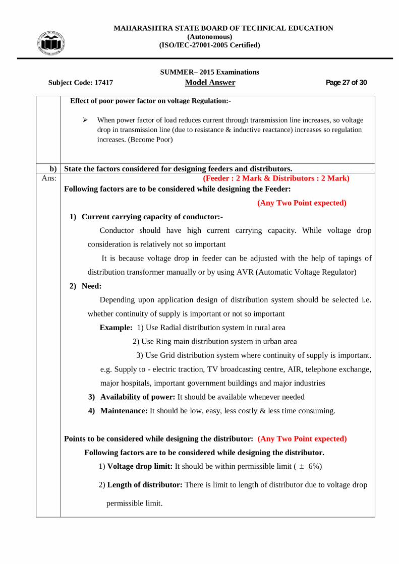
d) Write equations for sending end voltage and efficiency for medium transmission line with End condenser method and also draw the phasor diagram.
Ans: Equations for sending end voltage:- (1 Mark)
Vs RTRTR XRIV sincos OR
Sending end voltage, LSR XjRIV . Equations for efficiency: (1 Mark)
% Efficiency = 100 lossescoppertotalpoweroutput
poweroutput OR
% Efficiency = 100 lossescoppertotalpoweroutput
poweroutput
OR % Efficiency =
cetanresistotalisR,WherePhase1for100RIP
PT
T2
R
R
OR % Efficiency =
phaseperofcetanresisisR,WherePhase3for100RI3P
P
ph2
R
R
MAHARASHTRA STATE BOARD OF TECHNICAL EDUCATION (Autonomous)
(ISO/IEC-27001-2005 Certified)
SUMMER– 2015 Examinations
Subject Code: 17417 Model Answer Page 29 of 30
Phasor Diagram: (2 Mark)
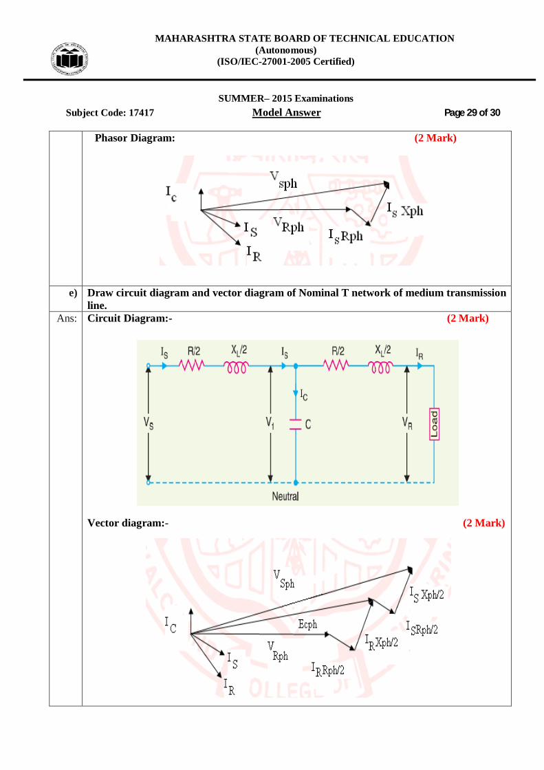
e) Draw circuit diagram and vector diagram of Nominal T network of medium transmission line.
Ans: Circuit Diagram:- (2 Mark)
Vector diagram:- (2 Mark)
MAHARASHTRA STATE BOARD OF TECHNICAL EDUCATION (Autonomous)
(ISO/IEC-27001-2005 Certified)
SUMMER– 2015 Examinations
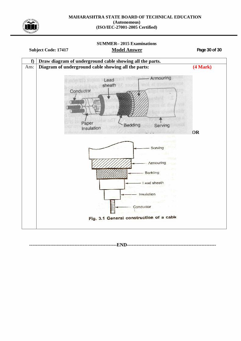
Subject Code: 17417 Model Answer Page 30 of 30 f) Draw diagram of underground cable showing all the parts.
Ans: Diagram of underground cable showing all the parts: (4 Mark)
OR
------------------------------------------------------END-------------------------------------------------------