Embed Size (px)
Citation preview

MAHARASHTRA STATE BOARD OF TECHNICAL EDUCATION (Autonomous)
(ISO/IEC-27001-2005 Certified)
SUMMER– 2018 Examinations
Subject Code: 17318 Model Answer Page 1 of 37
Important suggestions to examiners:
1) The answers should be examined by key words and not as word-to-word as given in the model answer scheme.
2) The model answer and the answer written by candidate may vary but the examiner may try to assess the understanding level of the candidate.
3) The language errors such as grammatical, spelling errors should not be given more importance. (Not applicable for subject English and communication skills)
4) While assessing figures, examiner may give credit for principle components indicated in a figure. The figures drawn by candidate and model answer may vary. The examiner may give credit for any equivalent figure drawn.
5) Credits may be given step wise for numerical problems. In some cases, the assumed constant values may vary and there may be some difference in the candidate’s answers and model answer.
6) In case some questions credit may be given by judgment on part of examiner of relevant answer based on candidate understands.
7) For programming language papers, credit may be given to any other program based on equivalent concept.
Q.1 A Attempt any SIX of the following : 12 Marks
a) Define form factor for a sine wave. State its value. Ans: 1. Form factor : ( Definition 1 Mark& Value: 1 Mark)
It is defined as the ratio of RMS value to the Average value of an alternating quantity
VALUEAVERAGEVALUERMSFF
Value of Form factor: 1.11 (for a sinusoidal quantity)
b) Define bandwidth of a series resonant circuit and give the expression for the same. Ans: Bandwidth of a series resonant circuit: (1 Mark)
The bandwidth of the series circuit is defined as difference in two half power frequencies.
LfHfBW
MAHARASHTRA STATE BOARD OF TECHNICAL EDUCATION (Autonomous)
(ISO/IEC-27001-2005 Certified)
SUMMER– 2018 Examinations
Subject Code: 17318 Model Answer Page 2 of 37 Expression of Bandwidth of a series resonant circuit:
Bandwidth BW is given by: LRBW (1 Mark)
c) State two advantages of three phase system over single phase system.
Ans: Advantages of 3-phase supply over 1-phase supply:(Any Two points each point 1 Mark)
1. Constant power output: The power delivered by a three phase supply is constant and that of single phase supply is oscillating.
2. Higher power: For the same copper size output of 3 phase supply is always higher than single phase supply.
3. Smaller conductor cross section: For given power, cross section area of copper is smaller as compared to single phase.
4. Self starting capability: Three phase motors are self-starting and single phase motors normally require a starter.
5. Vibrations: Three phase motors have less vibrations as compared to single phase motors.
d) State Fleming's Right hand rule.
Ans:
Fleming’s Right Hand Rule: ( 2 Mark)
Arrange three fingers of right hand mutually perpendicular to each other, if the first figure indicates
the direction of flux, thumb indicates the direction of motion of the conductor, then the
middle finger will point out the direction of inducted current.
e) State Faraday's laws of electromagnetic induction. Ans: First Law: - Whenever change in the magnetic flux linked with a coil or conductor, an EMF is
induced in it. OR Whenever a conductor cuts magnetic flux, an EMF is induced in
conductor. (1 Mark)
Second Law: - The Magnitude of induced EMF is directly proportional to (equal to) the rate of
change of flux linkages. (1 Mark)
e = N ddt
f) Define slip and slip speed. Ans: i) Slip:- (1 Mark)
It is the ratio the difference between the synchronous speed and actual speed of the rotor to

MAHARASHTRA STATE BOARD OF TECHNICAL EDUCATION (Autonomous)
(ISO/IEC-27001-2005 Certified)
SUMMER– 2018 Examinations
Subject Code: 17318 Model Answer Page 3 of 37
synchronous speed.
It is expression in percentage =
% Slip = S
S
NNN
ii) Slip speed = (1 Mark)
It is defined as the difference of synchronous speed and speed at which motor is rotating
NNS Where, Ns= Synchronous speed, N= Rotor speed
g) State any two speed control methods for three phase induction motor.
Ans:
Following methods to control the speed of 3 phase induction motor: (2 Mark)
(Any Two methods are expected)
The basic equation for speed of three ph. I.M. is given by
PfN .120
Speed can be controlled by
1. By Varying supply frequency (keeping voltage/freq ratio constant)
2. By changing number of poles of the stator winding (Pole changing control)
3. By controlling supply voltage
4. By inserting additional resistance in the rotor circuit (slip ring induction motor)
h) State the necessity of earthing. Ans:
Necessity of Earthing: ( Any Two point are expected) (2 Mark)
1. To provide an alternative path for the leakage current to flow towards earth.
2. To save human life from danger of electrical shock due to leakage current.
3. To protect high rise buildings structure against lightening stroke.
4. To provide safe path to dissipate lightning and short circuit currents.
5. To provide stable platform for operation of sensitive electronic equipment’s.
MAHARASHTRA STATE BOARD OF TECHNICAL EDUCATION (Autonomous)
(ISO/IEC-27001-2005 Certified)
SUMMER– 2018 Examinations
Subject Code: 17318 Model Answer Page 4 of 37
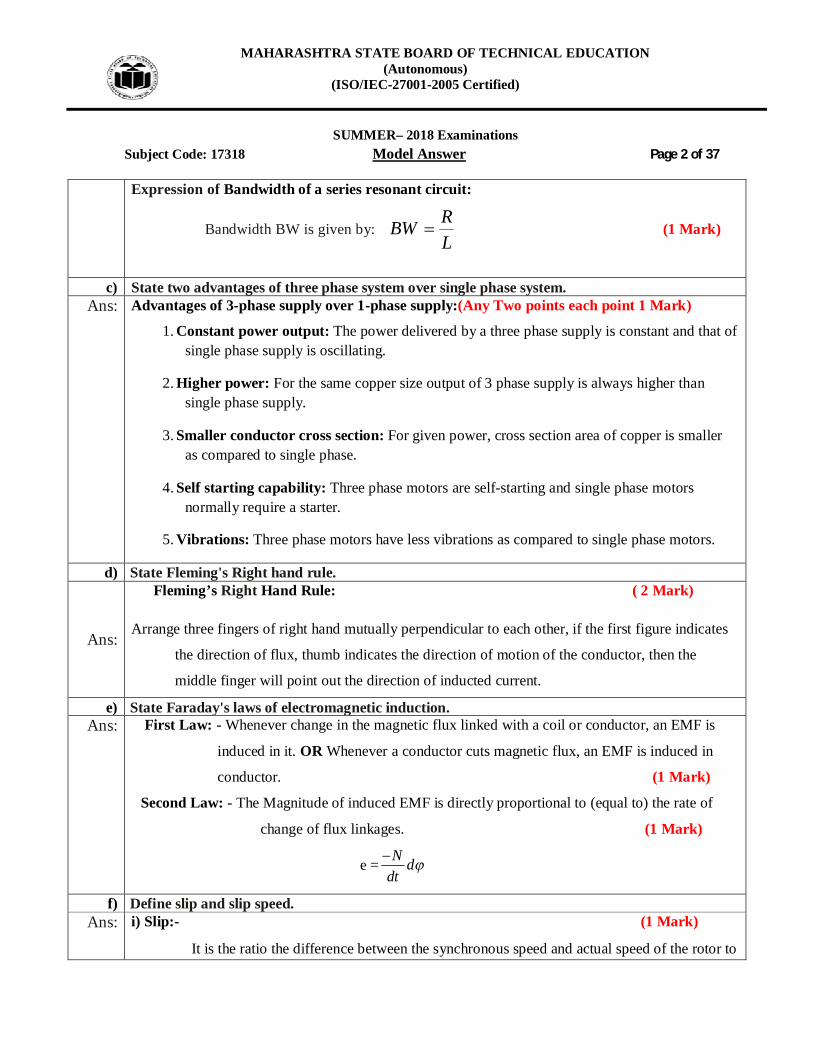
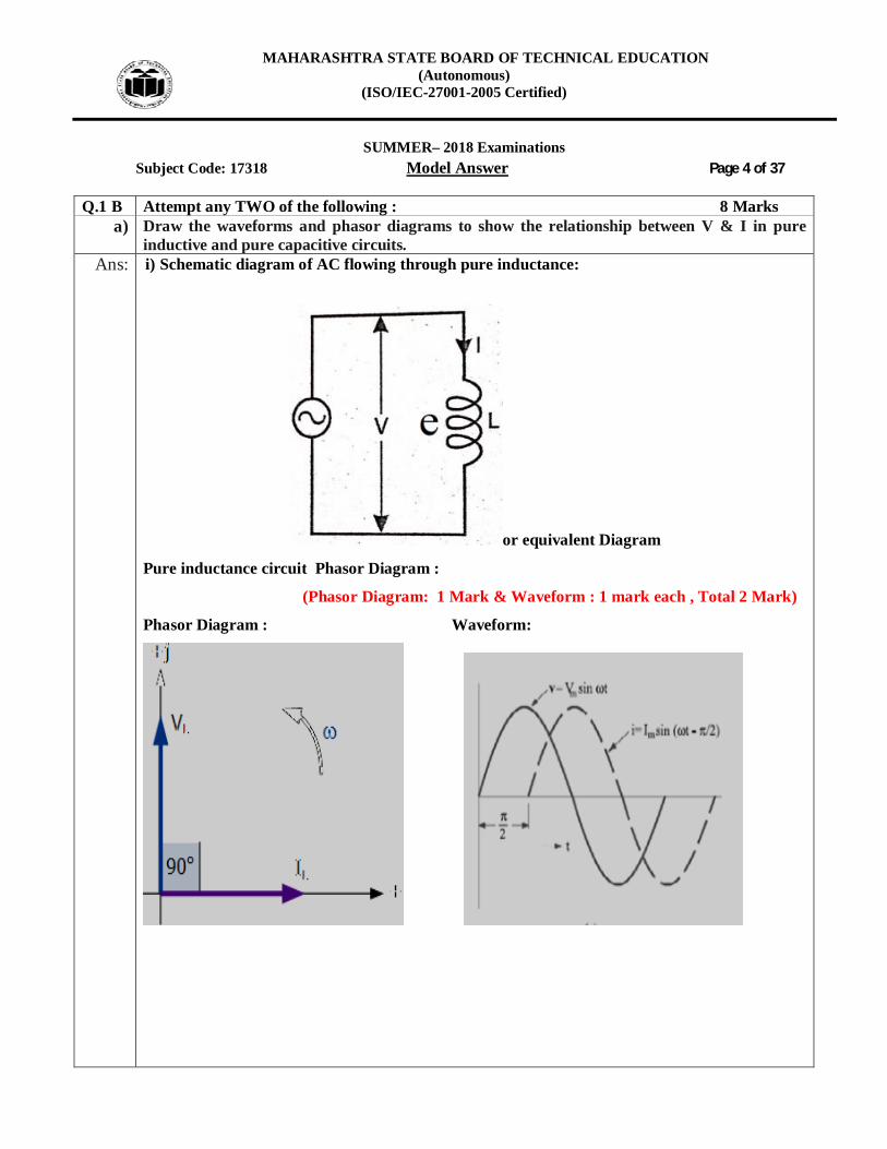
Q.1 B Attempt any TWO of the following : 8 Marks a) Draw the waveforms and phasor diagrams to show the relationship between V & I in pure
inductive and pure capacitive circuits. Ans: i) Schematic diagram of AC flowing through pure inductance:
or equivalent Diagram
Pure inductance circuit Phasor Diagram :
(Phasor Diagram: 1 Mark & Waveform : 1 mark each , Total 2 Mark)
Phasor Diagram : Waveform:

MAHARASHTRA STATE BOARD OF TECHNICAL EDUCATION (Autonomous)
(ISO/IEC-27001-2005 Certified)
SUMMER– 2018 Examinations
Subject Code: 17318 Model Answer Page 5 of 37
ii) Schematic diagram of AC flowing through pure capacitive:
or equivalent Diagram
Phasor Diagram : Waveform:
(Phasor Diagram: 1 Mark & Waveform : 1 Mark each , Total 2Mark)
b) Draw a neat labelled circuit diagram of three phase delta connected system and write
relationship between (i) Line voltage and phase voltage (ii) Line current and phase current Ans: Circuit Diagram of three phase delta connected system: ( 2 Marks)
or equivalent diagram
MAHARASHTRA STATE BOARD OF TECHNICAL EDUCATION (Autonomous)
(ISO/IEC-27001-2005 Certified)
SUMMER– 2018 Examinations
Subject Code: 17318 Model Answer Page 6 of 37 Relation Between Voltage & Current: i) The relation between line voltage and phase voltage in delta connected circuit volatgePhaseVphvoltagelineVwhereVV LLph & (1Mark)
ii) The relation between line current and phase current in delta connected circuit. CurrntsphaseisIandCurrentlineisIwhereIIORII phLLphphL 33 (1 Mark)
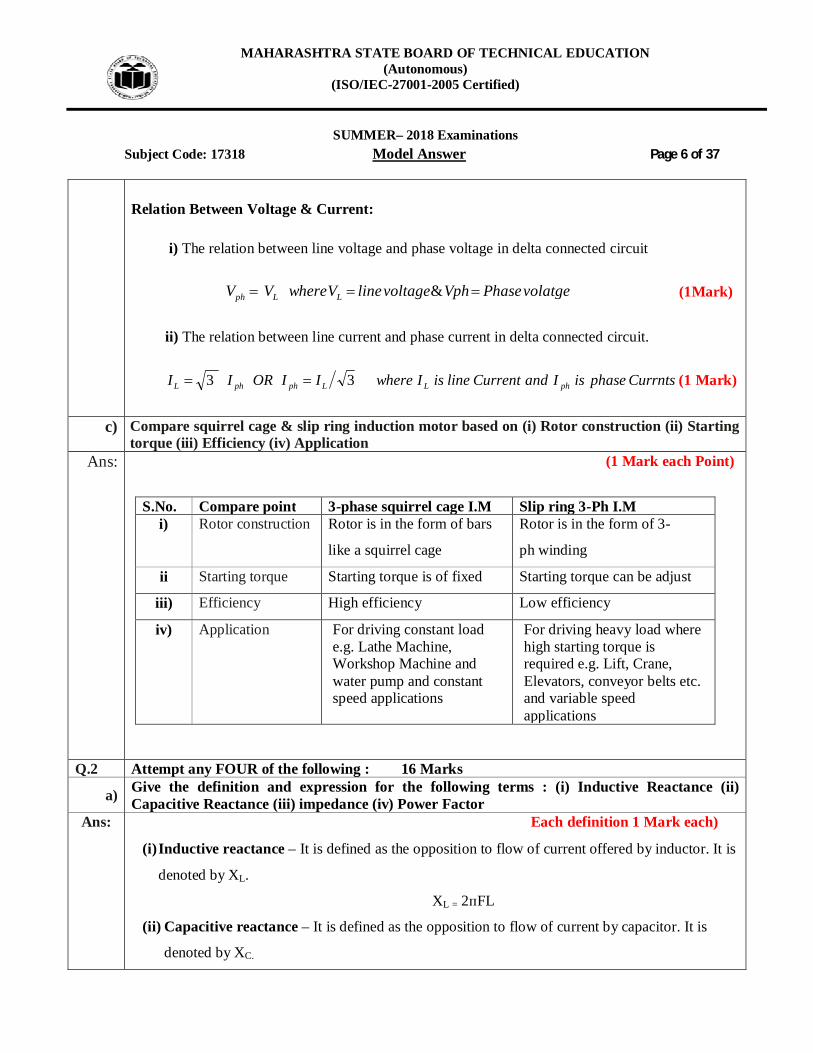
c) Compare squirrel cage & slip ring induction motor based on (i) Rotor construction (ii) Starting
torque (iii) Efficiency (iv) Application Ans: (1 Mark each Point)
S.No. Compare point 3-phase squirrel cage I.M Slip ring 3-Ph I.M
i) Rotor construction Rotor is in the form of bars
like a squirrel cage
Rotor is in the form of 3-
ph winding
ii Starting torque Starting torque is of fixed Starting torque can be adjust
iii) Efficiency High efficiency Low efficiency
iv) Application For driving constant load e.g. Lathe Machine, Workshop Machine and water pump and constant speed applications
For driving heavy load where high starting torque is required e.g. Lift, Crane, Elevators, conveyor belts etc. and variable speed applications
Q.2 Attempt any FOUR of the following : 16 Marks
a) Give the definition and expression for the following terms : (i) Inductive Reactance (ii) Capacitive Reactance (iii) impedance (iv) Power Factor
Ans: Each definition 1 Mark each)
(i) Inductive reactance – It is defined as the opposition to flow of current offered by inductor. It is
denoted by XL.
XL = 2ᴨFL
(ii) Capacitive reactance – It is defined as the opposition to flow of current by capacitor. It is
denoted by XC.

MAHARASHTRA STATE BOARD OF TECHNICAL EDUCATION (Autonomous)
(ISO/IEC-27001-2005 Certified)
SUMMER– 2018 Examinations
Subject Code: 17318 Model Answer Page 7 of 37
XC = 1∕2ᴨFC
(iii) Impedance - It is defined as the total opposition to flow of current present in the circuit. It is
denoted by Z.
Z = R+jXL - - - -(For inductive reactance)
Z = R+jXC - - - - (For capacitive reactance)
(iv) Power factor – It is the cosine of angle between voltage and current.
Power factor = cosØ RCosZ
b) Explain the phenomenon of resonance in RLC series circuit. Ans: Explanation of resonance in R-L-C series circuit : ( 4 Marks)
The resonance of a series RLC circuit occurs when the inductive and capacitive reactances are equal in magnitude.
OR Resonance is the phenomenon in AC circuit in which circuit exhibits unity power factor or applied voltage and resulting current are in phase with each other.
Under series resonance condition XL=XC, Power factor is unity or 1 i.e. cosΦ =1 Impedance (Z) = resistance (R) Current is maximum
OR 1. Condition for resonance: ( 2 Mark)
In a series RLC circuit the Series Resonance occurs at point were the inductive
reactance of the inductor becomes equal in value to the capacitive reactance of the capacitor. In
other words, XL = XC.
2. Value of current during series resonance. ( 1 Mark)
Current during series resonance is maximum as value of impedance is equal to resistance in
MAHARASHTRA STATE BOARD OF TECHNICAL EDUCATION (Autonomous)
(ISO/IEC-27001-2005 Certified)
SUMMER– 2018 Examinations
Subject Code: 17318 Model Answer Page 8 of 37
the circuit.
3. Graphical representation of current: ( 1 Mark)
or equivalent circuit
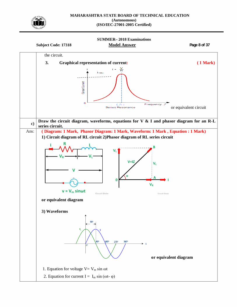
c) Draw the circuit diagram, waveforms, equations for V & I and phasor diagram for an R-L series circuit.
Ans: ( Diagram: 1 Mark, Phasor Diagram: 1 Mark, Waveform: 1 Mark , Equation : 1 Mark) 1) Circuit diagram of RL circuit 2)Phasor diagram of RL series circuit
or equivalent diagram 3) Waveforms
or equivalent diagram
1. Equation for voltage V= Vm sin ωt
2. Equation for current I = Im sin (ωt- φ)

MAHARASHTRA STATE BOARD OF TECHNICAL EDUCATION (Autonomous)
(ISO/IEC-27001-2005 Certified)
SUMMER– 2018 Examinations
Subject Code: 17318 Model Answer Page 9 of 37
d) State different types of power in AC circuits. Write its expression and unit. Ans: Different types of power in A.C circuit:
i) Active Power (P):- ( 1.5 Mark)
The active power is defined as the average power Pavg taken by or consumed by the given circuit.
CosIVP .. Unit: - Watt OR Kilowatt
ii) Reactive Power (Q):- ( 1.5 Mark)
The reactive power is defined as the product of V, I and sine of angle between V and I i.e. Q= V.I. sin Units: - VAR ORKVAR iii) Apparent Power (S): ( 1 Mark)
2 2KVA KW KVAR
Unit: volt-ampere (VA) or kilo-volt-ampere (kVA) or Mega-volt-ampere (MVA)
S=VI=I2Z volt-amp
OR
Equation For three phase:-
1. Active Power P = √3 VL IL Cos Φ (Watt or Kilo watt) (1/2 Mark)
2. Reactive Power Q = √3VL IL Sin Φ (VAR or kVAR) (1/2 Mark )
3. Apparent Power S = √3VL IL ( VA or kVA) (1/2 Mark )
Equation For Single phase:-
1. Active Power P = V I Cos Φ (Watt or Kilo watt) (1/2 Mark)
2. Reactive Power Q = V I Sin Φ (VAR or kVAR) (1/2 Mark)
3. Apparent Power S = V I ( VA or kVA) (1/2 Mark)
Relation between power
(1 Mark)

MAHARASHTRA STATE BOARD OF TECHNICAL EDUCATION (Autonomous)
(ISO/IEC-27001-2005 Certified)
SUMMER– 2018 Examinations
Subject Code: 17318 Model Answer Page 10 of 37
e) State and explain the principle of 3-Ph. emf generation. Draw its waveform. Ans: 3-Ph. emf generation : (Figure -2 Marks & Explanations- 2 Marks)
OR
In a three – phase a.c. generator three coils are fastened rigidly together and displaced from each other by 1200. It is made to rotate about a fixed axis in a uniform magnetic field. Each coil is provided with a separate set of slip rings and brushes.
An emf is induced in each of the coils with a phase difference of 120o. Three coils a1 a2, b1b2 and c1 c2 are mounted on the same axis but displaced from each other by 1200, and the coils rotate in the anticlockwise direction in a magnetic field (Fig: a).

MAHARASHTRA STATE BOARD OF TECHNICAL EDUCATION (Autonomous)
(ISO/IEC-27001-2005 Certified)
SUMMER– 2018 Examinations
Subject Code: 17318 Model Answer Page 11 of 37
Fig; a Section of 3 phase ac generator
When the coil a1 a2 is in position AB, emf induced in this coil is zero and starts increasing in the positive direction. At the same instant the coil b1b2 is 120o behind coil a1a2, so that emf induced in this coil is approaching its maximum negative value and the coil c1 c2 is 2400behind the coil a1 a2, so the emf induced in this coil has passed its positive maximum value and is decreasing.
Fig: b Three phase emf
Thus the emfs induced in all the three coils are equal in magnitude and of same frequency. The emfs induced in the three coils are;
ea1a2 = E0 sin ωt
eb1b2 = E0 sin (ωt – 2π/3)
ec1c2 = E0 sin (ωt – 4π/3)
The emfs induced and phase difference in the three coils a1 a1, b1 b1 and c1 c1 are shown in Fig: b &Fig:c.

MAHARASHTRA STATE BOARD OF TECHNICAL EDUCATION (Autonomous)
(ISO/IEC-27001-2005 Certified)
SUMMER– 2018 Examinations
Subject Code: 17318 Model Answer Page 12 of 37
Fig: c Angular displacement between the armature
f) Compare autotransformer & two winding transformer. (any 4)
Ans: (Any four points expected: Each point 1 Mark)
S.No. Points Autotransformer Two winding transformer 1. Symbol
2. Number of
windings
It has one winding It has two windings
3. Copper saving Copper saving takes more as
compared to two winding
Copper saving is less
4. Size Size is small Size is large
5 cost Cost is low Cost is high
6 Losses in winding Less losses takes place More losses takes place
7. Efficiency Efficiency is low Efficiency is high
8. Electrical isolation There is no electrical isolation Electrical isolation is present
in between primary and
secondary winding
9. Movable contact Movable contact is present Movable contact is not present
11. Application Variac, starting of ac motors,
dimmerstat.
Mains transformer, power
supply, welding, isolation
transformer

MAHARASHTRA STATE BOARD OF TECHNICAL EDUCATION (Autonomous)
(ISO/IEC-27001-2005 Certified)
SUMMER– 2018 Examinations
Subject Code: 17318 Model Answer Page 13 of 37
Q.3 Attempt any FOUR of the following : 16 Marks a) Compare dc supply with ac supply.
Ans: Differentiate DC supply with AC supply: ( Any Four Point Expected : 1 Mark each)
S.No. Points DC Supply AC Supply 1. Wave form
2 Cause of the direction of flow of electrons
Steady magnetism along the wire
Rotating magnet along the wire
3 Frequency The frequency of direct current is zero.
The frequency of alternating current is 50Hz or 60Hz depending upon the country.
4 Direction It flows in one direction in the circuit.
It reverses its direction while flowing in a circuit.
5 Current It is the current of constant magnitude.
It is the current of magnitude varying with time
6 Flow of Electrons Electrons move steadily in one direction or 'forward'.
Electrons keep switching directions - forward and backward.
7 Obtained from Cell or Battery or D.C. generator
A.C Generator and mains.
8 Passive Parameters Resistance only Impedance.
b) Define leading and lagging ac quantities. Draw waveform representation and equations representing the same.
Ans: (Meaning - 2 Marks , Waveforms representation & Equation -2 Marks)
i) Leading AC Quantities: Whenever there is a positive phase difference between AC waveform and reference
waveform then the AC waveform is leading with respect to reference. ii) Lagging AC Quantities:
Whenever there is a negative phase difference between AC waveform and reference
waveform then the AC waveform is lagging with respect to reference.

MAHARASHTRA STATE BOARD OF TECHNICAL EDUCATION (Autonomous)
(ISO/IEC-27001-2005 Certified)
SUMMER– 2018 Examinations
Subject Code: 17318 Model Answer Page 14 of 37
iii) Leading Phase difference waveform: ii)Lagging Phase difference waveform
OR equivalent figure
Leading Lagging
1. Equation for voltage V= Vm sin ωt1. Equation for voltage V= Vm sin ωt
2. Equation for current I = Im sin (ωt + φ)2. Equation for current I = Im sin (ωt - φ)
c) A choke coil is connected across 230 V, 50 Hz supply. The power consumed by the coil is 960 W and current Irms is 8A. Calculate the circuit constants R & L.
Ans: Given Data:
I = 8 A, V = 230V, f = 50 Hz, and P = 960 watt
i) Power Factor :
CosIVP -------------------------------------------------------------------------- (1/2 Mark)
-------------------------------------------------------------------------- (1/2 Mark) ii) Impedance Z :
- ---------------------------------------------(1/2 Mark)
--------------------------------------------------- (1/2 Mark) iii) Resistance R :
88.88540.0 ZCosRZRCos ---------------------------------- (1/2 Mark)
R=14.95 Ω------------------------------------------ (1/2 Mark)

MAHARASHTRA STATE BOARD OF TECHNICAL EDUCATION (Autonomous)
(ISO/IEC-27001-2005 Certified)
SUMMER– 2018 Examinations
Subject Code: 17318 Model Answer Page 15 of 37 iv) Inductance L :
222 RZX L - -------------------------- (1/2 Mark)
22 RZX L
L=0.0781 H--------------------------------------------------------------- (1/2 Mark)
d) Compare magnetic circuits with electric circuits. Ans: Compare Magnetic and Electric circuit: ( Any Four Point expected : 1 Mark each)
S.No Magnetic circuit Electric circuit
1 The magnetic circuit in which magnetic flux flow
Path traced by the current is known as electric current.
2 MMF is the driving force in the magnetic circuit. The unit is ampere turns.
EMF is the driving force in the electric circuit. The unit is Volts.
3 There is flux φ in the magnetic circuit which is measured in the weber.
There is a current I in the electric circuit which is measured in amperes.
4 The number of magnetic lines of force decides the flux.
The flow of electrons decides the current in conductor.
5 Reluctance (S) is opposed by magnetic path to the flux. The Unit is ampere turn/weber.
Resistance (R) oppose the flow of the current. The unit is Ohm
6 S = l/ (µ0µra). Directly proportional to l. Inversely proportional to µ = µ0µr. Inversely proportional to a
R = ρ. l/a. Directly proportional to l. Inversely proportional to a. Depends on nature of material.
7 The Flux = MMF/ Reluctance The current I = EMF/ Resistance
8 The flux density The current density
9 Kirchhoff mmf law and flux law is applicable to the magnetic flux.
Kirchhoff current law and voltage law is applicable to the electric circuit.
MAHARASHTRA STATE BOARD OF TECHNICAL EDUCATION (Autonomous)
(ISO/IEC-27001-2005 Certified)
SUMMER– 2018 Examinations
Subject Code: 17318 Model Answer Page 16 of 37
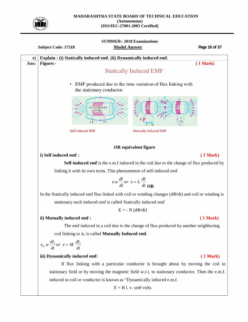
e) Explain : (i) Statically induced emf. (ii) Dynamically induced emf. Ans: Figure:- ( 1 Mark)
OR equivalent figure
i) Self induced emf : ( 1 Mark)
Self-induced emf is the e.m.f induced in the coil due to the change of flux produced by
linking it with its own turns. This phenomenon of self-induced emf
dI dIe or e Ldt dt
OR
In the Statically induced emf flux linked with coil or winding changes (dΦ/dt) and coil or winding is
stationary such induced emf is called Statically induced emf
E = - N (dΦ/dt)
ii) Mutually induced emf : ( 1 Mark)
The emf induced in a coil due to the change of flux produced by another neighboring
coil linking to it, is called Mutually Induced emf.
1 1m
dI dIe or e Mdt dt
iii) Dynamically induced emf: ( 1 Mark)
If flux linking with a particular conductor is brought about by moving the coil in
stationary field or by moving the magnetic field w.r.t. to stationary conductor. Then the e.m.f.
induced in coil or conductor is known as “Dynamically induced e.m.f.
E = B l. v. sinθ volts
MAHARASHTRA STATE BOARD OF TECHNICAL EDUCATION (Autonomous)
(ISO/IEC-27001-2005 Certified)
SUMMER– 2018 Examinations
Subject Code: 17318 Model Answer Page 17 of 37
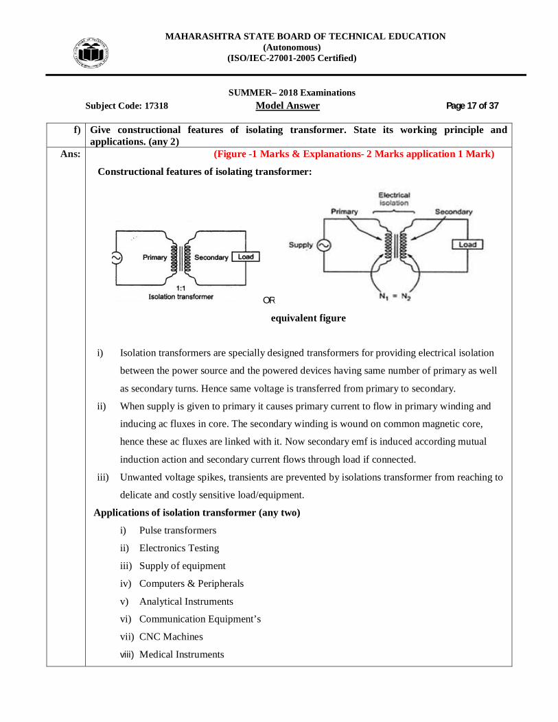
f) Give constructional features of isolating transformer. State its working principle and applications. (any 2)
Ans: (Figure -1 Marks & Explanations- 2 Marks application 1 Mark)
Constructional features of isolating transformer:
OR
equivalent figure
i) Isolation transformers are specially designed transformers for providing electrical isolation
between the power source and the powered devices having same number of primary as well
as secondary turns. Hence same voltage is transferred from primary to secondary.
ii) When supply is given to primary it causes primary current to flow in primary winding and
inducing ac fluxes in core. The secondary winding is wound on common magnetic core,
hence these ac fluxes are linked with it. Now secondary emf is induced according mutual
induction action and secondary current flows through load if connected.
iii) Unwanted voltage spikes, transients are prevented by isolations transformer from reaching to
delicate and costly sensitive load/equipment.
Applications of isolation transformer (any two)
i) Pulse transformers
ii) Electronics Testing
iii) Supply of equipment
iv) Computers & Peripherals
v) Analytical Instruments
vi) Communication Equipment’s
vii) CNC Machines
viii) Medical Instruments

MAHARASHTRA STATE BOARD OF TECHNICAL EDUCATION (Autonomous)
(ISO/IEC-27001-2005 Certified)
SUMMER– 2018 Examinations
Subject Code: 17318 Model Answer Page 18 of 37
Q.4 Attempt any FOUR of the following : 16 Marks
a) A coil of resistance 10 ohm and 0.1 H is connected in series with a capacitance of 150 µF across 230 V, 50 Hz ac supply. Calculate impedance, current, power factor and power consumed by the circuit.
Ans: I= V/Z
i) XL = XL=2πfL = 2π×50×0.1 XL= 31.4 Ω
ii) XC =
XC=Cf2
1
6
12 50 150 10
iii) Impedance Z =
22 )()(Im XcXRZpedance l ------------------------------------------- (1/2 Mark)
---- ---------------------------------------------------------------- (1/2 Mark)
iv) To Find Current=
---------- ------------------------------------------------------------------ (1/2 Mark)
I=16.12 Amp - --------------------------------------------------------------- (1/2 Mark)
iii) power factor
------------------------------------------------------------------------------ (1/2 Mark)
----------------------------------------------------------------- (1/2 Mark)
Power Consumed P :
CosIVP ------------------------------------------------------------------- (1/2 Mark)
- -------------------------------------- (1/2 Mark)
MAHARASHTRA STATE BOARD OF TECHNICAL EDUCATION (Autonomous)
(ISO/IEC-27001-2005 Certified)
SUMMER– 2018 Examinations
Subject Code: 17318 Model Answer Page 19 of 37
b) State the emf equation of a single phase transformer. Define (i) Current Ratio (ii) Transformation Ratio (iii) Voltage Ratio
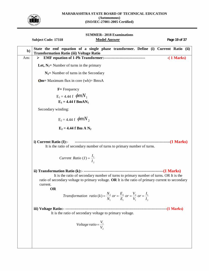
Ans: EMF equation of 1-Ph Transformer:-------------------------------- -( 1 Marks)
Let, N1= Number of turns in the primary
N2= Number of turns in the Secondary
m= Maximum flux in core (wb)= BmxA
F= Frequency
E1 = 4.44 f 1mN E1 = 4.44 f BmAN1
Secondary winding:
E2 = 4.44 f 2mN
E2 = 4.44 f Bm A N2 i) Current Ratio (I):- --------------------------------------------------------------------------(1 Marks) It is the ratio of secondary number of turns to primary number of turns.
2
1)(IIIRatioCurrent
ii) Transformation Ratio (k):- --------------------------------------------------------------(1 Marks)
It is the ratio of secondary number of turns to primary number of turns. OR It is the ratio of secondary voltage to primary voltage. OR It is the ratio of primary current to secondary current.
OR
2
1
1
2
1
2
1
2)(IIor
VVor
EEor
NNkratiotionTransforma
iii) Voltage Ratio:- -------------------------------------------------------------------------------(1 Marks) It is the ratio of secondary voltage to primary voltage.
2
1
VVratioVoltage
MAHARASHTRA STATE BOARD OF TECHNICAL EDUCATION (Autonomous)
(ISO/IEC-27001-2005 Certified)
SUMMER– 2018 Examinations
Subject Code: 17318 Model Answer Page 20 of 37
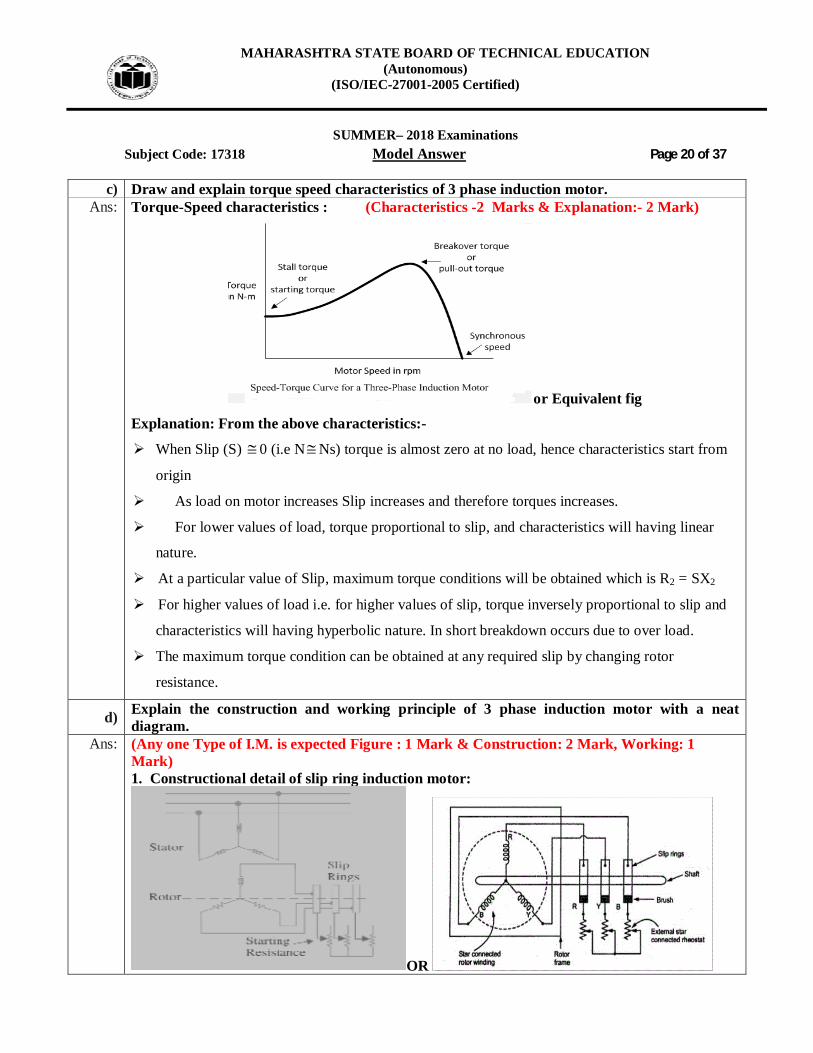
c) Draw and explain torque speed characteristics of 3 phase induction motor. Ans: Torque-Speed characteristics : (Characteristics -2 Marks & Explanation:- 2 Mark)
or Equivalent fig
Explanation: From the above characteristics:-
When Slip (S) 0 (i.e NNs) torque is almost zero at no load, hence characteristics start from
origin
As load on motor increases Slip increases and therefore torques increases.
For lower values of load, torque proportional to slip, and characteristics will having linear
nature.
At a particular value of Slip, maximum torque conditions will be obtained which is R2 = SX2
For higher values of load i.e. for higher values of slip, torque inversely proportional to slip and
characteristics will having hyperbolic nature. In short breakdown occurs due to over load.
The maximum torque condition can be obtained at any required slip by changing rotor
resistance.
d) Explain the construction and working principle of 3 phase induction motor with a neat diagram.
Ans: (Any one Type of I.M. is expected Figure : 1 Mark & Construction: 2 Mark, Working: 1 Mark) 1. Constructional detail of slip ring induction motor:
OR

MAHARASHTRA STATE BOARD OF TECHNICAL EDUCATION (Autonomous)
(ISO/IEC-27001-2005 Certified)
SUMMER– 2018 Examinations
Subject Code: 17318 Model Answer Page 21 of 37 Explanation: It consist laminated cylindrical core and it carries three phase windings.
The rotor winding may be single layer or double layer.
The rotor winding is uniformly distributed in slots and it is always star connected.
Rotor is wound for same number of poles as that of the stator winding.
Three phases of rotor winding is are shorted internally to form star point and other three
winding terminals are brought out and joined to three insulated slip rings mounted on the
rotor shaft.
One brush is resting on each slip ring. These three brushes are further externally connected to
three phase star connected rheostat.
OR
2. Constructional detail of Squirrel cage induction motor:
or or equivalent figure
Explanation: It consist laminated cylindrical core having slots on its outer periphery.
One copper or aluminum bar is placed in each slot. All the bars are joined at each end by
metal rings called end rings.
Rotor bars are brazed or electrically welded or bolted to the end rings.
This form permanently short circuited winding which is non breakable.
The rotor slots are not parallel to the shaft but they are skewed at certain angle with the shaft.

MAHARASHTRA STATE BOARD OF TECHNICAL EDUCATION (Autonomous)
(ISO/IEC-27001-2005 Certified)
SUMMER– 2018 Examinations
Subject Code: 17318 Model Answer Page 22 of 37
Working principle of 3-phase induction motor:
When 3-phase stator winding is energized from a 3-phase supply, a rotating magnetic field is
set up in air gap which rotates round the stator at synchronous speed Ns (= 120 f/P).
The rotating field passes through the air gap and cuts the rotor conductors, which as yet, are
stationary.
Due to the relative speed between the rotating flux and the stationary rotor, e.m.f. are
induced in the rotor conductors.
Since the rotor circuit is short-circuited, currents start flowing in the rotor conductors.
The current-carrying rotor conductors are placed in the magnetic field produced by the stator.
Consequently, mechanical force acts on the rotor conductors.
The sum of the mechanical forces on all the rotor conductors produces a torque which tends
to move the rotor.
In the same direction as the rotating field according to Lenz’s law.
e) Draw schematic representation and explain the principle of working of split phase single phase induction motor.
Ans: Circuit diagram of resistance split single phase induction motor: ( Figure : 2 Marks & Working : 2 Marks)
or equivalent figure
Working of resistors split single phase induction motor:
To make a single phase induction motor self-starting, we should somehow produce
a rotating magnetic field. This may be achieved by converting a single-phase supply into
two-phase supply through the use of an additional winding. In a split phase induction motor,
the additional winding is known as auxiliary winding or starting winding.
Because of the high value of resistance in the starting winding, a phase shift of 30 to 400 is
MAHARASHTRA STATE BOARD OF TECHNICAL EDUCATION (Autonomous)
(ISO/IEC-27001-2005 Certified)
SUMMER– 2018 Examinations
Subject Code: 17318 Model Answer Page 23 of 37
introduced in the current carried by starting and running windings. This creates rotating
magnetic field and the motor starts running.
A centrifugal switch S is connected in series with the starting winding
It function is to automatically disconnected the starting winding from the supply when the
motor has reached 70 to 80 per cent of its full load speed.
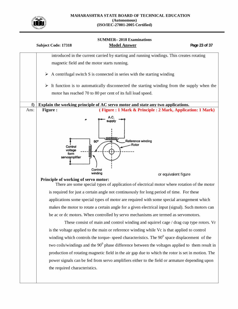
f) Explain the working principle of AC servo motor and state any two applications. Ans: Figure : ( Figure : 1 Mark & Principle : 2 Mark, Application: 1 Mark)
or equivalent figure Principle of working of servo motor:
There are some special types of application of electrical motor where rotation of the motor
is required for just a certain angle not continuously for long period of time. For these
applications some special types of motor are required with some special arrangement which
makes the motor to rotate a certain angle for a given electrical input (signal). Such motors can
be ac or dc motors. When controlled by servo mechanisms are termed as servomotors.
These consist of main and control winding and squirrel cage / drag cup type rotors. Vr
is the voltage applied to the main or reference winding while Vc is that applied to control
winding which controls the torque- speed characteristics. The 900 space displacement of the
two coils/windings and the 900 phase difference between the voltages applied to them result in
production of rotating magnetic field in the air gap due to which the rotor is set in motion. The
power signals can be fed from servo amplifiers either to the field or armature depending upon
the required characteristics.

MAHARASHTRA STATE BOARD OF TECHNICAL EDUCATION (Autonomous)
(ISO/IEC-27001-2005 Certified)
SUMMER– 2018 Examinations
Subject Code: 17318 Model Answer Page 24 of 37
Application of AC Servomotor: ( Any Two Application expected) 1. Robotics 2. Conveyor Belts 3. Camera Auto Focus 4. Robotic Vehicle 5. Solar Tracking System 6. Metal Cutting & Metal Forming Machines 7. Antenna Positioning 8. Woodworking/CNC 9. Textiles 10. Printing Presses/Printers 11. Automatic Door Opener
Q.5 Attempt any FOUR of the following : 16 Marks
a) An alternating current is given by i = 10 sin 628 t. Calculate (i) Average value (ii) RMS value (iii) Frequency (iv) Time period
Ans: Given data : i = 10 sin 628t -------------i
Step-I:- Average value of current:
Step-II:- To find RMS value of Current:
Step-III:- To find frequency:
Step-III:- To find time Period
MAHARASHTRA STATE BOARD OF TECHNICAL EDUCATION (Autonomous)
(ISO/IEC-27001-2005 Certified)
SUMMER– 2018 Examinations
Subject Code: 17318 Model Answer Page 25 of 37
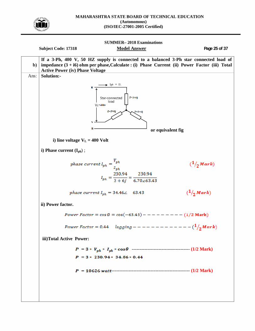
b) If a 3-Ph, 400 V, 50 HZ supply is connected to a balanced 3-Ph star connected load of impedance (3 + i6) ohm per phase,Calculate : (i) Phase Current (ii) Power Factor (iii) Total Active Power (iv) Phase Voltage
Ans: Solution:-
or equivalent fig
i) line voltage VL = 400 Volt
i) Phase current (Iph) ;
ii) Power factor.
iii)Total Active Power:
------------------------------------- (1/2 Mark)
-------------------------------------------------- (1/2 Mark)
MAHARASHTRA STATE BOARD OF TECHNICAL EDUCATION (Autonomous)
(ISO/IEC-27001-2005 Certified)
SUMMER– 2018 Examinations
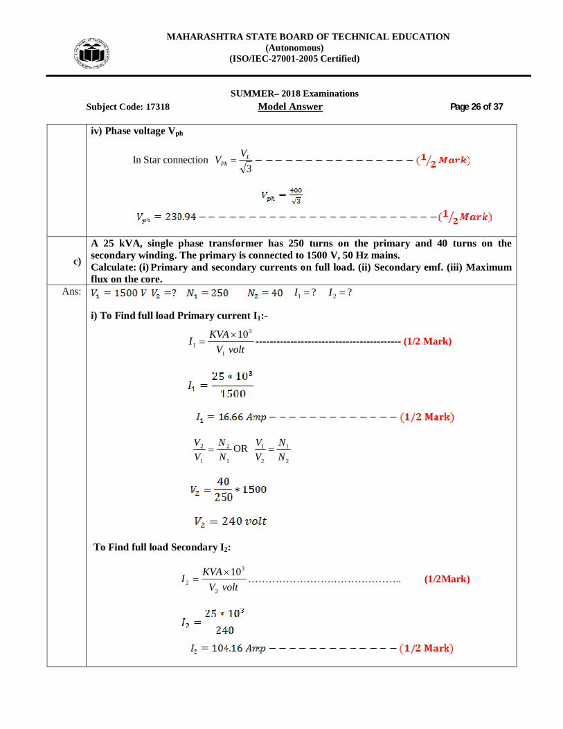
Subject Code: 17318 Model Answer Page 26 of 37 iv) Phase voltage Vph
In Star connection 3L
PhVV
c)
A 25 kVA, single phase transformer has 250 turns on the primary and 40 turns on the secondary winding. The primary is connected to 1500 V, 50 Hz mains. Calculate: (i) Primary and secondary currents on full load. (ii) Secondary emf. (iii) Maximum flux on the core.
Ans: ?? 21 II
i) To Find full load Primary current I1:-
voltV
KVAI1
3
110
------------------------------------------ (1/2 Mark)
1
2
1
2
NN
VV
OR 2
1
2
1
NN
VV
To Find full load Secondary I2:
voltV
KVAI2
3
210
…………………….……………….. (1/2Mark)

MAHARASHTRA STATE BOARD OF TECHNICAL EDUCATION (Autonomous)
(ISO/IEC-27001-2005 Certified)
SUMMER– 2018 Examinations
Subject Code: 17318 Model Answer Page 27 of 37 iii) Maximum flux:
11 44.4 NfE m ------------------------------------------------------------- (1/2 Mark)
1
1
44.4 NfE
m
iv) Secondary emf
E2 = 4.44 f 2mN
d) State the necessity of starter in case of three phase induction motor and explain. Ans: Necessity of the starter in 3 phase I.M :-------------------------------------------------- (4 Mark)
At the time of starting, slip s= 1, so the rotor resistance which depends on slip
i.e. R2(1-S)/S will be equal to "0",
i.e. rotor will act as short circuit.
Hence initially induction motor will draw heavy amount of current. Thus, a starter is needed in
order to limit the starting current.
After the motor has started at reduced starting current and hence reduced voltage, the connections
are diverted towards the mains supply so that now, the motor can run at higher starting current and
voltage.
e) Explain any one method of speed control of single phase induction motor. Ans: ( List : 2 Marks & 2 Marks for any one method explanation)
Following methods to control the speed of 3 phase induction motor: (Explanation of any one
method is expected)
1) By Varying applied frequency (Frequency control) 2) By varying applied voltage (Stator voltage control) 3) By varying number of poles of the stator winding (Pole Changing)

MAHARASHTRA STATE BOARD OF TECHNICAL EDUCATION (Autonomous)
(ISO/IEC-27001-2005 Certified)
SUMMER– 2018 Examinations
Subject Code: 17318 Model Answer Page 28 of 37
4) By Voltage/ frequency control (V/f) method 5) PWM method
1. by varying applied Frequency (Frequency control):
The synchronous speed of an induction motor is given by P
fNS
120 .
It is clear from the equation that the speed of the induction motor can be changed by changing the frequency of the supply.
The speed of the motor will increase if frequency increases and vice versa. Changing the frequency of supply to the motor is difficult. Therefore this method is
only employed where the variable frequency alternator is available for the above purpose.
2. By varying applied voltage ( Stator voltage control):
This method is very easy but rarely used in commercial practice because a large variation of voltage produces a very small change in speed and much energy is wasted.
In this method three resistances are inserted in series with the stator winding of the motor and the value of these resistances is varied by a common handle, so that equal resistances come in the stator circuit.
For a particular load when voltage increases, speed of the motor also increases and vice-versa.
3. Pole Changing : a) Speed control using two separate winding-
An induction motor stator is wound for fixed number of poles. The speed of the induction motor depends upon the number of poles for which stator is wound. If instead of one stator winding two independent windings are wound for a different number of poles then two definite speeds can be obtained. e.g. one winding for 4- pole and another winding for 8-poles them speeds can be achieved. Two windings are insulated from one another when any one of the winding is used, the other should be kept open circuited by the switch or kept star

MAHARASHTRA STATE BOARD OF TECHNICAL EDUCATION (Autonomous)
(ISO/IEC-27001-2005 Certified)
SUMMER– 2018 Examinations
Subject Code: 17318 Model Answer Page 29 of 37
connected.
PfN S
120
b) Speed control using consequent pole technique-
Fig (a) Fig (b)
This method is used for obtaining multispeed in squirrel cage induction motor. In this method only one winding is used and it is provided with some simple switching means (device), so that connections of coils with supply are changed and different number of poles is formed. This is explained as below-
Above fig (a) shows developed winding diagram for one phase of balanced three phase winding.
Coil-1 & c oil-3 are in series and they form one coil group while coil-2 & coil-4 connected in series to form another coil group. These two coil groups are connected in series such that all coils are magnetized in the same direction.
Hence these coils form 4-North poles and 4-South poles. Thus this arrangement gives total 8-poles.
If two coil groups are connected in series as shown in fig (b), there will be only 4- poles formed. Thus synchronous speed in this case will be doubled than first case.
4. By Voltage/ frequency control (V/f) method:

MAHARASHTRA STATE BOARD OF TECHNICAL EDUCATION (Autonomous)
(ISO/IEC-27001-2005 Certified)
SUMMER– 2018 Examinations
Subject Code: 17318 Model Answer Page 30 of 37
If the ratio of voltage to frequency is kept constant, the flux remains constant. The maximum torque which is independent of frequency can be maintained
approximately constant. However at a low frequency, the air gap flux is reduced due to drop in the stator
impedance and the voltage has to be increased to maintain the torque level. This type of control is usually known as Volts/ Hertz or V/f control. A simple circuit arrangement for obtaining variable voltage and frequency is as shown
in the above figure.
f) Give any two applications for each, (i) Universal Motor (ii) Stepper Motor (iii) Servo Motor (iv) Split Phase Induction Motor.
Ans: i) Application of Universal Motor : ( Any Two application expected : 1 Mark each)
1) Mixer
2) Food processor
3) Heavy duty machine tools
4) Grinder
5) Vacuum cleaners
6) Refrigerators
7) Driving sewing machines
8) Electric Shavers
9) Hair dryers
10) Small Fans
11) Cloth washing machine
12) portable tools like blowers, drilling machine, polishers etc
ii) Applications of stepper motor- (Two application expected-1 Mark)
1.Suitable for use with computer controlled system
2. Widely used in numerical control of machine tools.
3. Tape drives
4. Floppy disc drives
5. Computer printers
6. X-Y plotters

MAHARASHTRA STATE BOARD OF TECHNICAL EDUCATION (Autonomous)
(ISO/IEC-27001-2005 Certified)
SUMMER– 2018 Examinations
Subject Code: 17318 Model Answer Page 31 of 37
7. Robotics
8. Textile industries
9. Integrated circuit fabrication
10. Electric watches
11. In space craft's launched for scientific explorations of planets.
12. In the production of science friction movies
13 Automotive
14. Food processing 15. Packaging iii) Applications of servo motor : ( Any Two expected: 1 Mark each)
1. Robotics
2. Conveyor Belts
3. Camera Auto Focus
4. Robotic Vehicle
5. Solar Tracking System
6. Metal Cutting & Metal Forming Machines
7. Antenna Positioning
8. Woodworking/CNC
9. Textiles
10. Printing Presses/Printers
11. Automatic Door Openers
iii) Applications of Split Phase Induction Motor : ( Any Two expected: 1 Mark each)
1. washing machine 2. Air conditioning fans. 3. Mixer grinder 4. floor polishers. 5. Blowers 6. Centrifugal pumps 7. Drilling and lathe machine.

MAHARASHTRA STATE BOARD OF TECHNICAL EDUCATION (Autonomous)
(ISO/IEC-27001-2005 Certified)
SUMMER– 2018 Examinations
Subject Code: 17318 Model Answer Page 32 of 37
Q.6 Attempt any FOUR of the following : 16 Marks
a) Three impedances each of 3 ohm resistance and 5 ohm reactance in series are connected in delta across 50 Hz, 440 V line voltage. Find,(i) Impedance (ii) Phase current (iii) Power factor (iv) Total power
Ans:
or equivalent fig
ohmX L 5
i) Impedance =
22 )()(Im LXRZpedance -------------------------------------------- (1/2 Mark)
22 )5()3(Im Zpedance
ii) Phase current :
In case of delta connection phase voltage is equal to line voltage
iii) Power factor.
MAHARASHTRA STATE BOARD OF TECHNICAL EDUCATION (Autonomous)
(ISO/IEC-27001-2005 Certified)
SUMMER– 2018 Examinations
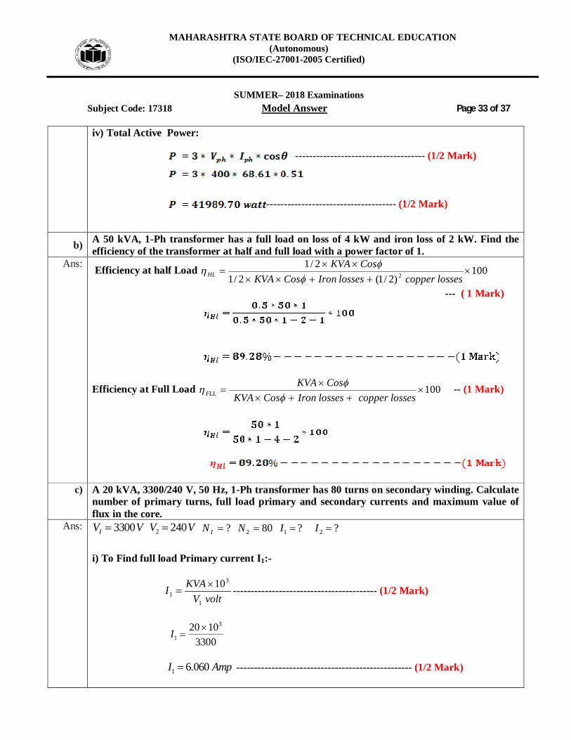
Subject Code: 17318 Model Answer Page 33 of 37 iv) Total Active Power:
------------------------------------- (1/2 Mark)
------------------------------------- (1/2 Mark)
b) A 50 kVA, 1-Ph transformer has a full load on loss of 4 kW and iron loss of 2 kW. Find the efficiency of the transformer at half and full load with a power factor of 1.
Ans: Efficiency at half Load 100)2/1(2/1
2/12
lossescopperlossesIronCosKVA
CosKVAHL
--- ( 1 Mark)
Efficiency at Full Load 100
lossescopperlossesIronCosKVACosKVA
FLL
-- (1 Mark)
c) A 20 kVA, 3300/240 V, 50 Hz, 1-Ph transformer has 80 turns on secondary winding. Calculate number of primary turns, full load primary and secondary currents and maximum value of flux in the core.
Ans: 3300IV V 2 240V V ?IN 802 N ?? 21 II
i) To Find full load Primary current I1:-
voltV
KVAI1
3
110
----------------------------------------- (1/2 Mark)
3
120 10
3300I
1 6.060I Amp -------------------------------------------------- (1/2 Mark)
MAHARASHTRA STATE BOARD OF TECHNICAL EDUCATION (Autonomous)
(ISO/IEC-27001-2005 Certified)
SUMMER– 2018 Examinations
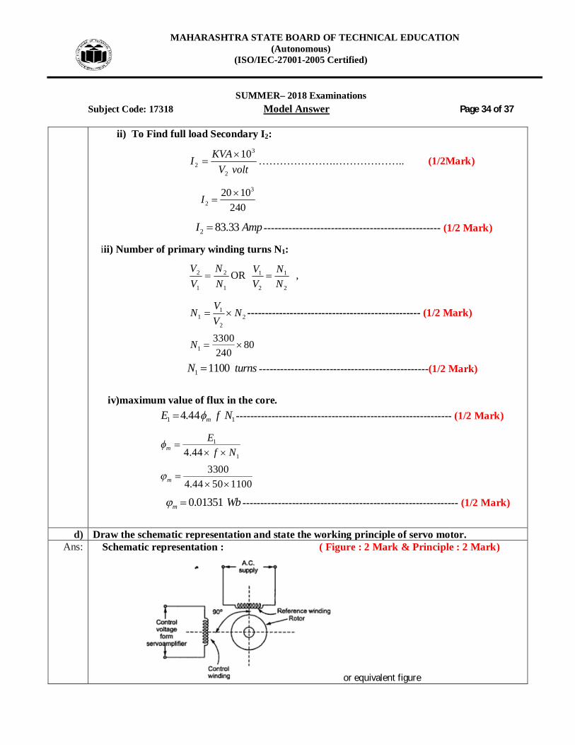
Subject Code: 17318 Model Answer Page 34 of 37 ii) To Find full load Secondary I2:
voltV
KVAI2
3
210
………………….……………….. (1/2Mark)
3
220 10
240I
2 83.33I Amp -------------------------------------------------- (1/2 Mark)
iii) Number of primary winding turns N1:
1
2
1
2
NN
VV
OR 2
1
2
1
NN
VV
,
22
11 N
VVN ------------------------------------------------- (1/2 Mark)
13300 80240
N
1 1100N turns ------------------------------------------------(1/2 Mark) iv)maximum value of flux in the core.
11 44.4 NfE m ------------------------------------------------------------- (1/2 Mark)
1
1
44.4 NfE
m
33004.44 50 1100m
0.01351m Wb ------------------------------------------------------------- (1/2 Mark)
d) Draw the schematic representation and state the working principle of servo motor. Ans: Schematic representation : ( Figure : 2 Mark & Principle : 2 Mark)
or equivalent figure

MAHARASHTRA STATE BOARD OF TECHNICAL EDUCATION (Autonomous)
(ISO/IEC-27001-2005 Certified)
SUMMER– 2018 Examinations
Subject Code: 17318 Model Answer Page 35 of 37
Principle of working of servo motor: There are some special types of application of electrical motor where rotation of the motor
is required for just a certain angle not continuously for long period of time. For these
applications some special types of motor are required with some special arrangement which
makes the motor to rotate a certain angle for a given electrical input (signal). Such motors can
be ac or dc motors. When controlled by servo mechanisms are termed as servomotors.
These consist of main and control winding and squirrel cage / drag cup type rotors. Vr
is the voltage applied to the main or reference winding while Vc is that applied to control
winding which controls the torque- speed characteristics. The 900 space displacement of the
two coils/windings and the 900 phase difference between the voltages applied to them result in
production of rotating magnetic field in the air gap due to which the rotor is set in motion. The
power signals can be fed from servo amplifiers either to the field or armature depending upon
the required characteristics.
e) Explain the principle of operation and reversal of rotation of universal motors. Ans: Figure of Universal motor: ( Figure : 2 Marks & Explanation : 2 Marks)
OR
OR Equivalent figure Working of universal motor: A universal motor works on either DC or single phase AC supply. When the universal
motor is fed with a DC supply, it works as a DC series motor. When current flows in the field
winding, it produces an electromagnetic field. The same current also flows from the armature
conductors. When a current carrying conductor is placed in an electromagnetic field, it
experiences a mechanical force. Due to this mechanical force, or torque, the rotor starts torotate.
The direction of this force is given by Fleming's left hand rule.
MAHARASHTRA STATE BOARD OF TECHNICAL EDUCATION (Autonomous)
(ISO/IEC-27001-2005 Certified)
SUMMER– 2018 Examinations
Subject Code: 17318 Model Answer Page 36 of 37
When fed with AC supply, it still produces unidirectional torque. Because, armature winding
and field winding are connected in series, they are in same phase. Hence, as polarity of AC
changes periodically, the direction of current in armature and field winding reverses at the same
time. Thus, direction of magnetic field and the direction of armature current reverses in such a
way that the direction of force experienced by armature conductors remains same. Thus,
regardless of AC or DC supply, universal motor works on the same principle that DC series
motor works.
Reversal of rotation of universal motors:-
The direction of rotation of a universal motor can be changed by either: (i) Reversing the
field connection with respect to those of armature; or (ii) By using two field windings wound on
the core in opposite directions so that the one connected in series with armature gives clockwise
rotation, while the other in series with the armature gives counterclockwise rotation.
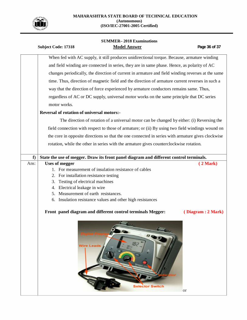
f) State the use of megger. Draw its front panel diagram and different control terminals.
Ans: Uses of megger ( 2 Mark) 1. For measurement of insulation resistance of cables 2. For installation resistance testing 3. Testing of electrical machines 4. Electrical leakage in wire 5. Measurement of earth resistances. 6. Insulation resistance values and other high resistances
Front panel diagram and different control terminals Megger: ( Diagram : 2 Mark)
or

MAHARASHTRA STATE BOARD OF TECHNICAL EDUCATION (Autonomous)
(ISO/IEC-27001-2005 Certified)
SUMMER– 2018 Examinations
Subject Code: 17318 Model Answer Page 37 of 37
or equivalent figure
------------------------------------------------------END-------------------------------------------------------