Embed Size (px)
Citation preview
MAHARASHTRA JEEVAN PRADHIKARAN
(WATER MANAGEMENT)
TENDER NOTICE No.9 FOR 2012-13
[ e.TENDER No. 87 FOR 2012-13 ]
For
AUGMENTATION TO AMBERNATH WATER SUPPLY SCHEME, TAL. AMBERNATH, DIST. THANE
VOLUME - II SPECIFICATIONS
EXECUTIVE ENGINEER M. J. P. W. M. DIVISION
ROAD No.82, SAI SECTION, AMBERNATH (East)
Save Water, every drop counts
MAHARASHTRA JEEVAN PRADHIKARAN
MAHARASHTRA JEEVAN PRADHIKARAN W.M. CIRCLE, PANVEL
MAHARASHTRA JEEVAN PRADHIKARAN
WATER MANAGEMENT DIVISION, AMBERNATH
NAME OF WORK: Augmentation to Ambernath Water Supply Scheme, Tal. Ambernath, Dist. Thane
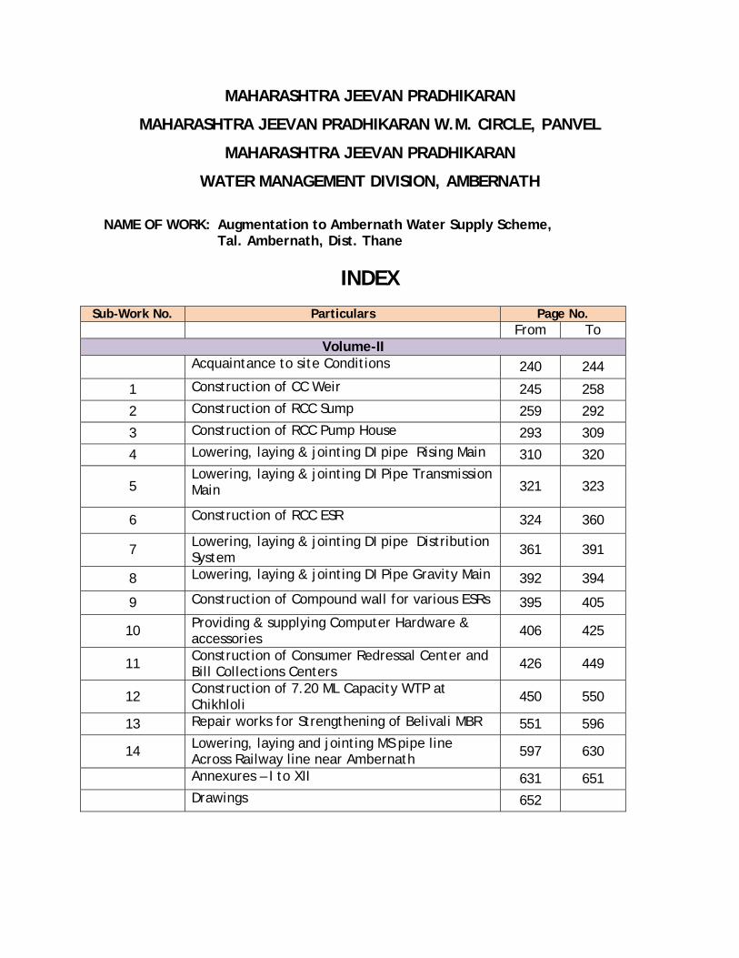
INDEX Sub-Work No. Particulars Page No.
From To Volume-II
Acquaintance to site Conditions 240 244
1 Construction of CC Weir 245 258
2 Construction of RCC Sump 259 292
3 Construction of RCC Pump House 293 309
4 Lowering, laying & jointing DI pipe Rising Main 310 320
5 Lowering, laying & jointing DI Pipe Transmission Main 321 323
6 Construction of RCC ESR 324 360
7 Lowering, laying & jointing DI pipe Distribution System 361 391
8 Lowering, laying & jointing DI Pipe Gravity Main 392 394
9 Construction of Compound wall for various ESRs 395 405
10 Providing & supplying Computer Hardware & accessories 406 425
11 Construction of Consumer Redressal Center and Bill Collections Centers 426 449
12 Construction of 7.20 ML Capacity WTP at Chikhloli 450 550
13 Repair works for Strengthening of Belivali MBR 551 596
14 Lowering, laying and jointing MS pipe line Across Railway line near Ambernath 597 630
Annexures – I to XII 631 651
Drawings 652
240
MAHARASHTRA JEEVAN PRADHIKARAN
MAHARASHTRA JEEVAN PRADHIKARAN W.M. CIRCLE, PANVEL
MAHARASHTRA JEEVAN PRADHIKARAN W.M. DIVISION , AMBERNATH
NAME OF WORK: Augmentation to Ambernath Water Supply Scheme, Tal. Ambernath, Dist. Thane Construction of C.C. weir at Chikhloli Dam, Designing,
constructing & commissioning 7.20 ML capacity WTP at Chikhloli, lowering, laying and jointing D.I.K-7/K-9 pipes for rising main/gravity main/distribution system, construction of R.C.C. sump and pump house, construction of 8 nos. of RCC ESRs at various places with compound wall, construction of Consumer Redressal Centre with computerization, Railway crossing work, Repairs to Belivali MBR etc. complete.
ACQUAINTANCE WITH SITE CONDITIONS AND WORK CONDITIONS
1. The Contractor shall study the site conditions general conditions and data
included in the tender papers and get it verified from actual inspection of
the site etc. before submitting the tender. In case of doubts about any
items or data included in this tender or otherwise, it shall be got clarified
by applying in writing to the Executive Engineer. 05 days in advance
before date of submission of the tender. Once the tender is submitted, it
shall be considered that the Contractor has verified and made himself
conversant with all the details as required for quoting the rates and
completing the work as per tender conditions and specifications.
2. Contractor shall not sell or otherwise dispose off or remove except for
the purpose of this contract, the rubble, stone metal, sand or other
material which may be obtained from any excavation and replaced
material made for the purpose of the contract. All such materials shall be
M.J.P.s property and shall be disposed off in the manner and at place as
may be directed by the Engineer-in-charge in writing and when directed
by him, use any of the materials free of cost.
3. Other unforeseen items to be done in the course of work will have to be
done by the Contractor as per specifications in P.W.D. Hand Book Volume
I and II and will be paid at mutually agreed rates, ISS and standard
241
practice in vogue. Extra charge of claims in respect of extra work shall
not be allowed unless the work to which they relate are in the spirit and
meaning of the specifications or unless such works are ordered in writing
by the Engineer-in- charge and claimed for in the specified manner
before the work is taken in hand.
MATERIAL 4. The Contractor shall make his own arrangements for obtaining rubble,
khandki, headers, metal, sand murum, etc. from private quarry,
Applications of the Contractor for reasonable area of Government land
required for this purpose can be recommended to Revenue Authorities
without any guarantee of making the land for quarry available. All the
materials involved in the construction shall be of best quality and
specifications and shall be got approved from the Engineer in charge
before use. If necessary, materials, shall be got tested from the
Laboratory at his cost. Samples requiring approval shall be submitted by
the Contractor to the Engineer in charge in good time before the use of
each material. The sample shall be properly marked to show the same of
the materials place.
5. The Contractor shall provide all labour, skilled as well as unskilled and
material such as pegs lime, strings, site rails (wooden as well as steel,
etc.) as and when required as per approved design and make available
such other materials for surveying, lining out, setting out, checking of
work, taking measurements, testing of hydraulic and other structures
without any payment by the Maharashtra J. Pradhikaran to him. He will
also provide proper approach and access to all his works and stores
without any extra cost over his tendered rates for the items to be
inspected.
6. Rates quoted include clearance of site (prior to commencement of work
and its closure) in all respects and hold good for work under all conditions
of sites, moisture, weather, etc.
242
7. Failure to comply with any of the above instructions will result in the
M.J.P..s doing the needful at the risk and cost of the Contractor. These
conditions are for all items and as such no extra payment shall be made
for observing these conditions.
8. The Contractor shall make his own arrangements for quarrying of rubble,
stone, murum, sand, lime, metal, etc.
9. Overburden in a quarry will have to be removed by the Contractor at his
own cost.
10. Unless a separate item is provided in Schedule “B” minor dewatering of
foundations in excavation and during the construction of foundation
masonry if required shall be done by the Contractor without claiming
extra cost.
11. Damage by Floods or Accident
The Contractor shall take all precautions against damage by floods and
from accidents, No. compensation will be allowed to the Contractor for
his plant, material and work, etc. lost or damaged by floods or from
other causes. The Contractor shall be liable to make good any part of
material which is in charge of the Contractor and which is lost or
damaged by floods or from any other cause. If the work executed is
damaged, trenches filled due to any reason. Contractor shall have to
make it good at his cost only.
12. Water required for Construction
The Contractor has to make his own arrangements at his cost for water
required for construction, testing, filling, structures, etc. either from
local bodies or from elsewhere, by paying the charges directly and
arranging tankers, etc. as per necessity. No. claim for extra payment on
account of non-availability of water nearby, or extra lead for bringing
water shall be entertained. All required piping arrangements and

243
pumping if required for water shall be made by the Contractor at his
cost. If Contractor fails to pay the water charges to local bodies or
private parties these shall be recovered by the M.J.P. from his bills In
case M.J.P..s water supply is available, a connection at a suitable place
may be sanctioned but, all further arrangements of pumping if required,
piping, etc. shall be done by the Contractor at his cost, and water
charges in such a case, shall be paid by the
Contractor at the rates as decided by the Executive Engineer, which shall
be final and binding on the Contractor.
Whenever Schedule ‘B’. provides for any dewatering item payment shall
be admissible under that item, but apart from that item, no extra claims
for dewatering required for executing various tender items, and for
executing such items in wet condition shall be entertained as all these
expenses are deemed to be included in the dewatering item.
13. Leads and Lifts
The tendered rate for all items in tender shall cover all lifts and leads
encountered for the execution of the work as directed and no extra the
tendered rate for all items in tender shall cover all lifts and leads
encountered for the execution of the work as directed and no extra
claims for additional lifts and leads shall be entertained.
14. Unless otherwise specifically provided for in the tender or a separate
item is provided in Schedule-B . all the sides of excavated trenches after
the work is completed or in progress are to be filled by the Contractor to
the original ground level from excavated stuff at no extra cost.
15. Unless otherwise specifically mentioned in tender items, the net
dimensions of RCC or C.C. Members actually cast are only admissible for
payment under RCC or plain C.C. items. No increase in dimensions due to
plastering or finishing shall be admissible for payment under RCC or plain
CC items.

244
16. Cement that will be supplied by the Contractor shall be in Jute/PVC
bags.
17. No claims for any desilting of trenches, foundation, etc. filled due to
floods, untimely rains, or any other reasons whatsoever shall be
entertained and Contractor shall have to do this desilting operation
together with dewatering operations entirely at his cost.
18. Electricity supply required for construction of work/labour camp. etc.
shall be arranged by the contractor at his own cost.
245
MAHARASHTRA JEEVAN PRADHIKARAN
MAHARASHTRA JEEVAN PRADHIKARAN W.M. CIRCLE, PANVEL
MAHARASHTRA JEEVAN PRADHIKARAN W.M. DIVISION , AMBERNATH
NAME OF WORK: Augmentation to Ambernath Water Supply Scheme, Tal. Ambernath, Dist. Thane Construction of C.C. weir at Chikhloli Dam, Designing,
constructing & commissioning 7.20 ML capacity WTP at Chikhloli, lowering, laying and jointing D.I.K-7/K-9 pipes for rising main/gravity main/distribution system, construction of R.C.C. sump and pump house, construction of 8 nos. of RCC ESRs at various places with compound wall, construction of Consumer Redressal Centre with computerization, Railway crossing work, Repairs to Belivali MBR etc. complete.
ITEMWISE DETAILED SPECIFICATIONS SUB WORK NO. - 1: CONSTRUCTION OF CEMENT CONCRETE WEIR
AT CHIKHLOLI DAM Item No.1 & 2:Excavation in all soft and hard strata material 1.0 GENERAL The specifications contained in the standard specification volume 2nd
published by Public Works and Housing Department, Govt. of
Maharashtra, Chapter Bd.A-9 shall apply. In addition to above following
specification shall apply. In case of any discrepancy between the two the
below given specifications shall govern.
1.1 SITE CLEARANCE The area to be excavated shall be cleared off all trees and bushes and
rubbish and other objectionable materials removed shall be burnt or
disposed off as directed by the Engineer-in-Charge. The cost of such
clearing shall be deemed to have been included in the rates accepted for
different items under excavation.
246
1.2 DEWATERING No distinction shall be made as to whether the materials being excavated
are dry, moisture or wet. The item also includes bailing out of water by
manually or pumps to keep the trenches reasonable dry for all further
works till the completion of the work.
1.3 SHORING AND STRUTTING The item includes all shoring and strutting that may be required. On no
account the width of trenches more than these mentioned here in after
shall be measured. If excavation width more than the specified is
required for the purpose of keeping machinery, steeping due to loose
material or for any other reasons the same shall be at the Contractors
cost.
1.4 LIGHTING, BARRICADING AND GUARDING The items of excavation are including necessary lighting at night at
suitable intervals, but not more than 15 meter along the excavated
trenches and at all crossing and barricading the same by fencing so as to
avoid the accident.. The arrangements shall be maintained till
completion of work and at the cost of the Contractor.
1.5 CLASSIFICATION OF MATERIALS IN EXCAVATION The contractor shall carry out his own assessment regarding the strata at
different depths along the alignment before submission of the tender. For
the work of construction of weir separate items of excavation shall be
executed as per relevant item of schedule B.
1.6 EXCAVATION BY CHISELING, WEDGING IN HARD STRATA The contractor shall note that blasting may not be permissible at same
places, due to likely hood damages to any public or private property.
Excavation will have to be done by chiseling, wedging in hard rock is
required to be carried out close to habitation or similar other risk
involved locations, payments for excavation will be made at the rates of

247
concerned item of Schedule ‘B’ as cost of excavation by chiseling is
inclusive in item itself. Any damage to private or Government of
Maharashtra Jeevan Pradhikaran’s property, be reinstated by contractor
at his own cost.
The item of chiseling wherever appears shall mean chiseling by all means,
including mechanical / pneumatic / rock splitters or any methodology.
2.00 MODE OF MEASUREMENT AND PAYMENT
The excavation shall be measured in Cubic Meters only. Dimensions shall
be measured correct to two decimal of Meter and quantity shall be
calculated to two places of Decimal of Cubic Meters.
Item No.3 & 4: Providing and laying Plain cement concrete ---etc complete
1. CONCRETE PROPORTION a) Proportions of concrete for types of work
M-100- For leveling course in foundation
M-150- PCC with temperature nominal, 0.15% reinforcement for
weir wall
b) General specifications of this work shall be as per standard
specification of Public Works Department, latest edition,
Section BdE-1, Page no 287.
c) Whenever concrete is to be laid in trenches, the trench shall be
cleaned, and watered before placing. The sub- soil water which is
met shall be removed and the trench shall be kept dry during and
after 2 hours of placing concrete.
2. MODE OF MEASUREMENT AND PAYMENT The tender rate shall be for one cubic meter of concrete. The concrete
shall be measured for its length, breadth and depth limiting dimensions
to those specified in drawing or as per direction of Engineer- in-Charge.
248
The damages to concrete during casting shall be rectified free of cost.
The rate for the concrete includes all labour, material, centering,
shuttering, curing etc. all leads and lifts.
Item No.5: Providing & fixing in position T.M.T. bar reinforcement etc.
complete 1. Details
The item provides for supply of tor steel bars, cutting, bending, binding
with M.S. wire and placing in position, welding for reinforcement in the
CC.
Tor steel bars shall confirmed to Specification BdF-17, Page No.306 of
Standard Specification of Public Works Department latest edition.
Bending reinforcement shall confirm accurately to the dimensions and
shapes in the details drawings (approved) or as directed by the Engineer-
in-Charge.
Details of length, size, laps and bending diagram shall be got approved by
the Engineer-in-Charge.
All reinforcement shall be accurately placed in position with spacing
and cover shown in detailed drawing and firmly held during the placing
and setting of concrete. Bars shall be tied at all intersections. Binding
wire of 1.63mm or 1.2mm diameter (about 16 or 18 gauge) shall be used.
Spacing of the bars shall be maintained by means of stays, blocks ties,
spacers, intervals so that bars will not be displaced during placing.
Vibrating or compacting concrete. Placing bars for reinforcement on a
layer of fresh concrete as the work progress will not be permitted. The
use of pieces of broken stones or bricks or wooden blocks for Layers of
bars shall be separated by precast cement blocks, spacer bars or other
devices.
249
This Items Includes Cost of labour, material, use of tools, plant and tackle and other
incidental items to complete the work satisfactorily.
Supplying, conveying, cleaning, cutting, bending, binding with (1.63 mm
or 1.22 mm diameter) (16 to 18 gauge) wire and placing reinforcement in
position and maintaining it clean and in position till the concrete is laid.
2. MODE OF MEASUREMENT AND PAYMENT The tender rate shall be on weight basis for MT of steel reinforcement.
The weight of steel reinforcement used for the item of concrete will
be measured in tonnes based on total compacted weight for the sizes
and lengths of bars as shown in drawing or as directed by Engineer-in-
charge.
The lengths of the bars shall be measured correct to two places of
decimals of meters. The weights for payments shall be calculated
according to standard weights mentioned in the ISI handbook correct up
to 0.10 kg.
However, no extra claim for overweight of steel will be considered for
payment. Whether it is the contractor’s responsibility to bring the steel
as per standard weight.
Item No.6 A & B: Providing uncoarsed rubble masonry in CM 1:6 for foundation & Superstructure etc. complete.
1.0 The masonry shall be UCR as specified in the respective tender items.
1.1 For stone masonry UCR with 1:6 proportions cement mortar, which has to
retain water, the percentage of mortar shall be between 40% to 45% of
the gross built up masonry and in no case less than 40%. The cement to
be used in masonry shall be on the basis of this percentage. If less
cement used proportionate reduced rate shall lonely be paid and if the
masonry constructed with less percentage of the mortar than specified
above and if in the opinion of the Engineer-in-Charge, it is not suitable to

250
retain water pressure, it shall have to be dismantled and redone at
Contractor’s cost with correct percentage mortar.
1.2 For UCR masonries the percentage of mortar shall be as per P.W.D. Hand
Book Specification No. BdH-1, Page No.329 & BdH-4, Page No.331.
1.3 UCR masonry for all courses shall be of equal height, to be specified by
the Engineer-in-charge.
1.4 Tender rates of masonry item, unless otherwise mentioned specifically in
the tender items shall include scaffolding, watering, curing.
1.5 In all other items viz. Materials like sand, stone, joints, headers, etc.,
the P.W.D. Hand Book Specifications (Latest Edition) and specifications
given in Standard Specification Book (Red Book) shall apply.
1.6 The all masonry should be truly vertical on both faces or should be truly
as specified grade.
1.7 The height of masonry should not be raised at more than 1 M per day.
2.00 MODE OF MEASUREMENT AND PAYMENT
The tender rate shall be for one cubic meter of UCR masonry. The
masonary shall be measured for its length, breadth and depth.
Dimensions shall be measured correct to two decimal of Meter and
quantity shall be calculated to two places of Decimal of Cubic Meters.
Item No.7 – Providing and casting in situ M-15 CC for coping.. etc. complete
1 The item shall be executed as per description of item in Schedule B and
as per PWD Specification No.BdE-9, Page No.288.
251
2. MODE OF MEASUREMENT AND PAYMENT The tender rate shall be for one cubic meter of concrete. The concrete
shall be measured for its length, breadth and depth. Dimensions shall be
measured correct to two decimal of Meter and quantity shall be calculated
to two places of Decimal of Cubic Meters.
Item No.8: Providing tuck pointing in CM 1:3 for stone masonry etc. complete.
1.0 Cement pointing with mortar of specified proportion to stone masonry work
including racking out joints, watering etc. as per PWD Standard
Specification No. Bdl-16, Page No.373.
1.1 Material: Cement mortar- Cement mortar for pointing shall be of the
specified mix and be as per standard specification.
1.2 Scaffolding - Scaffolding to be as per direction of Engineer-in-charge. 1.3 Construction details- Unless other types of pointing are specified in the
item or the special provisions for pointing shall be tuck type. The joints in
the masonry shall be racked out to a depth not less than the width of the
joint or as directed in the special provisions or by the Engineer, when
mortar is green. The joints are to be brushed clean of dust and loose
particles with stiff brush. The area shall then be washed and joints
thoroughly wetted before pointing is commenced.
1.4 The racked out joints shall be filled with mortar of the specified mix and
required consistency and well pressed and rubbed smooth with the mortar.
1.5 Watering- The pointed face shall be kept continuously wet for 14 days after
initial set. Should the contractor fail to water the work as specified, the
Engineer, may if required in the interest of work and keep the scheduled
programme, supply labour materials and equipment to water the work and
charge the cost to the contractor.
252
1.6 Bad work- Mortar perish or deteriorate through neglect of watering or any
other default and if the work is not done neatly and as specified above,
the pointing shall be removed and redone at the expense of the
contractor.
1.7 Item to Include- Cement pointing shall include erecting the removal of
scaffolding, all labour, material and equipment incidental to complete
the pointing, dewatering if necessary till the mortar is set unless
separately provided for, racking out joints, cleaning, wetting, filling with
mortar, toweling, pointing with nayla and watering.
2.00 Mode of measurement and payment
The item shall be measured and paid on Sqm basis.
Item No.9 – Providing mild steel needles for weir etc. complete.
1.0 The item includes providing and fabricating mild steel needles of SWG./
M.S. sheet of size 2.15 x 0.50 m as per design and drawing provided by
the department including cutting, welding complete length around skin
plate and 20 % length of horizontal & vertical stiffeners and finishing the
product, applying one coat of red oxide primer and two coats of zinc base
oil paint of approved shade. Sufficient no of hooks are to be provided for
easy lifting and handling. The cost of approved quality rubber seal with
fitting on two vertical sides and at the bottom is also included in the
item. The item also includes transportation, loading and unloading
charges of needles up to the site of work, erecting the needles in position
and all taxes excluding Octroi etc. complete as per the direction of
Engineer-In-Charge. ( The relevant specifications of irrigation department
are also applicable )
2.00 Mode of measurement and payment
The item shall be measured and paid on Sqm basis.
253
Item No.10 – Providing and fabricating structural steel work etc. complete.
1.00 The work shall be executed as per description of item in Schedule-B and
as per PWD Standard Specification BdC-6, Page No.277 and as per
detailed drawing and directions of Engineer-in-Charge.
2.00 Mode of measurement and payment
The item shall be measured and paid on Metric Ton basis.
Item No.11: Providing and supplying ISI standard M.S. specials etc.
complete.
1.1 The scope or special specifications shall cover the following works under
the contract.
Providing, fabricating M.S. Plates for specials for works, testing etc. at
the Contractor’s factory and testing the pipes.
Transporting of fabricated specials from contractor’s factory to laying
site or MJP’s store as directed.
1.2 Drawing
The drawings accompanying the tender are indicative type drawings.
Working drawings shall have to be prepared by the Contractor.
1.3 Supply of Materials to the Contractor.
The MJP will not supply M.S. Materials such as plates; flats etc. required
for the fabrication of pipes, specials appurtenances etc.
The conveyance of fabricated materials from workshop to site of work
shall be deemed to have been covered in the relevant items of
fabrication of pipes, specials etc. The contractor should note that the
steel plates and other structural steel required for fabrication of specials
is to be procured by him from open market at his cost. The contractor
has to procure such plates in several stages as the circumstances
demand, or, as directed by Engineer-in-Charge.
254
2.00 MEASUREMENT AND PAYMENT
Fabrications of the various specials and appurtenances shall be measured
and paid under the relevant item in Schedule-B on weight basis. These
items shall include the cost of supply of all labour, material (unless
otherwise stated) and machinery for fabricating theses and
appurtenances as per specifications and shall include all cost of materials
and handling materials within the fabrication yard stacking them properly
in the yard, transporting from factory to site, including loading,
unloading and all other ancillary works involved. Deductions for bolt
holes shall not be made while computing weight for payment.
Item No.12: Providing double flanged sluice valve etc. complete.
1.1 The Sluice Valves proposed to be procured through this tender are to be
used for drinking water supply schemes under execution.
WORK UNDER THIS CONTRACT
The work entitled manufacture, supply and delivery of Sluice valves shall
comprise the manufacture, supply and delivery of the goods as mentioned
in Schedule-B.
The manufacturer of sluice valves should be from MJP’s approved list of
manufacturers only.
The above goods to be used for conveyance of potable water at
temperatures varying from 10 degree centigrade to 40 degree centigrade.
The tender price shall include all labour and machinery and all materials
necessary for the proper, manufacture of the goods, for tests at the
contractor’s works for the insurance and for delivery to works for the
proper maintenance and for discharging every obligations and
requirement of the contract, in accordance with the intent of the
contract documents, as stated in the General Conditions of Contract.
a) Sluice Valves PN 1.0 of IS: 2906 & 14846 of 300mm dia
255
1.2 STANDARDS
Where reference is made to a particular standard, it shall be the latest
revision of the Indian Standard Institution.
2.00 Mode of measurement and payment
The item shall be measured and paid on per No. basis. 85% payment shall
be released after supply of valves with satisfactory 3rd party inspection
report, 15% after lowering, laying, jointing and after satisfactory
hydraulic testing of sluice valve.
Item No.13: Lowering, laying & jointing Sluice Valve etc. complete.
1.1 GENERAL
The specification lays down the requirement for lowering, laying and
jointing Sluice valves.
1.2 PREPARATION
The sluice valves and tail pieces shall be examined before laying for
cracks and other flows. Only undamaged S.V. shall be used.
The sluice valve shall be operated and checked before laying.
All the four faces shall be thoroughly cleaned and coated with a thin
layer of mineral grease.
The tightening of gland shall be checked with a pair of inside calipers.
Clearance between the top of stuffing box and the underside of the gland
shall be uniform on all sides.
1.3 JOINTING MATERIALS
The contractor shall provide all the necessary jointing materials such as
nuts, bolts, rubber packing, white zinc, jute lead wool etc. at his cost.
256
All tools and plant required for installation of sluice valve shall be
provided by the contractor at his cost.
All the jointing materials shall be got approved from the Engineer-in-
charge before use.
The nuts and bolts shall be conform I.S.1364 and the rubber packing shall
conform I.S. 638.
1.4 INSTALLATION
The sluice valve shall be lowered into trenches carefully so that no part is
damaged during lowering operation. If necessary tail pieces shall be
fitted with sluice valve first outside the trench and then lowered into the
trench.
The rubber packing shall be three ply and of approved thickness. The
packing shall be of full diameter of the flange with necessary holes and
the sluice valve bore. It shall be even at both the inner and outer edge.
The flange faces shall be thoroughly greased. If flanges are not free the
contractor shall use thin fibers of lead.
After placing the packing, nuts and bolts shall be inserted and tightened
to make the joint. The valve shall be tightly closed being installed to
prevent any foreign materials from getting in between the working parts
of the valve.
Each flange bolt shall be tightened a little at a time taking care to
tighten diametrically opposite bolts alternately.
The sluice valve shall be installed in such a way that spindle shall remain
in truly vertical position.
The other end of the tail piece shall be fitted with pipes so that
continuous lines can work. Extra excavation necessary for facility of
lowering and fixing of sluice valve shall not be paid for.
257
2.00 Mode of measurement and payment
The item shall be measured and paid on per No. basis.
Item No.14: Dewatering the excavated trenches etc. complete. 1.1 CONTROL OF WATER
The contractor shall furnish, install and operate all necessary machinery
appliances and equipments and shall furnish all labour necessary to keep
excavations free from water during construction and shall dispose of
water so as not to cause flooding of construction works, injury to private
property or to persons, or to cause a nuisance or menace. Before, during
or just after any construction works, excavation shall be kept free of
water. Bunds shall be provided to prevent surface water from draining
into structural excavation. Earth banks shall be suitably protected from
damage by erosion during construction. Any damage occurring shall be
repaired by the contractor on his expenses, in a manner approved by the
Engineer. The dewatering shall be treated as included in the item of
excavation. Unless otherwise provided for in the tender item.
When dewatering is separately provided for under a special item, it will
deem to include all cost of fuel, labour, required for the job and all
expenses related to this job. All machinery and equipments are supposed
to be arranged by the contractor at his own cost. The item of dewatering
includes any work of coffer dam; diversion or river / nalla flow etc.
unless specific provision for such item exists under a separate item.
2.00 MODE OF MEASUREMENT - JOB – Lump Sum
During execution dewatering through running bill will be paid as below.
1. After completion of 40% work = 30%
2. After completion of 60% work = 20%
3. After completion of 80% work = 20%
4. After completion 100% work = 30%
258
Item No.15:Providing & fixing 80mm diameter A.C./P.V.C. pipe weep holes etc.
Complete 1.0 The tender item includes the cost of PVC or AC pipe with screen together
with the labour charges for fixing in the staining. The dia meter of the
pipe should 80mm and it may be of any class. The pipe should pass
through the width of staining completely and it should be placed at slight
inclination so as to facilitate the flow of water as shown in the drawing.
On the face of the pipe perforated cement concrete cover shall be fixed
in cement mortar to serve as screen to prevent sand, other objectionable
material.
1.1 The item shall be executed as per description of item in Schedule-B and
as per direction of Engineer-in-Charge.
2.00 Mode of measurement and payment
The item shall be measured and paid on running meter basis
259
MAHARASHTRA JEEVAN PRADHIKARAN
MAHARASHTRA JEEVAN PRADHIKARAN W.M. CIRCLE, PANVEL
MAHARASHTRA JEEVAN PRADHIKARAN W.M. DIVISION , AMBERNATH
NAME OF WORK: Augmentation to Ambernath Water Supply Scheme, Phase-1, Tal. Ambernath, Dist. Thane
Construction of C.C. weir at Chikhloli Dam, Designing, constructing & commissioning 7.20 ML capacity WTP at Chikhloli, lowering, laying and jointing D.I.K-7/K-9 pipes for rising main/gravity main/distribution system, construction of R.C.C. sump and pump house, construction of 8 nos. of RCC ESRs at various places with compound wall, construction of Consumer Redressal Centre with computerization, Railway crossing work, Repairs to Belivali MBR etc. complete.
ITEMWISE DETAILED SPECIFICATIONS Sub Work No.2 - Construction of RCC Sump at Bhendipada, Ambernath
booster, Police Quarter & Ambernath Gaon. Item No.1: Designing and constructing RCC sump of required capacity etc
complete.
The Contractor shall quote his offer in Schedule ‘B’ for the complete
work of constructing R.C.C. Sump to be carried out as per his own design
based on given data i.e. he shall tender the offer in Schedule ‘B’ for
construction of required capacity with his own design and drawing. The
design shall be got checked from the institute like Govt. Engineering
College. Remarks shall be complied and scrutiny charges shall be borne
by the Contractor.
Criteria for design of RCC Sump 1. The structural design of sump shall conform to the following standard
specification and codes of practice of IS.
a) IS: 456 Code of practice for plain and reinforced concrete
(latest edition) b) IS: 875 Code of practice for structural safety of building
loading standards.(Latest edition).
260
c) IS: 3370 (Pare I to IV) Code of practice for concrete structures for
storage of liquids. Latest edition). d) IS: 1893 Criteria for earth quake resistance design of structures
(latest edition) Other ISS 2. General Capacity of the container of the tank shall be the value of the water it
can store between the designed full supply level and the lowest supply
level.
2.1 Free board is the indication of space provided above full supply level and
shall be measured at a vertical distance above FSL up to soft of beam
supporting the roofs, slab and dome. Free board shall be minimum 30 cm
below soffit beam or slab,
2.2 The walls container shall be designed for free board full condition. 2.3 The tank foundation and other members of the structure shall also be
designed for free board full condition.
2.4 Parts of the tank in contact with stored water and enclosing water vapour
above F.S.L. shall be in concrete M-300 or even in richer grade.
2.5 The tenderer is advised to verify actual strata before tendering and
designing the structure and offer suitable design with full justification.
2.6 Not withstanding anything mentioned above if directed by the Engineer-
in-charge the contractor shall carry out actual strata exploration as
mentioned in Para 0.2 of IS 1892-1979 through a Government Laboratory
and adopt bearing capacity so arrived for the design.
2.7 The factor of safety shall be adopted as per Clause 6.1 of IS:6403-1971.
2.8 If the foundation consists of individual column footing clear distance
between centers of column shall be equal to twice the width of footing
261
and clear distance between edges of footing shall be not less than width
of footing.
2.9 The foundation should be checked for negative pressure on soil due to
combined direct and bending stresses. Negative pressure shall not be
allowed on the foundation soil.
2.10 Classification of soil and characteristics of soil relevant to S.B.C. and
A.B.B. shall be as per the soil investigation reports of Government
Institution/Government approved Investigators.
2.11 For the design of foundation of the solid raft type, the Plate Theory shall
be adopted.
2.12 In normal circumstances, minimum 150 mm thick PCC with 100 mm
projection all around in grade M-150 with coarse aggregate as metal shall
be provided as leveling courses. Where injurious soils or aggressive water
are anticipated the leveling courses shall be of grade not weaker than M-
150 and if necessary sulphate resisting or other special cement shall be
used and the thickness of the leveling course shall be kept not less than
150 mm. The G.L. within the foundation area of the structure shall be
consolidated properly with suitable slope to drain out rainwater outside
the foundation zone.
2.13 In the vicinity of mines, quarries and blasting sites or areas which may be
subjected to blast or shock, the tank shall be designed for dynamic forces
adapted to shock.
2.14 Column may be assumed as fixed at the top of footing. 2.15 Following shall be the minimum thickness of various members of the
tank.
Roof slab 120 mm Bottom slab 200 mm
Roof dome 100 mm
Vertical wall of container 200 mm

262
3. Loads 3.1 For all RCC and PCC components unit weight of concrete shall be taken as
25000 N/Cum and 24000 N/Cum respectively.
3.2 Water load and snow load shall be taken as per IS:875-1987 or its latest
revision.
3.3. Seismic forces shall be as per IS 1893 (its Latest revision). 4. Design 4.1 Shape of structure shall be most economical directed by Engineer-in-
charge and shall be selected depending upon site conditions.
4.2 Design shall be based on the worst possible combination of various loads,
moments, shares, resultant stresses in the tank in following cases.
a. Tank full
b. Tank empty
c. Uplift pressure, if any
Tank full means depth of water inside the container is up to full height of
the container including free board.
4.3 Design shall be based on accepted bases and methods of design as well as
the provisions of IS:3370, IS:1343, Code of Practice for priestesses
concrete IS:2210 (latest edition of IS shall be referred).
However, methods based on experimental investigations as mentioned in
Pare 18.2 ‘C’ IS:456-1978 shall not be entertained.
4.4 Design of members other than those excluded by Clause 5.4 above (i.e.
roof walls, floor etc. of the container) shall be based on consideration of
adequate resistance undertaking as well as adequate strength.
Calculation of stresses shall be as per Pare 3.3.2 of IS:3370 Part II (its
latest revision).
263
5. Permissible Stresses in Concrete for Resistance to Cracking 5.1 For calculations relating to the resistance of members to cracking the
permissible stresses in tension (direct and due to bending) and shear shall
conform to the values specified in Table I of IS:337 (Part II). “The
permissible tensile stresses due to bending apply to the face of the
member in contact with the liquid”. In members with thickness less than
225 mm and in contact with the liquid on one side, these permissible
stresses in bending apply also to the face remote from liquid.
5.2 For Strength Calculations
For strength calculations, the permissible concrete stresses shall be in
accordance with Para 44 of IS:456-2000 where the calculated shear stress
in concrete alone exceeds the permissible value reinforcement acting in
conjunction with diagonal compression in the concrete shall be provided
to take the whole of the shear. The maximum reinforcement shall
conform Clauses 25.5.1.1 and 25.5.1.2 of IS:456-2000.
6. Permissible Stresses in Steel 6.1 For strength calculation (concrete assumed to be cracked) the
permissible stresses in reinforcement shall be as per Table II of IS:3370
(Part II) (its latest revision). For tor steel, the stress shall be as per
IS:1786-1979 for cold worked steel high strength deformed bars for
concrete reinforcement or its latest revision.
6.2 The modular ratio ‘m’ for different concrete mixes shall be as under.
Grade of Concrete Module Ration ‘m’ M-150 19
M-200 13
M-250 11
M-300 09
264
6.3 Modules of elasticity of concrete EC shall be taken as 5700 Eck where Ec
in the characteristic cube strength of concrete in N/Sqmm as per Clause
5.2.3.1 of IS:456-1978.
7. Age Factor
Age factor for increasing strength shall not be considered for the design.
8. Units : Design should be in Metric units only. 9. Detailing 9.1 Minimum Reinforcement for Water Retaining Members
The minimum reinforcement in walls, floors, roofs in each of 2 directions
at right angles shall have an area of 0.3% of the concrete section in that
direction for sections up to 100 mm thick. For sections of thickness
greater than 100 mm and less than 450 mm the minimum reinforcement
in each of the 2 directions shall be linearly reduced from 0.3% for 100 mm
thick sections to 0.2% for 450 mm thick section. For section of thickness
greater than 450 mm minimum reinforcement in each direction shall be
kept at 0.2%. In concrete sections of thickness 225 mm or more, 2 layers
of reinforcing steel shall be placed one over each face the section to
make up the minimum reinforcement specified in this clause.
9.2 The minimum reinforcement specified in 9.1 above may be decreased by
20% in case of high yield strength deformed bars conforming to IS:1786 or
IS:1139 (latest version of ISS shall be followed).
9.3 Covers to Reinforcement
a) Minimum clear cover to reinforcement shall be as per IS:456 and IS:3370
(latest version shall be referred).
b) For members of structures in contact with water effective cover shall not
be more than 60 mm. For bars subjected to bending stresses. For bars
subjected to pure tension the effective cover shall not be more than 75
mm.
265
9.4 Spacing of Reinforcement
a) Spacing of reinforcement shall be as per Para 25.3 of IS:456-2000.
b) Spacing of lateral ties for column shall satisfy the provisions of Para 25.5.3.2 of IS:456-2000.
c) Reinforcing steel which accounts for resisting moments, tension, etc. i.e. other than temperature and shrinkage steel, shall comprise minimum 8 mm dia. for ribbed bars and 10 mm dia for mild steel bars. For compressive members, the minimum dia of main reinforcement shall not be less than 12 mm dia.
10 : Providing Anti-corrosive Treatment to HYSD Reinforcement Bars With
Fusion Bonded Epoxy Coating (FBEC)
1. The reinforcing bars to be provided with fusion boned epoxy coating shall
conform to the tender specifications and relevant IS specification. In
spite of producing test certificate by contractor for the proper quality of
reinforcing bars the quality of steel could also be tested by the FBE
coating firm at plant site for bend test before doing coating and that if
the reinforcing bar fails in bend test, then it shall not be provided with
FBEC and in that case, cost of conveyance of such steel to plant and
removing from plant shall be done by the coating agency in the presence
of contractor provided the contractor chooses to remain present.
Reinforcing bars to be coated shall be fresh from rolling mills as far as
possible, If the bars very much rusted in quality before providing FBEC
such bars shall have a loss of weight at contractor’s risk.
To ascertain the loss in weight of reinforcing bars on account of removal
of rust during coating, ransom weight before and after coating shall be
done and that loss in weight shall be borne by the contractor.

266
2. Coating bars with FBEC The FBEC coating shall be done conforming to IS Code 13620-1993 with
additional stipulations as under. 2.1 The fusion bonded epoxy coating shall be carried out by an authorized
FBE coating agency approved by Department. The coating plant shall be
certified by ISO 9002 and/or by the owner/departments.
2.2 Patch up materials shall be procured in seated containers with certificate
from the agency for supply of such patch-up materials.
2.3 The tender rate for FBEC coating shall include using PVC coated G.I.
binding wires of 18 G.
3. TESTS FOR FBE COATING ON REINFORCEMENT BARS 3.1 The contractors shall produce certificate from the FBE coating agency
that the quality of powder epoxy material and other components of FBEC
conform to IS:13620-1993, such certificates shall accompany each
delivery challan of coated bars while leaving the plant, the contractor
may also carry out such tests at plant jointly or separately of the coating
agency to conform use of proper quality of coating material.
3.2 The coated reinforcement bars shall be tested at plant by the contractor.
Test reports shall be jointly signed by authorized representatives of
contractor and the coating agency. The tests on coated bars shall be as
per IS for the following tests.
a) Thickness b) Continuity c) Adhesion The frequency of tests shall be for the thickness of coating minimum two
bars of each size from each production shifts.
Random tests shall be made for continuity of coating. 3.3 In spite of above tests and test certificates produced by the contractor
and coating agency, the Department owner reserves the rights to carry
267
out independent tests at coating plant for cross checking. The
contractor’s agreement with coating agency shall include the provisions
for Department’s/Owner’s cross checking and that if the coating quality
is not approved by the Department/Owner the decision of the
Department/Owner to reject or repair the coating shall be final and
binding on all parties.
3.4 Thickness of fusion bonded epoxy coating shall be 200 to 250 microns. 3.5 Holidays in coating shall not be more than two holidays per linear foot
(Six holidays per meter) of coated bar.
4. HANDLING 4.1 The coated bars shall be carefully handled in order to drop them, not rub
them on hard surface or against another coated bar while conveying,
stacking, placing or stacking of fabricated bars and that for this purpose,
wooden packing battens shall be used at spacing of not more than 60
cms. The coated bars shall be tied to make bundles with PVC binding
material to avoid damages to coating.
4.2 The coated bars shall be stacked with separation gap between ground and
bars with wooden batons between rows of bars or bundles of such tied
bars. Such wooden or padded contract shall be at spacing of not more
than 60 cms.
4.3 The cut ends of bars shall be touched up with special touch-up material
of specifications as provided by coating agency. There shall be minimum
tie gap to repair the cut ends and damaged portions with touch-up
materials and that failure to do so may causes complete rejection of the
coated bars. The cut ends and damaged portions shall be touched-up
with repair patch-up material within four hours time gap. All damages to
coating in handling etc. shall be repaired irrespective of their size. This
stipulation supersedes provision of 1.8 Code.
268
4.4 No payment will be made for coated bars which are not used in the work
and that if they were paid either on account of fabrication etc. the
amount paid will be recovered from contractor. The contractor will be
paid for the same quantity of steel bars used in the work and paid under
relevant item.
4.5 While bending the bars, the pins of work benches shall be provided with
PVC or plastic sleeves. It is preferable that contractors install bar
bending machines suitable for FBE coated bars and that each bending
operation is done in a time of not less than 90 seconds.
The coated steel shall not be directly exposed to sun rays and rains and
shall be protected with opaque polyethylene sheets or such other
approved materials.
4.6 While doing concreting, the workmen or trolleys shall not directly move
on coated bars, but can move on wooden planks placed on the bars by
contractors.
4.7 In spite of all test certificates, if the coated bars are rough handled by
contractor either during transport, fabrication, stacking, placing and
concrete etc. or handled in such a manner as to damage the coating for
area or portion more than reasonable, the Engineer-in-charge or
Department/Owner reserves the rights to reject the FBE coated bars and
that if rejected,then such rejected bars shall be removed by contractor
from work site within three days. The decision of Engineer-in-charge will
be final as to reject the bars with damaged coating or to allow repairing
the coating, or to get it re-coated entirely at contractor’s cost.
NOTE
a) In case dispute regarding interpretation of any of the above clauses, the decision of Owner or his representative will be final and binding on the designer and contractor.
269
b) In case of any clause not included in the above criteria, the decision of Owner or his authorized representative will be final and binding on the designer and contractor.
11.0 EXCAVATION:-
Excavation for foundation in earth, soil of all types, sand, grave, soft
murum, hard murum, with boulders, soft rock, hard rock by chiseling etc.
complete.
The excavation shall be done as per standard specifications No. Bd-A1,
A2A3, A4, A5 and A6 page No.271-272 of 1965 or as per latest edition of
the Standard specifications.
The excavation shall be done to the required depth and section. Extra
excavation done for whatever reasons shall not be paid for under any
circumstances. The excavated material shall not be placed nearer than
5.0 meter, from edges of excavated trenches.
Necessary shoring and strutting of sufficient strength should be provided
to sides of excavation to prevent caving in. The bottom of excavation
shall be leveled both longitudinally and transversely or stepped.
Removing the excavated materials of all categories including loading,
conveying, unloading, spreading or stacking including all leads and lifts
etc. complete. Surplus excavated materials is the property of MJP and
therefore contractor is not empowered to sell this excavated material to
any other agency.
Dewatering the excavated trenches and pools of water in construction
area by using pumps and other devices, including disposing of the water
to a safe distance as directed.
270
12. Requirement of Materials 1. Cement shall be Ordinary Portland Cement
The measurement of proportion of cement should normally be on the
basis of weight and whole bags, each undisturbed and sealed 50 Kg bag
being considered equivalent to 35 liters (1.2 Cuft.) in volume. When part
bag is required, cement shall be taken by weight. Care should be taken to
see that each bag contains full quantity of cement.
Tests
When tests are considered necessary, they shall be carried out as
indicated in IS : 269. The contractor should ensure that the cement is of
sound and required quality before using
2 Storage
Cement required for use shall be as fresh as possible and stored on planks
raised 15 to 20 cms ( about 6” to 8”) above the floor and stacked 30 cm (
about 12” ) away from the walls in suitable closed weather proof
buildings at the work site or at the selected approved site, in such a
manner as to prevent deterioration by dampness or moist atmosphere or
instruction of foreign matter..)
2.1 Any cement which has deteriorated baked or which has been damaged
shall not be used. Cement that is condemned shall be immediately
removed from the work site.. Ordinary cement stored for more than 2
months from the date of receipt from the factory shall be subjected to
test and used only if found satisfactory.. Cement shall be kept in a store
under double locking arrangement so that it can be taken out or fresh
stock admitted with the knowledge of supervising staff of the
Department.
3.0 WATER 3.1 Water for mixing cement lime mortar or cement lime concrete shall not
be salty or brackish and shall be clean, reasonably clear and free from
objectionable quantities of silt and tracers of oil, acid injurious alkali,
salts, organic matter and other deterious material which will either waken
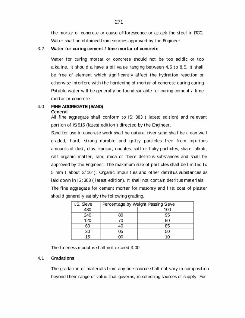
271
the mortar or concrete or cause efflorescence or attack the steel in RCC.
Water shall be obtained from sources approved by the Engineer.
3.2 Water for curing cement / lime mortar of concrete
Water for curing mortar or concrete should not be too acidic or too
alkaline. It should a have a pH value ranging between 4.5 to 8.5. It shall
be free of element which significantly affect the hydration reaction or
otherwise interfere with the hardening of mortar of concrete during curing
Potable water will be generally be found suitable for curing cement / lime
mortar or concrete.
4.0 FINE AGGREGATE (SAND) General
All fine aggregate shall conform to IS: 383 ( latest edition) and relevant
portion of IS:515 (latest edition ) directed by the Engineer.
Sand for use in concrete work shall be natural river sand shall be clean well
graded, hard, strong durable and gritty particles free from injurious
amounts of dust, clay, kankar, nodules, soft or flaky particles, shale, alkali,
salt organic matter, lam, mica or there detritus substances and shall be
approved by the Engineer. The maximum size of particles shall be limited to
5 mm ( about 3/16”). Organic impurities and other detritus substances as
laid down in IS :383 ( latest edition). It shall not contain detritus materials
The fine aggregate for cement mortar for masonry and first coat of plaster
should generally satisfy the following grading.
I.S. Sieve Percentage by Weight Passing Sieve 480 100 240 80 95 120 70 90 60 40 85 30 05 50 15 00 10
The fineness modulus shall not exceed 3.00
4.1 Gradations
The gradation of materials from any one source shall not vary in composition
beyond their range of value that governs, in selecting sources of supply. For
272
determining the degree of uniformity, determination of fitness modulus
shall be made upon representative sample furnished by the contractor from
such source as the proposes to use. Fine aggregate from any one source
having variation in fineness modulus greater than ±0.20 from the average
fineness modulus of the representative samples submitted by the contractor
shall be rejected or may be accepted subject such changes in the
proportion aggregate as the Engineer may direct
4.2 Storage
The fine aggregate should be stacked carefully on a clean, hard surface
so that it will not mixed up with detritus foreign materials.
5.0 Coarse Aggregate
Coarse aggregate shall consist of crushed or broken stones and be hard,
strong, dense, durable clear or proper gradation and free from skin and
coating likely to prevent proper adhesion of mortar. The aggregate shall
generally be cubical in shape and as far as possible flurry, elongated
pieces shall be avoided. It shall generally comply with the provision of IS
: 383 and IS:515 ( latest edition).
The maximum size of the aggregate may be up to 20 mm and well graded
between the sixes 5 mm to 20 mm in such proportions as to give
maximum density to the concrete. The maximum size should be as large
as possible within the above limit but should not exceed ¼ of the
minimum thickness of the member provided, however, this size present
no difficulty in the case of RCC to surround the reinforcement thoroughly
and fill up the corners of the form work satisfactorily. In the case of
general concrete work, a maximum size of 40 mm ( about 1/22’ ) is used
and in RCC work a maximum size of 20 mm (about 1 ¼”) will be found
satisfactory, but it should be restricted to 6 mm ( about ¼”) less than the
minimum lateral clear distance between bars or 6 mm ( about ¼”) less
than the cover, whichever is smaller.
273
The crushing strength of aggregate will be such as to allow the concrete
in which it is used to build up the specified strength of concrete.
Approximate range, in grading of coarse aggregate may be as required.
Grading tests shall be in the beginning and at change of surface of
machinery or type of metal. Where required by the Engineer, tests
indicated in IS: 368 and IS: 456 (latest edition) shall be got carried out in
an approved laboratory at the contractor’s cost to show the acceptability
of the material.
Coarse aggregate of a porous nature where absorption of water after 24
hours immersion in water, is more than 5 percent by weight, shall not be
used
Limit of deleterious substance shall not exceed those prescribed in IS :
515 ( latest edition)
5.1 Storage
The aggregate of different sizes shall be stored separately and handled in
such manner as to prevent intermixing of different sizes of aggregate
required separately for grading purposes. No foreign matter shall be
allowed to be mixed up with aggregated. If covered with dust etc. they
shall be washed clean before use.
6.0 MIXING
For all important woks concrete shall be mixed in mechanical mixer at
the site of work. Care shall be taken to see that the mixer or other
accessories are in first class working condition and maintained so
throughout the construction. Mixing shall be continued till there is
uniform colour is obtained and each individual article of the coarse
aggregate shall show a complete coating of mortar contain in its
proportionate amount of cement. In no case mixing shall be done for less
than 1 ½ minutes.
274
6.1 When hand mixing is permitted by the Engineer it shall be done on a
smooth water tight platform large enough to allow efficient turning over
of the ingredient of concrete before and after adding water. Mixing
platform shall be so arranged that no foreign materials shall be get mixed
water shall flow out.
6.2 The cement is required number of bags shall be placed in a uniform layer
on top of the measure quantity of fine aggregate required, also spread in
a layer of uniforms depth in the mixing platform. Dry sand and cement
shall then be mixed thoroughly by turning over to get a mixture of
uniform colour. Enough water then be added gradually through a rose and
the mass turned over till a mortar of required consistency is obtained.
The measured quantity of coarse aggregate shall then be placed on the
mixing platform and wetted and the mortar added and the entire mss
turned and returned until all the particles of the coarse aggregate are
fully covered with mortar and the mixture is of a uniform colour and
required consistency. In hand mixing quantity of cement shall be
increased by 5% above the specified
6.3 Concrete shall have a consistency such that it will be workable in the
required position and in the case of RCC flow around reinforcing steel
also.
6.4 For vibrated concrete slump shall range between 2.5 to 5 cm ( about 1 “
to 2”) For hand tamped concrete, slump shall range between 8 cm to 13
cm ) 3” t 5” according to the type and nature of the concrete item. The
sump shall be the latest permitted by workability. The slump shall be
determined as detailed in relevant IS code provisions and maintained
throughout the concreting operation of a member.
The concrete shall be placed in its final position and rammed, vibrated
and finished within 30 minutes of adding water to cement. Re-tempering
or remixing of partially hardened concrete shall not be permitted. Mixing
shall be done only by mechanical mixer.

275
6.5 Transporting
The concrete shall be handled from the place of mixing to the final
position as quickly as practicable by methods which will prevent
segregation and loss of ingredients. In no case shall the operation take
more than 15 minutes.
6.6 Placing
The concrete shall be placed into its final position, compacted and
finished within 30 minutes of mixing the water and before setting
commences. The method of placing shall be such as to avoid segregation.
Placing shall be done in balanced manner to avoid eccentric loads form
work.
As far as practicable the concrete for particular portion shall be done in
one continuous operation. The construction joints when required shall
made only where located on the plans or shown in the pouring schedule
unless otherwise approved by the Engineer. The joint shall be vertical
and shall be made by placing a bulk head at the joint. Before
commencing subsequent concreting, all loose particles, laitance etc. shall
be removed and the surface shall then be covered by thick cement slurry
as part of placement. Care shall be taken during the placing not to
disturb the forms or the reinforcement. Concrete compacted manually,
shall preferably be laid in layers of 51 cm to 20 cm ( about 6“ to 8”) the
layers being decided by the time lapse between the successive layers.
The time of laying one layer shall not exceed 30 minutes. The successive
layers shall commence within 30 minutes of laying first layer.
When work is to be resumed on a surface which has hardened, such a
surface shall be roughened and scrubbed with brushes to remove
laitance, care being taken to avoid dislodgment of coarse aggregate,
swept clean thoroughly wetted and covered with 6 mm (about 1”) thick
mortar layer composed of cement ad sand in the same proportion as the
cement and sand in the concrete for securing good bond.
276
The concrete shall be normally laid in the dry. If they are under water, it
shall be pumped dry and kept so while placing concrete and till it sets.
Where it is necessary to deposit concrete under water, it shall be done as
per relevant IS code provisions (latest edition). No extra payment will be
made for the special arrangements, plants, and etc. need for the purpose
or for the additional 10% cement required to be added.
7.0 COMPACTING
The concrete shall be thoroughly compacted during depositing to get a
dense concrete and thoroughly worked into the edges and corners of the
form work as also along its faces and around reinforcement in the case of
RCC by means of suitable tools such as spades and rods to get a good case
finished without honey combing. Concrete shall not disturb once it is set.
Concrete shall not be disturbed once it is set.
For important or big works where stiffer mix with less slump is adopted,
use of mechanical vibrators is essential. The vibrators shall have not less
than 3600 and preferably about 5000 impulses per minute and shall be
worked at an interval of about 60 cm (about 2”). It shall be worked in
one place for only such time as will also formation of dense concrete
without sinking and segregation of the coarse aggregate over vibration
shall be avoided.. Vibration shall be added by spreading and Roding.
Compaction shall necessarily be done by mechanical vibrators. No hand
compaction will be permitted except (I) to supplement vibration near the
edge and faces of forms, to fill the corners completely and to prevent
honey combing or (ii) in members where vibration is not possible nor
desirable in the opinion of the Engineer.
8.0 CURING
The contractor shall be initially protected for damage on account of impact,
undue pressure and excessive head of sub, rains etc. and covered with wet
of stacking Hessians or similar absorbent material soon after the initial set.

277
After the final set, the concrete shall be kept continuously wet preferably
by pounding water for period of not less than 14 days from the date of
placement . On Sunday, holidays and days of cessation of work,
arrangement shall be made to keep the concrete continuously watered.
Should the contractor fail to water the concrete continuously, the
Engineer may provide labour materials, and equipments required for
watering and recover the costs from the contractor. When atmospheric
temperature exceeds 40°C (104 °F) following precautions should be taken
1. Stacking aggregate under shade and keeping them moist
2. Using cold water
3. Reduce the time between mixing and placing to the minimum
4. Cooling form work by drinking water
5. Starting curing before concrete dries out
6. Restricting concreting to morning and evenings.
9.0 FINISHING
Immediately after the removal of forms and undulations, depressions,
cavities, honey combing broken edges or corners, high spots and other
defects shall be made good and finished with cement mortar 1:2. But the
necessity of such finishing must be exceptional and the total surface
requiring finishing shall not exceed 1% on a average. IF the initial
experience shows that this percentage is exceeded the method of
working itself should be changed to get the required cast finish.
Where the concrete surface is to receive plaster, the surface shall be
roughened immediately after removal of forms and within a day thereof
to secure a bold for the plaster. The rate for concrete is inclusive of this
roughening and finishing. Concrete after finishing shall be cured for the
full period
278
10.0 Re-tempering
Concrete shall be mixed only in such quantities as are required for
immediately use and any concrete which has developed initial set shall
not be re-tempered or remixed but shall be destroyed or thrown away.
13.0 Cement Plaster with Water Proof Compound
20 mm thick cement plaster with CM 1:3 proportion with waterproof
compound shall be provided to the container from inside (including roof
beams and roof slabs etc.)
14.0 M.S. Ladder
One numbers of M.S. ladder shall be provided and fixed to give access
into the tank through manhole in the roof slab. The ladder shall be
comprising of M.S. approved section placed at 45 cm, apart with M.S.
Bars of approved dia. in double rows as steps at 20 cm c/c. The ladder
shall be encased by C.C. at both the ends.
15.0 C.I. manhole frame and Cover
Providing and fixing of C.I. manhole frame and cover of best quality
having required size with locking arrangement weighing not less than 35
Kg. including 2 coats of anticorrosive paint etc.
16.0 Water Proof Cement Paint
Three coats of water proof cement paint of syntax mat manufacture and
approved colour scheme by the MJP shade to all outside portion of sump
etc. complete as directed Engineer-in-charge.
17.0 Epoxy Painting Providing and applying special epoxy paint of standard approved make in
two coats to the inside surface of the container and roof / floor slab, free
board including necessary scaffolding etc complete as directed.
279
18.0 PIPE LAYING PROCEDURE:
The contractor shall lower the pipes of standard lengths. Short length
pipes shall be lowered only if found necessary and only after obtaining
the permission of Engineer-in-Charge. The pipes shall be lowered in the
trench on prepared bedding or concrete bedding as per the decision of
Engineer-in-Charge. Pipes shall not be laid on the open rock bottom as it
may damage the pipe shell on account of point loads.
19.0 FIXING SLUICE VALVES
The specification lays down the requirement for lowering, laying and
jointing Sluice valves.
1.0 PREPARATION
The sluice valves and tail pieces shall be examined before laying for
cracks and other flows. Only undamaged S.V. shall be used.
The sluice valve shall be operated and checked before laying.
All the four faces shall be thoroughly cleaned and coated with a thin
layer of mineral grease.
The tightening of gland shall be checked with a pair of inside calipers.
Clearance between the top of stuffing box and the underside of the gland
shall be uniform on all sides.
2.0 JOINTING MATERIALS
The contractor shall provide all the necessary jointing materials such as
nuts, bolts, rubber packing, white zinc, jute lead wool etc. at his cost.
All tools and plant required for installation of sluice valve shall be
provided by the contractor at his cost.
All the jointing materials shall be got approved from the Engineer-in-
charge before use.

280
The nuts and bolts shall be conform I.S.1364 and the rubber packing shall
conform I.S. 638.
3.0 INSTALLATION
The sluice valve shall be lowered into trenches carefully so that no part is
damaged during lowering operation. If necessary tail pieces shall be
fitted with sluice valve first outside the trench and then lowered into the
trench.
The rubber packing shall be three ply and of approved thickness. The
packing shall be of full diameter of the flange with necessary holes and
the sluice valve bore. It shall be even at both the inner and outer edge.
The flange faces shall be thoroughly greased. If flanges are not free the
contractor shall use thin fibers of lead.
After placing the packing, nuts and bolts shall be inserted and tightened
to make the joint. The valve shall be tightly closed being installed to
prevent any foreign materials from getting in between the working parts
of the valve.
Each flange bolt shall be tightened a little at a time taking care to
tighten diametrically opposite bolts alternately.
The sluice valve shall be installed in such a way that spindle shall remain
in truly vertical position.
The other end of the tail piece shall be fitted with pipes so that
continuous lines can work. Extra excavation necessary for facility of
lowering and fixing of sluice valve shall not be paid for.
4.0 TESTING
After installation of sluice valve the same shall be tested to 1.1/2 times
of is test pressure.
The joints of sluice valve shall with stand the test pressure of pipeline.

281
Defects noticed during test and operation of sluice valve shall be
rectified by the contractor at his own cost, without any extra claim, to
the entire satisfaction of the Engineer-in-charge.
20.0 B.B. MASONRY CHAMBER
The size of the chamber shall be as per requirement and as per direction
of Engineer –in-charge.
The tender item covers excavation required in wet and dry CC at bottom
on well rammed surface and B.B. masonry walls with inside cement
plaster and cement pointing from outside and CC coping on the top of
B.B. masonry. The work of CC and B.B. masonry shall be carried out as
per detailed specification of respective items. The covers shall be of
precast slab. This shall include the cost of reinforcement, concrete.
Precasting, curing, conveyance and fixing the RCC precast cover.
The work shall be carried out as per detailed drawing of the chamber
supplied by the Engineer in charge. The chamber shall be flush with road
surface and shall not cause any hindrance to the traffic.

282
OBLIGATORY CONDITIONS FOR R.C.C. SUMP.
The contractor will have to submit his tender on his own design, the basic
requirements such as capacity, bottom RL and FSL are obligatory. It is
further to point out that the water depth cannot be changed. Conditions
each sump. and the specification of various items as detailed below will
remain same of
1 Location Bhendipada Ambernath Booster Police Quarter Ambernath
Gaon
2 Capacity of sump 2.0 ML 1.5 ML 0.85 ML 0.10 ML
3 Type of Construction RCC M-300 RCC M-300 RCC M-300 RCC M-300
4 Shape Rectangular Rectangular Rectangular/Circular
Rectangular/Circular
5 Average G.L. at site 30.0 m 15.20 m 23.00 m 56.00 m
6 F.S.L. of sump 30.5 m 15.70 m 23.50 m 56.50 m
7 Bottom R.L. of sump 28.0 m 12.70 m 21.00 m 54.00 m
8 Levelling Course PCC M-150 PCC M-150 PCC M-150 PCC M-150
9 Size of M.H frame & cover
0.90 m X 0.60 m 0.90 m X 0.60 m 0.90 m X 0.60 m 0.90 m X 0.60 m
10 Plaster
20 mm thick in C.M. 1:3 from inside & outside with water proofing compound & epoxy painting from inside
20 mm thick in C.M. 1:3 from inside & outside with water proofing compound & epoxy painting from inside
20 mm thick in C.M. 1:3 from inside & outside with water proofing compound & epoxy painting from inside
20 mm thick in C.M. 1:3 from inside & outside with water proofing compound & epoxy painting from inside
11 Ladder M.S. ladder of 0.50 m width
M.S. ladder of 0.50 m width
M.S. ladder of 0.50 m width
M.S. ladder of 0.50 m width
12 Gallery at floor level
Width 1.2 m with G.I. pipe railing ( 3 rows of 25 mm G.I. pipe)
Width 1.2 m with G.I. pipe railing ( 3 rows of 25 mm G.I. pipe)
Width 1.2 m with G.I. pipe railing ( 3 rows of 25 mm G.I. pipe)
Width 1.2 m with G.I. pipe railing ( 3 rows of 25 mm G.I. pipe)
283
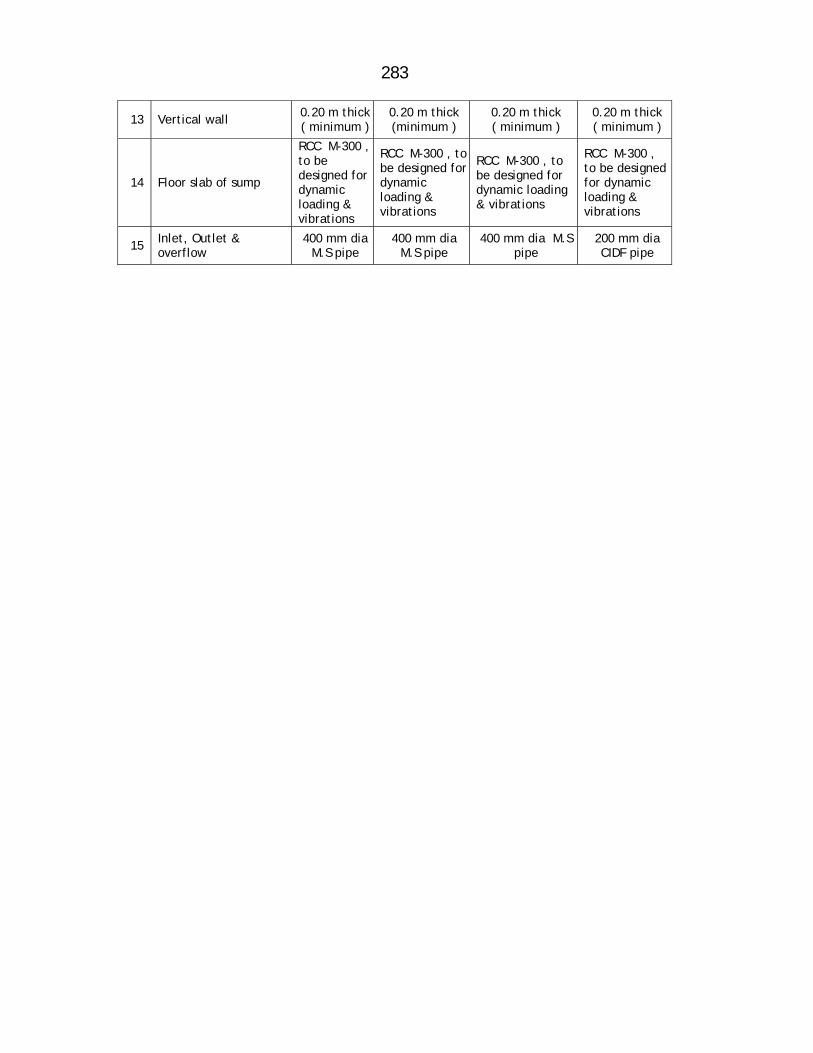
13 Vertical wall 0.20 m thick ( minimum )
0.20 m thick (minimum )
0.20 m thick ( minimum )
0.20 m thick ( minimum )
14 Floor slab of sump
RCC M-300 , to be designed for dynamic loading & vibrations
RCC M-300 , to be designed for dynamic loading & vibrations
RCC M-300 , to be designed for dynamic loading & vibrations
RCC M-300 , to be designed for dynamic loading & vibrations
15 Inlet, Outlet & overflow
400 mm dia M.S pipe
400 mm dia M.S pipe
400 mm dia M.S pipe
200 mm dia CIDF pipe
284
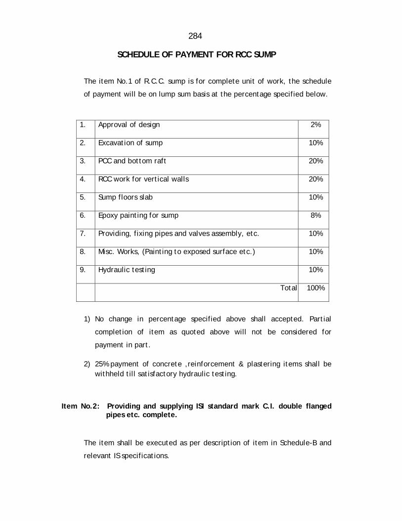
SCHEDULE OF PAYMENT FOR RCC SUMP
The item No.1 of R.C.C. sump is for complete unit of work, the schedule
of payment will be on lump sum basis at the percentage specified below.
1. Approval of design 2%
2. Excavation of sump 10%
3. PCC and bottom raft 20%
4. RCC work for vertical walls 20%
5. Sump floors slab 10%
6. Epoxy painting for sump 8%
7. Providing, fixing pipes and valves assembly, etc. 10%
8. Misc. Works, (Painting to exposed surface etc.) 10%
9. Hydraulic testing 10%
Total 100%
1) No change in percentage specified above shall accepted. Partial
completion of item as quoted above will not be considered for
payment in part.
2) 25% payment of concrete ,reinforcement & plastering items shall be withheld till satisfactory hydraulic testing.
Item No.2: Providing and supplying ISI standard mark C.I. double flanged pipes etc. complete.
The item shall be executed as per description of item in Schedule-B and
relevant IS specifications.
285
Mode of measurement and payment
The item shall be measured and paid on Rmt basis. 85% payment shall be
released after supply of pipes with manufacturers test report, 15% after
jointing and satisfactory hydraulic testing of pipe.
Item No-3:- Providing spirally welded M.S. pipes 1. Pipes to be supplied under this contract shall conform to IS: 3589,
5504:2001, Indian Standard for Electric Spirally welded steel pipes for
water, gas and sewage (subject to specific requirements given below).
2. In case supplier proposes to supply pipes to the standards superior to the
above standards no weightage will be given while evaluating the bid and
for payment.
3. The supply of M.S. pipes is for Bhendi pada & Ambernath booster sumps.
Location The destination will be as per directives of the Engineer-in-charge.
Specific Requirements a) Details of Supply Inner dia 400 mm
Thickness 10 mm
Test Pressure 10 Kg/Sqcm
I.S. Code: IS: 3589:2001, IS: 5504:2001, Fe. 410 MP, A Grade Steel
Method of Manufacture
a) Electrical resistance welded and Induction welded ERW
b) Electric Fusion (Arc) welded EFW
Applicable Standards (with Latest Edition)
Submerged are welded SAW

286
c) IS: 3589, IS: 5504:2001, Specification for electrically welded steel pipes
for water gas and sewerage. Arc welding of carbon and carbon
manganese steels, steel (Standard Quality).
d) IS: 2062:1980, Structural steel (fusion welding quality)
e) IS: 4711:1984, methods of sampling of steel pipes, tubes and fittings.
f) IS: 1894:1972, method of tensile testing of steel tubes. g) IS: 5822:1994, Code of Practice for laying and jointing M.S. pipes h) IS: 228:1994 IS: 1608:1995, IS: 2328:1983, IS: 3803:1989
Thickness
Though it is specified in IS: 3589:2001 no negative tolerance in thickness shall
be entertained. Only positive tolerance shall be accepted.
Straightness Finished pipe shall not deviate from straightness by more than 0.2% of the total
length or 6 mm which is lower.
Hydraulic pressure test Each pipe shall be hydraulically tested at manufacturer's works. The hydraulic
test pressure is calculated from the formula given below.
P = 2st D Where,
P = Test pressure in MPa
S = Stress in Mpa which is taken as 40% of the specified minimum tensile strength.
T = Specified thickness in mm D = Specified outside diameter in mm
287
Mode of Payment of Providing M.S. Pipes
85% immediately, after providing of pipes on site
15% after lowering, laying and jointing of pipes and satisfactory
hydraulic testing of the pipe line.
After laying the entire pipeline, if there is any surplus pipes which are
decided to be retained by the MJP., the 100% of the rate of supply shall
be payable after stacking properly in the MJP store within the project
area.
Item No-4: Providing & Fabricating M S Specials etc complete’
The scope or special specifications shall cover the following works under
the contract.
Providing, fabricating M.S. Plates for specials for works, testing etc. at
the Contractor’s factory and testing the pipes
Transporting of fabricated specials from contractor’s factory to laying
site or MJP’s store as directed
These specials (detailed hereafter) specifications supplement, Standard
Specifications for Civil Construction Works prepared by the MJP for
(Maharashtra Jeeven Pradhikaran)
DRAWINGS
Working drawings shall have to be prepared by the Contractor.
SUPPLY OF MATERIALS TO THE CONTRACTOR
The MJP will not supply M.S. Materials such as plates; flats etc. required
for the fabrication of pipes, specials appurtenances etc.
The conveyance of fabricated materials from workshop to site of work shall
be deemed to have been covered in the relevant items of fabrication of
pipes, specials etc. The contractor should note that the steel plates and
288
other structural steel required for fabrication of specials is to be procured
by him from open market at his cost. The contractor has to procure such
plates in several stages as the circumstances demand, or, as directed by
Engineer-in-Charge.
GENERAL
The main specials and appurtenances to be fabricated under this contract
are as per list following which is inclusive. The typical drawings for these
are accompanying / or may be provided during execution.
a) One piece cut composite bends. b) Loose flange rings c) Stiffener rings. d) Pressure and non-pressure type blank flanges e) ‘Y’ branches and tees, f) Tapers, bends and wearing plates, dished manhole
WORKMANSHIP
Loose Flange Rings
Loose flange rings shall be cut of the plates of suitable thickness as
directed by the Engineer. In order to avoid the wastage of steel plates
shall be cut in maximum 4 segments, to form a complete ring when
welded together. Bolt holes of required size at the exact c/c distance in
required pitch circle shall be drilled through the flange rings. They shall
be mounted and tack welded on pipes/ specials etc. as shown on the
drawing whenever required.
Stiffener Rings
Stiffener rings shall be cut out of the M.S. channel of suitable size as
required by the Engineer-in-Charge. In order to avoid wastage, these
shall be cut in segments to form rings when welded together. These shall
be provided on site in segments sand shall be welded on the pipes as per
instructions of the Engineer-in-Charge.
289
Tapers
The tapers and bend shall be fabricated in one or more pieces as may be
necessary according to their lengths and sizes of plates available. These
shall have stiffening rings fixed on them as per details supplied by the
Engineer-in-Charge during fabrication
Special Care to be taken during Fabrication of Composite Bends, Tees
and ‘Y’ Branches
The testing of these specials is not envisaged at the fabrication stage.
These shall be subjected to test when the completed pipeline is tested
hydraulically. In view of this, the contractor in his own interest shall
fabricate these specials with all the care so that there is no failure of any
welded joint during testing of the completed pipeline, which will invite
dewatering the main, repairing and retesting. If directed by Engineer-in-
Charge, the contractor will have to manufacture M.S. bends from the
available M.S. Pipes by cutting and welding the pipe pieces as required
including painting of specials fabricated with red oxide paint and a
covering coat of gray graphite paint. In such cases payment will be
proposed for cutting and welding operations under relevant item work
and payment will be made under this item.
MEASUREMENT AND PAYMENT
Fabrications of the various specials and appurtenances shall be measured
and paid under the relevant item in Schedule B on weight basis. These
items shall include the cost of supply of all labour, material and
machinery for fabricating theses and appurtenances as per specifications
and shall include all cost of materials and handling materials within the
fabrication yard stacking them properly in the yard, transporting from
factory to site, including loading, unloading and all other ancillary works
involved. Deductions for bolt holes shall not be made while computing
weight for payment. 85% payment will be made immediately after supply
290
of M.S. specials with test certificate. 15 % after satisfactory hydraulic
testing is given.
Item No-5: Providing and supplying ISI mark C.I. flanged S&S specials etc.
complete.
Providing and supplying ISI mark C.I. flanged S&S specials, including all
taxes (Central and local), railway freight, inspection charges, unloading
from railway wagon, loading into truck, transportation up to
departmental store/site of wok, unloading, stacking etc. complete.
Mode of measurement & payment
The item will be measured and paid on Kilogram Basis. 85% of the
payment Should be released after supply of specials at site and 15%
payment will be released after satisfactory hydraulic testing, is
completed.
Item No.6: Providing and supplying C.I.D.F. sluice valve etc. complete.
The contractor shall procure C.I.D.F Sluice valves with wheel as per
IS:2906-1969 and revised latest edition. Valves of PN-1 rating shall be
provided. Only Kirloskar, I.V.C., IVI, Durga, Mayur, make valves shall be
accepted.
Mode of measurement and payment
The item shall be measured and paid on per number basis. 85% payment
shall be released after supply of valves with manufacturers test report,
15% after jointing and satisfactory testing of valves.
Item No.7: Providing and applying Epoxy Paint (Coating)
Surface preparation for applying Epoxy Paint :- The Surface should be cleaned by wire brush, surface should be clean by
solvent degreasing and derusting by applying chemical method and
scaffolding if necessary.
291
The surface should be cleaned, dry, free from rust and mill scale, blast
cleaning should be done second quality BS:4232, minimum surface profile
not to exceed 100 microns. Where highly corrosive condition are exists,
blasting to first quality should be applied. Mill scale should be removed
for optimum performance. Remove all other contaminants, oil, grease
etc. by use on an aromatic solvent like xylol. The surface should be
clean and dry before priming.
Priming: Blast cleaned surface should be primed within four hours of
blasting.
Two coats of primer should be applied.
For airless spraying tip size 0.38 to 0.48 mm and pressure should be in
range of 110 to 150 Kg per square meter, and pump rating 23.1. It should
not be applied when temperature fall below 10 degree centigrade or
when relative humidity rises above 90% or during rain, fog or mist.
Brushes and spray equipment should be cleaned with thinner. For
conventional spraying use only standard equipments, providing pressure
2.5 to 3 kg. per square centimeters, stir base well before and after
adding catalyst.
Application of paint :- The paint should be equivalent such as Dr.Bake, Krishna, Conchem, Asian
Paint, Atul Limited, Berger Paint. Epoxy primer 50 to 60 microns thick and
covering two coats of 30 microns thick each should be applied new M.S.
Pipe as per instructions given by Manufacturer. For airless spraying tip size
0.61 mm and pressure should be in range of 110 to 160 Kg per square
centimeters, with pump ration 23:1. After mixing base & catalyst the
mixture should be allowed to mature for 30 minutes before being used.
Due health and safety care of labour and painter, should be taken by
contractor.
Testing :- Epoxy paint should be tested as per standards and results should be
submitted to MJP at agency’s own cost.

292
Mode of measurement and payment. Payment will be made on Sqm. basis after satisfaction of Engineer-in-
charge. 90% payment proposed against completion of paint work
satisfactory and 10% cost of work shall be retained till laboratory &
Manufacturer test certificate.

293
MAHARASHTRA JEEVAN PRADHIKARAN
MAHARASHTRA JEEVAN PRADHIKARAN W.M. CIRCLE, PANVEL
MAHARASHTRA JEEVAN PRADHIKARAN W.M. DIVISION , AMBERNATH
NAME OF WORK: Augmentation to Ambernath Water Supply Scheme, Tal. Ambernath, Dist. Thane Construction of C.C. weir at Chikhloli Dam, Designing,
constructing & commissioning 7.20 ML capacity WTP at Chikhloli, lowering, laying and jointing D.I.K-7/K-9 pipes for rising main/gravity main/distribution system, construction of R.C.C. sump and pump house, construction of 8 nos. of RCC ESRs at various places with compound wall, construction of Consumer Redressal Centre with computerization, Railway crossing work, Repairs to Belivali MBR etc. complete.
ITEMWISE DETAILED SPECIFICATIONS SUB WORK NO.3: CONSTRUCTION OF RCC PUMP HOUSE OVER SUMP WELL AT
BHENDIPADA,AMBERNATH BOOSTER, POLICE QUARTER & AMBERNATH GAON
The contractor shall quote his offer in Schedule ‘B’ for the complete
work of constructing Pump House to be carried out as per his own design based
on given date i.e. he shall tender the offer in Schedule ‘B’ for construction of
required size with his own design and drawings. The design shall be got checked
from the institutes like Govt. Engineer College. Ramarks shall be complied and
scrutiny charges shall be borne by the contractor.
1. The structural design of pump house shall conform to the following
standard specification and codes of practice of IS.
a) IS:456 Code of practice for plain and reinforced concrete (latest
edition)
b) IS:875 Code of practice for structural safety of building loading
standards. (Latest edition).
c) IS:3370 (Para I to IV) Code of practice for concrete structures of
storage of liquids. (Latest edition).

294
2. Following shall be the minimum thickness of various members of the
pump house.
Roof slab of pump house 120mm
Pump floor slab 200mm
Column 300mm
Beam 450mm
3. Pump House over pure water sump should have adequate area as per the
requirement to accommodate pumps.
4. The head room of minimum 6.50m with Ventilation of minimum 20%
5. The RCC frame structure including RCC columns, beams, lintels, Chajja,
slab in CC M-250 as per approved design including cost of reinforcement
bar, as per IS:13620-993 shall be used.
6. Water proofing treatment should be given to top slab of pump house.
7. The B.B. masonry wall of minimum thickness 23 cm in CM 1:6 with the
specification lays down the requirements for B.B. Masonry 1st class in
cement mortar of specified proportion required for various structures,
including necessary scaffolding, watering etc. The specifications shall
conform to IS: 2212-1991 its latest revision.
8. Rolling shutter fabricated from 18 gauge steel laths with side guides and
bottom rails, brackets, doors suspension shaft, rolling springs, lacking
arrangements and housing at the top, including mechanical gear
arrangement and painting should be provided as per the general
specification or as directed by Engineer-in-charge.
295
9. Powder coated aluminum windows fully glazed with M.S. grill as per PWD
Standard Specifications (Revised) and as the general specification as
directed by Engineer-in-charge.
10. 20mm thick sand faced cement plaster in CM 1:4 from outside and 12mm
thick from inside with neeru finish should be provided as per the general
specification as directed by Engineer-in-charge.
11. Snowcem painting, distempering and anti termed treatment should be
provided as per the general specification as directed by Engineer-in-
charge.
12. Shahabad stone Flooring shall be provided of 50mm thick Shahabad stone
with M-100 bedding as per the general specification as directed by
Engineer-in-charge.
13. The arrangement of cable tray trench, location of panel board, etc. as
per approved drawing.
14. The pump house columns shall be designed with corbels for 3 tons gantry.
The corbels should be provided at such height so that after installation of
gantry there will be sufficient working space between gantry and bottom
of roof beam.
15. For design of pump house floor, the impact factor should considered as
per pumping machinery to be provided, including Bowl assembly, pump,
motors and discharge head base frame, sole plate, column assembly
(including weight of water)
16. Painting the letter as directed in “Devnagari” such as the location,
capacity and other details on the pump house with oil paint of approved
colour and shade as given below.
296
These letters should be of size 0.60 x 0.45 m of approved colour and
shade including cost of all required materials for painting and preparing
the surface to receive paint including scaffolding if necessary etc.
complete as directed.
MATERIALS REQUIRED FOR CONSTRUCTION 1. Sand, Metal and Bricks
Sand, metal and bricks of best quality. Will be insisted. Samples of
these will have to be got approved from Engineer-in-charge prior to use
on work.
2. Cement
L & T / Ambuja / ACC/Birla Gold brand of 43 grade in jute/polyethylene
bags (weighing 50 Kg each) shall be used for all water retaining
structures.
3. Reinforcement
The steel to be used shall be grade Fe.415 as per design. The contractor
shall have to procure the steel from open market. The steel procured by
contractor shall be tested and the contractor shall produce
manufacturer’s test certificate without which it shall not be accepted.
Further the contractor shall arrange to get tested any samples from steel
brought at site by him in laboratory at his cost and result should be
submitted to the Maharashtra Jeevan Pradhikaran. The reinforcement are
to be provided with Fusion Bonded Epoxy paint. Defective steel brought
by contractor shall be rejected and will not be allowed to be used. Test
certificate stating the chemical composition and characteristics of the
product.
At least 3 samples of each diameter should be tested from every 5 ton or
part thereof. Tested lots only will be permitted to be used.
297
4. Concrete
The RCC works shall be as per IS 456-2000 or latest edition. Concrete mixer shall be used for preparing concrete. Vibrator shall be used to consolidate concrete while placing in position.
While concreting, respective samples in form of test cubes shall be taken
by the contractor under Maharashtra Jeevan Pradhikaran Supervisor and
shall be tested under his supervision. Charges of testing shall be borne
by the contractor.
Requirement of Materials 1. Cement shall be Ordinary Portland Cement
The measurement of proportion of cement should normally be on the
basis of weight and whole bags, each undisturbed and sealed 50 Kg bag
being considered equivalent to 35 liters (1.2 Cuft.) in volume. When part
bag is required, cement shall be taken by weight. Care should be taken to
see that each bag contains full quantity of cement.
Tests
When tests are considered necessary, they shall be carried out as
indicated in IS : 269. The contractor should ensure that the cement is of
sound and required quality before using
2 Storage
Cement required for use shall be as fresh as possible and stored on planks
raised 15 to 20 cms ( about 6” to 8”) above the floor and stacked 30 cm (
about 12” ) away from the walls in suitable closed weather proof
buildings at the work site or at the selected approved site, in such a
manner as to prevent deterioration by dampness or moist atmosphere or
instruction of foreign matter..)

298
2.1 Any cement which has deteriorated, baked or which has been damaged
shall not be used. Cement that is condemned shall be immediately
removed from the work site.. Ordinary cement stored for more than 2
months from the date of receipt from the factory shall be subjected to
test and used only if found satisfactory.. Cement shall be kept in a store
under double locking arrangement so that it can be taken our or fresh
stock admitted with the knowledge of supervising staff of the
Department.
3.0 WATER 3.1 Water for mixing cement lime mortar or cement lime concrete shall not
be salty or brackish and shall be clean, reasonably clear and free from
objectionable quantities of silt and tracers of oil, acid injurious alkali,
salts, organic matter and other detritus material which will either waken
the mortar or concrete or cause efflorescence or attack the steel in RCC.
Water shall be obtained from sources approved by the Engineer.
3.2 Water for curing cement / lime mortar of concrete
Water for curing mortar or concrete should not be too acidic or too
alkaline. It should a have a pH value ranging between 4.5 to 8.5. It shall
be free of element which significantly affect the hydration reaction or
otherwise interfere with the hardening of mortar of concrete during
curing.
Portable water will be generally be found suitable for curing cement /
lime mortar or concrete.
4.0 FINE AGGREGATE (SAND) General
All fine aggregate shall conform to IS: 383 ( latest edition) and relevant
portion of IS:515 (latest edition ) directed by the Engineer.
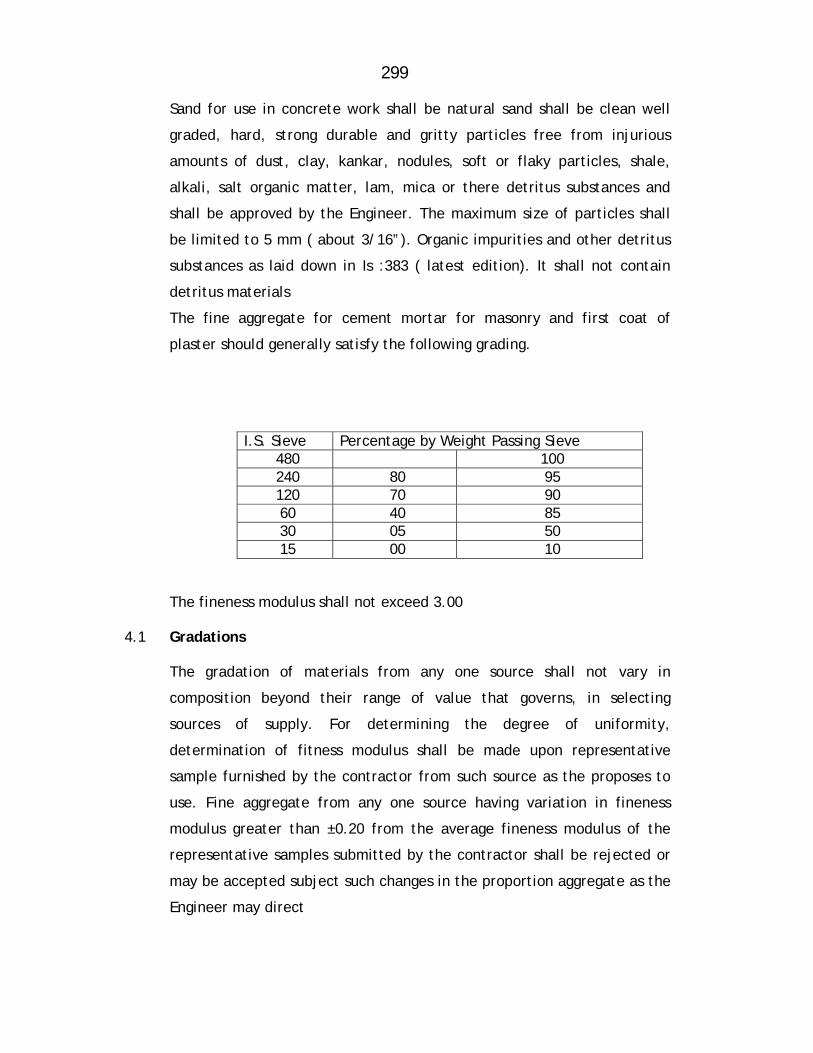
299
Sand for use in concrete work shall be natural sand shall be clean well
graded, hard, strong durable and gritty particles free from injurious
amounts of dust, clay, kankar, nodules, soft or flaky particles, shale,
alkali, salt organic matter, lam, mica or there detritus substances and
shall be approved by the Engineer. The maximum size of particles shall
be limited to 5 mm ( about 3/16”). Organic impurities and other detritus
substances as laid down in Is :383 ( latest edition). It shall not contain
detritus materials
The fine aggregate for cement mortar for masonry and first coat of
plaster should generally satisfy the following grading.
I.S. Sieve Percentage by Weight Passing Sieve
480 100 240 80 95 120 70 90 60 40 85 30 05 50 15 00 10
The fineness modulus shall not exceed 3.00 4.1 Gradations
The gradation of materials from any one source shall not vary in
composition beyond their range of value that governs, in selecting
sources of supply. For determining the degree of uniformity,
determination of fitness modulus shall be made upon representative
sample furnished by the contractor from such source as the proposes to
use. Fine aggregate from any one source having variation in fineness
modulus greater than ±0.20 from the average fineness modulus of the
representative samples submitted by the contractor shall be rejected or
may be accepted subject such changes in the proportion aggregate as the
Engineer may direct

300
4.2 Storage The fine aggregate should be stacked carefully on a clean, hard surface
so that it will not mixed up with detritus foreign materials.
5.0 Coarse Aggregate Coarse aggregate shall consist of crushed or broken stones and be hard,
strong, dense, durable clear or proper gradation and free from skin and
coating likely to prevent proper adhesion of mortar. The aggregate shall
generally be cubical in shape and as far as possible flurry, elongated
pieces shall be avoided. It shall generally comply with the provision of IS:
383 and IS:515 ( latest edition).
The maximum size of the aggregate may be up to 20 mm and well graded
between the sixes 5 mm to 20 mm in such proportions as to give
maximum density to the concrete. The maximum size should be as large
as possible within the above limit but should not exceed ¼ of the
minimum thickness of the member provided, however, this size present
no difficulty in the case of RCC to surround the reinforcement thoroughly
and fill up the corners of the form work satisfactorily. In the case of
general concrete work, a maximum size of 40 mm ( about 1/22’ ) is used
and in RCC work a maximum size of 20 mm (about 1 ¼”) will be found
satisfactory, but it should be restricted to 6 mm ( about ¼”) less than the
minimum lateral clear distance between bars or 6 mm ( about ¼”) less
than the cover, whichever is smaller.
The crushing strength of aggregate will be such as to allow the concrete
in which it is used to build up the specified strength of concrete.
Approximate range, in grading of coarse aggregate may be as required.

301
Grading tests shall be in the beginning and at change of surface of
machinery or type of metal. Where required by the Engineer, tests
indicated in IS: 368 and IS: 456 (latest edition) shall be got carried out in
an approved laboratory at the contractor’s cost to show the acceptability
of the material.
Coarse aggregate of a porous nature where absorption of water after 24
hours immersion in water, is more than 5 percent by weight, shall not be
used
Limit of deleterious substance shall not exceed those prescribed in IS :
515 ( latest edition)
5.1 Storage The aggregate of different sixes shall be stored separately and handled in
such manner as to prevent intermixing of different sixes of aggregate
required separately for grading purposes. No foreign matter shall be
allowed to be mixed up with aggregated. If covered with dust etc. they
shall be washed clean before use.
6.0 MIXING For all important woks concrete shall be mixed in mechanical mixer at
the site of work. Care shall be taken to see that the mixer or other
accessories are in first class working condition and maintained so
throughout the construction. Mixing shall be continued till there is
uniform colour is obtained and each individual article of the coarse
aggregate shall show a complete coating of mortar contain in its
proportionate amount of cement. In no case mixing shall be done for less
than 1 ½ minutes.
6.1 When hand mixing is permitted by the Engineer it shall be done on a
smooth water tight platform large enough to allow efficient turning over
of the ingredient of concrete before and after adding water.

302
Mixing platform shall be so arranged that no foreign materials shall be get
mixed water shall flow out.
6.2 The cement is required number of bags shall be placed in a uniform layer
on top of the measure quantity of fine aggregate required, also spread in
a layer of uniforms depth in the mixing platform. Dry sand and cement
shall then be mixed thoroughly by turning over to get a mixture of
uniform colour. Enough water then be added gradually through a rose and
the mass turned over till a mortar of required consistency is obtained.
The measured quantity of coarse aggregate shall then be placed on the
mixing platform and wetted and the mortar added and the entire mss
turned and returned until all the particles of the coarse aggregate are
fully covered with mortar and the mixture is of a uniform colour and
required consistency. In hand mixing quantity of cement shall be
increased by 5% above the specified.
6.3 Concrete shall have a consistency such that it will be workable in the
required position and in the case of RCC flow around reinforcing steel
also.
6.4 For vibrated concrete slump shall range between 2.5 to 5 cm ( about 1 “
to 2”) For hand tamped concrete, slump shall range between 8 cm to 13
cm ) 3” t 5” according to the type and nature of the concrete item. The
sump shall be the latest permitted by workability. The slump shall be
determined as detailed in relevant IS code provisions and maintained
throughout the concreting operation of a member.
The concrete shall be placed n its final position and rammed, vibrated
and finished within 30 minutes of adding water to cement. Re-tempering
or remixing of partially hardened concrete shall not permitted. Mixing
shall be done only by mechanical mixer
303
6.5 Transporting
The concrete shall be handled from the place of mixing to the final
position as quickly as practicable by methods which will prevent
segregation and loss of ingredients. In no case shall the operation take
more than 15 minutes
6.6 Placing
The concrete shall be placed into its final position, compacted and
finished within 30 minutes of mixing the water and before setting
commences. The method of placing shall be such as to avoid segregation.
Placing shall be done in balanced manner to avoid eccentric loads form
work.
As far as practicable the concrete for particular portion shall be done in
one continuous operation. The construction joints when required shall
made only where located on the plans or shown in the pouring schedule
unless otherwise approved by the Engineer. The joint shall be vertical
and shall be made by placing a bulk head at the joint. Before
commencing subsequent concreting, all loose particles, laitance etc. shall
be removed and the surface shall then be covered by thick cement slurry
as part of placement. Care shall be taken during the placing not to
disturb the forms or the reinforcement. Concrete compacted manually,
shall preferably be laid in layers of 51 cm to 20 cm ( about 6“ to 8”) the
layers being decided by the time lapse between the successive layers.
The time of laying one layer shall not exceed 30 minutes. The successive
layers shall commence within 30 minutes of laying first layer.
When work is to be resumed on a surface which has hardened, such a
surface shall be roughened and scrubbed with brushes to remove
laitance, care being taken to avoid dislodgment of coarse aggregate,
swept clean thoroughly wetted and covered with 6 mm (about 1”)
thick mortar layer composed of cement ad sand in the same
304
proportion as the cement and sand in the concrete for securing good
bond.
The concrete shall be normally laid in the dry. If they are in under
water, it shall be pumped dry and kept so while placing concrete
and till it sets. Where it is necessary to deposit concrete under
water, it shall be done as per relevant IS code provisions (latest
edition). No extra payment will be made for the special
arrangements, plants, etc. need for the purpose or for the
additional 10% cement required to be added.
7.0 COMPACTING
The concrete shall be thoroughly compacted during depositing to get
a dense concrete and thoroughly worked into the edges and corners
of the form work as also along its faces and around reinforcement in
the case of RCC by means of suitable tools such as spades and rods
to get a good case finished without honey combing. Concrete shall
not disturb once it is set. Concrete shall not be disturbed once it is
set.
For important or big works where stiffer mix with less slump is
adopted, use of mechanical vibrators is essential. The vibrators shall
have not less than 3600 and preferably about 5000 impulses per
minute and shall be worked at an interval of about 60 cm ( about
2”). It shall be worked in one place for only such time as will also
formation of dense concrete without sinking and segregation of the
coarse aggregate over vibration shall be avoided.. Vibration shall be
added by spreading and Roding.
Compaction shall necessarily be done by mechanical vibrators. No
hand compaction will be permitted except (I) to supplement
vibration near the edge and faces of forms, to fill the corners
305
completely and to prevent honey combing or (ii) in members where
vibration is not possible nor desirable in the opinion of the Engineer.
8.0 CURING
The contractor shall be initially protected from damage on account
of impact, undue pressure, excessive head of sub, rains etc. and
covered with wet of stacking Hessians or similar absorbent material
soon after the initial set. After the final set, the concrete shall be
kept continuously wet preferably by pounding water for period of
not less than 14 days from the date of placement. On Sunday,
holidays and days of cessation of work, arrangement shall be made
to keep the concrete continuously watered.
Should the contractor fail to water the concrete continuously, the
Engineer may provide labour materials, and equipments required for
watering and recover the costs from the contractor. When
atmospheric temperature exceeds 40°C (104 °F) following
precautions should be taken
1. Stacking aggregate under shade and keeping them moist
2. Using cold water
3. Reduce the time between mixing and placing to the minimum
4. Cooling form work by drinking water
5. Starting curing before concrete dries out
6. Restricting concreting to morning and evenings. 9.0 FINISHING
Immediately after the removal of forms and undulations, depressions,
cavities, honey combing broken edges or corners, high spots and
other defects shall be made good and finished with cement mortar
1:2. But the necessity of such finishing must be exceptional and the
total surface requiring finishing shall not exceed 1% on a average. IF
the initial experience shows that this
306
percentage is exceeded the method of working itself should be
changed to get the required cast finish.
Where the concrete surface is to receive plaster, the surface shall be
roughened immediately after removal of forms and within a day thereof
to secure a bold for the plaster. The rate for concrete is inclusive of this
roughening and finishing. Concrete after finishing shall be cured for the
full period.
10.0 Re-tempering
Concrete shall be mixed only in such quantities as are required for
immediately use and any concrete which has developed initial set shall
not be re-tempered or remixed but shall be destroyed or thrown away.
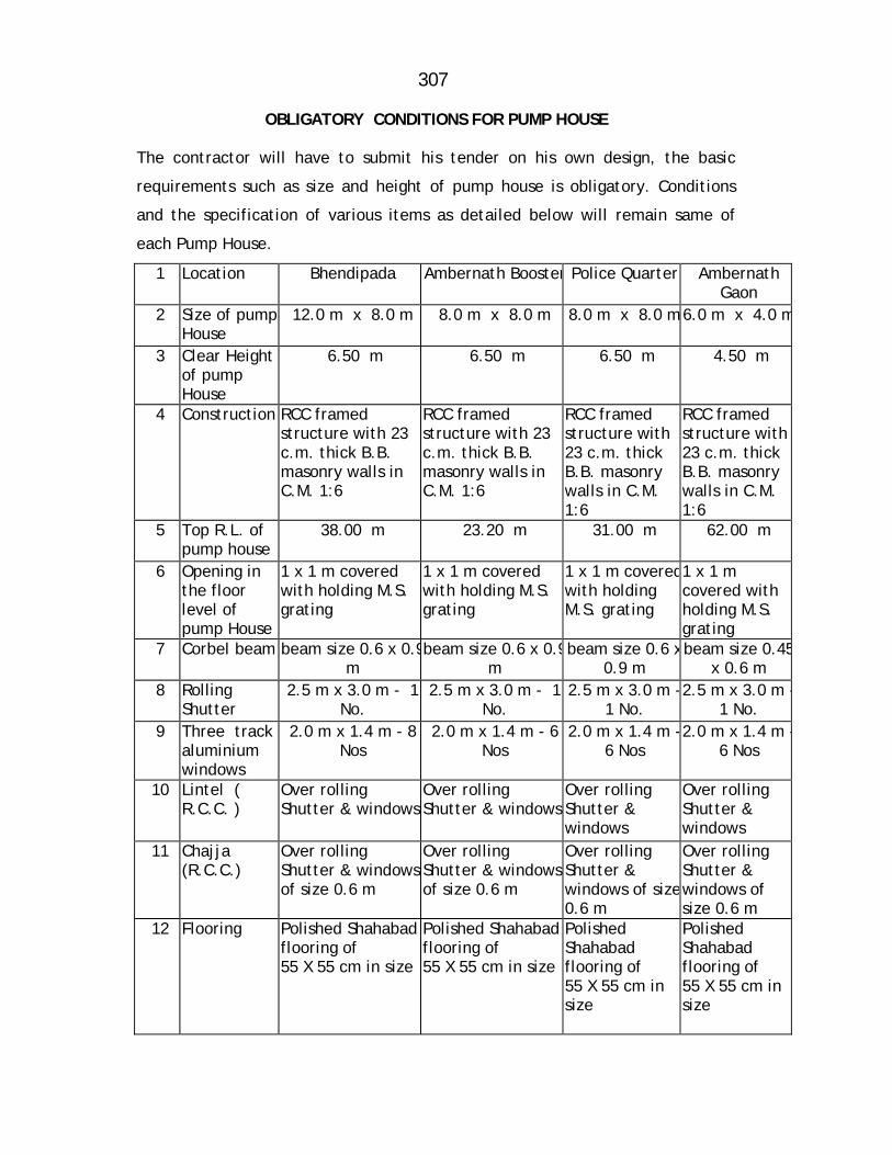
307
OBLIGATORY CONDITIONS FOR PUMP HOUSE The contractor will have to submit his tender on his own design, the basic
requirements such as size and height of pump house is obligatory. Conditions
and the specification of various items as detailed below will remain same of
each Pump House.
1 Location Bhendipada Ambernath Booster Police Quarter Ambernath Gaon
2 Size of pump House
12.0 m x 8.0 m 8.0 m x 8.0 m 8.0 m x 8.0 m6.0 m x 4.0 m
3 Clear Height of pump House
6.50 m 6.50 m 6.50 m 4.50 m
4 Construction RCC framed structure with 23 c.m. thick B.B. masonry walls in C.M. 1:6
RCC framed structure with 23 c.m. thick B.B. masonry walls in C.M. 1:6
RCC framed structure with 23 c.m. thick B.B. masonry walls in C.M. 1:6
RCC framed structure with 23 c.m. thick B.B. masonry walls in C.M. 1:6
5 Top R.L. of pump house
38.00 m 23.20 m 31.00 m 62.00 m
6 Opening in the floor level of pump House
1 x 1 m covered with holding M.S. grating
1 x 1 m covered with holding M.S. grating
1 x 1 m coveredwith holding M.S. grating
1 x 1 m covered with holding M.S. grating
7 Corbel beam beam size 0.6 x 0.9m
beam size 0.6 x 0.9m
beam size 0.6 x0.9 m
beam size 0.45x 0.6 m
8 Rolling Shutter
2.5 m x 3.0 m - 1 No.
2.5 m x 3.0 m - 1 No.
2.5 m x 3.0 m -1 No.
2.5 m x 3.0 m -1 No.
9 Three track aluminium windows
2.0 m x 1.4 m - 8 Nos
2.0 m x 1.4 m - 6 Nos
2.0 m x 1.4 m -6 Nos
2.0 m x 1.4 m -6 Nos
10 Lintel ( R.C.C. )
Over rolling Shutter & windows
Over rolling Shutter & windows
Over rolling Shutter & windows
Over rolling Shutter & windows
11 Chajja (R.C.C.)
Over rolling Shutter & windows of size 0.6 m
Over rolling Shutter & windows of size 0.6 m
Over rolling Shutter & windows of size0.6 m
Over rolling Shutter & windows of size 0.6 m
12 Flooring Polished Shahabad flooring of 55 X 55 cm in size
Polished Shahabad flooring of 55 X 55 cm in size
Polished Shahabad flooring of 55 X 55 cm in size
Polished Shahabad flooring of 55 X 55 cm in size
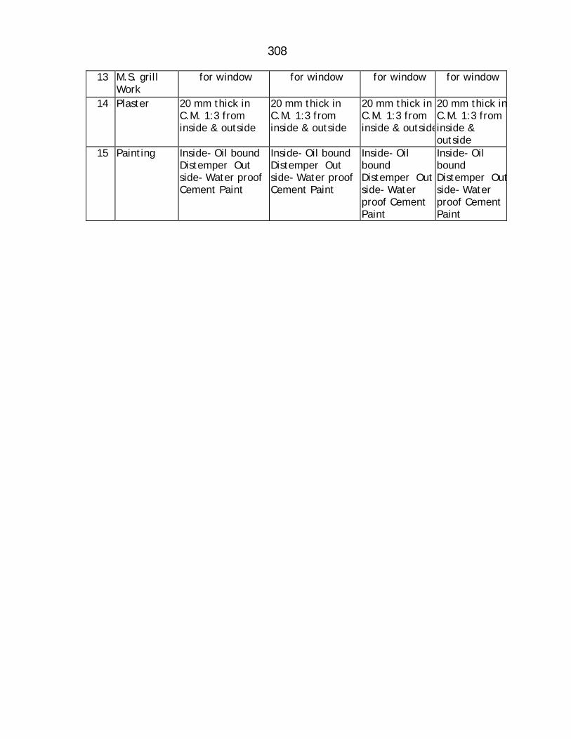
308
13 M.S. grill Work
for window for window for window for window
14 Plaster 20 mm thick in C.M. 1:3 from inside & outside
20 mm thick in C.M. 1:3 from inside & outside
20 mm thick in C.M. 1:3 from inside & outside
20 mm thick inC.M. 1:3 from inside & outside
15 Painting Inside- Oil bound Distemper Out side- Water proof Cement Paint
Inside- Oil bound Distemper Out side- Water proof Cement Paint
Inside- Oil bound Distemper Out side- Water proof Cement Paint
Inside- Oil bound Distemper Outside- Water proof Cement Paint
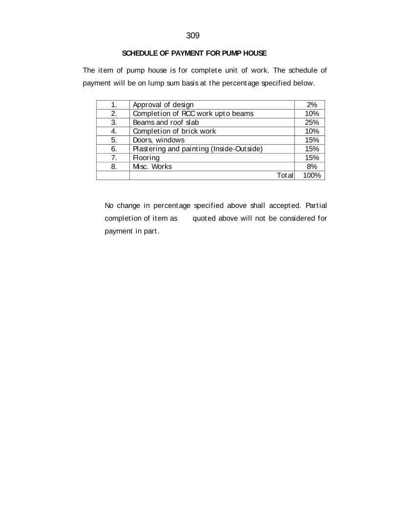
309
SCHEDULE OF PAYMENT FOR PUMP HOUSE
The item of pump house is for complete unit of work. The schedule of
payment will be on lump sum basis at the percentage specified below.
1. Approval of design 2% 2. Completion of RCC work upto beams 10% 3. Beams and roof slab 25% 4. Completion of brick work 10% 5. Doors, windows 15% 6. Plastering and painting (Inside-Outside) 15% 7. Flooring 15% 8. Misc. Works 8%
Total 100%
No change in percentage specified above shall accepted. Partial
completion of item as quoted above will not be considered for
payment in part.
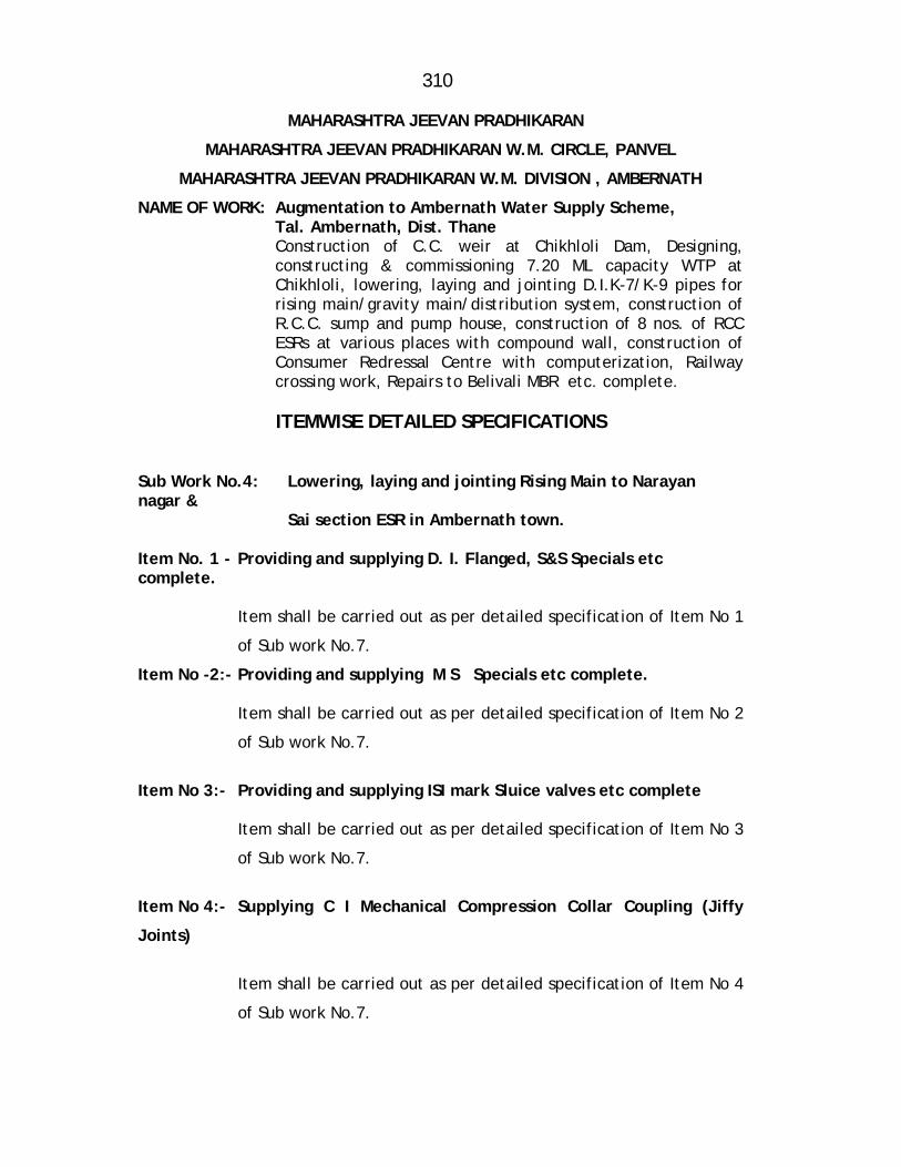
310
MAHARASHTRA JEEVAN PRADHIKARAN
MAHARASHTRA JEEVAN PRADHIKARAN W.M. CIRCLE, PANVEL
MAHARASHTRA JEEVAN PRADHIKARAN W.M. DIVISION , AMBERNATH
NAME OF WORK: Augmentation to Ambernath Water Supply Scheme, Tal. Ambernath, Dist. Thane Construction of C.C. weir at Chikhloli Dam, Designing,
constructing & commissioning 7.20 ML capacity WTP at Chikhloli, lowering, laying and jointing D.I.K-7/K-9 pipes for rising main/gravity main/distribution system, construction of R.C.C. sump and pump house, construction of 8 nos. of RCC ESRs at various places with compound wall, construction of Consumer Redressal Centre with computerization, Railway crossing work, Repairs to Belivali MBR etc. complete.
ITEMWISE DETAILED SPECIFICATIONS
Sub Work No.4: Lowering, laying and jointing Rising Main to Narayan nagar &
Sai section ESR in Ambernath town. Item No. 1 - Providing and supplying D. I. Flanged, S&S Specials etc complete.
Item shall be carried out as per detailed specification of Item No 1
of Sub work No.7.
Item No -2:- Providing and supplying M S Specials etc complete.
Item shall be carried out as per detailed specification of Item No 2
of Sub work No.7.
Item No 3:- Providing and supplying ISI mark Sluice valves etc complete
Item shall be carried out as per detailed specification of Item No 3
of Sub work No.7.
Item No 4:- Supplying C I Mechanical Compression Collar Coupling (Jiffy
Joints)
Item shall be carried out as per detailed specification of Item No 4
of Sub work No.7.
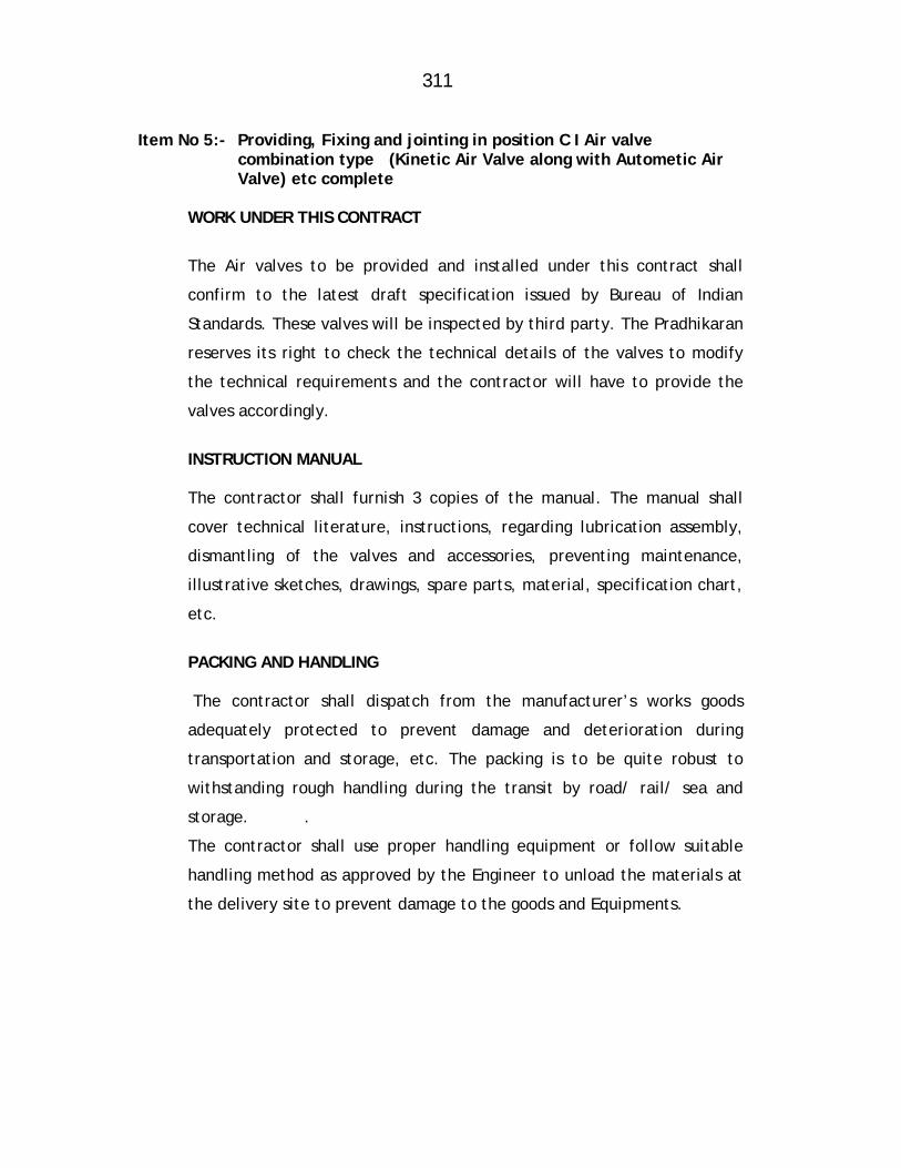
311
Item No 5:- Providing, Fixing and jointing in position C I Air valve
combination type (Kinetic Air Valve along with Autometic Air Valve) etc complete
WORK UNDER THIS CONTRACT
The Air valves to be provided and installed under this contract shall
confirm to the latest draft specification issued by Bureau of Indian
Standards. These valves will be inspected by third party. The Pradhikaran
reserves its right to check the technical details of the valves to modify
the technical requirements and the contractor will have to provide the
valves accordingly.
INSTRUCTION MANUAL
The contractor shall furnish 3 copies of the manual. The manual shall
cover technical literature, instructions, regarding lubrication assembly,
dismantling of the valves and accessories, preventing maintenance,
illustrative sketches, drawings, spare parts, material, specification chart,
etc.
PACKING AND HANDLING
The contractor shall dispatch from the manufacturer’s works goods
adequately protected to prevent damage and deterioration during
transportation and storage, etc. The packing is to be quite robust to
withstanding rough handling during the transit by road/ rail/ sea and
storage. .
The contractor shall use proper handling equipment or follow suitable
handling method as approved by the Engineer to unload the materials at
the delivery site to prevent damage to the goods and Equipments.
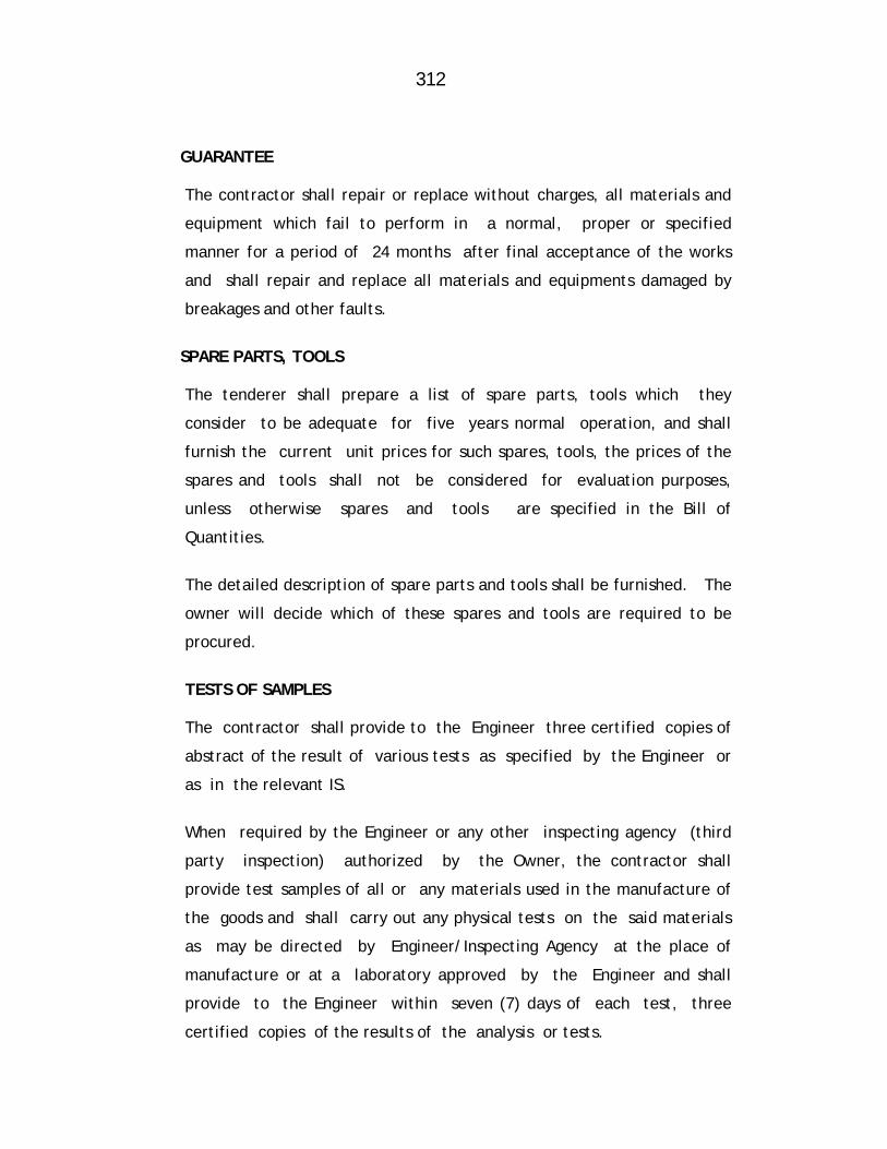
312
GUARANTEE
The contractor shall repair or replace without charges, all materials and
equipment which fail to perform in a normal, proper or specified
manner for a period of 24 months after final acceptance of the works
and shall repair and replace all materials and equipments damaged by
breakages and other faults.
SPARE PARTS, TOOLS
The tenderer shall prepare a list of spare parts, tools which they
consider to be adequate for five years normal operation, and shall
furnish the current unit prices for such spares, tools, the prices of the
spares and tools shall not be considered for evaluation purposes,
unless otherwise spares and tools are specified in the Bill of
Quantities.
The detailed description of spare parts and tools shall be furnished. The
owner will decide which of these spares and tools are required to be
procured.
TESTS OF SAMPLES
The contractor shall provide to the Engineer three certified copies of
abstract of the result of various tests as specified by the Engineer or
as in the relevant IS.
When required by the Engineer or any other inspecting agency (third
party inspection) authorized by the Owner, the contractor shall
provide test samples of all or any materials used in the manufacture of
the goods and shall carry out any physical tests on the said materials
as may be directed by Engineer/Inspecting Agency at the place of
manufacture or at a laboratory approved by the Engineer and shall
provide to the Engineer within seven (7) days of each test, three
certified copies of the results of the analysis or tests.

313
Approval by the Engineer as to the placing of orders for materials or
as to sample or tests shall not prejudice any of the owners rights under
the contract.
TEST CERTIFICATES
Certificates approved by the Executive Engineer of MJP in triplicate shall
be provided by the contractor for each complete item of the goods
supplied giving the process of manufacture and the results of the
specified tests. Similar certificate in triplicate shall be provided by the
contractor in respect of materials to be used in the manufacture of the
tools and the results of the specified tests.
INDEPENDENT AND LOCAL TESTS
The Engineer/Inspecting Agency, (third part inspection) reserves the
right to carry out any independent or local tests he/it may deem fit.
Any samples of materials which may be required for such tests shall be
provided by the Contractor at no extra cost to the Owner.
The cost of making any such independent tests shall be borne by the
Owner, unless it is shown that the workmanship or materials under
tests are not in accordance with the specifications in which case the
cost of the test shall be borne by the Contractor.
Any material, workmanship or completed items of goods, which are
shown by such independent tests to be not in accordance with the
specifications shall be rejected notwithstanding any previous certificate
which may have been provided.
All valves shall be tested hydraulically to test pressure as per
specifications in IS or 10 Kg/Sqcm, whichever is higher.
314
FIXING OF AIR VALVES
All types of Air valves required for work are to be supplied by the
contractor. The materials supplied shall be flanged as per requirement.
The valves are to be carted to the site from supply place, lowered in the
trenches and jointed to the pipe line as directed with cost of all jointing
materials, such as lead, rope, rubber packing, nut bolts, fire wood etc.
and the labour cost, which is included in the tender item. The joints may
be either screwed flanged or S/S lead joints depending upon the nature
of valves supplied and contractor shall have no extra claims of any
particular type of joint required to be done. The required number
jointing for fixing these valves is included in the tender item.
Mode of Measurement and Payment
The item will be measured and paid per number basis. 85% Payment shall
be released after supply and fixing of joints at site and 3rd party
inspection report and 15% after satisfactory hydraulic testing is
completed.
Item No.6 – Excavation for pipe trenches in average all types of strata of
earth, soil of all types, sand, gravel, soft murum, hard murum with boulders, soft rock, hard rock by mechanical chiseling & all means … etc. complete.
Item shall be carried out as per detailed specification of Item No 6
of Sub work No. 7.
Item No.7 – Filling in plinth and floors murum bedding in trenches etc. complete. Item shall be carried out as per detailed specification of Item No 7
of Sub work No. 7.
Item No.8 – Refilling the trenches etc. complete.
Item shall be carried out as per detailed specification of Item No
8 of Sub work No. 7.

315
Item No.9 - Providing and laying Plain cement concrete(M-15) ---etc
complete
Item shall be carried out as per detailed specification of Item No
9 of Sub work No. 7.
Item No.10 - Providing and laying Reinforced cement concrete (M-20) for thrust block/Anchor block ---etc complete
CONCRETE PROPORTION a) Proportions of concrete for types of work
M-200- RCC for footing, thrust blocks, anchor blocks, chairs and
encasing of pipes... etc.
b) General specifications of this work shall be as per standard
specification of Public Works Department, latest edition,
Section BdF-3 Page No 298.
c) Whenever concrete is to be laid in trenches, the trench shall be
cleaned, and watered before placing. The sub- soil water which is
met shall be removed and the trench shall be kept dry during and
after 2 hours of placing concrete.
d) The RCC designs for thrust block, anchor blocks, anti buoyancy
blocks, etc. shall have to be got approved from Engineer-in-
charge.
2. MODE OF MEASUREMENT AND PAYMENT The tender rate shall be for one cubic meter of concrete. The
concrete shall be measured for its length, breadth and depth
limiting dimensions to those specified in drawing or as per
direction of Engineer- in-Charge.
The damages to concrete during laying of pipe line shall be
rectified free of cost.
316
The rate for the concrete includes all labour, material,
centering, shuttering, curing etc. all leads and lifts.
10% amount will be withheld till satisfactory hydraulic testing is
given; mixing of concrete shall be done with concrete mixers.
a) The contractor will make his own arrangement for receiving
all material, tools etc. required for the work. b) No extra charges for the carriages of water will be allowed. c) The rates for all items are inclusive of all charges such as
carting, lifting etc.. No extra payment for any lead and lifts will be paid for any item.
d) The contractor should not be Sublette without written
permission of the Engineer-in-Charge.
Item No.11: Providing and fixing in position steel bar Reinforcement etc
complete
The item provides for supply of tor steel bars, cutting, bending,
binding with M.S. wire and placing in position, for reinforcement in
the RCC.
Tor steel bars shall confirmed to Specification Bd.F-17 Page No 306
of Standard Specification of Public Works Department latest
edition.
The binding wire shall confirm to Standard Specification of Public
Works Department latest edition.
Bending reinforcement shall confirm accurately to the dimensions
and shapes in the details drawings (approved) or as directed by the
Engineer-in-Charge.
Bars shall be bend cold only. In no way bending by heat will be
allowed. Bars with kinks, bends or cracks shall not be used.

317
Details of length, size, laps and bending diagram shall be got
approved by the Engineer-in-Charge.
As far as possible full lengths of bars shall be placed as per drawing
details. When full lengths are not available, bars are Splices only
after written permission of Engineer-in-charge. Splices shall be
staggered and in tension zone shall be avoided strictly. Bars shall
be lapped as specified in latest IS: 456 with due regards to the
grade of concrete.
All reinforcement shall be accurately placed in position with
spacing and cover shown in detailed drawing and firmly held
during the placing and setting of concrete. Bars shall be tied at
all intersections. Binding wire of 1.63mm or 1.2mm diameter
(about 16 or 18 gauge) shall be used. Spacing of the bars shall be
maintained by means of stays, blocks ties, spacers, intervals so
that bars will not be displaced during placing. Vibrating or
compacting concrete. Placing bars for reinforcement on a layer of
fresh concrete as the work progress will not be permitted. The
use of pieces of broken stones or bricks or wooden blocks for
Layers of bars shall be separated by precast cement blocks, spacer
bars or other devices.
Full details of numbers, sizes, lengths, weights, laps, welds, spacing
of bars placed in position in different parts of the work shall be
recorded by the contractor and certified and signed by the
Engineer-in-charge or his representative to show that all
reinforcement has been placed correctly as per sanctioned drawing
or has directed by the Engineer-in-charge in writing, before
placing concrete. No concrete shall be placed in position until
the Engineer or his representative has inspected and certified the
correctness of reinforcement, recording the steel measurements
and has given permission in writing to place concrete. After
318
approval of reinforcement as above, it will be the contractor's
responsibility to see that the spacing of reinforcement and
arrangements are not tampered with in any way before or during
concreting.
If the Contractor has to supply his own steel, he shall produce the
test certificate. In addition, actual test shall be carried out
according to IS:432:1966 in an approved laboratory and the cost
of test shall be borne by the contractor, including all transport
etc.
This Items Includes
Cost of labour, material, use of tools, plant and tackle and
other incidental items to complete the work satisfactorily.
Supplying, conveying, cleaning, cutting, bending, binding with
(1.63 mm or 1.22 mm diameter) (16 to 18 gauge) wire on spot,
welding and placing reinforcement in position and maintaining it
clean and in position till the concrete is laid.
Cost of sampling and testing, as required. In no case any foreign
material e.g. oil, grease, etc. Which prevent bonding between
steel and concrete shall remain on steel bars during placing of
concrete.
2. MODE OF MEASUREMENT AND PAYMENT The tender rate shall be on weight basis for MT of or steel
reinforcement. The weight of steel reinforcement used for the
item of concrete will be measured in metric tonnes based on
total compacted weight for the sizes and lengths of bars as
shown in drawing or as directed by Engineer-in-charge.
The lengths of the bars shall be measured correct to two places
of decimals of meters. The weights for payments shall be
319
calculated according to standard weights mentioned in the ISI
handbook correct up to 0.10 kg.
However, no extra claim for overweight of steel will be considered
for payment. Whether it is the contractors responsibility to bring
the steel as per standard weight.
Item No.12 – Lowering, laying & jointing DI S/S pipe etc. complete.
Item shall be carried out as per detailed specification of Item No
10 of Sub work No. 7.
Item No.13: Lowering, laying & jointing Sluice Valve etc. complete.
Item shall be carried out as per detailed specification of Item No
11 of Sub work No. 7
Item No.14:Providing 50mm thick full grout bituminous road surface etc.
complete.
Item shall be carried out as per detailed specification of Item No
13 of Sub work No. 7
Item No.15 – Providing constructing BB masonary Valve Chamber etc.
complete.
Item shall be carried out as per detailed specification of Item No
12 of Sub work No. 7
Item No.16 – Dewatering the excavated trenches etc. complete
Item shall be carried out as per detailed specification of Item No
15 of Sub work No. 7
Item No.17 – Disposing of surplus excavated materials etc. complete.
Item shall be carried out as per detailed specification of Item No
16 of Sub work No. 7
320
Item No.18– Cutting & chamfering of pipes etc. complete.
Item shall be carried out as per detailed specification of Item No
21 of Sub work No. 7
Item No.19: Providing & supplying rubber gaskets for DI pipes & Specials etc. complete. Item shall be carried out as per detailed specification of Item No
22 of Sub work No. 7
321
MAHARASHTRA JEEVAN PRADHIKARAN
MAHARASHTRA JEEVAN PRADHIKARAN W.M. CIRCLE, PANVEL
MAHARASHTRA JEEVAN PRADHIKARAN W.M. DIVISION , AMBERNATH
NAME OF WORK: Augmentation to Ambernath Water Supply Scheme, Tal. Ambernath, Dist. Thane Construction of C.C. weir at Chikhloli Dam, Designing,
constructing & commissioning 7.20 ML capacity WTP at Chikhloli, lowering, laying and jointing D.I.K-7/K-9 pipes for rising main/gravity main/distribution system, construction of R.C.C. sump and pump house, construction of 8 nos. of RCC ESRs at various places with compound wall, construction of Consumer Redressal Centre with computerization, Railway crossing work, Repairs to Belivali MBR etc. complete.
ITEMWISE DETAILED SPECIFICATIONS Sub Work No-5: Lowering, laying and jointing Transmission Main From Sai
MBR to Shivganga ESR in Ambernath town. Item No. 1 - Providing and supplying D. I. Flanged, S&S Specials etc complete.
Item shall be carried out as per detailed specification of Item No 1
of Sub work No.7.
Item No.2 - Providing and supplying M S Specials etc complete.
Item shall be carried out as per detailed specification of Item No 2
of Sub work No. 7.
Item No. 3:- Providing and supplying ISI mark Sluice valves etc complete
Item shall be carried out as per detailed specification of Item No 3
of Sub work No. 7.
Item No 4:- Supplying C I Mechanical Compression Collar Coupling (Jiffy
Joints)
Item shall be carried out as per detailed specification of Item No 4
of Sub work No.7.
322
Item No 5:- Providing , Fixing and jointing in position C I Air valve
combination type (Kinetic Air Valve along with Autometic Air Valve) etc complete
Item shall be carried out as per detailed specification of Item No 5
of Sub work No. 4.
Item No.6 – Excavation for pipe trenches in average all types of strata of
earth, soil of all types, sand, gravel, soft murum, hard murum with boulders, soft rock, hard rock by mechanical chiseling & all means … etc. complete.
Item shall be carried out as per detailed specification of Item No
6 of Sub work No. 7.
Item No.7 – Filling in plinth and floors murum bedding in trenches etc.
complete.
Item shall be carried out as per detailed specification of Item No 7
of
Sub work No. 7.
Item No.8 – Refilling the trenches etc. complete.
Item shall be carried out as per detailed specification of Item No
8 of Sub work No. 7.
Item No.9 - Providing and laying Plain cement concrete(M-15) ---etc
complete
Item shall be carried out as per detailed specification of Item No
9 of Sub work No. 7.
Item No.10 – Lowering, laying & jointing DI S/S pipe etc. complete.
Item shall be carried out as per detailed specification of Item No
10 of Sub work No. 7.
Item No.11 – Lowering, laying & jointing Sluice Valve etc. complete.
Item shall be carried out as per detailed specification of Item No
11 of Sub work No. 7
323
Item No.12 Providing constructing BB masonary Valve Chamber etc.
complete.
Item shall be carried out as per detailed specification of Item No
12 of Sub work No. 7
Item No.13 Providing 50mm thick full grout bituminous road surface etc. complete.
Item shall be carried out as per detailed specification of Item No
13 of Sub work No. 7
Item No.14 Making cross connection to existing distribution main etc.
complete
Item shall be carried out as per detailed specification of Item No
19 of Sub work No. 7
Item No.15 Dewatering the excavated trenches etc. complete
Item shall be carried out as per detailed specification of Item No
15 of Sub work No. 7
Item No.16 – Disposing of surplus excavated materials etc. complete.
Item shall be carried out as per detailed specification of Item No
16 of Sub work No. 7
Item No.17– Cutting & chamfering of pipes etc. complete.
Item shall be carried out as per detailed specification of Item No
21 of Sub work No. 7
Item No.18 – Providing & supplying rubber gaskets for DI pipes & Specials
etc. complete.
Item shall be carried out as per detailed specification of Item No
22 of Sub work No. 7
324
MAHARASHTRA JEEVAN PRADHIKARAN
MAHARASHTRA JEEVAN PRADHIKARAN W.M. CIRCLE, PANVEL
MAHARASHTRA JEEVAN PRADHIKARAN W.M. DIVISION , AMBERNATH
NAME OF WORK: Augmentation to Ambernath Water Supply Scheme, Tal. Ambernath, Dist. Thane
Construction of C.C. weir at Chikhloli Dam, Designing, constructing & commissioning 7.20 ML capacity WTP at Chikhloli, lowering, laying and jointing D.I.K-7/K-9 pipes for rising main/gravity main/distribution system, construction of R.C.C. sump and pump house, construction of 8 nos. of RCC ESRs at various places with compound wall, construction of Consumer Redressal Centre with computerization, Railway crossing work, Repairs to Belivali MBR etc. complete.
ITEMWISE DETAILED SPECIFICATIONS SUB WORK NO-6: CONSTRUCTION OF RCC ESR’S AT VARIOUS PLACES IN AMBERNATH TOWN Item No.1 – Designing, constructing R.C.C. E.S.R. etc. complete.
The Contractor shall quote his offer in Schedule ‘B’ for the complete
work of constructing R.C.C. E.S.R. to be carried out as per his own
design based on given data i.e. he shall tender the offer in Schedule ‘B’
for construction of required capacity with his own design and drawing.
The design shall be got checked from the institute like Govt. Engineering
College. Remarks shall be complied and scrutiny charges shall be borne
by the Contractor.
1. The reservoir will be a covered RCC container supported on RCC column
with footing and intermediate braces, etc.
2. Suitable M.S. ladders/spiral stair for ESR of capacity 2.00 lakh liters
with landing at regular intervals for approach to the gallery and top of
ESR shall be provided. For above 2.0 lakh liters capacity RCC spiral
case with parapet should be provided. RCC cantilever catwalk

325
(gallery) of 1.20 M width G.I. pipe railing shall be provided at floor level,
preferably at junction of floor slab and vertical walls.
Ventilators shall be provided on top slab of ESR. Four number of C.I. manhole frame and cover shall be provided and fixed
in the roof of tank and at catwalk way.
Two number of M.S. ladders shall be provided and fixed for access into
the tank through manhole left in the roof. Ladders shall be provided as
per specifications.
Water level indicator assembly of approved type shall be provided and
installed.
Lightening arrestor as per IS specifications and confirming to IE Rules
shall be provided and fixed.
Vertical and horizontal pipe of C.I. flanged pipes, M.S. /C.I. specials of
required sizes for inlet, outlet and overflow arrangements together with
suitable sluice valves shall be provided as per Schedule-B. For washout
one tee shall be fixed on the outlet pipe with one valve of suitable
diameter.
Sluice valves of required size shall be fixed for inlet, outlet and washout.
These valves shall be supplied by the contractor, confirming to relevant
ISS and of makes approved by Maharashtra Jeevan Pradhikaran.
Required number of B.B, masonry chambers of suitable size as directed
with RCC slab cover shall be provided and constructed at suitable
locations for sluice valves.
Water proof cement plaster of CM 1:3 proportion 20 mm thick shall be
provided for inside surface of the tank, including roof slab bottom.
326
Epoxy paint shall be provided for inside surface of the tank, including
roof slab, bottom slab, vertical wall, internal column and beam.
Out side surface of tank, exposed faces columns, braces, catwalk bottom
portion of slab and exposed surface of the tank shall be provided with
smooth finish and then 3 coats of approved shade of snowcem paint as
per colour scheme approved by the Maharashtra Jeevan Pradhikaran shall
be rendered.
Letters indicating capacity of tank, name of scheme and year of
construction shall be either embossed or engraved on vertical wall of
tank and shall be painted with suitable shade of oil paint in 2 coats.
On completion of work hydraulic test or water tightness test shall be
given as per standard specification. Therefore, required water
arrangements shall be made by contractor at his own cost.
Since this is lump-sum offer, the interim payments will be make at
different stages of works contract, as per break-up schedule enclosed.
Since this is water retaining structure, contractor shall give a satisfactory
hydraulic test of the tank. This test shall be considered as water
tightness test and accepted if the structure appears bone dry from
outside after filling with water upto full supply level and the drop in
water level is not more than 40 mm in 7 days. For this purpose the water
filling arrangements shall be made by the contractor at his own cost,
including cost of water pumping arrangements etc.
If during testing any damage occurs to the structure, it will be the
responsibility of the contractor to rectify the same.
327
EXCAVATION:-
Excavation for foundation in earth, soil of all types, sand, grave, soft
murum, hard murum, with boulders, soft rock, hard rock by chiseling etc.
complete.
The excavation shall be done as per standard specifications No. Bd-A1,
A2A3,A4,A5 and A6 page No.271-272 of 1965 or as per latest edition of
the Standard specifications.
The excavation shall be done to the required depth and section. Extra
excavation done for whatever reasons shall not be paid for under any
circumstances. The excavated material shall not be placed nearer than
5.0 meter, from edges of excavated trenches.
Necessary shoring and strutting of sufficient strength should be provided
to sides of excavation to prevent caving in. The bottom of excavation
shall be leveled both longitudinally and transversely or stepped.
Removing the excavated materials of all categories including loading,
conveying, unloading, spreading or stacking including all leads and lifts
etc. complete. Surplus excavated materials is the property of MJP and
therefore contractor is not empowered to sell this excavated material to
any other agency.
Dewatering the excavated trenches and pools of water in construction
area by using pumps and other devices, including disposing of the water
to a safe distance as directed.
MATERIALS REQUIRED FOR CONSTRUCTION 5. Sand, Metal and Bricks
Sand, metal and bricks of best quality. will be insisted. Samples of these
will have to be got approved prior to use on work from Engineer-in-
Charge.
328
6. Cement
L & T/Ambuja/ACC/Birla Gold brand of 43 grade in jute/polyethylene
bags (weighing 50 Kg each) shall be used for all water retaining
structures.
7. Reinforcement
The steel to be used shall be grade Fe.415 as per design. The contractor
shall have to procure the steel from open market. The steel procured by
contractor shall be tested and the contractor shall produce
manufacturer’s test certificate without which it shall not be accepted.
Further the contractor shall arrange to get tested any samples from steel
brought at site by him in laboratory at his cost and result should be
submitted to the Maharashtra Jeevan Pradhikaran. The reinforcement is
to be provided with Fusion Bonded Epoxy paint. Defective steel brought
by contractor shall be rejected and will not be allowed to be used. Test
certificate stating the chemical composition and characteristics of the
product.
At least 3 samples of each diameter should be tested from every 5 ton or
part thereof. Tested lots only will be permitted to be used.
8. Concrete
The PCC and RCC works shall be as per IS 456-2000. Concrete mixer shall be used for preparing concrete. Vibrator shall be used to consolidate concrete while placing in position.
While concreting, respective samples in form of test cubes shall be taken
by the contractor under Maharashtra Jeevan Pradhikaran Supervisor and
shall be tested under his supervision. Charges of testing shall be borne
by the contractor and will be recovered from bills payable to him.
329
9. Water Level Indicator Assembly
Water level indicator assembly comprising of float, pulleys, non
extensible chord of required length, indicator arm, enameled gauge
board to represent depth of water in tank to full scale etc. shall be
provided and fixed by the contractor as per direction of Maharashtra
Jeevan Pradhikaran. The gauge board comprising of M.S. angles/channels
shall be fixed to exterior face of column at about 5 m above ground level
at site. The chord at vertical wall face shall be enclosed in G.I. pipe for
a height of 2 m above floor level of gallery. The ball should be of
suitable martial so as to float on water. The level indicator shall be as
per directives of Engineer-in-Charge.
10. Lightening Arrestor
Lightening arrestor conforming to IS and Indian Electrical Rules shall be
provided. The lower most portion of tape for 2 meters above ground
levels and 2 meters below ground level shall be enclosed by 50 mm G.I.
pipes medium class. An arrangement such as construction of column over
roof slab etc. shall be made in order to achieve full coverage of structure
against lightening.
11. Pipe Railing at Free End of Catwalk
Railing shall be of G.I. pipes ‘B’ class not less than 25 mm diameter in the
2 rows and shall be fixed in position to RCC posts or M.S. angle posts of
size 65 x 65 x 6 mm x 1 M in height, located at a maximum distance of 1
M c/c. The railing and the posts shall be provided with 2 coats of oil
paint of approved shade.
12. M.S. Ladder
Two numbers of M.S. ladder shall be provided and fixed to give
access into the tank through manhole in the roof slab. The ladder
shall be comprising of M.S. approved section placed at 45 cm, apart
330
with M.S. Bars of approved dia. in double rows as steps at 20 cm c/c.
The ladder shall be encased by C.C. at both the ends.
13. Centering Work
Before starting the work of ESR, the contractor should submit design
of centering and its detailed drawings for approval by Maharashtra
Jeevan Pradhikaran. This set of drawing shall be kept at site.
Erecting, laying and fixing in position CIDF pipes and specials for Inlet, Outlet, Washout, Overflow etc.
The item includes erecting, fixing, laying and jointing pipes and
specials for inlet, outlet, washout, overflows etc. as described in
tender item. The pipe and the specials of any category are to be
erected and joined under ground or above either in horizontal or
vertical or inclined direction as per requirement with all leads and
lifts involved in the work. The erecting shall be in perfect line and
level. Necessary supporting girders, ropes, chain-pulley etc., if
required shall be arranged by the Contractor at his own cost.
The item includes all labour and materials for jointing such as lead,
nuts and bolts, rubber packing etc. The materials for jointing shall be
procured by the Contractor from open market at his own cost. The
tendered rate includes both lead and flanged joints depending upon
the nature of pipes and specials and no extra claims for any
modifications, increase or decrease in joints the standard lead
consumption for lead shall be as per specifications of item of pipe line
works.
The cost involved in fixing pipes and specials in walls etc. together
with leak proof arrangement thereof required is included in the
tendered rate and no extra claims for any provision required shall be
entertained.

331
Satisfactory hydraulic test shall be given by the Contractor at his cost
which is included in the tender item. During testing, if any joints are
found leaky they shall be repaired at the Contractor's cost.
Pipes if found leaky, cracked, during testing they shall be removed,
replaced re-fixed and jointed with good pipe and specials.
Two coats of epoxy paint shall be given to the pipes and specials above
ground and cost thereof is included in the tender item. The job shall also
include laying of pipes and specials up to ground, sluice valves for inlet,
outlet, washout, overflow etc. and their interconnection etc. as required
and directed by the Engineer-in-Charge.
DESIGNING, PROVIDING AND CONSTRUCTING RCC ESRs
Special conditions for construction of ESR
Specification and design criteria for RCC ESR with Contractor’s own design.
1. Material a) Cement Only 43 grade cement shall be
used, 53 grade cement is not recommended. Super plasticizer in the proportion of 0.5% (0.25 Kg/Cement bag) should be used
b) Steel “Fe-415” CTD bars, conforming to
IS:1786:1995 shall be used. The reinforcement are to be provided with Fusion Bonded Epoxy paint. The minimum dia of reinforcing bars shall be 10 mm.
c) Centering Centering should be designed by
the Contractor. Same should be approved by the competent authority before construction, only
332
steel/plywood centering shall be used.
d) Mix concrete Following concrete grades should be
used for various component of ESR. 1. Container M-300 2. Staging M-300 3. Foundation M-300 4. PCC M-200
2. Designing, providing and constructing RCC ESR
General Note
2.1 The contractor shall quote his offer in Schedule ‘B’ for the complete
work of constructing RCC ESR /GSR/Sump Pump House to be carried out
as per his own design based on given data i.e. he shall tender the offer in
Schedule ‘B’ for construction of elevated tank of required capacity
including fixing pipes, specials, valves and providing and fixing, lighting
conductor, CI manhole frame and cover, water level indicator, ventilator,
etc. complete with his own design and drawings. The design shall be got
checked from the institutes like Govt. Engineering College. Remarks
shall be complied and scrutiny charges shall be borne by the contractor.
2.2 The contractor shall submit the name, qualifications and experience of
Design Engineer who has prepared detailed RCC calculations or who will
prepare design and drawings on acceptance of the tender. The
authorized representative of the designer will have to inspect and certify
the works at foundation level and every beam level.
2.3 The Design Engineer has to prepare and submit a note on design
methodology and construction and drawings in 2 copies through the
contractor.
The note should indicate general description and salient features of the
design covering the following points.

333
1) Capacity 2) Shape and type
3) Staging height of tank indicating various levels
4) Safe bearing capacity assumed in the design of safe bearing
capacity of strata based on actual investigation report of
laboratory and type of foundation provided with proper
justification.
5) Maximum and minimum subsoil water level.
6) Site plan showing location of ESR
7) Line diagram showing dimensional and sectional elevation with
important levels.
8) Design parameters proposed to be adopted for detailed design.
2.4 This note on design will be subjected to thorough check by the Engineer-
in-charge of the owner and the tender will be accepted and work order
issued by the competent authority only after verification that the design
to be offered will fulfill the requirements of the design as per tender
specifications.
2.5 After acceptance of tender, the contractor will have to submit 3 copies
of detailed design and drawings of the structure within 15 days of
acceptance of the tender.
2.6 The design engineer will be required to attend the office of Engineer-in-
charge for preliminary discussion for scrutiny remarks, etc. whenever
required with all reference data, books, IS specifications, etc. at his own
cost.
334
2.7 It will binding on the design engineer of contractor to clarify, modify,
redesign and prepare drawing after compliance of scrutiny remarks
by the owner or his representative such as an Engineering College,
within 15 days of communication of remarks. Owner will approve
Even though design; it will be the entire responsibility of Design
Engineer and the contractor.
2.8 On approval of the design, contractor shall supply, free of cost, 8
sets of design and drawing duly bound for use of the owner. The
contractor shall also furnish the details of steel requirement along
with program of execution for completion of work within the time
limit stipulated in the tender.
2.9 Security deposit of the tenderer shall be forfeited if he fails to
modify his design as per scrutiny remarks within specified time after
levy of compensation as per tender agreement.
2.10 Even though the design and drawing submitted by the contractor are
approved by the Owner/Engineer-in-charge, the contractor will not
be relieved of his contractual obligations to hand over the structure
in sound condition, duly tested.
2.11 In case of any damage/failure either during construction, testing or
after commissioning whether due to faulty design or defective
construction, all repairs or reconstruction of the structure shall have
to be carried out by the contractor, entirely at his risk and cost. No
claim for such repairs/reconstruction shall be entertained.
Design Conditions
The contractor can alternatively quote with his own design with
following conditions.
335
1. The design of RCC ESR shall be carried out by a designer having
minimum qualification of graduation in Civil Engineering/Structural
Engineering. He shall sign the design and affix his name and stamp.
2. The design shall be carried out in conformity with following IS code
(latest edition).
a) IS 456-2000
b) IS 3370-Part I & IV
c) IS 875
d) IS 11682
e) IS 1893 with inclusion of seismic zones as per latest circular
f) IS 1786 for cold worked steel grade deformed bars
(Tor steel of 415 grade and mild steel grade I shall only be used)
g) IS 13920-1993 for ductile detailing, applicable for ESRs under
seismic zone III, IV and V. (recent editions of IS shall be referred)
h) B.S.I. publication S.P. 34 (S & T) 1987.
3. Foundation for ESR The foundation should have the required safe bearing capacity. Minimum
depth of foundation shall be satisfy the following criterion.
a) Depth of soft rock shall not be less than 1 m or depth in hard rock
shall not be less than 0.5 m.
b) The total depth in all strata put together shall not be less than 2.50 m.
In B.C. soil, raft shall be provided at minimum depth of 3 m. No extra
payment shall be given to the contractor on increase in depth of
foundation.

336
4. The free board shall be include in the depth of water for design purpose.
5. Minimum free board shall be 300 mm, measured below bottom of roof
beam, 6. Maximum actual water depth shall not exceed 5.0 M. 7. Clear cover for reinforcement shall be provided as below
a. Footing 50 mm at bottom & sides
40 mm at top
b. Columns 40 mm c. Braces, beams, slab,
vertical wall, gallery Note:- For container minimum cover to the main reinforcement shall not be less than 45 mm.
8. Minimum thickness of container member shall be as below: a) Bottom slab and vertical wall 200 mm
b) Roof slab 120 mm 9. All members of container should be designed as “un-cracked section” as
per IS:3370.
10. The design of container members which includes bottom and roof beams,
bottom slab, roof slab, vertical wall and gallery shall be done in M-300
grade of concrete and casting should be done in M-300.
11. The staging of ESR (columns, braces, footing/raft) shall be designed in M-
250 grade of concrete however casting shall be done in M-300 grade of
concrete.
12. The staging shall be designed for ductile detailing as per IS 13920-1993,
wherever applicable.
337
13. Columns should be design by “working stress method” and as per IS:456.
It can be checked by limit state method IS:11682:1985 should be followed
for design of staging.
14. The width of braces shall be maximum of the following in case of Earth
Quake Zone III and above.
a) 250 mm for Earth Quake Zone III and above or
b) 75% of column side (column dia in case of circular column) 15. Width to depth ratio in case of braces shall preferably be more than 0.30.
16. Increase in permissible stress in braces for earth quake/wind force design
will not be allowed.
17. The center to center distance between braces shall not exceed 4.50 m
c/c for ESR having capacity up to 500 Cum and not more than 6 m c/c for
ESRs having capacity above 500 Cum at the joint of brace and column the
links to the column bars shall be tied properly and this shall be
thoroughly checked before concreting.
18. Wherever annual raft is provided, the inside and outside dia of raft shall
be designed in such a way that the center of gravity of upward reaction
co-inside with center of columns/raft beam center.
19. Uplift pressure on the foundation shall be considered as per water table
at site in rainy season. However, minimum uplift up to 50% of depth of
foundation below ground level shall be considered in the designs.
20. 20 mm thick cement plaster with CM 1:3 proportion with waterproof
compound shall be provided to the container from inside (including roof
beams and roof slabs/dome, etc.)
338
21. The shape of container may be circular. Similarly the column shape may
also be square or circular.
22. Minimum diameter of column should be 400 mm for staging and 200 mm
for column inside container
23. Minimum dia of main bars in the footing bottom slab and vertical walls
shall be 10 mm and minimum clear distance between reinforcing bars
shall not be more than 180 mm.
24. Water density shall be taken as 1000 Kg/Cum and live load on gallery
shall be considered as 300 Kg/Sqm. Minimum load of waterproof
treatment on roof slabs shall be taken as 100 Kg/Sqm.
25. The diameter, weight per meter tensile strength and minimum elongation
properties of steel brought by the contractor/supplied by the Department
shall be got tested from the approved laboratory before its use. Fusion
Bonded Epoxy painted , Steel shall be used only when the test report
indicated that the steel is in accordance with the IS Specification and
design presumptions.
26. Foundation 1. All columns shall have the same foundation level, as far as possible
in any case the foundation level difference between any two
columns shall not exceed 1.50 m. In such case “Sway analysis” of
the staging shall be done and additional reinforcement or increase
in the size shall be provided, if necessary.
2. When safe bearing capacity of foundation level is less than 15
T/Sqmt only raft foundation should be provided.
339
27. General
a) The inlet, outlet, overflow and bye-pass piping shall be provided as
below.
The vertical pipe assembly and horizontal pipe line from duck foot
bend of vertical pipe up to a distance of 8 m beyond external face
of nearest column and any parts arrangement shall be in cast iron
double flanged pipe/M.S. welded pipes, minimum thickness of M.S.
pipes shall be 10 mm.
b) Overflow arrangement shall be from top to bottom as vertical pipe
assembly with proper drainage arrangement.
c) For all duck foot bends for inlet, outlet and overflow arrangements
individual columns with footing resting at foundation level of
column of ESR columns/raft shall be provided.
d) The manhole frame and covers provided in the roof slab shall be of
cast iron only.
The above 4 conditions i.e. 27(a), 27(b), 27(c) & 27(d) shall be
followed without substitutes and equals No. M.S. piping and spout
type overflow arrangement shall not be accepted, even if rebates
etc. are offered.
e) Inlet, outlet, bye-pass and scour valves with chambers shall be
provided. The horizontal piping for inlet, outlet, overflow, bye-
pass up to 8 M from outer brace shall be provided and laid without
any extra cost.
f) Lightening conductor, water level indicator, central ventilator and
M.S. ladders, RCC staircase shall be provided as per Departmental
Specifications.
340
28. The design submitted by the contractor shall be checked from the
nearest Government Engineering College for which the scrutiny charges
shall be borne by the contractor. The delay in checking designs from
third party as above shall be treated as the delay on the part of
contractor for operation of tender clauses.
29. Size of inlet, outlet, overflow, bye-pass piping and valves including scour
valve shall be specified as per actual requirements and makes of valves
shall also be specified list of MJP.
30. Capacity of the container of the tank shall be the volume of the water it
can store between the designed full supply level and the lowest supply
level.
31. Height of staging shall be the vertical difference between lowest supply
level and the average G.L. at the site of tank.
32. Rectification of Defective Members
If it is found that certain members are defective and are found giving
acoustical or vibrations disturbance even though these may by
structurally sound, rectification of such members should be done by the
contractor free of charge and to the satisfaction of Engineer-in-charge.
33. Access to various levels of Reservoir 1. Spiral Staircase A RCC pre-cast step spiral staircase, one meter wide from ground
level to bottom slab level gallery to roof slab level of RCC ESR with
intermediate platforms and sufficient number of stiffeners at
intermediate levels and with proper landing and railing be
provided for the spiral staircase.

341
A M.S. grill gate of 2.0 m height with locking arrangement of
approved design shall be provided and fixed by the contractor as
directed.
34. Ancillaries
Providing and fixing G.I. Hand Railing
Railing of roof of service reservoir and bottom gallery shall be of medium
class G.I. pipes conforming to IS:1239 (medium) for 25 mm dia in three
rows and shall be fixed in position in RCC post 150 x 150 mm at bottom
and 100 x 100 mm or M.S. angle posts of size 65 x 65 x 6 mm of one meter
height and spaced at 1.50 m center to center. The railing painted with
one coat of primer two coats with approved shade of snowcem. Work
shall be carried out as per standard specifications Sr. No. 5(b) Page No.
145. If dome is provided at roof level, contractor has to provide 1.20
wide horizontal slab for walkway along periphery railing shall be provided
around walkway.
35. Providing and fixing water level indicator
Providing fixing in position water level indicator on column with
M.S. Clamps and as per standard specifications including M.S.
enameled guage plate 150 mm wide, 3mm thick, copper float,
providing and fixing required accessories such as pointer, pulleys,
nylon thread, with painting on gauge, figure of with appropriate
size etc complete and as directed by Engineer-in-charge.
36. Ventilators
Adequate shaft type ventilators shall be provided. It shall be minimum
1.0 meter in diameter and 1.5 M height shall be closed by mosquito proof
double mesh net fixed in wooden frame screwed to RCC columns of
suitable size.
37. Lightening Arrestor

342
Providing and fixing in position lightening conductor as per standard
specification and Indian Electricity Rules including copper rod of 20 mm
dia upper terminal 1.5 m long with a knob at the end, with a conical
spike at top with copper tape conductor, 20 mm x3 mm size copper earth
plate 3mm thick and 0.81 sqm. In area with clamps at 1.00 m c/c
including necessary excavation, laying and fixing the conductor including
charcoal salt filling, refilling, water etc complete.
This shall be taken through G. I. Pipe of 40 mm dia. (medium class) by
the side of column G. I. Pipe should be fixed with clamps. The length of
G.I. pipe should not be less than 3.00 meter above the average ground
level and above 0.5 m below G.L.. This arrangement is required for safety
of lightening conductor, Aluminum tape of equivalent section should not
be allowed. Lightening conductor shall be provided one number per 500
sqm of surface area
38. B.B. Masonry Chambers
Providing and constructing six numbers of brick masonry chambers of
suitable size with B.B. masonry in cm 1:6,1:3:6 cement concrete of 0.15
m thick in foundation, finishing etc complete, 12 mm thick cement
plaster in cm 1:3 from inside and outside. Providing and fixing in position
necessary numbers of M.S. steps and precast R.C.C. cover Depth. Of
chambers etc are as per actual layout of pipeline.
39. Providing and fixing C.I. manhole frame and Cover
Two numbers of CI manhole frame and covers (light type) of size 90 cm x
60 cm, weighing not less than 50 Kg. Each set with locking arrangement
be provided for access into the tank. The cover and frame is to be
painted with two coats of anticorrosive paint. The locking arrangement
shall be hinge type flat with eye.
343
40. Snowcem Painting (From outside and epoxy painting from inside)
As per BD 0-8 (page 391) the work will be carried out by cement based
‘Snowcem’ paint. Three coats shall be applied. The colour shed shall be
got approved from the competent authority. The paint shall be cured
sufficiently by making sprinkling arrangement. Providing and applying
special epoxy paint of standard approved make in two coats to the inside
surface of the container, roof / floor slab and inside column, including
necessary scaffolding etc complete as directed.
41. Painting of E.S.R.
Marathi and English letters of suitable size will be painted with best
quality paint to the satisfaction of Engineer-in-charge indicating Name
and capacity of reservoir.
42. CI/DF Pipe Laying Works
The pipe line being laid under this contract is below and above ground.
For pipe line portion to be laid above ground the pipe line shall be
supported on concrete chairs. Indicative longitudinal section of the pipe
lines has been shown on the drawings accompanying this contract. The
supports shall be casted to the true alignment and/or levels as per
detailed drawing prepared while laying. The Engineer may make
modifications in the alignment and/or levels at his discretion, depending
on the site conditions.
43. Fixing Different Valves
A) The valves shall be brought by contractor. This item includes
fixing of valves at site of work including cost of transportation,
loading and unloading, etc. all materials and labours required for
fixing including testing. The size of nuts, bolts and packing shall
be as per IS Specifications and suitable

344
for the type to valves and as per the direction of Engineer-in-
charge. The location of the valves shall be decided by the
Engineer-in-charge.
B) Appurtenance
1) Appurtenance such as sluice valves shall be supplied by the
contractor. The contractor shall transport them to the site and fix
them at the place as shown on the drawings or as directed by the
Engineer-in-charge.
2) Before any of the valves are fixed at the predetermined position,
these shall be cleaned, greased and it shall be checked that these
are in proper working condition. The valves shall be fixed in true
plumb and level. Sluice valves shall be properly supported on
wooden sleepers till the Anchor Block casted sets.
44. Disposing Off Surplus Excavated Material
The surplus excavated stuff shall be disposed off by mechanical means
beyond 50 meter and upto 5 Kms lead as directed by Engineer-in-charge.
45. Providing and Placing Cement Concrete
a) The specification contained in the Standard Specification Volume II Published by Public Works and Housing Department, Government of Maharashtra, Chapter Bd-F-1 to F-2 and Bd-E-1 shall apply.
b) This work shall be done in accordance with IS:456:2000 (revised) c) Proper curing be done for 21 days.
TEST PROCEDURE ( IS:516:1959 CLAUSE 5.5)
Specimen stored in water shall be tested immediately on removal from
water and while those are still in the wet condition. Surface water and
grit shall be wiped off the specimens and any projecting fins removed.
Specimen, when received dry, shall be kept in water for 24 hours before
345
taken for testing. The dimensions of the specimen to the nearest 0.2 mm
and also weight shall be noted before testing.
Requirement of Materials 1. Cement shall be Ordinary Portland Cement
The measurement of proportion of cement should normally be on the
basis of weight and whole bags, each undisturbed and sealed 50 Kg bag
being considered equivalent to 35 liters (1.2 Cuft.) in volume. When part
bag is required, cement shall be taken by weight. Care should be taken to
see that each bag contains full quantity of cement.
Tests
When tests are considered necessary, they shall be carried out as
indicated in IS : 269. The contractor should ensure that the cement is of
sound and required quality before using
2 Storage
Cement required for use shall be as fresh as possible and stored on planks
raised 15 to 20 cms ( about 6” to 8”) above the floor and stacked 30 cm (
about 12” ) away from the walls in suitable closed weather proof
buildings at the work site or at the selected approved site, in such a
manner as to prevent deterioration by dampness or moist atmosphere or
instruction of foreign matter..)
2.1 Any cement which has deteriorated baked or which has been damaged
shall not be used. Cement that is condemned shall be immediately
removed from the work site.. Ordinary cement stored for more than 2
months from the date of receipt from the factory shall be subjected to
test and used only if found satisfactory.. Cement shall be kept in a store
under double locking arrangement so that it can be taken out or fresh
stock admitted with the knowledge of supervising staff of the
Department.
346
3.0 WATER 3.1 Water for mixing cement / lime mortar or cement / lime concrete shall
not be salty or brackish and shall be clean, reasonably clear and free
from objectionable quantities of silt and tracers of oil, acid injurious
alkali, salts, organic matter and other detritus material which will either
waken the mortar or concrete or cause efflorescence or attack the steel
in RCC. Water shall be obtained from sources approved by the Engineer.
3.2 Water for curing cement / lime mortar of concrete
Water for curing mortar or concrete should not be too acidic or too
alkaline. It should a have a pH value ranging between 4.5 to 8.5. It shall
be free of element which significantly affect the hydration reaction or
otherwise interfere with the hardening of mortar of concrete during
curing
Portable water will be generally be found suitable for curing cement /
lime mortar or concrete.
4.0 FINE AGGREGATE (SAND) General
All fine aggregate shall conform to IS: 383 ( latest edition) and relevant
portion of IS:515 (latest edition ) directed by the Engineer.
Sand for use in concrete work shall be natural sand shall be clean well
graded, hard, strong durable and gritty particles free from injurious
amounts of dust, clay, kankar, nodules, soft or flaky particles, shale,
alkali, salt organic matter, lam, mica or there detritus substances and
shall be approved by the Engineer. The maximum size of particles shall
be limited to 5 mm ( about 3/16”). Organic impurities and other detritus
substances as laid down in Is :383 ( latest edition). It shall not contain
detritus materials
The fine aggregate for cement mortar for masonry and first coat of
plaster should generally satisfy the following grading.
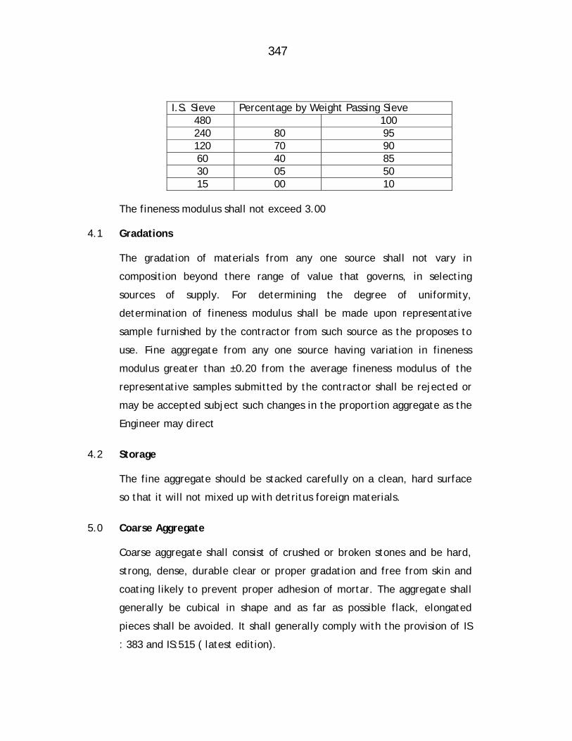
347
I.S. Sieve Percentage by Weight Passing Sieve
480 100 240 80 95 120 70 90 60 40 85 30 05 50 15 00 10
The fineness modulus shall not exceed 3.00 4.1 Gradations
The gradation of materials from any one source shall not vary in
composition beyond there range of value that governs, in selecting
sources of supply. For determining the degree of uniformity,
determination of fineness modulus shall be made upon representative
sample furnished by the contractor from such source as the proposes to
use. Fine aggregate from any one source having variation in fineness
modulus greater than ±0.20 from the average fineness modulus of the
representative samples submitted by the contractor shall be rejected or
may be accepted subject such changes in the proportion aggregate as the
Engineer may direct
4.2 Storage
The fine aggregate should be stacked carefully on a clean, hard surface
so that it will not mixed up with detritus foreign materials.
5.0 Coarse Aggregate
Coarse aggregate shall consist of crushed or broken stones and be hard,
strong, dense, durable clear or proper gradation and free from skin and
coating likely to prevent proper adhesion of mortar. The aggregate shall
generally be cubical in shape and as far as possible flack, elongated
pieces shall be avoided. It shall generally comply with the provision of IS
: 383 and IS:515 ( latest edition).
348
The maximum size of the aggregate may be up to 20 mm and well graded
between the sixes 5 mm to 20mm in such proportions as to give maximum
density to the concrete. The maximum size should be as large as possible
within the above limit but should not exceed ¼ of the minimum thickness
of the member provided, however, this size present no difficulty in the
case of RCC to surround the reinforcement thoroughly and fill up the
corners of the form work satisfactorily. In the case of general concrete
work, a maximum size of 40 mm ( about 1/22’ ) is used and in RCC work a
maximum size of 20 mm (about 1 ¼”) will be found satisfactory, but it
should be restricted to 6 mm ( about ¼”) less than the minimum lateral
clear distance between bars or 6 mm ( about ¼”) less than the cover,
whichever is smaller.
The crushing strength of aggregate will be such as to allow the concrete
in which it is used to build up the specified strength of concrete.
Approximate range, in grading of coarse aggregate may be as required.
Grading tests shall be in the beginning and at change of surface of
machinery or type of metal. Where required by the Engineer, tests
indicated in IS: 368 and IS: 456 (latest edition) shall be got carried out in
an approved laboratory at the contractor’s cost to show the acceptability
of the material.
Coarse aggregate of a porous nature where absorption of water after 24
hours immersion in water, is more than 5 percent by weight, shall not be
used
Limit of deleterious substance shall not exceed those prescribed in IS :
515 ( latest edition)
349
5.1 Storage
The aggregate of different sizes shall be stored separately and
handled in such manner as to prevent intermixing of different sizes of
aggregate required separately for grading purposes. No foreign matter
shall be allowed to be mixed up with aggregated. If covered with dust
etc. they shall be washed clean before use.
6.0 MIXING
For all important woks concrete shall be mixed in mechanical mixer at
the site of work. Care shall be taken to see that the mixer or other
accessories are in first class working condition and maintained so
throughout the construction. Mixing shall be continued till there is
uniform colour is obtained and each individual article of the coarse
aggregate shall show a complete coating of mortar contain in its
proportionate amount of cement. In no case mixing shall be done for
less than 1 ½ minutes.
6.1 When hand mixing is permitted by the Engineer it shall be done on a
smooth water tight platform large enough to allow efficient turning
over of the ingredient of concrete before and after adding water.
Mixing platform shall be so arranged that no foreign materials shall be
get mixed with water & shall not be flow out.
6.2 The cement of required number of bags shall be placed in a uniform
layer on top of the measure quantity of fine aggregate required, also
spread in a layer of uniforms depth in the mixing platform. Dry sand
and cement shall then be mixed thoroughly by turning over to get a
mixture of uniform colour. Enough water then be added gradually
through a rose and the mass turned over till a mortar of required
consistency is obtained. The measured quantity of coarse aggregate
shall then be placed on the mixing platform and wetted and the
mortar added and the entire mss turned and returned until all the
particles of the coarse aggregate are fully covered with
350
mortar and the mixture is of a uniform colour and required
consistency. In hand mixing quantity of cement shall be increased by
5% above the specified
6.3 Concrete shall have a consistency such that it will be workable in the
required position and in the case of RCC flow around reinforcing steel
also.
6.4 For vibrated concrete slump shall range between 2.5 to 5 cm ( about 1 “
to 2”) For hand tamped concrete, slump shall range between 8 cm to 13
cm ) 3” t 5” according to the type and nature of the concrete item. The
sump shall be the latest permitted by workability. The slump shall be
determined as detailed in relevant IS code provisions and maintained
throughout the concreting operation of a member.
The concrete shall be placed n its final position and rammed, vibrated
and finished within 30 minutes of adding water to cement. Re-tempering
or remixing of partially hardened concrete shall not permit. Mixing shall
be done only by mechanical mixer
6.5 Transporting
The concrete shall be handled from the place of mixing to the final
position as quickly as practicable by methods which will prevent
segregation and loss of ingredients. In no case shall the operation take
more than 15 minutes
6.6 Placing
The concrete shall be placed into its final position, compacted and
finished within 30 minutes of mixing the water and before setting
commences. The method of placing shall be such as to avoid segregation.
351
Placing shall be done in balanced manner to avoid eccentric loads on
form work.
As far as practicable the concrete for particular portion shall be done in
one continuous operation. The construction joints when required shall
made only where located on the plans or shown in the pouring schedule
unless otherwise approved by the Engineer. The joint shall be vertical
and shall be made by placing a bulk head at the joint. Before
commencing subsequent concreting, all loose particles, laitance etc. shall
be removed and the surface shall then be covered by thick cement slurry
as part of placement. Care shall be taken during the placing not to
disturb the forms or the reinforcement. Concrete compacted manually,
shall preferably be laid in layers of 51 cm to 20 cm ( about 6“ to 8”) the
layers being decided by the time lapse between the successive layers.
The time of laying one layer shall not exceed 30 minutes. The successive
layers shall commence within 30 minutes of laying first layer.
When work is to be resumed on a surface which has hardened, such a
surface shall be roughened and scrubbed with brushes to remove
laitance, care being taken to avoid dislodgment of coarse aggregate,
swept clean thoroughly wetted and covered with 6 mm (about 1”) thick
mortar layer composed of cement ad sand in the same proportion as the
cement and sand in the concrete for securing good bond.
The concrete shall be normally laid in the dry. If there is water, it shall
be pumped and kept dry while placing concrete and till it sets. Where it
is necessary to deposit concrete under water, it shall be done as per
relevant IS code provisions (latest edition). No extra payment will be
made for the special arrangements, plants, etc. need for the purpose or
for the additional 10% cement required to be added.
352
7.0 COMPACTING
The concrete shall be thoroughly compacted during depositing to get a
dense concrete and thoroughly worked into the edges and corners of the
form work as also along its faces and around reinforcement in the case of
RCC by means of suitable tools such as spades and rods to get a good case
finished without honey combing. Concrete shall not be disturbed once it
is set.
For important or big works where stiffer mix with less slump is adopted,
use of mechanical vibrators is essential. The vibrators shall have not less
than 3600 and preferably about 5000 impulses per minute and shall be
worked at an interval of about 60 cm ( about 2”). It shall be worked in
one place for only such time as will also formation of dense concrete
without sinking and segregation of the coarse aggregate over vibration
shall be avoided.. Vibration shall be added by spreading and Roding.
Compaction shall necessarily be done by mechanical vibrators. No hand
compaction will be permitted except (I) to supplement vibration near the
edge and faces of forms, to fill the corners completely and to prevent
honey combing or (ii) in members where vibration is not possible nor
desirable in the opinion of the Engineer.
8.0 CURING
The work shall be initially protected from damage on account of impact,
undue pressure, and excessive head of sub, rains etc. and covered with
wet of stacking Hessians or similar absorbent material soon after the
initial set. After the final set, the concrete shall be kept continuously
wet preferably by pounding water for period of not less than 14 days
from the date of placement . On Sunday, holidays and days of cessation
of work, arrangement shall be made to keep the concrete continuously
watered.

353
Should the contractor fail to water the concrete continuously, the
Engineer may provide labour materials, and equipments required for
watering and recover the costs from the contractor. When atmospheric
temperature exceeds 40°C (104 °F) following precautions should be taken
1. Stacking aggregate under shade and keeping them moist
2. Using cold water
3. Reduce the time between mixing and placing to the minimum
4. Cooling form work by drinking water
5. Starting curing before concrete dries out
6. Restricting concreting to morning and evenings. 9.0 FINISHING
Immediately after the removal of forms and undulations, depressions,
cavities, honey combing broken edges or corners, high spots and other
defects shall be made good and finished with cement mortar 1:2. But the
necessity of such finishing must be exceptional and the total surface
requiring finishing shall not exceed 1% on a average. IF the initial
experience shows that this percentage is exceeded the method of
working itself should be changed to get the required cast finish.
Where the concrete surface is to receive plaster, the surface shall be
roughened immediately after removal of forms and within a day thereof
to secure a bold for the plaster. The rate for concrete is inclusive of this
roughening and finishing. Concrete after finishing shall be cured for the
full period
10.0 Re-tempering
Concrete shall be mixed only in such quantities as are required for
immediately use and any concrete which has developed initial set shall
not be re-tempered or remixed but shall be destroyed or thrown away.
354
47. Hydraulic Testing, Finishing and Handing Over of the ESR (Hydraulic Testing: Water Tightness Test)
After construction of ESR is completed, it shall be tested for water
tightness. Water for this purpose will have to be supplied by the
contractor. The contractor will make his own arrangement for taking
connection, necessary pumping, at his own cost. The tank will be tested
as per Clause 10 of IS:3370 (Part-I) latest Code. The container filled with
water to its F.S.L. shall be borne by dry from outside and the drop in 48
hours shall not exceed 12 mm. Unreasonable delay in giving the test
invites penal action under appropriate clause of the contract.
The contractor shall finish all the construction, joints by cement mortar
1:2 proportion from outside including plastering at places as directed. So
also honeycombing if any. The finish shall be entirely to the satisfaction
of the Engineer.
48. Site Clearance Site shall be made and clear by disposing excavated stuff as directed,
removing all excess construction materials as directed. If belonging to
Maharashtra Jeevan Pradhikaran and removing out of premises, if
belonging to the contractor. The labour camp, if installed at the
Maharashtra Jeevan Pradhikaran premises shall be removed before
handing over. The premises shall be generally leveled to the satisfaction
of the Engineer.
49. Handing Over
The site with structure and ancillaries along with pucca shed of store
shall be handed over to the Maharashtra Jeevan Pradhikaran after
completion of the work.

355
OBLIGATORY CONDITIONS FOR R.C.C. E.S.R.
The contractor will have to submit his tender on his own design, The basic
requirements such as capacity, LSL and FSL are obligatory. It is further to point
out that the water depth cannot be changed. Conditions and the specification of
various items as detailed below will remain same of each reservoir
Sr. No.
Location of
ESR
Dia of
Inlet Pipe in
mm
Dia of
outlet Pipe in
mm
Dia of
overflow Pipe in
mm
G.L at
ESR in
mtr
Outlet R.L. in
mtr
FSL In
mtr
Staging Height
in mtr
ESR Capacity
in ML
Bearing Capacity
of soil in T/Sqm
1 Narayan Nagar (2 Nos.)
600 600 600 45.0 62.0 67.0 17.0 2.00 20.0
2 Sai Section 350 350 350 42.0 57.0 62.0 15.0 1.50 10.0
3 Shiv-Ganga Nagar 250 250 250 28.0 43.0 47.0 15.0 1.50 20.0
4 Ambernath Gaon 200 200 200 56.0 66.0 69.0 10.0 0.25 20.0
5 Police Quarter 400 400 400 23.0 40.0 45.0 17.0 2.0 20.0
6 Bhendipada 300 300 300 55.0 70.0 74.0 15.0 1.50 20.0
7 Navare Nagar 600 600 600 55.0 75.0 80.0 20.0 2.0 20.0
Foundation 1. Excavation for ESR foundation upto hard strata ( SBC 20 T/Sqm ) or
maximum upto 3.0 mtr depth is obligatory.
2. All columns shall have the same foundation level, as far as possible. In
any case the foundation level difference between any two columns shall
not exceed 1.50 mtr. In such case ” Sway Analysis “ of the staging shall
be done and additional reinforcement or increase in the size shall be
provided, if necessary.
356
3. When safe bearing capacity of foundation strata is less than 15 T/Sqm
only then the raft foundation should be provided.
General
a) The inlet, outlet, overflow and bye-pass shall be provided as
below.
The vertical pipe assembly and horizontal pipe line from duck foot
bend of vertical pipe up to a distance of 8 m. beyond external face
of nearest column and any parts arrangement shall be in C.I. pipes.
b) Overflow arrangement shall be from top to bottom as vertical pipe
assembly with proper drainage arrangement.
c) For all duck foot bends for inlet, outlet and overflow arrangement
individual columns with footing resting at foundation level of
column of ESR columns / raft shall be provided.
d) The manhole frame and covers provided in the roof slab shall be of
cast iron only.
e) Inlet, outlet, bye-pass and scour valves with chambers shall be
provided. The horizontal piping for inlet, outlet, overflow, bye-
pass up to 8 m. from outer brace shall be provided and laid.
f) Lightening conductor, water level indicator, central ventilator and
M.S. Ladder, RCC staircase shall be provided as per Departmental
Specifications.
g) Size of inlet, outlet, overflow, bye-pass piping and valves including
scour valve shall be specified as per actual requirements and
makes of valves shall also be specified list of MJP.
h) Capacity of the container of the tank shall be the volume of the
water it can store between the designed full supply level and the
lowest supply level.
357
i) Staging height shall be the vertical difference between lowest
supply and the average G.L. at the site of tank.
Access to various levels of Reservoir
Spiral Staircase
A RCC pre-cast step spiral staircase, one meter wide from ground level to
bottom slab level gallery to roof slab level of RCC ESR with intermediate
platforms and sufficient number of stiffeners at intermediate levels and
with proper landing and railing be provided for the spiral staircase.
A M.S. grill gate of 2.0 m. height with locking arrangement of approved
design shall be provided and fixed by the contractor as directed.
M.S. Ladder
Two numbers M.S. ladders of required length and design as approved by
the Department shall be provided by the contractor for ESR. This shall be
for the access to inside of tank.
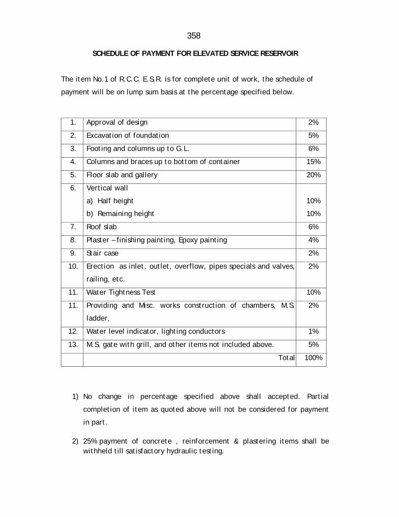
358
SCHEDULE OF PAYMENT FOR ELEVATED SERVICE RESERVOIR The item No.1 of R.C.C. E.S.R. is for complete unit of work, the schedule of
payment will be on lump sum basis at the percentage specified below.
1. Approval of design 2%
2. Excavation of foundation 5%
3. Footing and columns up to G.L. 6%
4. Columns and braces up to bottom of container 15%
5. Floor slab and gallery 20%
6. Vertical wall
a) Half height
b) Remaining height
10%
10%
7. Roof slab 6%
8. Plaster – finishing painting, Epoxy painting 4%
9. Stair case 2%
10. Erection as inlet, outlet, overflow, pipes specials and valves,
railing, etc.
2%
11. Water Tightness Test 10%
11. Providing and Misc. works construction of chambers, M.S.
ladder,
2%
12. Water level indicator, lighting conductors 1%
13. M.S. gate with grill, and other items not included above. 5%
Total 100%
1) No change in percentage specified above shall accepted. Partial
completion of item as quoted above will not be considered for payment
in part.
2) 25% payment of concrete , reinforcement & plastering items shall be withheld till satisfactory hydraulic testing.
359
Item No.2 – Providing and supplying ISI standard C.I.D.F. pipes etc. complete
The item is for providing and supplying CID/F pipes for 200 mm dia, 250
mm dia, 350mm dia and 600 mm dia CID/F pipes for ESR inlet, outlet and
overflow pipes.
The item shall be executed as per description of item in Schedule-B and
relevant IS specifications
Mode of measurement and payment
The item shall be measured and paid on Rmt basis. 85% payment shall be
released after supply of pipes with manufacturers test report, 15% after
jointing and satisfactory hydraulic testing of pipe.
Item No.3 – Providing and supplying ISI mark C.I. flanged S&S specials
Providing and supplying ISI mark C.I. flanged S&S specials, including all
taxes (Central and local), railway freight, inspection charges, unloading
from railway wagon, loading into truck, transportation upto
departmental store/site of wok, unloading, stacking etc. complete.
Mode of measurement & payment
The item will be measured and paid on Kilogram Basis. 85% of the
payment should be released after supply of specials at site and 15%
payment will be released after satisfactory hydraulic testing, is
completed.
Item No.4 – Providing and supplying C.I.D.F. sluice valve etc. complete.
The contractor shall procure C.I.D.F Sluice valves with wheel as per
IS:2906-1969 and revised latest edition. Valves of PN-1 rating shall be
provided. Only Kirloskar, I.V.C., IVI, Durga, Mayur, make valves shall be
accepted.

360
Mode of measurement and payment
The item shall be measured and paid on per number basis. 85% payment
shall be released after supply of pipes with manufacturers test report,
15% after jointing and satisfactory hydraulic testing of pipe.
361
MAHARASHTRA JEEVAN PRADHIKARAN
MAHARASHTRA JEEVAN PRADHIKARAN W.M. CIRCLE, PANVEL
MAHARASHTRA JEEVAN PRADHIKARAN W.M. DIVISION , AMBERNATH
NAME OF WORK: Augmentation to Ambernath Water Supply Scheme, Tal. Ambernath, Dist. Thane Construction of C.C. weir at Chikhloli Dam, Designing,
constructing & commissioning 7.20 ML capacity WTP at Chikhloli, lowering, laying and jointing D.I.K-7/K-9 pipes for rising main/gravity main/distribution system, construction of R.C.C. sump and pump house, construction of 8 nos. of RCC ESRs at various places with compound wall, construction of Consumer Redressal Centre with computerization, Railway crossing work, Repairs to Belivali MBR etc. complete.
ITEMWISE DETAILED SPECIFICATIONS Sub Work No-7: Lowering, laying and jointing D .I .Pipe distribution
system in Ambernath town. Item No -1- Providing and supplying D. I. Flanged, S&S Specials etc complete. 1.00 Providing D.I. S/S and flanged specials suitable for D.I. pipe, confirming
to IS:9523-2000 and as amended from time to time, including cost of
materials, taxes (Central and Local), insurance, railway freight,
unloading from railway wagon, loading into trucks transportation and
unloading at stores or site of work stacking etc. complete
2.00 Mode of Measurement and Payment
The item will be measured and paid on Kilogram Basis. 85% of the
payment should be released after supply of specials at site and 15%
payment will be released after satisfactory hydraulic testing, is
completed.
362
Item No -2:- Providing and supplying M.S. Specials etc complete. 1.00 Scope
Providing, fabricating M.S. Plates for specials for works, testing etc. at the
Contractor’s factory and testing the pipes
Transporting of fabricated specials from contractor’s factory to laying site or
MJP’s store as directed
These specials (detailed hereafter) specifications supplement, Standard
Specifications for Civil Construction Works prepared by the MJP for
(Maharashtra Jeeven Pradhikaran)
1.1 DRAWINGS The drawings accompanying the tender are indicative type drawings. Working
drawings shall have to be prepared by the Contractor.
1.2 SUPPLY OF MATERIALS TO THE CONTRACTOR
The MJP will not supply M.S. Materials such as plates; flats etc. required for
the fabrication of pipes, specials appurtenances etc.
The conveyance of fabricated materials from workshop to site of work shall
be deemed to have been covered in the relevant items of fabrication of
pipes, specials etc. The contractor should note that the steel plates and other
structural steel required for fabrication of specials is to be procured by him
from open market at his cost. The contractor has to procure such plates in
several stages as the circumstances demand, or, as directed by Engineer-in-
Charge.
The MJP shall not however supply any steel or structural steel to the
contractor for his use for preparing jigs, testing arrangements, platforms
etc. in the factory or in the field. The contractor shall have to make his own
arrangements for procuring them at his own
363
cost immediately or receipt of work order and the MJP shall not entertain
any request for extension of completion period of compensation on increase
in cost etc.
1.3 GENERAL
The main specials and appurtenances to be fabricated under this contract
are as per list following which is inclusive. The typical drawings for these
are accompanying / or may be provided during execution.
a) One piece cut composite bends. b) Loose flange rings c) Stiffener rings. d) Pressure and non-pressure type blank flanges e) ‘Y’ branches and tees, f) Tapers, bends
1.4 WORKMANSHIP
Loose Flange Rings
Loose flange rings shall be cut of the plates of suitable thickness as
directed by the Engineer. In order to avoid the wastage of steel plates,
shall be cut in maximum 4 segments, to form a complete ring when
welded together. Bolt holes of required size at the exact c/c distance in
required pitch circle shall be drilled through the flange rings. They shall
be mounted and tack welded on pipes/ specials etc. as shown on the
drawing whenever required.
Stiffener Rings
Stiffener rings shall be cut out of the M.S. channel of suitable size as
required by the Engineer-in-Charge. In order to avoid wastage, these
shall be cut in segments to form rings when welded together. These shall
be provided on site in segments sand shall be welded on the pipes as per
instructions of the Engineer-in-Charge.
364
Tapers
The tapers and bend shall be fabricated in one or more pieces as may be
necessary according to their lengths and sizes of plates available. These
shall have stiffening rings fixed on them as per details supplied by the
Engineer-in-Charge during fabrication
Special Care to be taken during Fabrication of Composite Bends, Tees
and ‘Y’ Branches
The testing of these specials is not envisaged at the fabrication stage.
These shall be subjected to test when the completed pipeline is tested
hydraulically. In view of this, the contractor in his won interest shall
fabricate these specials with all the care so that there is no failure of any
welded joint during testing of the completed pipeline, which will invite
dewatering the main, repairing and retesting. If directed by Engineer-in-
Charge, the contractor will have to manufacture M.S. bends from the
available M.S. Pipes by cutting and welding the pipe pieces as required
including painting of specials fabricated with red oxide paint and a
covering coat of gray graphite paint. In such cases payment will be
proposed for cutting and welding operations under relevant item work
and payment will be made under this item.
2.00 Mode of Measurement and payment
Fabrications of the various specials and appurtenances shall be measured
and paid under the relevant item in Schedule B on weight basis. These
items shall include the cost of supply of all labour, material (unless
otherwise stated) and machinery for fabricating theses and
appurtenances as per specifications and shall include all cost of materials
and handling materials within the fabrication yard stacking them properly
in the yard, transporting from factory to site, including loading,
unloading and all other ancillary works involved. Deductions for bolt
holes shall not be made while
365
computing weight for payment. 85% payment will be made immediately
after supply of M.S. specials. 15% after lowering ,laying, jointing and
satisfactory hydraulic testing is given.
Item No 3:- Providing and supplying ISI mark Sluice valves etc complete 1.00 GENERAL
The Sluice Valves proposed to be procured through this tender are to be
used for drinking water supply schemes under execution.
1.1 WORK UNDER THIS CONTRACT
The work entitled manufacture, supply and delivery of Sluice valves for
transmission mains shall comprise the manufacture, supply and delivery
of the goods as mentioned in Schedule B.
C .I. D.F. Sluice valves of MJP approved make shall be accepted. The
Sluice valve shall confirm to IS 780 and IS 2906-1984 or as per
subsequently modified IS of relevant year.
The above goods to be used for conveyance of potable water at
temperatures varying from 10 degree centigrade to 40 degree centigrade.
The tender rate shall include all labour and machinery and all materials
necessary for the proper, manufacture of the goods, for tests at the
contractor’s works for the insurance and for delivery to works for the
proper maintenance and for discharging every obligations and
requirement of the contract, in accordance with the intent of the
contract documents, as stated in the General Conditions of Contract.
1.2 STANDARDS
Where reference is made to a particular standard, it shall be the latest
revision of the Indian Standard Institution. Unless otherwise
366
specified, the sluice valves shall be in accordance with the provisions of
IS:780:1980 and IS:2906:1984 or sizes of the sluice valves covered under
relevant standards.
1.3 MARKING OF SLUICE VALVES
Each sluice valve shall be marked as per IS:780:1980, Para-II for sizes (50
mm to 300 mm) and IS:2906:1984, page: 11.1 (for sizes 350 mm to 1200
mm).
1.4 PACKING AND HANDLING
The contractor shall dispatch from the manufacturer’s works goods
adequately protected to prevent damage and deterioration during
transportation and storage, etc. The packing is to be quite robust to
withstanding rough handling during the transit by road/ rail/ sea and
storage.
Each package / create will contain sluice valve of one size only in
relevant class.
The packing procedure followed shall be in accordance with para 12 of
IS:780:1980 and para 12.1 of IS:2906:1984
The contractor shall use proper handling equipment or follow suitable
handling method as approved by the Engineer to unload the materials at
the delivery site to prevent damage to the goods and equipments.
Third party inspection from agency approved by MJP. should be carried
out at contractor’s cost only.
The contractor should produce manufacturer’s test certificate
conforming that the valves have been tested in accordance with I.S.
specifications, stating the actual pressure and the medium used in the
test. The design workmanship, material, strength and
367
dimensions of all parts shall be as per I.S.S. The product shall be of
proven quality rendering reliable service during maintenance and
requirement.
2.00 Mode of measurement and payment
The item shall be measured and paid on per No. basis. 85% payment shall
be released after supply of valves with satisfactory 3rd party inspection
report, 15% after lowering, laying, jointing and after satisfactory
hydraulic testing of sluice valve.
Item No 4:- Supplying C I Mechanical Compression Collar Coupling (Jiffy
Joints)
1.00 The item shall be executed as per description of item in schedule-B and
as directed by Engineer -in-Charge.
2.00 Mode of Measurement and Payment
This item will be measured and paid per number basis. 85% Payment
shall be released after supply and fixing of joints at site and 15% after
satisfactory hydraulic testing is completed.
Item No 5:- Providing and Supplying C. I .D .Joints etc complete 1.00 The item pertains to providing, supplying and fixing C.I. Detachable joints
at cross connections or any other places as per requirement. The cost of
providing necessary materials, with transportation of materials upto site
of work, providing necessary labour and equipment in fixing CID joints is
included.
The work shall be executed as per description of item in Schedule-B,
relevant I.S. and as directed by Engineer-in-Charge.
2.00 Mode of Measurement and Payment
This item will be measured and paid per number basis.
368
Item No.6 – Excavation for pipe trenches in average all types of strata of earth, soil of all types, sand, gravel, soft murum, hard murum with boulders, soft rock, hard rock by mechanical chiseling & all means … etc. complete.
1.0 GENERAL The specifications contained in the standard specification volume IInd
published by Public Works and Housing Department, Govt. of
Maharashtra, Chapter Bd.A-9 shall apply. In addition to above following
specification shall apply. In case of any discrepancy between the two the
below given specifications shall govern.
1.1 SITE CLEARANCE The area to be excavated shall be cleared off all trees and bushes and
rubbish and other objectionable materials removed shall be burnt or
disposed off as directed by the Engineer-in-Charge. The cost of such
clearing shall be deemed to have been included in the rates accepted for
different items under excavation.
1.2 DEWATERING No distinction shall be made as to whether the materials being excavated
are dry, moisture or wet. The item also includes bailing out of water by
manually to keep the trenches reasonable dry for all further works of
lowering, laying, jointing and testing of the pipe line till the completion
of the work.
1.3 SHORING AND STRUTTING The item includes all shoring and strutting that may be required. On no
account the width of trenches more than these mentioned here in after
shall be measured. If excavation width more than the specified is
required for the purpose of keeping machinery, steeping due to loose
material or for any other reasons the same shall be at the Contractors
cost.

369
1.4 LIGHTING, BARRICADING AND GUARDING The items of excavation are including necessary lighting at night at
suitable intervals, but not more than 15 meter along the excavated
trenches and at all crossing and barricading the same by fencing so as to
avoid the accident. Chowkidars shall be employed at place where the
trenches cross over any traffic road to caution the vehicles and
pedestrians etc.. The arrangements shall be maintained till completion
of work and at the cost of the Contractor.
1.5 ALIGNMENT AND LEVELS
Before the trenches excavation is commenced, sight rails shall be
erected at every 30 meters and at all points of change of direction,
gradient and at ends. The excavation work shall be proceeded by a
detailed survey along the alignment of the main to obtain ground levels
at every 30 meters or less distance. Temporary bench mark shall be
constructed at every 30 meters distance along the alignment and shall
be maintained till the completion of work. All labour and materials
required for the survey work of fixing bench mark etc. shall be provided
by the contractor at his own cost. For any mistakes in survey the
contractor is fully responsible. He should not lay the pipes, unless the
alignment is thoroughly checked by the Engineer-in-Charge or his
authorized representatives who is empowered to sign the work order
book in token of checking the exact grade and level of the trench
excavation.
Excavation at random places shall be measured available to the MJP
Engineer for checking. Any non technical practices during the
excavation of the contracted work shall be viewed very seriously by
the MJP and a note to that effect will be recorded against the
contractor in his name.
370
1.6 DEPTH AND GRADES OF TRENCHES
The trenches shall be excavated to the required grades and depths and
on the lines as shown on approved drawings as directed by the
Engineer-in-Charge. The depth of excavation and the levels of the pipe
inverts shall be checked by means of boning rods of suitable lengths.
Additional depths if required to be excavated for pipes, for sockets,
collars, specials, joints and for any other working facility and shall
not be measured and paid.
The contractor shall notify the Engineer when the trenches are ready for
bedding so that the Engineer can inspect and record the depths. Only on
explicit approval by Engineer, the bedding shall be provided by the
contractor.
1.7 WIDTH OF TRENCHES
The maximum width of the trenches admissible for payment shall be as
below or actual excavated width whichever is less shall be recorded and
paid for. Extra widths for pits at sockets, collars, specials, joints,
construction and also for working liabilities shall neither be measured
nor paid for. However, excavation required for providing and casting
fixity block, thrust blocks, encasing etc. will be measured and paid for
under relevant item of excavation. Trench excavation and back filling
should be strictly in accordance with detailed specification. Extra
dimensions if required at site of work due to any unavoidable reason will
not be paid to the Contractor.
A) For D.I. Pipes/C.I. Pipes i) 100 mm dia 0.75 M ii) 150 mm dia 0.75 M iii) 200 mm dia 0.80 M iv) 250 mm dia 0.85 M v) 300 mm dia 0.90 M
371
vi) 350 mm dia 0.95 M vii) 400 mm dia 1.00 M viii) 450 mm dia 1.05 M ix) 500 mm dia 1.10 M x) 600 mm dia 1.20 M 1.8 CLASSIFICATION OF MATERIALS IN EXCAVATION The exact classification of the strata likely to be met with during the
excavation for which average rate is worked out for all strata described
in Item of this sub work. The contractor shall carry out his own
assessment regarding the strata at different depths along the alignment
before submission of the tender.
1.9 EXCAVATION BY CHISELING, WEDGING IN HARD STRATA The contractor shall note that blasting may not be permissible at some
places, due to likely hood damages to any public or private property.
Excavation will have to be by chiseling, wedging in hard rock is required
to be carried out close to habitation or similar other risk involved
locations, payments for excavation will be made at the rates of
concerned item of Schedule ‘B’ as cost of excavation by chiseling,
wedging is inclusive in item itself. Any damage to private or Government
of Maharashtra Jeevan Pradhikaran’s property, be reinstated by
contractor at his own cost.
The item of chiseling wherever appears shall mean chiseling by all means
other than blasting including mechanical / pneumatic / rock splitters or
any methodology.
2.00 MODE OF MEASUREMENT AND PAYMENT
The excavation shall be measured in Cubic Meters only. Dimensions shall
be measured correct to two decimal of Meter and quantity shall be
calculated to two places of Decimal of Cubic Meters, if any additional re-
excavation is required for hydraulic testing of pipe, the same will not be
admissible for payment. 10% amount will be withheld till satisfactory
hydraulic testing is given.

372
Item No.7 – Filling in plinth and floors murum bedding in trenches etc. complete.
1.00 The murum to be used for bedding shall be of approved quality soft
murum to be laid in 15 Cms. thicknesses to the grade as directed by the
Engineer-in-charge. The width admissible for payment shall be the same
as per excavation item. The murum bedding shall be provided where
there is black cotton soil or hard material below pipes or wherever
directed and it shall be well rammed so as not to sink the pipe line. Extra
excavation for murum bedding, wherever required as above shall be
admissible for payment under excavation.
2.00 MODE OF MEASUREMENT AND PAYMENT
Murum bedding shall be measured in Cubic Meters only. Dimensions shall
be measured correct to two decimal of Meter and quantity shall be
calculated to two places of Decimal of Cubic Meters. 10% amount will be
with held till satisfactory hydraulic testing is given.
Note:-
1) The rate includes excavation in all types of strata viz. hard and soft,
the excavation shall be carried out by all means.
2) Excavation in all types of strata for pipe line work shall be done for
required full depth of trench, otherwise payment shall not be made
for complete depth of trench.
Item No.8 – Refilling the trenches etc. complete. 1.00 After lowering, laying and jointing of pipe line, concreting work and
testing of pipe line refilling of trenches with available excavated stuff
shall be done.
The available excavated stuff shall be laid in layers of 15 to20 cm. Each
layer shall be watered and compacted before the upper layer is laid till
the required level is reached.
373
First 2 layers of 15 cm to 20 cm shall be free from stones or chips or any
harmful material, to protect the pipe from damage.
Only soil or soft murum shall be used for filling.
Originally filling shall be done 30 to 40 cm above natural ground or road
level. Sinking below the road or ground level, if noticed till the
completion of work the contractor shall have to make it level at his cost.
This item includes, a) Cleaning useful excavated materials of rubbish braking clods, stone etc. b) Conveying the useful excavated material for all leads and filling in layers,
watering and compacting. c) All labour, equipment and other arrangements necessary for the
satisfactory completion of item. 2.00 Mode of Measurements
The item shall be measured and paid on Cum. Of compacted trenches
filling with approved excavated material. The measurement shall be net
for the compacted filling and no deduction for shrinkage or voids shall be
made. However, deduction of pipe volume shall be made. Depth of
filling for measurement will be limited from natural ground level only.
Surplus excavated material is the property of Maharashtra Jeevan
Pradhikaran, so Contractor is not empowered to sell this excavated
material to any other agency. This disposal will not be considered for
initial50 m lead from edge of pipe line trenches and so will not be paid
for. The material shall be conveyed by means of suitable
devices/manner.
The material conveyed to the place of disposal shall either be stocked or
spread as directed by Engineer-in-Charge or his representative.

374
The route opening and maintenance, payment of any royalties,
compensation land owners and for damages if any etc. during the process
of conveyance etc. shall be entire responsibility of the contractor.
Though the contractor is required to be refilling before hydraulic testing
to avoid traffic handle, no payment of refilling of trenches of pipe line
shall be payable still satisfactory hydraulic testing is given, re-
excavation, if any during testing shall be done by the contractor at his
own cost.
Item No.9 - Providing and laying Plain cement concrete ---etc complete
1.00 CONCRETE PROPORTION a) Proportions of concrete for types of work
M-150- PCC for encasing, anchor block, thrust block etc. complete
b) General specifications of this work shall be as per standard
specification of Public Works Department, latest edition,
Section BdE-1, Page no 287.
c) Whenever concrete is to be laid in trenches, the trench shall be
cleaned, and watered before placing. The sub- soil water which is
met shall be removed and the trench shall be kept dry during and
after 2 hours of placing concrete.
2.00 MODE OF MEASUREMENT AND PAYMENT The tender rate shall be for one cubic meter of concrete. The
concrete shall be measured for its length, breadth and depth
limiting dimensions to those specified in drawing or as per
direction of Engineer- in-Charge. 10% amount will be with held till
satisfactory hydraulic testing of pipe line is given.

375
ITEM NO.10 – Lowering, laying & jointing DI S/S pipe etc. complete.
1.00 The tender item covers Lowering, Laying & Jointing D.I. Pipes as well as
D.I. / C.I. / M.S. Specials, pipe pieces, etc. as per requirements and as
directed by the Engineer-in-Charge, by rubber gasket joints, viz. Tyton
Joints.
The cost of conveyance of these materials to place of the site of work is
also included in the tender item.
The item includes jointing D.I. pipes with rubber gasket joints, including
laying and jointing D.I. / C.I. / M.S. Specials. The method of jointing
with tyton joints (i.e. rubber gaskets) is as under.
The rubber gaskets is inserted in the socket of the pipe which is
facilitated by applying thin file of lubricating oil in such a way that the
bulb of gasket is forwarded at the back and the socket and the groove in
the gasket should firmly fixed in the projecting ring inside the socket.
The gasket has to be properly cleaned before inserting and it has to be
ensure that it fits evenly around the whole circumference of the socket,
removing any bulges which would prevent the entry of spigot end, then a
thin film of lubricant should be applied to the gasket, inside surface and
outside surface of entering spigot end for one inch distance after cleaning
it. The pipe to be jointed should be supported correctly by the tackle, so
that it is clear of trench bottom.
The spigot of the pipe shall be carefully aligned and inserted in the
adjoining socket, until it make contact with the rubber gasket. The spigot
shall be forced inside the socket, past the gasket (which is thus
compressed) until the spigot reaches the end of the socket. The forceful
insertion has to be achieved with crowbars, jacks and lowers, etc. as per
the details given in the Literature of TISCO or any other suitable method
as directed.
376
However, before lowering of pipes in trenches a layer of murum bedding
from the excavated stuff will have to be provided below the pipe line for
proper grading and alignment and also to act as cushion and support to
pipe. The murum bedding will be paid under item of refilling as it forms a
part of refilling item.
1.1 HYDRAULIC TEST
Suitable section as directed by the Engineer-in-Charge shall be taken for
such testing from time to time during progress of the work and
satisfactory test given for that section. All testing apparatus, gauges,
connections etc. and water required for testing shall be arranged by the
contractor at his cost. MJP does not undertake any responsibility to
supply water for testing, which contractor has to arrange from the
municipality or otherwise by paying the required charges directly. The
MJP shall have the right to recover such charges from his bills if
complaints are received that contractor has not paid the charges thereof.
If there is delay in testing the contractor shall refill the trenches for the
time being and re open them at time of testing at his own cost, failure of
which shall entitle the MJP to do the refilling and reopening of trenches
at the risk and cost of the contractor if the trenches are refilled due to
any reason whatsoever before testing the contractor shall have to open
them for testing at no extra cost.
i. Satisfactory hydraulic test shall be regarded when the section under test
shall withstand the pressure as specified by the Engineer-in-Charge for
about 15 minutes without operating the test pump, the test pressure
being maintained at the specified figures during that 15 minutes interval.
ii. The entire pipe line, specials and all joints in that section appears to be
dry. The test pressure shall be as per designed the test pressure of
particular class of pipe.
377
During testing if any joints are found leaky they shall be repaired and/or
redone by the contractor at his cost till the test is found satisfactory.
Similarly any pipes, collars, specials show hair cracks, leaks etc. during
testing, the contractor shall replace them with sound pipe and specials
together with new joints, entirely at his own cost till a satisfactory test is
given. The pipe, specials etc. which cracks during testing will, however,
be supplied by the contractor, replacement free of cost. The hydraulic
test shall be given in the presence of the Engineer-in-Charge.
10% payment of respective items shall be withheld till hydraulic test is
given which shall be released only on giving satisfactory test.
After laying and jointing any pipe line, the pipe line must be pressure
tested to ensure that pipes and joints are strong enough to withstand the
maximum pressure, likely to be developed under working condition. In
this G.O.I. Manual on water supply and Treatment (3rd Edition, March
1991) describes the field test pressure to be imposed on pipe lines. In this
respect, for DI pipes, concerned para 6.5.2 from this manual is
applicable.
Thus, for DI pipes, field test pressure is as per Para 6.4.2.2. As per
paragraph, the field pressure is to be imposed should not be less than the
maximum of the following.
a) 1.5 times the maximum sustained operating pressure.
b) 1.5 times the maximum static operating pressure in the pipeline
c) Sum of maximum sustained operating pressure and the maximum surge
pressure.
d) Sum of maximum pipe line static pressure and the maximum surge
pressure, subject to a maximum equal to the work test pressure for any
pipe fittings incorporated.
378
Here, it is to be noted specifically that, while determining the class of
pipe, along with other conditions, aspect of above field hydraulic test
pressure should also be considered.
Above working pressure, it is clarified that working / operating pressure
is the maximum sustained internal pressure, excluding the one coming in
abnormal condition such as average (water hammer) to which the pipe
line may be subjected to when in use. All the field tests should be carried
out for the pressure as clarified above only.
2.00 MODE OF MEASUREMENT AND PAYMENT The item shall be measured and paid on the Running Meter basis.
Dimension shall be measured correct to two decimal meter. The
15% payment shall be with held for till satisfactory hydraulic
testing is given.
Item No.11 – Lowering, laying & jointing Sluice Valve etc. complete.
1.00 GENERAL
The specification lays down the requirement for lowering, laying and
jointing Sluice valves.
1.1 PREPARATION
The sluice valves and tail pieces shall be examined before laying for
cracks and other flows. Only undamaged S.V. shall be used.
The sluice valve shall be operated and checked before laying.
All the four faces shall be thoroughly cleaned and coated with a thin
layer of mineral grease.
The tightening of gland shall be checked with a pair of inside callipers.
Clearance between the top of stuffing box and the underside of the gland
shall be uniform on all sides.

379
1.2 JOINTING MATERIALS
The contractor shall provide all the necessary jointing materials such as
nuts, bolts, rubber packing, white zinc, jute lead wool etc. at his cost.
All tools and plant required for installation of sluice valve shall be
provided by the contractor at his cost.
All the jointing materials shall be got approved from the Engineer-in-
charge before use.
The nuts and bolts shall be conform I.S.1364 and the rubber packing shall
conform I.S. 638.
1.3 INSTALLATION
The sluice valve shall be lowered into trenches carefully so that no part is
damaged during lowering operation. If necessary tail pieces shall be
fitted with sluice valve first outside the trench and then lowered into the
trench.
The rubber packing shall be three ply and of approved thickness. The
packing shall be of full diameter of the flange with necessary holes and
the sluice valve bore. It shall be even at both the inner and outer edge.
The flange faces shall be thoroughly greased. If flanges are not free the
contractor shall use thin fibers of lead.
After placing the packing, nuts and bolts shall be inserted and tightened
to make the joint. The valve shall be tightly closed being installed to
prevent any foreign materials from getting in between the working parts
of the valve.
Each flange bolt shall be tightened a little at a time taking care to
tighten diametrically opposite bolts alternately.
380
The sluice valve shall be installed in such a way that spindle shall remain
in truly vertical position.
The other end of the tail piece shall be fitted with pipes so that
continuous lines can work. Extra excavation necessary for facility of
lowering and fixing of sluice valve shall not be paid for.
2.00 Mode of measurement and payment
The item shall be measured and paid on per No. basis.
Item No.12 – Providing constructing BB masonry Valve Chamber etc.
complete.
1.00 The size of the chamber shall be as mentioned in the description of item
and it shall be the internal size. This is completed item.
The tender item covers PCC at bottom on well rammed surface and B.B.
masonry walls with inside cement plaster and CC coping on the top of
B.B. masonry. The work of CC and B.B. masonry shall be carried out as
per detailed specification of respective items. The covers shall be of
precast slab as specified in description of item.
The work shall be carried out as per detailed drawing of the chamber
supplied by the Engineer in charge. The chamber shall be flush with road
surface and shall not cause any hindrance to the traffic.
The precast covers shall be of the dimensions as specified in the
drawings.
This shall include the cost of reinforcement, concrete. Precasting,
curing, conveyance
and fixing the RCC precast cover.
2.00 Mode of measurement and payment
The item shall be measured and paid on per No. basis.
381
Item No.13 –Providing 50mm thick full grout bituminous road surface etc.
complete.
1.00 General
The work consists of supply of all materials and labour required for
providing and laying bituminous macadam surface for completed
thickness of 50mm. This item includes preparation of existing road
surface (portion of excavated trenches for pipe line) to receive the
bituminous behind macadam course, spreading of 40mm size metal
layer in required thickness with compaction with power roller,
spreading 20mm chips, compaction with power roller, heating and
spraying bitumen with equipment plant etc. spreading key aggregate
12mm chips and final compaction and in close conformity with grades,
lines, cross section and thickness as per approved drawings and
standard specification of PWD of Section RD-59, Page 232 or as
directed by the Engineer-in-Charge.
1.1 Material
The bitumen shall be paving of suitable grade (bulk asphalt 60/70
grade) as per Indian Standard Specification for “Paving Bitumen : IS “
1873 : 1961. The actual grade of bitumen to be used shall be decided
by the Engineer-in-Charge appropriate to the region, traffic, rainfall
and other environmental conditions.
1.2 Aggregate
The aggregate shall comprise of 40mm size hand broken stones
satisfying standard specification clause Rd.22.3.2, Page 201 of edition
1979, 20mm size and 12mm size crushed aggregates satisfying
standard specification clause Rd.31.3.2, Page 216 of edition 1979 for
respective size of crushed metal. The aggregate shall be clean,
strong, durable and fairly cubical in shape and shall be free from
disintegrated pieces, organic or other deleterious matters. The
aggregate shall satisfy the physical requirements set
382
forth in Table 500-4 of Ministry of Surface Transport’s Specification
for road and bridges edition June 1992.
1.3 Proportioning of Materials
The quantities of aggregates and bitumen required for the work of 50mm
compacted bituminous bound macadam is detailed below :
a) 40mm size hand broken metal 9.00 cum per 100 Sqmt.
b) 20mm size crushed etc 1.50 cum per 100 Sqmt.
c) 12mm size crushed metal 1.80 cum per 100 Sqmt.
d) Bitumen including tack coat at 250 Kg/100 Sqmt 50 Kg/100 Sqmt
1.4 Preparation of Base
The road surface shall be swept clean of all dirt, dust and other loose and
foreign matter. The work shall be performed widths and lengths as
directed by Engineer-in-Charge and may require spreading rubble soling
on the refilled surface ramming etc. The edge lines may be marked with
stakes (formed of murum or metal 25cm to 30 cm width)
1.5 Spreading and Compaction
Spreading of 40mm size metal
40mm size hand broken metal shall be spread evenly at the rate of 9
cum/100 Sqmt of area so as to form uniform layer over the width of road
specified on plants. Any foreign matter, organic matter, dust, grass etc.
shall be removed immediately. The section shall be checked with camber
board, straight edge batten etc.. Any irregularities shall be made good by
adding aggregates in case of depressions and removing aggregates from
hight spots.
1.5 Compaction of 40mm size metal
The surface of 40mm size metal layer after brought to necessary grades
and sections shall be rolled with the use of 8 to 10 tons
383
power roller. Rolling shall be commence from the edges and progress
towards the center longitudinally except on super elevated portion is
shall progress from the lower to upper edge parallel to the centerline of
pavement. When the roller has passed over the whole area as prepared
once, any high spots or depressions, which become apparent, shall be
corrected by removing or adding aggregates. The rolling shall then be
continued till the entire surface has been rolled to desired compaction
such that there is no crushing of aggregates and all other roller marks
have been eliminated. The each pass of roller shall uniformly overlap not
less than 1/3 of the track made in the preceding pass.
1.6 Spreading of 20mm size metal
20mm size crushed metal shall be evenly spread at the rate of 1.5 Cum /
100 Sqmt of area over the 40mm size hard hand broken metal
compacted.
1.7 Compaction after spreading of 20mm size metal
The surface of 20mm metal layer after brought to necessary grades and
sections he rolled with the use of 8 to 10 ton power roller. Rolling shall
commence from edges and progress towards the center longitudinal
except on super elevated portion it shall progress from the lower to
upper edge parallel to the center line of pavement. When the roller has
passed over the whole area as prepared once, any high spot or
depressions, which become apparent, shall be corrected by removing or
adding aggregates. The rolling shall then be continued till the entire
surface has been rolled to desired compaction such that there is no
crushing of aggregates and all other roller marks have been eliminated.
The each pass of roller shall uniformly overlap not less than 1/3 of the
track made in the preceding pass.
384
1.8 Bitumen application
Bitumen to be used shall be got approved from Engineer-in-Charge of IS
grade 535 needs heating to a temperature range between 177 degree to
191 degrees. Bitumen other than grade IS 535 shall be heated toa
temperature appropriate to that grade. Bitumen shall be applied through
a pressure sprayer uniformity at the rate of 125 kg/100 Sqmt. To ensure
correct application of bitumen being spread, known dimensioned area be
checked for use bitumen and accordingly dosage may be increased or
decreased as the case may be.
1.9 Key Aggregates
On completion of bitumen application, 12mm size key aggregates shall be
spread immediately at a uniform rate of 1.8 Cum. Per 100 Sqmt of area
when entire surface is in hot condition. Brooms shall be used ensure even
distribution of key aggregates.
1.10 Final Compaction
Immediately after spraying of bitumen and spreading of key aggregates,
the surface shall be rolled with a powered roller to obtain full
compaction and to force the bindage of key aggregates in to the
interstices of the course aggregates. The rolling shall continue till the
asphalt surface hardness and key, aggregates slop moving under power
roller.
1.11 Surface Finish and Quality Control
The surface finish shall conform to requirement of clause 902 of
specification for Roads and Bridges by Ministry of Surface Transport.
Quality control test and their requencies shall be as per para 5 of table
900-3 on Page 228 specification for Road and Bridges by Ministry of
Surface Transport.
1.12 Arrangement of Traffic
During the period of execution, arrangement of traffic shall be carried
out according to the Clause 112 (excluding last para of
385
112.6) of specification for Roads and Bridges by Ministry of Surface
Transport.
This item shall be executed as per wording of item in Schedule-B, after
completion of pipe line testing and satisfactory refilling.
1.13 Item to Include
a) Labour and materials required for preparing surface.
b) Supplying, spreading, compaction of required metal layers.
c) Supplying, spreading, compaction of 40mm hand broken size metal
and 20mm crushed metal.
d) Supplying, heating and spraying of bitumen (bulk asphalt 60/70
grade)
e) Supplying, spreading and compaction of 12mm crushed metal.
f) Seal coat at 125 Kg/100 Sqmt.
2.00 Mode of Measurement
The completed item rate for finished work of full grout bituminous bound
macadam is in full for carrying out all operation as detailed in Para
named item to include. The finished work shall be measured & paid in
Sqmt. Basis.
Item No.14 – Providing & fixing C.I. Road Box etc. complete.
1.00 The item includes providing, supplying and fixing C.I. road box of size 100
x 225 mm (20 Kg) at site of work including necessary taxes, loading,
unloading and transportation to site of work, including all necessary
excavation in all types of strata and fixing in murum packing etc.
complete
2.00 Mode of measurement and payments
The item shall be measured and paid on per number basis.
386
Item No.15 – Dewatering the excavated trenches etc. complete 1.00 The contractor shall furnish, install and operate all necessary machinery
appliances and equipments and shall furnish all labour necessary to keep
excavations free from water during construction and shall dispose of
water so as not to cause flooding of construction works, injury to private
property or to persons, or to cause a nuisance or menace. Before, during
or just after any construction works, including pipe laying, excavation
shall be kept free of water. Bunds shall be provided to prevent surface
water from draining into structural excavation. Earth banks shall be
suitably protected from damage by erosion during construction. Any
damage occurring shall be repaired by the contractor on his expenses, in
a manner approved by the Engineer. When dewatering is separately
provided for under a special item, it will deem to include all cost of fuel,
labour, required for the job and all expenses related to this job. All
machinery and equipments are supposed to be arranged by the contractor
at his own cost. The item of dewatering includes any work of coffer dam;
diversion or river / nalla flow etc. unless specific provision for such item
exists under a separate item.
2.00 MODE OF MEASUREMENT - JOB – Lump Sum
During execution dewatering through running bill will be paid as below.
1. After completion of 40% laying work = 25%
2. After completion of 60% laying work = 15%
3. After completion of 80% laying work = 20%
4. After completion 100% laying work = 30%
10% Amount will be withheld till satisfactory testing is given for whole
work.
Item No.16 – Disposing of surplus excavated materials etc. complete.
1.00 The tenderer shall dispose all the surplus excavated stuff within a
distance of 5 Km.. The disposal shall include collecting and filling the
material into truck, cart/tractor etc. conveying into a desired

387
disposal site, unloading, leveling the disposal material etc. complete.
The disposal shall be done at the sites as directed and shown by the
owner or his authorized representative of MJP and shall not be done at
any other place than shown by the owner or his authorized
representative. If disposal is done at any other places than shown by the
owner or his authorized representative then no payment will be
admissible to the contractor on this account and owner reserves the right
to recover the cost of material from the contractor at the prevailing
market rate of supply of murum.
2.00 Mode of measurement & payment
Payment shall be made on the Cubic meter basis of disposal surplus
quantity. In no case the quantity of surplus excavated stuff disposed
should exceed the total quantity of volume of murum bedding, rubble
soling, pipe volume, PCC, RCC etc. complete.
Item No.17 – Supplying S.P. fire hydrants etc. complete.
1.00 Supplying, transporting the S.P. fire hydrants including duct foot, bends,
S.V and S.V. road box, painting the hydrant, fixing the saddle pieces,
supplying and laying required length of C.I. pipe line and jointing the
same, spun yarn, molten lead including caulking fixing the S.V/ road box
in one brick masonry chamber in 1:5 CM with 12 mm thick 1:3 cement
plaster both inside and outside on 1:3:6 CC 150 mm thick etc. complete
as specified and directed. (As per IS:900:1965 latest version)
The item shall be executed as per description of item in Schedule-B and
as directed by Engineer-in-Charge.
2.00 Mode of measurement and payment
The measurement of this item shall be taken as per number basis of
completed work as per description of item.
388
Item No.18 – Providing & fixing M.S. chequered plate etc. complete.
1.00 Providing and fixing MS chequered plate flooring of following thickness
supported on MS angles (25 x 25 x 5 mm size) including welding, cutting
and fabricating the plate to the required square or round shape, making
holed in the plate, including providing and applying 3 coats of
anticorrosive paint etc. complete as directed by Engineer-in-Charge. – 8
mm thick
The item shall be executed as per description of item in Schedule-B and
as directed by Engineer-in-Charge.
2.00 Mode of measurement and payment
The measurement of this item shall be taken square meter basis. Actual
length and breadth shall be measured upto 2 decimal point.
Item No.19 Making cross connection to existing distribution main etc. complete.
1.00 This item incorporates the work of cross connection to existing
distribution mains and newly laid D.I. pipe line. Materials such as
required pipes, specials, valves will be paid separately under relevant
item. The connections joint should be water tight at maximum working
pressure. The work shall be executed as per description of item and as
per directions of Engineer-in-Charge.
2.00 Mode of Measurement
This item will be measured and paid on per number basis. 10% amount
will be withheld till satisfactory hydraulic testing is given.
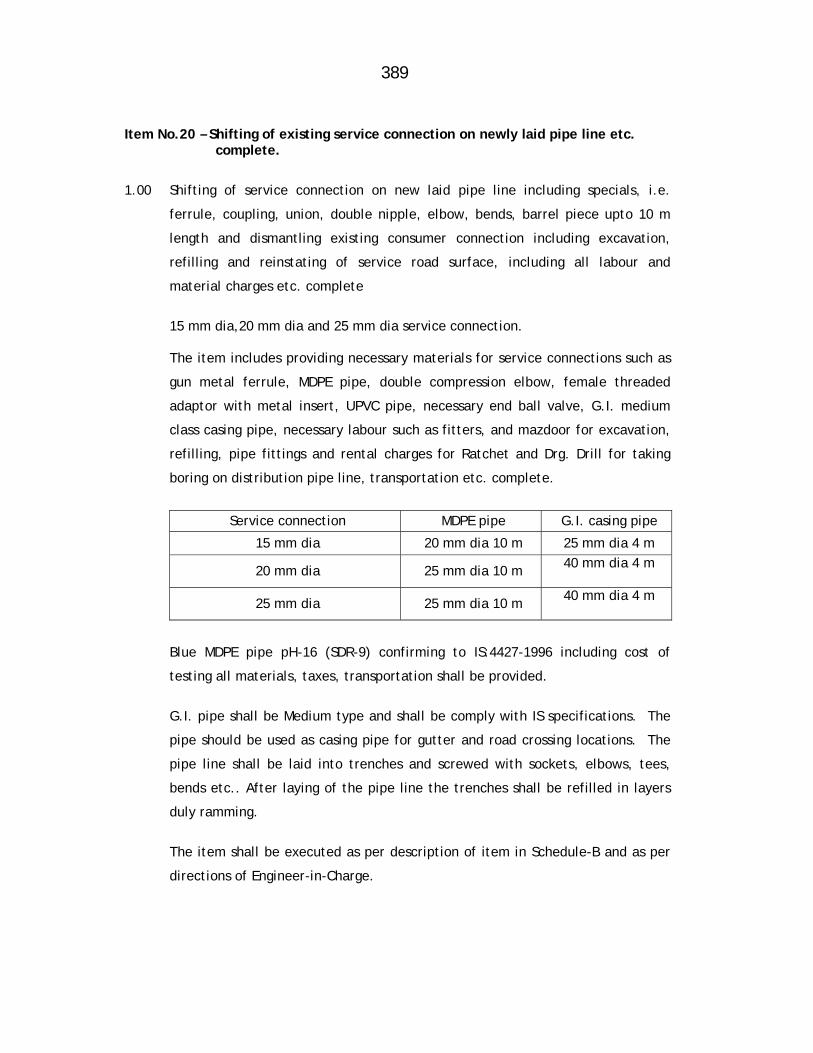
389
Item No.20 – Shifting of existing service connection on newly laid pipe line etc. complete.
1.00 Shifting of service connection on new laid pipe line including specials, i.e.
ferrule, coupling, union, double nipple, elbow, bends, barrel piece upto 10 m
length and dismantling existing consumer connection including excavation,
refilling and reinstating of service road surface, including all labour and
material charges etc. complete
15 mm dia,20 mm dia and 25 mm dia service connection. The item includes providing necessary materials for service connections such as
gun metal ferrule, MDPE pipe, double compression elbow, female threaded
adaptor with metal insert, UPVC pipe, necessary end ball valve, G.I. medium
class casing pipe, necessary labour such as fitters, and mazdoor for excavation,
refilling, pipe fittings and rental charges for Ratchet and Drg. Drill for taking
boring on distribution pipe line, transportation etc. complete.
Service connection MDPE pipe G.I. casing pipe
15 mm dia 20 mm dia 10 m 25 mm dia 4 m
20 mm dia 25 mm dia 10 m 40 mm dia 4 m
25 mm dia 25 mm dia 10 m 40 mm dia 4 m
Blue MDPE pipe pH-16 (SDR-9) confirming to IS:4427-1996 including cost of
testing all materials, taxes, transportation shall be provided.
G.I. pipe shall be Medium type and shall be comply with IS specifications. The
pipe should be used as casing pipe for gutter and road crossing locations. The
pipe line shall be laid into trenches and screwed with sockets, elbows, tees,
bends etc.. After laying of the pipe line the trenches shall be refilled in layers
duly ramming.
The item shall be executed as per description of item in Schedule-B and as per
directions of Engineer-in-Charge.

390
2.00 Mode of measurement and payment
The measurement of this item shall be taken as per number basis of completed
work as per description of item and specification. Payment will be made per
number of service connections shifted.
Note:- 10% amount of the item shall be with held till satisfactory hydraulic
testing
Item No.21 – Cutting & chamfering of pipes etc. complete.
1.00 Cutting and champhering of pipes as per diameter mentioned in item including cost of all materials and labour involved etc. complete, as directed by Engineer-in-Charge (for all class of pipes)
The item shall be executed as per description of item in Schedule-B and as directed by Engineer-in-Charge.
2.00 Mode of measurement and payment
The item shall be measured diameter wise per cut and payment shall be made on per cut basis
Item No.22:Providing & supplying rubber gaskets for DI pipes & Specials
etc.complete. 1.00 Providing and supplying ISI mark rubber gasket suitable for C.I./D.I. pipe of all
class for tyton joints including all taxes (Central and local) inspection charges,
transportation to departmental store/site of work etc. complete (SBR Gasket to
be used as per IS:5382 & IS:1280).
The item shall be executed as per description of item in Schedule-B and as
directed by Engineer-in-Charge. Rubber gaskets for laying pipe line shall be
provided free of cost by department. This item is for fixing DI/CI specials during
laying of pipeline.
2.00 Mode of measurement & payment
The item shall be measured and paid on per No. basis. Item No.23 Providing structural steel works in single stanchion etc. complete. 1.00 This item covers MS/RS girders, MS angle, channels, flats, base plates, gusset
plates, cleat, bracket etc. and other accessories as per requirement and as directed and fabricating the assembly by cutting, drilling holes, etc. and erecting and fixing item as site with necessary riveted or welded joints, fixtures with nuts and bolts, etc. for chamber covers in heavy traffic area wherever necessary together with their proper fixing and embedding in masonry or slabs of concrete as directed. Structural steel works materials shall be procured by the contractor from open market at his cost. The item includes 1 coat of anticorrosive paint and 2 coats of oil paint of shade to all structural work as directed by Engineer-in-Charge.
All above operations including cost of materials and labour thereof are included in the tender item. The measurement and payment shall be on the
391
weight basis in the unit as mentioned in Schedule ‘B’ actually erected at site as directed shall be admissible for payment. RSJ channels, angles, flats, gusset plates, brackets, base plates, cleats, packing pieces actually used as directed shall be admissible for payment but not the rivets, nuts, bolts etc. The riveted or welded joints or fixing with nuts are included in the tendered rates. The specification for this item given in Standard Specification Book (Bd-C-6/277) published by PWD.
2.00 Mode of measurement & payment
The item shall be measured and paid on weight basis i.e. Metric ton
Item No.24: Providing and supplying single ball flanged/screwed type Air valve etc. complete.
Item shall be carried out as per detailed specifications of It.No.5 of subwork No.4.
Item No.25: Providing and supplying Kinetic double oific type
flanged/screwed type Air valve etc. complete.
Item shall be carried out as per detailed specifications of It.No.5 of subwork No.4.
Item No.26: Lowering , laying and fixing Air valve etc. complete
All types of Air valves required for work are to be supplied by the contractor.The materials supplied shall be flanged as per requirement. The valves are to be carted to the site from supply places,lowered in the trenches and joined to the pipe line as directed with cost of all jointing materials, such as , rope, rubber packing, nut bolts etc.and the labour cost, which is included in the tender item. The joints may be either screwed flanged or S/S lead joints depending upon the nature of valves supplied and contractor shall have no extra claims of any particular type of joint required to be done. The required number jointing for fixing these valves is included in the tender item.
Mode of measurement & payment
The item shall be measured and paid per number basis .

392
MAHARASHTRA JEEVAN PRADHIKARAN
MAHARASHTRA JEEVAN PRADHIKARAN W.M. CIRCLE, PANVEL
MAHARASHTRA JEEVAN PRADHIKARAN W.M. DIVISION , AMBERNATH
NAME OF WORK: Augmentation to Ambernath Water Supply Scheme
Tal. Ambernath, Dist. Thane Construction of C.C. weir at Chikhloli Dam, Designing, constructing & commissioning 7.20 ML capacity WTP at Chikhloli, lowering, laying and jointing D.I.K-7/K-9 pipes for rising main/gravity main/Transmission main/distribution system, construction of R.C.C. sump and pump house, construction of 8 nos. of RCC ESRs at various places with compound wall, construction of Consumer Redressal Centre with computerization, Railway crossing work, Repairs to Belivali MBR etc. complete.
ITEMWISE DETAILED SPECIFICATIONS
Sub Work No-8: Lowering, laying and jointing 700 mm dia. gravity main
from dam outlet to inlet chamber at W.T.P. Chikhloli. Item No. 1 - Providing and supplying D. I. Flanged, S&S Specials etc complete.
Item shall be carried out as per detailed specification of Item No 1
of Sub work No.7.
Item No.2 - Providing and supplying M S Specials etc complete.
Item shall be carried out as per detailed specification of Item No 2
of Sub work No. 7.
Item No. 3:- Providing and supplying ISI mark Sluice valves etc complete
Item shall be carried out as per detailed specification of Item No 3
of Sub work No. 7.
Item No 4:- Supplying C I Mechanical Compression Collar Coupling (Jiffy
Joints)
Item shall be carried out as per detailed specification of Item No 4
of Sub work No. 7.

393
Item No 5:- Providing , Fixing and jointing in position C I Air valve
combination type (Kinetic Air Valve along with Autometic Air Valve) etc complete
Item shall be carried out as per detailed specification of Item No 5
of Sub work No. 4.
Item No.6 – Excavation for pipe trenches in average all types of strata of
earth, soil of all types, sand, gravel, soft murum, hard murum with boulders, soft rock, hard rock by mechanical chiseling & all means … etc. complete.
Item shall be carried out as per detailed specification of Item No 6
of Sub work No. 7.
Item No.7 – Filling in plinth and floors murum bedding in trenches etc. complete.
Item shall be carried out as per detailed specification of Item No 7
of Sub work No. 7.
Item No.8 – Refilling the trenches etc. complete.
Item shall be carried out as per detailed specification of Item No
8 of Sub work No. 7.
Item No.9 - Providing and laying Plain cement concrete(M-15) ---etc
complete
Item shall be carried out as per detailed specification of Item No 9
of Sub work No. 7.
Item No.10 – Lowering, laying & jointing DI S/S pipe etc. complete.
Item shall be carried out as per detailed specification of Item No
10 of Sub work No. 7.
Item No.11 – Lowering, laying & jointing Sluice Valve etc. complete.
Item shall be carried out as per detailed specification of Item No
11 of Sub work No. 7
394
Item No.12 – Providing constructing BB masonary Valve Chamber etc.
complete.
Item shall be carried out as per detailed specification of Item No
12 of Sub work No. 7
Item No.13 – Making cross connection to existing distribution main etc. complete Item shall be carried out as per detailed specification of Item No
19 of Sub work No. 7
Item No.14 – Providing and casting in situ cement concrete of RCC work in M-200 etc. complete.
Item shall be carried out as per Detailed Specification of Item No.20 of Sub Work No.13
Item No.15 – Providing & fixing in position steel bar reinforcement etc.
complete.
Item shall be carried out as per Detailed Specification of Item No.5 of Sub Work No.1

395
MAHARASHTRA JEEVAN PRADHIKARAN
MAHARASHTRA JEEVAN PRADHIKARAN W.M. CIRCLE, PANVEL
MAHARASHTRA JEEVAN PRADHIKARAN W.M. DIVISION , AMBERNATH NAME OF WORK: Augmentation to Ambernath Water Supply Scheme
Tal. Ambernath, Dist. Thane Construction of C.C. weir at Chikhloli Dam, Designing, constructing & commissioning 7.20 ML capacity WTP at Chikhloli, lowering, laying and jointing D.I.K-7/K-9 pipes for rising main/gravity main/Transmission main/distribution system, construction of R.C.C. sump and pump house, construction of 8 nos. of RCC ESRs at various places with compound wall, construction of Consumer Redressal Centre with computerization, Railway crossing work, Repairs to Belivali MBR etc. complete.
ITEMWISE DETAILED SPECIFICATIONS Sub Work No.9 :Providing and constructing Compound wall for various ESR’s
in Ambernath town.
Item No.1: Excavation for foundation trenches in earth soils of all types Sand ,gravel and soft murum etc complete.
1.0 GENERAL The specifications contained in the standard specification volume 2nd
published by Public Works and Housing Department, Govt. of
Maharashtra, Chapter Bd.A-9 shall apply. In addition to above following
specification shall apply. In case of any discrepancy between the two the
below given specifications shall govern.
1.1 SITE CLEARANCE The area to be excavated shall be cleared off all trees and bushes and
rubbish and other objectionable materials removed shall be burnt or
disposed off as directed by the Engineer-in-Charge. The cost of such
clearing shall be deemed to have been included in the rates accepted for
different items under excavation.
396
1.2 DEWATERING No distinction shall be made as to whether the materials being excavated
are dry, moisture or wet. The item also includes bailing out of water by
manually or pumps to keep the trenches reasonable dry for all further
works till the completion of the work.
1.3 SHORING AND STRUTTING The item includes all shoring and strutting that may be required. On no
account the width of trenches more than these mentioned here in after
shall be measured. If excavation width more than the specified is
required for the purpose of keeping machinery, steeping due to loose
material or for any other reasons the same shall be at the Contractors
cost.
1.4 LIGHTING, BARRICADING AND GUARDING The items of excavation are including necessary lighting at night at
suitable intervals, but not more than 15 meter along the excavated
trenches and at all crossing and barricading the same by fencing so as to
avoid the accident.. The arrangements shall be maintained till
completion of work and at the cost of the Contractor.
2.00 MODE OF MEASUREMENT AND PAYMENT
The excavation shall be measured in Cubic Meters only. Dimensions shall
be measured correct to two decimal of Meter and quantity shall be
calculated to two places of Decimal of Cubic Meters,
Item No.2: Providing and laying Plain cement concrete ---etc complete
1. CONCRETE PROPORTION a) Proportions of concrete for types of work
M-100- For leveling course in foundation
397
b) General specifications of this work shall be as per standard
specification of Public Works Department, latest edition,
Section BdE-1, Page no 287.
c) Whenever concrete is to be laid in trenches, the trench shall be
cleaned, and watered before placing. The sub- soil water which is
met shall be removed and the trench shall be kept dry during and
after 2 hours of placing concrete.
2. MODE OF MEASUREMENT AND PAYMENT The tender rate shall be for one cubic meter of concrete. The concrete
shall be measured for its length, breadth and depth limiting dimensions
to those specified in drawing or as per direction of Engineer- in-Charge.
The damages to concrete during casting shall be rectified free of cost.
The rate for the concrete includes all labour, material, centering,
shuttering, curing etc. all leads and lifts.
Item No.3 – Providing uncoarsed rubble masonary in CM 1:6 for foundation
etc. complete.
1.1 The masonry shall be UCR as a specified in the respective tender items.
1.2. For stone masonry UCR with 1:6 proportions cement mortar, which has to
retain water, the percentage of mortar shall be between 40% to 45% of
the gross built up masonry and in no case less than 40%. The cement to
be used in masonry shall be on the basis of this percentage. If less
cement used proportionate reduced rate shall lonely be paid and if the
masonry constructed with less percentage of the mortar than specified
above and if in the opinion of the Engineer-in-Charge, it is not suitable to
retain water pressure, it shall have to be dismantled and redone at
Contractor’s cost with correct percentage mortar.
398
1.2 For UCR masonries the percentage of mortar shall be as per P.W.D.
Hand Book Specification No. BdH-1, Page No.329 & BdH-4, Page
No.331.
1.4 UCR masonry for all courses shall be of equal height, to be specified
by the Engineer-in-charge.
1.5 Tender rates of masonry item, unless otherwise mentioned specifically
in the tender items shall include scaffolding, watering, curing.
1.6 In all other items viz. Materials like sand, stone, joints, headers, etc.,
the P.W.D. Hand Book Specifications (Latest Edition) and
specifications given in Standard Specification Book (Red Book) shall
apply.
1.7 The all masonry should be truly vertical on both faces or should be
truly as specified grade.
1.8 The height of masonry should not be raised at more than 1 M per
day.
2.00 MODE OF MEASUREMENT AND PAYMENT The tender rate shall be for one cubic meter of UCR masonary. The
masonary shall be measured for its length, breadth and depth.
Dimensions shall be measured correct to two decimal of Meter and
quantity shall be calculated to two places of Decimal of Cubic Meters.
399
Item No.4 – Providing and casting in situ M-15 CC for coping.. etc.
complete
1 The item shall be executed as per description of item in Schedule B
and as per PWD specification No.BdE-9, Page No.288.
2. MODE OF MEASUREMENT AND PAYMENT The tender rate shall be for one cubic meter of concrete. The
concrete shall be measured for its length, breadth and depth.
Dimensions shall be measured correct to two decimal of Meter and
quantity shall be calculated to two places of Decimal of Cubic Meters.
Item No.5 – Providing 2nd class B.B. Masonary in C.M. 1:6 etc. complete
Providing second class burnt brick masonary with conventional / IS
type brick in CM 1:6 in superstructure including striking out joints,
racking out joints, watering and scaffolding etc. complete
As per PWD Red Book specification No. BdG5, Page No.315
The item shall be executed as per description of item in Schedule-B
and as per specification.
Mode of measurement and payment
The item shall be measured and paid on Cub. Meter basis.
Item No.6 – Providing cement plaster in CM 1:3
1.1 12mm cement plaster either plain or waterproof in CM 1:3. The plastering
items shall be executed in thickness and cement mortar of proportion as
detailed in respective tender items. Similarly, the plastering shall be
either ordinary or waterproof as specified in tender item.
400
1.2 In case of waterproof of plaster standard and approved waterproofing
compound shall be mixed in cement mortar in required percentage as
directed and then the plaster is applied.
1.3 The finish shall be either smooth or rough cast as may be directed by
Engineer-in-Charge unless otherwise specifically mentioned in the tender
item.
1.4 Specification given for this item in Standard Specification Book No.BdL-2,
Page No.67 of PWD Department.
1.5 Curing and watering shall be done as directed and plaster shall be in
alignment and level. Any substandard work is liable to be rejected and
shall have to be redone at Contractor’s Cost. Sand to be used shall be of
approved quality only.
2.00 Mode of measurement and payment
The item shall be measured and paid in Sqm. Basis.
Item No.7 – Providing tuck pointing in CM 1:3 for stone masonary etc.
complete.
Cement pointing with mortar of specified proportion to stone masonry
work including racking out joints, watering etc. as per PWD Standard
Specification No. Bdl-16,Page No.373.
1.0 Material: Cement mortar- Cement mortar for pointing shall be of the
specified mix and be as per standard specification.
1.2 Scaffolding - Scaffolding to be as per standard specification.
1.3 Construction details- Unless other types of pointing are specified in the
item or the special provisions for pointing shall be tuck type. The joints
in the masonry shall be racked out to a depth not less
401
than the width of the joint or as directed in the special provisions or by
the Engineer, when mortar is green. The joints are to be brushed clean of
dust and loose particles with stiff brush. The area shall then be washed
and joints thoroughly wetted before pointing is commenced.
1.4 The racked out joints shall be filled with mortar of the specified mix and
required consistency and well pressed and rubbed smooth with the
mortar.
1.5 Watering- The pointed face shall be kept continuously wet for 14 days
after initial set. Should the contractor fail to water the work as specified,
the Engineer, may if required in the interest of work and keep the
scheduled programme, supply labour materials and equipment to water
the work and charge the cost to the contractor.
1.6 Bad work- Should be mortar perish or deteriorate through neglect of
watering or any other default and if the work is not done neatly and as
specified above, the pointing shall be removed and redone at the
expense of the contractor.
1.7 Item to Include- Cement pointing shall include erecting the removal of
scaffolding, all labour, material and equipment incidental to complete
the pointing, dewatering if necessary till the mortar is set unless
separately provided for, racking out joints, cleaning, wetting, filling with
mortar, toweling, pointing with nayla and watering.
2.00 Mode of measurement and payment
The item shall be measured and paid on Sqm basis.
Item No.8 – Providing and applying 2 coat of water proof cement paint etc.
complete.
Cement paint with a base of white Portland cement of approved make,
colour and shade shall be used. Approved quality cement
402
paint shall only be used and shall be brought to site in original air tight
container with seals intact.
The work shall be carried out as per the description of the tender item
and as directed by Engineer-in-charge. It shall be withstanding,
distempering and/or snowcem painting. Shade and make shall be as
directed by the MJP and for decorative purpose, MJP may ask for
different shades to be provided for different components or different
parts of the same component which the contractor shall have to do
within his tendered rate only at no extra cost to the MJP. Cost of
priming coat as directed, scaffolding etc. is included in the tender
item. The work shall be executed as per the specifications of PWD
Hand Book latest edition and specification for painting in Standard
Specification Book No.BdO-8, Page No.406 of PWD Department.
Scaffolding to be done as per direction of Engineer-in charge.
PREPARING THE SURFACE
The surface to be painted shall be cleaned of all loose dust and dirt,
paints and all cracks, holes, an surface defects shall be repaired with
cement plaster cured and allowed to set hard. Before the painting is
commenced, the surface is wetted well and water is allowed to run
off. Any grease, oil paint shall be removed by approved methods.
APPLICATION OF PAINT
Mixing of paint and procedure of painting shall be as specified by the
manufacturer when no specifications are following specifications
shall generally apply. The dry cement shall be thoroughly mixed with
clean fresh water to produce paint of required consistency (normally
water of ordinary paint) The paint shall be kept stirred
403
and used within one hour of mixing. Hardened or damaged paint shall
not be used.
The paint shall be applied by brushes in the manner specified by the
manufacturer. The number of coats shall be as specified in the wording of
the item. When more than one coat is to be given, the subsequent coats
shall be applied after the proceeding coat has thoroughly hardened,
inspected and approved as per manufacturer’s Specifications.
CURING
Each application of paint should be wetted at the end of the day with a
fine water spray, depending on climatic conditions. Wetting shall be done
only after an interval of at least 6-8 hours after the application. In dry
weather the painted surface shall be kept dump for at least two days and
protected from direct sun.
2.00 Mode of measurement and payment
The item shall be measured and paid on Sqm basis.
Item No.9 – Providing and fixing M.S. Gate of 2.5 meter wide etc. complete.
The item pertains to providing and fixing of mild steel gate 2.5 m wide
with 40 mm G.I. pipe grill work side pillars of 25cm x 40cm x 2.50 m
height cm its foundation, finishing as mentioned in the item of schedule
B and as per drawing, including hinges, pivot blocks locking arrangement
lock and painting etc.
The mild steel sections or wrought iron shall be confirmed to A-14 or A-
11 as relevant. The sections shall be of the dimensions and shaped as
shown on the drawings. Standard rivets and welding rods shall be used.
Stone pivot block shall be of hard, compact and fine grained and durable
stone without any defect. They shall be as approved by the Engineer-in-
charge.
404
Oil paint shall confirm to A-17. the priming coat shall be of red lead and
the subsequent two coats shall be of approved shade. Cement concrete
1:2:4 shall confirm to detailed specifications attached.
The hinge plate shall have been embedded in the pillars as indicated on
the drawings as specified height. There shall be one such hinge to each of
the shutters. The hinges shall be comprised of mild steel flat bend
through180 with a radius sufficient to hold the end vertical bar of the
gate. A square bar piece with curved end shall be used as a spacer and
stopper at the time of fixing this pieces to the flats with nut bolts.
The fabrication of the gate shall confirm to specification No.B-18, B-19
and B-10.
The design of the M.S. Gate shall be as per drawing. The joints shall be
riveted and welded as shown on the drawing or as per the instruction of
the Engineer-in-charge.
The gate shutter shall be fixed on to the hinges and the lower ends of the
cuter verticals shall be supported on stone pivot block 20 cm x 20 cm x 20
cm fixed in to 1:2:4 cement concrete blocks of 45 cm x 45 cm with its top
flush with the ground.
The cement verticals of the two shutters shall have rollers 40 mm x 6 mm
Mild steel flats shall be bent to required curvature and fixed with welded
pins over 1:2:4 cement concrete bed 15 cm thick and 10 cm wide
perfectly level. The rollers shall be roll over these flats.
The gates shall be painted with one coat of red oxide paint and two coats
of approved shade of oil paint. Painting shall be confirmed to B-21.
405
Mode of measurement and payment
The Measurement and payment shall be on per number basis
Item No.10 – Providing and fixing M.S. Wicket Gate of 1.00 meter wide etc.
complete.
Providing and fixing MS wicket gate 1 meter wide for compound wall with
40 mm G.I. pipe, approved grill work, RCC M-150 side pillars of 25 cm x
40 cm x 2.5 m height in foundation, finishing, painting etc. complete
The item should be execute as per description of item in schedule-B and
as directed by the Engineer-in-Charge.
Mode of measurement and payment
The measurement and payment shall be on per number basis.
406
MAHARASHTRA JEEVAN PRADHIKARAN
MAHARASHTRA JEEVAN PRADHIKARAN W.M. CIRCLE, PANVEL
MAHARASHTRA JEEVAN PRADHIKARAN W.M. DIVISION , AMBERNATH NAME OF WORK: Augmentation to Ambernath Water Supply Scheme
Tal. Ambernath, Dist. Thane Construction of C.C. weir at Chikhloli Dam, Designing,
constructing & commissioning 7.20 ML capacity WTP at Chikhloli, lowering, laying and jointing D.I.K-7/K-9 pipes for rising main/gravity main/ Transmission main/ distribution system, construction of R.C.C. sump and pump house, construction of 8 nos. of RCC ESRs at various places with compound wall, construction of Consumer Redressal Centre with computerization, Railway crossing work, Repairs to Belivali MBR etc. complete.
ITEMWISE DETAILED SPECIFICATIONS Sub work No- 10 - Providing and supplying Server, Desk-top computers
printers and U.P.S. for up gradation in computerized water billing system
Item No.1 - Providing and supplying Dual processor Pedestal Server PS-2P
Server motherboard having Two Intel Six Core Xeon X 5645 (2.4GHz,
12 MB Catch, 5.8 GT/s) with 5 x PClex slots and1 x PCI slots. The
system with Chipset-Intel 5520. 4x4GB DDR-III 1333 MHz or higher
SDRAM Memory with ECC expandable up to 192 GB,12 DIMM slots.
Integrated Graphic controller SAS Controller supporting RAID O & 1.
Integrated. server Ethernet dual port controller (10/100/1000Gbps)
with full duplex Ports-6xUSB 2.0 (2xfront,4xRear), 2xserial, 1xVGA,
1xManagement port, 2 x RJ45 2 x 300Gb SAS 6 Gbps or higher Hot swap
HDD (15k rpm or higher), 3.5'' Internal DVD Writer, OEM 18.5'' TFT LCD
wide monitor having 5 ms or better response time & TCO05 Certified
104 keys OEM keyboard (USB) with bilingual support & key skin cover &
OEM two button with scroll. Optical mouse (USB) System Utilities with
all required device driver software as per above configuration for OS
installation. System configuration and for
407
server management. Certified server chassis for quoted Mother Board
with 9 Fans (4xSMPS (each2), 2xCPU, 3Xsystem), and equipped with
redundant hot swap 650 (1+1)power supply to sustain above configuration
and 8x3.5 '' hot swap Drive bays for HDD and 3x5.25'' Ext. drive bays.
Support for windows & Linux OS (32 Bit & 64 Bit both) and certification
for both 64 bit OS. Remote management of server over LAN. Processor
SPEC CPU 2006 benchmarked with maximum 48 Gb RAM,SPEC rating is
260. Warrenty-5 years on site comprehensive warranty support
Mode of Measurement and Payment-
The item shall be measured per number basis. Unit price of item includes
all taxes and duties including Packing, forwarding, insurance, freight,
installation, commissioning, warranty or any other charges. The
contractor should provide service maintenance of system software and all
drivers s/w up-gradations, installing patches etc. complete.
90 % payment shall be made after supply of above items with satisfactory
installation &, commissioning
10% payment shall be released with final bill.
Item No. 2 - Providing and supplying desk top computers
a. CPU : Second Generation Intel Coare i3-2100, 3.1
GHz,
3 MB Cache and 1066 MHz FSB or higher.
b. Chipset : Intel 6 series or better on OEM Motherboard.
c. Bus Architecture : 3 PCI (PCI/PCI Express) or more
d. Memory : 2 GB 800 MHz DDR3 RAM with 8 GB
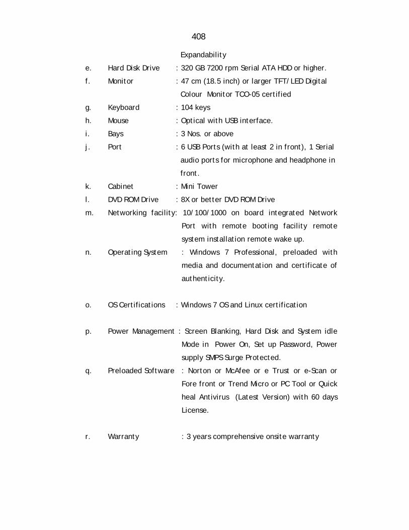
408
Expandability
e. Hard Disk Drive : 320 GB 7200 rpm Serial ATA HDD or higher.
f. Monitor : 47 cm (18.5 inch) or larger TFT/LED Digital
Colour Monitor TCO-05 certified
g. Keyboard : 104 keys
h. Mouse : Optical with USB interface.
i. Bays : 3 Nos. or above
j. Port : 6 USB Ports (with at least 2 in front), 1 Serial
audio ports for microphone and headphone in
front.
k. Cabinet : Mini Tower
l. DVD ROM Drive : 8X or better DVD ROM Drive
m. Networking facility: 10/100/1000 on board integrated Network
Port with remote booting facility remote
system installation remote wake up.
n. Operating System : Windows 7 Professional, preloaded with
media and documentation and certificate of
authenticity.
o. OS Certifications : Windows 7 OS and Linux certification
p. Power Management : Screen Blanking, Hard Disk and System idle
Mode in Power On, Set up Password, Power
supply SMPS Surge Protected.
q. Preloaded Software : Norton or McAfee or e Trust or e-Scan or
Fore front or Trend Micro or PC Tool or Quick
heal Antivirus (Latest Version) with 60 days
License.
r. Warranty : 3 years comprehensive onsite warranty
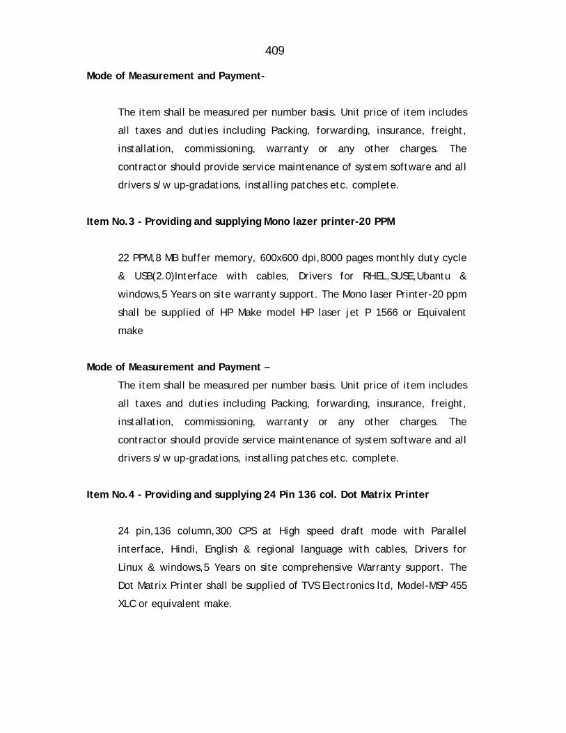
409
Mode of Measurement and Payment-
The item shall be measured per number basis. Unit price of item includes
all taxes and duties including Packing, forwarding, insurance, freight,
installation, commissioning, warranty or any other charges. The
contractor should provide service maintenance of system software and all
drivers s/w up-gradations, installing patches etc. complete.
Item No.3 - Providing and supplying Mono lazer printer-20 PPM
22 PPM,8 MB buffer memory, 600x600 dpi,8000 pages monthly duty cycle
& USB(2.0)Interface with cables, Drivers for RHEL,SUSE,Ubantu &
windows,5 Years on site warranty support. The Mono laser Printer-20 ppm
shall be supplied of HP Make model HP laser jet P 1566 or Equivalent
make
Mode of Measurement and Payment –
The item shall be measured per number basis. Unit price of item includes
all taxes and duties including Packing, forwarding, insurance, freight,
installation, commissioning, warranty or any other charges. The
contractor should provide service maintenance of system software and all
drivers s/w up-gradations, installing patches etc. complete.
Item No.4 - Providing and supplying 24 Pin 136 col. Dot Matrix Printer
24 pin,136 column,300 CPS at High speed draft mode with Parallel
interface, Hindi, English & regional language with cables, Drivers for
Linux & windows,5 Years on site comprehensive Warranty support. The
Dot Matrix Printer shall be supplied of TVS Electronics ltd, Model-MSP 455
XLC or equivalent make.
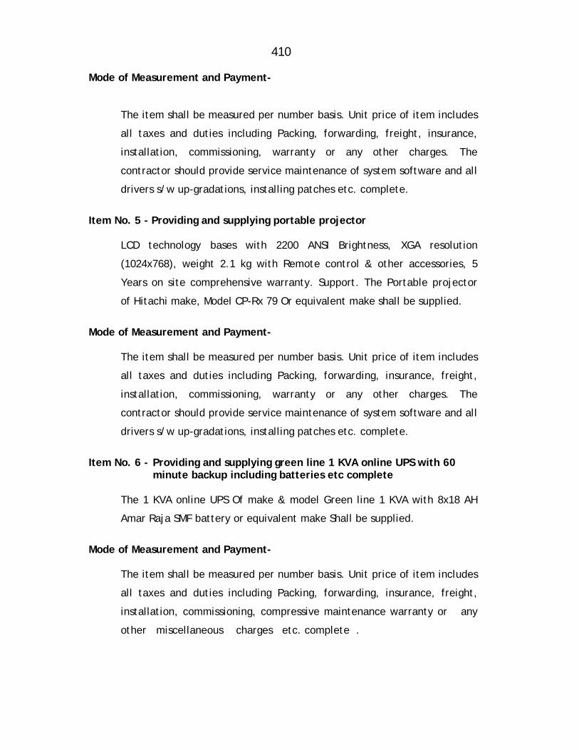
410
Mode of Measurement and Payment-
The item shall be measured per number basis. Unit price of item includes
all taxes and duties including Packing, forwarding, freight, insurance,
installation, commissioning, warranty or any other charges. The
contractor should provide service maintenance of system software and all
drivers s/w up-gradations, installing patches etc. complete.
Item No. 5 - Providing and supplying portable projector
LCD technology bases with 2200 ANSI Brightness, XGA resolution
(1024x768), weight 2.1 kg with Remote control & other accessories, 5
Years on site comprehensive warranty. Support. The Portable projector
of Hitachi make, Model CP-Rx 79 Or equivalent make shall be supplied.
Mode of Measurement and Payment-
The item shall be measured per number basis. Unit price of item includes
all taxes and duties including Packing, forwarding, insurance, freight,
installation, commissioning, warranty or any other charges. The
contractor should provide service maintenance of system software and all
drivers s/w up-gradations, installing patches etc. complete.
Item No. 6 - Providing and supplying green line 1 KVA online UPS with 60
minute backup including batteries etc complete
The 1 KVA online UPS Of make & model Green line 1 KVA with 8x18 AH
Amar Raja SMF battery or equivalent make Shall be supplied.
Mode of Measurement and Payment-
The item shall be measured per number basis. Unit price of item includes
all taxes and duties including Packing, forwarding, insurance, freight,
installation, commissioning, compressive maintenance warranty or any
other miscellaneous charges etc. complete .

411
90% payment shall be made after supply of above item with
satisfactory installation and commissioning. 10% payment release
with final bill.
Item No. 7 - Providing and supplying green line 2 KVA online UPS with 60 minute backup including Batteries etc complete.
The2 KVA online UPS Of make & model Green line 1 KVA with 8x65
AH Amar Raja SMF battery or equivalent make shall be supplied.
Mode of Measurement and Payment-
The item shall be measured per number basis. Unit price of item
includes all taxes and duties including Packing, forwarding,
insurance, freight, installation, commissioning, compressive
maintenance warranty or any other miscellaneous charges etc.
complete. 90% payment shall be made after supply of above item
with satisfactory installation and commissioning. 10% payment
release with final bill.
Item No. 8 - Providing and supplying 8 port 10/100 Mbps and 1 port
10/100/1000 Mbps and SFP port, wire speed SNMP Managed, full duplex, layer 2 switch etc complete.
The item shall be supplied of HP A 3100-8 E I (JD 318 A) model or
equivalent make shall be supplied.
Mode of Measurement and Payment-
The item shall be measured per number basis Unit price of item
includes Packing, forwarding, freight, installation, commissioning,
maintenance warranty or any other charges. The contractor shall
provide service maintenance of system etc at no extra cost during
warranty period. 90 % payment shall be made after supply of above
items with satisfactory installation &, commissioning. 10% payment
shall be released with final bill.

412
Item No 9- Supplying and erecting split type Room Air Conditioning unit 1.5 T.R., 5 star capacity etc complete.
Scope
Supplying, erecting and testing split type air conditioner of specified TR
capacity, conforming to IS:1391 having one/two air handling units Hi-
wall/ceiling (suitable for false ceiling) mounting type having cooling unit
and the outdoor condensing unit connected with 12/9 mm copper piping
up to 8 meter duly insulated and 3 core copper flexible cord of required
length etc. with stand for condensing unit, complete with t4esting etc.
(conforming to IS:1391 Part-I and Part-II with all amendments as per the
Bee) suitable for operation on single phase, AC supply 230, 250 Volts 50
Hz. Using best quality compressor, and fitting in the position as per site
situation and as directed by site engineer, duly connected to supply and
marking of Sr.No. and date of erection.
The AC unit shall be capable of performing following functions.
Cooling
Dehumidifying
Air circulating
Air filtering
Ventilation
The split type AC should be of reputed make and minimum 5 star rating
as directed by Engineer-in-Charge.
Material
Compressor
The air conditioners shall be fitted with hermetically sealed type
suction cooled reciprocating or discharge cooled rotary compressor (as
applicable), compressor unit operating on Refrigerant R-22 with suitable
rated capacitor start electric motor. It shall be equipped
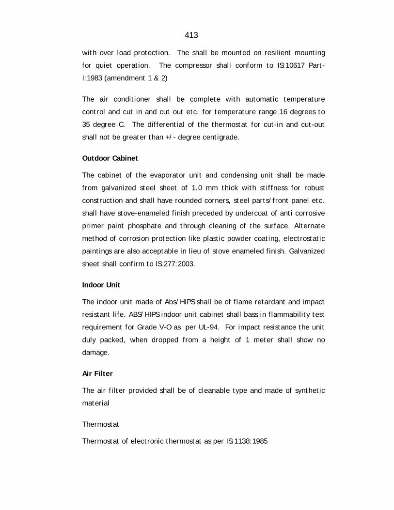
413
with over load protection. The shall be mounted on resilient mounting
for quiet operation. The compressor shall conform to IS:10617 Part-
I:1983 (amendment 1 & 2)
The air conditioner shall be complete with automatic temperature
control and cut in and cut out etc. for temperature range 16 degrees to
35 degree C. The differential of the thermostat for cut-in and cut-out
shall not be greater than +/- degree centigrade.
Outdoor Cabinet
The cabinet of the evaporator unit and condensing unit shall be made
from galvanized steel sheet of 1.0 mm thick with stiffness for robust
construction and shall have rounded corners, steel parts/front panel etc.
shall have stove-enameled finish preceded by undercoat of anti corrosive
primer paint phosphate and through cleaning of the surface. Alternate
method of corrosion protection like plastic powder coating, electrostatic
paintings are also acceptable in lieu of stove enameled finish. Galvanized
sheet shall confirm to IS:277:2003.
Indoor Unit
The indoor unit made of Abs/HIPS shall be of flame retardant and impact
resistant life. ABS/HIPS indoor unit cabinet shall bass in flammability test
requirement for Grade V-O as per UL-94. For impact resistance the unit
duly packed, when dropped from a height of 1 meter shall show no
damage.
Air Filter
The air filter provided shall be of cleanable type and made of synthetic
material
Thermostat
Thermostat of electronic thermostat as per IS:1138:1985
414
Piping
Suction line
Liquid line : Copper tubing of min 0.70 mm thickness and of suitable diameter as per manufacturer design.
Drain pipe : 15 mm dia flexible PVC pipe. Connection Cable Suitable capacity 3 core PVC insulated FRLS copper wire to be electrically
connected to both the units.
Paint: Superior quality enamel paint of specified colour. Remote Control: Remote control (Cordless) shall be provided with one On/Off timer selecting Fan
speed (Three speeds) and setting up of temperature.
Drain Pipe: Drain pipe (15 mm dia flexible PVC pipe) Method of Construction
The installation shall comprises of following work
Mounting/Fitting indoor and outdoor units at the respective locations on provided MS stands with necessary hardware’s
Laying refrigerant piping of required length and connecting both the units
after drilling hole/holes in the wall if required dia meter of the copper tubing shall not be less than and diameter of required size having threading etc.
Insulating the suction pipe with expanded polyethylene of foam 5mm
thubing
Laying 15 mm drain pipe to throw out the condensate water formed in the indoor unit
Leak testing of the entire system
Charging refrigerant gas in the unit

415
Suitable electric wiring between indoor and outdoor unit shall be provided.
Testing and giving satisfactory trials.
Mode of measurement & payment
The unit shall be counted on number basis.
80% payment shall be made after supply 10% after satisfactory installation at site 10% after satisfactory completion of work.
Item No 10- Supplying, Erecting and Commissioning of Diesel generating set
with AMF Panel etc complete
Providing DG set at site, carrying out all preparatory works, assembling,
installing, making adjustments conforming to pre-commissioning
requirement as per manufacturer’s instructions, commissioning final
testing, putting into operation and handling over the complete system of
DG set including inspection from inspectorate office. The work include
necessary minor civil works including opening on wall/slab / floor and
making good as it was etc. comprehensive maintenance of the DG set for
one year from date of commissioning.
Material
Diesel Generator set with continuous rating, 3 phase, 415 V, 50 cycles, AC
supply of specified capacity, comprising of totally enclosed air/water
cooled diesel engine with standard control panel and toolkit.
Diesel Engine
The engine shall be of standard design of original manufacturers. It
should be a totally enclosed air/water cooled diesel engine with 4 stroke
multi cylinder developing suitable BHP (As per Table) for giving power
rating of (As per table) at the load terminals of
416
alternator at 1500 RPM at armature temperature of 40oC for height at
1000 meter above MSL at 50% RJ. The engine shall be capable of
delivering specified power at variable loads for PF of 0.8 (lag) with 10%
over load available in excess of specified output for one hour in every 12
hours. The average load factor of the engine over period of 24 hours
shall be 0.85 for power output. The engine shall conform to IS:10000 and
Amended upto date.
The engine shall be fitted with following accessories.
1. Dynamically balanced by wheel 2. Necessary flexible coupling and guard for alternator and engine
applicable 3. Lubricating oil cooler 4. Air cleaner Dry Bath type 5. Lubricating oil pressure gauge 6. Lubricating oil filter with replicable element. 7. Dry exhaust manifold with suitable exhausts heavy duty residential type
exhaust silencer and vertical hot air duct both logged with asbestos role exhaust piping of required length to reduce noise level.
8. 12/24 V Electric starting equipment complete with standard batteries, dynamo, cut-out, ammeter, necessary wiring, self starter etc.. The system shall be capable of starting D.G. set within 20 to 30 second even in winter condition with an ambient temperature down to 0oC.
9. Mechanical Governor of Class A2 for up to and including 20 kVA capacity and electronic governor of Class A1 for capacity above 20 kVA shall be provided as per standard design of manufacturer. Governor shall be a self contained unit capable of monitoring speed.
10. Radiator. 11. Daily fuel tank
Daily fuel service tank of minimum capacity of 100 liters fabricated from
MS sheet with inlet, outlet connections air vent tap, drain plug and level
indicator (gauge) MS fuel piping from tank to engine with valves, unions,
reducers, flexible hose connection and floor mounting pedestals, twin
fuel filter. The location of the tank shall depend on standard
manufacturers design.
417
Engine Control Panel Engine control panel should be fitted with following accessories/indicators and
shall have display.
Start/stop key switch Lube oil pressure indication Water temperature indication RPM indication Engine hours indications Battery charging indication Low lube oil trip indication High water temperature indication Over speed indication
Battery Charger
The battery charger shall be of Trickle and Boost type, and suitable to
change required number of batteries at 12 V/24 complete with
transformer, rectifier, charge rate selector switch, indicating ammeter,
voltmeter, battery over charging protection with audible alarm.
Connections between the battery charger and batteries shall be provided
with suitable copper leads with lugs.
Battery
Battery capacity and copper cable sizes of various engine capacities shall
be as per the details given in table. Cable sizes shown are for maximum
length of 2 m length, if higher size of cable is required, it shall be
selected in such a way that voltage drop does not exceed 2 V.
Battery Capacity and Copper cable sizes of various Engine capacities.
Sr. No. DG Set Capacity Battery
capacity (AH) Copper cable size in mm2
Electrical system (Voltage)
1. Upto 25 kVA 88 35 12
418
For AMf application a static battery charger working on mains supply
recommended to keep the batteries charged at all time.
Alternator:
Alternator of specified rating, 415 Volts, 1500 RPM, 3 Ph., 50 Hz. AC
supply with P.F 0.8 lagging at 40oC armature temperature for height 1000
mtr. Above MSL at 50% RH alternator shall be brush loss type self
regulated having static excitation system having capacity of desired
output confirming to IS:4722:1968 with automatic voltage regulation + 5%
operated voltage from no load to full load, two numbers of earth,
terminal on opposite sides. Terminal box shall be suitable for
underground cables and same shall be with standard mechanical and
thermal stresses developed due to any short circuit at the terminals. The
alternator shall be in accordance with following standard.
IS:4722 The performance of rotating electric machine
IS:4889 Rules for method of declaring efficiency of electrical
machine
IS:13364 Part-I:1992 Alternator-voltage regulation upto 20 kVA
IS:13364 Part-IIL1992 Alternator voltage regulation above 20 kVA to 80
kVA.
Performance
Voltage dip shall not exceed 20% of the rated voltage for any step load or
transient load as per IS:8528 (Part-I. The winding shall not develop hot
spots exceeding safe limits due to unbalance of 20% between any two
phases from no load to full load.
The performance characteristics of the alternator shall be as below: a) Efficiency at full load 0.8 PF
i) Upto. 25 kVA not less than 82%
ii) Above 25 kVA and upto 62.5 kVA not less than 86%
iii) Above 62.5 kVA/upto 250 kVA not less than 90%
iv) Above 250 kVA not less than 93%
419
b) Total Distortion factor Less than 3%
i) 10% overload One hour in every 12 hour of continuous operation
ii) 50% overload 15 seconds
Common Base Plate
Engine and alternator shall be coupled by means of flex plate/flexible
coupling as per manufacturer standard design and both units shall be
mounted on a common base plate together with all auxiliaries to ensure
perfect alignment of engine and alternator with minimum vibration. The
base plate shall be suitable for installation on suitable anti-vibration
mounting system comprising of 5 anti-vibration pads duly provided.
Control Panel
Floor/Wall mounted control panel box comprising of voltmeter, ammeter,
selector, switches MCCB/MCB of adequate capacity, indicator lamp duly
wired with HRC fuses. Alternator and control panel shall be connected
with provided suitable capacity armored cable with necessary cable
glands and lugs etc.
Exhaust System
It shall comprises of following parameters
Exhaust system should create minimum back pressure.
Smooth bends shall be used for minimizing the back pressure
Minimum number of bends shall be used for minimizing the back
pressure.
Pipe sleeve of larger diameter should be used while passing the
pipe through concrete wall and gap shall be filled with felt lining.
420
Exhaust piping inside the acoustic enclosure/Generating set room
should be lagged with asbestos rope and covered with aluminimum
sheet cladding to avoid heating of the area.
Class ‘B’ MS pipes and long bend/elbows should be used.
The exhaust outlet should be in the direction of prevailing winds
and should not allow exhaust gases to enter air inlet windows etc.
Factory Testing DG set shall be tested in presence of Engineer-in-Charge or his authorized
representative in the factory for following before dispatch.
Full load trial for 12 hours. Fuel lubricating oil etc. shall be arranged by
the agency.
10% overload trial for one hour within 12 hrs. test.
Certificates Manufacturers test certificate for engine, alternator and of the set.
Necessary certificate for the engine model so selected along with
compliance of noise and emission norms as per latest CPCB guidelines for
DG set should be furnished from the manufacturer along with
manufacturers technical details.
Permission from Electrical Inspector.
Method of Construction The DG set with canopy shall be erected with due care and ensuring the
perforce level with the help of sprit level or provided cement concrete
foundation and connecting the provided earthing connections. The exhaust
system shall be connected to the exhaust manifold. After ensuring the filling of
fuel, lubricating oil and medium of coolant, the set shall be commissioned with
giving necessary full load trial or with the available load at site. The set shall
then be handed over to the department along with the installation report given
by the manufacturer and with all the necessary certificates and permission
obtained.
421
Rating of Alternator and minimum BHP of Engine.
S.No. kVA Capacity of
Alternator Minimum BHP of
diesel engine Average fuel consumption litre per hour at 100% load
1.
20
26
6.0
Automatic Mains Failure Panel (AMF) The work includes supplying, installing, testing and commissioning of automatic
mains failure control panel including auto by-pass, suitable for specified rating
of DG set complete with accessories and comprehensive maintenance of the
panel upto 1 year from the date of commissioning.
AMF panel shall comply following IS specification IS:2147:1962 Degree of protection
ISL4722 H.V. testing for panel
Material Panel shall consist of following: Power module a pair of electromechanically interlocked contactor for all
the phase/phases and neutral (For mains and generator) Overload relay for generator contactor, neutral contactor for mains and
generator Control and metering module: Line voltage monitor, Generator voltage
monitor, Ammeter, 3 times attempt to start facility MCB/MCCB of suitable rating for auto/manual operation. Auto/manual
switch Emergency stop push buttons. Manual start push button Frequency meter Engine hour and RPM meter (Taco meter) Two earthing studs Protection module: The engine shutdown in the unlikely event of low
lube oil, pressure, high cylinder head temperature, high water temperature (For water cooled engine)
Indicator with alarm for full/maximum load on generator.

422
Indicator for load of mains, load on DG set engine falls to start, Emergency stop.
Battery charger complete with transformer/rectifier, D.C. voltmeter and Ammeter selector switch for trickle, off and boost charging and current adjustment.
Main supply failure monitor Timers Fault reset push button.
Method of Construction AMF panel complete with relays-timers, set of CTs for metering and protection
and energy analyzer to indicate currents, phase and line voltages, frequency,
power factor, kWH, kVARH and provision for overload, short circuit, fault, under
frequency, control cabling from AMF panel to diesel engine and elsewhere if
required, complete with metering as per material list.
System Operation The above mentioned facilities provided shall be functional for following
operational requirements.
1. Auto mode
A line voltage monitor shall monitor supply voltage on each phase when the mains supply voltage fails completely or falls below set value (variable between 80 to 95% of the normal value) on any phase, the monitor module shall initiate start-up of diesel engine. To avoid initiation due to momentary disturbance, a time delay adjustment between 0 to 5 second shall be incorporated in startup intimation.
A three attempt starting facility shall be provided 6 seconds ON, 5
Second OFF, seconds ON, 5 second OFF, 6 seconds ON. If at the end of the third attempt, the engine does not start it shall be locked out of start and a master timer shall be provided for this function suitable adjustment timer are to be incorporated which will make it feasible to vary independently ON-Off setting period from 1 – 10 seconds, if alternator does not build up voltage after the first or second start as may be the case, further starting attempt will not be made until the starting facility is reset.
423
Once the alternator has built-up voltage, the alternator circuit breaker shall close connecting the load to the alternator. The load is now supplied by alternator. When the main supply is resorted and is healthy as sensed by the line voltage monitor setting, both for under voltage or unbalance, the system shall be monitored by a suitable timer which can be set between 1 minute to 10 minutes for the load to be transferred automatically to main supply.
The panel shall start the set in the event of fault condition of under voltage, over voltage, phase reversal, high frequency, neutral snapping, short circuit etc. on the mains side. If the above fault conditions arises, if the load is being fed from the DG set, then the panel start cut off the load from the set with an audible alarm, and the set shall run on no load.
2. Manual Mode
In a manual mode, it shall be feasible to start-up the generator set by the operator on pressing the start push button
Three attempt starting facility shall be operative for the start-up
function.
Alternator circuit breakers closing and trip operation shall also be through operator only by pressing the appropriate button on the panel and closed shall be feasible only after alternator has built up full voltage.
3. Test Mode
When under test mode, pressing of test button should complete the start up sequence simulation and engine shall be started
Engine shall build up voltage but the set shall not take load by closing
alternator circuit breaker when the load is on the mains, monitoring performance for voltage/frequency etc. shall be feasible without supply to load.
If during test mode, the power supply has failed, the load shall automatically get transferred on DG set
Bringing the mode selector to auto position shall shut down the set provided main supply is ON if the mains supply is not available at that time, the alternator shall take load.
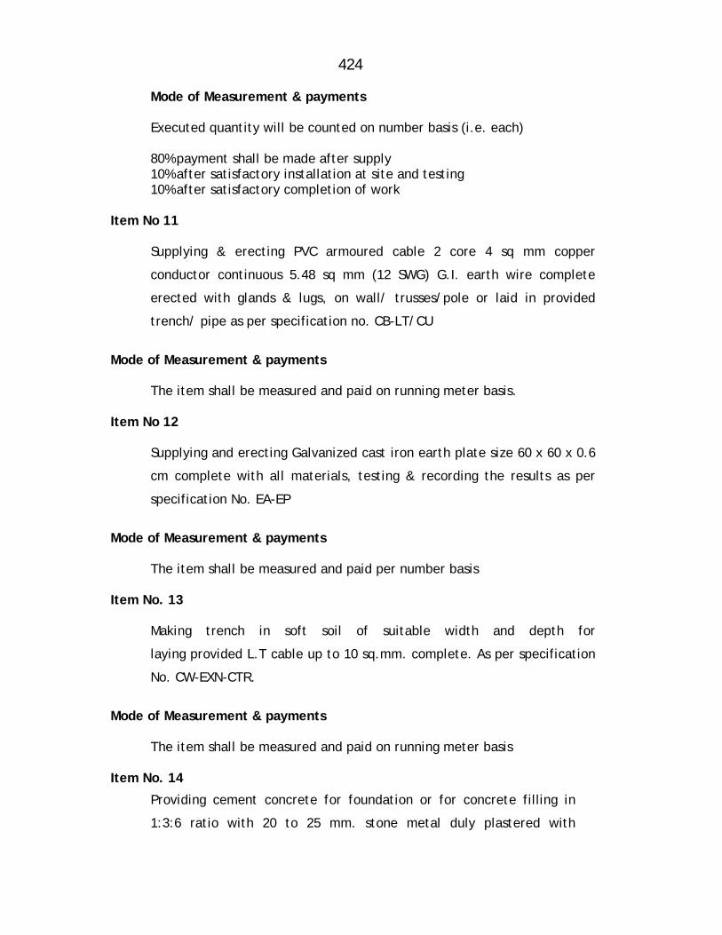
424
Mode of Measurement & payments
Executed quantity will be counted on number basis (i.e. each)
80% payment shall be made after supply 10% after satisfactory installation at site and testing 10% after satisfactory completion of work
Item No 11
Supplying & erecting PVC armoured cable 2 core 4 sq mm copper
conductor continuous 5.48 sq mm (12 SWG) G.I. earth wire complete
erected with glands & lugs, on wall/ trusses/pole or laid in provided
trench/ pipe as per specification no. CB-LT/CU
Mode of Measurement & payments
The item shall be measured and paid on running meter basis. Item No 12
Supplying and erecting Galvanized cast iron earth plate size 60 x 60 x 0.6
cm complete with all materials, testing & recording the results as per
specification No. EA-EP
Mode of Measurement & payments
The item shall be measured and paid per number basis Item No. 13
Making trench in soft soil of suitable width and depth for
laying provided L.T cable up to 10 sq.mm. complete. As per specification
No. CW-EXN-CTR.
Mode of Measurement & payments
The item shall be measured and paid on running meter basis Item No. 14
Providing cement concrete for foundation or for concrete filling in
1:3:6 ratio with 20 to 25 mm. stone metal duly plastered with
425
necessary curing for pole muffing or any other purposes. ( l = 2.5 m,W
= 1.5 m, H = 0.5 m )
Mode of Measurement & payments The item shall be measured and paid on Cubic meter basis Item No. 15:- Supply, installing, UTP networking CAT6 cable suitable for LAN/WAN/Computer
networking as directed by Engineer in charge.
Mode of Measurement & payments The item shall be measured and paid on running meter basis.

426
MAHARASHTRA JEEVAN PRADHIKARAN
MAHARASHTRA JEEVAN PRADHIKARAN W.M. CIRCLE, PANVEL
MAHARASHTRA JEEVAN PRADHIKARAN W.M. DIVISION , AMBERNATH NAME OF WORK: Augmentation to Ambernath Water Supply Scheme
Tal. Ambernath, Dist. Thane Construction of C.C. weir at Chikhloli Dam, Designing,
constructing & commissioning 7.20 ML capacity WTP at Chikhloli, lowering, laying and jointing D.I.K-7/K-9 pipes for rising main/gravity main/Transmission main/distribution system, construction of R.C.C. sump and pump house, construction of 8 nos. of RCC ESRs at various places with compound wall, construction of Consumer Redressal Centre with computerization, Railway crossing work, Repairs to Belivali MBR etc. complete.
ITEMWISE DETAILED SPECIFICATIONS SUB WORK NO. 11: DESIGNING AND CONSTRUCTING CONSUMER
REDRESSAL CENTRE AND BILL COLLECTION CENTERS WITH ELECTRIFICATION AND OTHER ALLIED WORKS IN AMBERNATH CITY
The contractor shall quote his offer in Schedule ‘B’ for the complete work
of constructing consumer Redressal center & bill collection center to be
carried out as per his own design based on given date i.e. he shall tender
the offer in Schedule ‘B’ for construction of required size with his own
design and drawings. The design shall be got checked from the institutes
like Govt. Engineer College. Ramarks shall be complied and scrutiny
charges shall be borne by the contractor.
1. The structural design of consumer Redressal center & bill collection
center shall conform to the following standard specification and
codes of practice of IS.
IS:456 Code of practice for plain and reinforced concrete (latest
edition)
a) IS:875 Code of practice for structural safety of building loading
standards. (Latest edition).
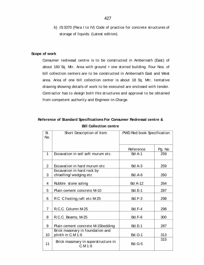
427
b) IS:3370 (Para I to IV) Code of practice for concrete structures of
storage of liquids. (Latest edition).
Scope of work
Consumer redressal centre is to be constructed in Ambernath (East) of
about 160 Sq. Mtr. Area with ground + one storied building. Four Nos. of
bill collection centers are to be constructed in Ambernath East and West
area. Area of one bill collection center is about 18 Sq. Mtr. tentative
drawing showing details of work to be executed are enclosed with tender.
Contractor has to design both this structures and approval to be obtained
from competent authority and Engineer-in-Charge.
Reference of Standard Specifications For Consumer Redressal centre &
Bill Collection centre
Sr. No.
Short Description of Item PWD Red book Specification
Reference Pg. No 1 Excavation in soil soft murum etc. Bd A-1 259
2 Excavation in hard murum etc Bd A-3 259
3 Excavation in hard rock by chiselling/wedging etc Bd.A-6 260
4 Rubble stone soling Bd A-12 264
5 Plain cement concrete M-10 Bd.E-1 287
6 R C C footing,raft etc M-25 Bd.F-3 298
7 R.C.C. Column M-25 Bd.F-4 298
8 R.C.C. Beams, M-25 Bd.F-6 300
9 Plain cement concrete M-15bedding Bd.E-1 287
10 Brick masonary in foundation and plinth in C.M 1:6 Bd.G-1 313
11 Brick masonary in superstructure in C.M 1:6 Bd.G-5
315
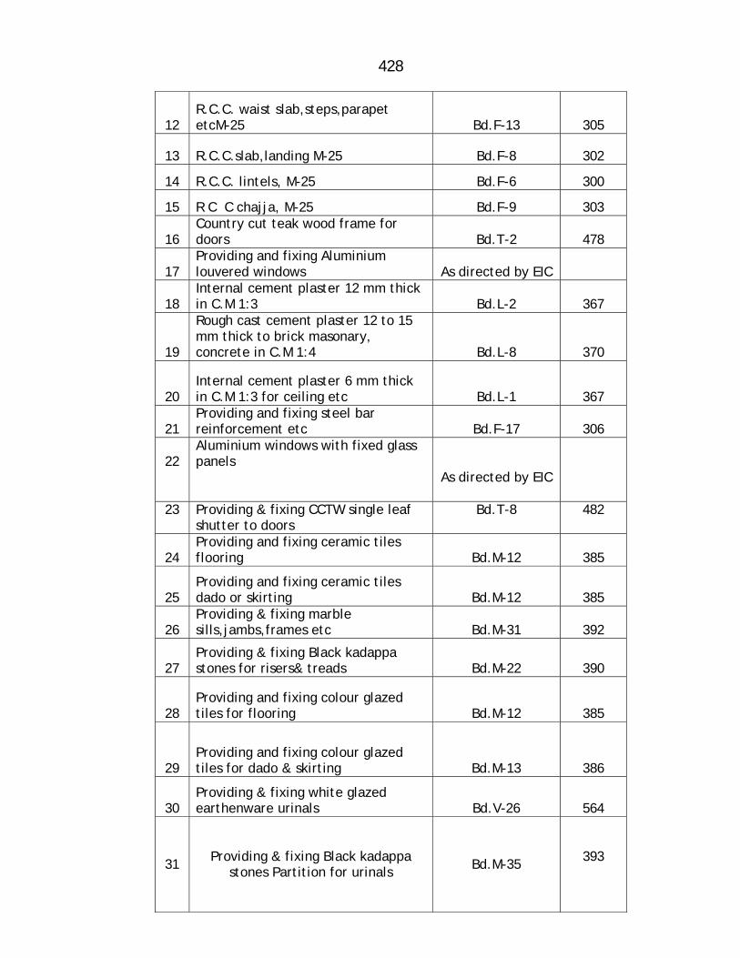
428
12 R.C.C. waist slab,steps,parapet etcM-25 Bd.F-13 305
13 R.C.C.slab,landing M-25 Bd.F-8 302
14 R.C.C. lintels, M-25 Bd.F-6 300
15 R C C chajja, M-25 Bd.F-9 303
16 Country cut teak wood frame for doors Bd.T-2 478
17 Providing and fixing Aluminium louvered windows As directed by EIC
18 Internal cement plaster 12 mm thick in C.M 1:3 Bd.L-2 367
19
Rough cast cement plaster 12 to 15 mm thick to brick masonary, concrete in C.M 1:4 Bd.L-8 370
20 Internal cement plaster 6 mm thick in C.M 1:3 for ceiling etc Bd.L-1 367
21 Providing and fixing steel bar reinforcement etc Bd.F-17 306
22
Aluminium windows with fixed glass panels
As directed by EIC
23
Providing & fixing CCTW single leaf shutter to doors
Bd.T-8
482
24 Providing and fixing ceramic tiles flooring Bd.M-12 385
25 Providing and fixing ceramic tiles dado or skirting Bd.M-12 385
26 Providing & fixing marble sills,jambs,frames etc Bd.M-31 392
27 Providing & fixing Black kadappa stones for risers& treads Bd.M-22 390
28 Providing and fixing colour glazed tiles for flooring Bd.M-12 385
29 Providing and fixing colour glazed tiles for dado & skirting Bd.M-13 386
30 Providing & fixing white glazed earthenware urinals Bd.V-26 564
31 Providing & fixing Black kadappa stones Partition for urinals Bd.M-35
393
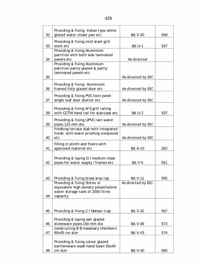
429
32 Providing & fixing Indian type white glazed water closet pan etc Bd.V-20 559
33 Providing & fixing mild steel grill work etc Bd.U-1 537
34
Providing & fixing Aluminium partition with both side laminated panels etc As directed
35
Providing & fixing Aluminium partition partly glazed & partly laminated panels etc As directed by EIC
36 Providing & fixing Aluminium framed fully glazed door etc As directed by EIC
37 Providing & fixing PVC twin panel single leaf door shutter etc As directed by EIC
38 Providing & fixing M S grill railing with CCTW hand rail for staircase etc Bd.U-2 537
39 Providing & fixing UPVC rain water pipes 110 mm dia As directed by EIC
40
finishing terrace slab with integrated finish with water proofing compound etc As directed by EIC
41 filling in plinth and floors with approved material etc Bd.A-10 262
42 Providing & laying G I medium class pipes for water supply /frames etc Bd.V-5 551
43 Providing & fixing brass stop tap Bd.V-11 555
44
Providing & fixing Sintex or equivalent high density polyethylene water storage tank of 2000 litres capacity
As directed by EIC
45 Providing & fixing C I Nahani trap Bd.V-32 567
46 Providing & laying salt glazed stoneware pipes 150 mm dia Bd.V-39 573
47 constructing B B masonary chembers 60x45 cm size Bd.V-43 574
48
Providing & fixing colour glazed earthenware wash hand basin 55x40 cm size Bd.V-30 565
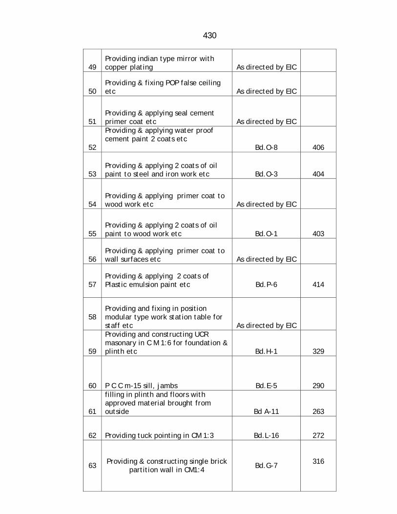
430
49 Providing indian type mirror with copper plating As directed by EIC
50 Providing & fixing POP false ceiling etc As directed by EIC
51 Providing & applying seal cement primer coat etc As directed by EIC
52
Providing & applying water proof cement paint 2 coats etc Bd.O-8 406
53 Providing & applying 2 coats of oil paint to steel and iron work etc Bd.O-3 404
54 Providing & applying primer coat to wood work etc As directed by EIC
55 Providing & applying 2 coats of oil paint to wood work etc Bd.O-1 403
56 Providing & applying primer coat to wall surfaces etc As directed by EIC
57
Providing & applying 2 coats of Plastic emulsion paint etc
Bd.P-6
414
58
Providing and fixing in position modular type work station table for staff etc As directed by EIC
59
Providing and constructing UCR masonary in C M 1:6 for foundation & plinth etc Bd.H-1 329
60 P C C m-15 sill, jambs Bd.E-5 290
61
filling in plinth and floors with approved material brought from outside Bd A-11 263
62 Providing tuck pointing in CM 1:3 Bd.L-16 272
63 Providing & constructing single brick partition wall in CM1:4 Bd.G-7
316
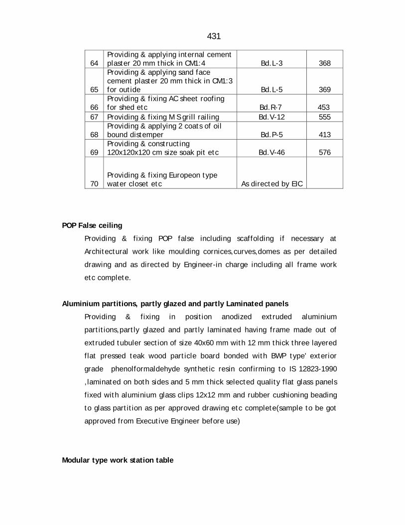
431
64 Providing & applying internal cement plaster 20 mm thick in CM1:4 Bd.L-3 368
65
Providing & applying sand face cement plaster 20 mm thick in CM1:3 for outide Bd.L-5 369
66 Providing & fixing AC sheet roofing for shed etc Bd.R-7 453
67 Providing & fixing M S grill railing Bd.V-12 555
68 Providing & applying 2 coats of oil bound distemper Bd.P-5 413
69 Providing & constructing 120x120x120 cm size soak pit etc Bd.V-46 576
70 Providing & fixing Europeon type water closet etc As directed by EIC
POP False ceiling
Providing & fixing POP false including scaffolding if necessary at
Architectural work like moulding cornices,curves,domes as per detailed
drawing and as directed by Engineer-in charge including all frame work
etc complete.
Aluminium partitions, partly glazed and partly Laminated panels
Providing & fixing in position anodized extruded aluminium
partitions,partly glazed and partly laminated having frame made out of
extruded tubuler section of size 40x60 mm with 12 mm thick three layered
flat pressed teak wood particle board bonded with BWP type' exterior
grade phenolformaldehyde synthetic resin confirming to IS 12823-1990
,laminated on both sides and 5 mm thick selected quality flat glass panels
fixed with aluminium glass clips 12x12 mm and rubber cushioning beading
to glass partition as per approved drawing etc complete(sample to be got
approved from Executive Engineer before use)
Modular type work station table
432
Providing & fixing in position Modular type work station table for staff
made out of 19 mm marine plywood for top supported on low height
partition with 1 mm thick laminate on top. Edges of top surface finished
with 25x25 mm thick wooden moulding finished with melamine polish of
approved shade or with posform laminate, including Pedestal with drawers
made of 19 mm thick marine grade plywood as shown in drawing, pedestal
finish with laminate from external surface & 1 mm thick laminate on
internal surface all complete with necessary wooden members finished
with melamine polish, footrest finished in laminate with melamine polish
including keyboard tray with mouse pad, CPU Trolly/unit.Pedastal,all
hardware of approved make all as per drawing & as per instructions of
Engineer in charge.
Aluminium fully glazed door
Providing & fixing anodized aluminum fully glazed doors including door
frame, with powder coating 5 mm thick sheet glass necessary fixtures &
fastenings, neoprene type rubber gaskets as per IS standard & detailed
drawing etc complete
Aluminium louvered windows
Providing and fixing in position aluminium louvered windows/ ventilators
(IS std.) of various sizes with powder coating as per detailed drawings and
specifications including aluminium frames 80 x 38 mm box type 5 mm
thick sheet glass louvers, clips / rubber plain P.V.C.. gaskets of approved
quality etc. complete.. (Sample to be got approved from Ex. Engineer
before use)
Aluminium Fixed glass window
Providing and fixing in position anodized extruded moulded aluminium
fixed glass panel window having frame made out extruded tubular section
of size 63 x 38mm x 2.00mm thickness (wt. 1.054 kg/Rmt.) mechanically
assembled at corners with glazing, beading of angle 25 x 25 x 1.60mm
thick (wt 0.21 kg/Rmt.) including plain sheet glass 5.5mm thick with
rubber gasket and wooden encasement wherever necessary etc. as per
approved drawing and specification etc. complete as directed drawing and
specification etc. complete as directed by Engineer in charge.
433
European type coloured glazed earthenware water closet pan
Providing and fixing European type coloured glazed (as per IS Std.)
earthenware water closet pan with Bekelite seat and lid with chromium
plated brass hinges and rubber buffers including UPVC soil and vent pipe
upto the outside face of wall, 10 litre UPVC low level tank flushing
cistern, 32 mm. dia. UPVC flush pipe with fittings, and clamps 20 mm dia.
UPVC over flow pipe with mosquito proof couplings, pointing to exposed
pipe and cutting and making good to the wall and floor testing etc.
complete. (Prior approval of sample and brand by Ex. Engineer is
necessary
Syntax water storage tank
Providing hoisting and fixing in position sintex or equivalent high density
polyethylene UV stabilized conforming to I.S.12701, water storage tank
with necessary connections, testing & all required accessories etc.
complete. (Prior approval of sample by Ex. Engineer is necessary before
use.)
Wash Hand Basin
Providing and fixing White glazed with bottle trap earthenware Wash
Hand Basin of 55x40 cm size including cold water piller taps, brackets,
rubber plugs and brass chain, stop tap, chromium plate bottle trap and
necessary pipe connections including UPVC waste pipe and trap upto the
outside face of the wall, making good the damaged surface, testing etc.
complete.
PVC door shutter
Providing and fixing PVC multi leaf door shutter of approved colour /
lamination made out of extruded rigid PVC hollow section PW2459 shutter
frame of size 24 x 59 mm having double wall construction as vertical styles,
top & bottom rails and middle lock rails of size 24 x 100 mm and the panel
434
in PW20200 multi chamber hollow plastic section of size 20 x 200 joined
each other by tongue and groove interlocking system duty inserted in
shutter frames and all shutter frames, lock rails, styles reinforced by
polymer inserted inside for fixing of hinges, aldrops, tower bolts and
baby latch etc. All corners should be machine cut joined each other by
metal screw after inserting rigid L bracket PVC reinforced of size 100 x
200 mm including synthetic metal / alluminium with powder coating,
fixtures and fastenings remarking , damage surface etc. complete.
Mirror
Providing mirror of approved Indian quality copper plated with 100 mm
thick plywood backing and fixed in the masonry etc. complete
SPECIFICATION FOR ELECTRIFICATION 1. POINT WIRING CONCEALED TYPE:-
Providing, Point wiring for light/fan/bell concealed type with all
required approved material as specified in specification No. WGPA / CW
of PWD electrical specification and as directed by the Engineer-in-
Charge
All wiring shall be tested with 500V Meggar between phases, phase –
neutral and to earth IR value shall not be less than 1M-ohm.Earth
continuity shall be ensured at all earth terminals of plug outlets and at
earth terminals of metal enclosures. Polarity test shall be carried out for
ensuring the correct polarity in the plug.
2. POINT WIRING IN PVC TRUNKING ( Casing & Capping)
Providing all required approved material as specified in specification No.
WG-PW/SW of PWD electrical specification book and as directed by the
Engineer-in-Charge

435
All wiring shall be tested with 500V meggar between phases, phase –
neutral and to Earth.IR value shall not be less than 1M-ohm.Earth
continuity shall be ensured at all earth terminals of plug outlets and at
earth terminals of metal enclosures. Polarity test shall be carried out for
ensuing the correct polarity in switch and plug.
3. PLUG POINT WIRING :-
a) Point wiring for plug shall be on concealed type light/fan
switchboard with copper wire
and with modular accessories etc complete as per direction of the
Engineer-in –charge.
b) Point wiring for plug shall be on light/fan/bell switchboard with
copper wire and with
required accessories etc complete as per direction of the Engineer-in
–charge.
4. INDEPENDENT POINT WIRING CONCEALED TYPE:--
Providing Independent Point wiring concealed type with all required
approved material as specified in specification No. WG-PW/SW of PWD
electrical specification book and as directed by the Engineer-in-Charge.
All wiring shall be tested with 500V meggar between phases, phase –
neutral and to earth IR value shall not be less than 1M-ohm.Earth
continuity shall be ensured at all earth terminals of plug outlets and at
earth terminals of metal enclosures.
Polarity test shall be carried out for ensuring the correct polarity in the
plug.
436
5. MAINS OF 2 x 2.5 MM²
a) Providing and erecting mains of 2 x 2.5 mm² FR grade insulated
stranded / solid copper conductor electrolytic tough pitch (ETP) grade,
having insulation of 1.1 kV grade, ISI marked, of required colour coding
as per specified in specification No. WG-MA/BW of PWD electrical
specification book and as directed by the Engineer-in-Charge.
Open Wire bunch:
Open wires shall be erected with due care so as to avoid chances of any
mechanical injury. Harnessing shall be done with required material in an
approved manner in panel boards or where ever necessary. For covering
lead wires flexible conduit shall be used with gland as per necessity.
Testing:
Insulation resistance test:
All wiring shall be tested with 500V meggar between phases, phase –
neutral and to Earth.
IR value shall not be less than 1M-ohm.
Polarity Test:
Test shall be carried out for ensuring the correct polarity in switch and
plug.
b) Earthing Wire: Providing and erecting earthing wire of 1.5 mm² FR
grade insulated stranded / solid copper conductor electrolytic tough
pitch (ETP) grade, having insulation of 1.1 kV grade, ISI marked, earth
continuity shall be ensured between termination points of earth wire.
437
Polarity Test:
Test shall be carried out for ensuring the correct polarity in switch and
plug.
c) Concealing of PVC conduits, erecting / laying In wall or in flooring
shall be by making chases / grooves / entries as per approved method
of construction along with of all required material including hardware
such as ‘U’ nails, binding wire, fish wire; accessories such as PVC / MS
junction boxes / inspection boxes, check-nuts, flexible PVC pipe, glands,
drawing fish-wires and making all piping rigid, refinishing the surface
with cement mortar, removing debris from site.
There shall be knockout holes in required numbers and dia. for entry of
conduit pipes and arrangement to fix cover plate on it.
Hardware such as ‘U’ nails, plumbing and general use nails of required
sizes, washers, check-nuts, steel binding wire 20g, steel fish wire, etc
Other material for Surface finishing such as Cement, sand, putty, and
water. Work shall be done in co-ordination with civil work to suite final
approved layout. Size of conduit shall be correct depending on number
of wires to be drawn. (Table No 1/2 for PVC conduits) Separate pipe
shall be used for each phase in 1-ph distribution and for power and light
distribution and also for wiring for other utilities like data, telephone,
TV cabling, etc. for which the distance between pipes shall not be less
than 300 mm or anti electrostatic partition is to be provided. Adequate
use of conduit accessories shall be made at required locations. Entries in
wall shall be at level of corresponding conduit with colour coding as per
Table No.1/4. (For Visual identification) Flexible conduits shall be used
at expansion joints.
Erection shall be done as per the layout finalized, with minimum sharp
bends, with junction boxes at angular junctions and for straight runs at
every 4.25m, in such manner so as to facilitate drawing of wires. All
bending of conduits shall be done with Bending Spring. Alljoints shall be
made rigid with resin.
438
Concealing of PVC Conduits In walls / flooring:
Chases shall be made in walls of adequate width, with cutter and
chiseling through it. Necessary finishing of the wall surface shall be
done. Work in flooring shall not disturb RCC work, Conduits of adequate
size shall be erected with use of appropriate accessories, and
‘U’ nails. All joints shall be made rigid with resin. Draw-in / inspection
boxes shall be fixed with check-nut, flush with surrounding surface and
earthed.
6. a) Supplying and erecting approved make square parabolic recess mirror
optic square / rectangular PL fitting suitable for 2 x 36 W compact fluo.
lamp with electronic ballast fixed in false ceiling as per specified in
specification No. FG-IDF/MOF of PWD electrical specification book and
as directed by the Engineer-in-Charge.
b) Supplying and erecting square type recessed down lighter suitable for
2x18 watts CFL,
as per specified in specification No. FG-IDF/DL1 of PWD electrical
specification book and as directed by the Engineer-in-Charge.
c) Supplying and erecting bulkhead fitting with fine finished cast as per
specified in specification No. FG-IDF/BHF of PWD electrical specification
book and as directed by the Engineer-in-Charge.
d) Supplying and fixing of Compact Fluorescent lamps with Pin type (PL
tube to be used with ballast), suitable for 230 volts, and of 36 wattage.
The lamp shall have life of 10000 burning hours and shall meet with the
requirements mentioned in Table No. 2.1/7. All lamps shall have pf
above 0.9.

439
Lamp material shall be based on fluorescent powder, with electrode.
Cap shall be Pin type/Screwed cap made from high grade Aluminium
sheet. The lamp shall be fixed at specified location as directed by site
engineer.
e) Supplying and fixing of Compact Fluorescent lamps with Pin type (PL
tube to be used with ballast), suitable for 230 volts, and of 18 wattage.
The lamp shall have life of 10000 burning hours and shall meet with the
requirements mentioned in Table No. 2.1/7. All lamps shall have pf
above 0.9.Lamp material shall be based on fluorescent powder, with
electrode. cap shall be Pin type/Screwed cap made from high grade
Aluminum sheet.
The lamp shall be fixed at specified location as directed by site
engineer.
f) Supplying and fixing of Compact Fluorescent lamps with adapter
(Retrofit – Instant Start type) suitable for 230 volts, and of 15 wattage.
The lamp shall have life of 10000 burning hours and shall meet with the
requirements mentioned in Table No. 2.1/7. All lamps shall have pf
above 0.9.Lamp material shall be based on fluorescent powder, with
electrode. cap shall be Pin type/Screwed cap made from high grade
Aluminum sheet.
The lamp shall be fixed at specified location as directed by site
engineer.
7 a) Supplying and erecting Ceiling fan of 1200 mm sweep with all
accessories and necessary materials, erected in hook/clamp as per
specified in specification No. FG-FM/BF of PWD electrical specification
book and as directed by the Engineer-in-Charge.
Testing:
After erection fan shall be tested by connecting to supply at all positions
of regulator.lso steadiness of fan shall be checked at full speed, so that
there is no wobbling.

440
b) The electronic step regulator shall be modular type ( One module ) ISI
mark suitable for ceiling fan duly erected on provided plate and box with
wiring connections complete.
8. Supplying & erecting MCB of single pole, 32 AMP ‘B’ series as per
specification No.SW-SWR/MCB of PWD electrical specification book and
as directed by Engineer-in-Charge.
9. Supplying & erecting galvanized cast iron earthing of size 60x60x6 cm
complete as per specification No.EA-EP of PWD electrical specification
book.
Testing:
The value of each earth electrode shall be measured by earth tester in
presence of site
Engineer and record to be submitted.
10 Providing and erecting cupboard for enclosing energy meter, cutout,
MCB etc. made from selected marine plywood planks 19 mm. thick duly
varnished/ painted from inside and from outside with brass hinges and
locking arrangement with suitable lock with duplicate keys. Cupboard
duly grouted with suitable size of iron work in wall at the bottom.
11 Supplying and erecting Iron clad cut out H.C. type 500V 63A approved
make erected on provided cupboard in an approved manner.
12 Supplying and erecting Exhaust fan of 300 / 400 RPM / 4000 CFM
capacity sweep with all accessories and necessary materials, suitable to
work on 230 V, AC supply 50 Hz, erected in position. Fan motor with
moisture proof treatment and E class insulation, ISI marked, conforming
to IS: 2312/67 with amendments 1 to 8. The fan mounting rings shall be
proper pre-treatment followed with at least two coats of primer; final
finish shall be with two coats of grey colour paint duly baked. The
connecting leads shall be brought out for making connections.
441
Superior quality enamel paint of specified colour shall be used for
marking Sr. No and date of erection.
The Exhaust fan complete with all above accessories and duly wired shall
be erected at
specified position, connected to the supply and tested.
Testing:
After erection fan shall be tested by connecting to supply. Also
steadiness and vibrations if any, of fan shall be checked at full speed, so
that there is no wobbling.

442
Obligatory Conditions for Consumer redressal centre &
Bill Collection centre
1) Consumer redressal centre is to be constructed in Ambernath with
ground plus one storeyed R C C framed structure as per general tentative
layout as given in enclosed drawing and as per directions of Engineer
in charge
2) The structure is to be designed by contractor at his own cost and get it
approved as mentioned in general conditions
3) After obtaining approval of Engineer in charge to the drawings and
design the proposal is to be submitted to local Authority for obtaining
Building construction permission and compliances of remarks if any. It is
the responsibility of the contractor to obtain the permission ,necessary
help required from departmental side will be provided.
4) The work is to be started only after permission is granted by local
Authorities.
5) The work is to be carried out as per standard specifications of P W D
and as per directions of Engineer in charge
6) The General scope of work involved is as under.
a) Excavation for foundation in all type of strata
b) Rubble stone soling 20 cm thick below column footings and below
flooring .
c) plain cement concrete 0.15 m thick in M-10 for foundation and
Plinth bedding
d) R.C C. M-25 for column footing,Columns,Beams,lintels,
,slabs,landings,Chajjas etc and TMT steel reinforcement
e) B B Masonary of 23 cm thick for walls in C M 1:6 in plinth and
superstructure. Height 3.2 m minimum each floor and 2.1 m for
head room
f) Door frames of C C T W
g) Aluminium lovoured windows 4 nos of 0.45x0.60 m sizein toilet
section
443
h) Internal cement plaster of 12 mm thick for inside area in C M
1:3,6 mm thick plaster to ceiling portion,and Rough cast cement
plaster externally12 t0 15 mm thick with water proffing compound
in C M 1:4
i) Anodized extruded moulded aluminium fixed glass panel windows
of required size as directed by Engineer in charge
k) Ceramic tiled flooring of 60x60 cm size tiles consumer redressal
center and computer hall,cabin and toilet block passage
l) Ceramic skirting of 0.15 m height
m) Colour marble slab for sills,jambs,frames for windows and opening
in staircase ( 0.23 m width.)
n) Black kadappa stone for risers and treads of staircase and main
door steps 25 to 30 mm thick
o) colour glazed tiles of 30x30 cm size for flooring in w.c and urinal
section and full height in w c and urinal section.
p) White glazed earthenware lipped back type urinals (3 nos )with
flushing cistern and polished black kadappa sone partition.
q) one no of Indian type white glazed earthenware 580mm water
closet pan in w c .
r) Mild steel grill work weighing 15 kg/sqm for 17 windows and 8 no
of opening in staircase
s) providing and fixing aluminium partions with both side laminated
panels in consumer redressal cell counter area of about 11.50 sqm
t) Providing and fixing aluminium partitions partly glazed and partly
laminated panels. Computer section about 17 sqm
u) Providing and fixing aluminium fully glazed door(1 No) of
size0.90x1.8 m for computer section.
v) PVC twin panelled sigle leaf door shutter(2 No) of size 0.9x1.8 m
for w c and urinal section

444
w) Mild steel grill railing weighing 20 kg per sqm withC C T W hand
rail of size 75x60 mm and sill of 75x25 mm for staircase
x) 110 mm dia UPVC rain water pipe -15 Rmt
xi) providing and fixing 15 mm dia (30 m)and 20 mm dia (40m)G I
pipe line for water supply with 4v brass stop taps
xii) Finishing terrace slab with water proofing compound and filling in
plinth with approved excavated materials
xiii) Providing hoisting and fixing sintex or equivalent make of 2000
litre capacity with necessary connection and testing
xiv) Providing and fixing nahani trap 3 no, providing and laying 150
mm dia salt glazed stone ware pipes about 30 m, B B masonary
chembers of 60x 45 cm size 5 No,
xv) Colour glazed wash hand basin of size 55x40 cm ( 2 No ),2 Indian
quality copper plated mirrors( 2 No)
xvi) providing and fixing POP false ceiling to halls of about 110 sqm
area
xvii) Inside painting 2 coats of plastic emultion with primer
coat,Outside 2 coats of water proof cement paint with seal
cement primer, Oil paint 2 coats tostructure steel work and iron
work , and wood work etc
xviii) Providing and fixing moduler type work station table(4 No) for
staff as per approved drawing and as directed by Engineer-in
charge
Electrification work(Consumer redressal center)
1) Point wiring for light/fan/bell etc in PVC conduit - 51 points
2) Point wiring for plug etc - 38 point
3) point wiring for independent plug cocelled type - 10 point
4) supply and errection mains with 2x2.5 sqmm f R copper wire - 100 m
5) supply and errection mains with 1.5 sqmm f R copper wire - 100 m
6) Chiselling wall/ floor with supply and errecting pvc conduit - 100 m
445 7) Square double parabolic recess/surface mirror optic - 23 No
square/rectagular PL fitting with eletronic ballast
8) Square type recessed/surface down lighter with reflecter - 6 No
and glass cover
9) Bulk head fitting suitable for integral CFL fixed on wall - 2 No
10) 2x36 W CFL bulb - 54 no
2x18 W bulb - 14No
10) Ceiling fan 1200 mm - 11 No
11) Moduler type electronic step regulater 2 module -11 No
12) Supplying, errecting and marking SPMCB 6 A to - 6 No
32 A B series (for lightuing)
13) Galvanized cast iron earth plate size 60x60x0.60 cm - 2 No
14) Cupboard for meter and switch - 1.25 sqm
15) Iron clod cutout h C type 500v 63 A - 1 No
16) Exhaust fan heavy duty 230 v - 1 No
All work shall be executed as per specifications enclosed and as directed by
Engineer in charge
Obligatory conditionsfor constructing 4 Bill collection centers in
Ambernath town
1) Bill collection centers are to be constructed at 4 locations given by MJP
as per general drawing given and as directed by Engineer in charge
2) The structure is to be designed by contractor at his own cost and get it
approved as mentioned in general conditions
3) The work is to be carried out as per standard specifications of P W D and
as per directions of Engineer in charge
4) The General scope of work involved is as under.
a) Excavation for foundation in all type of strata.

446
b) Rubble stone soling 0.23 m thick for foundation plinth and
platform etc
c) P C C m-15 for foundation bedding 10 cm thick
d) U C R masonary for foundation o.6 m wide and 0.45 m depth and
plinth 0.45 wide and 0.40 m depth minimum
e) P C C m-15 coping over U C R 10 cm thick
f) murum filling in plinth
g) B B Masonary walls in C M 1:6 (0.23 m thick and 3 m height)
h) cement tuck pointing in C M 1:3
i) B B masonary half brick partition wall in C M 1:4 for toilet and
parapet
j) RCC M-200 chajja,slab etc 12 cm thick
k) TMT steel reinforcement
l) 20 mm thick internal cwement plaster in CM 1:4 and sand face
plaster in CM 1:3 for outside
m) Door frames of C C T W
n) C C T W door shutter
o) Aluminium louvered window for toilet(0.4x0.50m)
p) Ceramic tiles flooring and skirting in toilet etc
q) Polished quota stone sills frames etc
r) Mild steel grill work to windows
s) Providing and laying G I medium class pipe 50 mm dia for frame
work
t) A C sheet roofing for shed
u) G I pipe railing
v) washable oil bound distemper 2 coats with primer etc
w) Outside painting of water proof cement paint etc
x) Oil painting to wood work and steel structure
xi) P V C Single leaf door shutter to toilet
xii) Orisa type water closet pan580 mm
xiii) providing and constructing soakpit of size 120x120x120 cm
447
xiv) Providing hoisting and fixing sintex or equivalent make of 2000
litre capacity
xiv) Providing and fixing nahani trap , providing and laying 150 mm
dia salt glazed stone ware pipes about , B B masonary chambers of
60x 45 cm size
xv) providing and fixing 15 mm dia and 20 mm dia G I pipe line for
water supply with brass stop tap
xvi) Providing and fixing white glazed wash hand basin etc 55x40cm
size
Electrification work (Bill Collection centers 4 No)
1) Point wiring for light /fan etc in PVC casing and caping etc - 16 NO
2) Point wiring for plug on board of light - 12 No
3) Square double parabolic recess/surface mirror optic - 4 No
square/rectangular PL fitting with electronic ballast
4) Ceiling fan 1200 mm - 4 No
5) Modular type electronic step regulator 2 module - 4 No
448
Contractor No. of corrections Executive Engineer
SCHEDULE OF PAYMENT The item of Consumer redressal centre and Bill Collection Centre is
for complete unit of work. The schedule of payment will be on lump
sum basis at the percentage specified below.
A) CONSUMER REDRESSAL CENTRE
1 Excavation, PCC, Footing, Soling & Col. upto G.L. 7% 2 Columns and beams upto and including roofs slab
a) At ground floor b) At 1st floor
15% 15%
3 B.B. Masonary with doors & window a) At ground floor b) At 1st floor
10% 10%
4 Staircase 2% 5. Plastering & flooring 12% 6. Grill work and Railing 2% 7. Plumbing with syntax tank & sanitation system with
inspection chamber 3.5%
8. Interior decoration such as false ceiling with furniture arrangement
14%
9. Painting and water proofing 2.5% 10 Electrification 6% 11 Misc. Work 1%
Total 100%
449
Contractor No. of corrections Executive Engineer
B) BILL COLLECTION CENTRE
1. Excavation, PCC, Soling, UCR for foundation,
coping & murum filling upto plinth
18%
2. B.B. masonary for superstructure 15%
3. R.C.C. Slab & Beams 9%
4. Plastering & Flooring 15%
5. Door & Window 10%
6. Grill work & Railing 5%
7. A.C. Roof Shade 9%
8. Water Supply & Sanitary System 10%
9. Painting & Misc. Work 2%
10 Electrification 7%
Total 100%
No change in percentage specified above shall accepted.
Partial completion of item as quoted above will not be
considered for payment in part.
450
Contractor No. of corrections Executive Engineer
MAHARASHTRA JEEVAN PRADHIKARAN
MAHARASHTRA JEEVAN PRADHIKARAN W.M. CIRCLE, PANVEL
MAHARASHTRA JEEVAN PRADHIKARAN W.M. DIVISION , AMBERNATH
NAME OF WORK: Augmentation to Ambernath Water Supply Scheme, Tal.
Ambernath, Dist. Thane. Construction of C.C. weir at Chikhloli Dam, Designing,
constructing & commissioning 7.20 ML capacity WTP at Chikhloli, lowering, laying and jointing D.I.K-7/K-9 pipes for rising main/gravity main/distribution system, construction of R.C.C. sump and pump house, construction of 8 nos. of RCC ESRs at various places with compound wall, construction of Consumer Redressal Centre with computerization, Railway crossing work, Repairs to Belivali MBR etc. complete
SUB WORK NO. 12: DESIGNING, PROVIDING, CONSTRUCTING &
COMMISSIONING 7.2 MLD WTP AT CHIKHLOLI
OBLIGATORYREQUIREMENTS OF THE WTP The water treatment plant shall be in RCC and designed by the Contractor at
his own cost with the following obligatory data.
OR-1 Rated Capacity The capacity of the plant as a whole, for individual units as per
Schedule-B and specifications. The plant shall be of 7.20 MLD
Capacity.
OR-2 Layout of Plant As per Contractor's design, within the boundaries of the enclosed
contour plan, the layout shall be such as would give the whole plant an
aesthetic appearance. It shall not, however, affect beauty of the
architectural treatment given to the face of the central filter house
building. The MJP reserves the right to modify the layout, if considered
necessary. The layout of plant shall indicate internal roads. The
451
Contractor No. of corrections Executive Engineer
layout of the plant shall be as compact as possible. The Contractor
shall have to construct the treatment plant for capacity 7.20 MLD and
in accordance with the detailed specifications.
OR-3 Scope of Work The scope of work shall be as per contract limit marked on layout and
as mentioned below –
The work shall start 15 m ahead of raw water inlet chamber as
specified in the specifications and end at the last manhole of drainage
system. In case of distribution from pure water sump distribution
outlet piping should be limited to 15 m excluding control valve. The
length of horizontal MS/CI pipe from the face of vertical inlet pipe to
inlet chamber shall be 15 m without any sluice valve. The design of
Contractor must include all units of Water Treatment Plant as per
Schedule-B.
OR-4 Levels G.L. of WTP site 44.00 M Lip of Aeration fountain 48.00 M LSL of sump at WTP 40.00 M are obligatory. The Contractor should ascertain the actual strata met
with though the trial pit results given. FSL of sump 44.00 M OR-5 Foundation i) The structure should be founded on hard strata and minimum
depth of excavation in hard strata shall not be less than 1.00 m. ii) The Contractor has to verify the bearing capacity during
execution and base the foundation suitably. iii) The offer of the Contractor shall include excavation for all the
units of the plant as per Schedule-B in all types of soft and hard strata by any or all means, including all leads and lifts involved in the work as per actual requirement at the site. It shall also
452
Contractor No. of corrections Executive Engineer
include bailing or pumping out water, right from commencement of work till its completion in all respects for the entire plant units as per Schedule-B. All machineries, T&P, manpower, etc. required for this job shall have to be provided by the Contractor at his own cost.
iv) All the structures should be checked for seismic zone IV action
for safety and stability. v) All the structure of the units as per Schedule-B shall be design
for necessary uplift pressure for entire area of the plant layout, if so insisted by the Engineer-in-Charge.
OR-6 Type of Construction Reinforced Cement Concrete : Cast in-situ. To be based on following ISI Specifications. i) IS:456 (latest edition), Water retaining structure/water
container shall be constructed in M-300 and remaining structures shall be constructed in M-250
ii) IS:3370:1965 Part-I, Part-II and Part-IV.
iii) IS:1893:1975 (Latest edition)
iv) IS:875:1964
v) National Building Code of Practice, Government of India Latest edition, Publication of ISI.
vi) Any other IS Specification, not mentioned above but relevant in
the design, construction, etc. shall be made applicable. For such application no extra claim shall be payable to the Contractor.
vii) IS:13920 for Seismic Zone – IV. OR-7 Construction The Construction shall be carried out as per (a) Relevant latest ISS; (b)
Abstract of specification given in Annexure-I incorporated as per
Standard Specification Book, 1972 edition, Government of Maharashtra
453
Contractor No. of corrections Executive Engineer
Publication (c) National Building Code of Practice; (d) Relevant
Chapter of PWD Hand book.
In case where alternatives are mentioned in publication for design as
well as construction purpose, the approval of the accepting authority
of the tender shall have to be obtained for the particular alternative
proposal to be used by the Contractor. If MJP does not agree to that
alternative, the Contractor shall have to adopt the alternative as
suggested by the MJP without extra cost.
OR-8 General Requirements to be provided for in all the Structures Besides Those Enumerated in Schedule-B and Specifications.
a) For Civil work For all civil works the requirements as laid down in Appendix-A General Specifications, of these tender document shall have to be scrupulously followed.
b) For Mechanical work
The requirements as laid down in Appendix-B of these tender document shall be essentially govern the offer of the Contractor.
c) For Electrical Works
The specification laid down in Appendix-C of these tender documents shall be binding on the Contractor wherever relevant.
d) For Architectural work
The offer should include architectural treatment to the entire plant structure to give an elegant look to the complete premises. The Contractor shall workout details so as to offer elegant look.
OR-9 Use of Steel for RCC Members as Reinforcement Tor steel of 415 grade and Mild Steel Grade-I shall only be
used as per design. The Contractor shall have to procure the
steel from open marked. The steel procured by contractor
shall be tested and the contractor shall produce
manufacturer’s test certificate without which it shall not be
accepted. Further the contractor shall arrange to get tested
any samples from steel brought at site by him in laboratory
454
Contractor No. of corrections Executive Engineer
at his cost and result should be submitted to the Maharashtra
Jeevan Pradhikaran. Defective steel brought by the
Contractor shall be rejected and will not be allowed to be
used. Test certificate starting the chemical composition and
characteristics of the product should also be produced.
At least 3 samples of each diameter should be tested from
every 5 MT or part thereof. Tests lots only be permitted to be used.
All reinforcement used for WTP should be with epoxy coating
as per detailed specification OR-10 Specific Requirement to be provided for in the Design of
hydraulic and building structures. a) All members of the structures in contact with water
shall be in RCC grade (M-30). In case of vertical walls or water retaining structures the portions of walls above FSL and slab covering or incubating water shall also be of the same grade as that of the portion below it. The minimum thickness of such member shall not be less than 15 cm or design requirements. This is not applicable for small channel walls, roofs, and flocculator wall of clariflocculator, which should satisfy the design requirements.
b) Wherever partition walls are provided in water
retaining structures, these shall be designed for the conditions with one compartment as full while adjacent as empty, wherever such condition is applicable.
c) The sidewalls of water retaining structures shall be
designed for the worst condition such as i) Tank full conditions without earth filling from
outside. ii) Tank empty conditions with submerged earth
pressure from out side. iii) There shall be no counter-force coming inside
the structures.
455
Contractor No. of corrections Executive Engineer
I) Aeration Fountain (Cascade Type)
a) Capacity (ultimate) 7.20 MLD (3.00 lakhs liter/hour)
b) Area to be provided At the rate of 0.625
Sqm/MLD or 0.015 Sqm/Cum/Hr.
c) Minimum number of 3 to 4 Cascade d) Minimum rise 15 cms e) Collecting channel Peripheral to the aeration
fountain
f) Free board Not less than 30 cms.
g) Velocity 1 m/sec to 1.25 m/sec (Max.)
h) Inlet of fountain 450 mm dia C.I. B Class
i) R.L. of lip of Aeration 48.00 m fountain
j) Structure RCC
k) Structure Cascade and collecting
channel to be provided with ceramic tiles and MS cage to be provided at the mouth of the pipe.
II) Connecting Channel and Rectangular Notch Connecting channel shall be provided for 7.20 MLD. The
adequate capacity rectangular Notch of brass material or
stainless steel shall be fixed at suitable location. The
marking on rectangular Notch shall be fixed at suitable
location. The marking on rectangular notch shall be clearly
456
Contractor No. of corrections Executive Engineer
visible pre-chlorination and alum dosing can be proposed
adjacent to flush mixer.
III) Flash Mixer a)Type RCC Circular b)Detention period Not more than 60 seconds c)Outlets in separate RCC One for each clariflocculators Chambers with proper 1.8 m/sec for normal flow, designed as to carry required should be minimum Velocity MLD Discharge regulating 0.8 m/sec. discharge with maximum velocity of Arrangement
RPM of blade Not more than 150 and should be suitable for achieving required G (Velocity gradient) e)Free Board 0.50 m for normal flow f)Value of G to be G = 300 sec-1 achieved
g)Prime mover Electrically driven motor of required capacity designed calculation of flash mixer to be submitted for approval.
h) Loss of head 0.4 m (Maximum) i) Side water depth 3.5 m (Maximum) j) Shaft and Blade Stainless steel.
k) Access 1.2 m wide (minimum) peripheral walkway connected with other components l) G.I. cover for motors 14 gauge sheet
G.I. sheet cover for motors and trays to prevent of falling of lubricant into water.
457
Contractor No. of corrections Executive Engineer
IV) Clariflocculators a) No. of units and type 1 No. radial flow b) i) Rated flow 3.00 lakhs liters/hour ii) Detention period
of flocculator 30 minutes iii) Clarifier 2.5 hours detention time minimum, excluding sludge storage capacity upto side water depth (Note – Capacity below clear side water depth of the
clariflocculators shall not be considered. c) Side water depth 3.50 m (maximum) Free board Not less than 0.50 m d) Floor slope 1:12 slope shall be towards central sludge pocket only e) Inlet shaft RCC of adequate capacity with velocity between 0.8 m to 1.8 m range f) Surface loading 30 Cum/Sqmt/day g) Weir loading 200 to 300 Cum/M/day h) Type of weir Peripheral launder and bevel shape to give clear over fall. i) Velocity of the weir Not more than 0.3 m/sec j) Prime mover
a) For blades Not less than 2 BHP b)For bridge Not less than 3 BHP The detailed design calculation of prime mover, i.e.
torque, duty etc. shall be furnished for approval. k) Launder RCC outside the tank l) Velocity of flow in 0.8 m to 1.8 m per sec. flocculator inlet pipe
458
Contractor No. of corrections Executive Engineer
m) Range of velocity 10 to 75 sec-1 Gradient 'G' Agitator assembly 4 Nos of paddle agitator for each Flocculator n) Velocity in launder Not more than 1 m/sec max.
Difference in clarifier FSL & launder FSL should be minimum 10 cms.
o) Type of clarifier bridge Full diameter of flocculator and half diameter of clarifier. p) Diameter of C.I. drain 300 mm dia pipe q) Sludge removal Mechanised unit with continuous removal of sludge under pressure
r) Bleeding pipe with telescopic valve arrangement shall be provided in a separate RCC chamber
s) Access 1.2 m wide (minimum) peripheral walkway connected to other components t) Sludge scrapper Mechanical sludge scrapper confirming to IS:10313:1982 The unit of clariflocculators should be such located that it will be able
to take the settled water from this clariflocculators to the inlet of raw water channel of filters of required MLD capacity. The separating wall between clarifier and flocculator should be in RCC only. Brick wall will not be accepted.
V) Filters a) No. of units minimum 2 bed each with 2 sections each bed with one filter bed stand by
to have corbel of inlet b) Design flow 3.00 lakhs liters/hour c) Type Rapid Gravity d) Depth of filter sand 0.6 to 0.75 m e) Minimum depth of gravel - 0.45 m
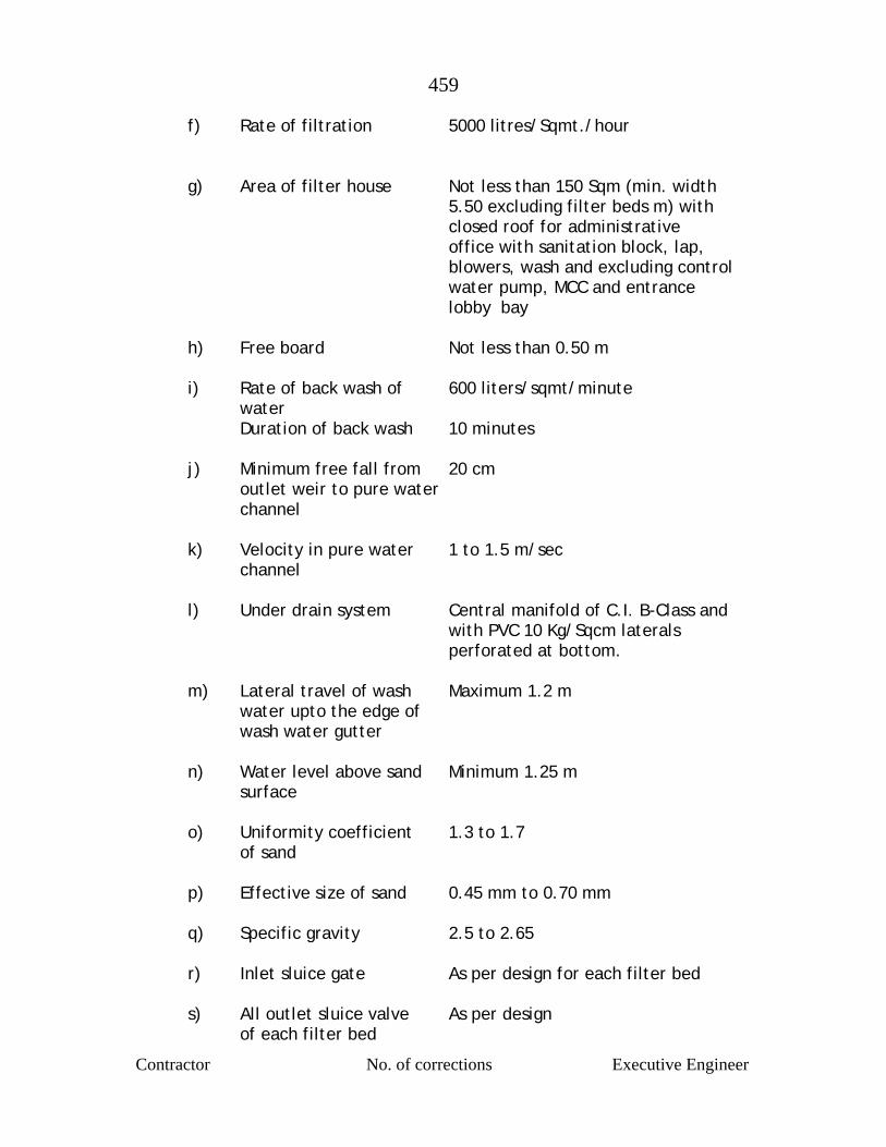
459
Contractor No. of corrections Executive Engineer
f) Rate of filtration 5000 litres/Sqmt./hour g) Area of filter house Not less than 150 Sqm (min. width 5.50 excluding filter beds m) with closed roof for administrative office with sanitation block, lap, blowers, wash and excluding control water pump, MCC and entrance lobby bay h) Free board Not less than 0.50 m i) Rate of back wash of 600 liters/sqmt/minute water Duration of back wash 10 minutes j) Minimum free fall from 20 cm outlet weir to pure water channel k) Velocity in pure water 1 to 1.5 m/sec channel l) Under drain system Central manifold of C.I. B-Class and with PVC 10 Kg/Sqcm laterals perforated at bottom. m) Lateral travel of wash Maximum 1.2 m water upto the edge of wash water gutter n) Water level above sand Minimum 1.25 m surface o) Uniformity coefficient 1.3 to 1.7 of sand p) Effective size of sand 0.45 mm to 0.70 mm q) Specific gravity 2.5 to 2.65
r) Inlet sluice gate As per design for each filter bed
s) All outlet sluice valve As per design of each filter bed
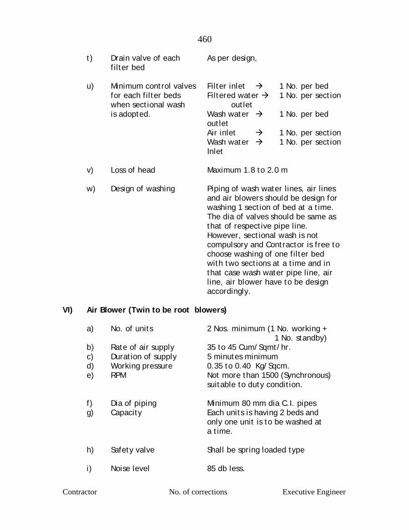
460
Contractor No. of corrections Executive Engineer
t) Drain valve of each As per design, filter bed u) Minimum control valves Filter inlet 1 No. per bed for each filter beds Filtered water 1 No. per section when sectional wash outlet is adopted. Wash water 1 No. per bed outlet Air inlet 1 No. per section Wash water 1 No. per section Inlet v) Loss of head Maximum 1.8 to 2.0 m w) Design of washing Piping of wash water lines, air lines and air blowers should be design for washing 1 section of bed at a time. The dia of valves should be same as that of respective pipe line. However, sectional wash is not compulsory and Contractor is free to choose washing of one filter bed with two sections at a time and in that case wash water pipe line, air line, air blower have to be design accordingly. VI) Air Blower (Twin to be root blowers) a) No. of units 2 Nos. minimum (1 No. working + 1 No. standby) b) Rate of air supply 35 to 45 Cum/Sqmt/hr. c) Duration of supply 5 minutes minimum d) Working pressure 0.35 to 0.40 Kg/Sqcm. e) RPM Not more than 1500 (Synchronous)
suitable to duty condition.
f) Dia of piping Minimum 80 mm dia C.I. pipes g) Capacity Each units is having 2 beds and only one unit is to be washed at a time. h) Safety valve Shall be spring loaded type i) Noise level 85 db less.
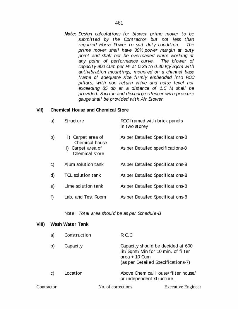
461
Contractor No. of corrections Executive Engineer
Note: Design calculations for blower prime mover to be submitted by the Contractor but not less than required Horse Power to suit duty condition.. The prime mover shall have 30% power margin at duty point and shall not be overloaded while working at any point of performance curve. The blower of capacity 900 Cum per Hr at 0.35 to 0.40 Kg/Sqcm with antivibration mountings, mounted on a channel base frame of adequate size firmly embedded into RCC pillars, with non return valve and noise level not exceeding 85 db at a distance of 1.5 M shall be provided. Suction and discharge silencer with pressure gauge shall be provided with Air Blower
VII) Chemical House and Chemical Store a) Structure RCC framed with brick panels in two storey b) i) Carpet area of As per Detailed Specifications-8 Chemical house ii) Carpet area of As per Detailed specifications-8 Chemical store c) Alum solution tank As per Detailed Specifications-8 d) TCL solution tank As per Detailed Specifications-8 e) Lime solution tank As per Detailed Specifications-8 f) Lab. and Test Room As per Detailed Specifications-8 Note: Total area should be as per Schedule-B VIII) Wash Water Tank a) Construction R.C.C. b) Capacity Capacity should be decided at 600 lit/Sqmt/Min for 10 min. of filter area + 10 Cum (as per Detailed Specifications-7)
c) Location Above Chemical House/filter house/ or independent structure.
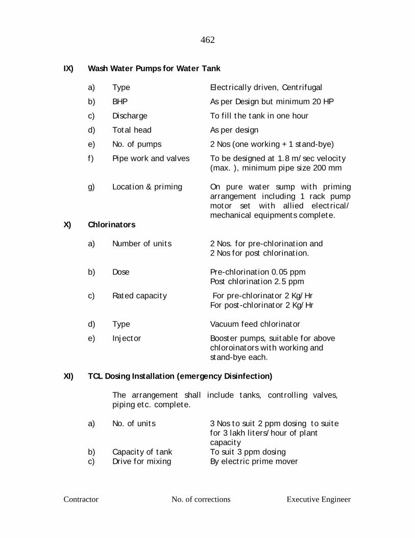
462
Contractor No. of corrections Executive Engineer
IX) Wash Water Pumps for Water Tank a) Type Electrically driven, Centrifugal
b) BHP As per Design but minimum 20 HP
c) Discharge To fill the tank in one hour
d) Total head As per design
e) No. of pumps 2 Nos (one working + 1 stand-bye)
f) Pipe work and valves To be designed at 1.8 m/sec velocity (max. ), minimum pipe size 200 mm g) Location & priming On pure water sump with priming
arrangement including 1 rack pump motor set with allied electrical/ mechanical equipments complete.
X) Chlorinators a) Number of units 2 Nos. for pre-chlorination and 2 Nos for post chlorination. b) Dose Pre-chlorination 0.05 ppm Post chlorination 2.5 ppm
c) Rated capacity For pre-chlorinator 2 Kg/Hr For post-chlorinator 2 Kg/Hr d) Type Vacuum feed chlorinator
e) Injector Booster pumps, suitable for above chloroinators with working and stand-bye each.
XI) TCL Dosing Installation (emergency Disinfection) The arrangement shall include tanks, controlling valves,
piping etc. complete. a) No. of units 3 Nos to suit 2 ppm dosing to suite for 3 lakh liters/hour of plant capacity b) Capacity of tank To suit 3 ppm dosing c) Drive for mixing By electric prime mover
463
Contractor No. of corrections Executive Engineer
XII) By-passing Arrangements
As per Schedule-B and as per detailed specification (DS-6) XIII) Drainage arrangements
As per Schedule-B and as per detailed specification (DS-17) XIV) Electrical Installations
As per detailed specification given in - ES XV) Laboratory Equipment As per Detailed specification (DS-13) XVI) A) Sanitary Blocks
As per Detailed Specification (DS-18) B) Office Block As per Detailed specification (DS-20) C) Entrance Porch with RCC roof slab (3 m x 3 m size) As per Detailed specification (DS-20)
Pure Water Pump House
A) 1) Capacity 1 Hour 2) Type RCC
B) CCT required CCT shall be provided for adequate contact of Chlorine & water
XVII) Pure Water Sump
a) Floor area Minimum 10 to 20 Sqm. per pump set b) Location By the side of pump/on sump c) Height 6 m (minimum) XVIII) Internal Roads
As per Detailed specification (DS-14) XIX) The design and layout of mechanical equipments and electrical
installations required for flash mixer, gear box motor, clarifier
464
Contractor No. of corrections Executive Engineer
bridge and motor, gear box, wash water pumps, air blowers,
chlorinators, alum mixing pumps shall be got approved by Executive
Engineer (Mech.).
XX) The design, drawings and layouts shall be submitted to Executive
Engineer for approval prior to execution of work.
XXI) All the flooring in water treatment plant shall be provided with
vitrified tiles. The flooring of chemical house and store shall have
25 to 40 mm thick polished Kota/ flooring. And the stair case and
all the steps shall have 25 to 40 mm thick polished Kota stone. All
the skirting shall be with vitrified tiles in all inside faces of the
walls of the building, except alum store. All the windows shall
have marble stone framing.
XXII) All exterior doors, windows, ventilators shall be provided with RCC
lintels and chajjas in a box type or any other suitable architectural
form. Entrance shall have at least 3.00 m porch in RCC with
architectural view.
XXIII) Water proof cement painting and distempering.
a) All the internal plastered and finished faces of all the walls,
columns etc. shall be given three coats of oil bound
distemper of approved quality and shade. The ceiling shall
be given two coats of water proof cement paint.
b) All external plastered and finished faces of walls in RCC
masonry, columns etc. shall be given tree coats of water
proof cement paint of approved shade. The finish of exterior
faces shall give aesthetic appearance to the building.
c) The colour scheme shall got approved from the Executive
Engineer in-Charge.
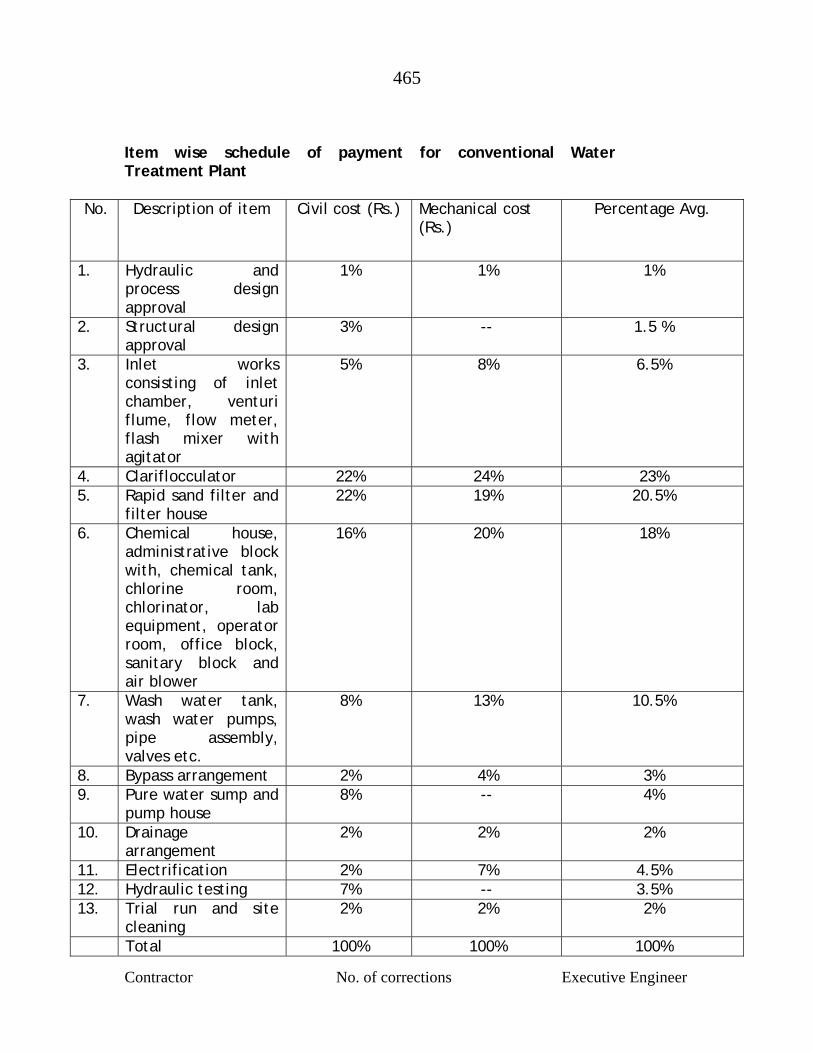
465
Contractor No. of corrections Executive Engineer
Item wise schedule of payment for conventional Water Treatment Plant
No. Description of item Civil cost (Rs.) Mechanical cost (Rs.)
Percentage Avg.
1. Hydraulic and process design approval
1% 1% 1%
2. Structural design approval
3% -- 1.5 %
3. Inlet works consisting of inlet chamber, venturi flume, flow meter, flash mixer with agitator
5% 8% 6.5%
4. Clariflocculator 22% 24% 23% 5. Rapid sand filter and
filter house 22% 19% 20.5%
6. Chemical house, administrative block with, chemical tank, chlorine room, chlorinator, lab equipment, operator room, office block, sanitary block and air blower
16% 20% 18%
7. Wash water tank, wash water pumps, pipe assembly, valves etc.
8% 13% 10.5%
8. Bypass arrangement 2% 4% 3% 9. Pure water sump and
pump house 8% -- 4%
10. Drainage arrangement
2% 2% 2%
11. Electrification 2% 7% 4.5% 12. Hydraulic testing 7% -- 3.5% 13. Trial run and site
cleaning 2% 2% 2%
Total 100% 100% 100%
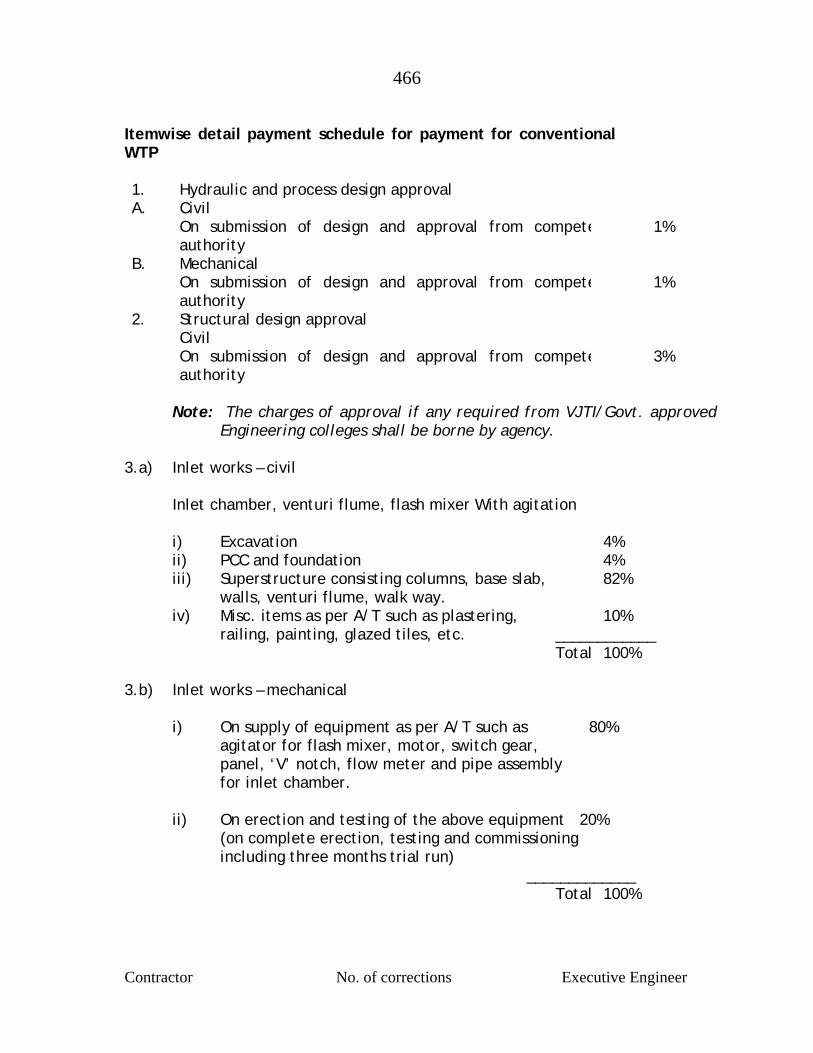
466
Contractor No. of corrections Executive Engineer
Itemwise detail payment schedule for payment for conventional WTP 1. Hydraulic and process design approval A. Civil On submission of design and approval from compete
authority 1%
B. Mechanical On submission of design and approval from compete
authority 1%
2. Structural design approval Civil On submission of design and approval from compete
authority 3%
Note: The charges of approval if any required from VJTI/Govt. approved
Engineering colleges shall be borne by agency. 3.a) Inlet works – civil Inlet chamber, venturi flume, flash mixer With agitation i) Excavation 4% ii) PCC and foundation 4% iii) Superstructure consisting columns, base slab, 82% walls, venturi flume, walk way. iv) Misc. items as per A/T such as plastering, 10% railing, painting, glazed tiles, etc. ____________ Total 100% 3.b) Inlet works – mechanical i) On supply of equipment as per A/T such as 80% agitator for flash mixer, motor, switch gear, panel, ‘V’ notch, flow meter and pipe assembly for inlet chamber. ii) On erection and testing of the above equipment 20% (on complete erection, testing and commissioning including three months trial run) _____________ Total 100%
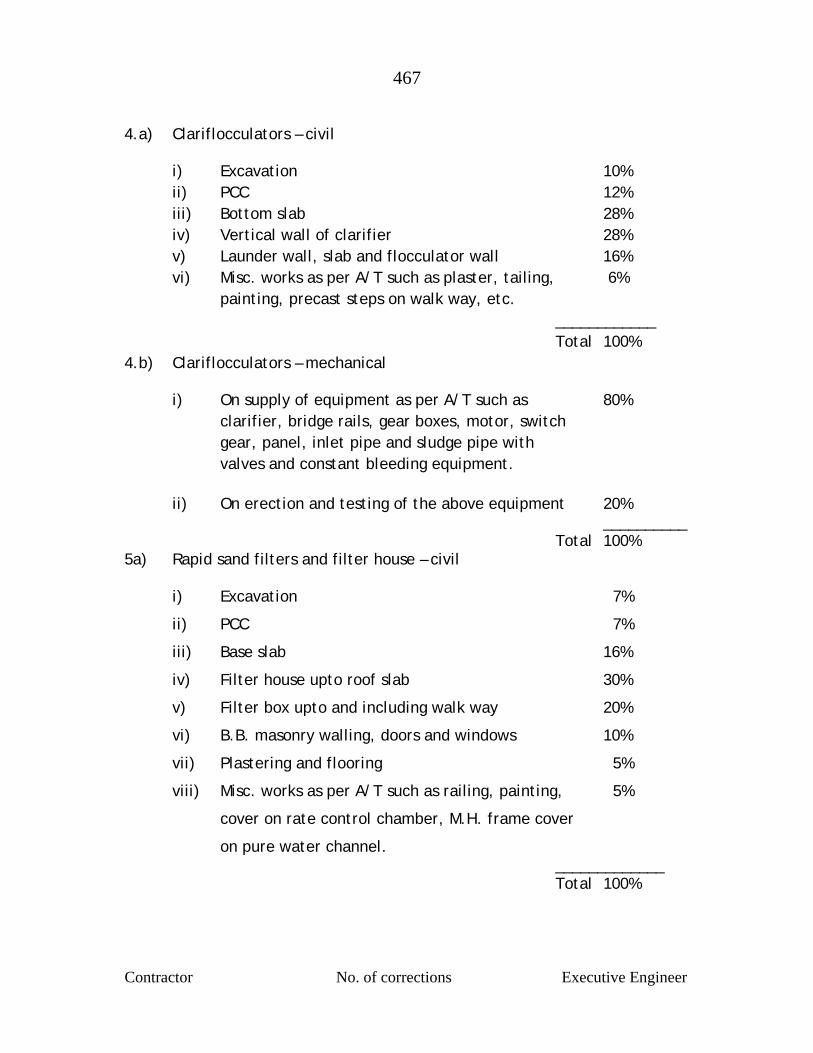
467
Contractor No. of corrections Executive Engineer
4.a) Clariflocculators – civil i) Excavation 10% ii) PCC 12% iii) Bottom slab 28% iv) Vertical wall of clarifier 28% v) Launder wall, slab and flocculator wall 16% vi) Misc. works as per A/T such as plaster, tailing, 6% painting, precast steps on walk way, etc. ____________ Total 100% 4.b) Clariflocculators – mechanical i) On supply of equipment as per A/T such as 80% clarifier, bridge rails, gear boxes, motor, switch gear, panel, inlet pipe and sludge pipe with valves and constant bleeding equipment. ii) On erection and testing of the above equipment 20% __________ Total 100% 5a) Rapid sand filters and filter house – civil i) Excavation 7%
ii) PCC 7%
iii) Base slab 16%
iv) Filter house upto roof slab 30%
v) Filter box upto and including walk way 20%
vi) B.B. masonry walling, doors and windows 10%
vii) Plastering and flooring 5%
viii) Misc. works as per A/T such as railing, painting, 5%
cover on rate control chamber, M.H. frame cover
on pure water channel. _____________ Total 100%
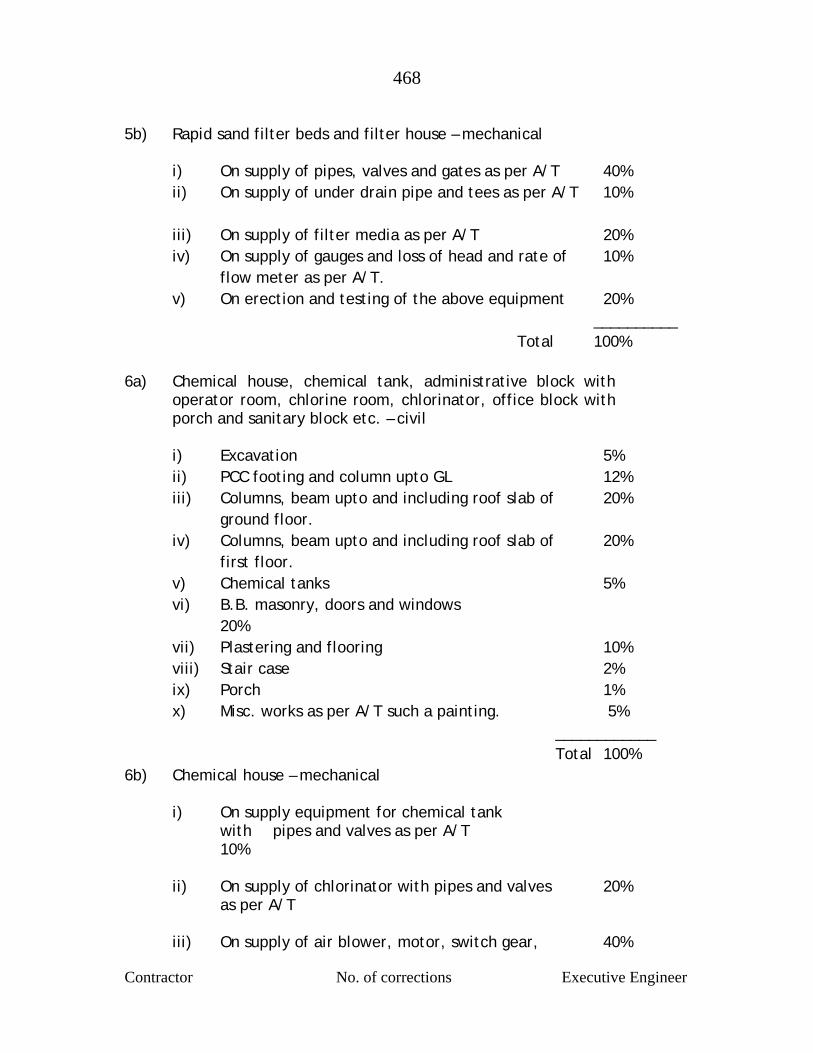
468
Contractor No. of corrections Executive Engineer
5b) Rapid sand filter beds and filter house – mechanical
i) On supply of pipes, valves and gates as per A/T 40% ii) On supply of under drain pipe and tees as per A/T 10% iii) On supply of filter media as per A/T 20% iv) On supply of gauges and loss of head and rate of 10% flow meter as per A/T. v) On erection and testing of the above equipment 20% __________ Total 100%
6a) Chemical house, chemical tank, administrative block with operator room, chlorine room, chlorinator, office block with porch and sanitary block etc. – civil
i) Excavation 5% ii) PCC footing and column upto GL 12% iii) Columns, beam upto and including roof slab of 20% ground floor. iv) Columns, beam upto and including roof slab of 20% first floor. v) Chemical tanks 5% vi) B.B. masonry, doors and windows
20% vii) Plastering and flooring 10% viii) Stair case 2% ix) Porch 1% x) Misc. works as per A/T such a painting. 5% ____________ Total 100% 6b) Chemical house – mechanical i) On supply equipment for chemical tank
with pipes and valves as per A/T 10%
ii) On supply of chlorinator with pipes and valves 20% as per A/T iii) On supply of air blower, motor, switch gear, 40%
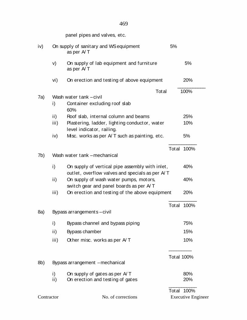
469
Contractor No. of corrections Executive Engineer
panel pipes and valves, etc. iv) On supply of sanitary and WS equipment 5% as per A/T v) On supply of lab equipment and furniture 5% as per A/T vi) On erection and testing of above equipment 20% ___________
Total 100% 7a) Wash water tank – civil i) Container excluding roof slab
60% ii) Roof slab, internal column and beams 25% iii) Plastering, ladder, lighting conductor, water 10% level indicator, railing. iv) Misc. works as per A/T such as painting, etc. 5% ___________ Total 100% 7b) Wash water tank – mechanical i) On supply of vertical pipe assembly with inlet, 40% outlet, overflow valves and specials as per A/T ii) On supply of wash water pumps, motors, 40% switch gear and panel boards as per A/T iii) On erection and testing of the above equipment 20% ___________ Total 100% 8a) Bypass arrangements – civil i) Bypass channel and bypass piping 75%
ii) Bypass chamber 15%
iii) Other misc. works as per A/T 10%
_________
Total 100% 8b) Bypass arrangement – mechanical i) On supply of gates as per A/T 80% ii) On erection and testing of gates 20% ___________ Total 100%
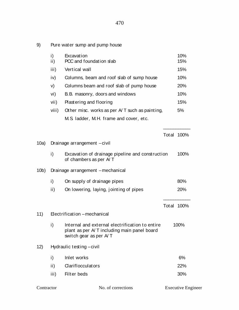
470
Contractor No. of corrections Executive Engineer
9) Pure water sump and pump house
i) Excavation 10% ii) PCC and foundation slab 15%
iii) Vertical wall 15%
iv) Columns, beam and roof slab of sump house 10%
v) Columns beam and roof slab of pump house 20%
vi) B.B. masonry, doors and windows 10%
vii) Plastering and flooring 15%
viii) Other misc. works as per A/T such as painting, 5%
M.S. ladder, M.H. frame and cover, etc.
___________
Total 100%
10a) Drainage arrangement – civil i) Excavation of drainage pipeline and construction 100% of chambers as per A/T 10b) Drainage arrangement – mechanical i) On supply of drainage pipes 80%
ii) On lowering, laying, jointing of pipes 20%
___________
Total 100%
11) Electrification – mechanical
i) Internal and external electrification to entire 100% plant as per A/T including main panel board switch gear as per A/T
12) Hydraulic testing – civil
i) Inlet works 6%
ii) Clariflocculators 22%
iii) Filter beds 30%
471
Contractor No. of corrections Executive Engineer
iv) Wash tanker tank 12%
v) Bypass channel 5%
vi) Sump 20%
vii) Drainage arrangement 5%
Total 100% 13) Trial run and site cleaning
Civil 2% Mech. 2% NOTE: As separate provision is made for hydraulic testing and testing of mechanical equipment in the break up schedule no further deduction through R.A. Bills on account of hydraulic testing is necessary. Daily record of raw water pumped, pure water pumped from WTP, water pumped to ESR, Alum doses, Alum consumed, turbidity, pH, chloride dose, residual chlorine at consumer end etc. shall be maintained. Calibration chart for turbidity and chlorine dose shall be prepared. Daily record of filters washed

472
Contractor No. of corrections Executive Engineer
DETAILED ITEMWISE SPECIFICATIONS General These specifications as laid down hereinafter are in amplification of the
requirement already specified in preceding of this tender and further fully
complementary to it. The elaborate specifications for electrical works are
given separately in addition to the following. Additional specification for
mechanical work and civil work are separately given.
DS-1 ITEM NO. 1 AERATION FOUNTAIN (RCC) Accessories 1.2 m wide walkway and 25 mm dia double row G.I. pipe railing at
the outer periphery of aeration fountain. It is necessary to provide
RCC stair for inlet chamber. Ceramic tiles in white cement shall be
provided to cascade and collecting launder.
Mechanical Equipment The central inlet to the chamber shall be of CI pipe of required
thickness and dia with bell mouth at its top, increased to suitable
diameter covered with dome shaped MS cage. From the duck foot
bend, M.S. pipe line extending upto 15.00 m distance measured from
center to duck foot bend shall be provided by the Contractor with
required specials as per site conditions.
DS-2 Measuring Flume, Flow Measuring Equipment etc.. a) Design The flume shall be designed as an open channel type for
required flow with free board or not less than 30 cm. The
measuring flume shall have a baffle wall or appropriate
arrangement for recirculation jambs and side chamber for
473
Contractor No. of corrections Executive Engineer
float. The item shall include construction of entire length of
channel starting from the inlet chamber to the receiving point
at flash mixer. Ref. ISS:6059 and IS:9117 of latest edition shall
be followed.
b) Accessories On one side walkway of 1.20 m width with 25 mm dia G.I. pipe
railing in double row at the outer edge and as per
specifications for mechanical engineering works shall be
provided.
c) Mechanical Equipment Simple flow meter with dial type indicator shall be provided
and installed near the flume. The measuring device shall have
a capacity of measuring minimum flow of 100 cum/hour and
maximum flow of 500 cum/hour correct upto a rate of 5
cum/hour as per ISS:6756, 6236 and 2032 of latest edition.
In order to reduce head loss, the measuring device shall be on
Partial flume principle. It shall have, however, to be assured
that the channel does not head up due to churning of water in
the flash mixer. There should be clear over fall from channel
to further unit. The channel and inlet chamber channel shall
be provided with a drain pipe with valve for purpose of
washing. At this time, channel shall be provided with
penstock gate in M.S. to separate out from flash mixer.
DS-3 Flash Mixer a) Design and Construction A flash mixer of required capacity shall be constructed in RCC
finished with cement plaster 1:3 mix at the water face. The
474
Contractor No. of corrections Executive Engineer
unit shall be provided with RCC slab partly covering the tank
for locating the driving unit of the agitator and for approach to
the same. The maximum detention time for flash mixer shall
be 60 seconds with side water depth of maximum 3.5 m. It
should have arrangement to receive the measured and
chlorinated raw water, dose aluminum sulphate solution
immediately and violently dispensed the solution throughout
the bulk of water in a flash mixer chamber. The hydraulic
design should be such that the accuracy of the flume is not
affected by the hydraulic behaviour of the section. The design
should provide flash mixing chamber with submerged mixers,
shaft driven from overhead motors and gear box each designed
to impart turbulent energy into water at an anticipated rating
of 2.25 kW (minimum). Aluminum sulphate shall be dosed
immediately adjacent to the flash mixing device.
b) Accessories The walkway of 1.20 m width shall be provided with 25 mm dia
G.I. pipe railing in the double row as specified in general
mechanical engineering works specification attached.
c) Electrical and Mechanical Equipments This will be consists of the following i) Frame agitators with stainless steel blades and stainless
steel vertical shaft mounted on bearing of sufficient strength to prevent vibrations.
ii) Electrical motor of suitable horse power, starter and
reduction gear (not less than 3 HP) Torque rating of gear box shall be designed and submitted for approval.
iii) Suitable size outlets with proper controlling
arrangements of flow. iv) Water tight penstock on the inlet.
475
Contractor No. of corrections Executive Engineer
v) Protective covers of G.I. sheets duly painted for motor
with tray to prevent failing of lubricant into water. vi) C.I. pipe lines between flash mixer and clariflocculators
shall be provided with control valves and suitable chambers.
vii) Flash mixer draining arrangements shall be provided
with a suitable sluice valve and chamber. DS-4 Clariflocculators A) Designing The item include designing and construction of RCC radial flow
clariflocculators with central flocculation chamber of 30
minutes detention period and outer annular clarifier of 2.5
hours (minimum) detention period overflow rate not exceeding
30 Cum/Sqmt/day excluding sufficient capacity for sludge
storage shall be provided, however, capacity below SWD shall
not be considered. Peripheral launder to clariflocculators shall
be provided to take clarified water to the launder with
suitable bevel shaped weir be provided on wall. The shape,
depth and size of inlet and outlet of clariflocculators shall be
so designed that the gentle overturning motion given to the
water in the flocculating zone shall bring about complete
agglomeration of floc to the maximum possible extent so as to
achieve quick settlement in the clarifier zone with a view to
lower the turbidity below 10 ppm preferably, when there is
maximum raw water turbidity. In short (a) turbidity not more
than 10 ppm, (b) suspended solids not more than 20 mg/lit, (c)
Total Al. Not more than 0.30 mg/lit for water leaving the
clariflocculators shall be achieved, wherever pre-chlorination
unit is provided a residual chlorine of 0.2 mg/lit for water
leaving the clariflocculators shall be maintained.
476
Contractor No. of corrections Executive Engineer
b) Construction The outer clariflocculators wall shall be in RCC of thickness
not less than 18 cm. The bottom slab shall be in RCC of
minimum thickness of 15 cm. It shall have a slope of 1 in 15
from outer periphery towards the center. The flocculator wall
shall be 12 cm thick in RCC with cement plaster on both the
sides as it is not retaining any water. The central inlet to the
flocculator chamber shall be RCC shaft of adequate diameter
with suitable slot opening at the top. This includes providing,
laying, lowering and jointing C.I. pipes of suitable diameter
from flash mixer outlet to central inlet shaft of the
flocculation chamber. The portion of C.I. pipe below the floor
of the clariflocculators will be encased in CC M-300 with
adequate cover of 20 cm from all sides. The flocculator wall
shall rest on RCC ring beam and column of suitable section and
height so that water from flocculator will pass on the clarifier
readily, below the flocculator wall.
The sludge pipe from the central sludge pocket upto chamber
of nearest drainage system shall be of CI pipe of B class, S & S
type. The pipes will be encased in CC M-300 upto cover 20 cm
on all sides for length below the floor of the clariflocculators.
The diameter shall not be less than 300 mm. It should be
possible to remove the entire sludge accumulated at the
centre of the pit of the clariflocculators by gravity alone to
the last drop when it is to be emptied for repairs or so. It also
includes sluice valve of equal dia to that of pipe line with
extended spindle and wheel. A telescopic bleed device shall
be provided separately and drained in the sludge chamber.
477
Contractor No. of corrections Executive Engineer
There shall be RCC circular launder outside the edge of
vertical wall and extending over to the whole periphery
around the weir. The launder should have bevel shape RCC
weir having. The launder shall be connected at suitable points
to inlet chamber or pipe of the filter unit. The launder shall
be designed to take full flow in clariflucculator and size should
be such that minimum clear free fall 10 cm in the launder shall
be maintained. From launder of clarifier, clarified water
channel of required mld capacity will lead to filter inlet.
c) Accessories The clarifier will have 1.20 M wide peripheral walkway all
round with G.I. pipe railing 25 mm dia in two row at the
inner/outer circumference as per general specifications for
mechanical engineering works.
d) Mechanical and Electrical Equipments This includes providing and erecting standard mechanical
equipment with required electrical wiring, switches etc.
complete. In flocculation chamber, flocculator paddles made
of epoxy coated, M.S. section of suitable size and epoxy
coated M.S. flats ( 8 mm thickness) fixed to central stainless
steel shaft of suitable dia (not less than 50 mm and as per
IS:7208:1974) should be provided. The flocculator blade shall
be of epoxy coated M.S. plate. The stainless steel central
shaft shall be provided with guide bearings to the bottom
suitable for underwater use. Even in the case of Dor Oliver
type flocculator mechanism offered by the tenderer, the
paddle shall be of M.S. and guide shaft, if used, shall be in
stainless steel. The paddles area of flocculator shall be 10 to
35% of tank sectional area in the plane of shaft and the paddle
478
Contractor No. of corrections Executive Engineer
tip velocity should be 0.30 to 0.40 m/sec the distance
between the paddle tips should be of maximum one meter.
The flocculator driving mechanism shall comprise of 400/400
Volts, 3 phase, A.C. motor of suitable mechanism section HP
(minimum 2 HP) with approved make starter connected by
worm reduction gear of suitable ratio through pinion and bevel
wheel drive. Bevel shaft shall be connected to flocculator
shaft through rigid couplings. The worm reduction gears shall
be suitable for 24 hours continuos operation. The design
calculations justifying the selection of gears, material of
construction, lubrications torque requirements verses torque
suitability of gear box, etc shall be submitted for approval.
The equipment for clarifier shall consist of a lattice girder
bridge. The bridge will be of entire diametric length of
flocculator and half the diameter of clarifier and with trolley
rails resting on the clarifier wall and the central bearing or
central shaft it should not be supported by flocculator wall.
The bridge path shall consists of a 1.2 m wide walkway made
of welded and bolted R.S. sections of suitable size and fitted
with 6 mm thick chequered plates. Two Nos. of scraper arms
with scraper blades of suitable size covering the entire
diameter of the clarifier being suspended shall consist of
400/440 V A.C. motor of suitable HP (not less than 3 HP) with
starter of approve make jointed through coupling to worm.,
reduction gear transmitted by suitable drive imparting slow
motor to the driving mild steel wheel moving on rails. The
bearings shall be housed in high grade C.I housing with G.M.
bush for rigidity. Special current collector for transmission of
electric power from outside to the different units of bridge
shall be provided. The clarifier bridge mechanical equipment
should be given two coats of anticorrosive epoxy paint. The
479
Contractor No. of corrections Executive Engineer
panel shall be suitable for outdoor installation and switch fuse
units of approved make shall only be assembled. The drawing
should be got approved prior to fabrication and brought to the
site only after inspection by the Engineer-in-Charge.
Minimum performance
Effluent turbidity not greater than 10 ppm
S.S. not greater than 10 mg/lit
Total Al. Not greater than 0.5 mg/lit.
Outlet turbidity - 2 NTU DS-5 Filter House and Rapid Gravity Constant Rate Sand Filters a) Design The filter beds shall be located in filter house with roof slab
along with control bay in a filter house. The location of filter
house shall not be on pure water sump. There shall be
minimum 2 Nos. of filter beds which can be operated
independently. The ratio of length and breadth of each filter
bed (t here are two beds in each unit) shall not more than
1.66. Together they will deal with a required flow capable of
filtering at the rate of 5000 litres/Sqmt/hour. The system
shall be designed such that it should be possible to overload
the filters by 20% without affecting the quality of filtered
water.
It is proposed to backwash the filter with air wash at the rate
of 35 to 45 Cum/Sqmt/hr of filter bed after 0.35 Kg/Sqcm
pressure at the under drains and followed by wash water at
the rate of 600 lit/Sqmt/minute of the filter bed area for a
duration of 10 min.. It shall be ensured that the lip level of
wash water trough is kept minimum 60 cm above the surface
of sand to accommodate expansion of sand bed.
480
Contractor No. of corrections Executive Engineer
i) 1.20 m wide walkway all round the filter beds with double row of G.I. pipe railing of 25 mm dia as specified in the general specifications for mechanical engineering works.
ii) Space for housing air blowers and panel board in a separate
filter annex room with adequate working space. iii) An office room. iv) Pressure reducing arrangement to reduce pressure of water
supplied from wash water tank for back washing the filter beds if necessary.
v) Each unit shall be complete in all respect with inlet valves,
wash water inlet valve, wash water outlet valves etc.. Velocities permissible in different conduits and valves of filter house shall be as below.
a) At inlet to filter 1.00 m/sec. b) At inlet to wash water 2.40 to 3.0 m/sec c) At outlet of wash water 2.0 m/sec d) At outlet of filtered water 1.0 m/sec e) Air inlet 25 m/sec. b) Filter Media This shall consist of properly washed quartz sand of effective
size between 0.45 mm to 0.70 mm with a uniformity
coefficient between 1.3 to 1.7. The gravel media shall be as
per standard specifications of rapid gravity filters. The filter
bed shall consist of 0.60 to 0.70 m of sand supported on 0.45
m gravel. The filter sand shall be granular, hard, durable,
well-washed and screened. It shall be free from clay, dust,
shale, loam, organic impurities, vegetation and other
impurities and shall not contain more than 10% micaceous
matter. The sand crushed and powdered and immersed in
concentrated hydrochloric acid shall not loose more than 1.5%
of weight calculated as CaCO3 and not more 2% weight shall be
lost in case of sand crushed/powdered after burning. The
481
Contractor No. of corrections Executive Engineer
frailty weight cost after milling for 15 minutes (750 strokes)
shall be less than 10% and for 30 minutes (1500 strokes) shall
be less than 20%. The gravel shall be hard, durable and shall
not disintegrate under the action of water. The smallest and
largest size shall be 3 mm and 50 mm respectively. The
Contractor shall specify the size and thickness of each layer of
filter media (gravel and sand. The filter media shall be so
selected to achieve filtration rate or 6000 liter/Sqmt/hour
and turbidity not 1 NTU or less
c) Construction The filter house and filter annex building shall be of RCC
framed structure. Filter house will comprise of closed control
bay and filter beds. Ground floor filter annex shall be double
storeyed comprising of inter-annex hall with porch at main
control door, air blower room, panel board installation,
general administrative block, 1.00 m wide staircase from
annex room to operating floor of filter house shall be
provided.
Two Nos. RCC stair case 1.0 m wide shall be provided for going
from filter operating platform to inspection gallery. These
staircases shall be provided with G.I. pipe hand railing as per
specifications mentioned for mechanical engineering work.
The steps of staircase shall be provided with CC chequered
tiles.
Dimensions of the brick walls, external and internal, should be
appropriate for the function of wall to serve and shall not be
less than 23 cm. For brick masonry there shall be sponge
finished cement plaster in CM 1:3 mix from outside and inside
482
Contractor No. of corrections Executive Engineer
face of the wall shall be plastered in CM 1:3 mix and smooth
finished with neeru. The thickness of plaster shall be 12 mm
for brick masonry.
The inside face of inspection chamber and filter water outlet
channel connecting portion shall be provided with 6 mm thick
first class quality white glazed tiles, with ceramic glazed
corner etc. set in white cement. Simple flow meter with dial
type indicator shall be provided to measure rate of filtration
of each filter. Also rectangular notch shall be provided in the
inspection chamber made of stainless steel. The chamber
shall be provided with suitable bulkhead fittings for
illumination. Inspection chambers shall be provided with
aluminum angles framed both side with protected transparent
cover. The inspection box and filtered water outlet channel
shall be in RCC. The cover of channel shall be in RCC slab
finished with marble mosaic tiles, of approved colour, shade
and size. There should be four openings of 90 x 60 cm for
getting into the channel and these will be fitted with 90 x 60
cm heavy duty C.I. manhole frame and cover, the width of the
passage (walkway) around and in between t he two adjacent
filter beds shall be 1.20 m minimum. Walkway around and
filters units shall be provided with 25 mm dia double row G.I.
pipe and railing as specified in the general specifications for
mechanical engineering works. Railing shall also be provided
along the pipe gallery. The clear height shall 4 m minimum
above filter operating platform level to roof slab bottom. The
roof and the ceiling etc. shall e finished as specified in the
general specifications for civil engineering works. The
minimum difference in the operating floor and the walkway
483
Contractor No. of corrections Executive Engineer
level on top of P.W. channel shall be 2.7 m to be decided as
per hydraulics.
The position of inspection box, RCC staircase, location of air
blower etc. should be so chosen as to offer very neat and tidy
appearance to the filter house.
The ground floor of the filter annex should accommodate air
blowers, entrance hall with entrance counter, ten chairs etc.
A decorative partly glazed and partly paneled large size door
should be provided.
d) Mechanical Equipments i) Piping Under this arrangement inlet piping, with regulating
arrangement of approved type, outlet pipe with central
valves, filter back wash piping waste water discharging
piping with valves and air pipe from the blower upto the
under-drainage system with suitable control valves and
air releases with necessary piping, extended spindle
penstock and operating C.I. hand wheel, etc. as
required shall be provided. All valves should be capable
of being operated from operating floor. All the valves
used shall be of Kirloskar/IVC/IVI make only.
All pipes shall be of CI B-class pipes with flanged joint
upto 300 mm dia. Above 300 mm dia M.S. flanged pipes
of minimum 6 mm thickness may be provided. This also
includes the required number of specials to negotiate
bends and inter connections, etc. The complete piping
484
Contractor No. of corrections Executive Engineer
for backwash of water shall be provided suitable to
wash two filter bed at a time.
ii) Under drainage system This shall be provided with Central manifold of C.I B-
Class pipe with plain ended C.I. tees to be laid over RCC
flooring and laterals of PVC 6 Kg.Sqcm with perforations
at bottom. The under drainage system shall be
designed for the washing rate which shall not exceed
600 lit/Sqmt/min. The under drainage system shall
consists of manifolds and laterals as per design of the
Contractor to satisfy the obligatory requirement.
The ratio of the area of the manifold to the total area
of laterals drawing into the manifold shall be 1.5 to 2.
Wash water gutter (laterals and main) shall be properly
designed so that while functioning, it facilitates
complete bed washing. There is no loss in filter
material. Wash water travel shall not exceed 1.20 m
transversely. Height of lip of the gutter shall be
designed taking into consideration the bed expansion
during backwash. Duration of wash should not exceed
10 minutes in any case. The quantity of back wash
water used shall not exceed on an average 2% of total
quantity of filtered water as counted on the average of
year's working. The piping shall be sufficiently fixed to
RCC floor to prevent its getting detached from the
floor. The under drain system shall be capable of taking
an overload of 20%.
485
Contractor No. of corrections Executive Engineer
The under drain system should be capable of taking an
overload of 20% as stipulated above. So also the filter
outlet control system should also be capable of taking
an occasional overload of 20% of the rated capacity
hydraulically.
iii) Complete system of waste water draw off for collecting
and disposing off waste water during cleaning of filter
beds shall be provided as to above requirements.
iv) Flow Control System for Constant Rate Filtration with
Influent Flow System The filter shall work on constant rate filtration by
influent flow splitting. In the case of influent flow
splitting, the entire flow of influent (clarified water
conveyed to filters) shall be split equally at the inlet of
each filter unit of 2 beds by means of simple weirs. The
rectangular weirs with equal dimensions are located at
the same elevation in the concrete weir boxes. The
location of weir should be such that it should be
possible to measure head on the weir and regulate the
discharge by providing isolation gate for every weir.
The spindle of this gate should not reduce the walkway
width. The influent channel shall be connected to the
inlet of weir boxes by means of isolating gates. Filter
boxes should have to be designed in such a way that the
depth of standing water on the bed should be about 3.5
to 4 m supported by due design. The influent channel
should be designed for the velocity of 0.6m/sec. To
measure the loss of head , indicator shall be suitably
provided.

486
Contractor No. of corrections Executive Engineer
The sizing of the box and that of inlet port should be
large enough so that they do not cause any turbulence
over the weir. The design and arrangement of constant
rate filtration process shall be as directed by the
Engineer-in-Charge and as specified in Para 7.6.8.1. of
CPHEEO manual.
v) General Layout and Carpet Area Full details should be indicated in general layout plan. DS-6 Bypass Arrangement a) Design and Construction
Bypass arrangement shall be provided as per detail mentioned
in Schedule-B. The arrangement shall be designed for a
required flow plus 20% overload. It shall also include
construction of RCC chamber of suitable size wherever
necessary.
It should be possible to bypass. i) Flash mixer and clariflocculators.
ii) Filters totally and/or partially
iii) Flash mixer and clariflocculators and filters
iv) Clariflocculators shall be designed to take water to the chlorination point of pure water channel in the filter house proper.
The period of bypass will be minimum possible required for
various units and repairs, whether panel or otherwise. During
this period the hydraulic capability of various units will be
utilized to the maximum but in any case no unit shall be
overflooded nor the quality of pure water be deteriorated
487
Contractor No. of corrections Executive Engineer
beyond acceptable limits. The Contractor shall give trial of
such hydraulic bypass and limits of end quality achieved.
i) Piping Pipes and specials shall be of C.I. LA Class. ii) CID/F sluice valves, sluice gates, penstocks, etc. at
suitable point shall be provided with operating guide-rod and wheel etc. The C.I. sluice gates, penstocks, etc. should be reputed make and must have ISI certification mark and should conform to the relevant latest ISI sluice valve shall be used exclusively when the difference of water pressure on both sides exceed 1.0 m
DS-7 Wash Water Tank a) Design and Construction The tank shall be of RCC with required capacity. The capacity
of wash water tank should be sufficient for cleaning one filter
bed with two sections even though only one section is to be
washed at a time at the rate of 600 lit/sqmt/min. for 10
minutes duration and shall be provided at a suitable location.
In case total beds are more than 4, then capacity should be
sufficient for washing 2 beds instead of 1 bed. The tank shall
be at such an elevation as would give an effective net head of
8 to 10 m at the underdrain of the filter beds. In addition to
above 10 cum extra capacity be provided for other utility.
b) Allied Items i) Water level indicator One water level indicator shall be installed in the filter
house ii) RCC spiral staircases for access to the top of the tank
and Aluminium ladder inside the tank. iii) 2 Nos of C.I. heavy-duty manhole covers with frames of
size 0.9 x 0.6 m with locking arrangements.
488
Contractor No. of corrections Executive Engineer
iv) Lightening conductor One No. as per relevant IS specifications. v) Piping and Valves C.I. pipe line with specials, valves etc. shall be provided
from wash water tank filling pump in pump house to wash water tank and wash water tank to filter for back wash and the required sizes of G.I. pipes for chemical tank and sanitary block shall be provided from wash water tank.
DS-8 Chemical House and Store Chemical Feeding Equipment a) Design The building shall be constructed in two floors as indicated. It
shall be a RCC framed structure in columns and beams with
brick paneling of minimum 23 cm thickness. It should not be
located on pure water sump.
b) Area and Location The chemical house shall be so located that the chemical
could be conveniently and easily fed and controlled between
the inlet chamber and flash mixer and fed by gravity. The
minimum carpet area for chemical house (in two stories) and
chemical store in single or two story shall be as below.
Chemical House Chemical store total minimum
75 Sqmt. 10Sqmt min. separately required Above area is the total area, which can be split in two floors.
Above areas excludes 150 sqmt. area of filter house as shown at OR-10 (V-g)
Minimum ceiling/roof height 4 m on ground floor 4.5 m on first floor
489
Contractor No. of corrections Executive Engineer
The entire construction shall be a RCC structure in columns
and beams as specified with panel of 23 cm thick brick walls
for external walling subjected for exposure to rains.
Weighting machine for alum weighing having capacity not less than 500 Kg shall be provided under this item.
c) Construction i) Ground floor The ground floor shall accommodate alum store for 90 days
lime for 30 days and TCL powder for 7 days requirement and
other misc. store. Platform type alum weighing machine of
1.00 MT capacity, the average height 7of the plinth of
chemical house shall be 0.6 m
ii) First floor The first floor shall accommodate minimum 3 RCC solution
tanks. Similarly it shall also accommodate laboratory, test
room and TCL solution tanks for pre-chlorination and post-
chlorination and lime tank. The chemical tanks shall be
designed and provided as below.
a) Alum Tank. Minimum three tanks (one for preparation, second for
dosing and third for stand by) each tank capable of
giving un-interrupted dose of 2.5 ppm for 8 hours
capacity, minimum free board 0.30 m trays for
dissolving, level indicator, mechanical agitation
devices, solution feed and drain lines, solution feed
device. The inner surface of tank and dissolving tray
shall be coated with SBR. The strength of solution shall
be upto 10% only conforming to IS:9222 part-I-1979.
b) Lime solution tank

490
Contractor No. of corrections Executive Engineer
Minimum three number so lime solution tank each of 8
hours capacity to dose upto 2.5 ppm at 10% solution
strength to deal with the design flow. The inner surface
of tank and dissolving tray shall be coated with SBR.
c) TCL Tank for Post-chlorination Minimum 3 Nos. each of capacity not less than 3 hours
(1 Kg of RCL in 40 lit of water) for a dose of 3 ppm of
chlorine to deal with the design flow The inner surface
of tank and dissolving tray shall be coated with SBR.
d) TCL tanks for Pre-chlorination These shall be as per post-chlorination requirement
e) Mechanical and Other Equipment A dissolving tray of RCC trough with holes or slots shall
be provided on each tank for placing the alum cakes.
The alum solution tank shall be fed with pure water by
means of PVC 6 Kg.Sqcm. piping and valves of adequate
size from wash water tank. Each solution tank shall be
provided with brass gauge plate level indicator. The
top of the solution tank shall be covered with 50 mm
thick wooden planks properly fixed with rounded edge
and painted in three coats of oil paint. The alum mixing
paddles shall be of stainless steel of enough section and
size. Individual drive arrangement shall be provided.
Necessary wash out arrangements shall be provided. An
RCC operating platform at suitable level and of 1.20 m
width and length covering all the tanks shall be
provided. All the tanks shall have independent outlets,
491
Contractor No. of corrections Executive Engineer
feeding the dosing tank. In addition there shall also be
adequate capacity lime solution and TCL solution tank
with allied equipment to work in emergency situation.
For lime solution tank mixing paddle shall be of mild
steel with individual driving arrangement. Constant
head device with manual dose adjustment arrangement
shall be provided for all chemical solution tanks i.e.
without arrangement of automatic dose arrangement.
100% stand bye shall be given i.e. one more constant
head device at every tank be provided in spare.
All valves, pipes and fittings for dosing and washout
shall be non-corrodible materials and should be of
adequate size. Monorail operated chain pulley block of
1.0 MT capacity with geared trolley shall be provided
for handling the chemical in storage area. This can be
manually operated. In addition to the above one MT
capacity simple chain pulley block fixed to a hook of
first floor shall be provided to lift the chemicals to top
from chemical store. The chain pulley block should be
of Morris/Elephanta make
An opening of suitable size floor for lifting alum bags
from ground floor to first floor shall be provided. The
opening of the floor shall be provided with 25 mm dia
G.I pipe railing in double row and 0.85 m high. The
operating platform of solution tank shall be provided
with G.I. pipe railing. The tank shall be provided with
1.20 m wide access staircase with 15 cm wide M.S. plate
stringers of 10 posts and two rows of 25 mm dia
(internal) G.I. pipe (medium duty) on both sides.

492
Contractor No. of corrections Executive Engineer
Precaution shall be taken to ensure continuity of
feeding, alum solution by gravity and prevention of gas
hazards, corrosion. Accuracy of the dosing equipment
shall be an essential requirement. Constant head
device with manual closing arrangement shall be
provided.
The chemical house, platform, staircase shall have flooring of corrosion proof tiles.
DS-9 Wash Water Pump Sets a) Design and Specifications Two Nos. of wash water pump sets as described under the
statement of obligatory requirement shall be provided. One
will work and another pump sets as standby. Hence, total 2
Nos. of pumps shall be provided with 100% standby for wash
water pumping and capacity to fill up the wash water tank in 1
hours. The pump characteristics shall be suitable for
satisfactory operation for head range qualified. The pump
speed shall not exceed 1500 rpm (Syn.). The efficiency shall
not be less than 75% at duty point.
Construction Features The pumps shall be single stage horizontal split casing
centrifugal pump. A priming funnel and cock shall also be
provided. But the pump shall run without cavitation. The
impeller shall be balanced both statically and dynamically.
The interior surface and passages shall be smooth finished.
The shaft shall be of solid type and manufactured from high
tensile steel. The shaft sleeves shall be of bronze and shall be
securely keyed to the shaft. The bearing shall be heavy duty,
anti-friction ball bearings. The stuffing boxes shall be of such
493
Contractor No. of corrections Executive Engineer
design as to enable re-packing without removal of any part
except gland lantern ring. The lantern ring shall be axially
splits grease lubricated type and shall be easily removable.
The stuffing boxes shall be provided with a drain hole for
connecting drain pipe to drained leaked water through gland.
Arrangement shall be provided for collection of gland leakages
and discharging with G.I. piping near outlet wall into small
channel provided under civil works contract.
The pumps shall be provided with a common base plate of
fabricated steel or cast iron for mounting of pump and motor.
In case of fabricated base plate it shall be designed for
adequate rigidity and vibration free operation. The contractor
shall submit the fabricated drawing for approval prior to
fabrication. The pumps and motor shall be installed on
suitable girders of size not less than ISMB 200 x 100.
The coupling between pump and motor shall be steel pin and
rubber bush type flexible coupling shall be of adequate size.
The coupling shall be dynamically balanced after being keyed
to the shaft. The suction and delivery connections shall be
integrally cast with the casing the flanges being flat faced and
drilled to IS:1537. It shall be fixed on suction side of the pump
as per direction given by the Engineer-in-charge, including
jointing material and hard-ware etc complete.
Both suction and delivery ends of the casing shall be provided
with a 12 mm (1/2") tapping for mounting of pressure gauges.
The tappings shall be provided with bronze collared plugs.
Each pump shall be provided with 150 mm dia delivery
pressure gauge with isolating cock and suitably calibrated to
indicate pressure from 0 to 100 m. 150 mm dia combination
494
Contractor No. of corrections Executive Engineer
vacuum pressure gauges suitable to read suction lift upto 3 m
and suction head upto 5 m. The gauges shall be provided with
syphon tube and isolating cocks of standard make with
pulsation dompener.
Material of Construction Pump casing : Cast iron, conforming to IS: 210, Gr.20 Impeller : Bronze Shaft : High tensile steel (EN-8 or superior) Shaft sleeves : Bronze Flexible coupling : Forged steel conforming to IS:3445. Wearing rings : Bronze
The pumps shall be tested at manufacturer's work in the presence of representative of Department.
The scope of inspection is given below.
1. Review of raw materials test certificate and quality control procedures.
2. Hydrostatic test on casing. 3. Performance test.
4. Strip inspection after performance test for one random pump to check,
a) Rubbing if any, b) Wearing ring clearances c) Dynamic balancing of impellers. VACUUM PUMP WITH MOTORS
495
Contractor No. of corrections Executive Engineer
a) The bidder shall design priming arrangement with 2 Nos, dv
30, 3 HP vacuum pumps. The arrangement shall be available
for manual operation and shall be complete with isolation
valves with all allied electrical equipments and mechanical
components complete.
The pump shall be capable of creating vacuum of not less than
600 mm of mercury evacuating air at normal temperature and
pressure at the rate of not less than 150 Cum/hr. The pump
unit shall be set type, operating on principle of formation
pump of liquid ring due to rotation of motor, complete to
curing or operating on equally good principle. The casing shall
be designed to withstand vacuum. It shall be complete with
foot for mountings and suction and delivery nozzles. The
motor and its fittings shall be designed to withstand high
temperature and stresses. The motor shaft and shaft sleeves
shall be heavy duty and designed for minimum wear. Stuffing
box shall be adequately deep to prevent entry of outer air.
Liquid deflection shall be provided to prevent entry of gland
leakage to bearings.
The bearing shall be grease lubricated with arrangement for
repacking and refilling of grease.
i) Casing : C.I. (IS:210 PG-180) ii) Rotor, rotor shaft : Steel (EN-8) iii) Sleeves : Cr. Steel/leaded in bronze
The unit shall be mounted on M.S. base plate common to
vacuum pump and motor. The motor shall be directly coupled
to the pump and shall have minimum 20% excess margin of
power over and above power requirement. It shall be rated
for continuous duty. The motor shall be TEFC squirrel cage
496
Contractor No. of corrections Executive Engineer
type suitable for operation 415 V, 3 phase, 50 Hz. electric
supply. Accessories as under shall be provided on vacuum
pump.
a) Vacuum gauge of suitable size duly calibrated. b) Drain lock
c) Adjustable relief valves
b) G.I. piping for vacuum pump
This item includes G.I. pipe 40 mm dia B class for piping and
gun metal valves 4 Nos for piping.
Unions, bends, tee, etc. required for erection of vacuum pump
are included in this item.
c) Contractor shall provide pressure gauge 100 mm dia, capacity
range 0 to 70 M and of pressure gauge complete with tube,
isolating cock, suitable to 12 mm dia G.I. pipe. It shall be
installed at end delivery side of casing, provided with 12 mm
tapping. These tappings shall be provided with bronze
collared plugs.
Location of pumps
Wash water pumps shall be located near pure water channel
by constructing separate sump of required capacity as directed
by Engineer-in-Charge.
d) Allied Items
Piping and valves The piping shall be provided consisting of suction and delivery
upto wash water tank inlet. It shall be of C.I. A-class of
suitable dia. All piping shall be double flanged pipes and
specials.
497
Contractor No. of corrections Executive Engineer
Each pump set shall be provided with strainer C.I. foot valve
and 1 No. of CIDF sluice valve, one reflux valve etc. on
delivery side.
The test of the pumping machinery shall be given for a period
of 100 hours non-stop. Performance of machinery will also be
observed in the entire performance period.
A panel board of suitable capacity shall be provided with all
fixtures thereon, suitable for these pumping sets, including
circuit breaker of suitable type, switch fuse units, capacitors
and starters all as necessary for complete job.
DS-10 CHLORINE ROOM AND CHLORINATORS
A) DESIGN
Four numbers of vacuum type chlorinators having capacity to
treat required flow at a dose 2 Kg/hour should be provided,
two for pre-chlorination at a dose of 2 Kg/hour and two for
post chlorination at dose of 2 Kg/hour.
For chlorine storage and chlorine room 48 Sqmt minimum area shall be provided.
B) CONSTRUCTION
Disinfection will be achieved through chlorine gas for this
purpose. Not less than 2 numbers of vacuum type chlorinators
of reputed make like Pennwalt, Meito with due approval from
the Chief Engineer (W.M.), Maharashtra Jeevan Pradhikaran
with all accessories shall be provided and erected as per
makers specifications. Dosing capacity of each shall be upto 2
Kg/hour.
498
Contractor No. of corrections Executive Engineer
Chlorinators shall be housed in chlorine room. The chlorine
cylinder room shall be located and designed for facility of
removing and bringing in large chlorine cylinders. There
should be provision of weighing machine of adequate capacity
to weight and keep the cylinder on top of cradles during use.
The chlorination room shall be provided with additional
ventilators at floor level also. Exhaust fans, at least 6
numbers should be designed to accommodate at least 3
numbers of toners at a time all on cradles. The arrangement
of storing shall be conforming to provisions of bylaws prepared
for gas storage by the Central Government 1981. The piping
conveying gas to chlorination room shall be concealed below
detachable false flooring. For movement of cylinders from
truck to cradles and in between cradles shall be done with 2.5
MT capacity gantry. The offer of the contractor shall include
cost of tested full chlorine filled cylinder duly certified from
director of explosive 2 numbers minimum (Toners of 900 Kg) to
be installed before commissioning.
C) PIPING
This shall be provided from the chlorinators upto the point of
application and shall be of PVC with suitable specials, piping
shall also be provided for supply of pure water to the
chlorinator from a suitable tapping point.
D) The safety equipment for chlorine gas cylinder handling such
as gas mask with artificial inhaling arrangement of a reputed
Company in 3 sets to be provided. Chlorine leak detention and
control equipment shall also be provided in 3 sets. Water tank
of required size shall be provided for supply water to
chlorinator..
499
Contractor No. of corrections Executive Engineer
DS-11 EMERGENCY DISINFECTION ARRANGEMENT DESIGN
This arrangement is proposed for disinfection of water by TCL. The
capacity of each TCL solution tank shall not be less than 3 hours
capacity (1 Kg TCL in 40 liters of water). There will be 3 number of
tanks.
CONSTRUCTION
The emergency disinfection TCL tank shall be located suitably in the
chlorination room. The chlorination room should have a separate
entrance. Tank walls shall be lined from inside with bitumen rubber
paint or any other suitable anticorrosive materials. Additional
ventilators shall be provided at floor level.
ACCESSORIES
Approach ladder and walking platform 1.20 M wide with G.I. pipe
railing as specified in the General Specifications for Mechanical
Engineering Works shall be provided if the tank top is more than 1 M
above the floor.
PIPING
This includes alkathene piping encased in A.C. pipes for solution
outlet and drawn up to the point of discharge and G.I. piping with
valves for feeding pure water to tanks, right from tapping point.
MECHANICAL EQUIPMENTS
The tanks shall be provided with electrically operated suitable
stainless steel shaft fixed with stainless mixing paddles with suitable
motor cover. A dosing arrangement consisting of constant head
dosing box with stainless steel ball valve and polythene float and
stainless orifice with stainless steel tappet shall be provided to
500
Contractor No. of corrections Executive Engineer
administer appropriate dose of chlorine at each place. A solution
level indicator shall be provided to each tank.
DS-12 ELECTRIFICATION
The main distribution panel board should be connected to panels for
flash mixer, clariflocculator, clarifier, chemical agitators, lighting
purpose, etc. This item includes all power/control wiring, external,
internal electrification, illuminaries, fixtures, switch fuse unit,
circuit breakers, etc. This units shall be as per site requirement and
test and trial shall be given upto the satisfaction of Engineer-in-
charge.
The contractor shall submit single line diagram, running load and
connected load calculation. Design fault level for 440 V system shall
be 35 kA. The contractor should also submit design calculation
showing size, Amp. Rating of PVC armoured 1.1 kV grade aluminum
cables with voltage drop calculation. Electrical illumination shall be
provided at 150 lux for internal works and 10 lux for outdoor
premises. The outdoor lighting shall comprise of street pole, wall
bracket of suitable size. Lighting system shall be designed
accordingly. Earthing as per IE Rules and relevant IS Standards shall
be provided. Internal illumination shall be with MV lamps and
external shall be with HPSV lamp.
The contractor should design HP rating of the equipment with safety
margin of the 30% upto 30 HP and 20% margin for 31 to 150 HP prime
movers/motor.
Types of starter will be as below. Upto 7.5 HP DOL Starter 7.5 HP to 30 HP Fully automatic star-delta starter in standard confirmation.
501
Contractor No. of corrections Executive Engineer
A ventilation equipment such as exhaust fans shall be provided to
achieve 10 air changes/hr. Air circulator with pedestal shall be
provided.
The source of electric supply for the electrification of WTP works
shall be made available on the main control panel of the proposed
raw and pure machinery through separate contractors at the pump
house.
The contractor will have to provide the main supply cable from the
control panel in the pump house upto main control panel of the WTP
equipments of 1.1 kV grade PVC armoured 3.5 core of suitable size
and ampere rating of required length under ground or above ground
as per site situation.
In the cabling work of the WTP the electric supply cable to the
clariflocculator shall be provided of required size and ampere rating
1.1 kV grade PVC armoured copper conductor with double run so as
to have standby cable for CLF electric supply.
The motor, cable, switch gear, circuit breaker, panel board,
capacitor. All allied equipments shall be suitable for these design
without any overloading at any operational point. All electrical work
shall be carried out as per relevant specifications, IE rules and PWD
standard specifications.
DS-13 LABORATORY EQUIPMENT
The laboratory shall be suitably accommodated on the ground floor
of chemical house. The contractor shall provide the laboratory
equipment to the latest and upto-date design and shall consist of,…
502
Contractor No. of corrections Executive Engineer
i) Jar test apparatus to decide optimum alum dose including chemical/electrically operated stirrer.
ii) One turbidity rod for measuring the turbidity of raw water.
iii) a) A latest type optical turbidity meter for measuring the
clarity turbidity of filtered and settled water.
b) A turbidity meter specially to measure turbidity of pure water with digital display alongwith 2 Nos of spare kits.
iv) One electrically operated pH meter (Aquascope) with full
range of compactor discs with necessary reagent.
v) Two chloroscopes for measurement of chlorine with necessary reagent.
vi) One wash basin of large size for laboratory use with inlet pipe
connections from main and washout pipe arrangements upto manhole.
vii) Plastic (white/transperent) buckets of 15 liters capacity - 2
Nos.
viii) One analytical chemical balance with glass case, one of weighing capacity upto 200 gms and sensitivity upto 0.1 milligram alongwith a weight boxes. One mechanical balance of 1 Kg capacity with dial display shall be provided with sensitivity one gram.
ix) Stainless steel tongs of 200 mm size 2 Nos
a) Crucible with silica and lid 2 Nos
b) Test tubes 15 and 20 cm size 12 Nos c) Volumetric pipettes range varying 6 Nos from 1 cc to 100 cc. d) Measuring flask various range 4 Nos e) Beakers 4 Nos f) Weighing bottles 2 Nos g) Bottles 1000 cc 2 Nos

503
Contractor No. of corrections Executive Engineer
h) Burette 25 cc 6 Nos
i) Reagent bottles of different capacity 4 Nos j) Chemical flask 250 cc 4 Nos k) Porcelain crucible 25 cc 4 Nos
l) Measuring cylinders 100 cc to 500 cc 4 Nos
m) Distillation flask 1000 cc 1 Nos
n) Pipette stand for 12 pipettes 3 Nos o) Test tube stand 2 Nos
x) One electrically operated ‘Beaker’ laboratory flocculator for
stirring solution.
xi) One water works model of minimum plan size as per actual
execution, in a glass case mounted on a T.W. table to be
located in the office room of filter house.
xii) SAMPLING TABLE This shall be provided for collecting samples of raw water,
settled water, filtered water and chlorinated water with
necessary pumps if required, clarity bowls, glazed sink, piping
and teak wood French polish table size not less than 1 x 2 m
with glass cover and aluminum top for supporting the same, on
which the bowls are mounted. All fittings for the table shall
be chromium plated.
Individual supply lines of the sampling table shall be marked
(preferably on the push rod of the cocks) with distinctive
letters such as raw, settled, filtered, etc. The whole assembly
shall in form of pleasuring features with arrangement in the
background for clear vision. The equipment shall also include
drain connecting the manhole outside the filter house.
504
Contractor No. of corrections Executive Engineer
xiii) Two sets of instruction manual for operation of flash mixer,
clariflocculator, filters, venturiflume and the flow recording
equipment and the chlorinator shall be provided at no extra
cost.
xiv) The contractor shall identify and provide all necessary
reagents and chemicals so as to enable the chemist and his
assistance can satisfactorily test the samples and analysis then
for a period of 3 months.
xv) The contractor shall provide 1 No. of Godrej medium size
almaries and Godrej book case and 1 No. of large Godrej table
6 Nos of cushioned chairs along with 3 Nos of cushioned stools.
xvi) A quartz type battery operated 30 cm dia wall clocks. DS-14 INTERNAL ROADS
The item shall include designing the works to an attractive layout,
leveling of the works site and construction of internal WBM roads of
3.5 M total width with asphalt topping 40 mm thick of 3 M width
approachable to each unit of the plant with side gutters. Which shall
be as per standard practice.
DS-15 PURE WATER SUMP a) DESIGN AND CONSTRUCTION
Capacity of sump shall be minimum 1 hours storage. The construction shall be in RCC and top floor level of sump should be minimum 0.60 m above the average GL at sump site.
b) ALLIED REQUIREMENTS
i) The water level indicators 1 No. mechanical and 1 No. of electronic digital display shall be provided to each

505
Contractor No. of corrections Executive Engineer
compartment. Mechanical and 1 No. electronic shall be fitted in wash water pump house and 1 No. of display in the office.
ii) Suitable decorative RCC ventilators shall be provided.
iii) 4 Nos 1.2 m x 0.9 m C.I. heavy duty manhole frame and
cover with suitable locking arrangements shall be provided and fixed.
iv) Sufficient No. of access ladders/steps shall be provided.
v) Overflow from pure water sump is necessary upto 15 m
length from sump.
vi) In addition to sump, 30 minutes capacity chlorine contact tank (CCT) shall be provided.
DS-16 PURE WATER PUMP HOUSE
Pure water pump house shall be located on pure water sump or by
the side of sump and shall have adequate area to accommodate
pumps. Height of pump house shall be 6 M minimum. Ventilation
shall be minimum 20%. The construction should be in RCC frame
structure and brick panels of minimum thickness of 23 cm. Top slab
thickness should be 12 cm minimum. Doors shall be in CCTW and
steel windows fully glazed shall be provided. Floor shall be provided
of 50 mm thick shahabad stone with M-100 bedding. The
arrangement of cable tray/trench, location of panel board, etc. shall
be got approved from Maharashtra Jeevan Pradhikaran. The pump
house columns shall be designed with corbels for 3 tonnes gantry.
The scope does not include the providing of gantry. The required
size of common suction pit of 1.0 M depths through out the sump
length shall be provided in the sump. For design of pump house
floor, the impact factor should consider as under. Weight of pumps
Bowl assembly 3 times + two times of motor weight and + discharge
506
Contractor No. of corrections Executive Engineer
head base frame, sole plate, column assembly weight + weight of
water etc..
DS-17CONVEYANCE OF WASTE WATER AND SLUDGE DRAIN ARRANGEMENT a) DESIGN
The arrangements is to be provided for collecting and carrying
the water and sludge from the intake chamber, venturiflume,
flash mixer, clariflocculators, filter house, chemical house,
overflow of wash water sump and pure water sump, etc.
through a system of pipes and manholes upto point of
discharge i.e. point as shown in the drawing of last manhole
near to the boundary of plot. The pipe shall run 2/3 full. The
maximum velocity at 1/3 flow shall be less than 1 M/sec. The
conveyance system to drain effluent of septic tank shall be
provided separately upto soak pit. (The size of drainage pipe
shall be decided as per design requirement). To drain out
sludge from each unit C.I. –B Class or D.I. pipes shall be used
and to convey sludge from manhole to manhole RCC pipe shall
be used.
b) CONSTRUCTION
The pipelines shall be of RCC, NP2 class jointed with CM 1:2,
the minimum cover over the sewer shall be 0.8 M. The pipe
below 200 mm dia shall not be used in the system. The system
shall include all valves, specials, etc. as per requirements at
site and as directed by the Engineer-in-charge.
c) MANHOLE
These manholes shall be in B.B. masonry and shall be in
rectangular shape of 0.9 x 0.45 M opening minor as directed by
Engineer-in-Charge.
507
Contractor No. of corrections Executive Engineer
The diameters of manhole shall be as stated below. 1) Depth upto 1.0 M 1.0 M dia 2) Depth from 1.0 to 2.0 M 1.2 M dia
3) Depth from 2.0 to 3.0 M 2.0 M dia
4) Depth more than 3.0 M 2.5 M dia
The B.B. masonry shall be 23 cm thick for manhole upto 1.0 m depth,
35 cm thick for manholes between 1 m to 2 m depth and 45 cm thick
for manholes more than 2 M depth. The bottom of each manhole
shall be of 30 cm, M-100 (1:3:6) C.C. with a benching of M-150 (C.C.
1:2:4). The bottom and inside and outside surfaces of the chambers
shall be finished smooth with cement plaster in CM 1:3. Manhole
shall be provided with heavy-duty C.I. manhole frame and cover (500
mm dia as per ISI:1726-1967) C.I. steps shall be provided for
manholes more than 1.0 M deep.
DS-18 SANITARY BLOCK
a) DESIGN AND CONSTRUCTION
There should be one unit and accommodated suitably in filter
house and chemical house. It shall be completely closed
structure, constructed in brick masonry with RCC roof slab.
The area of the block shall be as per standard requirements of
ISS and Factory Act Provisions.
This block shall consist of,… i) 600 mm size water closets (Indian type) 1 No. ii) Urinals separated by Kadappa partition, 2 Nos 525 mm size coloured. iii) Wash hand basin with mirror 1 No.
508
Contractor No. of corrections Executive Engineer
iv) Bathroom with showers, towel rod 1 No. 3 Sqm mirror, shelf etc.
All the provision in the sanitary block shall be of standard
quality. The area of the sanitary block shall be 15 Sqm. The
floor of the entire block shall be provided with approved
glazed tiles. Dado in glazed tiles shall be provided for all
units, for a height of 2.0 M. Adequate ventilation with exhaust
fans shall be provided.
a) ALLIED ITEMS
i) Water feeding connection : G.I. pipelines of required
size and lengths with specials, valves, etc. shall be provided for all the units.
ii) Flushing tanks : Flushing tank of 14 liters capacity shall
be provided for each water closet and urinal respectively.
iii) Sewage effluent connection : All units shall be provided
with suitable size and length of outlet connections to septic tank.
iv) There should be one unit of instant geisure in bathroom.
DS-19 TRIAL RUN
The period of trial run shall start from the satisfactory commissioning
of the plant by the contractor as mentioned in program under
General Conditions.
After satisfactory completion, the plant is to be run for a period of 3
months under this item. During this period bulk water, electricity,
all chemicals shall be supplied by the Maharashtra Jeevan
Pradhikaran, free of cost. The contractor shall supervise and offer
training guidance, consultation, etc. to the staff during this period
for smooth running of the plant. Required operation maintenance

509
Contractor No. of corrections Executive Engineer
manual, catalogues, etc. be supplied in 6 sets along with all forms,
registers, charts, etc. by the contractor during this trial run
maintenance period.
Similarly, 3 sets of colour photographs of major stages of
construction shall be taken and furnished to the Maharashtra Jeevan
Pradhikaran for record.
The plant will be taken over the Maharashtra Jeevan Pradhikaran
after expiry of successful trial run period. If the contractor is
required to run the plant beyond the trial run period, establishment
charges shall be payable to the contractor. Contractor should get
the requirement of staff in various categories and rate of monthly
payment to them approved by Maharashtra Jeevan Pradhikaran,
before the expiry of trial run period. Contractor shall get the
payment of establishment, to the extent of activity engaged him for
this purpose.
After successful commissioning of the scheme, plant shall be
operated and maintained by agency for a period of one year. The
operation are maintenance refers to up-keeping the civil, mechanical
and electrical components of the plant through normal repairs so
that they are able to function to designed capacity and parameter
and locally and daily operation plants equipment values, machinery
etc.
Staff to be deployed for operation and maintenance as per
requirement. Complete record of bacteriological and chemical
analysis from source to consumer tap should be maintained. Monthly
samples shall be taken and at least 5 samples of consumer tap shall
be taken. Register shall be maintained for all such records.
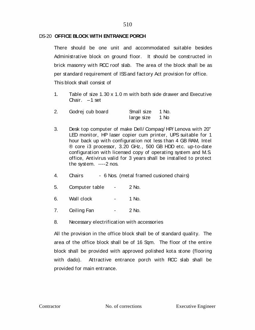
510
Contractor No. of corrections Executive Engineer
DS-20 OFFICE BLOCK WITH ENTRANCE PORCH There should be one unit and accommodated suitable besides
Administrative block on ground floor. It should be constructed in
brick masonry with RCC roof slab. The area of the block shall be as
per standard requirement of ISS and factory Act provision for office.
This block shall consist of 1. Table of size 1.30 x 1.0 m with both side drawer and Executive
Chair. – 1 set 2. Godrej cub board Small size 1 No. large size 1 No 3. Desk top computer of make Dell/Compaq/HP/Lenova with 20”
LED monitor, HP laser copier cum printer, UPS suitable for 1 hour back up with configuration not less than 4 GB RAM, Intel ® core i3 processor, 3.20 GHz., 500 GB HDD etc. up-to-date configuration with licensed copy of operating system and M.S. office, Antivirus valid for 3 years shall be installed to protect the system. ----2 nos.
4. Chairs - 6 Nos. (metal framed cusioned chairs) 5. Computer table - 2 No. 6. Wall clock - 1 No. 7. Ceiling Fan - 2 No. 8. Necessary electrification with accessories All the provision in the office block shall be of standard quality. The
area of the office block shall be of 16 Sqm. The floor of the entire
block shall be provided with approved polished kota stone (flooring
with dado). Attractive entrance porch with RCC slab shall be
provided for main entrance.
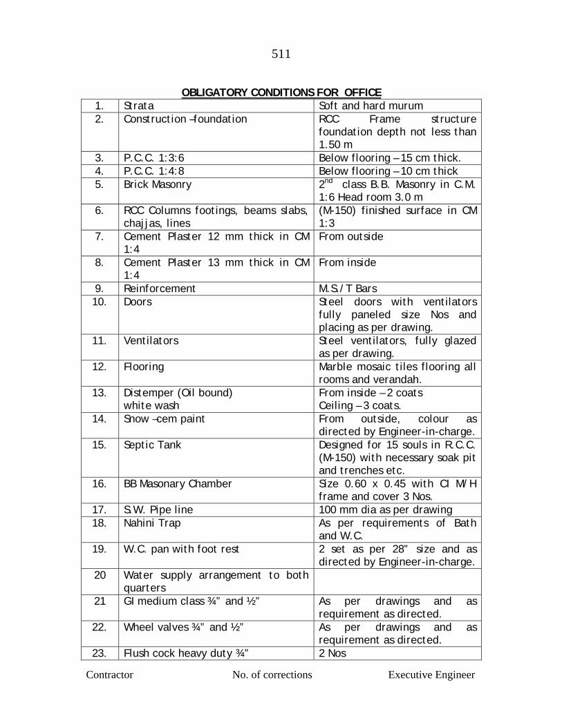
511
Contractor No. of corrections Executive Engineer
OBLIGATORY CONDITIONS FOR OFFICE
1. Strata Soft and hard murum 2. Construction –foundation RCC Frame structure
foundation depth not less than 1.50 m
3. P.C.C. 1:3:6 Below flooring – 15 cm thick. 4. P.C.C. 1:4:8 Below flooring – 10 cm thick 5. Brick Masonry 2nd class B.B. Masonry in C.M.
1:6 Head room 3.0 m 6. RCC Columns footings, beams slabs,
chajjas, lines (M-150) finished surface in CM 1:3
7. Cement Plaster 12 mm thick in CM 1:4
From outside
8. Cement Plaster 13 mm thick in CM 1:4
From inside
9. Reinforcement M.S./T Bars 10. Doors Steel doors with ventilators
fully paneled size Nos and placing as per drawing.
11. Ventilators Steel ventilators, fully glazed as per drawing.
12. Flooring Marble mosaic tiles flooring all rooms and verandah.
13. Distemper (Oil bound) white wash
From inside – 2 coats Ceiling – 3 coats.
14. Snow –cem paint From outside, colour as directed by Engineer-in-charge.
15. Septic Tank Designed for 15 souls in R.C.C. (M-150) with necessary soak pit and trenches etc.
16. BB Masonary Chamber Size 0.60 x 0.45 with CI M/H frame and cover 3 Nos.
17. S.W. Pipe line 100 mm dia as per drawing 18. Nahini Trap As per requirements of Bath
and W.C. 19. W.C. pan with foot rest 2 set as per 28” size and as
directed by Engineer-in-charge. 20 Water supply arrangement to both
quarters
21 GI medium class ¾” and ½” As per drawings and as requirement as directed.
22. Wheel valves ¾” and ½” As per drawings and as requirement as directed.
23. Flush cock heavy duty ¾” 2 Nos
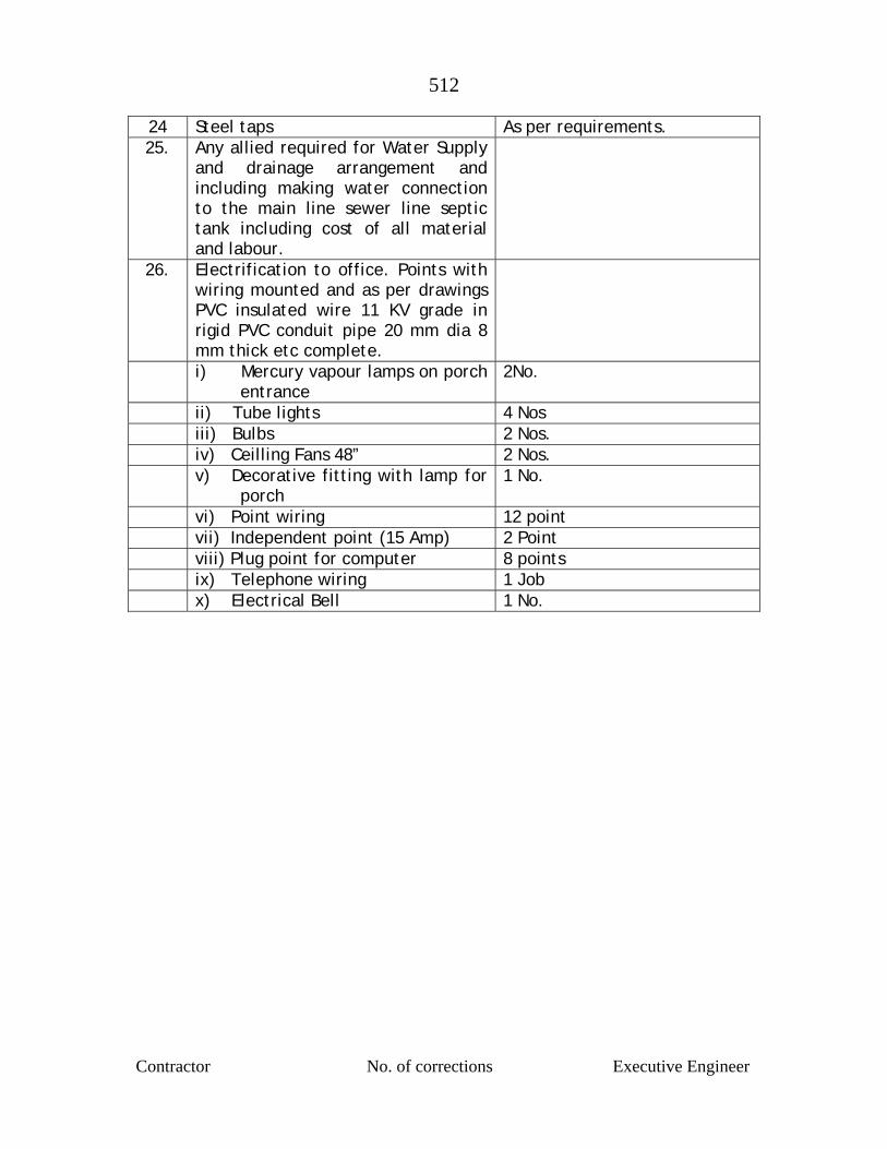
512
Contractor No. of corrections Executive Engineer
24 Steel taps As per requirements. 25. Any allied required for Water Supply
and drainage arrangement and including making water connection to the main line sewer line septic tank including cost of all material and labour.
26. Electrification to office. Points with wiring mounted and as per drawings PVC insulated wire 11 KV grade in rigid PVC conduit pipe 20 mm dia 8 mm thick etc complete.
i) Mercury vapour lamps on porch entrance
2No.
ii) Tube lights 4 Nos iii) Bulbs 2 Nos. iv) Ceilling Fans 48” 2 Nos. v) Decorative fitting with lamp for
porch 1 No.
vi) Point wiring 12 point vii) Independent point (15 Amp) 2 Point viii) Plug point for computer 8 points ix) Telephone wiring 1 Job x) Electrical Bell 1 No.
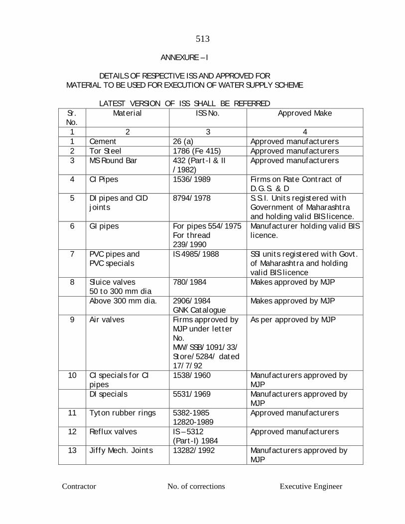
513
Contractor No. of corrections Executive Engineer
ANNEXURE – I
DETAILS OF RESPECTIVE ISS AND APPROVED FOR MATERIAL TO BE USED FOR EXECUTION OF WATER SUPPLY SCHEME
LATEST VERSION OF ISS SHALL BE REFERRED
Sr. No.
Material ISS No. Approved Make
1 2 3 4 1 Cement 26 (a) Approved manufacturers 2 Tor Steel 1786 (Fe 415) Approved manufacturers 3 MS Round Bar 432 (Part-I & II
/1982) Approved manufacturers
4 CI Pipes 1536/1989 Firms on Rate Contract of D.G.S. & D
5 DI pipes and CID joints
8794/1978 S.S.I. Units registered with Government of Maharashtra and holding valid BIS licence.
6 GI pipes For pipes 554/1975 For thread 239/1990
Manufacturer holding valid BIS licence.
7 PVC pipes and PVC specials
IS 4985/1988 SSI units registered with Govt. of Maharashtra and holding valid BIS licence
8 Sluice valves 50 to 300 mm dia
780/1984
Makes approved by MJP
Above 300 mm dia. 2906/1984 GNK Catalogue
Makes approved by MJP
9 Air valves Firms approved by MJP under letter No. MW/SSB/1091/33/ Store/5284/ dated 17/7/92
As per approved by MJP
10 CI specials for CI pipes
1538/1960 Manufacturers approved by MJP
DI specials 5531/1969 Manufacturers approved by MJP
11 Tyton rubber rings 5382-1985 12820-1989
Approved manufacturers
12 Reflux valves IS – 5312 (Part-I) 1984
Approved manufacturers
13 Jiffy Mech. Joints 13282/1992 Manufacturers approved by MJP
514
Contractor No. of corrections Executive Engineer
NOTES :- 1. In case of cement and steel, Contractor shall submit
manufacturer’s test certificate. However samples of the materials supplied by the contractor will be tested by the MJP for Govt. Engineering College/Recognised Institutes.
2. Pipes, Valves, Special etc shall be tested by CEI LTD, SGS or RITES before dispatches from Manufacturer’s places at Contractor’s cost.

515
Contractor No. of corrections Executive Engineer
ANNEXURE – II
REFERCNE OF TECHNICAL SPECIFICATIONS
Sr. No.
Short Description of Tender Item Specifications reference from book of Standard Specification of Govt. of
Maharashtra (Red Book) 1 2 3 1 Excavation in all sorts of
material Sp. No. B-1 Page No. 24 to 28 Spn IDS-1
2 Plain Cement Concrete Sp. No. B-6 Page No. 33 to 38 of Volume-I and Bd-EP No. 287 to 291 of Volume-II Spn. GS-I to GS-II
3 Masonry work (Stone masonry) Sp. No. B-9 Page No. 55 to 60 of Volume-I and BH and page of Volume-II Spn. GS-12
4 Murum Bedding Sp. No. Bd A.P No. 262 to 265 of Volume-VI IDS-6, GS-22
5 M.S. Reinforcement Grade – II or Tor Steel (Fe 415)
Stresses as per IS-456-1976 and SP. No. B-10, Spn GS-3
6 CC 1:2:4 proportion of 1:1 ½ :3 Proportion for RCC work
Page No. 62 to 65 of Vol I, IS 3370 Part-I and Part-II Sp.No. Bd-F-P No. 297 to 309 and ISA 456-1976 Spn. GS-I to GS-II
7 B.B. masonry work Sp.No.88(b) Page No. 42 Volume-I Spn. GS-13
8 Dewatering Sp. No. BR-4 Page No. 103 to 104 9 Cement plasters Sp. No. B-11 Page No. 60 to 66, Spn. GS-
15 10 Whitewash and colour washing Sp. No. BD-P-1, Page No. 411 to 412
Spn. GS-18. 11 Oil Bound Distemper etc Sp. No. BD-P-ii, P.S.P. No. 431, 414
Spn. GS-18. 12 T.W. Doors and Windows As per Sp. No.B and C 7 Page No. 418
and Spn. Bd 1-4 Page No. 479 Spn. GS-14
13 Structural Steel Sp. No. Bd-C-6, Page No. 277 Spn. GS-21 14 Rough Shahabad Stone Flooring Sp. No. Bd-M-1, Page No. 379 Spn. GS-16 15 Lowering, Laying and Jointing of
all types of pipes As per Departmental Specifications. IDS-7, IDS-8, IDS-9
Erecting flanged pipes etc Spn. IDS- 12 16 Road Surface Boxes As per type Design and Departmental
Specification Spn. IDS –16 17 B.B. masonry Chamber As per type Design and Departmental
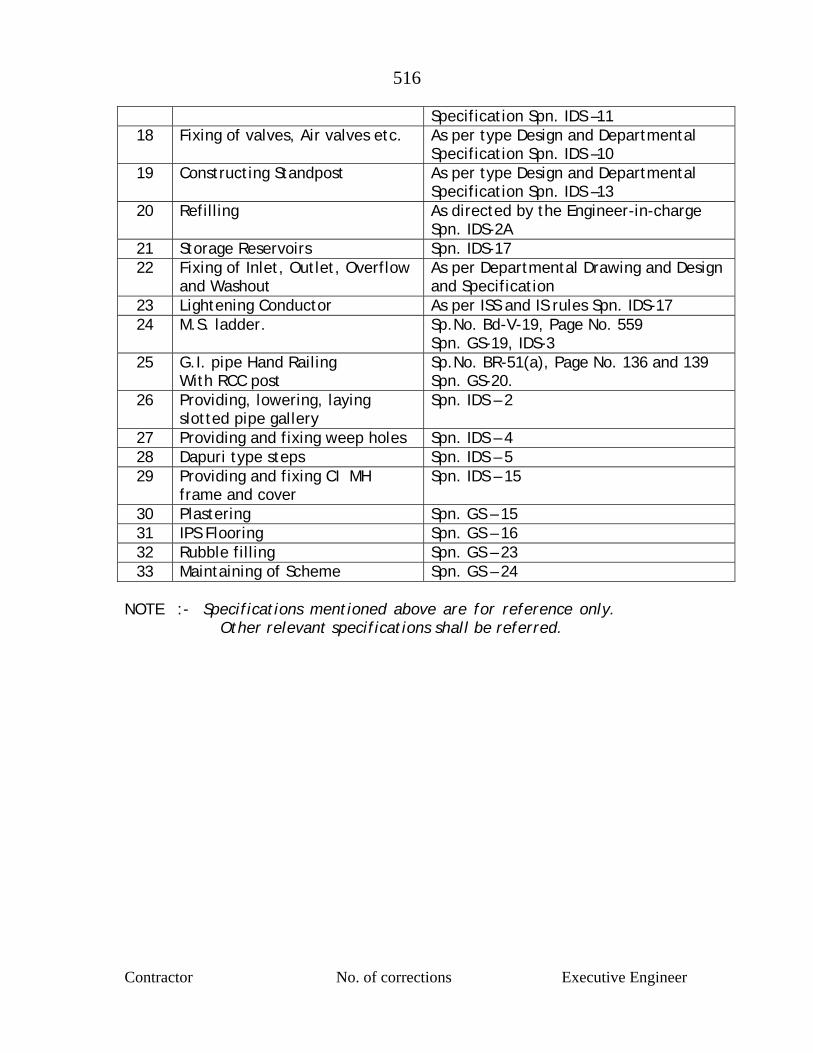
516
Contractor No. of corrections Executive Engineer
Specification Spn. IDS –11 18 Fixing of valves, Air valves etc. As per type Design and Departmental
Specification Spn. IDS –10 19 Constructing Standpost As per type Design and Departmental
Specification Spn. IDS –13 20 Refilling As directed by the Engineer-in-charge
Spn. IDS-2A 21 Storage Reservoirs Spn. IDS-17 22 Fixing of Inlet, Outlet, Overflow
and Washout As per Departmental Drawing and Design and Specification
23 Lightening Conductor As per ISS and IS rules Spn. IDS-17 24 M.S. ladder. Sp.No. Bd-V-19, Page No. 559
Spn. GS-19, IDS-3 25 G.I. pipe Hand Railing
With RCC post Sp.No. BR-51(a), Page No. 136 and 139 Spn. GS-20.
26 Providing, lowering, laying slotted pipe gallery
Spn. IDS – 2
27 Providing and fixing weep holes Spn. IDS – 4 28 Dapuri type steps Spn. IDS – 5 29 Providing and fixing CI MH
frame and cover Spn. IDS – 15
30 Plastering Spn. GS – 15 31 IPS Flooring Spn. GS – 16 32 Rubble filling Spn. GS – 23 33 Maintaining of Scheme Spn. GS – 24
NOTE :- Specifications mentioned above are for reference only.
Other relevant specifications shall be referred.

517
Contractor No. of corrections Executive Engineer
SPECIFICATIONS FOR CIVIL WORKS GES-I GENERAL :-
The following specifications shall be applicable to all the Civil Engineering Works under this contract. Items, which are covered under the following description, shall be carried out as per relevant specifications in ISS or Book of standard specifications latest edition (Government of Maharashtra Publication) and as mentioned in the proceeding pages.
GES-II MATERIAL :-
i] All the materials shall be of best and standard type as laid down in P.W.D. Hand Books Volume-I and II, Red book of B&C Department, I.S. specification and shall have to be approved by the Engineer-in-charge.
ii] LABOUR :-
All skilled and unskilled labours, supervisors, site Engineer etc shall be provided as directed by Engineer-in-charge.
GES-III GENERAL REQUIREMENT :-
i] Excavation for Well Work, Foundation Pipe Trenches Etc : As per standard specification book and P.W.D. hand book Volume I and II (Latest edition Ref-Bd-A-1 to A-10 Page No. 243 to 244 BR-3, Page No. 96-97)
ii] DEWATERING : As per standard specification book and P.W.D. hand book Volume I and II (Latest edition ) Ref-Bd-A-9 Page No. 245-246, BR-4 Page No. 97-98.
iii] R.C.C. COURSE :
All structures shall be provided with a 15 cm thick leveling course of P.C.C.M – 100 proceeding the floor slabs or foundation slabs. This course shall have an offset of 15 cms on all sides and it shall rest on strata of appropriate bearing capacity as per design.
iv] REFILLING OF EXTENDED STUFF : Sides of the structures below G.L. shall be refilled, wherever, necessary with selected murum from the excavated stuff duly watered and rammed in 15 cms layers.
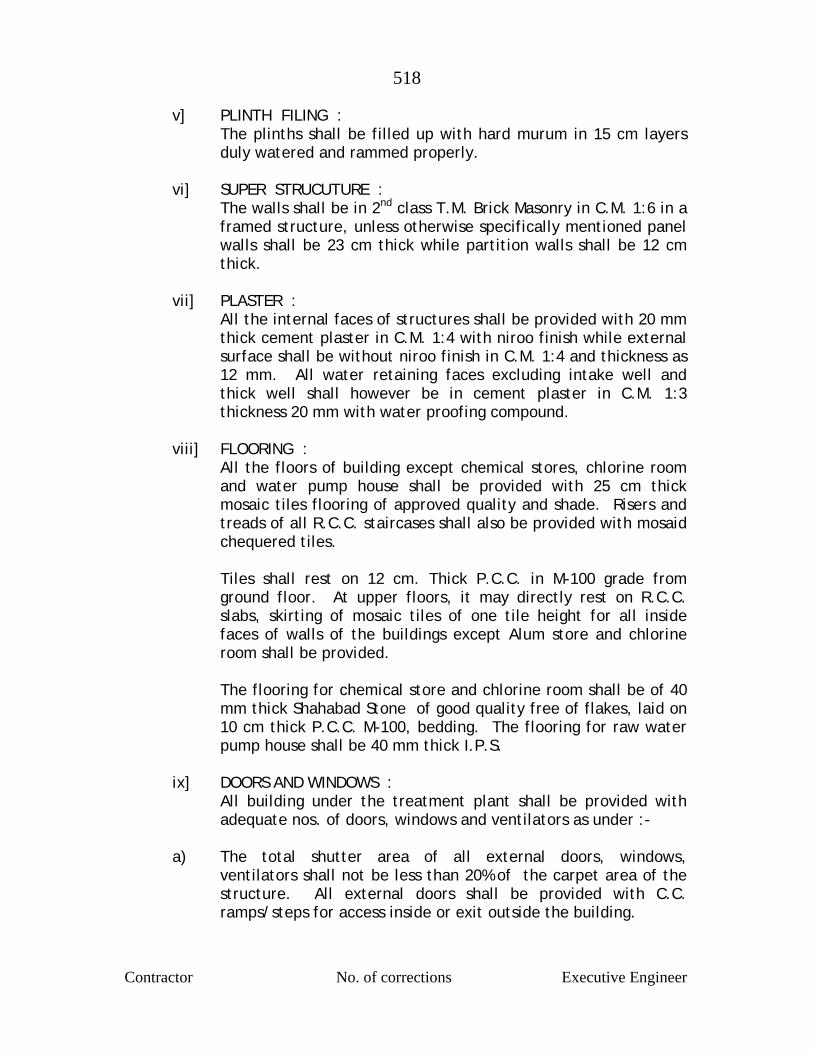
518
Contractor No. of corrections Executive Engineer
v] PLINTH FILING : The plinths shall be filled up with hard murum in 15 cm layers duly watered and rammed properly.
vi] SUPER STRUCUTURE : The walls shall be in 2nd class T.M. Brick Masonry in C.M. 1:6 in a framed structure, unless otherwise specifically mentioned panel walls shall be 23 cm thick while partition walls shall be 12 cm thick.
vii] PLASTER :
All the internal faces of structures shall be provided with 20 mm thick cement plaster in C.M. 1:4 with niroo finish while external surface shall be without niroo finish in C.M. 1:4 and thickness as 12 mm. All water retaining faces excluding intake well and thick well shall however be in cement plaster in C.M. 1:3 thickness 20 mm with water proofing compound.
viii] FLOORING :
All the floors of building except chemical stores, chlorine room and water pump house shall be provided with 25 cm thick mosaic tiles flooring of approved quality and shade. Risers and treads of all R.C.C. staircases shall also be provided with mosaid chequered tiles. Tiles shall rest on 12 cm. Thick P.C.C. in M-100 grade from ground floor. At upper floors, it may directly rest on R.C.C. slabs, skirting of mosaic tiles of one tile height for all inside faces of walls of the buildings except Alum store and chlorine room shall be provided. The flooring for chemical store and chlorine room shall be of 40 mm thick Shahabad Stone of good quality free of flakes, laid on 10 cm thick P.C.C. M-100, bedding. The flooring for raw water pump house shall be 40 mm thick I.P.S.
ix] DOORS AND WINDOWS :
All building under the treatment plant shall be provided with adequate nos. of doors, windows and ventilators as under :-
a) The total shutter area of all external doors, windows,
ventilators shall not be less than 20% of the carpet area of the structure. All external doors shall be provided with C.C. ramps/steps for access inside or exit outside the building.
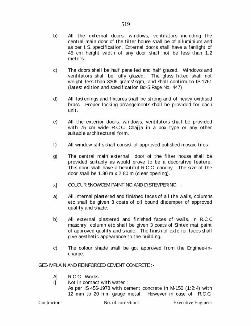
519
Contractor No. of corrections Executive Engineer
b) All the external doors, windows, ventilators including the central main door of the filter house shall be of alluminium and as per I.S. specification, External doors shall have a fanlight of 45 cm height width of any door shall not be less than 1.2 meters.
c) The doors shall be half panelled and half glazed. Windows and
ventilators shall be fully glazed. The glass fitted shall not weight less than 3305 grams/sqm, and shall confirm to IS 1761 (latest edition and specification Bd-5 Page No. 447)
d) All fastenings and fixtures shall be strong and of heavy oxidised
brass. Proper locking arrangements shall be provided for each unit.
e) All the exterior doors, windows, ventilators shall be provided
with 75 cm wide R.C.C. Chajja in a box type or any other suitable architectural form.
f) All window stills shall consist of approved polished mosaic tiles. g) The central main external door of the filter house shall be
provided suitably as would prove to be a decorative feature. This door shall have a beautiful R.C.C. canopy. The size of the door shall be 1.80 m x 2.80 m (clear opening).
x] COLOUR SNOWCEM PAINTING AND DISTEMPERING : a) All internal plastered and finished faces of all the walls, columns
etc shall be given 3 coats of oil bound distemper of approved quality and shade.
b) All external plastered and finished faces of walls, in R.C.C
masonry, column etc shall be given 3 coats of Sintex mat paint of approved quality and shade. The finish of exterior faces shall give aesthetic appearance to the building.
c) The colour shade shall be got approved from the Enginee-in-
charge. GES-IV PLAIN AND REINFORCED CEMENT CONCRETE :- A] R.C.C Works : I] Not in contact with water :
As per IS 456-1978 with cement concrete in M-150 (1:2:4) with 12 mm to 20 mm gauge metal. However in case of R.C.C.

520
Contractor No. of corrections Executive Engineer
E.S.Rs entire structure shall be constructed in M-200 grade concrete.
II] R.C.C. Worm In Contact With Water And / Or All Water
Retaining Structures :- As per I.S.S. 3370 Part-I and II and Part IV with C.C. in M-200 (1:1 1./2:3) with 12 mm to 20 mm size metal with water face side of the structure finished with 20 mm thick cement plaster in C.M. 1:3 mixed with water proofing compound.
B] MASS CONCRETE WORK : I] FOR CONCRETE BELOW LOAD BEARING MEMBER WITH PLINTH
AND FOR MAT OR LEVELING CONCRETE :- C:C 1:3:6 (M-100) with 25 mm to 37 mm gauge metal. C] FOR BUILDING LOADING STANDARD :- I.S.S. 875-1964 (Revised ) D] R.C.C. ROOF : Suitable to exposed face of the roof, water proofing compound
of standard quality and as per standard practices shall be administered.
The following specification in respect of R.C.C. and R.C.C. shall be made applicable.
MATERIALS :
A] CEMENT : Cement shall be brought by the contractor. The quantity of
cement to be used shall be as per standard proportions for various mixtures as per specifications.
B] SAND : This will consist of clean, hard, strong, durable uncoated and
well grade particles. The source of sand will be approved by the Executive Engineer and in no case clay, silt admixtures will exceed 3% by weight or volume. It shall be washed and screened if found necessary to remove excess admixtures and coarse and fine particles found in excess, screening and washing shall be done to render sand confirm to specifications if otherwise it is good. A sand shall pass through a screen with 3/16” mesh.
521
Contractor No. of corrections Executive Engineer
C] COARSE AGGREGATE : All aggregate shall confirm to either I.S. 383-1963 or I.S. 515-
1969 and should be as specified in I.S. 456-1978 vide clause 4.2 gauge and metal to be used shall be decided according to type of work by the Engineer-in-charge. It is advisable to uses black basalt metal from approved qarry.
D] STORAGE OF MATERIALS : Sand and coarse aggregate shall be properly and separately
stored on site on hard ground so as to keep them safe from admixture of foreign materials such as clay, grass etc It shall be as per I.S. 456-1978.
E] REINFORCEMENT: The steel shall be HYSD bars conforming to I.S. 1786 of 1985 for
round bars of 6 mm dia. I.S. 226 (latest edition) shall be applicable. In addition, provision of adequate anchorage length and cover in compliance with I.S. 2502-1963 and in confirmation to the approved design. Binding wire shall be provided for and used by the contractor at his cost.
F] FORM WORK : Steel centering will be preferable. If wooden formwork is used
it shall consist of planks of not less than 40 mm thickness and strong props etc . This shall be provided as per I.S. 456-1978. The timer for forms shall be best hard wood and got approved by the Engineer-in-charge. The item is covered in the rate either for plain or R.C.C. items.
G] SEPARATORS : For bottom cover of beams, slabs etc Separators of precast
cement mortar blocks of suitable size with wire embedded as directed will be used and tied to the reinforcement by wires. Between layers of reinforcement separators consisting of pieces of bars or suitable diameter shall be used. In each case the required cover to the bars will be ensured as per I.S. 456-1978.
H] WATER : The water used shall be as per I.S. 456-1978. Not more than
20 liters of water will be used for batch on one bag of cement. Approved measures for water will be provided by the contractor. The amount of water to be used will be decided by the work ability and strength consideration which will be assured by the contractor.
522
Contractor No. of corrections Executive Engineer
I] CONCRETE MIXING : The concrete shall be only machine mixed. Mixing shall be continued for atleast 2 minutes after all materials and water are placed in the drum. The drum shall revolve for 14 to 18 revolutions per minute or as specified by the maker. The capacity of the mixer will be such that a whole bag of cement is used in each batch. As a result of break-down of machine, if hand mixing has to be resorted to, only such quantity of further work as is absolutely essential in the opinion of Engineer-in-charge will be carried out. Hand mixing shall be done on a water-tight platform of sufficient large size. The required quantity of sand and cement shall be mixed dry together by turning the mixture atleast 3 times when the mixture is of uniform colour, this will than be spread over specific quantity of coarse aggregate and mixture again turned over atleast 3 times. The specific quantity of water will then be added slowly through a hose attached to the watering can, while the process of turning the mixture is being carried. The mixing shall be continued until the whole batch is of uniform consistency. For hand mixing the quantity of cement will be 10% extra.
J] PLACING :
The form will be first just moistered before placing concrete. The concrete shall be placed in position within 20 minutes after adding water to the concrete. It shall be slowly deposited in its place in uniform layers. It should generally comply with I.S. 456-1978.
K] TAMPING :
While the concrete is being placed in position it shall be vigorously rolled and tamped by bars of appropriate size and shape and by other means to assure dense and complete filling of the forms all round and in between the reinforcement. The efficiency of tamping and consolidation will be judged by complete absence of air pockets and honey combing after removal of forms and any deficiency in this respect will entail pulling down & redoing of the affected work at the cost of the contractor. For work of any magnitude or importance, mechanical vibrators of both immersion and surface type will be used as a rue and no work without them will be permitted. When concrete is so vibrated the water cement ratio will be the least practicable.
523
Contractor No. of corrections Executive Engineer
L] CURING : All R.C.C. work will be watered and kept constantly wet for at least 20 days after casting, by means of wet gunny bags and ponding as directed by the Engineer-in-charge. This operation shall start immediately after initial set of concrete.
M] REMOVAL OF FORMS :
Removal of forms will be generally as below subject to the prior approval of the Engineer-in-charge in wirting.
A] Walls, columns and
vertical side of beam : 24 to 48 hours as may be
decided by Engineer-in-charge.
Sides of beam : Three days.
Vertical walls : Six days
Bottom of slab : Eight days
Bottom of Dome : Ten days
Bottom of beam upto 5 M span
: Fourteen days
Bottom of beam above 5 M span
: Twenty one days
N] INSPECTIONS :
The work at each stage of operation i.e. completion of form formwork, completion of assembly and placing reinforcement, concereting, removal of forms, must be got inspected by the Engineer-in-charge or Sub-Divisional-Officer in-charge of the work before commencing succeeding operation in the process of R.C.C. work. Concreting of of R.C.C. members will be commenced without the written approval of the Engineer-in-charge or the Sub-Divisional-Officer in charge of the work who will record the necessary certificate to the effect in the work order book. The concreting of R.C.C. from start to finish, will be done in the presence of the Engineer-in-charge at site and for important works by the Sub-Divisional-Officer.
O] FINISH :
All R.C.C. work will be finished as provided in the items concerned. Surface not in contact with form work and not

524
Contractor No. of corrections Executive Engineer
subjected to and further finish, will be finished smooth by a float of present a uniform appearance. Surface to receive plaster or rendering will immediately on removal of forms be roughened by extensive backing for bond by a pointed tamping tool. In all case where it will be specified or not, the finish will be such as to match with rest of the structure and present a harmonious appearance to be decided by the Engineer-in-charge. All such finishing will stand included in the rate for concrete but will not be measured.
P] TESTING :
A] CUBES : On any day when concreting of M-150 and richer mix is done for 4 hours of 11 cums and more 3 concrete cubes of 15 cms will be filled per day, equally spread over the period of concrete. As a rule one cube of the three will be kept as reserved to be tested immediately after 28 day in case one of the cube tested at 7 and 28 days show unsatisfactory results. The filling and curing and testing of cubes will be at the cost of the contractor.
B] TESTING OF MATERIALS :
The contractor shall test the materials, required for R.C.C work at his own cost and submit the results to the department for according necessary approval for the same.
C] The minimum compressive straight of 15 cm filled concrete
cube shall be as under.
Max – Compressive strength of 15 cm cubes at 28 days after mixing conducted in accordance with I.S. 516-1959.
Work Test : M- 100 100 Kg/Cm2 M- 150 150 Kg/Cm2 M- 200 200 Kg/Cm2
M- 250 250 Kg/Cm2
M- 300 300 Kg/Cm2
525
Contractor No. of corrections Executive Engineer
NOTE :- Not more than 10% of the cubes tested for one particular Job shall below the above strength requirement by more than 10% and the average strength of all cubes tested shall be not less than the above figures. Failure in this regards shall be dealt with on merit of each case.
526
Contractor No. of corrections Executive Engineer
SPECIFICATIONS FOR MECHANICAL WORKS MES-I PIPE AND SPECIALS :-
All pipes and specials except for sludge drainage arrangement shall be of C.I. ‘LA’ class upto 750 mm diameter pipes shall be of M.S. plate 10 mm thickness for diameters above 750 mm which shall be epoxy painted from inside and cement mortor gunited from outside having 40 mm thickness. For sludge drainage arrangements, R.C.C. NP2 class pipes shall be used. Diameter below 150 mm of R.C.C. pipes shall not be allowed to be used anywhere. All pipes and specials which shall be laid below the floors, walls, foundations etc of plant structure shall be of mild steel only made out of 10 mm thick plates. Pipes shall be epoxy painted from inside and gunited with C.M. from outside as above.
MES-2 VALVES / PEN STOCKS / SLUICE GATES :-
All the valves shall be of C.I.D.F. type. Valves shall be Mechanical acceptable make list only. Valves shall bear the certification of I.S.I. . All the valves shall have gear arrangement for manual operations.
All sluice gates, shall be of approved make and with brass lining. It shall be provided with spur gear arrangement and hand wheel for easy manual operations.
All pen stocks shall be brass lined and provided with suitable arrangement for easy and smooth manual operation.
MES-3 G.I. PIPE RAILING :-
The railing shall consist of 32 mm dia .G.I. (Medium) pipes in number of rows as specified in the respective item. The vertical posts shall be of M.S. Angle 50x50x6 mm size having attractive appearance, placed at 2 meters centre to centre. It’s height for 1 row shall be 80 cms. While for 2 and 3 rows, it shall be 90 cms. It shall be painted in 2 coats of anticorrosive paint of approved quality and shade.
527
Contractor No. of corrections Executive Engineer
MES-4 M.S. STAIR CASE :-
The M.S. staircase shall be fabricated out of 30 cm wide stringers of 12 mm thick plates. The steps shall be 1.2 m wide of chequered plate or C.I. standard type. The tread shall not be less than 30 cms and rise not more than 20 cms 32 mm dia. Single row G.I. pipe railing 0.80 m height shall be provided on both sides. The entire assembly shall be provided with two coats of anticorrosive paint of approved quality and shade.
MES-5 M.S. LADDER :-
The M.S. Ladder shall be 0.50 m wide consisting of 75 mm x 12 mm flat stringers with 16 mm dia M.S. bars in double rows at 25 cm C/C. The item shall include all fixtures and painting with 2 coats of anticorrosive paint.
MES-6 WATER LEVEL INDICATOR :-
The mercury water level indicator shall be provided with all allied fixtures. All allied fixtures such as copper float, guide chain, pullyes. The entire unit shall be got approved form the Engineer-in-charge.
MES-7 ROLLING SHUTTERS :-
The rolling shutters shall be fabricated from 16 gauge steel latch with side guide bottom rails, brackets door suspension shaft housing box at the top including mechanical gear operation arrangements, locking arrangement shall be provided at bottom at both ends. The shutters shall be painted with 3 coats of anticorrosive paint of approved quality and shade.
MES-8 COWL VENTILATORS :-
C.I. cowl ventilators shall be of 100 mm dia and of suitable height. It shall give attractive appearance. It shall be painted with 2 coats of anticorrosive paint of approved quality and shade.
MES-9 FINISHING :-
After entire completion of the plant, all the mechanical equipment, fixtures, fastenings shall be first thoroughly scrapped and cleaned and then shall be applied with 2 coats of anticorrosive paint of approved quality and colour and shade.

528
Contractor No. of corrections Executive Engineer
MES-10 LIGHTENING CONDUCTOR -
1 No. of lightening conductors at the highest elevation shall be provided suitably for the entire plant area. It shall consist of – I) Solid copper rod upper terminal 25 mm dia 1.5 m long
with a knob at the end and with conical spikes on top. II) Suitable clamps to fix the conductor to the walls. III) Copper tape conductor 25 mm x 3 mm. IV) Earth plate 1 sqm in area and 1.5 mm thick. V) Charcoal commercial salt and sand for filling. VI) G.I. pipe of 50 mm dia upto 3 m height above G.L.
It shall include excavation for the trench to the required depth, filling with charcoal, salt and sand and excavated stuff, all the labours necessary fixtures etc, as per instructions of the Engineer-in-charge.
MES-11 FIRE EXTINGUISHERS -
In all sufficient numbers of fire extinguishers shall be provided one each in Panel Board Room, wash water pump room, laboratory , filter house. Each unit shall have a capacity of 10 liters. It shall be of reputed make and shall be approved by the department.
529
Contractor No. of corrections Executive Engineer
SPECIFICATIONS FOR ELECTRICAL WORKS ES-I GENERAL :-
All the electrical installation both internal and external shall be carried out as per Indian electricity rules, 1956 and subsequent amendments made to it from time to time.
The work shall be carried out through a licensed electrical contractor registered with the Government of Maharashtra All the electrical installations shall be got approved, tested and certified from the Electrical Inspector of Govt. of Maharashtra, by the contractor at his own cost. The damages caused to the civil structures etc during electrical installations, shall be made good by bringing such locations to their normal condition i.e. original finish at no extra cost. All the material used for electrical installation shall be of standard type and of reputed make as specified at relevant places hereafter. All the materials shall be got approved from the Engineer-in-charge before it is used on the work. All safety measures shall be adopted for all the installation as per India electrical rules e.g. providing adequate earthing, proper insulation etc. The layout of the internal and external electrification of the entire plant shall be got approved form the Engineer-in-charge well in advance. Necessary modifications shall have to be carried out as per instructions of the department, at no extra cost.
All the external and internal electrical installations shall be properly screwed to poles and walls respectively to withstand storm, rains etc. The electrical installations internal and external shall be adequate and should have decorative finish keeping in view of atchitecuturer beauty of the civil structures. The entire electrical installation both internal and external shall be commissioned to the satisfaction of the Engineer-in-charge without any extra cost and shall be covered with guarantee for
530
Contractor No. of corrections Executive Engineer
12 calendar month for its performance, design, equipment and workmanship from the date of commissioning.
ES-II SCOPE OF WORK :-
The job involved in this consists of providing erecting and commissioning of electrification for all the treatment plant structures and yard area as per sub work schedule-B. It also includes electrification and motivation of all the allied equipment of WTP fixtures and accessories. Adequate electrical power at 400/440 volts 50 c/s shall be made available for such work to the contractor, who will design and install the panel board for entire internal and external electrification and power requirements to the prime movers of all mechanical equipment of Treatment plant e.g. Alum solution tank, flash mixture equipments, wash water pump etc. The contractor shall have to install his panel board in a separate room i.e. within the are of chemical house on ground floor. In no case this main panel board shall be allowed to be installed in pure water pump house. Adequate illumination shall be provided both internal and external. Sufficient No. of plug points shall be provided. The external electrification will be done by laying underground cables as per standard practice and as per I.E. rules. The minimum illumination to be provided shall be as detailed out under individual item later on hereafter.
ES-III ITEMWISE REQUIREMENTS :- 1] MOTORS
All the prime movers required for mechanical equipments of water treatment plant would be of suitable H.P. considering 30% over loading by all means 3 phase squrrel cage induction motors, working on 440 volts, 50 c/c, 1400 RPM class of insulation ‘B’ I.S.I. make only motor shall be of Kirlosker make only. RECOMMANDED MAKE : KIRLOSKAR, JYOTI, CROMPTON. 2] STARTERS : Direct on line starters for motors upto 5H.P. and fully automatic Star Delta starter upto 25 HP shall be provided. Recommended Make :- As per Mechanical Acceptable List only 3] PANEL BOARD :
531
Contractor No. of corrections Executive Engineer
a] Main Distribution Board The panel board shall be designed for the complete electrical load of Treatment works e.g. for prime Movers of mechanical equipment of flash mixer, clariflocculator with its end carriage. Alum and lime solution tank, Bleaching powder solution tank, wash water pump. Air blowers, sampling table etc and for entire load of internal and external electrification e.g. lights, floodlights, M.V. lamps, ceiling fans, cooling fans, coolers etc. It shall consist of 4 bus bars of suitable section of copper designed for capacity considering above. Electrical load, Ammeters and Voltmeters of suitable range with rotary selector switches phase indicator lamps with switches MCCB and TPN switches of adequate capacity with HRC fuses. The panel board shall be closed type with panel opening either from the front or rear side for carrying out inspection, operation and maintenance. Suitable TPN rewirable fuse unit of adequate capacity shall be provided for lighting load. This panel for board shall be housed in a room constructed separately for this purpose but as per direction of the Engineer-in-charge. The Incomes of all panel shall be 4 pole MCCB upto 800 Amt and ACB above 800 Amp. b] Panel Board for Blower Room The panel board designed for the blowers shall have bus bar chamber, phase indicator lamps with switches ammeter, voltmeter of suitable range with rotary switch and star delta starter with single phase preventor unit and TPN main switches of adequate capacity and of HRC type. c] Wash Water Pumps Panel Board The panel board for wash water pumps shall have bus bar chamber, phase indicator lamps with switches ammeter, voltmeter of suitable range with rotary switch and star delta starter with single phase preventor. TPN main switches of adequate capacity with HRC fuses etc and shall be housed as per direction of the Engineer-in-charge. d] Clariflocculator panel board The panel board shall be installed on the bridge of the clariflocculator and should be water proof and weather proof. It shall consist of main switches of adequate of or star delta starter as the case may be including the switches for fluorescent lights on bridge.
532
Contractor No. of corrections Executive Engineer
e] Flash Mixer The panel board for flash mixer shall consist for main switch of adequate capacity with HRC fuses, DOL/star delta starter and single phase preventor. f] Alum Mixing Mechanism : The panel board shall also include main switch of adequate capacity with HRC fuses, FSAD / DOL star delta starter and single phase preventor. The location of all above panel boards shall be at places considering the operating convenience and shall be properly installed and as per direction of the Engineer-in-charge. Suitable DOL / FASD starters as the case may be shall be suitably installed in panel and panel shall be provided M.S. stand specially fabricated for the purpose. mended Make :- Switchgear and all other allied equipment of the panel shall be as per Mechanical Acceptable Make list only. 4] CABLES : For connecting motor of various H.P. and panel boards suitable 3½ core aluminium armoured cable of adequate capacity with regard to starting current of motor shall be provided and shall be of reputed make (ISI marks) and laid as per standard practice in a channel as per Indian Electrical Rules. Recommended make : As per Mechanical acceptable make list only. 5] WIRING : a] Internal Point wiring with 2x15 sqm. PVC aluminium conduit insulated and PVC SHEATHED aluminium wire shall be provided in a M.S. conduit of 16 gauge and 25 mm dia with continuous G.I. earth wire of 14 S.W.G. complete with shock proof accessories erected on polished T.W. block. The M.S. conduits shall be painted with 2 coats of anticorrosive black paint alongwith specials e.g. bends, tees, Cross, Elbows, Inspection and distribution covers, Cut out etc shall be provided. Recommended make : I] PVC SHEATHED WIRES : Aluminium conductor 250/440 volts, grade paramite, Nic/Henlay Gloster, Finolex, Alin Phroyex.
533
Contractor No. of corrections Executive Engineer
II] Conduit pipes : National, Khandelwal, Philips. b] External a) All the external wiring will be done by using cable of suitable
section 31/2 core, aluminium, armoured cable suitable erected with earthing in ground below 80 cms with necessary screened sand column 15x15 cm and cable placed exactly at centre of the sand column and brick placed at both sides and top of the sand column as per I.E. rules. Suitable cable and cable boxes glands shall be provided. Recommended make : As per Mechanical acceptable make list only.
b) Poles : i. Poles for street light shall be G.I. heavy duty swaged weded
pole and of 100x75x50 mm dia 5.5 mtrs long and suitably bent at top as per standard practice and of suitable sectional lengths. The erection of pole shall included excavation with 0.6x0.6x1.5 cm. Deep and embedded in cement concrete foundation in 1:3:6 ration with 40 cms. plinth. The poles shall be spaced at a distance not more than 30 mtr from centre to centre to cover the entire premises as directed.
ii. All necessary fixtures with necessary G.I. light post, clamps, nuts and bolts, screws, insulators with kit-kat type fuse unit of suitable capacity shall be provided. Suitable earthing shall be provided to the poles.
Paintings : All the poles shall be nicely painted with one coat of red oxide and 2 coats of superior quality of anticorrosive paint.
c) For illumination on bridges of clariflocculator, the cables of
1.5 sqmm 2 core aluminium aromoured cable shall be used with all necessary fixtures e.g. Glands, Clamps etc. The make of cable is as per mechanical acceptable make list only.

534
Contractor No. of corrections Executive Engineer
6] ILLUMINATION : a] Industrial fluorescent lights and fittings I] Internal White stove enamelled industrial type fluorescent fittings of 22 gauge M.S. sheet open ended reflector complete with 1.2 mtrs (4Ft) x 40 WATTAS TUBE starter and polyster heavy duty choke, with decorative cover completely wired up with holders erected on T.W. Block. It shall be mounted with two ball suspension places flush with ceiling, with all its accessories e.g. ceiling rope, etc at places as directed. It shall be mounted in zig zag pattern on walls, where suspension type is not possible but exclusively as per direction of the Engineer-in-charge. The rate illumination shall be 40 watts / 10 sqm. b] FLOOD LIGHTS General purpose flood lights fitting of weather proof and water proof construction, suitable for and with 500 watts bulb, Duoflux type reflector anodised aluminium sheet spun anodised with well polished interior reflecting surface with holder of thread type, mounted on M.S. poles of 80 mm, 6 mtrs. Long suitably earthed and with necessary fixtures in on approved manner, 15 amps 230 volts, ICDP switch shall be provided and housed in suitable M.S. Box, water proof at an operating level. Total 8 Nos. flood lights shall be provided. One No. of flood light at the corner of chemical house shall be installed for lighting the Aeration fountain. The reflector for flood lights shall be Duoflux type designed for a long and proper focus, in all 3 Nos. of flood lights shall be provided with Duoflux reflector and mounting clamps. Recommended make : Philips, Mazda, Osram, Bajaj, Crompton and of 500 watts suitable for 50 C/s, 230 volts. C] SODIUM VAPOUR (HPSV) LAMPS (For External and Street) Water light and un-eather proof 150 watts HPSV lamps fitting with sodium vapour lamp having deep drawn one piece aluminium body nickel plated reflector with clear acrylic cover and necessary control gear and electronic igniter etc with necessary wiring complete with accessories such as copper wound choke, condenser etc with fancy bracket of GI pipe suitably erected on 80 mm dia x 6 mtr long M.S. pole (with
535
Contractor No. of corrections Executive Engineer
suitable Base Plate at bottom and pole top for fixture fitting) suitable embedded in foundation properly earthed and at position as directed by Engineer-in-charge. Total 25 Nos. HPSV lamps shall be provided. The HPSV lamps shall be spaced not more than 30 mtrs centre to centre. Recommended make : Philips, Crompton, G.E.C. Bajaj.
D] AUTOMATIC EMERGENCY LIGHTING 2 Nos of automatic emergency light units with flexible cord and 3 pin plug of reputed make suitable for 230 volts shall be provided. Recommended make : Quality, Morlex, Bajaj etc. 7] FANS : I] CEILING FANS : Ceiling fans of approved type with condenser AAC 50 cycles/second 230 volt and 1400 mm (56”) sweep complete with all fixture e.g. fan clamps, M.S. flats and down rod of required length. The down rod shall be long enough so that a clear distance between the floor and the fan blades shall not exceed 2.6 mtrs. The ceiling fans shall be provided for every 30 cum of structure volume and located as per directions of the Engineer-in-charge. Ceiling fans shall be provided to all the buildings of the plants as per Schedule-B except stores, sanitary block and the portion of fitter beds only as per direction of Engineer-in-charge. Recommended make : G.E.C., Usha, Rallies, Crompton, Orient fans with regulators of same make. II] EXHAUST FANS : Exhaust fans of 45 cms (18”) 230 volts, 50 C/s 1400 RPM, with condenser unit and complete with all its accessories fixtures shall be provided and erected in such a fashion to displace 130 cum/minute of air for a cycle of every 5 minutes. The location of the exhaust fans shall be as per the directions of the Engineer-in-charge. Metal sheet cowl for exhaust fans recess 45 cms. Fabricated from suitable frames 25x25x3 mm angle covered with 22 gauge G.I. sheet and opening covered by expanded metal, the cowl to be fixed to wall with grouted bolts
536
Contractor No. of corrections Executive Engineer
of 9 mm dia and 12 cms length and nuts, exhaust fans shall be provided in pure water pump house, chlorine room, chemical house, chemical stores, sanitary blocks etc. Approved Make : G.E.C. Crompton, Rallies, ACCO. 8] EARTHING : Earthing for electrical installation both internal and external, including panel boards and motors with adequate capacity of G.I. wire of suitable gauge shall be provided at all suitable places and all earthing stations shall be inter connected so as to ensure maximum safety and G.I. plate, charcoal, salt etc shall be used as per Indian Electricity Rules. The earthing wires will run along conduits upto plug points and as per the directions of the Engineer-in-charge. Earthing chamber shall be constructed from brick work and consist of funnel, C.I. cover etc. complete. 9] SWITCH BOARD WITH SWITHCES FOR BUILDING WIRING : Piano type switches and 3 pin plugs shall be provided and properly fixed on polished T.W. block of suitable size with sunmica top. Sufficient number of such switch boards for operating covenience shall be provided with indications of fans, lights etc on it.
10] POWER WIRING : Power wiring with suitable numbers of plug points and switches of 15 Amps, 230 volts, suitable for operation of electrical blowers, drilling machine and grinder shall be provided only in pump house. This shall be in addition to the general plug point provided.

537
Contractor No. of corrections Executive Engineer
SPECIFICATION FOR ELECTRICAL INSTALLATIONS 1) GENERAL
1. All the electrical installations, both internal shall be carried out as per Indian Electricity Rules, 1956 and subsequent amendments from time to time.
2. The work shall be carried out through a licensed electrical
contractor registered with Government of Maharashtra. 3. The damages caused to the civil structures etc. during electrical
installation shall be made good by bringing such locations to their normal condition i.e. original finish at no extra cost.
4. All the materials used for electrical installations shall be of
standard type and of reputed make specified at relevant places hereafter. All the materials shall be got approved from the Engineer-in-Charge prior to the supply.
5. All safety measures shall be adopted for all the installations as
per Indian Electricity Rules i.e. providing adequate earthing, proper installation, etc.
6. The general layout of the internal and external electrification of
entire plant shall be got approved from the Engineer-in-Charge, well in advance. Necessary modifications shall have to be carried out as per instructions of the Department at no extra cost. The tender drawing, if provided is indicative, however, the contractor shall justify his layout tender specifications.
7. All the external and internal electrical installations shall be
properly fixed to poles and walls respectively to withstand storm, rains etc.
8. The electrical installations, internal and external shall be
adequate and should have decorative finish, keeping in view architectural beauty of the civil structure.
9. The entire electrical installations, both internal and external
shall be commissioned to the satisfaction of the Engineer-in-Charge without any extra cost and shall be covered with guarantee for 12 calendar months for its performance, design equipments and workmanship, from the date of commissioning.
538
Contractor No. of corrections Executive Engineer
2) SCOPE OF WORK The job involved consists of providing, erecting and commissioning of
electrification with necessary allied equipments and its accessories for
entire plant structures as per Annexure attached to the tender both
external and internal including yard premises of the treatment plant.
The agency has to made his own arrangement for electric supply per
construction purpose. Department will made available electric supply
for commissioning and operation of plant, however, agency shall
liaison with power supply authority for releasing the electric supply at
water treatment plant. The Contractor shall have to install his panel
board in a separate room in the filter house to be constructed by him.
Adequate illumination shall be provided both for internal and external
areas. Sufficient Nos. of plug points shall be provided on board.
External electrification will be done by laying underground cables and
internal wiring shall be carried out in PVC conduit as per Indian
Standard Rules. The scope also includes the essential items of work
and material required but not specified anywhere in specification. All
control panels shall be installed away from chlorine vapour influence
area.
The makes of all mechanical/ electrical components shall be as per the
visited only. Equivalent makes are not acceptable. ITEMWISE REQUIREMENTS 1. Motor All the prime movers required for mechanical equipments of water
treatment plant would be of suitable HP, squirrel cage induction
motors, working on 440 Volts, 3 Ph.50 Hz., minimum. class of
insulation for motors shall be ‘B’ and construction as per IS:325. The
motors for outdoor installation shall be of degree of protection IP
54/55 or superior and continuous duty.
539
Contractor No. of corrections Executive Engineer
Recommended makes : Kirloskar/Siemens/Joyti/Crompton/GEC/NGEF 2. Starters Direct online starters for motors upto 5 HP shall be provided. Above 5
HP and upto 50 HP, star delta shall be provided, for motor above 50 HP
auto transformer starter shall be provided, these starters shall be of
fully automatic.
Recommended makes LT/LK, Siemens/Kulburn/MEI/Jyoti. 3. Panel Board a) Main Distribution Board A cubical sheet metal enclosed panel comprising 415 V switch
gear and control gear shall be suitably designed for functions as under.
i) Reception of power from pump house by providing and laying
adequate size 3.5 core aluminium armoured cable. ii) Distribution of power to filter house, chemical houses and
lightening purpose etc. This switch gears and controls gears components shall be The design and components of this panel shall be for approved prior to
its fabrication. i) One No. adequate Capacity MCCB for reception of power shall
be front operated and shunt release type. ii) Outgoing feeder for (a) air blower, (b) wash water pumps (c)
electrical circuits for flash mixer, clarifier, bridge chemical dosing arrangement external illumination and internal illumination etc. (separate feeder for each of the above with adequate spare feeders)
Panel Construction The 415 Volts control gears shall be housed in totally enclosed sheet
metal clad vermin and dustproof cubicles suitable for floor mounting.
The panel shall incorporate the following.
540
Contractor No. of corrections Executive Engineer
i) 415 Volts suitable sized bus-bars with neutral housed in enclosed
compartment horizontal/vertical formation. ii) Inter panel barriers in the bus bar chamber shall be of epoxy
painted. The panel shall be fabricated from MS sheets 2 mm thick. Hinged doors shall be provided at the front and rear with car type handles. Mechanical interlock shall be provided to prevent opening of the front door or alternative arrangement shall be provided to trip supply in event of opening of the front door. Suitable stopper shall be provided to restrict opening of the door an scratching of paint with adjoining panel structure. Cable entries and exists shall be from bottom. The indicating and operating devices shall be preferably at uniform levels and shall not be above 1600 mm from floor levels.
The drawing, of the panel shall be submitted and got approved
from the competent authority before fabrication. The same shall be tested in the factory before brought to site.
The panel frame work shall have minimum ISMC 75 base channel. 4. Capacitor Adequate capacity power factor improving capacitors for
blowers, wash water pump and bridge and flash mixer motor
shall be provided and commissioned.
5. Earthing Ground bus of section not less than 50 x 4 mm G.I. flat and
shall be bolted to the frame work at minimum 2 places.
Earthing arrangement shall be provided inside each cubical
to ensure tank is earthed in all positions of the tank.
6. Painting The panel shall be painted as under Prime coat One coat of red oxide Intermediate coat Enamel paint of shade approved by the Engineer
541
Contractor No. of corrections Executive Engineer
Final coat As Above 7. Labels and danger mark Scheme of labeling shall be as under i) Each compartment door shall have title label. The
component/control on each compartment shall have function label.
ii) Each internal component and fuse shall have identification label
with fuse current capacity where applicable. All external labels shall be clear painted black in English. All internal
labels shall be multi-layered plastic. All labels shall be affixed with
chrome plated nuts and bolts. Size of labels shall be 50 x 25 mm
minimum with height of letters as 5 mm.
Compartment not interlocked to an insulator shall have an external
danger mark as under.
8. ‘Danger Live Terminal’ with flash mark and volts in red letter on white
background 9. Mat and hand gloves Electrical grade rubber mat 6 mm thick suitable for 22 KV extending
full length of each panel shall be provided. The requirement shall be
applicable for all L.T. panels and starter panel. One pair of rubber
hand gloves with no joint, suitable for 22 KV duly tested shall be
provided.
Specification of Components 1. MCCB shall be of (i) LT /EE, Telemechanie/ Siemense/C&S only 2. Digital Ammeter with 96 Sqmm size with CT having suitable ratio 3. 0 - 500 Volts digital Voltmeter of size 96 Sq.mm.

542
Contractor No. of corrections Executive Engineer
Switch and Fuse Unit The switch an fuse units shall conform to IS:4047 and IS:4237. They shall be
double break, quick break type designed to break under full load condition.
All switches shall have ON and OFF indication. Mechanical interlock shall be
provided to prevent inadvertent opening when ON.
All fuses shall be HRC and or link type. Indication for state of fuse shall
conform to IS:2208.
Indicating Lamps All indicating lamps shall be of low voltage with series resistance. The lens
shall be polycarbonate, oil and dust proof, unbreakable and of suitable
colour. The arrangement shall permit removal of lenses and bulbs from front.
All laps shall be protected with individual fused circuit. However LED
indicating lamps are preferable.
Meters The digital ammeters and voltmeters shall be dust and water tight with
plastic windows and of accuracy Class-I as per IS:1248. They shall be flush
mounted on panel. Size of the meter shall be 96 Sqmm. Combined digital
meter for current voltage and frequency shall be acceptable.
Inspection The panel shall be offered for inspection and tests to the Engineer-in-Charge
at manufacturers works as under.
i) Complete panel after assembling. ii) HV test on power and control circuits. iii) Simulation test of check functioning of control. Documents
543
Contractor No. of corrections Executive Engineer
i) Final dimensional, schematic and wiring drawing or panel board an test reports shall be submitted to the Engineer-in-Charge in 5 copies.
ii) Constructional, schematic and wiring drawings and operation and
maintenance for MCCB shall be submitted to the Engineer-in-Charge in 3 copies.
Panel Board for Blowers The panel shall be cubical type. The panel board designed for the blowers
shall have bus bar chambers, phase indicator lamps with switches, ammeter,
voltmeter of suitable range with rotary switch and suitable starter with single
phase preventor unit and ICTP main switches of adequate capacity and fuses.
Panel Board for Clariflocculator The panel shall be double door cubical type. This panel board shall be
installed on the bridge of clariflocculator and should be waterproof and
weatherproof. It shall consists of main switches of adequate capacity with
HRC fuses, direct online starter or star delta starers as the case may be etc,
including the switches for fluorescent lights on bridge. The canopy not less
than 14 SWG sheet shall be fitted to panel box.
Panel Board for Flash Mixer The panel shall be of double door cubical type. The panel board for flash
mixer shall consist of main switch of adequate capacity with HRC/fuses, star
delta starter and single phase presenter. The panel board should be water
proof and weather proof. The canopy shall be fitted to panel box.
Panel Board for Alum Mixing Mechanism. The panel shall be cubical type. The panel board shall also include main
switch of adequate capacity with HRC fuses, star delta and single phase
preventor. The canopy shall be fitted to panel box.
Note: The location of all above panel board shall be placed considering
convenience and shall be properly installed as per directions of the Engineer-
544
Contractor No. of corrections Executive Engineer
in-Charge. Suitable starters, DOL, Star Delta or auto transformer starter as
the case may be shall be suitably installed in Panel board.
Cables The base of 3.5 core upto panel and further from panel to motor, cable of 3
core aluminium armoured cable of adequate capacity with regard to starting
current of motor shall be provided and shall be of reputed makes conforming
to IS 1554:1964 and laid as per standard practice in a channel as per Indian
Electricity Rules. All cables shall be sized considering duct rating and shall
have minimum 10% current margin above duct rating. The voltage drop
should be restricted to 10 Volts. The cables schedule should be submitted to
the MJP and got approved before procurement and starting the cable work. A
stand-by cable from adequate place to panel to panel shall be provided and
laid for clarifier bridge panel.
Recommended Makes: Incab/Gloster/Tropodur/Finolex/Asian/CCI Wiring Internal Point wiring 1-1.5 Sqmm PVC sheathed FRIS glade wire shall be provided in a
PVC conduit of 20 mm dia. With continuous GI earth wire of 14 SWG complete
with shock proof accessories erected on Formica topped TW block PV conduit
pipe and all necessary conduits specials e.g. bends, tees and cross, elbows,
inspection and distribution covers, cutout etc. shall be provided. Generally
as specified in PWD electrical red book under specifications EG PW/SW
Recommended makes a) PVC sheathed wires : Multistrand copper conductor 660/440 Volts grade Glostaer Finolex make b) PVC conduit pipe ISI mark
545
Contractor No. of corrections Executive Engineer
External All the external wiring will be done by using cable of suitable size 2 core,
aluminium armoured cable suitably laid in ground below 60 cm with necessary
screened sand columns of 15 x 15 cm and cable placed exactly at center of
the sand column an bricks placed on both sides and top of the sand column as
per Indian Electricity Rules, suitable cable and cable boxes, glands shall be
provided. Adequate size loop shall be provided at terminal points. The cable
shall be paid as per specification No. CB-LT/AL and PWD Electric Red book.
Recommended Makes Gloster, Tropodur, Incab, Finolex, Asian Polycab Poles a) Poles for street light shall be of G.I heavy duty swage welded ones end
of 100 x 74 x 50 mm dia. 6 m long with suitable bend at top as per standard practice. The erection of pole shall include excavation with 0.6 m x 0.6 m x 1.5 m deep and embedded in cement concrete foundation in 1:3:6 with 40 cm plinth. The poles shall be spaced at a distance not more than 20 m center to center along the road and in area requiring lighting. The installation shall be made as specified in PWD red book specification No. OH-PL/GIP.
b) All necessary fixtures with G.I. light post, clamps, nuts and bolts
screws insulators with kit-kat fuse unit of suitable capacity shall be provided. Suitable earthing shall be provided to the poles.
c) Painting : All the poles shall be nicely painted with one oat of red
oxide and 2 coats of superior quality anticorrosive Silver paint. d) For illumination on bridge of clariflocculator 1.5 Sqmm, 2 core
aluminium armoured cable shall be used with all necessary fixtures e.g. glands, clamps etc.
Illumination Internal The minimum illumination level shall be made as specified. The fixtures used
for internal illumination shall preferably be stove enameled box/powder
coated box type fluo. Fitting with 36/40 W tube light and electronic ballast as
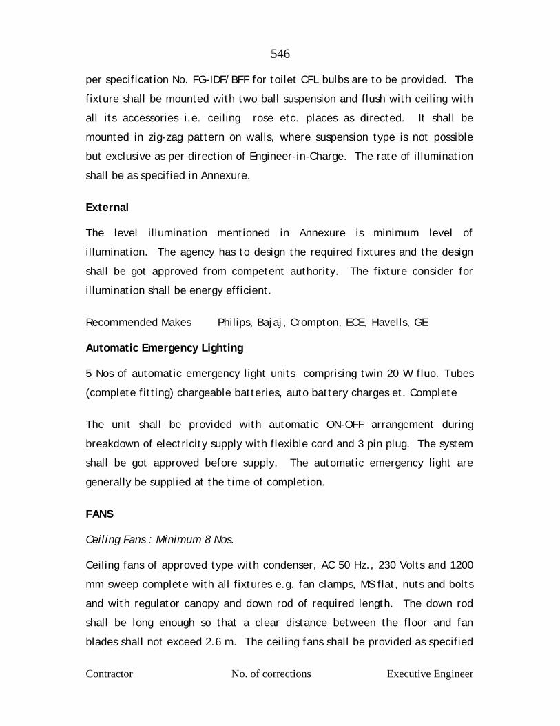
546
Contractor No. of corrections Executive Engineer
per specification No. FG-IDF/BFF for toilet CFL bulbs are to be provided. The
fixture shall be mounted with two ball suspension and flush with ceiling with
all its accessories i.e. ceiling rose etc. places as directed. It shall be
mounted in zig-zag pattern on walls, where suspension type is not possible
but exclusive as per direction of Engineer-in-Charge. The rate of illumination
shall be as specified in Annexure.
External The level illumination mentioned in Annexure is minimum level of
illumination. The agency has to design the required fixtures and the design
shall be got approved from competent authority. The fixture consider for
illumination shall be energy efficient.
Recommended Makes Philips, Bajaj, Crompton, ECE, Havells, GE Automatic Emergency Lighting 5 Nos of automatic emergency light units comprising twin 20 W fluo. Tubes
(complete fitting) chargeable batteries, auto battery charges et. Complete
The unit shall be provided with automatic ON-OFF arrangement during
breakdown of electricity supply with flexible cord and 3 pin plug. The system
shall be got approved before supply. The automatic emergency light are
generally be supplied at the time of completion.
FANS Ceiling Fans : Minimum 8 Nos. Ceiling fans of approved type with condenser, AC 50 Hz., 230 Volts and 1200
mm sweep complete with all fixtures e.g. fan clamps, MS flat, nuts and bolts
and with regulator canopy and down rod of required length. The down rod
shall be long enough so that a clear distance between the floor and fan
blades shall not exceed 2.6 m. The ceiling fans shall be provided as specified

547
Contractor No. of corrections Executive Engineer
in PWD specification FG-FN/CF with electronic step regulator and fixed.
Ceiling fans shall generally provided for all the building of the plant stores
and the portion of filter house. All ceiling fans should be at one make only.
Recommended Make GEC/Usha/Rallis/Crompton/Orieng fans with regular of same make. Exhaust Fans: Minimum 12 Nos. Exhaust fans below mentioned size with condenser unit and complete with all
its accessories and necessary fixtures shall be provided and erected. The
location of the exhaust fans shall be as per the direction of the Engineer-in-
Charge. Metal sheet cowl for exhaust fans recess 375 mm dia fabricated from
suitable frames of 25 x 25 x 3 mm angle, covered with 22 gauge GI sheet and
opening covered by expanded metal, mechanism shall be provided. The cowl
to be fixed to wall with grouted bolts of 9 mm diameter and 12 cm long and
nuts.
1. Chlorine room 4 Nos. (375 mm 900 rpm) 2. Filter gallery and above filter water 2 Nos. (375 mm 900 rpm) 3. Filter house 2 Nos (150 mm 400 rpm) 4. Laboratory 1 No. (225 mm 1400
rpm) 5. Sanitary block 2 Nos (225 mm 1400 rpm) Exhaust fan shall generally be as per specification No.FG-FN/EXE 100 Sr.1 to 3 Approved makes GEC/Crompton/Ralies/Almonard Earthing Earthing for electrical installation both internal and external, including panel
boards and motors with adequate capacity of aluminium wire of suitable
gauge shall be provided at all places an all earthing stations shall be
interconnected so as to ensure maximum safety and GI plate, charcoal, salt
etc. shall be used as per Indian Electricity Rules and as per IS:3043:1966, the
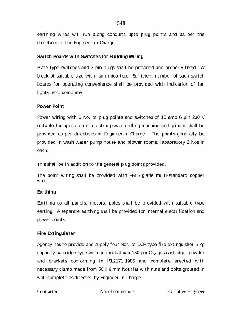
548
Contractor No. of corrections Executive Engineer
earthing wires will run along conduits upto plug points and as per the
directions of the Engineer-in-Charge.
Switch Boards with Switches for Building Wiring Plate type switches and 3 pin plugs shall be provided and properly fixed TW
block of suitable size with sun mica top. Sufficient number of such switch
boards for operating convenience shall be provided with indication of fan
lights, etc. complete
Power Point Power wiring with 6 No. of plug points and switches of 15 amp 6 pin 230 V
suitable for operation of electric power drilling machine and grinder shall be
provided as per directives of Engineer-in-Charge. The points generally be
provided in wash water pump house and blower rooms, labaoratory 2 Nos in
each.
This shall be in addition to the general plug points provided. The point wiring shall be provided with FRLS glade multi-standard copper wire. Earthing Earthing to all panels, motors, poles shall be provided with suitable type
earting. A separate earthing shall be provided for internal electrification and
power points.
Fire Extinguisher Agency has to provide and supply four Nos. of DCP type fire extinguisher 5 Kg
capacity cartridge type with gun metal cap 150 gm Co2 gas cartridge, powder
and brackets conforming to ISL2171:1985 and complete erected with
necessary clamp made from 50 x 6 mm Nos flat with nuts and bolts grouted in
wall complete as directed by Engineer-in-Charge.

549
Contractor No. of corrections Executive Engineer
Painting All structural work shall be painted with one coat of primer paint and two
coats of epoxy/enameled paint prior to commissioning of plant.
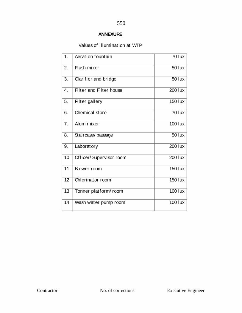
550
Contractor No. of corrections Executive Engineer
ANNEXURE
Values of illumination at WTP
1. Aeration fountain
70 lux
2. Flash mixer
50 lux
3. Clarifier and bridge
50 lux
4. Filter and Filter house
200 lux
5. Filter gallery
150 lux
6. Chemical store
70 lux
7. Alum mixer
100 lux
8. Staircase/passage
50 lux
9. Laboratory
200 lux
10 Officer/Supervisor room
200 lux
11 Blower room
150 lux
12 Chlorinator room
150 lux
13 Tonner platform/room
100 lux
14 Wash water pump room
100 lux
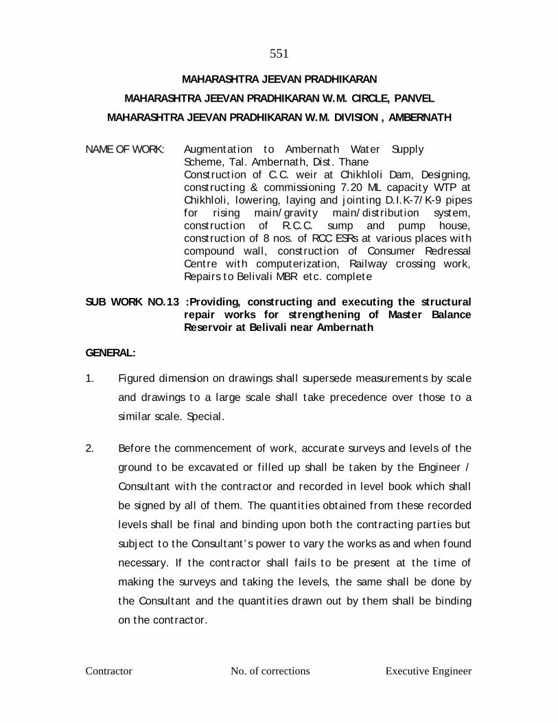
551
Contractor No. of corrections Executive Engineer
MAHARASHTRA JEEVAN PRADHIKARAN
MAHARASHTRA JEEVAN PRADHIKARAN W.M. CIRCLE, PANVEL
MAHARASHTRA JEEVAN PRADHIKARAN W.M. DIVISION , AMBERNATH
NAME OF WORK: Augmentation to Ambernath Water Supply
Scheme, Tal. Ambernath, Dist. Thane Construction of C.C. weir at Chikhloli Dam, Designing,
constructing & commissioning 7.20 ML capacity WTP at Chikhloli, lowering, laying and jointing D.I.K-7/K-9 pipes for rising main/gravity main/distribution system, construction of R.C.C. sump and pump house, construction of 8 nos. of RCC ESRs at various places with compound wall, construction of Consumer Redressal Centre with computerization, Railway crossing work, Repairs to Belivali MBR etc. complete
SUB WORK NO.13 :Providing, constructing and executing the structural
repair works for strengthening of Master Balance Reservoir at Belivali near Ambernath
GENERAL: 1. Figured dimension on drawings shall supersede measurements by scale
and drawings to a large scale shall take precedence over those to a
similar scale. Special.
2. Before the commencement of work, accurate surveys and levels of the
ground to be excavated or filled up shall be taken by the Engineer /
Consultant with the contractor and recorded in level book which shall
be signed by all of them. The quantities obtained from these recorded
levels shall be final and binding upon both the contracting parties but
subject to the Consultant’s power to vary the works as and when found
necessary. If the contractor shall fails to be present at the time of
making the surveys and taking the levels, the same shall be done by
the Consultant and the quantities drawn out by them shall be binding
on the contractor.
552
Contractor No. of corrections Executive Engineer
3. All levels referred to in connection with the works shall be based on a
benchmark as decided by the Engineer / Consultant.
4. The contractor shall provide suitable flat tops and build the same in
cement concrete or brick masonry for temporary bench marks. All the
pegs and sight rails for setting out the work and fixing the necessary
levels required for the execution thereof shall be built in brick masonry
at such places and in such a manner as directed by the Consultant.
5. The whole of the materials used on the work are to be of the best
quality of their respective kinds as specified or described and all the
materials to be used in and about every part of the work may form
time to time be subjected to tests by means of such machines,
instruments and appliances as the Consultant may direct. Samples
whether submitted to govern bulk supplies or required for testing
before use and suitable packages to contain them, shall be provided
free of charge by the contractor. Testing charges for tests, including
their transportation to approved laboratories as directed by
Consultant, handling, etc. shall be borne by the Contractor. Cost of all
routine tests carried out at site shall deemed to be included in the
respective items. All manufactured materials shall unless otherwise
allowed by the Consultant shall bear ISI mark. All other expenditure
required to be incurred for taking samples, conveyance, packaging,
etc. shall be borne by the contractor.
6. Every portion of the work shall be kept clear of accumulations from
time to time and delivered up clean and free from defects of every
kind at the conclusion of the works and the contractor shall provide at
his own cost all such material, implements, scaffolding and labour as
the Consultant may require.

553
Contractor No. of corrections Executive Engineer
7. A rate any one description of work in the Schedule of Quantities is to
be held to include such items of other classes of work as are obviously
necessary for its due completion and for these no separate or specific
charge will be admitted, although they may not be specifically shown
on the drawings or specifications. If due to any alteration of the
schedule item some having in cost or time is likely to result, the
contractor will be called upon to give rebate as will be worked out by
the Consultant.
8. The plea of “Custom Prevailing” will not on any account be permitted
as an excuse for an infringement of any of the Conditions of the
Contract or Specifications.
9. When not specifically mentioned, material shall be procured and work
carried out in accordance with the latest issue of the relevant latest IS
Specifications. The contractor shall comply with all the necessary
safety requirements and precautions as per the relevant latest IS
Specifications.
10. The specifications which follow have been divided into various sections
and reference should be made to relevant common items appearing in
various sections and all that is stated therein should be followed and
general clause or specifications relevant to particular type may prevail
type may prevail as may be expedient.
11. Materials
Cement
L & T/Ambuja/ACC/Birla Gold brand of 43 grade in jute/polyethylene
bags (weighing 50 Kg each) shall be used for all water retaining
structures.
554
Contractor No. of corrections Executive Engineer
Reinforcement
The steel to be used shall be grade Fe.415 as per design. The
contractor shall have to procure the steel from open market. The
steel procured by contractor shall be tested and the contractor shall
produce manufacturer’s test certificate without which it shall not be
accepted. Further the contractor shall arrange to get tested any
samples from steel brought at site by him in laboratory at his cost and
result should be submitted to the Maharashtra Jeevan Pradhikaran. The
reinforcement are to be provided with Fusion Bonded Epoxy paint.
Defective steel brought by contractor shall be rejected and will not be
allowed to be used. Test certificate stating the chemical composition
and characteristics of the product.
At least 3 samples of each diameter should be tested from every 5 ton
or part thereof. Tested lots only will be permitted to be used.
Concrete
The RCC works shall be as per IS 456-2000. Concrete mixer shall be used for preparing concrete. Vibrator shall be used to consolidate concrete while placing in
position.
While concreting, respective samples in form of test cubes shall be
taken by the contractor under Maharashtra Jeevan Pradhikaran
Supervisor and shall be tested under his supervision. Charges of
testing shall be borne by the contractor and will be recovered from
bills payable to him.
Cement shall be Ordinary Portland Cement
The measurement of proportion of cement should normally be on the
basis of weight and whole bages, each undisturbed and sealed 50 Kg
555
Contractor No. of corrections Executive Engineer
bag being considered equivalent to 35 liters (1.2 Cft.) in volume. When
part bag is required, cement shall be taken by weight. Care should be
taken to see that each bag contains full quantity of cement.
Tests
When tests are considered necessary, they shall be carried out as
indicated in IS : 269. The contractor should ensure that the cement is
of sound and required quality before using
Storage
Cement required for use shall be as fresh as possible and stored on
planks raised 15 to 20 cms ( about 6” to 8”) above the floor and
stacked 30 cm ( about 12” ) away from the walls in suitable closed
weather proof buildings at the work site or at the selected approved
site, in such a manner as to prevent deterioration by dampness or
moist atmosphere or instruction of foreign matter..)
Any cement which has deteriorated, baked or which has been damaged
shall not be used. Cement that is condemned shall be immediately
removed from the work site.. Ordinary cement stored for more than 2
months from the date of receipt from the factory shall be subjected to
test and used only if found satisfactory.. Cement shall be kept in a
store under double locking arrangement so that it can be taken our or
fresh stock admitted with the knowledge of supervising staff of the
Department.
WATER Water for mixing cement lime mortar or cement lime concrete shall
not be salty or brackish and shall be clean, reasonably clear and free
from objectionable quantities of silt and tracers of oil, acid injurious
alkali, salts, organic matter and other deterious material which will
either waken the mortar or concrete or cause efflorescence or attack
556
Contractor No. of corrections Executive Engineer
the steel in RCC. Water shall be obtained from sources approved by the
Engineer.
Water for curing cement / lime mortar of concrete
Water for curing mortar or concrete should not be too acidic or too
alkaline. It should a have a pH value ranging between 4.5 to 8.5. It
shall be free of element which significantly affect the hydration
reaction or otherwise interfere with the hardening of mortar of
concrete during curing.Portable water will be generally be found
suitable for curing cement / lime mortar or concrete.
FINE AGGREGATE (SAND) General
All fine aggregate shall conform to IS: 383 ( latest edition) and relevant
portion of IS:515 (latest edition ) directed by the Engineer.
Sand for use in concrete work shall be natural sand shall be clean well
graded, hard, strong durable and gritty particles free from injurious
amounts of dust, clay, kankar, nodules, soft or flaky particles, shale,
alkali, salt organic matter, lam, mica or there deterious substances
and shall be approved by the Engineer. The maximum size of particles
shall be limited to 5 mm ( about 3/16”). Organic impurities and other
detritus substances as laid down in Is :383 ( latest edition). It shall not
contain deterious materials
The fine aggregate for cement mortar for masonry and first coat of
plaster should generally satisfy the following grading.
I.S. Sieve Percentage by Weight Passing Sieve 480 100 240 80 95 120 70 90 60 40 85 30 05 50 15 00 10
The fineness modulus shall not exceed 3.00

557
Contractor No. of corrections Executive Engineer
Gradations
The gradation of materials from any one source shall not vary in
composition beyond there range of value that governs, in selecting
sources of supply. For determining the degree of uniformity,
determination of fitness modulus shall be made upon representative
sample furnished by the contractor from such source as the proposes to
use. Fine aggregate from any one source having variation in fineness
modulus greater than ±0.20 from the average fineness modulus of the
representative samples submitted by the contractor shall be rejected
or may be accepted subject such changes in the proportion aggregate
as the Engineer may direct
Storage
The fine aggregate should be stacked carefully on a clean, hard surface
so that it will not mixed up with deterious foreign materials.
Coarse Aggregate
Coarse aggregate shall consist of crushed or broken stones and be hard,
strong, dense, durable clear or proper gradation and free from skin and
coating likely to prevent proper adhesion of mortar. The aggregate
shall generally be cubical in shape and as far as possible flurry,
elongated pieces shall be avoided. It shall generally comply with the
provision of IS : 383 and IS:515 ( latest edition).
The maximum size of the aggregate may be upto 20 mm and well
graded between the sixes 5 mm to 20 mm in such proportions as to
give maximum density to the concrete. The maximum size should be as
large as possible within the above limit but should not exceed ¼ of the
minimum thickness of the member provided, however, this size
present no difficulty in the case of RCC to surround the reinforcement
thoroughly and fill up the corners of the form work satisfactorily. In

558
Contractor No. of corrections Executive Engineer
the case of general concrete work, a maximum size of 40 mm ( about
1/22’ ) is used and in RCC work a maximum size of 20 mm (about 1 ¼”)
will be found satisfactory, but it should be restricted to 6 mm ( about
¼”) less than the minimum lateral clear distance between bars or 6
mm ( about ¼”) less than the cover, whichever is smaller.
The crushing strength of aggregate will be such as to allow the
concrete in which it is used to build up the specified strength of
concrete.
Approximate range, in grading of coarse aggregate may be as required.
Grading tests shall be in the beginning and at change of surface of
machinery or type of metal. Where required by the Engineer, tests
indicated in IS: 368 and IS: 456 (latest edition) shall be got carried out
in an approved laboratory at the contractor’s cost to show the
acceptability of the material.
Coarse aggregate of a porous nature where absorption of water after
24 hours immersion in water, is more than 5 percent by weight, shall
not be used
Limit of deleterious substance shall not exceed those prescribed in IS :
515 ( latest edition)
Storage
The aggregate of different sixes shall be stored separately and handled
in such manner as to prevent intermixing of different sixes of
aggregate required separately for grading purposes. No foreign matter
shall be allowed to be mixed up with aggregated. If covered with dust
etc. they shall be washed clean before use.
559
Contractor No. of corrections Executive Engineer
MIXING
For all important woks concrete shall be mixed in mechanical mixer at
the site of work. Care shall be taken to see that the mixer an other
accessories are in first to class working condition and maintained so
throughout the construction. Mixing shall be continued till there is
uniform colour is obtained and each individual article of the coarse
aggregate shall show a complete coating of mortar contain in its
proportionate amount of cement. In no case mixing shall be done for
less than 1 ½ minutes.
When hand mixing is permitted by the Engineer it shall be done on a
smooth water tight platform large enough to allow efficient turning
over of the ingredient of concrete before and after adding water.
Mixing platform shall be so arranged that no foreign materials shall be
get mixed water shall flow out.
The cement is required number of bags shall be placed in a uniform
layer on top of the measure quantity of fine aggregate required, also
spread in a layer of uniforms depth in the mixing platform. Dry sand
and cement shall then be mixed thoroughly by turning over to get a
mixture of uniform colour. Enough water then be added gradually
through a rose and the mass turned over till a mortar of required
consistency is obtained. The measured quantity of coarse aggregate
shall then be placed on the mixing platform and wetted and the mortar
added and the entire mss turned and returned until all the particles of
the coarse aggregate are fully covered with mortar and the mixture is
of a uniform colour and required consistency. In hand mixing quantity
of cement shall be increased by 5% above the specified
560
Contractor No. of corrections Executive Engineer
Concrete shall have a consistency such that it will be workable in the
required position and in the case of RCC flow around reinforcing steel
also.
For vibrated concrete slump shall range between 2.5 to 5 cm ( about 1
“ to 2”) For hand tamped concrete, slump shall range between 8 cm to
13 cm ) 3” t 5” according to the type and nature of the concrete item.
The sump shall be the latest permitted by workability. The slump shall
be determined as detailed in relevant IS code provisions and
maintained throughout the concreting operation of a member.
The concrete shall be placed n its final position and rammed, vibrated
and finished within 30 minutes of adding water to cement. Re-
tempering or remixing of partially hardened concrete shall not
permitted. Mixing shall be done only by mechanical mixer
Transporting
The concrete shall be handled from the place of mixing to the final
position as quickly as practicable by methods which will prevent
segregation and loss of ingredients. In no case shall the operation take
more than 15 minutes
Placing
The concrete shall be placed into its final position, compacted and
finished within 30 minutes of mixing the water and before setting
commences. The method of placing shall be such as to avoid
segregation.
Placing shall be done in balanced manner to avoid eccentric loads form
work.

561
Contractor No. of corrections Executive Engineer
As far as practicable the concrete for particular portion shall be done
in one continuous operation. The construction joints when required
shall made only where located on the plans or shown in the pouring
schedule unless otherwise approved by the Engineer. The joint shall be
vertical and shall be made by placing a bulk head at the joint. Before
commencing subsequent concreting, all loose particles, laitance etc.
shall be removed and the surface shall then be covered by thick
cement slurry as part of placement. Care shall be taken during the
placing not to disturb the forms or the reinforcement. Concrete
compacted manually, shall preferably be laid in layers of 51 cm to 20
cm ( about 6“ to 8”) the layers being decided by the time lapse
between the successive layers. The time of laying one layer shall not
exceed 30 minutes. The successive layers shall commence within 30
minutes of laying first layer.
When work is to be resumed on a surface which has hardened, such a
surface shall be roughened and scrubbed with brushes to remove
laitance, care being taken to avoid dislodgment of coarse aggregate,
swept clean thoroughly wetted and covered with 6 mm (about 1”)
thick mortar layer composed of cement ad sand in the same proportion
as the cement and sand in the concrete for securing good bond.
The concrete shall be normally laid in the dry. If the are is under
water, it shall be pumped dry and kept so while placing concrete and
till it sets. Where it is necessary to deposit concrete under water, it
shall be done as per relevant IS code provisions (latest edition). No
extra payment will be made for the special arrangements, plants, etc.
need for the purpose or for the additional 10% cement required to be
added.
562
Contractor No. of corrections Executive Engineer
COMPACTING
The concrete shall be thoroughly compacted during depositing to get a
dense concrete and thoroughly worked into the edges and corners of
the form work as also along its faces and around reinforcement in the
case of RCC by means of suitable tools such as spades and rods to get a
good case finished without honey combing. Concrete shall not
disturbed once it is set. Concrete shall not be disturbed once it is set.
For important or big works where stiffer mix with less slump is
adopted, use of mechanical vibrators is essential. The vibrators shall
have not less than 3600 and preferably about 5000 impulses per minute
and shall be worked at an interval of about 60 cm ( about 2”). It shall
be worked in one place for only such time as will also formation of
dense concrete without sinking and segregation of the coarse
aggregate over vibration shall be avoided.. Vibration shall be added by
spreading and Roding.
Compaction shall necessarily be done by mechanical vibrators. No hand
compaction will be permitted except (I) to supplement vibration near
the edge and faces of forms, to fill the corners completely and to
prevent honey combing or (ii) in members where vibration is not
possible nor desirable in the opinion of the Engineer.
CURING
The contractor shall be initially protected fro damage on account of
impact, undue pressure, excessive head of sub, rains etc. and covered
with wet of stacking Hessians or similar absorbent material soon after
the initial set. After the final set, the concrete shall be kept
continuously wet preferably by pounding water for period of not less
than 14 days from the date of placement . On Sunday, holidays and
days of cessation of work, arrangement shall be made to keep the
concrete continuously watered.
563
Contractor No. of corrections Executive Engineer
Should the contractor fail to water the concrete continuously, the
Engineer may provide labour materials, and equipments required for
watering and recover the costs from the contractor. When atmospheric
temperature exceeds 40°C (104 °F) following precautions should be
taken
1. Stacking aggregate under shade and keeping them moist
2. Using cold water
3. Reduce the time between mixing and placing to the minimum
4. Cooling form work by drinking water
5. Starting curing before concrete dries out
6. Restricting concreting to morning and evenings.
FINISHING
Immediately after the removal of forms and undulations, depressions,
cavities, honey combing broken edges or corners, high spots and other
defects shall be made good and finished with cement mortar 1:2. But
the necessity of such finishing must be exceptional and the total
surface requiring finishing shall not exceed 1% on a average. IF the
initial experience shows that this percentage is exceeded the method
of working itself should be changed to get the required cast finish.
Where the concrete surface is to receive plaster, the surface shall be
roughened immediately after removal of forms and within a day
thereof to secure a bold for the plaster. The rate for concrete is
inclusive of this roughening and finishing. Concrete after finishing shall
be cured for the full period
564
Contractor No. of corrections Executive Engineer
Re-tempering
Concrete shall be mixed only in such quantities as are required for
immediately use and any concrete which has developed initial set shall
not be re-tempered or remixed but shall be destroyed or thrown away.

565
Contractor No. of corrections Executive Engineer
SPECIFICATION AND REPAIR METHODOLOGY FOR REPAIRS TO CONCRETE SLAB OF BELIVALI MBR
Providing of Access and Propping
A scaffolding is to be provided to access the all repair areas. The
arrangement is done using bamboo scaffolding / steel H frame, etc.
The scaffolding to areas such as walls, columns, slabs etc. are to be
done in double layer scaffolding. This can be in Bamboo (not less than
80mm dia) with bamboo spacing not exceeding 1.2 Mtr c/c in all the
three direction. The verticals and horizontals in a scaffolding plane not
to exceed 1.2 Mtr c/c. The two adjacent planes in elevations to be at
1.2 Mtr c/c.
The elevation type scaffolding if done in steel pipes, couplers and / or
H frames then minimum dia meter of pipe to be 40 NB medium class.
Spacing to be 1.8 Mtr c/c maximum between vaetical and 1.2 Mtr c/c
between horizontals. The two adjacent planes in elevations to be at
1.2 Mtr c/c.
In both the types of elevation type scaffolding, the elevation area of
the inner plane of scaffolding (adjacent to structure) will be measured
for payment.
When access of varying height is to be provided to a large plan area
(such as slab soffits in tank) the verticals in bamboo are to be at 1.2
mtr c/c and horizontals in both directions to be at 1.2 Mtr c/c.
The above type of scaffolding when provided in steel pipes, couplers
and / or H frames then the verticals and horizontals in both directions
to be at 1.2 Mtr c/c. In case of H frames the verticals in braced
direction to be 2.4 Mtr c/c maximum (distance between two H frames
braced by two diagonal bracing on either side.)
566
Contractor No. of corrections Executive Engineer
The measurement of such scaffolding is to be on the basis of height of
scaffolding and measured on plant area of scaffolding provided.
Item No.1 – Providing 40mm dia meter adjustable acrow or equivalent
props etc. Providing 40mm dia adjustable acrow or equivalent props on rental basis including fixing and dismantling after use and necessary material required for same etc.
The props shall be provided at a spacing of 1m or 1.5m center to
center as directed by the Engineer-in-Charge. The height of the prop
shall be fixed or adjustable for height of 6.0 meter or upto bottom of
beams. The props shall be made of M.S. or G.I. and of size not less
than 40mm dia. It shall be got approved by Engineer-in-Charge. It shall
be free from any failure joints. The props shall be cross braced at two
levels below the slab. The mode of measurement shall be on numbers
basis.
Mode of payment
The item shall be measured and paid on No. basis.
Item No.2 – Providing scaffolding on rental basis using 40mm dia M.S. pipe
etc. complete Providing scaffolding on rental basis using 40mm dia M.S. pipe at 1.5m
c/c and or H frame bracing or combination of both to arrive a suitable
grid of scaffolding for accessing all the elements of structure from
inside as well as outside including fixing and dismantling after use.
Prop shall be fixed or adjustable for height of 6.0 meter or upto
bottom of beams. The props shall be made of M.S. or G.I. and of size
not less thant 40mm dia. It shall be got approved by Engineer-in-
Charge. It shall be free from any failure joints. The props shall be cross

567
Contractor No. of corrections Executive Engineer
braced at two levels below the slab. The Prop should be preferably
placed away from exposed reinforcement in slab soffit. This will allow
repairs to be done to bars without shifting the props. The Props shall
be as such so as to reach entire soffit.
Mode of payment
The item shall be measured and paid on Sqm. basis.
Item No.3 – Dismantling damaged slab / beams etc.
Dismantling damaged RCC work sagged slab elements, damaged beam
etc. carefully including the reinforcement stacking the serviceable
material and debris separately and disposing off the same as directed
by Engineer-in-Charge. Mark beam position on slab for support to
person. Use of electrically operated or pneumatically operated chisel
to loosen all the concrete in damaged panels and free the
reinforcement. Place the props at 1 meter center to center below
beams before dismantling. Portion of columns needs to be checked and
chipped for hollowness.
Mode of payment
The item shall be measured and paid on Cum. basis.
Item No. 4 – Chipping of existing plaster
Chipping of loose concrete from beams, columns, soffits, walls etc.
and other structural elements to expose sound concrete beneath using
light chisel and hammer electrically operated chisel may be used.
Removing of rust from the exposed reinforcement and also preparing
the concrete surface including all material, labour, tools scaffolding
etc. complete.
a) The loose concrete behind reinforcement if any should be carefully
removed. Corroded reinforcement should not be bent using chisel in

568
Contractor No. of corrections Executive Engineer
order to create access. Only loose concrete should be taken out.
This can be checked by lightly sounding the hammer over chipped
area to ascertain any hollow sound on substrate.
b) Removal of corrosion scales on corroded reinforcement bars should
be done manually using sharp tools such as chisel to scrape rust
scales from the surface. Thereafter using wire brushes to clean the
surface of rebars. Since brush would not be able to access behind
the bars use emery paper to clean exposed surface as well as areas
with difficult access. Rotary wire brushed, shaft type rotary wire
brushed can be used in place of hand held brushes, exposed
concreted surface is also to be cleaned with wire brush / rotary
wire brush to remove all the loose material dust, dirt oil etc.
complete.
c) For areas requiring only painting, wire brush and / or rotary wire
brush grinding to be done to remove all the loose material and
prepare the surface.
Portion of columns which may be sounding hollow may also need to be
checked and chipped off. Check and chip of lose sounding / honey
combed construction joints.
Mode of payment
The item shall be measured and paid Per Sq. mt. area of chipping of
loose concrete from structural elements.
Item No.5 – Overall surface preparation of the concrete surface etc. complete.
Cleaning concrete surface (wherever there is no plaster in original
structure) with wire brush to receive further treatment including
necessary scaffolding etc. The surface preparation is of prime
importance for the repairs. Unless the corrosion scales are completely
569
Contractor No. of corrections Executive Engineer
removed, no further repairs are to be carried out. Expose concrete
surface is also to be cleaned with wire brush / rotary wire brush to
remove all the loose material, dust, dirt, oil etc. finally use
compressed air to clean the surface. Clean all the exposed
reinforcement with wire brushed etc. to remove all loose cement
slurry, dust, dirt and prepare it to receive further protective
treatment.
Mode of payment
The item shall be measured and paid on Per Sqmt. Area
Item No.6 – Providing Steel Reinforcement
Providing and fixing in position steel reinforcement of various dia
meter as required at site form of mild steel confirming to IS:456:1964
and lapping, welding, anchoring suitable to old reinforcement including
scaffolding cost of binding wire etc. complete.
1. Wherever the reinforcement is reduced by more 20% of the
original reinforcement, extra main steel is to be provided by welding a suitable dia to existing steel or lapping it suitably (lap-50 times the bar dia). While doing this it may be necessary to take anchorage in sound concrete in case length beyond damaged portion is not adequate to provide lap and welding is not feasible. In such cases drill a slightly oversize (4mm more in dia) hole adjacent to existing main reinforcement to a depth of 150 mm dna anchor new reinforcement using epoxy grout made with 1 Kg Resin KP 350 0.5 Kg hardner HP 350 3 Kg Fine Sillca filler (smaller than 300 microns)
2. For anchoring the main vertical reinforcement in column to be strengthened excavation must done up to the top of footing and anchorage should be taken into concrete. This is done again by drilling holes of higher dia and anchoring with exoxy grout as above. After column strengthening, the soil excavated must be

570
Contractor No. of corrections Executive Engineer
filled back. Dewatering if necessary shall be arranged by the contractor. Item of excavation and back filling will not be paid separately.
3. Apart from the main reinforcement it is necessary to provide
lateral reinforcement such as links to column and stirrups to beams. Additional stirrups to column can be provided by making all round groove of 10mm x 25mm deep at 150mm c/c along the columns height on the outer surface of concrete (in portion where sme portion of sound concrete exists) and providing 2U shaped stirrups of 8mm dia with lap of 40 dia. The new stirrups are to be tied to new and old main steel using binding sire of 20 G.
4. New and old reinforcement shall be welded together.
Old reinforcement after cleaning shall be checked and then only shall be applied with rust removing primer. Additional reinforcement of 10mm and 12mm shall be used for slab and beams where existing reinforcement is exposed.
5. New reinforcement can be clamped on soffit of damaged
concrete slabs or shell elements and anchored into supporting beams. New steel reinforcement shall be welded to existing reinforcement. It shall be in same plane as existing reinforcement.
Mode of payment
The item shall be measured and paid on Per M.T. basis.
Item No.7 – Providing and fixing wire mesh to improve the confinement of reinforcement.
1. Providing and fixing wire mesh as per specification in the form
of one layer of 50 x 50 mm x 12 SWG. GI weld wire mesh and
one layer ½” x ½” x 26 Gauge. GI hexagonal mesh to columns.
beams slabs and other structural element and anchoring to the
element with binding wire nails including all material, labour,
scaffolding.
2. To remove the confinement to deteriorated core concrete GI
weld wire mesh 2” x 2” x 12 gauge along with two layer of G.I.
571
Contractor No. of corrections Executive Engineer
hexagonal mesh of ½” x ½” x 26 gauge is to be clamped on all
sides of beams and columns as per details. The extra main steel
can be lapped to main bottom steel or anchored into supporting
columns / main beams with epoxy grouted holed as mentioned
above. From practical consideration the mesh is sot be made
ready for final fixing and is to be clamped after application of
bond coated.
3. New reinforcement can be clamped on soffit of damaged
concrete slabs and anchored into supporting beams or at end of
slab by making ‘L’ shape bend.
4. The mesh is got to be clamped on to concrete surface by means
of GI plumber and binding wire.
Mode of payment
The item shall be measured and paid on Per Sq. Mt. basis.
Item No.8 – Providing and applying two coats of rust remover primer feovrt etc. complete
Before applying rust remover primer, remove loosely held rust
using a hand wire brush gently but leave behind the layer of rust
directly attached to the under laying steel. Ensure removal of oil
or greasy residues if any, with strong detergent and wash with
clean water. Allow it to dia. Apply the feovert using a brush or
spray. If there is heavy rust present, apply minimum two coats as
directed by Engineer-in-Charge. Allow it to cure for 6 to 8 hours
or as directed. It shall be applied by brush to all accessible parts
of exposed cleaned reinforcement. The product should be got
tested by testing laboratory before put in use.
572
Contractor No. of corrections Executive Engineer
Mode of payment
The item shall be measured and paid on Per Liter basis.
Item No.9 – Providing and applying corrosion inhibitor EPCO KP 100 etc.
complete.
Providing and applying corrosion inhibitor EPCO KP-100 to the entire
face to be repaired and coating the exposed old as well as new
reinforcement (if new ordinary steel without fusion bonded epoxy is
used) by brush including all materials labour, tools, scaffolding etc.
a) It has been observed that various structural elements are
showing sever corrosion on account of leakage of water,
exposure to attacks of atmosphere vapours, fumes and gases.
Carbonation depth is also substantial. As a result the passive
corrosion protection offered by concrete surrounding the
reinforcement is not longer available in damaged areas. The
corrosion activity beyond the portion where concrete has spalled
or chipped of cannot be ascertained. Usually there is lower
degree of corrosion in these areas.
b) In order to address the inhibition of corrosion in reinforcement
MIGRATING CORROSION INHIBITORS is required to implemented.
These are new types of corrosion inhibitors, which due to their
very low vapour pressure and high affinity towards metallic
surface migrate through concrete and form a monocular
protective film on steel surface. The active ions remains in the
vicinity of the reinforcement and go on replacing the ions which
might get disloged from the present film. Thus the protective
film on parent steel surface is always retained. This film is
formed on cathodic as well as anodic sites and completely
controls the process of corrosion. The active ions also work
573
Contractor No. of corrections Executive Engineer
effectively on corroded reinforcement in a chloride infiltrated
concrete. In the present situation such product is essential as
pretreatment to corroded as well as new reinforcement in a
chloride infiltrated concrete. In the present situation such
product is essential as pretreatment to corroded as well as new
reinforcement, as overall surface application on the areas to be
repaired.
c) Apply one coat of EPCO-KP-100 Migrating corrosion inhibitor on
concrete area to be repaired, old as well as new reinforcement.
The application should be done after all the rust removal and
provision of new reinforcement is completed. Application should
be done by brush and coverage, should be 4 Sqmt. Or repair
area per literature of the product. Measurement of this item will
be on the basis of sq. mt. area repaired.
Mode of payment
The item shall be measured and paid on Per Sqmt. basis.
Item No. 10 – Providing and applying two coats of anticorrosive reber
protection system IP Net RB etc. complete.
Providing and applying 2 coats anticorrosive reber protection
system IP Net RB on old reinforcement as per manufacture
specification with wire brush with interval of 24 hours including
all labour, material, tools, scaffolding etc. complete.
Apply epoxy phenolic based IP Net RB or equivalent reinforcement
protection coating after 15 minutes of application of MCI. The
coating applied should be flexible and should exhibit elongation
properties. Two coats of such anticorrosive system are to be
applied with a gap of 24 hours. Spray sharp silica sand on the
second coat of bar protection coating to facilitate better bonding.
Wherever lapping of new reinforcement is to be done, pre treat

574
Contractor No. of corrections Executive Engineer
the new reinforcement with IP Net RB in two coats as mentioned
above.
Mode of payment
The item shall be measured and paid on Sqmt. basis.
Item No. 11 – Providing and applying two coats of anticorrosive reber protection system IP Net RB etc. complete.
Providing and applying 2 coats anticorrosive reber protection system IP
Net RB on old reinforcement as per manufacture specification with
wire brush with interval of 24 hours including all labour, material,
tools, scaffolding etc. complete.
Apply epoxy phenolic based IP Net RB or equivalent reinforcement
protection coating after 15 minutes of application of MCI. The coating
applied should be flexible and should exhibit elongation properties.
Two coats of such anticorrosive system are to be applied with a gap of
24 hours. Spray sharp silica sand on the second coat of bar protection
coating to facilitate better bonding. Wherever lapping of new
reinforcement is to be done, pre treat the new reinforcement with IP
Net RB in two coats as mentioned above.
Mode of payment
The item shall be measured and paid on the basis of quantity of IP
NET-RB consumed (Liter)
Item No.12 –Providing and applying bonding agent between old and new concrete EL MONOBOND etc. complete.
575
Contractor No. of corrections Executive Engineer
Providing and applying one coat of epoxy latex based polymer bond
coat EL Monobond before the repairs with polymer modified mortar
including all materials, labour tools scaffolding etc. complete.
Bonding Coat
1. Bonding coat for the repairs system is based on Epoxy latex EL-
MONOBOBD. The bonding slurry is to be prepared in following
mix Proportion.
2. 1 Part by weight EL-MONOBOND Part-A
One part by weight EL MONOBOND Part-B
One part by weight water
2 Parts by weight cement
This is to be mixed in small container and stirred continuously for 5
minutes to get a homogeneous slurry. Only small quantity is to be
mixed at a time. This decided by the area that be cover with repair
mortar which is to be applied subsequently. Mix all the ingredients
thoroughly and apply by Brush. Bonding slurry should be applied within
15 minutes of mixing. Prewet the surface before application of bonding
slurry wait for 15 minutes and then apply the bonding slurry by stiff
nylon brush evenly on the entire repair area including the
reinforcement, consumption is 2 Sqmt per liter of prepared bond coat.
This is a epoxy based bonding agent which ensure perfect bond
between old and repair concrete. Application is by brush only for non
structural grade, bonding use polymer bond coat prepared with one
part acrylic based. Po9lymer latex monobond + 1 part water + 1.5 part
cement mix all ingredients thoroughly and apply by brush.
Consumption on rough repair surface in 0.75 Kg ready bonding slurry
per Sqmt of repair area.
576
Contractor No. of corrections Executive Engineer
Mode of payment
The item shall be measured and paid on Sqmt. basis.
Item No.13 – Repairing the damaged portion of RCC structure with polymer
modified morter etc. complete.
Providing and applying polymer modified mortar prepared as per
detailed mix to column, beams, soffits, slabs, walls etc. And other
element as directed in varying thickness with trowel and finish smooth
in layers not exceeding 20mmk at a time after application including
scaffolding, curing etc. Cement: Sand ratio 1:3 (clean river sand) with
15% monobond W/C not to exceed 0.45. Preparing damaged portion
with repairing mortar.
a. Columns, Beams and Slab Soffits etc. with polymer modified
repair mortar of following specifications.
i. Repair morter 1 Cum. Shall have following proportion 500 Kg
cement OPC 43 grade or blended cement, 1500 Kg. sand - well
graded river sand 4.76 mm down size, 75 Kg Polymer latex
additive monobond with 120 grams of polypropylene fibers KR /
ELB per Bag of cement. 200 to 225 Kg water.
ii. The above mix should be re-proportioned for equivalent to ½
bag of cement and should be mixed in a steel tray.
iii. The dry ingredients are to be mixed to make a dry mix.
MONOBOND is to be added to 80% of the mixing water and then
this should be added to dry mix. Mixing should continue for 5
minutes. Then balance mixing water is to be added. Mortar thus
prepared should be immediately covered with plastic sheet to
avoid loss of consistency. This mortar should be used within 30
minutes.

577
Contractor No. of corrections Executive Engineer
iv. This will applied by trowel and finished smooth without excessive
finish. In one application 20 to 25 mm of thickness is to be built up.
Subsequent layers to be done with one bond coat of cement slurry.
v The thickness of repair may be variable depending upon the
extent of damage.
vi Cover the element with burlap and cure by spraying periodically
with water for 2 days and allow to dry for next 10 days.
vii Testing of Mortar : For every 5 Cum repair mortar test should be
conducted randomly by taking the samples of site prepared
mortar and casting 70mm mortar cubes and testing 3 days and
28 days compressive strength. The requirement of air cured
sample are as follows. 3 days strength : Average strength of 3
Cubes = 125 Kg/ Sq.cm., 28 days strength : Average of 3 Cubes =
300 Kg/Sqcm
Mode of payment
The item shall be measured and paid on Sqm. basis.
Item No. 14 – Applying in two coats fiber reinforcement repair morter entire soffits of slab etc. complete.
a) The repairs are to carried out using site made repair mortar
prepared as per detailed mix given below
Cement : Sand B 1:2 (River sand) by weight with one pack 3.3
Kg.
Super screed-P : (Fiber reinforced, micro silica and super
plasticizer blended additive) per bag of cement with W/ Cement
ration not to exceed 0.45. This prepared mix get a cohesive
uniformly blended repair mortar.

578
Contractor No. of corrections Executive Engineer
b) This will be by trowel and finished smooth without excessive
finishing. In one application 20mm of thickness is to be built up.
Subsequent layers to be done with one coat of cement slurry.
c) Cover the element with burlap and cure by spraying periodically
with water for 10 days to prevent initial drying shrinkage.
d) Testing of Mortar
For every 5 meters three repair morter tests should be
conducted randomly by taking the samples of site prepared
mortar and casting 70mm morter cubes and testing 3 days and
28 days compressive strengths. The requirement of wet / dry
cured samples are as follows.
3 days strength Av. Strength of 3 cubes = 150 Kg /
Sqcm
28 days strength Av. 3 cubes = 350 Kg/Sqcm
Mode of payment
The item shall be measured and paid on Sqmt. basis.
Item No.15 & 16 – Drilling Holes by Injection Grouting Treatment of Construction Joints from Inside as well as Outside
a) Groove cutting and cleaning the joints
Since the leakage are predominantly through the joints, the
repair will be concentrated in this area. The joints are required
to be opened out and treated for subsequent work. The existing
joints are to be chiseled out to a depth of 25mm and width
50mm in the form of a ‘V’ groove.
b) General Cleaning
In these locations, if there is any algae formation and leakage
spots cannot be identified unless surface cleaning is completed.
579
Contractor No. of corrections Executive Engineer
This will involve removal of all the loose material, algae,
embedded material such as loose bars, plywood, binding wire
etc.
c) Sealing the Groove
In grooves epoxy latex bonding agent is applied and immediately
polymer modified mortar made with 1:3 cement sand and 15%
polymer latex MONOBOND is used to seal groove. While repairing
also fix PVC nozzles for injection grouting using polymer
modified cement grout. Wherever the injection are also set in
the same material. The measurement of the treatment of
construction joints will be under respective items of bond coat,
polymer modified mortar and injection grouting.
Treatment for Honeycombed Areas and Concrete Core
Strengthening
1. In case it is noticed that the beams, columns or slab element
have honeycombing inside after removal of loose concrete
material, it is necessary to inject polymer modified cement
grout in the honeycombed area. Same methodology is used to
inject construction joints.
First of all a hole of about 16mm dia is to be drilled into the
honeycombed area, construction joints and into core of element
to be strengthened., the depth of the drilled hole should be
about 200mm (in case of slabs, walls and domes the drilled hole
depth to be 60% of the element thickness). In case of slab a grid
margin of holes @ 500mm c/c should be done. In honey combed
area spacing has to be reduced to about 150mm c/c use
compressed air to clean the hole as well as honey combed area
to remove dust and dirt. Then a 12mm dia flexible PVC injection
580
Contractor No. of corrections Executive Engineer
nipple is to be fixed into the hole. Spacing of the hole should be
about 500mm seal the surface round the nipple with polymer.
Seal the surface around nipple with polymer modified mortar as
per mix in Specification portion (I) after application of bond
coat as per specification item (H). This would ensure that the
injected grout does not leak from the gaps.
2. In case of the honeycombed areas fix nipples and repair the
honeycombed patch with polymer modified mortar on polymer
bond coat as per specification part (I) and (H) respectively.
Payment for Bond coat and polymer modified mortar used for
sealing honeycombed and nozzles will be paid separately as per
respective items.
3. The preparation done above should be allowed to cure for 24
hours.
4. Prepare the polymer modified cementations grout with following
mix proportion.
50 Kg cement (1 bag)
2.5 Kg Polymer latex MONOBOND
0.5 Kg Super plasticizer SUPERCON – 100
0.50 Kg grouting admixture EPCO-5040
20 to 25 Liters water
The above mix should be mixed in a container and stirred with
high speed stirrer for 5 minutes and should be used within 30
minutes.
5. Use 140 PSI grade Killic Nixon make injection grout pump.
6. Injection should start from bottom most nipple or from one end
to another in case of horizontal crack and proceed progressively
to subsequent nipples. Once the grout comes out of upper next
nipple being injected should be closed and gun should be
connected to next nipple. Some time if the path is not continues
there may be resistance to injection (no grout flow in spite of
581
Contractor No. of corrections Executive Engineer
maintaining the maximum pressure for 5 minutes). In such a
situation proceed to the next nipple.
7. After completing the injection allow in to cure for 24 hours.
Hence remove the nozzles and seal the holes with polymer
modified mortar.
Mode of payment
The item No.15 shall be measured and paid on Per Numbers of holes.
The item No.16 shall be measured and paid on Per No. of Bag.
Item No.17 & 18 – Drilling Holes and providing epoxy resins for injection and grouting etc. complete.
1. For cracks caused by structural distress such as shear cracks,
flexural cracks, tensile cracks should be injected with low
viscosity epoxy resin. The properties of injection resin desired
are as follows :
2. First of all used chisel and hammer to widen the cracks on the
surface to about 15mm wide and 15 mm deep. Then holes of
about 13mm dia are to be drilled along the cracks. The depth of
the drilled hole should be about 200 mm (incase of slabs, walls
and domes the drilled hole depth to be 60% of the element
thickness.) Use compressed air to clean the hole, as well as
cracks to remove dust and dirt. Then a 12mm dia special
injection nipple ROHIB is to be fixed into the hole. Spacing of
the holes should be about 300 mm.
Seal the surface around the nipple with epoxy putty EPCO-1010.
Also seal the surface of the crack with epoxy putty. This would
ensure that the injected grout does not leak from the gap and
from crack surface.
582
Contractor No. of corrections Executive Engineer
3. The preparation done as above should be allowed to cure
for 24 hours.
4. Prepare the injection resin Low viscosity resin monopol by
mixing resin and hardener in proportion recommended by the
manufacturer. Only small quantities are to be mixed at a time.
Use stirrer or a steel rod to site the mixture thoroughly.
5. The above mix should be done in a container and mixed
thoroughly for 5 minutes.
6. Use special injection guns with pressure gauge and valves for
controlling flow of compressed air and resin. Pressure for
injection should be of 2 to 3 Kg. / Sqcm. Next day repeat the
injection procedure with low viscosity version KP250/HP250 S/V
using 5-7 Kg/Sqcm pressure.
7. Injection should start from bottom most nipple (or from one end
to another in case of horizontal crack) and proceed progressively
to subsequent nipple. Once the resin comes out of the upper or
next nipple the nipple being injected should be closed and gun
should be connected to next nipple. Sometimes if the path is not
continues there may be resistance to injection (no resin flows in
spite of maintaining the maximum pressure for 5 minutes). In
such a situation proceed to the next nipple.
8. After completing the injection allow it to cure for 24 hours.
Then remove the nozzles and seal the holes with epoxy putty.
Payment for this item will be done on the basis of injection resin
consumed.
Mode of payment
The item No.17 shall be measured and paid on Per Numbers of holes.
The item No.18 shall be measured and paid on Per Kg. basis.
583
Contractor No. of corrections Executive Engineer
Item No.19 – Providing and applying protective coating using MONOPOL 456 etc. complete.
Providing and applying protective coating on acrylic base on structural
elements such as columns, beams, walls slabs, staircases etc. in 3
coats with desired colour as per detailed specification using MONOPOL-
456 including all material, labour, scaffolding, tools etc. complete.
Overall Protective Coating
1. Overall protection of concrete surface : It is absolutely
necessary to protect not only the damaged concrete elements
but also those which are in good conditions now but are likely to
get damaged over a period of time. Overall protection of top
surface of tank is absolutely necessary to prevent leakages, but
also reinforcement in slab and beams from getting corrugated.
For this following minimum comprehensive treatment is
suggested.
2. Clan the concrete surface with wire brush and remove all dirt,
dust oil stains etc. complete. Use compressed air to blow loose
dust dirt and cement particles, The surface should also be
completely dry. The coating should be done in areas where
specifically direct contact with vapour, moisture, gases or
chemical wash is expected. In area where direct contact with
acids is likely this coating should not be applied. In such areas a
special high performance coating system should be applied.
Give a barrier against carbonation and excellent protection
against weathering action and corrosion as well as protection of
standing water apply these coats of Allphali Acrylic resin based
protective coating MONOPOL 456.

584
Contractor No. of corrections Executive Engineer
3. Apply primer coat of acrylic resin coating MONOPOL 456 these
coating would give a barrier against carbonation and fairly good
chemical resistance. They should also allow breathing of
concrete and prevent moisture ingress. Application should be
done by spray or brush. Coverage 5 Sqmt / Lit.
4. Application of middle and top coat of MONOPOL-456. The gap
between 2 coats should be 24 hours. Before application of
subsequent coat if there is any dust accumulation on the surface
it should be removed.
5. Coverage 4.5 Sqmt / Coat. Application should be done by spray
or brush. The dry film thickness of three coats should be
minimum 150 microns.
Mode of payment
The item shall be measured and paid on Sqmt. basis.
Item No.20 – Providing and casting in situ cement concrete of
trap/granite/quartzite/gneiss metal for RCC work…etc complete
a) The specification contained in the Standard Specification
Volume II Published by Public Works and Housing Department,
Government of Maharashtra, Chapter Bd-F1 to F-2 and Bd-E1
shall apply.
b) This work shall be done in accordance with IS:456:2000 (revised)
c) Proper curing be done for 21 days.
Requirement of Materials
Cement
L & T/Ambuja/ACC/Birla Gold brand of 43 grade in jute/polyethylene
bags (weighing 50 Kg each) shall be used for all water retaining
structures.
585
Contractor No. of corrections Executive Engineer
Reinforcement
The steel to be used shall be grade Fe.415 as per design. The
contractor shall have to procure the steel from open market. The
steel procured by contractor shall be tested and the contractor shall
produce manufacturer’s test certificate without which it shall not be
accepted. Further the contractor shall arrange to get tested any
samples from steel brought at site by him in laboratory at his cost and
result should be submitted to the Maharashtra Jeevan Pradhikaran. The
reinforcement are to be provided with Fusion Bonded Epoxy paint.
Defective steel brought by contractor shall be rejected and will not be
allowed to be used. Test certificate stating the chemical composition
and characteristics of the product.
At least 3 samples of each diameter should be tested from every 5 ton
or part thereof. Tested lots only will be permitted to be used.
Concrete
The RCC works shall be as per IS 456-2000. Concrete mixer shall be used for preparing concrete. Vibrator shall be used to consolidate concrete while placing in
position.
While concreting, respective samples in form of test cubes shall be
taken by the contractor under Maharashtra Jeevan Pradhikaran
Supervisor and shall be tested under his supervision. Charges of
testing shall be borne by the contractor and will be recovered from
bills payable to him.
Cement shall be Ordinary Portland Cement
The measurement of proportion of cement should normally be on the
basis of weight and whole bages, each undisturbed and sealed 50 Kg
bag being considered equivalent to 35 liters (1.2 Cft.) in volume. When
586
Contractor No. of corrections Executive Engineer
part bag is required, cement shall be taken by weight. Care should be
taken to see that each bag contains full quantity of cement.
Tests
When tests are considered necessary, they shall be carried out as
indicated in IS : 269. The contractor should ensure that the cement is
of sound and required quality before using
Storage
Cement required for use shall be as fresh as possible and stored on
planks raised 15 to 20 cms ( about 6” to 8”) above the floor and
stacked 30 cm ( about 12” ) away from the walls in suitable closed
weather proof buildings at the work site or at the selected approved
site, in such a manner as to prevent deterioration by dampness or
moist atmosphere or instruction of foreign matter..)
Any cement which has deteriorated, baked or which has been damaged
shall not be used. Cement that is condemned shall be immediately
removed from the work site.. Ordinary cement stored for more than 2
months from the date of receipt from the factory shall be subjected to
test and used only if found satisfactory.. Cement shall be kept in a
store under double locking arrangement so that it can be taken our or
fresh stock admitted with the knowledge of supervising staff of the
Department.
WATER
Water for mixing cement lime mortar or cement lime concrete shall
not be salty or brackish and shall be clean, reasonably clear and free
from objectionable quantities of silt and tracers of oil, acid injurious
alkali, salts, organic matter and other deterious material which will
either waken the mortar or concrete or cause efflorescence or attack
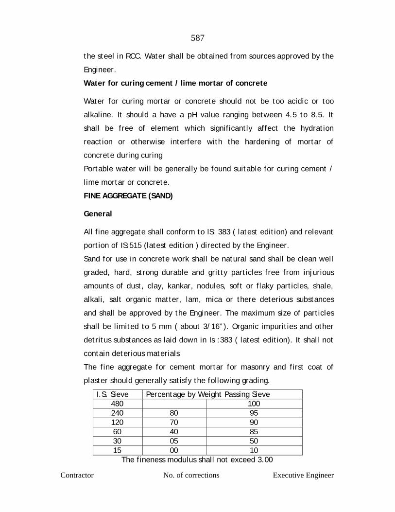
587
Contractor No. of corrections Executive Engineer
the steel in RCC. Water shall be obtained from sources approved by the
Engineer.
Water for curing cement / lime mortar of concrete
Water for curing mortar or concrete should not be too acidic or too
alkaline. It should a have a pH value ranging between 4.5 to 8.5. It
shall be free of element which significantly affect the hydration
reaction or otherwise interfere with the hardening of mortar of
concrete during curing
Portable water will be generally be found suitable for curing cement /
lime mortar or concrete.
FINE AGGREGATE (SAND) General
All fine aggregate shall conform to IS: 383 ( latest edition) and relevant
portion of IS:515 (latest edition ) directed by the Engineer.
Sand for use in concrete work shall be natural sand shall be clean well
graded, hard, strong durable and gritty particles free from injurious
amounts of dust, clay, kankar, nodules, soft or flaky particles, shale,
alkali, salt organic matter, lam, mica or there deterious substances
and shall be approved by the Engineer. The maximum size of particles
shall be limited to 5 mm ( about 3/16”). Organic impurities and other
detritus substances as laid down in Is :383 ( latest edition). It shall not
contain deterious materials
The fine aggregate for cement mortar for masonry and first coat of
plaster should generally satisfy the following grading.
I.S. Sieve Percentage by Weight Passing Sieve 480 100 240 80 95 120 70 90 60 40 85 30 05 50 15 00 10
The fineness modulus shall not exceed 3.00
588
Contractor No. of corrections Executive Engineer
Gradations
The gradation of materials from any one source shall not vary in
composition beyond there range of value that governs, in selecting
sources of supply. For determining the degree of uniformity,
determination of fitness modulus shall be made upon representative
sample furnished by the contractor from such source as the proposes to
use. Fine aggregate from any one source having variation in fineness
modulus greater than ±0.20 from the average fineness modulus of the
representative samples submitted by the contractor shall be rejected
or may be accepted subject such changes in the proportion aggregate
as the Engineer may direct
Storage
The fine aggregate should be stacked carefully on a clean, hard surface
so that it will not mixed up with deterious foreign materials.
Coarse Aggregate
Coarse aggregate shall consist of crushed or broken stones and be hard,
strong, dense, durable clear or proper gradation and free from skin and
coating likely to prevent proper adhesion of mortar. The aggregate
shall generally be cubical in shape and as far as possible flurry,
elongated pieces shall be avoided. It shall generally comply with the
provision of IS : 383 and IS:515 ( latest edition).
The maximum size of the aggregate may be upto 80 mm ( about 3”)
and well graded between the sixes 5 mm to 80 mm ( about 3/16” to
3”) in such proportions as to give maximum density to the concrete.
The maximum size should be as large as possible within the above limit
but should not exceed ¼ of the minimum thickness of the member
provided, however, this size present no difficulty in the case of RCC to
surround the reinforcement thoroughly and fill up the corners of the
589
Contractor No. of corrections Executive Engineer
form work satisfactorily. In the case of general concrete work, a
maximum size of 40 mm ( about 1/22’ ) is used and in RCC work a
maximum size of 20 mm (about 1 ¼”) will be found satisfactory, but it
should be restricted to 6 mm ( about ¼”) less than the minimum
lateral clear distance between bars or 6 mm ( about ¼”) less than the
cover, whichever is smaller.
The crushing strength of aggregate will be such as to allow the
concrete in which it is used to build up the specified strength of
concrete.
Approximate range, in grading of coarse aggregate may be as required.
Grading tests shall be in the beginning and at change of surface of
machinery or type of metal. Where required by the Engineer, tests
indicated in IS: 368 and IS: 456 (latest edition) shall be got carried out
in an approved laboratory at the contractor’s cost to show the
acceptability of the material.
Coarse aggregate of a porous nature where absorption of water after
24 hours immersion in water, is more than 5 percent by weight, shall
not be used
Limit of deleterious substance shall not exceed those prescribed in IS :
515 ( latest edition)
Storage
The aggregate of different sixes shall be stored separately and handled
in such manner as to prevent intermixing of different sixes of
aggregate required separately for grading purposes. No foreign matter
shall be allowed to be mixed up with aggregated. If covered with dust
etc. they shall be washed clean before use.
590
Contractor No. of corrections Executive Engineer
MIXING
For all important woks concrete shall be mixed in mechanical mixer at
the site of work. Care shall be taken to see that the mixer an other
accessories are in first to class working condition and maintained so
throughout the construction. Mixing shall be continued till there is
uniform colour is obtained and each individual article of the coarse
aggregate shall show a complete coating of mortar contain in its
proportionate amount of cement. In no case mixing shall be done for
less than 1 ½ minutes.
When hand mixing is permitted by the Engineer it shall be done on a
smooth water tight platform large enough to allow efficient turning
over of the ingredient of concrete before and after adding water.
Mixing platform shall be so arranged that no foreign materials shall be
get mixed water shall flow out.
The cement is required number of bags shall be placed in a uniform
layer on top of the measure quantity of fine aggregate required, also
spread in a layer of uniforms depth in the mixing platform. Dry sand
and cement shall then be mixed thoroughly by turning over to get a
mixture of uniform colour. Enough water then be added gradually
through a rose and the mass turned over till a mortar of required
consistency is obtained. The measured quantity of coarse aggregate
shall then be placed on the mixing platform and wetted and the mortar
added and the entire mss turned and returned until all the particles of
the coarse aggregate are fully covered with mortar and the mixture is
of a uniform colour and required consistency. In hand mixing quantity
of cement shall be increased by 5% above the specified

591
Contractor No. of corrections Executive Engineer
Concrete shall have a consistency such that it will be workable in the
required position and in the case of RCC flow around reinforcing steel
also.
For vibrated concrete slump shall range between 2.5 to 5 cm ( about 1
“ to 2”) For hand tamped concrete, slump shall range between 8 cm to
13 cm ) 3” t 5” according to the type and nature of the concrete item.
The sump shall be the latest permitted by workability. The slump shall
be determined as detailed in relevant IS code provisions and
maintained throughout the concreting operation of a member.
The concrete shall be placed n its final position and rammed, vibrated
and finished within 30 minutes of adding water to cement. Re-
tempering or remixing of partially hardened concrete shall not
permitted. Mixing shall be done only by mechanical mixer
Transporting
The concrete shall be handled from the place of mixing to the final
position as quickly as practicable by methods which will prevent
segregation and loss of ingredients. In no case shall the operation take
more than 15 minutes
Placing
The concrete shall be placed into its final position, compacted and
finished within 30 minutes of mixing the water and before setting
commences. The method of placing shall be such as to avoid
segregation.
Placing shall be done in balanced manner to avoid eccentric loads form
work.
592
Contractor No. of corrections Executive Engineer
As far as practicable the concrete for particular portion shall be done
in one continuous operation. The construction joints when required
shall made only where located on the plans or shown in the pouring
schedule unless otherwise approved by the Engineer. The joint shall be
vertical and shall be made by placing a bulk head at the joint. Before
commencing subsequent concreting, all loose particles, laitance etc.
shall be removed and the surface shall then be covered by thick
cement slurry as part of placement. Care shall be taken during the
placing not to disturb the forms or the reinforcement. Concrete
compacted manually, shall preferably be laid in layers of 51 cm to 20
cm ( about 6“ to 8”) the layers being decided by the time lapse
between the successive layers. The time of laying one layer shall not
exceed 30 minutes. The successive layers shall commence within 30
minutes of laying first layer.
When work is to be resumed on a surface which has hardened, such a
surface shall be roughened and scrubbed with brushes to remove
laitance, care being taken to avoid dislodgment of coarse aggregate,
swept clean thoroughly wetted and covered with 6 mm (about 1”)
thick mortar layer composed of cement ad sand in the same proportion
as the cement and sand in the concrete for securing good bond.
The concrete shall be normally laid in the dry. If the are is under
water, it shall be pumped dry and kept so while placing concrete and
till it sets. Where it is necessary to deposit concrete under water, it
shall be done as per relevant IS code provisions (latest edition). No
extra payment will be made for the special arrangements, plants, etc.
need for the purpose or for the additional 10% cement required to be
added.
593
Contractor No. of corrections Executive Engineer
COMPACTING
The concrete shall be thoroughly compacted during depositing to get a
dense concrete and thoroughly worked into the edges and corners of
the form work as also along its faces and around reinforcement in the
case of RCC by means of suitable tools such as spades and rods to get a
good case finished without honey combing. Concrete shall not
disturbed once it is set. Concrete shall not be disturbed once it is set.
For important or big works where stiffer mix with less slump is
adopted, use of mechanical vibrators is essential. The vibrators shall
have not less than 3600 and preferably about 5000 impulses per minute
and shall be worked at an interval of about 60 cm ( about 2”). It shall
be worked in one place for only such time as will also formation of
dense concrete without sinking and segregation of the coarse
aggregate over vibration shall be avoided.. Vibration shall be added by
spreading and Roding.
Compaction shall necessarily be done by mechanical vibrators. No hand
compaction will be permitted except (I) to supplement vibration near
the edge and faces of forms, to fill the corners completely and to
prevent honey combing or (ii) in members where vibration is not
possible nor desirable in the opinion of the Engineer.
CURING
The contractor shall be initially protected fro damage on account of
impact, undue pressure, excessive head of sub, rains etc. and covered
with wet of stacking Hessians or similar absorbent material soon after
the initial set. After the final set, the concrete shall be kept
continuously wet preferably by pounding water for period of not less
than 14 days from the date of placement . On Sunday, holidays and
days of cessation of work, arrangement shall be made to keep the
concrete continuously watered.
594
Contractor No. of corrections Executive Engineer
Should the contractor fail to water the concrete continuously, the
Engineer may provide labour materials, and equipments required for
watering and recover the costs from the contractor. When atmospheric
temperature exceeds 40°C (104 °F) following precautions should be
taken
1. Stacking aggregate under shade and keeping them moist
2. Using cold water
3. Reduce the time between mixing and placing to the minimum
4. Cooling form work by drinking water
5. Starting curing before concrete dries out
6. Restricting concreting to morning and evenings.
FINISHING
Immediately after the removal of forms and undulations, depressions,
cavities, honey combing broken edges or corners, high spots and other
defects shall be made good and finished with cement mortar 1:2. But
the necessity of such finishing must be exceptional and the total
surface requiring finishing shall not exceed 1% on a average. IF the
initial experience shows that this percentage is exceeded the method
of working itself should be changed to get the required cast finish.
Where the concrete surface is to receive plaster, the surface shall be
roughened immediately after removal of forms and within a day
thereof to secure a bold for the plaster. The rate for concrete is
inclusive of this roughening and finishing. Concrete after finishing shall
be cured for the full period
595
Contractor No. of corrections Executive Engineer
Re-tempering
Concrete shall be mixed only in such quantities as are required for
immediately use and any concrete which has developed initial set shall
not be re-tempered or remixed but shall be destroyed or thrown away.
Item to include
1. All labour all materials, use of equipment, tools and
plant, installing and removal of scaffolding, false work and forms and bracing necessary for the satisfactory completion of the item except reinforcement steel.
2. Providing cement concrete of specified proportion
including transporting, placing and compacting, curing, finishing to the dimension and shape shown on the plans or as ordered by the Engineer.
3. Lead for sand is 150 Kms and aggregate in 15 Kms is
considered for concrete item.
Mode of payment
The concrete shall be measured for its length, breadth and
depth, limiting dimensions to those specified on the plan or as
ordered by the Engineer, No deduction shall be made for
reinforcement in concrete in RCC work, individual dimension
shall be measured correct to the cm. And quantities shall be
worked out correct upto three places of decimals of a cubic
meter.
Item No.21 Sealing expansion joint between two compartment…etc
complete
a) Prepare the edges of the expansion joint with repair
mortar suggested in the specification above.
b) Open out the bituminous sheet inserted into the joint (while casting slab) to a depth of 25mm from surface. Provide backing profile in closed cell polyethylene

596
Contractor No. of corrections Executive Engineer
(typically found in 8-10mm thick black roles used for padding in sofa set work) This works like a bond breaker profile and sealant does not stick to the base.
c) Clean the joint sides thoroughly and apply polysulfide
sealant primer. d) Apply 2 component polysulfide sealant into the joint and
finish smooth (use soap water dipped spatula to finish the joint).
e) Polysulfide sealant recommended is from Choksi
Chemicals, THCHSEAL or equivalent. Mode of payment
The item shall be measured and paid on Rmt. basis.

597
Contractor No. of corrections Executive Engineer
MAHARASHTRA JEEVAN PRADHIKARAN
MAHARASHTRA JEEVAN PRADHIKARAN W.M. CIRCLE, PANVEL
MAHARASHTRA JEEVAN PRADHIKARAN W.M. DIVISION , AMBERNATH
NAME OF WORK: Augmentation to Ambernath Water Supply
Scheme, Tal. Ambernath, Dist. Thane Construction of C.C. weir at Chikhloli Dam, Designing,
constructing & commissioning 7.20 ML capacity WTP at Chikhloli, lowering, laying and jointing D.I.K-7/K-9 pipes for rising main/gravity main/distribution system, construction of R.C.C. sump and pump house, construction of 8 nos. of RCC ESRs at various places with compound wall, construction of Consumer Redressal Centre with computerization, Railway crossing work, Repairs to Belivali MBR etc. complete
SUB WORK NO.14 :Designing providing and laying 1200mm dia meter M.S.
casing pipe (2 Nos.) across railway line near Ambernath Railway Station by push through method etc. complete
TECHNICAL SPECIFICATIONS
a) THE TECHNIQUE
This is a method of jacking M.S. Casing Pipe through soil mass to form an opening under Railway embankments without significant disruption of the top amenities. The technique itself is completely hydraulically controlled. The reaction at the rear face is taken by a thrust bed. The pipe is headed by a steel cutting shoe which forms the working face and from this the soil is manually excavated and taken away by suitable means. The men working at the face are at all times within the cutting shoe.
b) EQUIPMENT – DRIVING RIG
Essential driving ring is a device which completes the connection between the thrust bed and the pipe which is being jacked. It transfers the jacking force to the pipe and the subsequent reaction to the thrust bed. The simplest form of the driving rig is a group of hydraulic rams fitted to a suitable holder resting against the thrust bed the rams pushing the casing pipe directly. The driving rig is manufactured out of steel section and M.S. Plates commensurate with the work requirement. The shape
598
Contractor No. of corrections Executive Engineer
and size of the rig are guided by the dimensions of the precast unit to be jacked.
c) CASING PIPE
The M.S. Casing Pipe of 1200 mm dia. (ID) 16 mm thick shall be fabricated as per I.S. 3587 from Steel Plates confirming to I.S. 2062. The field welds of Casing Pipe shall be tested cent percent radio graphically as per IS: 1182.
d) DRIVE PIT AND THRUST BED
The drive pit will have a thrust bed made of RCC section to transmit all jacking loads to the soil mass below and behind. The drive pit shall have sufficient area necessary for the jacking operations.
e) DISTURBANCE OF TOP SOIL
The construction of every soft ground tunnel is associated with a change in the state of stress in the ground and with corresponding strain and displacement of the surrounding soil mass. In pipe jacking technique, the cutting shoe will have more or less the same outside dimensions as the soil removed. However, external diameter may be reduced in suitable stages by reducers to minimize the requirement of the jacked force.
However, it has been observed that the soil mass surrounding the pipe section tend to roll along with the precast unit during jacking which may cause some disturbance below the rail tracks. This possible disturbance should not affect the running of the Railways if a ballast packing ganging employed to pack up the underlying ballast from time to time to maintain the rail level curing jacking operation. The cost of the ballast packing operation will be borne by the contractor. The accuracy of pushing will be of the order of + 15 cm out of alignment anywhere within the total drive.
I) GENERAL
1) DESCRIPTION OF WORK INVOLVED IN THIS TENDER
It is proposed to cross the railway track below the embankment by using the casing pipe of 1200 mm. dia. M.S. Pipe (16 mm. thick) by pushing/ jacking method and lowering, laying of 300 & 350 mm. dia. M.S. Carrier Pipe into the casing pipe using spacer blocks near Ambernath Railway Station. The work will be

599
Contractor No. of corrections Executive Engineer
carried out without disturbing the railway track, i.e. embankment and as per the notes given on the sanctioned drawing by railway authority.
2) CONTRACTORS EQUIPMENT
The Contractors rate for this work shall include carrying out all operation required for pushing and lowering, laying of the casing and carrier pipe.
3) CLIMATIC CONDITION0S
The condition under which work is to be carried out are known to vary throughout the year. They can be arduous with excess dust, heat, rainfall and humidity. Irrespective of the actual climatic conditions that may prevail during the execution of the work, the work shall be completed within stipulated time limit.
4) LOCATION AND EXPANCE OF WORK AND ACCESSIBILITY
The site of work is near Ambernath Railway Station.
The Contractor is expected to inspect the location of the site, judge the accessibility from the point of view of working facility for transport of men, machine and materials before tender is filled. For any deficiency in this facility the Contractor shall have to base his offer. Nothing extra than the acceptable rates shall be payable on account of non-accessibility to the site.
5) LOCATIONS
The site is located near Ambernath Railway Station.
6) SCOPE OF THE WORK
a) Providing, lowering and jointing the casing pipe of 1200 mm.
dia. M.S. pipe by pushing/ jacking method under the railway
track and carrier pipe of 300 & 350 mm. dia. M.S. pipe into the
casing pipe using high density polyethylene spacer blocks, etc.
and necessary all required arrangements.

600
Contractor No. of corrections Executive Engineer
7) PROGRAMME OF WORK
The contractor shall collect the details of the extent of work before submitting of offer and after awarding the work, they should be started immediately as per work plan.
8) POWER
The contractor shall have to make available electrical power for his works (power and lighting) from concerned authorities at his cost and pay energy and other charges, if any, to the concerned authority. The Maharashtra Jeevan Pradhikaran may on request by the contractor render necessary assistance as is possible, but without any financial and contractual obligations.
9) WATER
The Contractor shall have to make his own arrangement for water supply both construction and for drinking water to labourers and the contractor shall have to make his own arrangements to take water during his work.
10) SITE CLEANUP
During the course of work the contractor shall keep the site of work clean and neat. As the work progresses, the contractor should clear away and remove from the site construction plant, surplus material, rubbish and temporary works of any kind and leave whole of the site as in original condition to the satisfaction of the Engineer. Wastage and rubbish shall be disposed off to the satisfaction of the Engineer.
11) APPROVAL TO THE MATERIALS
The term materials shall mean all materials, goods and articles of every kind whether raw, processed and manufactured which will be used by the contractor on this work. All materials shall be fresh and of the kinds and quantities prescribed below and shall be of approved quality. Material shall be transported handled and stored in such a manner as to prevent deterioration, damages or contamination. All materials furnished by the contractor shall be subject to inspection and approval by the Engineer shall be immediately removed from the work site entirely at the cost of the Contractor.
601
Contractor No. of corrections Executive Engineer
12) SPECIAL CONDITION/ CLAUSE
The work under this contract is to be taken up with the help of Central Railway as supervising authority provisions of the Clause/ Conditions as below:
For supervising/ monitoring works under this contract, the contractor shall be liable to execute the work under the supervision of Central Railway. All decisions regarding the work in such case, shall be taken by the Central Railway on behalf of MJP and will be binding on the Contractors.
In such case the contractor will have to sign the agreement between the MJP and the C.R. in token of acceptance of the W.R. as the Sole Supervisor of the works under the agreement.
602
Contractor No. of corrections Executive Engineer
DETAILED ITEMWISE SPECIFICATIONS
Item No.1 – Pushing of 1200mm dia meter, 16mm thick M.S. Pipes for 300
& 350, 10mm thick carrier pipe by machine boring / pipe jack across railway line etc. complete.
To execute the complete work of laying 1200mm dia meter, 16mm thick M.S.
pipe underground & across Railway Track by boring method at location near
Ambernath Railway Station.
More details are given in approved drawing by Railway Department
BRIEF DESCRIPTION OF THE WORK SHALL BE AS FOLLOWS:
1. The steel casing pipe should be laid underground, generally with cover
upto 2.5 mtrs. (minimum cover normally not less than 1.5mtrs.) The
cover means the vertical distance between the bottom of railway track
and top tangent of the casing pipe or the vertical distance between the
top of the concrete road and top tangent of the casing pipe, as
directed by MJP / Concerned Authority. Even though a set up drawings
showing location of crossings are enclosed herewith. It will be the
responsibility of the contractor to carry out the detailed survey of soil
strata and identify all the underground utilities along the casing pipe
line route and lay casing pipe in any type of soil including rocks,
boulders etc. with clear distance of 20 cm. From any other utility
unless any deviation is approved by MJP. The location may also change
as per approval of the concerned authority.
2. Work site should be properly barricaded with provision of warning
signals/ lamps at night.
3. Suitable launching and Receiving pit shall be excavated with provision
of proper shoring and dewatering. Excavated soil shall be temporarily
transferred to safe place to be brought back after successful
completion of work as per requirement of railways / MJP.
603
Contractor No. of corrections Executive Engineer
4. Marking and finalization of alignment of casing pipe by survey
equipment. Providing and fixing casing pipes guide tracks inside
the pit wherever applicable.
5. Transportation of casing pipes to site.
6. Sand blasting, cleaning and painting of casing pipes inside as
well as outside by Berger Protecto Mastic 250 microns DFT min,
as per Railway’s Specification. Carrying out edge preparation,
joint fit up and welding. Welding of casing pipes shall be
carried out by welder qualified by Welding consumable and
equipments like welding machine grinding machine etc. shall be
supplied by contractors.
7. Pushing the underground casing pipe across the railway track by
pipe ramming / boring method with the slope as per API 1102.
The supply of all tools, tackles etc. is in the scope of the
contractor.
8. 100% cleaning of casing pipes after the completion of ramming/
boring/ jack pushing work, providing of suitable plastic end
covers at both the ends of casing pipes.
9. Back filling of the pits completely shall be done in layers by the
earth, slowly and progressively removing shoring and strutting
arrangement and cleaning the site of all debris and materials
and restoration of site to original condition.
10. Contractor shall be responsible for obtaining day to day
permissions/ clearances from Railways and to do the follow up
job with them to ensure compliance.
11. The quantities indicated are tentative only and there could be
some variation both plus OR minus. However, payment shall be
made as per actual work. Contractor shall not have any claim of
604
Contractor No. of corrections Executive Engineer
whatsoever nature in this respect at the end of contract period.
The price quoted by the bidder shall be firm and remain valid
for the entire tenure of the contract. The mobilization shall be
done to synchronies with permission / NOC from the concerned
authority. The agency shall keep track on the progress of the
matter.
SCOPE OF MATERIAL SUPPLY:
1. All the material will be supplied by contractor.
2. The contractor shall be required to take insurance cover.
TIME OF COMPLETION.
All the work as per the scope detailed as above shall be completed with 8 weeks time.
Mode of payment
The item shall be measured and paid on Rmt. basis.
Item No.2 – Manufacturing, providing and supplying spirally welded / ERW /
SAW /fabricated M.S. Pipes etc. complete.
1. Pipes to be supplied under this contract shall conform to IS:3589,
5504:2001, Indian Standard for Electric Spirally Welded steel pipes for
water, gas and sewage (subject to specific requirements given below).
2. In case supplier proposes to supply pipes to the standards superior to
the above standards no weightage will be given while evaluating the
bid and for payment.
3. The supply of M.S. pipes is for Railway Crossing Work
Location
The destination will be along the work sites on portion along the
alignment or as per directives of the Engineer-in-charge.
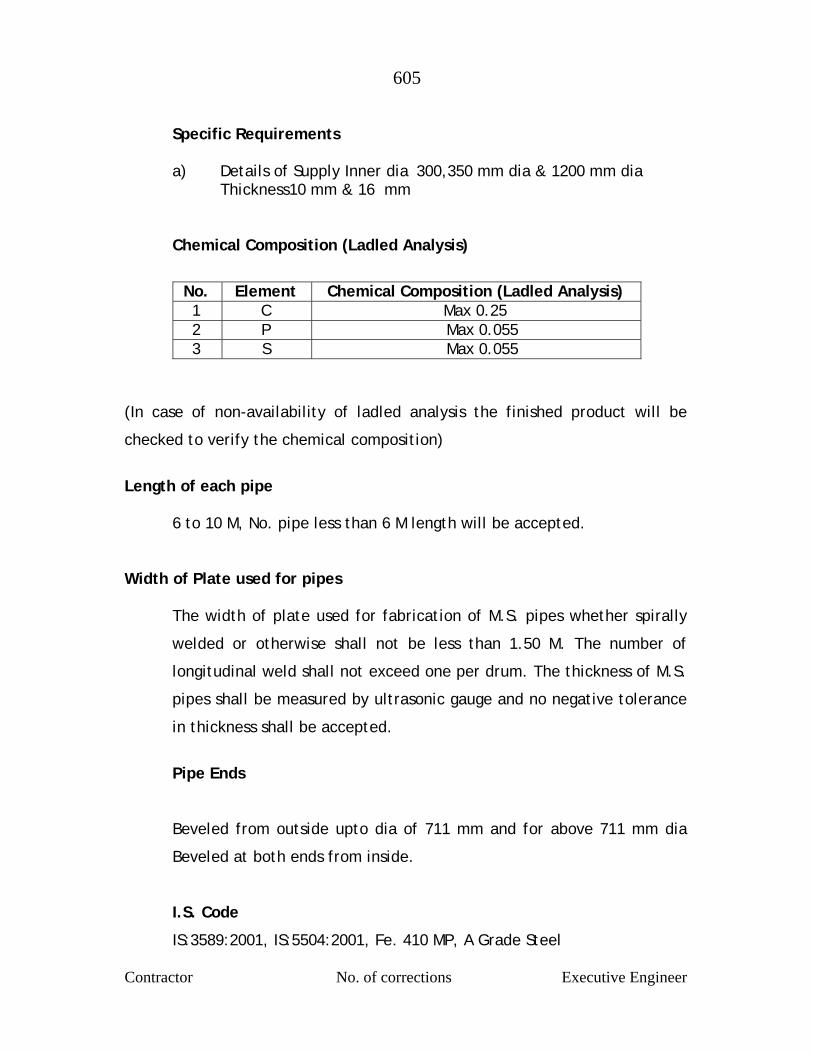
605
Contractor No. of corrections Executive Engineer
Specific Requirements
a) Details of Supply Inner dia 300,350 mm dia & 1200 mm dia Thickness10 mm & 16 mm
Chemical Composition (Ladled Analysis)
(In case of non-availability of ladled analysis the finished product will be
checked to verify the chemical composition)
Length of each pipe
6 to 10 M, No. pipe less than 6 M length will be accepted. Width of Plate used for pipes
The width of plate used for fabrication of M.S. pipes whether spirally
welded or otherwise shall not be less than 1.50 M. The number of
longitudinal weld shall not exceed one per drum. The thickness of M.S.
pipes shall be measured by ultrasonic gauge and no negative tolerance
in thickness shall be accepted.
Pipe Ends
Beveled from outside upto dia of 711 mm and for above 711 mm dia
Beveled at both ends from inside.
I.S. Code
IS:3589:2001, IS:5504:2001, Fe. 410 MP, A Grade Steel
No. Element Chemical Composition (Ladled Analysis) 1 C Max 0.25 2 P Max 0.055 3 S Max 0.055
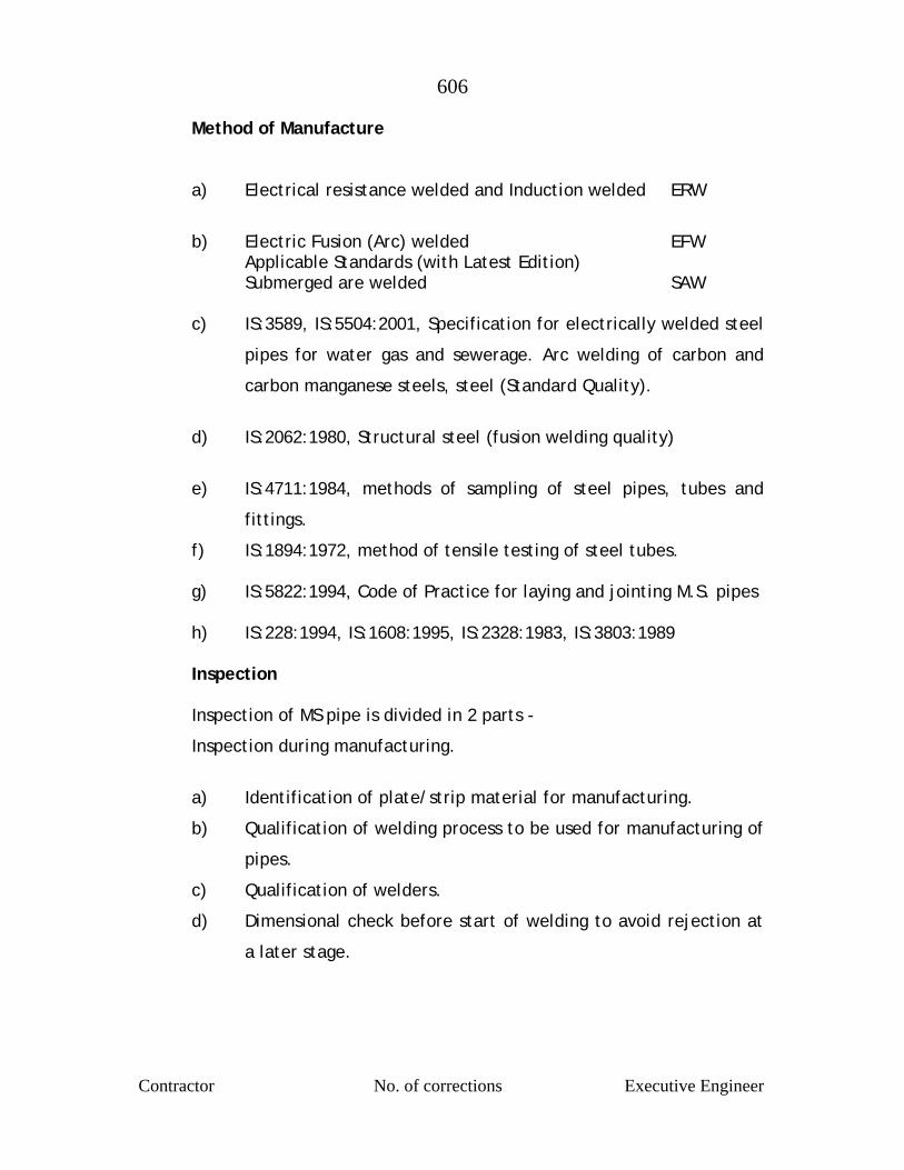
606
Contractor No. of corrections Executive Engineer
Method of Manufacture
a) Electrical resistance welded and Induction welded ERW
b) Electric Fusion (Arc) welded EFW
Applicable Standards (with Latest Edition) Submerged are welded SAW
c) IS:3589, IS:5504:2001, Specification for electrically welded steel
pipes for water gas and sewerage. Arc welding of carbon and
carbon manganese steels, steel (Standard Quality).
d) IS:2062:1980, Structural steel (fusion welding quality)
e) IS:4711:1984, methods of sampling of steel pipes, tubes and
fittings.
f) IS:1894:1972, method of tensile testing of steel tubes.
g) IS:5822:1994, Code of Practice for laying and jointing M.S. pipes
h) IS:228:1994, IS:1608:1995, IS:2328:1983, IS:3803:1989 Inspection
Inspection of MS pipe is divided in 2 parts -
Inspection during manufacturing.
a) Identification of plate/strip material for manufacturing.
b) Qualification of welding process to be used for manufacturing of
pipes.
c) Qualification of welders.
d) Dimensional check before start of welding to avoid rejection at
a later stage.
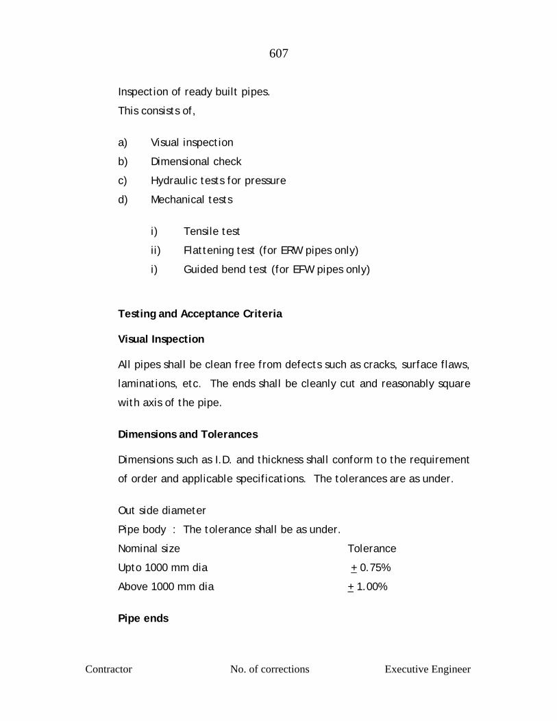
607
Contractor No. of corrections Executive Engineer
Inspection of ready built pipes.
This consists of,
a) Visual inspection
b) Dimensional check
c) Hydraulic tests for pressure
d) Mechanical tests
i) Tensile test
ii) Flattening test (for ERW pipes only)
i) Guided bend test (for EFW pipes only)
Testing and Acceptance Criteria
Visual Inspection
All pipes shall be clean free from defects such as cracks, surface flaws,
laminations, etc. The ends shall be cleanly cut and reasonably square
with axis of the pipe.
Dimensions and Tolerances Dimensions such as I.D. and thickness shall conform to the requirement
of order and applicable specifications. The tolerances are as under.
Out side diameter
Pipe body : The tolerance shall be as under.
Nominal size Tolerance
Upto 1000 mm dia + 0.75%
Above 1000 mm dia + 1.00%
Pipe ends
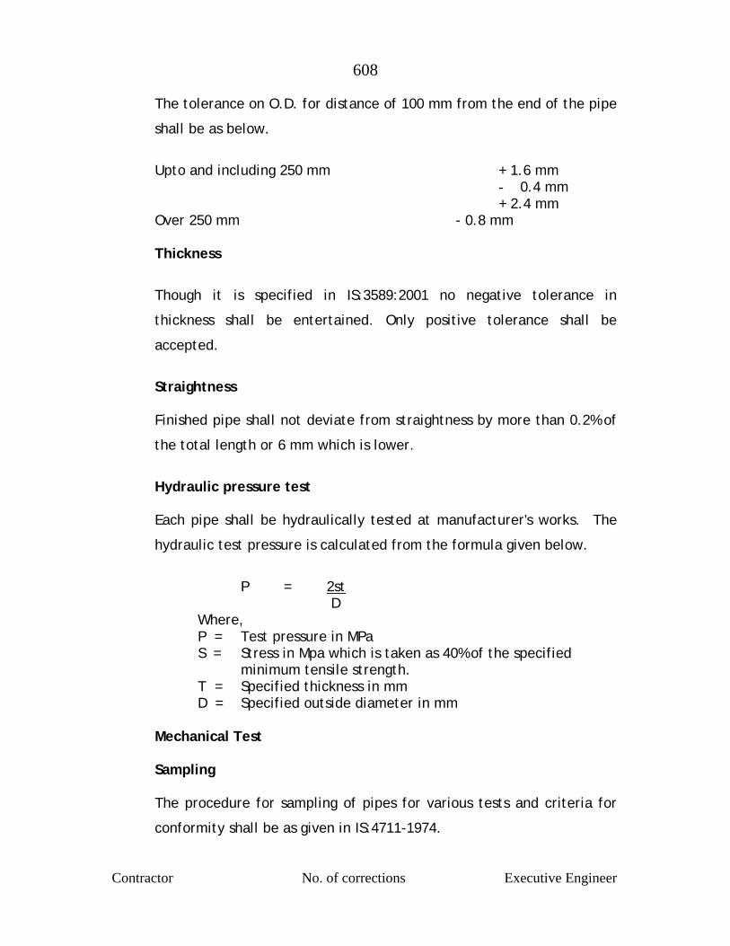
608
Contractor No. of corrections Executive Engineer
The tolerance on O.D. for distance of 100 mm from the end of the pipe
shall be as below.
Upto and including 250 mm + 1.6 mm
- 0.4 mm + 2.4 mm
Over 250 mm - 0.8 mm
Thickness
Though it is specified in IS:3589:2001 no negative tolerance in
thickness shall be entertained. Only positive tolerance shall be
accepted.
Straightness
Finished pipe shall not deviate from straightness by more than 0.2% of
the total length or 6 mm which is lower.
Hydraulic pressure test
Each pipe shall be hydraulically tested at manufacturer's works. The
hydraulic test pressure is calculated from the formula given below.
P = 2st D Where, P = Test pressure in MPa
S = Stress in Mpa which is taken as 40% of the specified minimum tensile strength.
T = Specified thickness in mm D = Specified outside diameter in mm
Mechanical Test
Sampling
The procedure for sampling of pipes for various tests and criteria for
conformity shall be as given in IS:4711-1974.

609
Contractor No. of corrections Executive Engineer
Tensile Test
Tensile test shall be carried out as per IS:1894-1972. The parent metal
of pipe is subjected for measurement of ultimate tensile and
elongation properties. Another sample is taken for testing of strength
of the weld. The ultimate tensile of which should normally be more
than or equal to ultimate tensile of parent metal. However, the
minimum mechanical properties for pipes as per IS:3589-2001 should
be as under.
Steel Grade
(Fe) Tensile Strength (Minimum Mpa)
Percentage
410 410 18
Flattening Test (for ERW/SAW pipes)
A ring not less than 40 mm length taken from one end of each selected
pipe shall be flattened between 2 parallel plates. The test shall be
taken by keeping the weld at 90o to the direction of the force. No
opening shall occur by fracture in the weld unit until the distance
between the plates is less than 66% of original O.D. of pipe and no
cracks or breaks on the metal elsewhere than in the weld shall occur
until the distance between the plate is less than 33% of original O.D.
The approved pipes are stamped on one end for identification by
inspecting authority.
Guided Bend Test (For EFW / SAW Pipes)
Strips 40 mm wide cut circumferentially from pipes or from coupons
plates attached to the welded with the pipes with weld in the middle
off the sample are taken for carrying out one face bend and one rood
bend. These are bent approx. 180o in a jig. The specimen shall not
fracture completely. Cracks 6.35 mm or less in length at the edge of
specimen of 3.18 mm or less in length in the center of the specimen
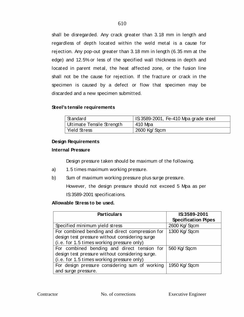
610
Contractor No. of corrections Executive Engineer
shall be disregarded. Any crack greater than 3.18 mm in length and
regardless of depth located within the weld metal is a cause for
rejection. Any pop-out greater than 3.18 mm in length (6.35 mm at the
edge) and 12.5% or less of the specified wall thickness in depth and
located in parent metal, the heat affected zone, or the fusion line
shall not be the cause for rejection. If the fracture or crack in the
specimen is caused by a defect or flow that specimen may be
discarded and a new specimen submitted.
Steel's tensile requirements
Standard IS:3589-2001, Fe-410 Mpa grade steel Ultimate Tensile Strength 410 Mpa Yield Stress 2600 Kg/Sqcm
Design Requirements
Internal Pressure
Design pressure taken should be maximum of the following.
a) 1.5 times maximum working pressure.
b) Sum of maximum working pressure plus surge pressure.
However, the design pressure should not exceed 5 Mpa as per
IS:3589-2001 specifications.
Allowable Stress to be used.
Particulars IS:3589-2001 Specification Pipes
Specified minimum yield stress 2600 Kg/Sqcm For combined bending and direct compression for design test pressure without considering surge (i.e. for 1.5 times working pressure only)
1300 Kg/Sqcm
For combined bending and direct tension for design test pressure without considering surge. (i.e. for 1.5 times working pressure only)
560 Kg/Sqcm
For design pressure considering sum of working and surge pressure.
1950 Kg/Sqcm
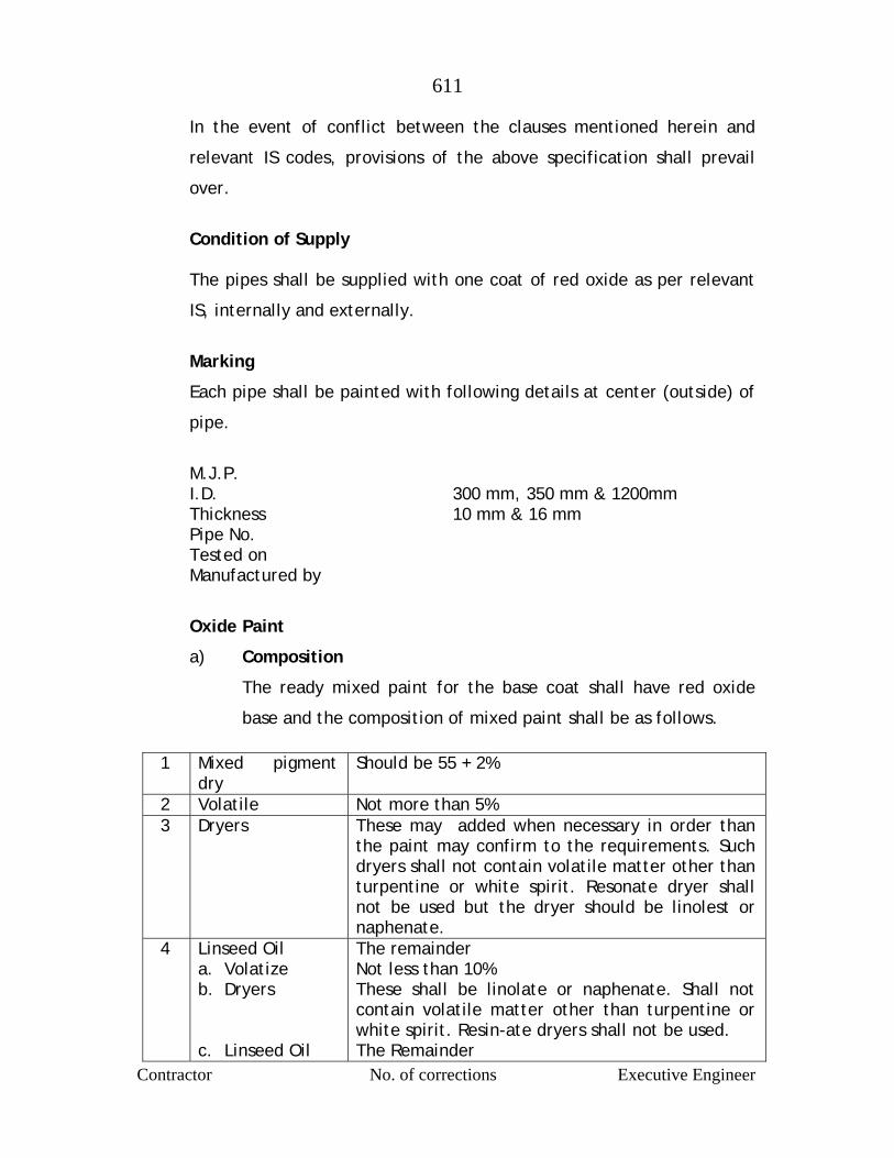
611
Contractor No. of corrections Executive Engineer
In the event of conflict between the clauses mentioned herein and
relevant IS codes, provisions of the above specification shall prevail
over.
Condition of Supply
The pipes shall be supplied with one coat of red oxide as per relevant
IS, internally and externally.
Marking
Each pipe shall be painted with following details at center (outside) of
pipe.
M.J.P. I.D. 300 mm, 350 mm & 1200mm Thickness 10 mm & 16 mm Pipe No. Tested on Manufactured by
Oxide Paint
a) Composition
The ready mixed paint for the base coat shall have red oxide
base and the composition of mixed paint shall be as follows.
1 Mixed pigment dry
Should be 55 + 2%
2 Volatile Not more than 5% 3 Dryers These may added when necessary in order than
the paint may confirm to the requirements. Such dryers shall not contain volatile matter other than turpentine or white spirit. Resonate dryer shall not be used but the dryer should be linolest or naphenate.
4 Linseed Oil a. Volatize b. Dryers c. Linseed Oil
The remainder Not less than 10% These shall be linolate or naphenate. Shall not contain volatile matter other than turpentine or white spirit. Resin-ate dryers shall not be used. The Remainder
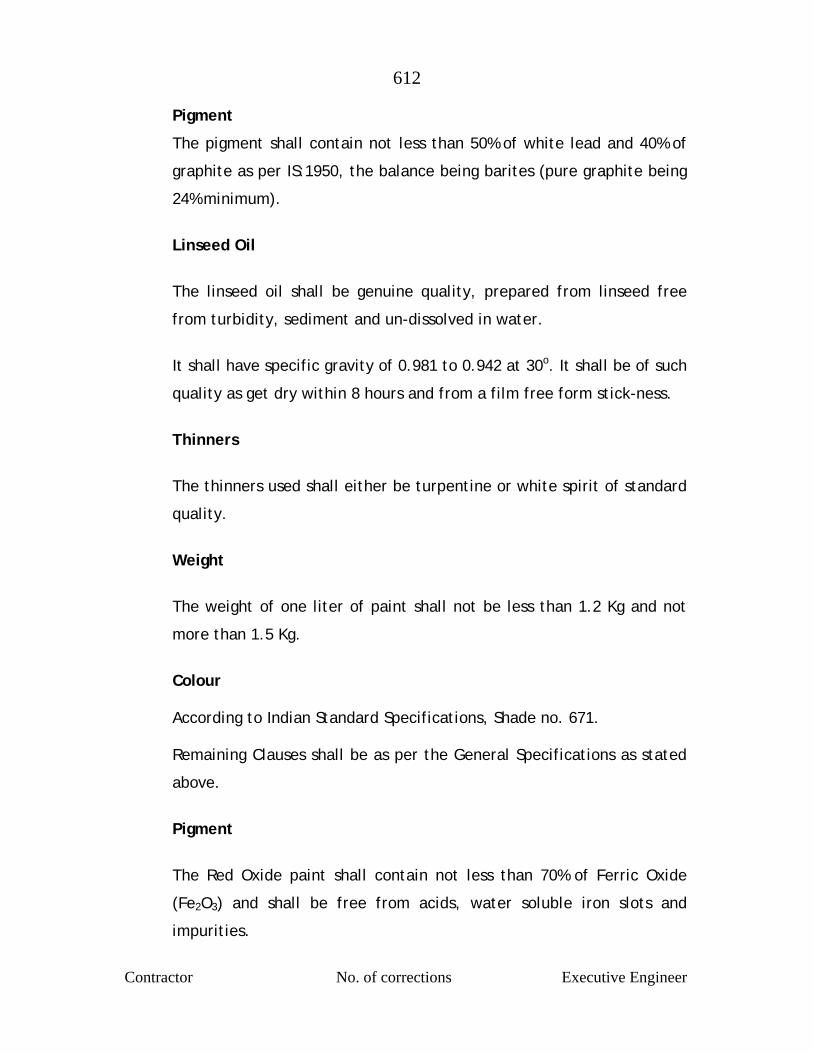
612
Contractor No. of corrections Executive Engineer
Pigment
The pigment shall contain not less than 50% of white lead and 40% of
graphite as per IS:1950, the balance being barites (pure graphite being
24% minimum).
Linseed Oil
The linseed oil shall be genuine quality, prepared from linseed free
from turbidity, sediment and un-dissolved in water.
It shall have specific gravity of 0.981 to 0.942 at 30o. It shall be of such
quality as get dry within 8 hours and from a film free form stick-ness.
Thinners
The thinners used shall either be turpentine or white spirit of standard
quality.
Weight
The weight of one liter of paint shall not be less than 1.2 Kg and not
more than 1.5 Kg.
Colour
According to Indian Standard Specifications, Shade no. 671. Remaining Clauses shall be as per the General Specifications as stated
above.
Pigment
The Red Oxide paint shall contain not less than 70% of Ferric Oxide
(Fe2O3) and shall be free from acids, water soluble iron slots and
impurities.
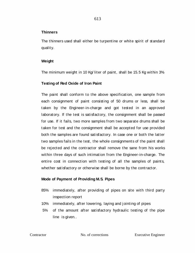
613
Contractor No. of corrections Executive Engineer
Thinners
The thinners used shall either be turpentine or white spirit of standard
quality.
Weight
The minimum weight in 10 Kg/liter of paint, shall be 15.5 Kg within 3%.
Testing of Red Oxide of Iron Paint
The paint shall conform to the above specification, one sample from
each consignment of paint consisting of 50 drums or less, shall be
taken by the Engineer-in-charge and got tested in an approved
laboratory. If the test is satisfactory, the consignment shall be passed
for use. If it fails, two more samples from two separate drums shall be
taken for test and the consignment shall be accepted for use provided
both the samples are found satisfactory. In case one or both the latter
two samples fails in the test, the whole consignments of the paint shall
be rejected and the contractor shall remove the sane from his works
within three days of such intimation from the Engineer-in-charge. The
entire cost in connection with testing of all the samples of paints,
whether satisfactory or otherwise shall be borne by the contractor.
Mode of Payment of Providing M.S. Pipes
85% immediately, after providing of pipes on site with third party
inspection report
10% immediately, after lowering, laying and jointing of pipes
5% of the amount after satisfactory hydraulic testing of the pipe
line is given..

614
Contractor No. of corrections Executive Engineer
After laying the entire pipeline, if there is any surplus pipes
which are decided to be retained by the M.J.P., the 100% of the
rate of supply shall be payable after stacking properly in the
M.J.P’s store within the project area.
Item No.3 – Providing & supplying ISI mark D.I. flanged, S & S specials etc.
complete
Item shall be carried out as per Detailed Specification of Item No.1 of Sub Work No.7
Item No.4 – Supplying of C.I. mechanical Collar Coupling (Jiffy Joint) etc.
complete
Item shall be carried out as per Detailed Specification of Item No.4 of Sub Work No.7
Item No.5 – Excavation for foundation / pipe trenches in average all types
of strata of earth, soils etc. complete.
Item shall be carried out as per Detailed Specification of Item No.6 of Sub Work No.7
Item No.6 – Filling in plinth and floors murum bedding in trenches etc.
complete.
Item shall be carried out as per Detailed Specification of Item No.7 of Sub Work No.7
Item No.7 – Refilling the trenches etc. complete.
Item shall be carried out as per Detailed Specification of Item No.8 of Sub Work No.7
Item No.8 Providing & laying in situ cement concrete M-150 etc. complete.
Item shall be carried out as per Detailed Specification of Item No.9 of Sub Work No.7
Item No.9 – Providing and casting in situ cement concrete of RCC work in
M-200 etc. complete.

615
Contractor No. of corrections Executive Engineer
Item shall be carried out as per Detailed Specification of Item No.20 of Sub Work No.13
Item No.10 – Providing & fixing in position steel bar reinforcement etc.
complete.
Item shall be carried out as per Detailed Specification of Item No.5 of Sub Work No.1
Item No.11 – Lowering, laying and jointing D.I. Pipes etc. complete
Item shall be carried out as per Detailed Specification of Item No.10 of Sub Work No.7
Item No.12 – Lowering, laying in position to correct line UNDER GROUND PIPE LAYING
(Bare M.S. Pipeline and Gunitted Pipes/outside coated pipes). GENERAL :
Underground pipe laying under this contract shall be done for
pipeline to be laid along State Highway and major District road
residential zone through village, town or crossing of the roads or cart
track for portion along nalla bank and also below the road portion.
Pipe laying shall be done as shown on the drawings or as directed
by Engineer, to the correct line and level. The Engineer, at his
discretion, may change the alignment and/or levels depending on
the site conditions. The minimum cover under roadway etc. where
traffic is expected over the pipeline shall be 120 cm as specified in
IS:5822. The minimum cover for pipeline along the major district
road and State Highway shall generally be 1.0 m, where traffic is not
expected over the pipeline.
Pipes and specials to be laid underground shall be provided either
with C.M. gunitting Coaltar wrapping or cement concrete encasing as
616
Contractor No. of corrections Executive Engineer
specified separately as per requirement. Care shall be taken to see
that while handling these pipes, the pipe and gunitted portion is not
damaged. The rate for lowering and laying gunitted pipes/bare pipes
as specified in the relevant item of Schedule 'B' of respective Sub-
Works, includes all expenses on account of labour, machinery,
material etc. required for complete process of laying. No extra rate
for any reason for this job will be admissible even if the process of
lowering and laying of these pipes requires additional labour,
machinery, materials etc. from safety point of view.
LAYING PROCEDURE :
The contractor shall lower the pipes of standard lengths. Short
length pipes shall be lowered only if found necessary and only after
obtaining the permission of Engineer-in-Charge. The pipes shall be
lowered in the trench on prepared bedding or concrete bedding as
per the decision of Engineer-in-Charge. Pipes shall not be laid on the
open rock bottom as it may damage the pipe shell on account of point
loads.
The alignment and levels shall be checked by the theodolite.
Cutting of pipes shall not be allowed for matching the sides of
trenches excavated. While assembling the pipes the ends shall be
brought close enough to leave a uniform gap not exceeding 3 mm.
Marginal cutting and grinding shall be done if found necessary, for
which no extra payment shall be made. There shall be no lateral
displacement between pipe faces to be jointed.
When the pipe is properly assembled and checked by Engineer-in-
Charge for correct line and level, it shall be firmly supported on
wooden beams and wedges and then tack welded.
617
Contractor No. of corrections Executive Engineer
In the trenches where shoring is provided, care shall be taken to see
that during lowering of pipes, only required struts are removed at a
time with additional precautions to keep the shoring in position
if necessary.
MEASUREMENT AND PAYMENT :
The laying shall be measured as per linear meter of pipeline/specials,
like bends, tapers, distance pieces etc. laid measured along the center
line on top of the pipe, and paid for under measurement. The rate
shall include supply of all labour, materials, machinery for laying the
pipes below ground including local handling with all lead inclusive of
hoisting and lowering in position, tack welding including marginal
cutting wherever necessary. Laying of specials and full field welding
of joints shall be paid for separately under the relevant items in the
Bill of Quantities and Rates.
NOTE : No extra payment for transportation of bare or gunited
M.S. pipes including loading, unloading and carting is admissible if the pipes are required to be stacked at more than 500 M from the pipeline alignment, due to site condition. Before quoting offer, contractor shall verify the site condition. However, 10% amount will be withheld till satisfactory hydraulic testing is given.
SPECIAL PRECAUTIONS FOR MAINTAINING CIRCULAR SHAPE OF PIPE
Special attention of the tenderer is drawn to the fact that the
proposed pipeline may be provided with cement mortar lining. It is
therefore very necessary that the circular shape of the pipes is
maintained till these pipes are mortar lined. The contractor shall
provide adjustable steel struts of the approved design for this
purpose. Minimum three sets of struts shall be provided per pipe
length of 6 meter. They shall be retained till complete refilling is
done and properly consolidated or till concrete encasing is set. Any
618
Contractor No. of corrections Executive Engineer
diametric variation beyond + 2% shall have to be rectified by
the contractor at his cost, which may include, removing the section of
the pipeline and relaying it along with all other ancillary operations.
Providing required number of adjustable struts and all other operations
involved as above shall be deemed to have been included in the item
of gunitting and laying and no separate payment on this account will
be admissible.
Item No.13 –Providing and supplying ISI standard M.S. specials….etc
complete Item shall be carried out as per Detailed Specification of Item No.11 of
Sub Work No.1 Item No.14 –Gas cutting either square cut or V cut pipes etc. complete.
GENERAL
Gas cutting of M.S. Pipes may require to be adopted on site for
fabrication of bends on site or for preparing distance pieces, straps
etc. and for cutting holes in pieces for manholes, branches scour
valves, Air Valves and other appurtenances and temporary manholes
for cleaning welding etc..
After gas cutting the edges shall be made smooth and even so as to
remove all the equalities ends of the pipe shall have ‘V’ edge from in
side.
MEASUREMENT AND PAYMENT
Gas cutting shall be measure in linear meters of gas cutting done and
shall be paid for in this item and rates shall include all labour materials
and machinery for gas cutting irrespective of any circumstances, shall
619
Contractor No. of corrections Executive Engineer
ancillary preparation and including chamfering the ends to form ‘V’
edges.
NOTE : For preparing M.S. specials from bare pipes supplied by agency, payment for gas cutting will not be made under this item. 10% amount will be withheld till satisfactory testing is given.
Item No.15 – Welding in all position with required Nos. of runs for M.S.
Pipes etc.
GENERAL
Before aligning, assembling and welding the pipe faces shall be
cleared by scraping with wire brushes or by any other method
approved by the Engineer.
Welding of pipes in field shall conform to ISS:816-1969 (code of
practice for use of metal are welding for general construction in
Mild Steel). In case of variance, specifications hereunder shall
have precedence.
Welders shall be experienced and approved by the Engineer-in -
Charge to do the welding at the locations welding shall not be
allowed to be done by helpers. Contractor shall remove such of the
welders from the job, whose work is not found to be satisfactory.
The Engineer may ask them to do test welding before approving
their employment on the job.
The contractor shall keep record of the welding for each
circumferential joint. It shall contain the name of the Welder,
Operator and Date of Completion of such run of internal and external
welding.
GAUSING AND CHIPPING
M.S. Pipes of diameter larger than 1016 mm shall be welded with
two number of runs from inside and a sealing run from outside.
620
Contractor No. of corrections Executive Engineer
External sealing run shall be done only after internal welding is
completed. Before starting the external welding the weld material in
the joint shall be cleaned by clipping out loose scales. Gausing shall
be done before rectification of any defective welding wherever
necessary and as directed by the Engineer.
Gausing or chipping shall not be paid for separately and the rate for
welding shall be deemed to include the cost of gausing.
ELECTRODES
Welding electrodes to be used for welding in this contract shall
conform the Indian Standard Specifications ISS:814- 1971
(Specifications for covered electrodes for metal are welding of
Mild Steel).
The contractor shall use of Advani and Premium Co. electrodes
depending on the thickness of the plates to be welded and the type
of joint. The contractor shall also use standard current and A.C.
voltage required for the machine as per manufacturer's directions.
TYPES OF WELDED JOINTS
The circumferential joints of the pipes shall be butt welded with
required number of runs externally and internally.
All fillet welds shall have a throat thickness not less than 0.7.times the
thickness of the pipe to be welded.
WELDING PROCEDURE
All parts of pipes, specials, etc. shall have all loose scale, slag, rust,
paint and any other foreign material shall be removed with wire brush
621
Contractor No. of corrections Executive Engineer
and left clean and dry. All scale and slag shall be removed from each
run of weld when that run is completed.
Openings in the form of manholes in the laid pipeline at suitable
distance of access for the work of cleaning, repairs etc. Such
manholes, as far as possible, shall be provided on sides of the pipe
line and cutting manholes at the crown shall be strictly avoided.
Patch Plates for plugging the above manholes shall be cut from a
separate pipe of the same diameter. Edges of the patch plate shall be
properly shaped and shall be inserted in the opening leaving a gap of 3
to 4 mm and tacked. Welding of patch plate shall be done in
segments in a proper sequence conforming to Indian Standard
Specifications IS:623
TESTING OF WELDED JOINTS
Welded joints shall be tested in accordance with procedure laid
down in Indian Standard Specifications (IS:3600, Part I-1985 of
procedure for Testing Fusion welded joints and weld metals in steel).
At least one test specimen shall be taken out for testing for every
fifty field joints done. Test pieces shall be taken out from the places
pointed out by the Engineer. These shall be machined and tested as
early as possible.
The shape of the test pieces removed for testing shall be such that it
shall give the specimen of the required dimensions with the weld in
the middle of the specimen and at the same time leave the holes in
the pipe with rounded corner. This hole shall be patched with a plate
of suitable size cut from a separate pipe of same diameter. It must
ensure good butt weld.
622
Contractor No. of corrections Executive Engineer
Welded joints shall be checked by Radiography test for each and every
pipe. The expenses for this shall bear by the contractor.
TENSILE TEST
The test specimen taken perpendicularly across the weld shall be
shaped in accordance with Indian Standard Specification IS:223. The
tension test specimen shall be machined. The protruding welded
portion from inside as well as outside shall be removed by machining
before the specimen is tested.
If the specimen shows defective machining or develops flaws not
associated with welding. It shall be discarded and another specimen
substituted. The welded joint shall show a strength not less than the
minimum tensile strength for the plate in accordance with IS:2026.
BEND TEST
Bend Test specimen shall also be prepared in the same fashion as
the tensile test specimen. The specimen shall stand being bent cold
180o around a pin that has a diameter equal to 4.5 times the plate
thickness. Without developing cracks. For this test face
representing inside of the pipe shall be placed next to the pin.
TRE-PANNED PLUGS
Tre-panned plugs shall be taken out from any welded portion out by
the Engineer. These plugs shall not show any defect in welding such as
inclusion of slag, blow slowly filled with clean water by opening cross
connection with the existing mains or otherwise by pumping water into
the line (Water and pumping arrangement is to be arranged by the
contractor) AS DIRECTED and all air shall be expelled from the pipeline
through hydrants, air valves and blow offs fixed on the pipeline. Once
the pipeline is full the cross section or pumping shall be closed. The
623
Contractor No. of corrections Executive Engineer
pressure in the pipe line should then be raised in stages and built up
and maintained by means of suitable approved pumps to the specified
test pressure based on the elevation of the lowest point on the line or
section under test.
The test pressure shall be as the specified in IS:5822:1994. Before
starting the pressure test, the expansion joints shall be tightened, the
pressure shall be maintained for a least 24 hours. The drop in pressure
shall not exceed 0.7 Kg/Sqcm within a period of 2 hours, after the full
test pressure is built-up. Under this pressure no lead or sweating shall
be visible at the welded joints. During the test, the pipe line shall be
struck sharp blow with 1.5 Kg hammer. Water shall not spot, ooze or
sweat through any part. In case of any leak observed anywhere in the
field joints, whether welded or bolted, the same shall be repaired,
welded entirely at the contractor’s cost with re-gunitting etc. The
repaired joints shall be subjected to retest. No section shall be
accepted unless it is perfectly water tight.
The entire cost of testing, retesting, including cost of water shall be
paid under relevant item of Bill of Quantities. The contractor shall
make all the arrangements for all labour, pumps, pressure gauge,
equipments, etc. The gauges should be got tested if insisted by the
Engineer-in-charge. The contractor shall arrange for labour required
for operating air valves, scour valves, etc. complete.
The hydraulic testing of the water main will be carried out for entire
length as directed by Engineer-in-Charge. If any leakages are
observed even during defects liability period due to defective
workmanship, the same shall be rectified immediately. The charges of
repairs if done departmentally will be recovered from the amount of
retention money. Repairs on live water mains are to be carried out
immediately to avoid wastage of water and other problems such as

624
Contractor No. of corrections Executive Engineer
disruption of water supply and traffic etc. In view of this, it will be
very difficult to give prior intimation to concerned contractor. As
such the cost of repairs, being the expenditure will be recovered
from the contractor's retention money withheld in deposit without
giving any prior intimation. The contractor will not challenge or claim
any extra for such action on the part of the Department. The plug
shall be 12 mm in diameter in the pipe shall either be filled back by
inserting 1 steel stud and welding around or threading the hole and
providing suitable G.I. plug. This test shall be done only if considered
necessary by the Engineer-in-Charge.
PROCEDURE OF FAILURE OF TEST SPECIMEN
If the test fails in either tensile or bend test or in both, two
additional test specimen shall be taken out from the section and shall
be tested for tensile and bend tests. If any one of them fails,
extensive Gausing and rewelding shall be done for the welded joints
in that section to the full satisfaction of the Engineer. However, if
both the samples give satisfactory results, the joint from which the
original sample was taken and had failed shall be repaired to the
satisfaction of the Engineer by Gausing and welding etc. at
contractor's cost.
Welder who has done the welding of the joint that has failed shall
be solely held responsible for bad workmanship and failure. Since
all other factors like electrodes, current, arc voltage etc. are
already controlled, on negligence on the part of the welder only is
responsible for such failure. For first such failure the welder shall be
warned and if the welded joint done by him fails for the second
time, he shall be removed from the job.
625
Contractor No. of corrections Executive Engineer
MEASUREMENT AND PAYMENT
Welding shall be paid in linear meter of welding done including the
required number of runs. The welding shall be paid for in the relevant
item of welding butt joint or lap joint in respective items in the Bill of
Quantities and Rates. The rate shall include providing all labour,
material and welding machinery including all ancillary preparations
and testing, repairing, retesting, Gausing etc. complete in all
positions and circumstances prevailing on site. No extra payment on
any account whatsoever may be admissible to contractor. 10% of the
amount under this item will be withheld till the satisfactory hydraulic
testing is given.
NOTE : For preparing specials from pipe, welding payment under this item will not be made.
Item No.17 – Providing & applying HDPE coating for M.S. pipe internally as
well as externally etc. complete.
The item includes providing & applying externally and internally HDPE
coating to the M.S. pipes as per CSA Z245.21 system B2. The M.S. pipes
prior to coating shall be cleaned by compressed air. The pipes shall be
free from dust, oil grease & moisture prior to application of coating.
The three layer HDPE coating system shall comprise of a powder epoxy
primer, a powdered grafted polymeric adhesive and a powdered
polyethylene top coat. Coating materials shall be suitable for the
service conditions and the pipe size involved. The coating martial i.e.
epoxy powder, adhesive and polyethylene compound shall have proven
compatibility. The top coat of polyethylene used shall be a black
readymade compound, fully stabilized against influence of ultraviolet
reaction (i.e. sunlight), oxygen in air and heat (due to environmental
temperature). No appreciable changes shall occur during exposure to
such environments upto at least a period of 6 months. The item
626
Contractor No. of corrections Executive Engineer
includes cost of loading, unloading & handling of pipes at factory etc.
completed as directed by Engineer-in-Charge.
All coated pipes shall be 100% electrically inspected by high voltage.
The test for the bonding of 3 LPE coating to steel pipe should be bond
test as per ASTMD 4541. Reasonable care shall be exercised with
coated pipe to ensure the integrity of the coating prior to installation.
End hooks (aluminum), brass / padded with non-metallic slings or
padded clips shall be used while loading, unloading & handling the
pipes. The storage area shall be free from rocks, stones, sticks & other
protrusion & shall be well drained 3 layer polyethylene coated pipes
may be stored outside for a period of maximum six months only. The 3
LPE coated steel pipes are intended to be laid underground only.
Mode of payment
The item shall be measured and paid on Sqmt. basis.
Item No.18 – Providing & fixing in position C.I. Air Valves etc. complete.
Item shall be carried out as per Detailed Specification of Item No.5 of Sub Work No.4
Item No.19 Providing & supplying double flanges sluice valve etc. complete
Item shall be carried out as per Detailed Specification of Item No.3 of Sub Work No.7
Item No.20 – Lowering, laying and jointing in position CI double flanged
sluice valve etc. complete.
Item shall be carried out as per Detailed Specification of Item No.11 of Sub Work No.7
Item No.21 – Providing & constructing BB masonary valve chamber etc.
complete.
627
Contractor No. of corrections Executive Engineer
Item shall be carried out as per Detailed Specification of Item No.12 of Sub Work No.7
Item No.22 – Lowering, laying in position M.S. specials etc. complete
The tender item covers lowering, laying & jointing M.S. Specials as per requirement and as directed by the Engineer-in-Charge. The cost of conveyance of these materials from place of the site of work is also included in the tender item.
Mode of payment
The item shall be measured and paid on Rmt. basis. Dimension shall be
measured correct to two decimal meter. The 15% payment shall be
with held for till satisfactory hydraulic testing is given.
Item No.23 – Hydraulic testing of M.S. pipe line etc. complete.
After the work of laying pipeline is completed and before it is
commissioned, the pipeline shall be tested prior to painting in the
field both for its strength and leakage in the following manner.
NOTE
Whether stated specifically elsewhere or not, the testing in section of 0.5 to 1 km shall have to be completed within 3 months of laying and jointing. Delay in testing will be subject to a fine at 5% of the cost of the testing item for delay of every month or part thereof.
The pipeline laid length will be divided into sections specified by
Engineer-in-Charge. The contractor shall recheck pipe and valves for
cleanliness and shall recheck operations of the valves. The open ends
of the pipeline or sections thereof shall normally be stopped off
by blank flanges or cap ends additionally secured where necessary by
temporary struts and wedges. All anchor and thrust blocks must have
been completed and all pipe straps and other devices intended to
prevent movement of pipe must have been securely fastened.
628
Contractor No. of corrections Executive Engineer
The contractor shall clean out the whole pipeline and flush it with
water, so as to remove dust, dirt and any foreign matter laying in the
pipeline. No separate payment for the work of cleaning will be made
and the rates under various items of work include thereof.
Each valve section of the pipeline shall be subjected to hydraulic test
in section. For this test, the pipe shall be slowly filled with clean
water by pumping water into the line (water and pumping
arrangement is to be arranged by contractor) as directed and all
air shall be expelled from the pipeline through hydrants, air valves
and blow off fixed on the pipeline. Once the pipe is full, the cross
connection or pumping shall be closed. The pressure in the pipeline
should then be raised in stages and built up and maintained by means
of suitable approved pumps, to the specified test pressure based on
the elevation of the lowest point on the line or section under test.
The test pressure shall be not less than 15.00 kg/cm2 test pressure,
or 1.5 times the working pressure, whichever is higher. Before
starting the pressure test, the expansion joint shall be tightened, the
test pressure shall be maintained for at least 24 hours. The drop in
pressure shall not exceed 0.7 kg/cm2 within a period of 2 hours
after the full test pressure is built-up. Under this pressure no leak or
sweating shall be visible at the welded joints. During the test, the
pipe shall be struck sharp blows with 1.5 kg hammer. Water shall
not spout, ooze or sweat through any part. In case of any leak
observed anywhere in the field joints whether welded or bolted, the
same shall be repaired entirely at the contractor's cost which shall
include repairs to welding and regunitting etc. The repaired joint shall
be subjected to retest. No section shall be accepted unless it is
perfectly watertight.
629
Contractor No. of corrections Executive Engineer
The entire cost of testing, retesting including cost of water taken
together shall be paid under relevant item of Bill of Quantities. The
contractor shall make all the arrangements for all labour, pumps,
pressure gauge equipment etc. The gauges should be got tested if
insisted by the Engineer-in-Charge. The contractor shall arrange for
labour required for operating air valves, scour valves etc. Any labour of
Corporation employed for the above activities of the test other
than supervision shall be charged to the contractor as per rules.
The hydraulic testing of the water main will be carried out for entire
length as directed by Engineer-in-Charge. If any leakages are
observed even during defects liability period due to defective
workmanship, the same shall be rectified immediately. The charges of
repairs if done departmentally will be recovered from the amount of
retention money. Repairs on live water mains are to be carried out
immediately to avoid wastage of water and other problems such as
disruption of water supply and traffic etc. In view of this, it will be
very difficult to give prior intimation to concerned contractor. As
such the cost of repairs, being the expenditure will be recovered
from the contractor's retention money withheld in deposit without
giving any prior intimation. The contractor will not challenge or claim
any extra for such action on the part of the Department.
Mode of payment
The item shall be measured and paid on Km. basis. Item No.24 Providing and fixing in position spacers at 3 M c/c etc.
complete.
The item includes of providing and fixing HDPE Spacers between
casing pipe and carrier pipes at 3 mtrs. c/c as per approved drawing
and as directed by Engineer in charge.
630
Contractor No. of corrections Executive Engineer
Mode of payment The item shall be measured and paid on Per Number basis. Item No.25 – Providing second class burnt brick masonary in c.m. 1:6 in
superstructure etc.complete.
The B.B. masonary wall of minimum thickness 23 cm in CM 1:6 with the
specification lays down the requirements for B.B. Masonary 1st class in
cement mortar 1:6 required for various structures, including necessary
scaffolding, watering etc. The specification shall conform to IS: 2212-
1991 its latest revision.
Mode of payment
The item shall be measured and paid on Cum. basis.
Item No.26 – Supplying labour (light) for fixing brick and other allied work for railway crossing etc. complete
Mode of payment
The item shall be measured and paid on Per Number basis. Item No.27 – Providing 50mm (about 2”) thick full grout bituminous road
surface etc. complete.
Item shall be carried out as per Detailed Specification of Item No.13 of
Sub Work No.7
Item No.28: Making cross connection to existing distribution main etc.
complete.
Item shall be carried out as per Detailed Specification of Item No.19 of
Sub Work No.7
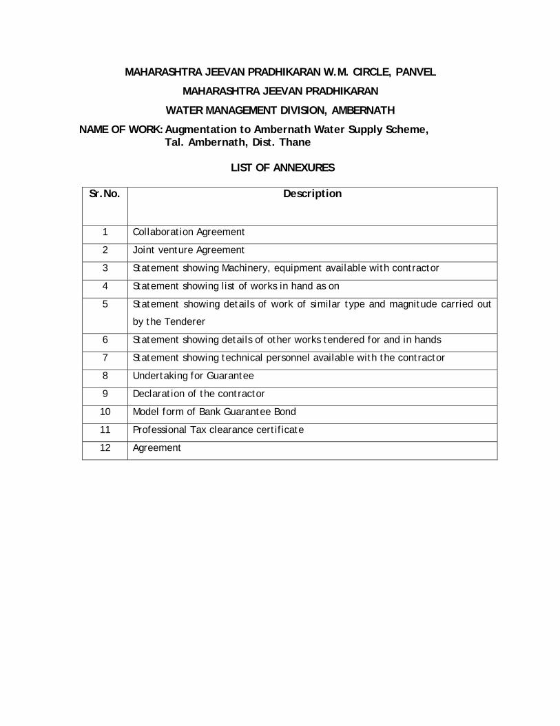
MAHARASHTRA JEEVAN PRADHIKARAN W.M. CIRCLE, PANVEL
MAHARASHTRA JEEVAN PRADHIKARAN
WATER MANAGEMENT DIVISION, AMBERNATH
NAME OF WORK: Augmentation to Ambernath Water Supply Scheme, Tal. Ambernath, Dist. Thane
LIST OF ANNEXURES
Sr.No. Description
1 Collaboration Agreement
2 Joint venture Agreement
3 Statement showing Machinery, equipment available with contractor
4 Statement showing list of works in hand as on
5 Statement showing details of work of similar type and magnitude carried out
by the Tenderer
6 Statement showing details of other works tendered for and in hands
7 Statement showing technical personnel available with the contractor
8 Undertaking for Guarantee
9 Declaration of the contractor
10 Model form of Bank Guarantee Bond
11 Professional Tax clearance certificate
12 Agreement

631
Contractor No. of corrections Executive Engineer
ANNEXURE-I
COLLABORATION AGREEMENT
This agreement made at (Place) this day
(date, month and year) between M/s.
(Name of the bidder, who intends to collaborate and its registered office address)
here-in-after referred as (Principal contractor) which expression shall unless it be
repugnant to the context or contrary to the meaning there of be deemed to mean and
includes its successors in business and permitted assigns of the ONE PART and (name of
the collaborator and its registered address) here-in-after referred as (Collaborator)
which expression shall unless it be repugnant to the context or contrary to the
meaning there of be deemed to mean and includes its successors in business and
permitted assigns of the OTHER PART.
WHERE AS
(1) Maharashtra Jeevan Pradhikaran has floated a tender for the work related to
Augmentation to Ambernath Water Supply Scheme Taluka Ambernath, District
Thane.
(2) (Principal contractor) registered with Maharashtra Jeevan Pradhikaran in Class-I
is a well established company engaged in the activities inter-aliea (Details of
the work, in which the company engaged and various other applications).
(3) (Collaborator) registered with in Class-I is well
established company engaged in the activities inter-aliea (Details of activities).
(4) The Parties hereto have come together to set up a collaboration in order to
quote for the above tenders and on award of the works to jointly execute the
above work as well as to guarantee there perfect execution utilizing the
technical experience. The principal contractor involved in this collaboration,
directly or indirectly will hold full responsibility towards Maharashtra Jeevan
Pradhikaran to look after the execution of the said work accordingly to the
terms and conditions here-in-after.

632
Contractor No. of corrections Executive Engineer
NOW IT IS HEREBY AGREED BY AND BETWEEN THE PARTIES HERETO AS UNDER :-
1) In consideration of the mutual understanding, trust and confidence each of the
parties in other, they have mutually agreed to form a collaboration to submit
the tender and if the tender is accepted by the Maharashtra Jeevan
Pradhikaran then carry on the business as a collaboration in respect of
development and execution of the said work in accordance with the terms and
conditions that may be imposed or agreed by and between the Maharashtra
Jeevan Pradhikaran and the Principal contractor hereto.
2) The collaborator shall be responsible for completion of works for which the
collaboration is made, however the principal contractor shall be ultimately
responsible and liable for completion of entire works in accordance with the
terms and conditions on which the award to execute the work is made by
Maharashtra Jeevan Pradhikaran under the said tender.
3) In the event of any dispute or difference or misunderstanding arises between
both of them in course of execution of the work after the award of the work to
the Principal contractor by Maharashtra Jeevan Pradhikaran, the same shall be
referred to Member Secretary, Maharashtra Jeevan Pradhikaran and his
decision in this respect shall be final and binding on both the parties.
IN WITNESS WHERE OF the parties hereunto have set and subscribed there
respective hands and seals the day, month and year first above written.
SIGNED, SEALED AND DELIVERED BY THE WITH NAME (Name of First Party) (Name of Second Party) WITNESS :- 1. 2.
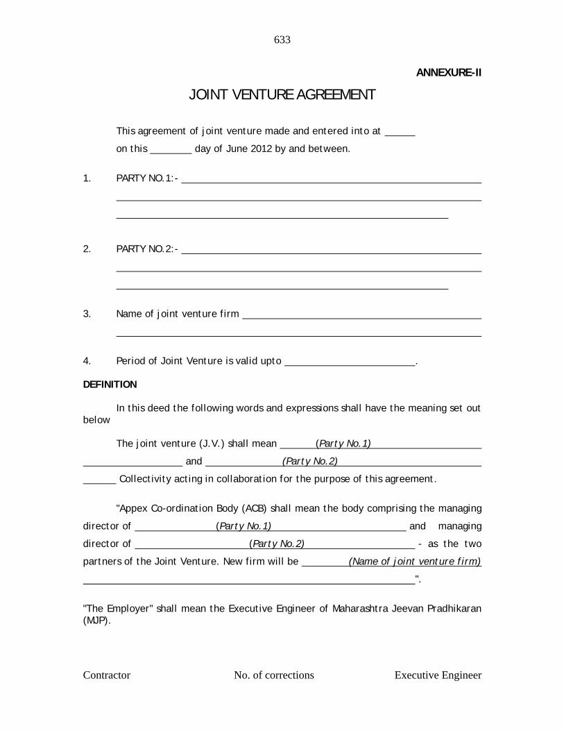
633
Contractor No. of corrections Executive Engineer
ANNEXURE-II
JOINT VENTURE AGREEMENT
This agreement of joint venture made and entered into at
on this day of June 2012 by and between.
1. PARTY NO.1:-
2. PARTY NO.2:-
3. Name of joint venture firm
4. Period of Joint Venture is valid upto . DEFINITION In this deed the following words and expressions shall have the meaning set out below The joint venture (J.V.) shall mean (Party No.1)
and (Party No.2)
Collectivity acting in collaboration for the purpose of this agreement.
"Appex Co-ordination Body (ACB) shall mean the body comprising the managing
director of (Party No.1) and managing
director of (Party No.2) - as the two
partners of the Joint Venture. New firm will be (Name of joint venture firm)
".
"The Employer" shall mean the Executive Engineer of Maharashtra Jeevan Pradhikaran (MJP).
634
Contractor No. of corrections Executive Engineer
The 'work' shall mean for Augmentation to Ambernath Water Supply Scheme Taluka
Ambernath, District Thane.
"The contract" shall mean the contract emerged into or to be entered into between
the joint venture and the employer for the work.
JOINT VENTURE Whereas Parties hereto declare that they agree and undertake to form a joint venture
for the purpose of applying for pre-qualification for tender and if pre-qualified to
execute the work, as an integrated joint venture. The J.V. shall be called as "
Name of joint venture firm ".
The parties are not, under this agreement entering into any permanent partnership or
joint venture to tender for undertake any contract other than the subject work.
WITNESS
Whereas the Executive Engineer of M.J.P. hereinafter referred as the Executive
Engineer, have invited pre-qualification for the work of Augmentation to Ambernath
Water Supply Scheme Taluka Ambernath, District Thane.
Whereas "as Name of joint venture firm wish to
apply for pre-qualification for tender and if pre-qualified to execute the work if
awarded as per the terms for the bid documents contract.
Now Therefore This Deed of Partnership Witnesses As Follow :- 1. That these recitals are and shall be deemed to have been part and parcel of
the present Agreement of joint venture.
2. That this Agreement shall come into force from the date of this Agreement i.e.
day of June 2012.
3. That the operation of this agreement for joint venture firm concerns and is confined to this work only.
635
Contractor No. of corrections Executive Engineer
4. That the name of the joint venture firm shall be " Name of joint
venture firm .
5. That " Name of joint venture firm "
shall jointly execute the work according to all terms and conditions as stated in
the relevant instruction contained in the bid document contract as integrated
joint venture styled.
6. That this agreement for J.V. shall regulate the relations between the parties
and shall include without being limited to them the following condition.
a) " Name of joint venture firm "
shall be the lead company in charge of the joint venture, for all intents and
purpose.
b) The parties here to shall be jointly and severally liable to employer for all act,
deeds and things pertaining to the contract.
c) That the managing director of the lead partner of the joint venture shall be the
manager of the joint venture firm and shall have the power to control and
manage the affairs of the joint venture.
d) That on behalf of the " Name of joint venture firm, the manager
" shall have the authority to incur liabilities, receive instructions and
payments, sign and execute the contract for and on the joint venture. All
payment and under the contract shall be made into the joint venture's bank
account.
e) One bank account shall be opened in the name of J.V. to be operated by the
individual signatory as mutually decided by the representatives of joint venture
partners.
f) That each partners of the J.V. agrees and undertakes to place at the disposal
of the joint venture the benefit of its individual experience, technical
knowledge and skill and shall in all respects bear its share of the
responsibilities including the provision of information, advice and other

636
Contractor No. of corrections Executive Engineer
assistance required in connection with the work. The share and the
participation of the all the partner in the joint venture shall broadly be as
follows.
Name of partner Percentage of shares 1. Party No.1 2. Party No.2 g) And all rights, interests, liabilities, obligations, work experience and risks (and
all net profit or net losses) arising out of the contract shall be shared or born
by the parties in proportion to these share. Each of the parties shall furnish its
proportionate share in any bounds, guarantees, sureties required for the work
as well as its proportionate share in any working capital and other financial
requirements, all in accordance with the decisions of the ACB.
h) Any loan/advances shall be shared by the Party No.1 and Party No.2 at the
ratio of & respectively.
i) All funds, finance or working capital required for carrying out and executing
the works or contract shall be procured and utilized by the parties as mutually
agreed by them.
j) Site management :-
A project manager appointed by ACB will manage the execution of the work on the
site. The project manager shall be authorized to represent the joint venture on
site, in respect of matters arising out of or under the contract.
k) The Name of joint venture firm shall be jointly and
severally responsible and liable towards the employer for the execution of the
contract condition.
l) The joint venture deed shall be registered with the Registrar of partnership
firms, Govt. of Maharashtra.
m) This joint venture agreement shall not be dissolved till the completion of
defect liability period as stipulated in the tender document condition of works.
637
Contractor No. of corrections Executive Engineer
n) This joint venture agreement is deemed to be null and void in case the joint
venture firm is not qualified by the employer or unsuccessful in the award of
work.
o) That question relating to validity and interpretation on this deed shall be
governed by the laws of India. Any disputes in interpretation of any conditions
mentioned herein shall be referred to Member Secretary, Maharashtra Jeevan
Pradhikaran and his decision in this respect shall be final and binding to both
the parties. Neither the obligation of each party hereto performs the contract
nor the execution of the work shall stop during the course of this arbitration
processing or as a result there of.
p) That no party to the J.V. has the right to assign any benefits, obligations or
liability under the agreement to any third party without obtaining the written
consent of the other partner and employer.
q) Bank account in the name of the joint venture firm may be opened with any
scheduled or nationalized bank and the representatives of the J.V. partner are
authorized to operate upon individually.
r) That both the parties to the J.V. shall be responsible to maintain or cause to
maintain proper books of accounts in respect of the business of the joint
venture firm and the same shall be closed as at the end of the every financial
year.
s) That the financial year of the firm shall be the year ended on the 31st March of every year.
t) That upon closure of the books of account balance sheet and profit and loss
account as to that state of affairs of the firms as the end of the financial year
and as to the profit or loss made or incurred by the firm of the year ended of
that day, respectively shall be prepared and the same shall be subject to audit
by a chartered accountant.
LEGAL JURISDICTION All matters pertaining or to commencing from this joint venture agreement involving the employer shall be subject to jurisdiction of high court of judicature at Mumbai.
638
Contractor No. of corrections Executive Engineer
NOTICES AND CORRESPONDENCE All correspondence and notice to the joint venture shall be sent to the following address. (Address)
SIGNED, SEALED AND DELIVERED BY THE WITH NAME (Name of First Party) (Name of Second Party) WITNESS :- 1. 2.

639
Contractor No. of corrections Executive Engineer
ANNEXURE-III
MAHARASHTRA JEEVAN PRADHIKARAN
MAHARASHTRA JEEVAN PRADHIKARAN W.M. CIRCLE, PANVEL
MAHARASHTRA JEEVAN PRADHIKARAN
WATER MANAGEMENT DIVISION, AMBERNATH
NAME OF WORK Augmentation to Ambernath Water Supply
Scheme, Tal. Ambernath, Dist. Thane Construction of C.C. weir at Chikhloli Dam,
Designing, constructing & commissioning 7.20 ML capacity WTP at Chikhloli, lowering, laying and jointing D.I.K-7/K-9 pipes for rising main/gravity main/distribution system, construction of R.C.C. sump and pump house, construction of 8 nos. of RCC ESRs at various places with compound wall, construction of Consumer Redressal Centre with computerization, Railway crossing work, Repairs to Belivali MBR etc. complete.
Machinery, equipment available with and in possession of the Contractor which he proposes to use for execution of this contract.
Kind of Machinery
Capacity Nos. Date of Mfg.
Whether in
working order
Where working presently
Note: The above machineries are readily available with me/us for use on this work, which can be spared for the work and that no states the progress would be hampered for any of the above item being engaged on other works. CONTRACTOR PLACE ADDRESS
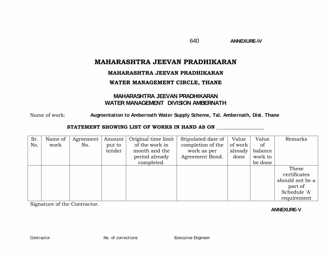
Contractor No. of corrections Executive Engineer
640 ANNEXURE-IV
MAHARASHTRA JEEVAN PRADHIKARAN MAHARASHTRA JEEVAN PRADHIKARAN
WATER MANAGEMENT CIRCLE, THANE
MAHARASHTRA JEEVAN PRADHIKARAN WATER MANAGEMENT DIVISION AMBERNATH
Name of work: Augmentation to Ambernath Water Supply Scheme, Tal. Ambernath, Dist. Thane
STATEMENT SHOWING LIST OF WORKS IN HAND AS ON ___________________ Sr. No.
Name of work
Agreement No.
Amount put to tender
Original time limit of the work in month and the period already
completed.
Stipulated date of completion of the
work as per Agreement Bond.
Value of work already done
Value of
balance work to be done
Remarks
These certificates
should not be a part of
Schedule 'A' requirement
Signature of the Contractor. ANNEXURE-V
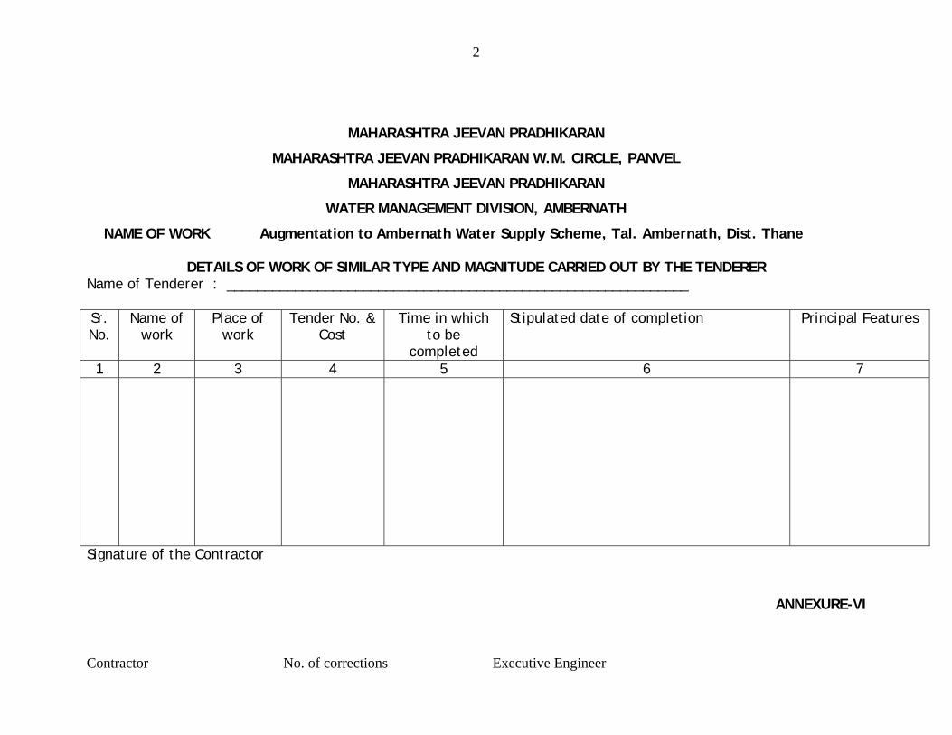
2
Contractor No. of corrections Executive Engineer
MAHARASHTRA JEEVAN PRADHIKARAN
MAHARASHTRA JEEVAN PRADHIKARAN W.M. CIRCLE, PANVEL
MAHARASHTRA JEEVAN PRADHIKARAN
WATER MANAGEMENT DIVISION, AMBERNATH
NAME OF WORK Augmentation to Ambernath Water Supply Scheme, Tal. Ambernath, Dist. Thane
DETAILS OF WORK OF SIMILAR TYPE AND MAGNITUDE CARRIED OUT BY THE TENDERER Name of Tenderer : _____________________________________________________________ Sr. No.
Name of work
Place of work
Tender No. & Cost
Time in which to be
completed
Stipulated date of completion Principal Features
1 2 3 4 5 6 7
Signature of the Contractor
ANNEXURE-VI
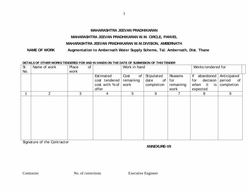
3
Contractor No. of corrections Executive Engineer
MAHARASHTRA JEEVAN PRADHIKARAN
MAHARASHTRA JEEVAN PRADHIKARAN W.M. CIRCLE, PANVEL
MAHARASHTRA JEEVAN PRADHIKARAN W.M.DIVISION, AMBERNATH
NAME OF WORK Augmentation to Ambernath Water Supply Scheme, Tal. Ambernath, Dist. Thane DETAILS OF OTHER WORKS TENDERED FOR AND IN HANDS ON THE DATE OF SUBMISSION OF THIS TENDER Sr.No.
Name of work Place of work
Work in hand Works tendered for
Estimated cost tendered cost with % of offer
Cost of remaining work
Stipulated date of completion
Reasons for remaining work
If abandoned for decision when it is expected
Anticipated period of completion
1 2 3 4 5 6 7 8 9
Signature of the Contractor ANNEXURE-VII

4
Contractor No. of corrections Executive Engineer
MAHARASHTRA JEEVAN PRADHIKARAN
MAHARASHTRA JEEVAN PRADHIKARAN W.M. CIRCLE, PANVEL
MAHARASHTRA JEEVAN PRADHIKARAN
WATER MANAGEMENT DIVISION, AMBERNATH
NAME OF WORK Augmentation to Ambernath Water Supply Scheme, Tal. Ambernath, Dist. Thane
STATEMENT SHOWING TECHNICAL PERSONNEL AVAILABLE WITH THE CONTRACTOR
Sr. No.
Designation Name Qualification Professional experience of work carried out by the
tenderer
Remarks
1 2 3 4 5 6
Signature of the Contractor
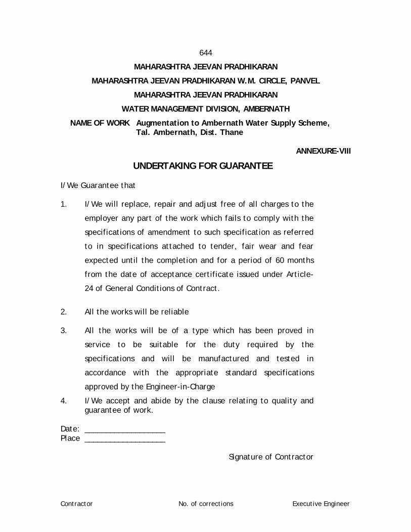
Contractor No. of corrections Executive Engineer
644
MAHARASHTRA JEEVAN PRADHIKARAN
MAHARASHTRA JEEVAN PRADHIKARAN W.M. CIRCLE, PANVEL
MAHARASHTRA JEEVAN PRADHIKARAN
WATER MANAGEMENT DIVISION, AMBERNATH
NAME OF WORK Augmentation to Ambernath Water Supply Scheme, Tal. Ambernath, Dist. Thane
ANNEXURE-VIII
UNDERTAKING FOR GUARANTEE I/We Guarantee that 1. I/We will replace, repair and adjust free of all charges to the
employer any part of the work which fails to comply with the
specifications of amendment to such specification as referred
to in specifications attached to tender, fair wear and fear
expected until the completion and for a period of 60 months
from the date of acceptance certificate issued under Article-
24 of General Conditions of Contract.
2. All the works will be reliable 3. All the works will be of a type which has been proved in
service to be suitable for the duty required by the
specifications and will be manufactured and tested in
accordance with the appropriate standard specifications
approved by the Engineer-in-Charge
4. I/We accept and abide by the clause relating to quality and guarantee of work.
Date: ___________________ Place ___________________
Signature of Contractor
2
Contractor No. of corrections Executive Engineer
645
MAHARASHTRA JEEVAN PRADHIKARAN
MAHARASHTRA JEEVAN PRADHIKARAN W.M. CIRCLE, PANVEL
MAHARASHTRA JEEVAN PRADHIKARAN
WATER MANAGEMENT DIVISION, AMBERNATH
NAME OF WORK Augmentation to Ambernath Water Supply Scheme, Tal. Ambernath, Dist. Thane
ANNEXURE -IX
DECLARATION OF THE CONTRACTOR
1. I /We ------------------------------------------------------------------------------------
Contractor(s) hereby undertake that I/We shall pay the laborers engaged on
the work as indicated in Scope of work, wages as per Minimum Wages Act,
1948 and amendments thereto applicable to the zone in which work lies and
act accordingly. I/We also undertake to abide by the various laws in force
and extend necessary facilities and amenities to the staff and workers
employed by me/us.
2. I/We hereby declare that I/We have made myself/ourselves thoroughly
conversant with the local conditions regarding all materials and labour on
which I/We have bidded my/our rates for this work. The specifications of
this work have been carefully studied and understood by me/us before
submitting this tender.
3. I/We hereby undertake to indemnify and hereby indemnify the MJP
against all liabilities arising out of application of all labour laws viz. the
Minimum Wages Act, the Workmen Compensation Act, the Payment Wages
Act, ESIS and Provident Fund Act etc. the reference to labour engaged on
subject work.
Signature of the Contractor
3
Contractor No. of corrections Executive Engineer
646
MAHARASHTRA JEEVAN PRADHIKARAN W.M. CIRCLE, PANVEL
MAHARASHTRA JEEVAN PRADHIKARAN
WATER MANAGEMENT DIVISION, AMBERNATH
NAME OF WORK Augmentation to Ambernath Water Supply Scheme, Tal. Ambernath, Dist. Thane
ANNEXURE - X MODEL FORM OF BANK GUARANTEE BOND
GUARANTEE BOND :
1. This deed of Guarantee is made on the by having his head office at
(hereinafter called the 'said Contractor(s)) from the demand under the terms
and conditions of Agreement dated made between and for (hereinafter
called 'the Agreement') of additional security deposit for the due fulfillment
by the said Contractors of the terms and conditions contained in the said
Agreement on production of a Bank Guarantee for `_____________ (` -------
-----------------only). We (hereinafter referred to as “the Bank") at the
request of (contractor) do hereby undertake to pay to the Maharashtra
Jeevan Pradhikaran (hereinafter as MJP) an amount not exceeding Rs. ---
---------- against any loss or damage caused to or suffered by the MJP by
reasons of any breach by the said contractor of any of the terms or
conditions contained in the said Agreement.
2. We ………………………………………………………(indicate the name of bank) do
hereby undertake to pay the amount due and payable under this guarantee
without any demur, merely on a demand from the MJP stating that the
amount claimed is due, by way of loss or damage caused to or would be
caused to or suffered by the MJP by reason of breach by the said
Contractor(s) of any of the terms of conditions contained in the said
Agreement or by reason of the contractor(s) failure to perform the said
agreement. Any such demand made on the bank shall be conclusive as
4
Contractor No. of corrections Executive Engineer
647
regards the amount due and payable under this guarantee shall be restricted
to an amount not exceeding ` ----------------.
3. We undertake to pay the MJP any money so demanded not
withstanding any dispute raised by the contractor(s)/ supplier(s) in any suit
or proceeding pending before any court or tribunal relating thereto, our
liability under this present being absolute and unequivocal. The payment so
made by us under this bond shall be valid discharge of our liability for
payment there under and the contractor(s)/ supplier(s) shall have no claim
against us for making such payment.
4. We…………………………………………(indicate the name of bank) further
agree that the guarantee herein contained shall remain in full force and
effect during the period that would be taken for performance of the said
Agreement and that it shall continue to be forcible till all the dues of the
MJP under or by virtue of the said Agreement have been fully paid and its
claims satisfied or discharged or till (MJP) of (indicate the name of
Administrative Officer) certifies that terms and conditions of the said
Agreement have been fully and properly carried out by the said
Contractor(s) and accordingly discharges this guarantee. Unless a demand or
claim under this guarantee is made on us in writing on or before the we
shall be discharged from all liability under this guarantee thereafter
5. ............... We, ………………………………………………………. (indicate the
name of bank) further agree with the MJP that the MJP shall have the
fullest liberty without our consent and without affecting in any manner our
obligations hereunder to vary any of the terms and conditions of the said
Agreement or to extend time of performance by the said contractor(s)from

5
Contractor No. of corrections Executive Engineer
time to time or postpone for any time or from time to time any of the
powers exercisable by the MJP against the said Contractor(s), and to forbear
648
or enforce any of the terms and conditions relating to the said Agreement,
and we shall not to be relieved from our liability by reason of such variation,
or extension being granted to the said contractor(s) or for any forbearance
act or omission on the part of the MJP or any indulgence by the MJP to the
said Contractor(s) or by any such matter or thing whatsoever which under
the law relating to surety would, but for this provision, have effect of so
relieving us.
6. This guarantee will not be discharged due to the change in the
constitution of the bank or the change in the constitution of the
contractor(s)/ suppliers.
7. ................. We …………………………….(indicate the name of the bank)
lastly undertake not to revoke this guarantee during its currency except with
the previous consent of the MJP in writing.
Dated the …………... day of …………2012 For …………….. (indicate the name of bank)

6
Contractor No. of corrections Executive Engineer
649 MAHARASHTRA JEEVAN PRADHIKARAN W.M. CIRCLE, PANVEL
MAHARASHTRA JEEVAN PRADHIKARAN
WATER MANAGEMENT DIVISION, AMBERNATH
NAME OF WORK Augmentation to Ambernath Water Supply Scheme, Tal. Ambernath, Dist. Thane
ANNEXURE – XI PROFESSIONAL TAX CLEARANCE CERTIFICATE
This is to certify that M/s ………………………………………………………………..…………..… of
(address) …………………………………………………………………….……………….………. is a
registered under the Maharashtra State Tax of Professions, Trades, Callings and
Employment Act XVI of 1975, holding Registration Certification
No………………….……………………w.e.f.
The said dealer has paid all taxes dues upto 31st March …………(previous
year) under the Act. The dealer has paid the professional tax dues for the
employees mentioned below
A. Sr No. Name of Employee Designation
B. Sr No. Name of Owner Carrying on Profession status Designation
There is no professional Tax dues outstanding against the dealer under
the Act. This certificate is valid for ONE year from the date of issue. Place : Date :
Signature ……………………………… Professional Tax Officer
7
Contractor No. of Corrections Executive Engineer
650 MAHARASHTRA JEEVAN PRADHIKARAN W.M. CIRCLE, PANVEL
MAHARASHTRA JEEVAN PRADHIKARAN
WATER MANAGEMENT DIVISION, AMBERNATH
NAME OF WORK Augmentation to Ambernath Water Supply Scheme, Tal. Ambernath, Dist. Thane
ANNEXURE – XII
AGREEMENT Article of agreement executed on this the…………………………………………of Two
Thousand ……………………..…………between the Executive Engineer, MJP
(hereinafter referred to as MJP of the one part and shri
……………………………………………… (Name and address of the tenderer)(hereinafter
referred to as 'the bounties1) of the other part.
Whereas in response to the notification No …………..dated……….……………the
bounden has submitted to the MJP a tender for the work specified therein
subject to the terms and conditions contained in the said tender.
Whereas the bounden has also deposited with MJP a sum of
RS.………..…………as earnest money for execution of an agreement undertaking
the due fulfillment of the contract in case his tender is accepted by the MJP.
Now these presents witness and it is mutually agreed as follows : 1) In case the tender submitted by the bounden is accepted by the MJP
and the contract for is awarded to the bounden, the bounden shall within ……………….. days of acceptance of his tender execute an agreement with MJP incorporating all the terms and conditions under which he accepts his tender.
2) In case the bounden fails to execute the agreement as aforesaid incorporating terms and conditions governing the contract, the MJP shall have power and authority to recover from the bounden any loss or any damage caused to the MJP by such breach, as may be determined by the MJP, by appropriating the earnest money deposited by the bounden and if the earnest money is found to be inadequate the deficit amount may be recovered from the bounden and his properties, movable and immovable, in the manner hereafter contained.
8
Contractor No. of Corrections Executive Engineer
651
3) All sums found due to the MJP under or by virtue of this agreement shall be recoverable from the bounden and his properties, movable and immovable, under the provisions of the Maharashtra Land Revenue Code for the time being in force as though such sums are arrears of the land revenue and in such other manner as the MJP may deem fit.
In witness where of shri………………………………………………………..(Name and
designation) for and on behalf of the MJP and Shri…………………………………… The
bounden have hereunto set their hands the days and year shown against their
respective signature.
Signed by Shri…………………….…………………… Date : ………….In the presence of witness 1 ……………………………………………………… 2……………………………………..… Signed by Shri ……………………………… ……………… Date ……… Witness 1 ……………………………………………………..… 2 ………………………………………………………..
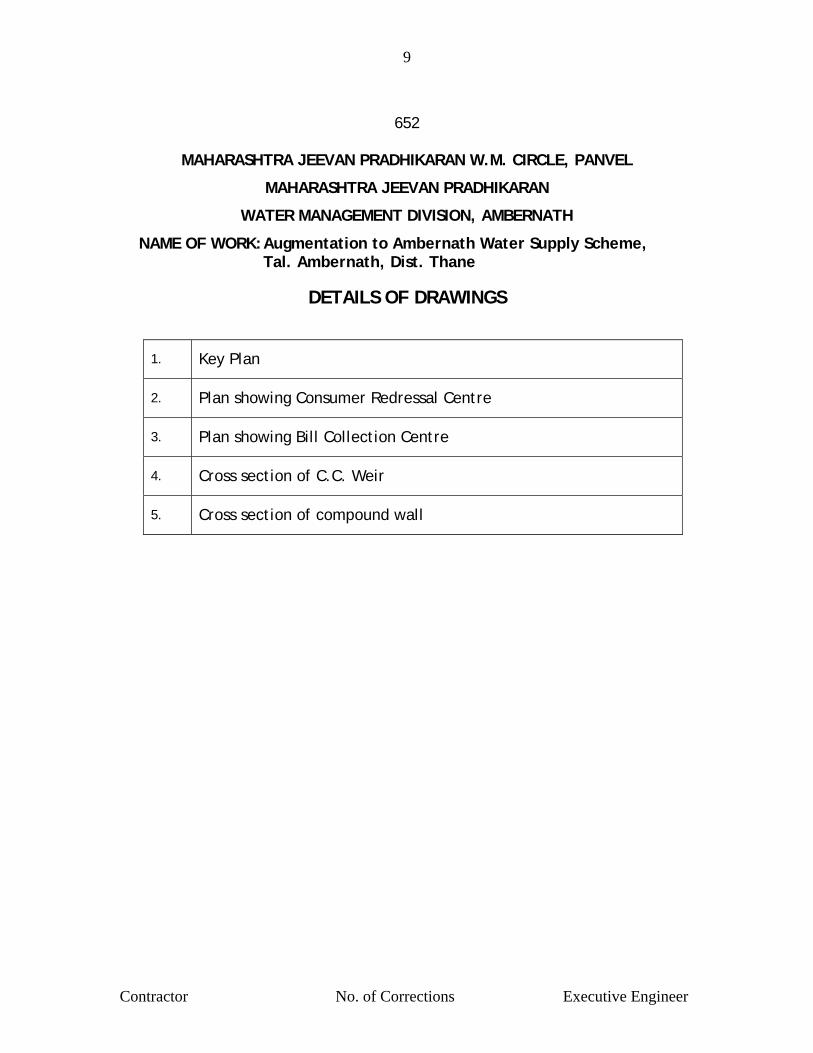
9
Contractor No. of Corrections Executive Engineer
652
MAHARASHTRA JEEVAN PRADHIKARAN W.M. CIRCLE, PANVEL
MAHARASHTRA JEEVAN PRADHIKARAN
WATER MANAGEMENT DIVISION, AMBERNATH
NAME OF WORK: Augmentation to Ambernath Water Supply Scheme, Tal. Ambernath, Dist. Thane
DETAILS OF DRAWINGS
1. Key Plan
2. Plan showing Consumer Redressal Centre
3. Plan showing Bill Collection Centre
4. Cross section of C.C. Weir
5. Cross section of compound wall

ORDNANCEFACTORY SUMP
210 M
PROPOSED SUMP &
PUMP HOUSE CAP ( ML ) : 0.35NEW M. B. R. BELAVALI
700 MM DIA C.IR / MAN
ULHAS RIVER
BHENDIPADABOOSTER SUMP
400 Ï DIK7 300 M
600 Ï DI L=300 M
600MM DI K-9 L=1400 M
600 MM DIA CI GM
KALYAN - BADLAPUR ROAD
750 MM DIA DI L=2000 M
KALYAN
KALYAN AMB STATION
350 MM DIA DI L= 1150M
CAP ( ML ) : 1.50
SAI SECTION
E.S.R
G. S. R. CAP ( ML ) : 1.10
300 MM DIA DI K- 7 L-1200M
200 MM DIA DI K - 7 L= 2000 M
NAVARE NAGARE.S.R. CAP-2 ML
355 DIAM.S.R.M.
100 MLDJACKWELL &PUMP HOUSE
700 MM DIA C.I. TRANS MAIN
NALA
ULHAS RIVER
CHIKHLOLI MI - TANK
BADLAPUR STN.
PUNE
EXISTING WORK SHOWN THUS
OLDM.B.R
SUMP
50MLDBARRAGEH/WORK
MAHARASHTRA JEEVAN PRADHIKARANWATER MANAGEMENT DIV. AMBERNATH
LAYOUT PLANAUG.TO AMBERNATH W.S.SCHEME
N
WTP 18MLD
WTP 7.2 MLD
CAP ( ML ) : 2.00F. S. L. : 80.00L. W. L. : 75.00G. L. : 55.00 500 M
M DIA DI K- 9 L-4000M
300 MM DIA
CAP ( ML ) : 2.00
E.S.R.CAP ( ML ) : 1.50F. S. L. : 15.70L. W. L. : 12.70G. L. : 15.20
CAP ( ML ) : 2.0 X2F. S. L. : 67.00L. W. L. : 62.00G. L. : 45.00
AMB.BOOSTER
NARAYAN NAGAR PROPOSED BHENDIPADA
CAP-1.50 ML.
BHENDIPAD G.S.R.CAP-0.90 X 3 (EXISTING)
CAP ( ML ) :1.50F. S. L. : 74.00L. W. L. : 70.00G. L. : 55.00
CAP ( ML ) : 2.00F. S. L. : 30.50L. W. L. : 28.00G. L. :30.00
CAP ( ML ) : 6.80F. S. L. : 66.90L. W. L. : 62.30G. L. : 62.30 CAP ( ML ) :13.63
F. S. L. : 66.87L. W. L. : 62.30G. L. : 62.30
711 MM DIA M.S. R/ MAIN
R.D.BHERE, TRACER AMB. SUB.DIV.
PROPOSED E.S.R.
PROPOSED WORK SHOWN THUS
BADLAPU VILLAGE
YER
ANJA
D U
NGAT
EDR.
C.C.
WEI
R
400 Ï DIK7
CAP ( ML ) : 2.70G.L. :56.90L. S. L. : 56.90F.S.L. : 62.00
DISTRIBUTION
DISTRIBUTION
DISTRIBUTION
DISTRIBUTION
DISTRIBUTION
DISTRIBUTION
L.S.L :40.00 F.S.L. :45.00G. L. :23.00
MIDC ROADTAPPING FORAMBERNATH
TO BADLAPUR
CAP ( ML ) : 0.25F. S. L. : 69.00L. W. L. : 66.00G. L. : 56.00
CAP ( ML ) : 0.85F. S. L. : 23.50L. W. L. : 21.00G. L. : 23.00
CAP ( ML ) : 1.50F. S. L. :47.00L. W. L. : 43.00G. L. : 28.00
CAP ( ML ) : 1.50F. S. L. : 62.00L. W. L. : 57.0G. L. : 42.00
MIDC BARVI MAIN
MIDC B
ARVI MAIN
100 MM DIA D.I.K-9 L=1000 M.
SUMPG.L. :48.00L.S.L. :38.00F.S.L. :44.00
DAM STORAGE : 80.80H.F.L. : 59.935F.S.L. : 58.435L.S.L. : 44.935
DEAD STORAGE : 12.70 MCFT LIVE STORAGE : 68.10 MCFT
SECT.ENG. S.D.E. EX.ENG. S.E.
700 MM Ï DI K-9 L-500 MAMBERNATHGAON
E.S.R
SHIVGANGANAGARE.S.R
E.S.R
400 MM Ï DI.K-7SUMP 0.27 ML
400 MM Ï DIK-7 L=900 M
TO ORDINANCE
500 MM Ï DI K-7 L=1650 M
POLICEGROUND
L=50 M
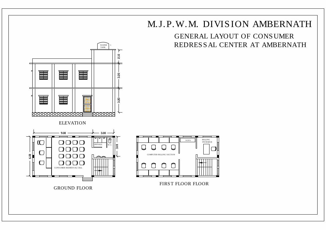
GROUND FLOORFIRST FLOOR FLOOR
ELEVATION
CONSUMER REDRESSAL CELL
COMPUTER BILLING SECTION
BILLINGINCHARGE
SOFA
URINALS W.C.
WATERTANK
M.J.P.W.M. DIVISION AMBERNATHGENERAL LAYOUT OF CONSUMERREDRESSAL CENTER AT AMBERNATH


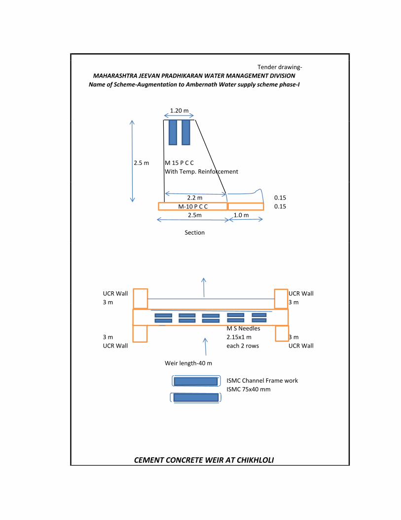
Tender drawing‐
1.20 m
MAHARASHTRA JEEVAN PRADHIKARAN WATER MANAGEMENT DIVISIONName of Scheme‐Augmentation to Ambernath Water supply scheme phase‐I
2.5 m M 15 P C CWith Temp. Reinforcement
0.150.15
1.0 m
2.2 m
Section
2.5mM‐10 P C C
UCR Wall UCR Wall3 m 3 m3 m 3 m
M S Needles3 m 2.15x1 m 3 mUCR Wall each 2 rows UCR Wall
Weir length‐40 mWeir length 40 m
ISMC Channel Frame workISMC 75x40 mm
CEMENT CONCRETE WEIR AT CHIKHLOLI

Tender drawing‐
0.10 m M‐150 Coping
0 23 B i k Pill
MAHARASHTRA JEEVAN PRADHIKARAN WATER MANAGEMENT DIVISION AMBERNATHName of Scheme-Augmentation to Ambernath Water supply scheme phase-I
0.23 Brick Pillar
1.30 m Brick masonary CM 1:6cement plaster C M 1:3
0.10 m M‐150 Coping
Tuck Pointing CM 1:3 0.45 0.45 m U C R Masonary C M 1:6G L
0.75 m 0.6 m 0.60 m
0 15 m PCC M‐1000.15 m PCC M‐1000.90 m
Drawing showing section of compound wall work
![Screen Shot-Jeevan Pramaan Shot-Jeevan Pramaan.pdfC] Report:: CSC India Report X Jeevan Pramaan "Deity ' X JEEvan Pramaan C cscstaging.e-kyc.in/jeevanpramaan/frmEnrolment.aspx Jeevan](https://img.pdfslide.us/doc/110x75/5f10e16b7e708231d44b425f/screen-shot-jeevan-shot-jeevan-pramaanpdf-c-report-csc-india-report-x-jeevan.jpg)