Embed Size (px)
Citation preview

(NASA-CB-165452-Vol-2) HAGHETOHYDBODYNAJ3ICS N82-21837(MHD) ENGINEEBING TEST FACILITY (ETF) 200HWe POWER PLAMT. CONCEPTUAL DESIGNENGINEEBING BEPOHT (CDER) . VC1UME 2: OnclasENGINEERING. VOLUME (Gilbert/Commonwealth) G3/44 28248
DOE/NASA/0224-1NASA CR-165452 - Volumes ll-lll
Magnetohydrodynamics (MHD)Engineering Test Facility (ETF)200 MWe Power Plant
Conceptual Design Engineering Report (CDER)
Volume II — EngineeringVolume III — Costs and Schedules(Included as Microfiche)
Gilbert / CommonwealthEngineers / Consultants
September 1981
Prepared forNational Aeronautics and Space AdministrationLewis Research CenterUnder Contract DEN 3-224
forU.S. DEPARTMENT OF ENERGYFossil EnergyOffice of Magnetohydrodynamics
https://ntrs.nasa.gov/search.jsp?R=19820019961 2020-06-13T17:56:22+00:00Z

NOTICE
This report was prepared to document work sponsored by the United StatesGovernment Neither the United States nor its agent, the United States Department ofEnergy, nor any Federal employees, nor any of their contractors, subcontractors or theiremployees, makes any warranty, express or implied, or assumes any legal liability orresponsibility for the accuracy, completeness, or usefulness of any information,apparatus, product or process disclosed, or represents that its use would not infringeprivately owned rights.
DOE/NASA/0224-1NASA CFM65452 - Volumes II-
Magnetohydrodynamics (MHD)Engineering Test Facility (ETF)200 MWe Power Plant
Conceptual Design Engineering Report (CDER)
Volume II — EngineeringVolume III — Costs and Schedules(Included as Microfiche)
Gilbert / CommonwealthEngineers / ConsultantsReading, PA/Jackson, MlWashington, D.C.I Oak Ridge, TN
September 1981
Prepared forNational Aeronautics and Space AdministrationLewis Research CenterCleveland, Ohio 44135Under Contract DEN 3-224
forU.S. DEPARTMENT OF ENERGYFossil EnergyOffice of MagnetohydrodynamicsWashington, D.C. 20545Under Interagency Agreement DE-AI01-77ET10769

"PAGE MISSING FROM AVAILABLE VERSION"
PRECEDING PAGE BLANK NOT FILMED
MHD-ETF•CONCEPTUAL DESIGNENGINEERING REPORT
TABLE OF CONTENTS
Section Title
VOLUME I
1.0
1.1
1.2
1.3
1.3.11.3.21.3-31.3.3.11.3.3.21.3.3.31.3,3.41.3.3-51.3.3.61.3.3.71.3.3.81.3.3.91.3.3.10
1.3.4.11.3-4.21.3-4.31.3.4.41.3-4.51.3.4.61.3.51.3-61.3.7
1.4
1.4.11.4.21.4.3
1.5
1.6
- EXECUTIVE SUMMARY
EXECUTIVE SUMMARY
PURPOSE
SCOPE
SUMMARY DESCRIPTION OF ETF
Design Criteria and SummaryPlant PerformancePlant Facilities Description
MHD BuildingTurbine Generator BuildingHR/SR BuildingAir and Oxidant Compressor BuildingInverter BuildingControl ComplexAdministration and Service BuildingCoal Handling and PreparationCooling Towers"Other Facilities
System DescriptionsOxidant SupplyMHD Power TrainMagnetHeat Recovery/Seed RecoverySteam Power SystemAuxiliary Systems
Plant ServicesPerformance Assurance Program PlanEnvironmental Analysis Study
PLANT COSTS
Costing Procedure and BasesPrincipal Account ValuesConfidence Levels
SCHEDULES
ISSUES
1-1
1-5
1-7
1-9
1-91-111-131-131-181-181-181-181-181-181-181-191-191-191-191-191-201-201-231-241-261-281-29
1-31
1-311-311-31
1-33
1-35
ill
TABLE OF CONTENTS (Cont'd)
Section Title
VOLUME II - ENGINEERING
2.0 ENGINEERING SUMMARY 2-1
2.1 PLANT FACILITIES AND FUNCTIONAL DESCRIPTION 2-3
2.1.1 Major Structures and Site Facilities 2-32.1.1.1 MHD Building 2-32.1.1.2 Turbine Generator Building 2-32.1.1.3 Heat Recovery/Seed Recovery
HR/SR Building 2-32.1.1.4 Air and Oxidant Compressor Building 2-32.1.1.5 Inverter Building 2-32.1.1.6 Administration and Service Building 2-32.1.1.7 Yard Coal Handling 2-32.1.1.8 Yard Seed Handling 2-42.1.1.9 Cooling Towers 2-42.1.1.10 Miscellaneous Buildings and Structures 2-42.1.2 Power Subsystems and Their Functions 2-42.1.2.1 Oxidant Supply 2-42.1.2.2 MHD Power Train 2-52.1.2.3 Magnet 2-62.1.2.4 Heat Recovery/Seed Recovery System 2-72.1.2.5 Steam Power Systems 2-102.1.2.6 Plant Auxiliary Systems 2-102.1.2.7 Plant Services 2-112.1.3 Plant Operating Characteristics 2-11
2.2 DESIGN REQUIREMENTS AND CRITERIA 2-13
2.2.1 Operational Objectives 2-132.2.2 Input Parameters 2-132.2.3 Design Requirements 2-14
2.3 SYSTEM HEAT AND MASS FLOW BALANCE 2-15
2.4 MHD PRINCIPLES AND TERMINOLOGY 2-17
2.4.1 MHD Principles 2-172.4.2 MHD System Terminology 2-192.4.2.1 MHD Generator 2-192.4.2.2 MHD Channel 2-192.4.2.3 Plasma 2-192.4.2.4 Pressure Ratio 2-19
IV
TABLE OF CONTENTS (Cont'd)
Section
VOLUME II -
2.4.2.52.4.2.62.4.2.72.4.2.82.4.2.92.4.2.102.4.2.112.4.2.122.4.2.132.4.2.14
2.5
2.5.12.5.1.12.5.1.22.5.1.32.5.22.5.2.12.5.2.1.12.5.2.1.22.5.2.1.32.5.2.1.42.5.2.22.5.2.2.12.5.2.2.22.5.2.2.32.5.2.32.5.2.42.5.32.5.3-12.5.3.22.5.3-32.5.3.42.5.3.52.5.42.5.4.12.5.4.22.5.4.32.5.4.42.5.4.52.5.4.62.5.52.5.5.1
Title
(Cont'd)
Enthalpy ExtractionChannel LoftingFaraday VoltageHall ParameterHall VoltageActive LengthDiagonal ConnectionDiagonal MHD GeneratorConsolidationCore and Boundary Layer
PLANT DETAILED DESCRIPTION
Oxidant SupplyAir Separation Unit (ASU)ASU Compressor and AuxiliariesOxidant Preparation
MHD Power TrainCombustor SubsystemCombustion ChamberPlasma DuctNozzleSlag Removal EquipmentMHD Generator Subsystem'MHD ChannelConsolidation CircuitryDiffuserInverter SubsystemMHD Control Subsystem
MagnetMagnet AssemblyCryogenic Support EquipmentPower Supply and Dump EquipmentProtection/Control CircuitVacuum Pumping Equipment
Heat Recovery/Seed Recovery (HR/SR)BoilerSuperheaterReheaterOxidant HeaterHigh Temperature EconomizerElectrostatic Precipitator (ESP)
Steam Power SystemsMain and Reheat Steam
2-202-202-202-202-202-202-202-202-202-21
2-23
2-252-252-272-292-332-332-352-352-352-352-352-372-382-382-382-392-412-432-452-462-462-472-492-492-492-512-512-512-512-532-53

TABLE OF CONTENTS (Cont'd)
Section Title
VOLUME II - (Cont'd)
2.5.5.1.12.5.5.1.22.5.5.1.32.5.5.22.5.5.32.5.5.42.5.5.4.12.5.5. .22.5.5.4.32.5.5.52.5.5.5.12.5.5.5.22.5.5.5.32.5.5.62.5.5.7
2.5.5.82.5.5.92.5.62.5.6.12.5.6.22.5.6.32.5.6.3.12.5.6.3.22.5.6.U2.5.6.4.12.5.6.4.22.5.6.4.32.5.6.4.42.5.6.52.5.6.62.5.6.6.12.5.6.6.22.5.6.6.3
2.5.6.6.4
2.5.6.6.5
2.5.6.6.6
2.5.6.6.72.5.6.6.82.5.6.6.9
Flow DescriptionMajor EquipmentModes of Operation
Steam Bypass and StartupExtraction SteamCondensate
Flow DescriptionMajor EquipmentModes of Operation
Boiler FeedwaterFlow DescriptionMajor EquipmentModes of Operation
Feedwater Heater DripsFeedwater Heater and Miscellaneous Drains,Vents and Reliefs
Condenser Air RemovalCirculating Water
Plant Auxiliary SystemsAuxiliary SteamBoiler Flue Gas SystemCoal Management
Yard Coal HandlingCoal Feed -Lock Hoppers
Seed ManagementYard Seed HandlingSeed Feed Lock HoppersAsh/Seed Removal from Power SystemSeed Recycle
Slag ManagementElectrical
Switchyard- 138 kVInverter Bus Step-Up TransformerTurbine-Generator and T-G Step-UpTransformer
Oxidant Compressor Transformand Motor
MHD and T-G Station ServiceTransformers
Main MHD and T-G 4.16 kV MetalClad Switchgear
Critical Metal Clad SwitchgearMedium Voltage 4.16 kV Starters480 V Load Center
2-532-532-552-562-572-572-572-582-592-612-612-612-622-64
2-652-652-652-672-672-672-682-682-712-712-712-722-722-732-732-732-742-74
2-74
2-74
2-75
2-752-752-752-75
vi

TABLE OF CONTENTS (Cont'd)
Section Title
VOLUME II - (Cont'd)
2.5.6.6.10 480 V Cooling Tower Load Center 2-752.5.6.6.11 Coal Management Load Center and
4.16 kV Starter 2-752.5.6.6.12 Thaw Shed 480 V Load Centers (4) 2-752.5.6.6.13 Critical 480 V Load Center 2-762.5.6.6.14 Uninterruptible Power Supply (UPS)
Systems 2-762.5.6.6.15 Plant do Systems 2-762.5.7 Plant Services 2-772.5.7.1 Closed Cycle Cooling Water System (CCCWS) 2-772.5.7.2 Plant Makeup Water 2-772.5.7.3 Sampling 2-782.5.7.4 Industrial Gas Systems 2-792.5.7.4.1 Plant Service Air and Instrument
Air Supply System 2-792.5.7.4.2 Miscellaneous Gases 2-792.5.7.5 Fuel Oil System 2-792.5.7.6 ' Plant Industrial Waste 2-802.5.7.6.1 Coal Pile Runoff (CPR) 2-802.5.7.6.2 Chimney Wash and Air Heater Wash 2-802.5.7.6.3 Demineralizer Regenerative Waste 2-802.5.7.6.4 Building Drains 2-812.5.7.6.5 Wastewater Treatment 2-812.5.7.6.6 Fuel Oil Unloading and Storage Area
Runoff 2-812.5.7.6.7 Plant Yard Drainage 2-812.5.7.6.8 Sanitary Wastes 2-812.5.7.7 Fire Service Water 2-822.5.7.8 Domestic Services 2-822.5.7.8.1 Potable Water 2-832.5.7.9 Heating, Ventilating,and Air Conditioning 2-832.5.8 Facilities 2-852.5.8.1 Yard Coal Handling . 2-852.5.8.2 Yard Seed Handling 2-852.5.8.3 MHD Building 2-852.5.8.4 Turbine Generator Building 2-862.5.8.5 Administration and Service Building 2-862.5.8.6 Control Complex 2-662.5.8.7 Cooling Towers 2-862.5.8.8 Miscellaneous Buildings and Structures 2-87
vii
TABLE OF CONTENTS (Cont'd)
Section
VOLUME II - (Cont'd)
Title
2.6
2.6.12.6.1.12.6.1.22.6.22.6.32.6.42.6.5
2.7
2.7.12.7.22.7.2.1
2.7.2.22.7.2.32.7.32.7.3.12.7.3-2
2.8
2.8.12.8.2
PLANT OPERATING MODES
StartupInitialOperational
BaseloadTransientShutdownMalfunction Procedures
MAINTENANCE, LOGISTICS, AND SECURITY
LogisticsMaintenance and Replacement
Design Features and PreventativeMaintenance
Routine and Operational MaintenanceShutdown Maintenance Schedules
SecurityPersonnel AccessInternal Secure Areas
DRAWINGS
Heat and Mass Balance DiagramGAI Drawing List
Page
2-89
2-892-892-902-932-962-962-97
2-99
2-992-100
2-1002-1012-1032-1032-1032-104
2-105
2-1052-105
APPENDIX 2A
APPENDIX 2B
APPENDIX 2C
HEAT AND MASS BALANCE DIAGRAM
GAI DRAWING LIST
RELATED DRAWINGS
2-107
2-111
2-113
VOLUME III - COSTS AND SCHEDULES*
3.0
3.1
3.1.13.1.2
COSTS
COSTING PROCEDURE
Principal AccountsCost Parameters and Allotments
3-1
3-3
3-33-4
Included as microfiche in envelope at back of volume II,
viii

TABLE OF CONTENTS (Cont'd) •
Section Title Page
VOLUME III - (Cont'd)
3.2 COSTING BASES 3-73.2.1 Conversion Tables for Constant Dollars 3-73.2.2 Vendor Data 3-73.2.3 Reference Cost Data 3-83.2.4 Comparison with Analogous (Constructed)
Plant Subsystems 3-83.2.5 Judgement Factors 3-9
3.3 PRINCIPAL ACCOUNT VALUES 3-11
3.3.1 Material Cost and Balance of Account 3-113.3.2 Construction Costs 3-113.3.3 Contingency Assessment 3-163.3.4 Engineering and Other Costs 3-16
3.4 CONFIDENCE LEVELS 3-17
3.4.1 Major Uncertainties 3-173-4.2 Subsystem Cost Tolerances 3-173.4.3 Plant Cost Tolerances 3-17
APPENDIX 3A DOE/MHD GUIDELINES 3-19
PART A ETF COST ESTIMATE FORMAT 3-20«
PART B ETF CODE OF ACCOUNTS 3-23
4.0 SCHEDULES • 4-1
4.1 PRELIMINARY DESIGN (TITLE I) 4-3
4.1.1 Studies 4-34.1.1.1 Siting Considerations 4-34.1.1.2 Environmental Impact Analysis 4-114.1.1.3 Licensing Requirements 4-124.1.1.4 Vendor Selection 4-154.1.2 Engineering 4-154.1.2.1 Project Outline and Controls 4-154.1.2.2 Performance Assurance Program Plan 4-164.1.2.3 Bottoming Cycle Systems 4-164.1.2.4 MHD Systems 4-16

TABLE OF CONTENTS (Cont'd)
Section Title Page
VOLUME III - (Cont'd)
4.2 DEFINITIVE DESIGN (TITLE II) 4-19
4.2.1 Packages 4-194.2.2 Systems 4-194.2.2.1 Topping Cycle 4-194.2.2.2 Bottoming Cycle 4-244.2.2.3 Structures 4-24
4.3 PROCUREMENT, FABRICATION AND CONSTRUCTION 4-27
.4.3.1 Procurement 4-274.3.2 Fabrication and Construction 4-27
4.4 TESTING 4-33
4.5 OPERATIONS 4-37
4.5.1 Test Facility 4-374.5.2 Commercial Facility 4-37
SUMMARY 4-37
VOLUME IV - SUPPLEMENTARY ENGINEERING DATA
5.0 SUPPLEMENTARY ENGINEERING DATA 5-1
5.1 ISSUES 5-3
5.2 BACKGROUND DATA 5-5
5.2.1 Design Antecedents 5-75.2.2 Pertinent Studies 5-9
201(3) Evaluation of Electric MotorDrivers to Replace SteamTurbine Drivers
206(1) GAI Review of UTSI TopicalReport FE-10815-45 -"Evaluation of a Coriolis MassFlow Meter for PulverizedCoal Flows"
Section
VOLUME IV - (Cont'd)
TABLE OF CONTENTS (Cont'd)
Title Page
304 On-Site Integration of the RCC 'Modified Engel-Precht SeedReprocessing System Into ETF
305 Impact of New Magnetic Field Exclusionfor Personnel Access
306(1) Channel Replacement-ChannelDowntime and Its Effect on SystemAvailability
306(2) Channel Replacement - Arrangementand Evaluation of Alternatives
307 Regenerative Combustor Cooling
5.2.3
5.3
5.3.15.3.2
5.4
5.4.15.4.25.4.3
5.5
308(1) Operational Costs of the MHD-ETFfor the Commercial Phase
308(2) Pre-Operational Tests of the ETFTopping Side Components
Supplemental Data 5-11
OUTLINES OF PLANS IN SUPPORT OF THE CDER 5-13
MHD-ETF Performance Assurance (PA) Program Plan 5-15Plan for the Environmental Analysis Study forthe MHD-ETF 5-17
DESIGN DETAILS 5-19
Equipment List 5-19Electrical Load List 5-19Water Balance 5-19
SYSTEM DESIGN DESCRIPTIONS 5-21
System DesignDescription No.
SDD-011
031
System Design Description
MAIN & REHEAT STEAM(TURBINE-GENERATOR)
STEAM BYPASS & STARTUP
xi

TABLE OF CONTENTS (Cont'd)
Section Title
VOLUME IV - (Cont'd)
041 EXTRACTION STEAM051 AUXILIARY STEAM081 BOILER FEEDWATER101 • • CONDENSATE111 FEEDWATER HEATER DRIPS113 FEEDWATER HEATER & MISCELLANEOUS
DRAINS, VENTS & RELIEFS131 CONDENSER AIR REMOVAL161 PLANT MAKEUP WATER181 SAMPLING201 CIRCULATING WATER
VOLUME V - SUPPLEMENTARY ENGINEERING DATA (CONT'D
System DesignDescription No. System Design Description
231 CLOSED CYCLE COOLING WATER241 INDUSTRIAL GAS SYSTEMS281 FUEL OIL321 BOILER FLUE GAS341 COAL MANAGEMENT342 SEED MANAGEMENT351 SLAG MANAGEMENT371 PLANT INDUSTRIAL WASTE401 FIRE SERVICE WATER501 OXIDANT SUPPLY502 MHD POWER TRAIN503 MAGNET504 HEAT RECOVERY/SEED RECOVERY505 INVERTER701 HEATING, VENTILATING, AND
AIR CONDITIONING801 ELECTRICAL
xii
2.0 ENGINEERING SUMMARY
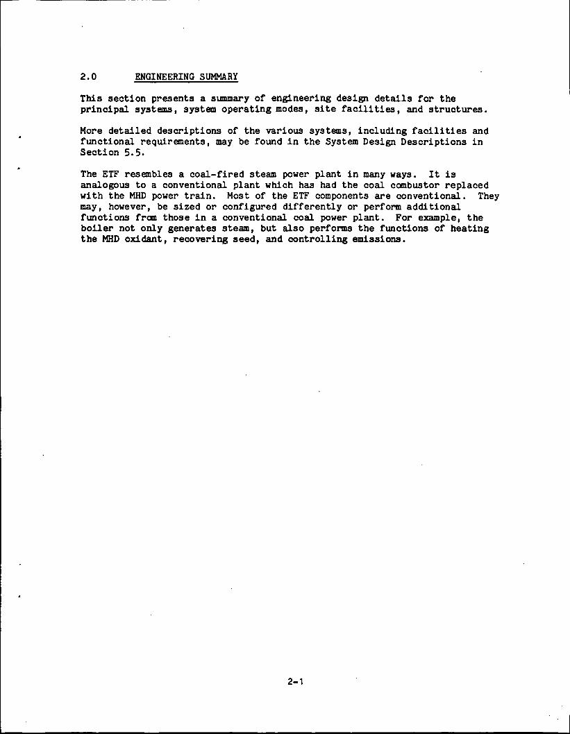
This section presents a summary of engineering design details for theprincipal systems, system operating modes, site facilities, and structures.
More detailed descriptions of the various systems, including facilities andfunctional requirements, may be found in the System Design Descriptions inSection 5.5.
The ETF resembles a coal-fired steam power plant in many ways. It isanalogous to a conventional plant which has had the coal combustor replacedwith the MHD power train. Most of the ETF components are conventional. Theymay, however, be sized or configured differently or perform additionalfunctions from those in a conventional coal power plant. For example, theboiler not only generates steam, but also performs the functions of heatingthe MHD oxidant, recovering seed, and controlling emissions.
2-1

PRECEDING PAGE BLANK NOT FILMED
2.1 PLANT FACILITIES AND FUNCTIONAL DESCRIPTION
2.1.1 Major Structures and Site Facilities
2.1.1.1 MHD Building
The MHD operating area contains the major MHD cycle components. Overalldimensions are 200 feet by 170 feet and the bay height is 100 feet. Specialfeatures include a combustor slag pit, a rail car and truck bay, a magnetarea, consolidation equipment, and a 150 ton capacity crane.
2.1.1.2 Turbine Generator Building
The turbine generator is located in a building with dimensions of 84 feet by168 feet with four elevations to a height of 92 feet. Included in thisstructure are the control complex and the heater bay. Servicing this complexis a railroad access bay and a 100 ton capacity crane.
2.1.1.3 Heat Recovery/Seed Recovery (HR/SR) Building
This building functions as an enclosure for the heat recovery equipment,namely, the radiant boiler, superheater, reheater, oxidant heater, andeconomizer. The HR/SR structure has eight elevations plus four intermediateplatforms occupying an area of 112 feet by 140 feet to a height of 153 feet.A radiant boiler slag pit extends 11 feet below grade.
2.1.1.4 Air and Oxidant Compressor Building
The ASU and Oxidant compressors are housed in a building to protect these highperformance machines from the weather. This building has two elevations andis 84 feet by 140 feet and 86 feet high. The building is adjacent to therailroad bay. A 40 ton capacity crane on a 84 foot span services this area.
2.1.1.5 Inverter Building
The inverter building, located adjacent to the MHD building, is 112 feet by168 feet and 35 feet high. This building encloses the inversion equipmentnecessary for converting the MHD generated power from direct current (dc) toalternating current (ac). An additional 22 foot wide enclosed bay at the endof the inverter building houses the ac switchgear.
2.1.1.6 Administration and Service Building
This building has two elevations and is 55 feet by 135 feet by 30 feet high.It contains the main machine shop, with a 20 ton capacity crane, and theauxiliary repair 'and maintenance bays.
2.1.1.7 Yard Coal Handling
Included in coal handling facilities are:
2-3

1. Coal Pile Storage - Each compacted pile is 200 feet by 500 feet and40 feet high. Each pile contains enough coal to operate at full load for30 days.
. * *
2. Thawing sheds, dumper building, dumper pit and coal crusher house.
3. Coal feed building and coal system control building.
4. Coal pile runoff collection pond, 110 feet by 250 feet and a finalcollection pond, 240 feet by 440 feet.
2.1.1.8 Yard Seed Handling
The seed handling facilities comprise the following:
1. Seed unloading hopper shed and storage silos.
2. Seed feed building.
3. Spent seed silos.
2.1.1.9 Cooling Towers
The cooling tower complex contains eight mechanical draft units and, with thecirculating water pumphouse, occupies an area of 140 feet by 145 feet.
2.1.1.10 Miscellaneous Buildings and Structures
Other significant plant features are:
1. Air Separation Unit Equipment Area (adjacent to compressor building)
2. Fuel Oil Tank, Dike and Pump House.
3. Main Guard House.
4. Substation.
2.1.2 Power Subsystems and Their Functions
2.1.2.1 Oxidant Supply
The Oxidant Supply System provides oxidant at the flow rate and pressurerequired for the operation of the MHD Power Train. An IntermediateTemperature Oxidant Heater (ITOH) of the HR/SR serves to preheat the oxidantto 1100°F prior to entering the MHD Power Train combustor.
A medium purity gaseous oxygen stream is produced in a cryogenic airseparation unit (ASU). This stream is blended with atmospheric air in amixing chamber to provide a stream with the required oxygen content. Theoxidant stream is compressed by two parallel uncooled axial compressors drivenby steam turbines.
2-4
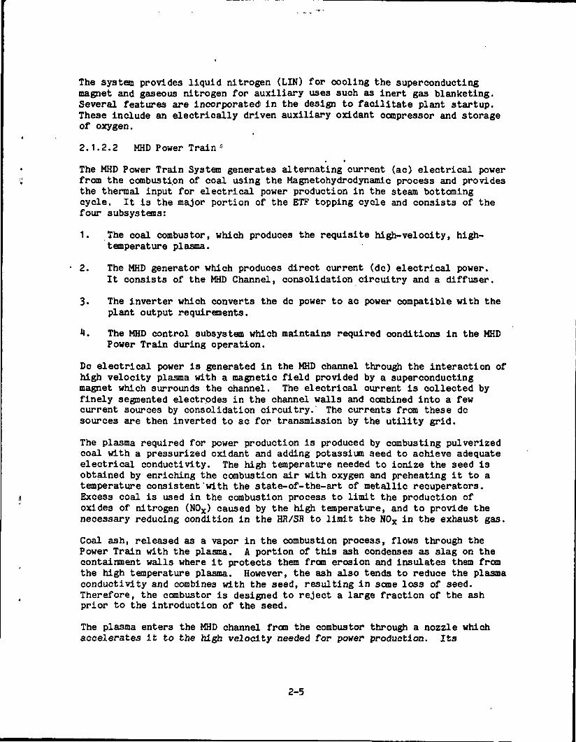
The system provides liquid nitrogen (LIN) for cooling the superconductingmagnet and gaseous nitrogen for auxiliary uses such as inert gas blanketing.Several features are incorporated in the design to facilitate plant startup.These include an electrically driven auxiliary oxidant compressor and storageof oxygen.
2.1.2.2 MHD Power Train f l
• k
The MHD Power Train System generates alternating current (ac) electrical powerfrom the combustion of coal using the Magnetohydrodynamic process and providesthe thermal input for electrical power production in the steam bottomingcycle. It is the major portion of the ETF topping cycle and consists of thefour subsystems:
1. The coal combustor, which produces the requisite high-velocity, high-temperature plasma.
2. The MHD generator which produces direct current (do) electrical power.It consists of the MHD Channel, consolidation circuitry and a diffuser.
3. The inverter which converts the dc power to ac power compatible with theplant output requirements.
4. The MHD control subsystem which maintains required conditions in the MHDPower Train during operation.
DC electrical power is generated in the MHD channel through the interaction ofhigh velocity plasma with a magnetic field provided by a superconductingmagnet which surrounds the channel. The electrical current is collected byfinely segmented electrodes in the channel walls and combined into a fewcurrent sources by consolidation circuitry. The currents from these dcsources are then inverted to ac for transmission by the utility grid.
The plasma required for power production is produced by combusting pulverizedcoal with a pressurized oxidant and adding potassium seed to achieve adequateelectrical conductivity. The high temperature needed to ionize the seed isobtained by enriching the combustion air with oxygen and preheating it to atemperature consistent'with the state-of-the-art of metallic recuperators.Excess coal is used in the combustion process to limit the production ofoxides of nitrogen (NOX) caused by the high temperature, and to provide thenecessary reducing condition in the HR/SR to limit the NOX in the exhaust gas.
Coal ash, released as a vapor in the combustion process, flows through thePower Train with the plasma. A portion of this ash condenses as slag on thecontainment walls where it protects them from erosion and insulates them fromthe high temperature plasma. However, the ash also tends to reduce the plasmaconductivity and combines with the seed, resulting in some loss of seed.Therefore, the combustor is designed to reject a large fraction of the ashprior to the introduction of the seed.
The plasma enters the MHD channel from the combustor through a nozzle whichaccelerates it to the high velocity needed for power production. Its
2-5
pressure, temperature, and conductivity drop as it flows through the channel.The MHD energy conversion stops as the conductivity approaches zero, but theenergy remaining in the gas is still satisfactory for powering the bottomingcycle. The gas is transferred for this purpose to the HR/SR System by thediffuser, which converts some of the kinetic energy of the gas into anincreased static discharge pressure and meets inlet velocity requirements ofthe HR/SR.
The combustion gases lose large amounts of heat to the component pressurecontainment walls which must be recovered to improve plant performance. Thisis accomplished by cooling the components with boiler feedwater.
The design of the MHD Power Train is crucial to both the performance and costof the entire ETF. The characteristics of the MHD Power Train largelydetermine the design parameters of the Oxidant Supply System, Magnet, HR/SR,and Steam Power Train. This is a result of the close integration of thetopping and bottoming cycles. MHD Power Train design and operating parametersare established by maximizing the plant efficiency to minimize cost ofcompressor power, magnet length, and oxygen enrichment. Established designparameters include:
1. Channel length and lofting.
2. Peak magnetic field and profile.
3. Channel load factor profile.
Established operating factors include:
1. Oxygen enrichment factor
2. Combustor pressure
3. Channel Mach number
2.1.2.3 Magnet
The major functions of the superconducting magnet system are to:
1. Provide the high-intensity magnetic field in the large volume needed forMHD power generation, with minimum magnet system power consumption.
2. Operate as a self-contained system, maintaining the necessary cryogenicenvironment for its superconducting coils continuously without externalsupport except for plant utilities (electric power, cooling water, etc.)and a supply of liquid nitrogen.
The minimum power consumption requirement is satisified by the use ofsuperconducting (zero-resistive) windings in the magnet; viz: any other typeof winding would involve power consumption so high as to outweigh theadvantages of MHD power generation.
2-6
The superconducting magnet produces its high magnetic field within a cavity(warm bore) which extends through the middle of the magnet assembly and isopen at both ends. It is necessary that the MHD channel be surrounded by amagnetic field. Therefore, the MHD channel is mounted in this cavity. Themagnet warm bore must:
1. Provide the necessary internal volume for the MHD channel, associatedstructures piping and power leads, and provide access for connections.
2. Incorporate means to facilitate removal and replacement of the channel.
3- Incorporate means to protect the magnet against channel faults.
The warm bore of the ETF magnet is tapered, becoming larger toward the exitend, to accommodate the taper of the MHD channel. The ends of the warm boreare flared to maximize access.
To facilitate channel changeout, rollers and floor-mounted tracks are providedto permit rolling the magnet sideways. In addition, the magnet warm bore isequipped with internal tracks which support the channel and permit channelwithdrawal in the downstream direction. Changeout is accomplished byunfastening flanges on removable sections near each end of the channel,rolling the magnet and channel aside to clear the diffuser, and thenwithdrawing the channel onto a special cart mating with the downstream end ofthe warm bore.
Protection for the magnet against channel faults is provided by anelectrically insulating, water-cooled, warm-bore liner which is a part of themagnet assembly. Should a plasma leak occur in the channel wall, theinsulation-coated inner surface of the liner, serves as an ablative shield fora short period during which the MHD flow-train can be shut down. Should theplasma Jet continue long enough to burn through the liner inner wall, aprotective water deluge will ensue from the liner water passage.
It is also necessary that the magnet be protected against internal faults.Superconducting magnet windings are subject to an uncontrolled transition tothe resistive state (a quench) under certain abnormal operating conditionssuch as loss of liquid helium coolant. Overheating and damage to windings canresult. Protection against this contingency must be provided. The ETF magnetsystem incorporates quench detection circuitry which automatically triggers anemergency system to discharge the magnet before damaging the windings.
2.1.2.4 Heat Recovery/Seed Recovery System
Established design methods used in conventional fossil-fired steam plants areused wherever possible to meet the functional requirements of the HeatRecovery/Seed Recovery System.
The functional requirements are to:
1. Utilize the energy stored in the gases exhausting from the MHD powertrain.
2-7
2. Control the MHD power plant emissions.
3. Recover the seed.
The Heat Recovery/Seed Recovery System consists of a boiler and anelectrostatic precipitator (ESP). The boiler utilizes the heat for:
1. Generating steam to power turbines to drive the electric-power generatorand compressors.
2. Preheating the oxidant for the MHD Power Train.
3. Aiding in preheating the boiler feedwater.
The boiler resembles a conventional fossil-fired boiler which has had theburner replaced by the MHD power train. It generates steam in a balanced-draft, drum-type radiant boiler. Steam is also generated in the diffuser andtransition section cooling jackets. The ETF boiler superheats and reheatssteam and incorporates an economizer to heat the boiler feedwater. However,the ETF economizer recovers less heat than that of a conventional power plant,because cooling of the MHD combustor and channel provides most of thefeedwater heating.
The boiler also contains the Intermediate Temperature Oxidant Heater (ITOH)which heats the 30 mol percent Q£ enriched oxidant, provided by the OxidantSupply System, to 1,100°F before it is piped to the MHD combustor.
The boiler assists in controlling the plant emissions and recovering the seed.To do this, it must provide the proper conditions for the completion ofvarious chemical reactions while the flue gases cool.
The flue gas entering the boiler contains a large amount of oxides of nitrogen(NOX) as a result of the high temperature in the MHD combustor. The boilerreduces the NOX inventory by maintaining the flue gas in a reducing atmosphereat the proper temperature and stoichiometry for the time required to reduceNOX below the EPA's power plant effluent limits. This is performed in theentrance section of the radiant boiler known as the NOX Control Furnace.
The reducing atmosphere required for the NOX reduction process contains carbonmonoxide and hydrocarbons which must be burned prior to release to theatmosphere. This is performed in a second radiant-boiler section known as theAfterburner. The combustion must be completed in a manner that not onlyminimizes the reformation of NOX, but also maximizes the formation of K2S04rather than other sulfur compounds. The latter is required to meet the S0£emission standards and to recover the seed in a usable form.
A significant percentage of seed from the flue gas is recovered in the boiler.Both seed and slag condense on the heat transfer surfaces and are collected atthe bottom of various chambers in the boiler. Because it is uneconomical torecover seed which has dissolved in slag, the boiler must be designed tophysically separate the collection zones of the two substances. Although thisis not entirely possible, the lower condensation temperature of the seed does
2-8
result in a preferential collection of the slag on the radiant boiler wallsand of the seed on the convection heat transfer surfaces.
An electrostatic precipitator, which functions as a particulate controlsubsystem, completes the emissions control and seed recovery by capturing thecondensed slag and seed particles entrained in the flue gases leaving theboiler.
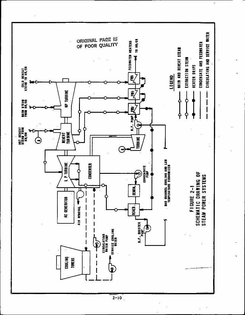
2.1.2.5 Steam Power Systems
Exhaust gas from the MHD power train contains the energy which generates thesteam in the HR/SR. This steam drives the conventional turbine generator andpowers the auxiliary turbines. The high pressure turbine uses 1,071,000 Ib/hrof steam at 1,815 psi and 1000PF and produces 45.7 MWe. Exhaust steam fromthe HP turbine is reheated to 10000? and then split, with 679,000 Ib/hr goingto the intermediate pressure turbine (10.1 MWe) and, after extractions,605,000 Ib/hr going to the low pressure turbine (44.6 MWe). This steamexhausts to the main condenser at 2 in. Hg. After allowing for losses, atotal of 128 MWe are generated by the turbine generator. The steam powercycle is shown schematically in Figure 2-1. Steam and water flow values maybe found on the heat and mass balance diagram in Appendix 2A.
Hot reheat steam is delivered to the ASU compressor turbine for a power inputof 12.3 MWe; to the two oxidant compressor turbines for an input of 23.4 MWe;and to the boiler feed pump turbines for an input of 2.6 MWe.
The steam side thermal efficiency is 39-7 percent.
2.1.2.6 Plant Auxiliary Systems
Two package boilers provide steam for plant heating and as needed for plantequipment such as the deaerators, demineralizers and flash tanks duringstartup and shutdown. Total steam output of the boilers is 200,000 Ib/hr, butstartup design requirements will ultimately determine final sizing.
The main function of the coal management facility is to transport pulverizedcoal from pressurized hoppers and inject it into the pressurized combustor.Coal handling facilities are capable of handling 2,000 tons per day with coalarriving in a unit train every five days.
The function of the Seed Management System is to receive and unload fresh seedat an average rate of 8,000 Ib/hr, to recover and recycle spent seed at therate of 16,800 Ib/hr, and to mix and pulverize both seed streams for injectioninto the pressurized MHD combustor. The remaining spent seed (11,000 Ib/hr)is trucked off-site for disposal or reprocessing.
Slag management consists of collecting, grinding, separating and transportingthe condensed mineral fraction of the coal after combustion. The slagcollected from the combustor and radiant boiler is ground and hydraulicallyremoved to dewatering facilities. Dewatered slag is trucked off-site fordisposal. The Slag Management System is designed to handle 10 tons per hourof combustor slag and 2-1/2 tons per hour of radiant boiler slag.
2-9
OF POOR QUALITY
0
O CO
C9 LU
— — COI » >-O4 CO
QCuj a ocK LLJ=3 O »CD — O— »— Q.
O I—CO CO
2-10
The electrical system delivers the electrical power generated by ETF to theutility grid; distributes power to the auxiliary systems for startup,shutdown, and normal operation; supplies emergency shutdown power when normalsource is lost; and provides an uninterruptible power supply for essentialplant equipment (such as computer, instrumentation, and controls ( I&C)) . A138 kV substation ring bus is provided to act as an interface to connect theETF topping cycle 3*4.5 kV inverter to the bottoming cycle 22 kV isolated phasebus through a unit connected step-up transformer. In addition, two stationservice step-down transformers provide JJ.16 kV power to buses for in-plantpower distribution.
2.1.2.7 Plant Services
Plant services include water management, heating, ventilating and airconditioning, cooling water, fuel oil, industrial and sanitary waste disposal,fire protection, and pneumatic systems. The design of these services followconventional practice.
2.1.3 Plant Operating Characteristics
The ETF is designed as a baseload power plant. Major prime movers haveelectric motor drives so that startup power can be supplied from off site.Heating rates of equipment during startup from a cold start condition iscontrolled by the design of the bottoming plant equipment; e.g., the allowableheating rate of the steam generator is expected to be less than the cold wallMHD channel. This assumes, however, that magnet cooldown has beenaccomplished.
Present startup concepts include an oil-fired vitiation heater to provideinitial power train heating and steam production. After gas temperaturesbetween 1,800°F and 2,200°F are achieved, pulverized coal injection into thecombustor can proceed.
The plant is designed for sustained operation down to 75 percent of ratedload. Individual subsystems may have greater turn-down; i.e., the oxidantcompressor (motor driven) is designed for controlled operation from zero to 50percent of rated load.
At rated load, gross power* is 213-0 MWe. Auxiliary power, which is theelectrical load to plant equipment to sustain plant operation, is 10.8 MWe.Net power to the plant busses for distribution is 202.2 MWe at a plantefficiency of 38 percent.
* Gross power, as used here, is the sum of the power produced in the MHD andsteam turbine generators.
2-11
PRECEDING PAGE BLANK NOT FILMED
2.2 DESIGN REQUIREMENTS AND CRITERIA
2.2.1 Operational Objectives
The system design and performance requirements for the ETF, as follows, wereestablished by the Office of MHD, U.S. Department of Energy.
The ETF shall be a commercial prototype, with a fully integrated MHDtopping/steam bottoming power plant, using coal and oxygen enriched air. Thefacility shall be a complete plant, rated at 200 MWe and capable of deliveringelectric power to a utility grid. The facility shall operate as a "baseloadplant". The facility shall also accommodate a wide range load change,including load rejection and transients.
The ETF plant shall be capable of stable operation from 75 percent to100 percent of the plant power rating, and shall be capable of reducing orincreasing the power output within this range at rates of at least 3 MW perminute.
The ETF plant efficiency (net overall) shall be a minimum of 37 percent. TheETF shall be designed and constructed in accordance with utility practice fora thirty-year life.
The primary operational objective of the ETF plant is to demonstrate thecommercial viability of power generation using an integrated MHD/steamcombined cycle power plant. This plant will have a dual role to play,however, in that it will also be used to acquire experimental data oncomponent performance under varying load conditions, interaction, andcontrollability of system components. This data can be acquired while theplant is producing power and supplying it to a utility grid.
The facility shall comply with applicable Federal, State, and localenvironmental regulations at all load levels.
2.2.2 Input Parameters
The ETF is designed to yield 200 MW net electrical power output while fired bya pulverized sub-bituminous coal from the Montana Rosebud seam. The as -received coal properties include:
H20 27$ maximum, by weightAsh 12% maximum, by weightSulfur 1.1$ maximum, by weightHHV 11,500 Btu/lb, typical dry
The design average ambient site conditions for the ETF are:
Dry bulb temperature 42°FWet bulb temperature 36°FAmbient pressure 13.0 psi
2-13
These conditions are typical of those found in eastern Montana. The summerconditions for the cooling tower design are:
Dry bulb temperature 80opWet bulb temperature 59°F
The summer wet bulb temperature will be exceeded less than 5 percent of thetime for this area.
2.2.3 Design Requirements
The ETF Design Requirements Document (DRD) was the controlling document usedin the preparation of a conceptual design. The DRD describes the purpose,general operating conditions, overall lay-out, and principal designcharacteristics of the ETF. It also defines basic plant requirements relatingto performance, durability, reliability, availability, operating range,safety, and environmental effects. The DRD also presents design conditions ofprocess flow streams for major system interface locations.
The configuration selected to achieve the operational objectives of the ETFconceptual design avoids new technology other than that essential to theoperation of the MHD power train, magnet, and HR/SR systems. Values wereestablished for a large number of interrelated design parameters and a numberof system studies were undertaken to maximize performance while minimizingcapital costs. Engineering Judgement and/or theoretical analyses were used toestablish selected parameters of the systems under development. Theseincluded combustor and channel heat losses, enthalpy extraction in thechannel, maximum temperatures in the oxidant heater, etc. (See SDD-502, "MHDPower Train and SDD-50U, "HR/SR System" for details.) The balance of thesystem design parameters were derived from the heat and mass balance describedin Section 2.3.
2-14
ORIGINAL PASS mOF POOR QUALITY
2.3 SYSTEM HEAT AND MASS FLOW BALANCE
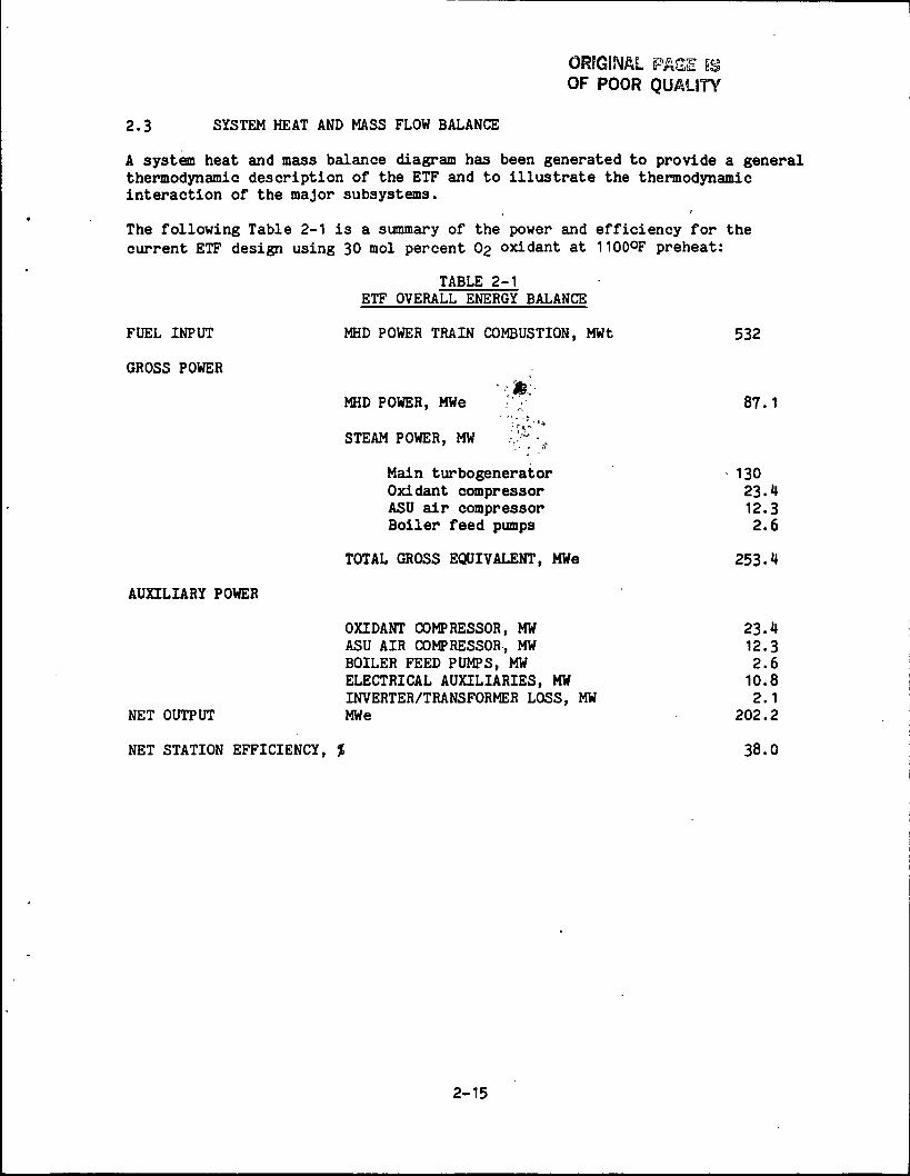
A system heat and mass balance diagram has been generated to provide a generalthermodynamic description of the ETF and to illustrate the thermodynamicinteraction of the major subsystems.
The following Table 2-1 is a summary of the power and efficiency for thecurrent ETF design using 30 mol percent 03 oxidant at 1100°F preheat:
TABLE 2-1ETF OVERALL ENERGY BALANCE
FUEL INPUT MHD POWER TRAIN COMBUSTION, MWt 532
GROSS POWER
' •' *.:•MHD POWER, MWe .' / 87.1
\ f ' ' '*
STEAM POWER, MW .v" -f
Main turbogenerator 130Oxidant compressor 23.4ASU air compressor 12.3Boiler feed pumps 2.6
TOTAL GROSS EQUIVALENT, MWe 253.4
AUXILIARY POWER
OXIDANT COMPRESSOR, MW 23.4ASU AIR COMPRESSOR, MW 12.3BOILER FEED PUMPS, MW 2.6ELECTRICAL AUXILIARIES, MW 10.8INVERTER/TRANSFORMER LOSS, MW 2.1
NET OUTPUT MWe 202.2
NET STATION EFFICIENCY, % 38.0
2-15
PRECEDING PAGE BLANK NOT FILMED
2.1* MHD PRINCIPLES AND TERMINOLOGY
2.M.1 MHD Principles
Magnetohydrodynamics (MHD) refers to the interaction of an electricallyconducting fluid with a magnetic field, and to the use of that interaction togenerate electricity. In an MHD generator, electrical energy is extracteddirectly from the kinetic and thermal energy of a fluid stream as it expandsthrough a magnetic field. It is the electromagnetic analog of a turbine. TheMHD topping cycle used in the ETF, which employs combustion gases in an opencycle, is thennodynamically equivalent to the Brayton cycle.
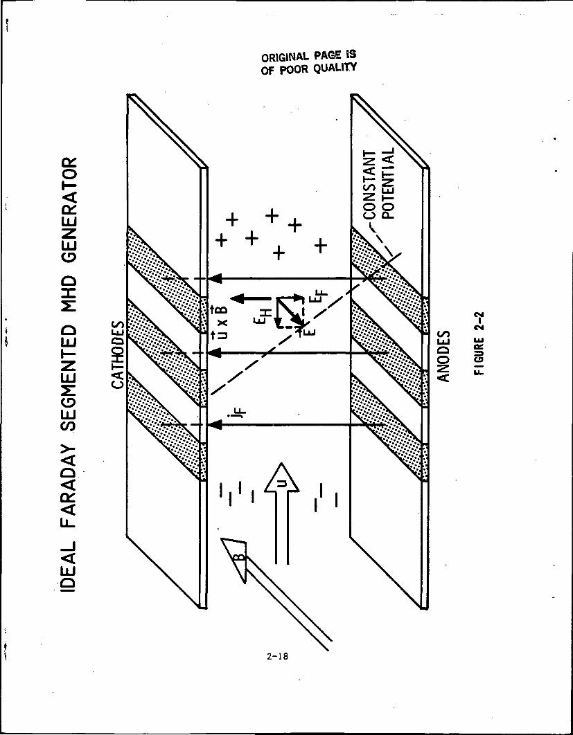
The principles of the MHD process are illustrated in Figure 2-2. Hot gasflows through the generator with velocity "U" at right angles to a strongmagnetic field "B". The potassium seed, carried in the gas, is dissociatedinto electrons and positive ions forming a dilute plasma. The electrons andions, as they move through the magnetic field, experience forces at rightangles to both their direction of motion and the magnetic field direction. Inaccordance with the right-hand rule, the positively charged ions are forcedtoward the cathode electrodes while electrons (negative charge) are forcedtowards the anode electrodes. This gives rise to a net difference inelectrical potential between the cathodes and anodes which is referred to asthe Faraday voltage. Its gradient "Ep" is known as the Faraday field and theassociated current is known as the Farraday current. The electrons, beingmuch lighter than the positive ions, tend to move sideways more quickly, whilethe ions tend to travel downstream with the gas. This gives rise to a secondpotential difference, one between the inlet and exit ends of the generator,which is referred to as the Hall voltage. This gradient, "EH", is directedupstream toward the generator inlet.
The existence of the Hall voltage requires the generator to be axiallysegmented into a large number of electrically isolated anode/cathode pairs.If the generator were built with a single pair of anodes and cathodes spanningthe length of the generator, they would short-circuit this Hall voltage. Alarge Hall current would flow through the plasma from inlet to exit and returninside the electrodes, dissipating most of the electrical energy generated bythe MHD process. The electrical power produced by the generator can bemaximized by connecting each isolated anode/cathode segment pair to anindividual load. Each anode/cathode pair becomes, in effect, an individualMHD generator, while the overall MHD generator is a composite of theseindividual units stacked end-to-end. This method of extraction, calledFaraday loading, is theoretically simple but complex to build and operate.The net potential (voltage) within the generator, a sum of the Faraday andHall voltages, generally increases both as the generator is traversed down itslength and as the generator is traversed from one side to the other. Planesof constant potential thus intersect the walls of the generator diagonally,not at right angles. Because of this, an anode at one position in thegenerator will have the same potential as a cathode nearer to the generatorinlet, and anodes and cathodes that are as the same voltage can be wiredtogether. This is called diagonal connection. It simplifies the powerextraction circuitry because the individual Faraday generators are essentiallywired in series (like battery cells) into a single load circuit, greatly
2-17
LU
LU
OLU
LU
LUCO
O<a:
LUO
ORIGINAL PAGE ISOF POOR QUALITY
* to
O
<
CM
CS
2-18
reducing the number of electrical loads which the generator electrical systemmust handle.
The Hall voltage appears in the generator as a voltage difference betweenadjacent electrodes. Insulation is provided between electrodes to preventthis voltage differential from causing leakage currents across the insulator,arcing, or even destructive breakdown. To also help reduce these occurrences,the generator is designed so that the Hall voltage gradient is always lessthan 2,500 volts/meter and the voltage difference between electrodes (theproduct of the Hall field times individual electrode width) is less than15 volts. Similar leakage problems are likely to occur on the insulating gascontainment wall between the anodes and cathodes. Therefore, the generator isdesigned to keep the Farraday field less than 4,000 volts/meter. The currentis kept below 10,000 amp/meter2 to assure long electrode lifetime.
2.4.2 MHD System Terminology
The following sections provide definitions, terms and phrases which are usedto discuss MHD generators. These definitions are specific to coal-fired,open-cycle MHD generators such as the ETF Power Train, and are not necessarilycorrect for other types of generators.
2.1.2.1 MHD Generator
The MHD Generator converts energy from a hot plasma into electrical energy.The generator includes the MHD channel, the current consolidation circuitry,and the diffuser, but not the magnet. The magnet is considered a separatesystem. Because the generation of electricity occurs in the MHD channel, theterm "generator" is frequently used synonymously with "channel".
2.4.2.2 MHD Channel '
The major component of the MHD generator is the channel. It is the ductthrough which the fast moving plasma stream is passed to yield part of itskinetic energy through the MHD process. The channel is located in a region ofhigh magnetic field and provides controlled expansion of the gas streamagainst the retarding forces of friction and the MHD interaction with themagnet field. Electrodes line the channel walls at right angles to the fielddirection to collect the currents produced by these interactions.
2.1.2.3 Plasma
Plasma is the fluid conductor used in a MHD generator and is a gaseousconductor of electricity. The plasma used in open cycle MHD is combustion gasthat is highly ionized due to its temperatures and the addition of easilyionized materials (seed).
2.4.2.4 Pressure Ratio
Pressure ratio is the ratio of inlet pressure to exit pressure of the gasstream flowing through the channel.
2-19
2.4.2.5 Enthalpy Extraction
The fraction of enthalpy extracted, usually expressed in percent, of theelectric power produced by a MHD generator, vs. the thermal power flowingthrough it.
2.4.2.6 Channel Lofting
Channel lofting refers to the aerodynamic shape of the channel and ducts whichexpand and slow the gas stream, it is the variation of transverse dimensionsof the duct with axial (i.e., the direction of flow) position.
2.4.2.7 Faraday Voltage
Faraday Voltage is the transverse voltage rise from a cathode to the opposinganode.
2.4.2.8 Hall Parameter
Hall parameter is a dimensionless number that relates axial current (along thedirection of gas flow) to electric field strength in the channel.
2.4.2.9 Hall Voltage
Hall voltage is the axial voltage rise from the channel inlet to exit. Itsoverall magnitude can be much greater than the highest Faraday voltage.
2.4.2.10 Active Length
The distance from the beginning to the end of the MHD channel's active region(where significant power generation occurs) within the magnet field, is knownas its active length. In the ETF, the active region begins at the inlet wherethe magnet field strength exceeds 4.0 teslas, and ends where it drops below3-5 teslas at the exit.
2.4.2.11 Diagonal Connection
Diagonal connection is a method of externally loading a Faraday generatorwhere individual cathodes are connected to individual anodes downstream whichhave the same voltage (due to the Hall voltage). The current zigzags severaltimes through the length of the generator before being drawn off. It isequivalent to a series connection of Faraday electrode pairs.
2.4.2.12 Diagonal MHD Generator
A diagonally connected generator is that in which the connections are made bythe diagonal bars forming the side walls of the generator.
2-20

2,4.2.13 Consolidation
Consolidation is the means used to organize the electrical energy extractedfrom the channel. The basic output from the channel is many hundreds ofseparate sources with different voltages and currents. The consolidationmeans will combine all these sources into only a few large sources, so thatconventional power conversion and transmission equipment may interface withit.
2.H.2.'U Core and Boundary Layer
Basically there are two regions of plasma flow in the channel. The core isthe region at the center of the flow (away from the channel walls), where thebulk of the MHD conversion process takes place. The flow is reasonablyuniform and temperature and conductivity are high. The boundary layer is theregion of the cold wall surface where the plasma properties are markedlydifferent and result in thermal and electrical losses.
2-21
2.5 PLANT DETAILED DESCRIPTION
This Section provides a detailed description of the ETF, including thefunctional requirements, physical definition, and interface requirements forall major subsystems, facilities, and plant services.
In addition, separate sections address conventional hazardous wastes.Environmental considerations and intrusion are described in the appropriatetechnical subsystem description.
For more detailed system design information and the related drawings for eachsystem, see the System Design Descriptions and related drawings inSection 5.5.
PRECEDING PAGE BLANK NOT FILMED
2-23
PRECEDING PAGE BLANK NOT FILMED
2.5.1 Oxidant Supply
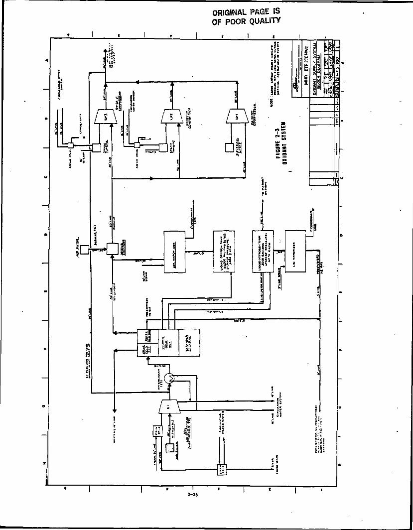
The function of the Oxidant Supply System is to provide pressurized oxidant tothe MHD Power Train at the pressure, temperature, and flow rate required foroperation. The oxidant is prepared by blending ambient air with medium purityoxygen (70 percent oxygen by volume) produced by an air separation unit. Themixture is then compressed and passed to the HR/SR for heating to a highertemperature. The system is shown schematically on Figure 2-3« For detailedsystem design information and the related drawings for the system see SDD-501in Section 5.5. Major elements of the Oxidant Supply System are:
Air Separation Unit (ASU),ASU air compressors and auxiliaries,Oxidant compressor, and auxiliaries.
System requirements include:
Parameter Remarks100* Rating 75% Rating
Oxidant delivery oxygen content 30% by volume 30% by volumeOxidant delivery pressure 73 psia 58 psiaOxidant delivery flow rate 867,852 Ib/br 650,899 Ib/br
Major interfaces are:
Steam power train,Heat recovery/seed recovery system,Circulating water system.
2.5.1.1 Air Separation Unit (ASU)
The ASU produces a medium purity (70 volume percent) oxygen stream byseparating air into its oxygen and nitrogen components in a cryogenicdistillation column (column cold box). The ASU product is delivered as a gasat near ambient conditions. Some liquid oxygen and liquid nitrogen arewithdrawn for storage for plant startup and magnet cool down.
Major elements of the ASU include:
Reversing heat exchanger (revex cold box) and reversing valves (valvecold box)Lower and upper distillation columns (column cold box)Expansion turbines and valves (expander cold box)Impurity adsorbers (adsorber/exchanger cold box)
2-25
ORIGINAL PAGE ISOF POOR QUALITY
2-26
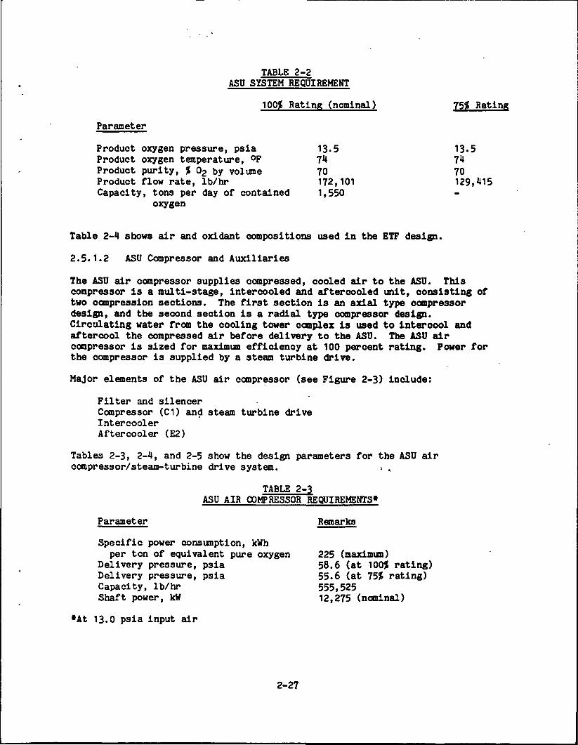
TABLE 2-2ASU SYSTEM REQUIREMENT
100$ Rating (nominal)
Parameter
Product oxygen pressure, psia 13-5Product oxygen temperature, °F 71Product purity, % 63 by volume 70Product flow rate, Ib/hr 172,101Capacity, tons per day of contained 1,550
oxygen
75* Rating
13.57170129,115
Table 2-1 shows air and oxidant compositions used in the ETF design.
2.5.1.2 ASU Compressor and Auxiliaries
The ASU air compressor supplies compressed, cooled air to the ASU. Thiscompressor is a multi-stage, intercooled and aftercooled unit, consisting oftwo compression sections. The first section is an axial type compressordesign, and the second section is a radial type compressor design.Circulating water from the cooling tower complex is used to intercool andaftercool the compressed air before delivery to the ASU. The ASU aircompressor is sized for maximum efficiency at 100 percent rating. Power forthe compressor is supplied by a steam turbine drive.
Major elements of the ASU air compressor (see Figure 2-3) include:
Filter and silencerCompressor (C1) and steam turbine driveIntercoolerAftercooler (E2)
Tables 2-3, 2-1, and 2-5 show the design parameters for the ASU aircompressor/steam-turbine drive system. : .
TABLE 2-3ASU AIR COMPRESSOR REQUIREMENTS*
Parameter
Specific power consumption, kWhper ton of equivalent pure oxygen
Delivery pressure, psiaDelivery pressure, psiaCapacity, Ib/hrShaft power, kW
•At 13.0 psia input air
Remarks
225 (maximum)58.6 (at 100$ rating)55.6 (at 75$ rating)555,52512,275 (nominal)
2-27
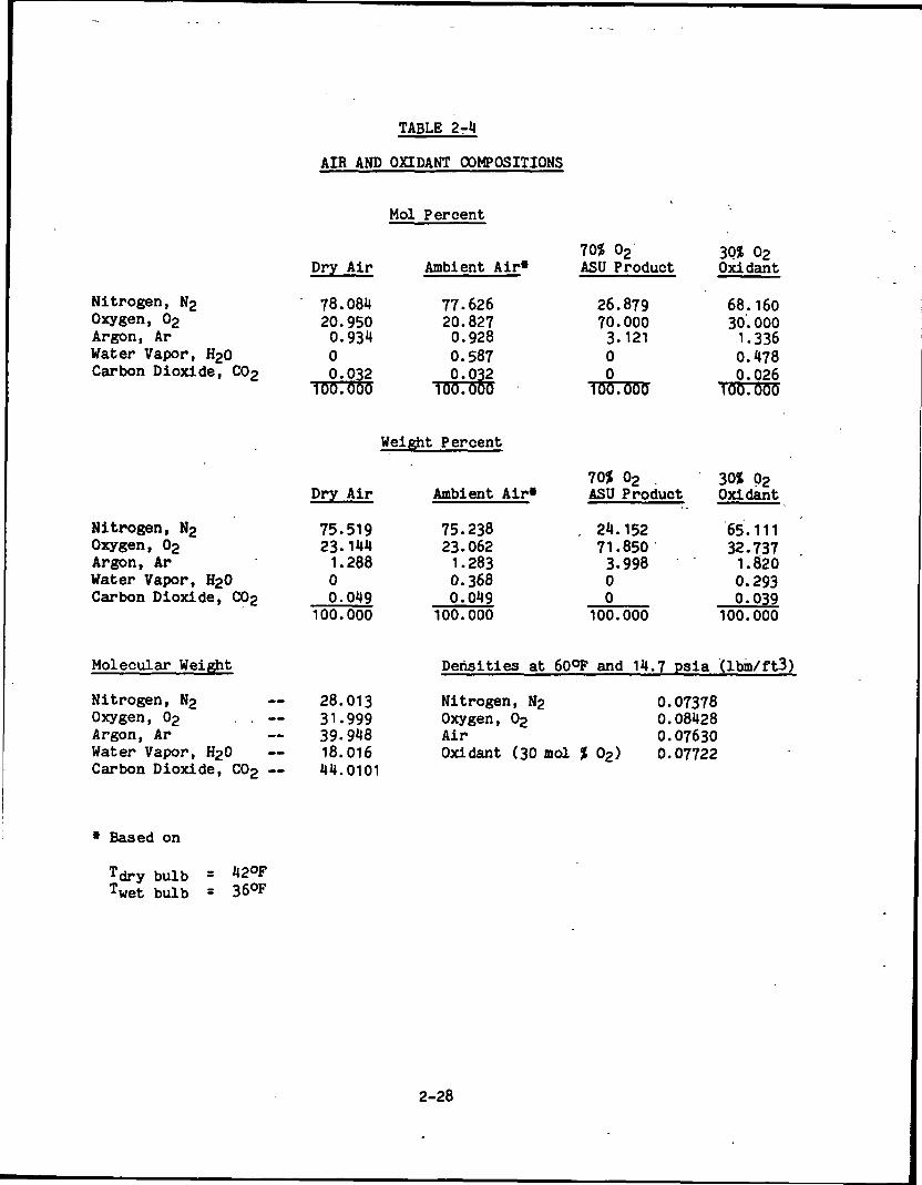
TABLE 2-4
AIR AND OHDANT COMPOSITIONS
Mol Percent
Nitrogen, N2Oxygen, 02Argon, ArWater Vapor, H20Carbon Dioxide, C02
Dry Air
78.08420.9500.93400.032
100.000
Ambient Air*
77.62620.8270.9280.5870.032
100.000
70$ 02ASU Product
26.87970.0003.12100
100.000
30$ 02Oxldant
68.16030.0001.3360.4780.026
100.000
Weight Percent
Nitrogen, N2Oxygen, 02Argon, ArWater Vapor, H20Carbon Dioxide, C02
Dry Air
75.51923.144
1.28800.049
100.000
Ambient Air*
75.23823.062
1.2830.3680.049
70$ 02ASU Product
24.15271.8503-99800
100.000 100.000
30$ 02Oxidant
65.11132.737
1.8200.2930.039
100.000
Molecular Weight
Nitrogen, N2 — 28.013Oxygen, 02 . . — 31.999Argon, Ar — 39-948Water Vapor, H20 — 18.016Carbon Dioxide, C02 — 44.0101
Densities at 6QQF and 14.7 psia (Ibm/ft3)
Nitrogen, N2Oxygen, 02AirOxidant (30 mol $ 02)
0.073780.084280.076300.07722
* Based on
Tdry bulb =Twet bulb = 36°F
2-28
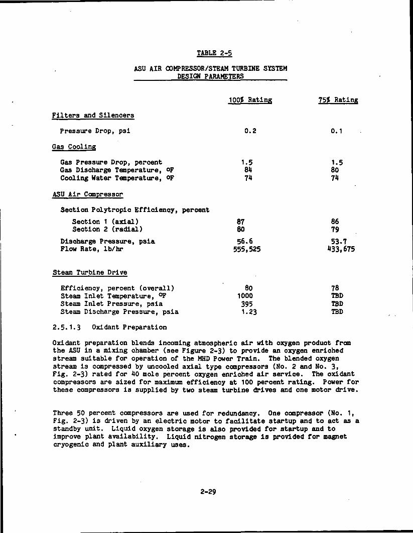
TABLE 2-5
ASU AIR COMPRESSOR/STEAM TURBINE SYSTEMDESIGN PARAMETERS
100? Rating 75? Rating
Filters and Silencers
Pressure Drop, psi 0.2 0.1
Gas Cooling
Gas Pressure Drop, percent 1.5 1.5Gas Discharge Temperature, op 84 80Cooling Water Temperature, op 74 74
ASU Air Compressor
Section Polytropic Efficiency, percent
Section 1 (axial) 87 86Section 2 (radial) 80 79
Discharge Pressure, psia 56.6 53•7Flow Rate, Ib/hr 555,525 433,675
Steam Turbine Drive
Efficiency, percent (overall) 80 78Steam Inlet Temperature, °F 1000 TBDSteam Inlet Pressure, psia 395 TBDSteam Discharge Pressure, psia 1.23 TBD
2.5.1.3 Oxi dant P reparati on
Oxidant preparation blends incoming atmospheric air with oxygen product fromthe ASU in a mixing chamber (see Figure 2-3) to provide an oxygen enrichedstream suitable for operation of the MHD Power Train. The blended oxygenstream is compressed by uncooled axial type compressors (No. 2 and No. 3,Fig. 2-3) rated for 40 mole percent oxygen enriched air service. The oxidantcompressors are sized for maximum efficiency at 100 percent rating. Power forthese compressors is supplied by two steam turbine drives and one motor drive.
Three 50 percent compressors are used for redundancy. One compressor (No. 1,Fig. 2-3) is driven by an electric motor to facilitate startup and to act as astandby unit. Liquid oxygen storage is also provided for startup and toimprove plant availability. Liquid nitrogen storage is provided for magnetcryogenic and plant auxiliary uses.
2-29
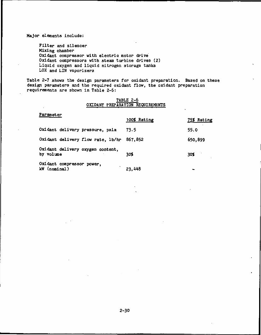
Major elements include:
Filter and silencerMixing chamberOxidant compressor with electric motor driveOxidant compressors with steam turbine drives (2)Liquid oxygen and liquid nitrogen storage tanksLOX and LIN vaporizers
Table 2-7 shows the design parameters for oxidant preparation. Based on thesedesign parameters and the required oxidant flow, the oxidant preparationrequirements are shown in Table 2-6:
TABLE 2-6OXIDANT PREPARATION REQUIREMENTS
Parameter100* Rating 751 Rating
Oxidant delivery pressure, psia 73-5 55.0
Oxidant delivery flow rate, Ib/hr 867,852 650,899
Oxidant delivery oxygen content,by volume 30$ 30J
Oxidant compressor power,kW (nominal) " 23,448
2-30
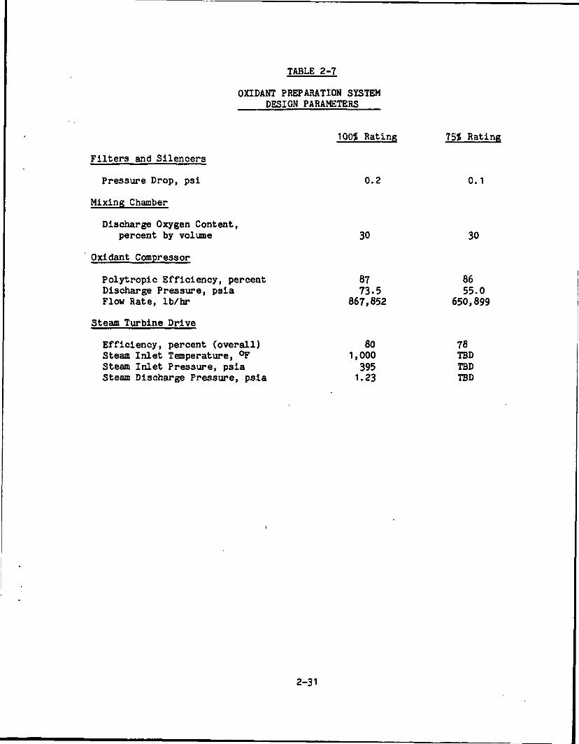
TABLE 2-7
OHDANT PREPARATION SYSTEMDESIGN PARAMETERS
100$ Rating 75$ Rating
Filters and Silencers
Pressure Drop, psi 0.2 0.1
Mixing Chamber
Discharge Oxygen Content,percent by volume 30 30
Oxidant Compressor
Polytropic Efficiency, percent 87 86Discharge Pressure, psia 73-5 55.0Flow Rate, Ib/hr 867,852 650,899
Steam Turbine Drive
Efficiency, percent (overall) 80 78Steam Inlet Temperature, °F 1,000 TBDSteam Inlet Pressure, psia 395 TBDSteam Discharge Pressure, psia 1.23 TBD
2-31
PRECEDING PAGE BLANK NOT FILMED
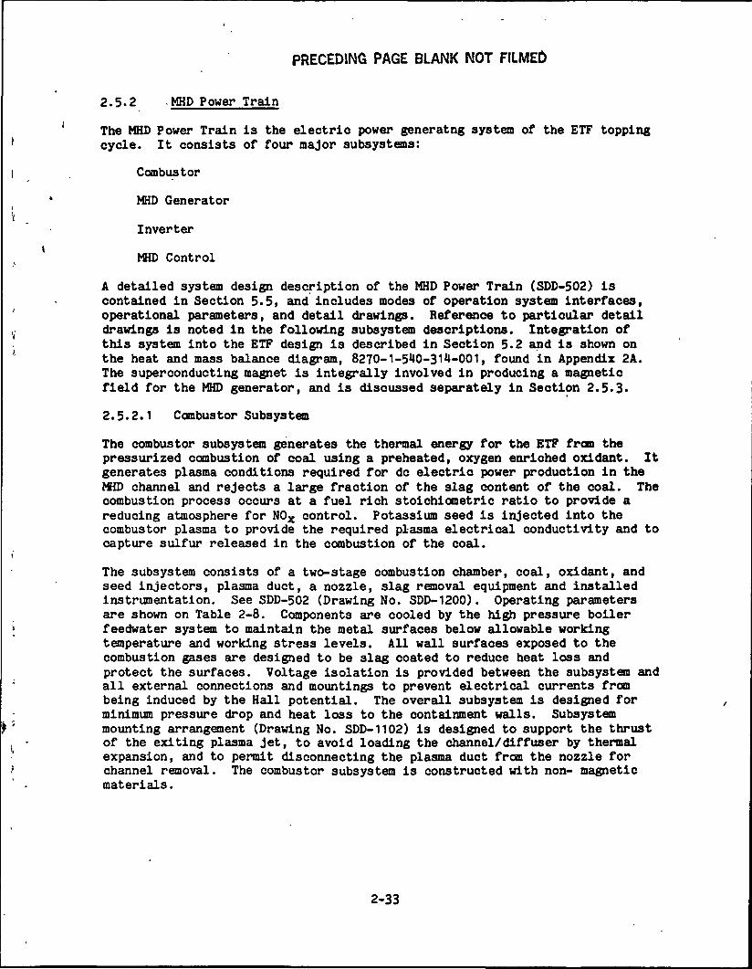
2.5.2 .MHD Power Train
The MHD Power Train is the electric power generatng system of the ETF toppingcycle. It consists of four major subsystems:
Combustor
MHD Generator
Inverter
MHD Control
A detailed system design description of the MHD Power Train (SDD-502) iscontained in Section 5.5, and includes modes of operation system interfaces,operational parameters, and detail drawings. Reference to particular detaildrawings is noted in the following subsystem descriptions. Integration ofthis system into the ETF design is described in Section 5.2 and is shown onthe heat and mass balance diagram, 8270-1 -5**0-31 -001, found in Appendix 2A.The superconducting magnet is integrally involved in producing a magneticfield for the MHD generator, and is discussed separately in Section 2.5.3*
2.5.2.1 Combustor Subsystem
The combustor subsystem generates the thermal energy for the ETF from thepressurized combustion of coal using a preheated, oxygen enriched oxidant. Itgenerates plasma conditions required for dc electric power production in theMHD channel and rejects a large fraction of the slag content of the coal. Thecombustion process occurs at a fuel rich stoichiometric ratio to provide areducing atmosphere for NOX control. Potassium seed is injected into thecombustor plasma to provide the required plasma electrical conductivity and tocapture sulfur released in the combustion of the coal.
The subsystem consists of a two-stage combustion chamber, coal, oxidant, andseed injectors, plasma duct, a nozzle, slag removal equipment and installedinstrumentation. See SDD-502 (Drawing No. SDD-1200). Operating parametersare shown on Table 2-8. Components are cooled by the high pressure boilerfeedwater system to maintain the metal surfaces below allowable workingtemperature and working stress levels. All wall surfaces exposed to thecombustion gases are designed to be slag coated to reduce heat loss andprotect the surfaces. Voltage isolation is provided between the subsystem andall external connections and mountings to prevent electrical currents frombeing induced by the Hall potential. The overall subsystem is designed forminimum pressure drop and heat loss to the containment walls. Subsystemmounting arrangement (Drawing No. SDD-1102) is designed to support the thrustof the exiting plasma jet, to avoid loading the channel/diffuser by thermalexpansion, and to permit disconnecting the plasma duct from the nozzle forchannel removal. The combustor subsystem is constructed with non- magneticmaterials.
2-33
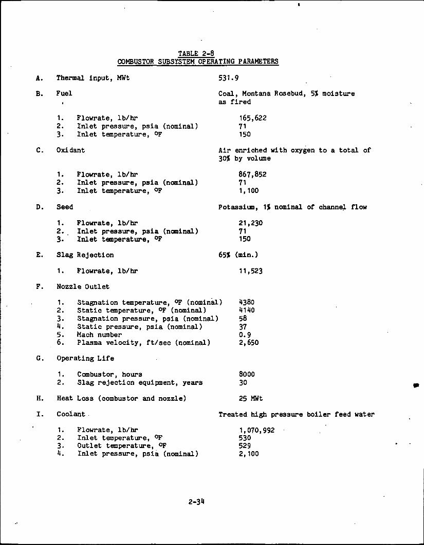
TABLE 2-8COMBUSTOR SUBSYSTEM OPERATING PARAMETERS
A.
B.
H.
I.
Thermal input, MWt
Fuel
1. Plowrate, Ib/hr2. Inlet pressure, psia (nominal)3. Inlet temperature, °F
Oxidant
1.2.3-
Seed
Plowrate, Ib/hrInlet pressure, psia (nominal)Inlet temperature, °F
1. Plowrate, Ib/hr2. Inlet pressure, psia (nominal)3* Inlet temperature, °F
Slag Rejection
1. Plowrate, Ib/hr
Nozzle Outlet
531-9
Coal, Montana Rosebud, 5% moistureas fired
165,62271150
Air enriched with oxygen to a total of30$ by volume
867,852711,100
Potassium, 1$ nominal of channel flow
21,23071150
65* (min.)
11,523
1. Stagnation temperature, °F (nominal) 13802. Static temperature, °F (nominal) 41403. Stagnation pressure, psia (nominal) 584. Static pressure, psia (nominal) 375. Mach number 0.96. Plasma velocity, ft/sec (nominal) 2,650
Operating Life
1. Combustor, hours2. Slag rejection equipment, years
Heat Loss (combustor and nozzle)
Coolant
1. Flowrate, Ib/hr2. Inlet temperature, °F3- Outlet temperature, °FH. Inlet pressure, psia (nominal)
800030
25 MWt
Treated high pressure boiler feed water
1,070,9925305292,100
2-34
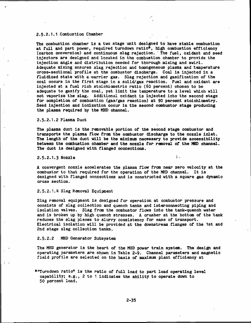
2.5.2.1.1 Combustion Chamber
The combustion chamber is a two stage unit designed to have stable combustionat full and part power, required turndown ratio*, high combustion efficiency(carbon conversion) and continuous slag rejection. ' The fuel, oxidant and seedinjectors are designed and located in the combustion chamber to provide theinjection angle and distribution needed for thorough mixing and swirl.Adequate mixing ensures slag rejection and homogeneous plasma and temperaturecross-sectional profile at the combustor discharge. Coal is injected in afluidized state with a -carrier gas. Slag rejection and gasification of thecoal occurs in the first stage in a solid/gas reaction. Fuel and oxidant areinjected at a fuel rich stoichiometric ratio (60 percent) chosen to beadequate to gasify the coal, yet limit the temperature to a level which willnot vaporize the slag. Additional oxidant is injected into the second stagefor completion of combustion (gas/gas reaction) at 90 percent stoichiometry.Seed injection and ionization occur in the second combustor stage producingthe plasma required by the MHD channel.
2.5.2.1.2 Plasma Duct
The plasma duct is the removable portion of the second stage combustor andtransports the plasma flow from the combustor discharge to the nozzle inlet.The length of the duct will be the minimum necessary to provide accessibilitybetween the combustion chamber and the nozzle for removal of the MUD channel.The duct is designed with flanged connections.
2.5.2.1.3 Nozzle i •
A convergent nozzle accelerates the plasma flow from near zero velocity at thecombustor to that required for the operation of the MHD channel. It isdesigned with flanged connections and is constructed with a square gas dynamiccross section.
2.5.2.1.4 Slag Removal Equipment
Slag removal equipment is designed for operation at combustor pressure andconsists of slag collection and quench tanks and interconnecting piping andisolation valves. Slag from the combustor flows into the tank-quench waterand is broken up by high quench stresses. A crusher at the bottom of the 'tankreduces the slag pieces to slurry consistency for ease of transport.Electrical isolation will be provided at the downstream flanges of the 1st and2nd stage slag collection tanks.
2.5.2.2 MHD Generator Subsystem
The MHD generator is the heart of the MHD power train system. The design andoperating parameters are shown in Table 2-9. Channel parameters and magneticfield profile are selected on the basis of maximum plant efficiency at
*"Turndown ratio" is the ratio of full load to part load operating levelcapability; e.g., 2 to 1 indicates the ability to operate down to50 percent load.
2-35
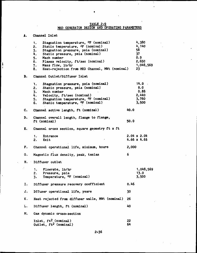
TABLE 2-9MHD GENERATOR DESIGN AND OPERATING PARAMETERS
A. Channel Inlet
1. Stagnation temperature, °F (nominal) 1,3802. Static temperature, °F (nominal) 4,1*103. Stagnation pressure, psia (nominal) 584. Static pressure, psia (nominal) 375. Mach number 0.96. Plasma velocity, ft/sec (nominal) 2,6507. Mass flow, Ib/hr 1,018,5698. Heat-rejection from MHD Channel, MWt (nominal) 23
B. Channel Outlet/Diffuser Inlet
1. Stagnation pressure, psia (nominal) 14.02. Static pressure, psia (nominal) 9.03. Mach number • 0.884. Velocity, ft/sec (nominal) 2,4405. Stagnation temperature, °F (nominal) 3,7606. Static temperature, °F (nominal) 3,500
C. Channel active length, ft (nominal) 40.0
D. Channel overall length, flange to flange,ft (nominal) 50.0
E. Channel cross section, square geometry ft x ft
1. Entrance 2.04 x 2.042. Exit 4.66 x 4.66
F. Channel operational life, minimum, hours 2,000
G. Magnetic flux density, peak, teslas 6
H. Diffuser outlet
1. Flowrate, Ib/hr 1,048,5692. Pressure, psia 13.03. Temperature, °F (nominal) 3,500
I. Diffuser pressure recovery coefficient 0.46
J. Offuser operational life, years 30
K. Heat rejected from diffuser walls, MWt (nominal) 26
L. Diffuser length, ft (nominal) 40
M. Gas dynamic cross-section
Inlet, ft2 (nominal) 22Outlet, ft2 (nominal) 64
2-36
conditions minimizing compressor power, channel heat loss, and oxygenenrichment requirements. These criteria result in a magnetic field having a6 teala* peak and a channel active length of 12.1 meters from U teslas at theinlet and to 3.5 teslas at the exit end. The overall channel length is16 meters. Channel inlet and outlet flanges are located in a magnetic fieldof less than 0.5 teslas to minimize the destructive effect of circulatingcurrents. *
iThe MHD generator subsystem (Drawings SDD-1101 and SDD-1102) consists of theMHD channel, consolidation circuitry, and a diffuser. Plasma flows from thenozzle through the MHD channel producing dc electric power by the interactionof plasma with the magnetic field. Hot exhaust gas from the channel flows tothe diffuser which reduces velocity and provides pressure recovery. Thediffuser is designed to tailor the outlet pressure and velocity to the HR/SRinlet requirements. The dc electric power produced in the channel isconsolidated and organized by the consolidation circuitry and is provided tothe inverter subsystem for conversion to ac power.
The MHD channel with support structure is mounted in the warm bore of the 6tesla superconducting magnet (Drawings SDD-1300 and SDD-1301). Periodicremoval and replacement of the channel is anticipated. This requiresprovisions for disconnecting the channel from the combustor and diffuser, andfor pull space and handling equipment.
2.5.2.2.1 MHD Channel
The channel is designed to the specified 6-tesla peak-magnetic field profile.Its active section (12.1 meters) incorporates 701 electrode pairs and isdefined as that portion of the channel lying between the field values of4 teslas at the entrance and 3.5 teslas at the exit. Within the activesection, the channel will be of the diagonally connected Faraday type whichincorporates segmented electrode walls and bar type insulator wall elements.
These electrodes and wall elements are copper, water cooled, and areelectrically insulated from each other. Anode electrodes are capped withplatinum. Electric power will also be extracted from the inlet and outletsections lying between the active section and the flanges. These sectionswill be of the diagonal window frame type and be fabricated of copper withprovisions for water cooling.
The channel will be cooled with high purity water from the boiler feedwatersystem. Each electrode and wall element incorporates a nickel plated coolantpassage and inlet and outlet coolant connections. A water manifoldingarrangement is provided for inlet and discharge coolant water from eachelectrode and wall element. Flexible hose is Installed between the channelwater coolant connections and the water manifolds for electrical isolation.
* One tesla is a magnetic induction or magnetic flux density equivalent to1 x 101* gauss.
2-37

The channel electrodes and Insulators are assembled within a pressure vesselfabricated from G-11 glass/epoxy composite which also provides box beamstructural support. An external structure (Drawing SDD-1301) supports thechannel, coolant water manifolding and the power take-off electric cables inthe magnet warm bore. This assembly is designed for rapid installation andremoval of the channel. A separate electric power take-off cable is connectedto each electrode terminal. Due to the large number of electrodes, the cableswill be bundled to minimize space packaging requirement. Approximately30 percent of the- power take-off cables will be led out at channel inlet andthe remainder at the channel outlet. Electric connectors will be used forconnecting the power take-off cables to the consolidation circuitry.
2.5.2.2.2 Consolidation Circuitry
The electric consolidation circuitry matches the raw electric power outputfrom the MHD channel to the input requirements of the inverters. Electricpower from groups of electrodes taken at many different source voltages andcurrents are combined and converted into a few stable direct current sources.The consolidation circuitry acts to control the channel loading, regulateelectrode currents within established limits and stabilize the MHD channeloperation. The consolidation circuitry is designed to provide Faraday loadingof the channel electrodes while diagonally connecting them to take advantageof the Hall potential and thus provide power at the highest possible voltage(see Ddrawings SDD-1501, SDD-1502, SDD-1503, and SDD-1501).
2.5.2.2.3 Diffuser
The diffuser is installed between the channel outlet and HR/SR inlet. Thefunction of the diffuser is to decelerate the nearly sonic hot exhaust gasesfrom the channel before exhausting into the HR/SR at essentially ambientpressure. The diffuser is designed for operation with slag coated walls andis constructed of non-magnetic materials. Diffuser size and divergence angleare selected for maximum pressure recovery factor. The diffuser designincorporates two removable sections required for channel removal. Thediffuser cooling is designed for steam generation and the cooling circuits areintegrated with the HR/SR boiler (drawings SDD-1HOO, SDD-U01, and SDD-1402).
2.5.2.3 Inverter Subsystem
Power from the channel is extracted using one end-to-end connection, and fiveadditional extraction points for a total of 89 MWe. A line-commutated systemusing both 20 MW and 4 MW inverters will invert the dc power taken from theelectrodes to ac power for delivery to the 3H.5 kV ac bus. Specific filterswill reduce the 5th, 7th, 11th, and 13th harmonics and a combined filtersystem will be used for all higher harmonics. Each inverter has bypassprotection in the event of failure and dc breakers are installed in the eventan entire line of inverters fail. The inverter building is forced air cooledto reduce volume and improve reliability. Details of this subsystem areprovided in SDD-505, in Section 5.5.
2-38
2.5.2.4 MHD Control Subsystem
The MHD control subsystem controls those energy conversion processes withinthe MHD channel which are directly involved with regulating two-terminal dcpower and producing the plasma flow rates required by power demand. Thissubsystem controls and regulates combustor operation and plasma conductivityby controlling coal, oxidant and seed input to the combustor for the requiredpower level demand. The subsystem controls the MHD channel electrical loadthrough sensing and measurement of the electrode power take-off currents andvoltages, and the switching and modulation of active electrical controlelements within the consolidation network. It also acts to regulate the flowof two terminal dc electrical power into the inverter and to connect ordisconnect itself from the inverter as required (Drawing SDD-1500).
This subsystem informs the supervisory control system (facility controlsystem) of the status of the MHD power train and detects abnormal operation.It stabilizes operation of the power train within its operational rangethrough coordinated control of the combustor, generator, and electricalconsolidation circuitry. The subsystem is designed to protect the MHD powertrain system. In the event of abnormal operation, the control subsystem willinitiate corrective action within the required response time.
2-39
PRECEDING PAGE BLANK NOT FILMED
2.5.3
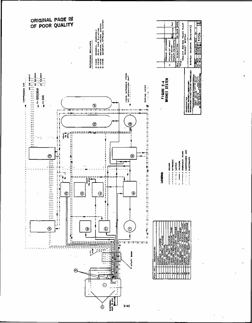
The Magnet System involves the use of advanced superconducting magnet '"technology to provide the magnetic field required by the MHD channel for powergeneration. The system consists of the magnet and accessory equipment ascontained in the following subsystems and shown on Figure 2-4:
Magnet assemblyCryogenic support equipmentPower supply and dump equipmentProtection/control circuitVacuum pumping equipmentRoll aside drive equipment
The magnet assembly consists of liquid-helium-cooled superconducting coilsprotected by a thermally insulated enclosure with the warm bore extendinghorizontally through the center. The outline dimensions of the magnetassembly and the dimensions of the cavity are shown on drawing D4441 ofSDD-503, Section 5.5.
The cryogenic support equipment consists of a helium refrigerator/liquifier/compressor assembly, storage tanks, heat exchangers, transfer lines, andcontrols required for magnet cool-down and maintaining the low temperaturesrequired by the magnet coils. This equipment will maintain these lowtemperatures for extended periods of time.
The power supply and dump equipment consists of a rectifier-type dc powersupply, dump resistors, circuit-breaker and controls. This equipment isrequired for charging the magnet, maintaining it at the desired fieldstrength, and discharging it under both normal and emergency shutdownconditions.
Protection and control equipment consists of instrumentation to detectabnormal conditions in the magnet's superconducting coils and controls toautomatically activate protective measures. Also included are instruments andcontrols to permit remote monitoring and manual control of major functions ofthe magnet and associated equipment at the main control room.
Vacuum pumping equipment consists of diffusion and mechanical pumps forevacuating the magnet vacuum jacket during initial magnet cooldown. Thissystem will also remove from the jacket any helium leakage that may occur fromthe coil container during magnet operation.
The roll aside drive equipment consists of hydraulic cylinders for moving themagnet on its tracks and the associated hydraulic pump package.
The magnetic field produced in the region surrounding the magnet is a hazardto personnel and equipment. This hazard exists only when the magnet ischarged. A fringe magnetic field extends outward from the charged magnet asfar as 270 feet, at which distance the magnetic induction level will be0.0005 tesla (5 gauss). Within a perimeter formed by a varying distance of82 feet by 100 feet from the magnet (0.01 tesla), sensitive equipment is
2-41
ORIGINAL PAGE ISOF POOR QUALITY J!
Hi!|!M
\l52
Mo2*
!g
t\*in
IMSi?
miliiif
S 5 5 i
I . I
*!si<i
W r
!»
i»
ORIGINAL PAGE SSOF POOR QUALITY
excluded and the length of time that approved personnel are allowed to remainin the area is also limited. This exclusion limit is an interim design valueand is subject to future change.
The superconducting windings must be at liquid helium temperature foroperation. Initially, the windings must be cooled from room temperature toliquid helium temperature, a process requiring up to 30 days. After coolingto design temperature, the magnet can be charged and discharged relatively,quickly. It is planned that the magnet will be kept cold continuously forlong periods of time, being allowed to warm up only in the event of a facilityshutdown of several months duration or some other unusual circumstance.
Emergency shutdown of the magnet is accomplished by the activation of circuitbreakers in the dc power supply system, causing all magnet current to flowthrough a water-cooled resistor package. The emergency discharge time fromfull field to 0.04 full field (current 1000 A) is less than 1 minute.Discharge to 0 field is less than 3 minutes.
Both manual and automatic activation of the circuit breaker are provided.Manual operation will be by means of an emergency push-button at the maincontrol station of the facility. Automatic operation will be actuated by aquench protection system and/or other sensors as described in Section 5.5.
2.5.3.1 Magnet Assembly
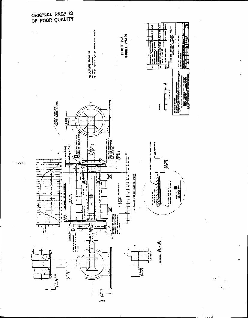
The magnet windings consist of a pair of saddle-shaped coils, each made of 572turns of superconducting, cable-type conductor. The turns are insulated fromeach other and are individually supported by a substructure consisting ofstacks of fiber glass-plastic plates notched to receive the conductors. Thewindings are designed to produce the peak on-axis field of 6 teslas and thefield profile along the axis as required for channel performance, with uniformfield throughout cross-sections. The design current density in the conductoris constant throughout and is conservatively low (1.42 x 10' A/m ). The fieldprofile and bore dimensions are shown on Figure 2-5.
The winding of each coil is made up of 26 saddle-shaped layers, each layercontaining 22 turns. Through-bolts are used to clamp the winding andsubstructure in place in the coil containers. After the windings areinstalled, a cover plate is welded in place. A spring plate between cover andwinding and spring-shims at the inner wall of the coil container, are providedto compress the winding within the coil container, thereby minimizingconductor motion during charging.
Each coil, with its substructure is enclosed in a heavy-walled, stainlesssteel containment vessel and immersed in liquid helium. The substructureincorporates a system of passages which ensure access for helium coolant toall parts of the windings. This substructure is also designed to supportindividual conductors against both gravity and magnetic forces and to transmitthe total accumulated forces to the walls of the containment vessel. Theseforces are then transmitted through these walls to the main force containmentstructure which is external to the containment vessel.
2-43
ORIGINALOF POOR QUALITY
I3
«l »I; :•
an
x
*i
2-44

ORIGINAL PAGE «OF POOR QUALITY
The superconducting cable consists of wires made of two materials, namely,multi-filament NbTi/Cu monolithic wire and OFHC copper wire. The criticalcurrent for the cable is 28,700 A at -451.5°F with a ratio of operating tocritical current of 0.85. The cable conductor has been designed to be stablerelative to the disturbances expected during operation. This implies thatconductor sections which are driven out of the superconducting state and intoa normal condition are sufficiently well cooled to allow recovery to asuperconducting condition.
The total weight of the magnet is 2,000,000 Ib with a length of 54.4 feet. Aunique design feature of the ETF magnet is its ability to roll 34 feet to anopen area for removal and replacement of the channel. Fringe fields from themagnet may have adverse effects on personnel and equipment and as a result,restrictions have been applied to the placement of auxiliary equipment and theaccess of personnel.
2.5.3.2 Cryogenic Support Equipment
The supporting cryogenic equipment for the superconducting magnet includes:
Helium refrigerator/liquifier
Helium compressor package
Liquid helium storage dewar
Gaseous helium storage tanks
Liquid nitrogen storage dewar
Cool-down heat exchanger
Warm-up heat exchanger
The helium refrigerator/liquifier incorporates a precooled expansion enginecycle using normal boiling liquid nitrogen as the precoolant. Based on arated capacity of 33 gallons per hour helium liquifaction (gas returned at80°F) and 250 watts refrigeration (gas returned at approximately -451.5°F) theinput power requirement for the refrigerator/liquifier system will beapproximately 500 kW. Equipment includes screw-type compressors, turbine-typeexpansion engines and a large storage dewar to store the liquid heliumproduced. Liquid helium is transferred to the magnet as required to maintainthe operating level of liquid in the magnet winding containment dewar.Transfer is accomplished by pressurization of the storage dewar and iscontrolled automatically by a valve in the transfer line.
A portion of the helium boil-off from the magnet dewar is utilized to cool thevapor-cooled power leads. This portion is raised to room temperature inpassing through the leads and is then returned to the helium compressorsuction. The balance of the helium boil-off is returned at near liquid heliumtemperature, via vacuum insulated piping, to the refrigerator/liquifier.
. 2-45
The liquid nitrogen system, consisting of a liquid nitrogen storage dewar,pressurizing coils, piping and controls, is provided for three purposes:(1) to provide cooling for the thermal shield in the magnet dewar, (2) toprovide coolant for the closed-loop gaseous helium circuit (including cool-down heat exchanger) used for initial cool-down of the magnet, and (3) toprovide preceding for the helium refrigerator/liquifier.
During operation of the power plant, make-up liquid nitrogen is supplied tothe liquid nitrogen storage tank from the Air Separation Unit (ASU) whichprovides oxygen enrichment for the topping cycle. When the plant and ASU arenot in operation, make-up liquid nitrogen is supplied by bulk transport fromcommercial suppliers, directly to the storage dewar.
The liquid nitrogen storage dewar is pressurized to permit transfer of liquidto the magnet thermal shield, refrigerator/liquifier, and cool-down heatexchanger. Nitrogen gas vented from these items of equipment is vented toatmosphere via a collection system. The estimated liquid nitrogen consumptionof the magnet system under normal operating conditions is 56 gallons per hour.
2.5.3-3 Power Supply and Dump Equipment
Power supplied to the magnet will be direct current that is obtained from theplant's medium voltage ac system via a step down transformer. The transformersecondary windings will feed solid state diode and silicon controlledrectifier bridges necessary to produce dc at the required current and voltagelevels.
The power supply system incorporates controls to permit energizing the magnetat preselected constant voltage and to permit operation in a constant currentmode upon reaching the desired operating magnetic field. Normal discharge ofthe magnet is through the power supply. Emergency (fast) discharge of themagnet is accomplished by using a system of'dc switches to disconnect the .rectifier from the magnet, thereby causing the magnet to discharge throughwater-cooled resistors. The design covers a fault or disturbance thatinitiates a quench (reversion to resistive state) in the superconductingwindings; i.e., the emergency discharge system is capable of discharging themagnet fast enough to prevent damage by overheating.
2.5.3-1* Protection/Control Circuit
The protection/control circuitry protects against adverse effects of magnetsystem malfunction and permits remote monitoring and control of majorfunctions of the magnet and associated equipment at the station control room.
The major elements of protection/control circuitry are:
1. Magnet quench detection system
2. Magnet liquid helium level monitoring system
2-U6
3. Vacuum monitoring system
4. Vapor-cooled power lead temperature monitoring system
5. Automatic warning/emergency shutdown system responsive to criticalmonitored parameters
6. Remote magnet charge/discharge controls
Requirements include:
1. The quench detection/automatic shutdown system shall initiate emergencydischarge at a short enough interval after appearance of local windingquench to ensure that no part of the winding is damaged by overheating.
2. The lead temperature monitoring system shall initiate emergency shutdownin tine to prevent damage to leads by overheating, under conditionsincluding loss of coolant to leads.
2.5.3*5 Vacuum Pumping Equipment
The vacuum system for the magnet dewar and cryogenic plant will include acombination mechanical roughing pump and oil diffusion pump to establish avacuum in the low 1(H* torr range. System cryopumping will then reduce thevacuum to the operating level>which will be 10-5 torr.
2-47
PRECEDING PAGE BLANK NOT FILMED
2.5.1 Heat Recovery/Seed Recovery (HR/SR)
The HR/SR includes the radiant boiler, superheaters, reheaters, oxidantheater, high temperature economizer, and electrostatic precipitator. Itsmulti-functions include:
Generating and superheating steam
Seed recovery
Preheating the oxidant
Capturing particulates
Heating feedwater
Providing flue gas residence time at high temperatures for chemicalreactions to proceed to the required degree of equilibrium.
Baseload operating points for the HR/SR subsystems are shown on the SystemHeat and Mass Balance Diagram 8270-1-510-314-001. Figure 2-6 is a schematicillustration of the HR/SR.
2.5.1.1 Boiler
Boiling of the feedwater takes place in the vertical water-tube walls in thefirst section of the radiant boiler chambers. The initial chamber also servesas a NOx control furnace. This is done by lining the tube walls with arefractory to lessen the rate of temperature change of the gas and alsoprovide a time delay until the gas reaches the 'freeze1 temperature for NOx ofabout 2,900°F. Since there exists a reducing atmosphere in this region, therefractory also serves as a corrosion barrier between the gas and the waterwalls. The mixture of steam and water rises to the steam drum from whichwater is recirculated and steam continues to the superheater.
Downstream of the NOx control furnace (see Subsection 2.5.6.2.2) a secondsection of the radiant boiler has bare metal tube walls. The reducedcombustion rate combined with the high heat transfer to the bare wallsprevents high temperature which could increase NOx generation. The boilerassembly system includes the slag, ash and spent seed collector at the bottomof the boiler chambers. This collector consists of hoppers which collect theslag and direct it into quenchers which freeze and break it into smallfragments. These fragments are discharged to the seed and slag managementsystems (Sections 2.5.6.4 and 2.5.6.5).
2.5.4.2 Superheater
Steam formed in the boiler walls is separated from the two-phase mixture inthe drum and is superheated in the convective passes and radiant panels of thesuperheater. Steam leaving the superheater at 1,005°F and 1,910 psia is pipedto the main steam turbine.
2-49
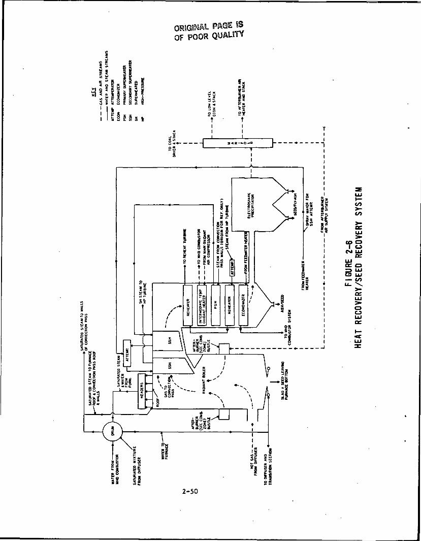
PAGE S3OF POOR QUALITY
i
1 '
B
-/ * J 1 1-§?3^LJ ^ 1
Sw
si 5
CO
CO
CM UJae
UJor oS UJ
UJ— to
oo
2-50
A spray attemperation unit is available to prevent overheating of final steam.Water for attemperation is piped from the feedwater system to the inlet of thefinal stage of superheat.
2.5.4.3 Reheater
Steam discharged from the high pressure turbine, except for that extracted orlost through leakage, is piped back to the reheater where its temperature israised to 1000°F. Spray attemperation is provided for the reheat steamentering the second stage reheater to control reheater outlet steamtemperature.
2.5.4.4 Oxidant Heater
The oxidant heater is a gas-to-gas heat exchanger containing a convectiveheater section and a radiant heater section. The oxidant, 30 mol percentoxygen, enters the heater at 430°F and exits at 1,100op to the combustor.
2.5.4.5 High Temperature Economizer
The high temperature economizer is a gas-to-water heat exchanger located inthe final pass of the steam generation system. Feedwater is heated by theflue gas. Flue gas temperature at exit is maintained at the 480°F levelsince, after participate removal by an ESP (Section 2.5.4.6), over 40 percentof the flue gas is recycled to the pulverizers for drying and transport of thecoal fines.
2.5.4.6 Electrostatic Precipitator (ESP)
The ESP is designed to operate near the 500°F level and the collector area issized to handle finer particulates than occur in conventional power plants.
2-51
PRECEDING PAGE BLANK NOT FILMED
2.5.5 Steam Power Systems
The MHD-ETF design utilizes topping cycle heat recovery equipment (HR/SR) totransfer the MHD Power Train exhaust gas waste heat into steam generation.The generated steam is used in a conventional Rankine turbine generator"bottoming" cycle to produce additional electric power. Part of the steam isused for turbine drives to power auxiliary equipment. The chosen cyclefeatures reheat of the steam (in the HR/SR), regenerative feedwater heating, acondensing low pressure turbine, and cooling towers as a heat sink. Aschematic diagram of the cycle is shown on Figure 2-1, followingSection 2.1.2.5. Steam and water flow conditions may be found on the heat andmass balance diagram, 8270-1-540-31^-001 in Appendix 2A.
Main steam generated in the HR/SR passes through a high pressure turbine andreturns to the HR/SR for reheating. The steam then flows through a reheat, orintermediate pressure, turbine, and then through a low pressure turbine whichexhausts into a water cooled condenser. The condensed steam, or condensate,is pumped through demineralizers, a deaerator, and then through regenerativefeedwater heaters before returning to the MHD cycle as a coolant. The waterultimately returns to the boiler drum of the HR/SR to complete the cycle.
2.5.5.1 Main and Reheat Steam
The main steam system conveys steam at design conditions, 1,815 psia and1000°F, to the high pressure turbine. Reheat steam is conveyed from the highpressure turbine exhaust, through the reheater where its temperature is raisedto 1000°P, and then to the intermediate pressure turbine. Reheat steam isalso supplied to the steam turbine drives for the ASU compressor, oxidantcompressors, and the boiler feed pumps. Flow loops and arrangements are shownschematically on Fluid System Diagram 8270-1-501-302-011.
2.5.5.1.1 Flow Description
Main steam flow at base load is 1,071,000 pounds per hour at 1,910 psia and1005°F leaving the superheater. Main steam piping pressure drop will belimited to a total of 96 psi with velocities limited to 15,000 feet perminute. Superheat steam temperatures are controlled by a spray system fromboiler feed pump discharge water to desuperheaters located between the primaryand secondary superheaters.
Reheat steam pressure drop is restricted to 41 psi with loss in the coldreheat piping 7 psi of the 4U psi total. Velocities in cold and hot reheatpiping are limited to 15,000 feet per minute. Extraction steam to feedwaterheaters UA and IB is supplied from a branch connection off the cold reheatpiping.
2.5.5.1.2 Major Equipment
Major equipment includes high pressure, intermediate pressure, and lowpressure turbines, generator, and mechanical drive steam turbines. Table 2-10summarizes the performance of these components and the performance of thesuperheater and reheater of the HR/SR system.
2-53
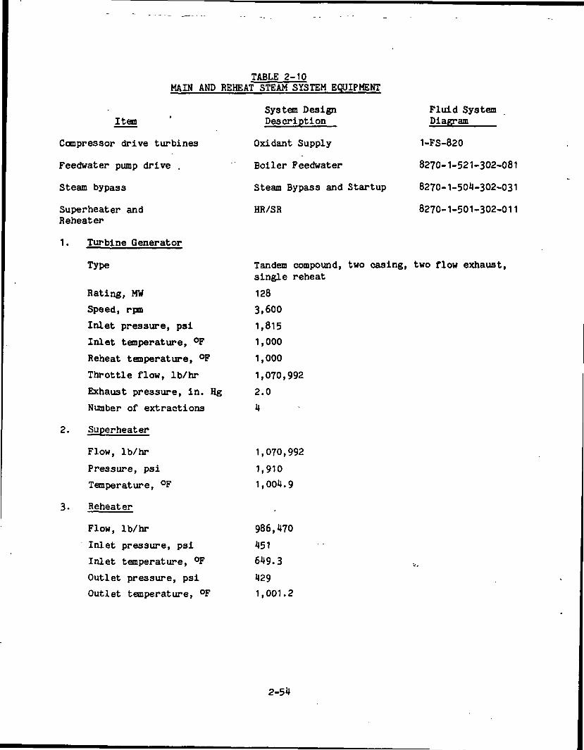
TABLE 2-10MAIN AND REHEAT STEAM SYSTEM EQUIPMENT
Item
Compressor drive turbines
Feedwater pump drive .
Steam bypass
Superheater andReheater
1. Turbine Generator
Type
Rating, MWSpeed, rpmInlet pressure, psi
Inlet temperature, °FReheat temperature, °FThrottle flow, Ib/hr
Exhaust pressure, in. HgNumber of extractions
2. Superheater
Flow, Ib/hr
Pressure, psiTemperature, °F
3. Reheater
Flow, Ib/hrInlet pressure, psi
Inlet temperature, °FOutlet pressure, psiOutlet temperature, °F
System DesignDescription
Oxidant Supply
Boiler Feedwater
Steam Bypass and Startup
HR/SR
Fluid SystemDiagram
1-FS-820
8270-1-521-302-081
8270-1-504-302-031
8270-1-501-302-011
Tandem compound, two casing, two flow exhaust,single reheat
128
3,600
1,8151,000
1,000
1,070,992
2.0
4
1,070,992
1,910
1,001.9
986,470
451
649.3
4291,001.2
2-54

2.5.5.1.3 Modes of Operation
1. Startup
During the startup sequence, mismatches occur in component temperatures. Ifsignificant temperature differences exist between the HR/SR, steam turbine andthe steam transfer piping, thermal stresses exist that are capable of damagingthe equipment. To eliminate this possibility, conditions (e.g., temperatures)compatible with normal operation have to be achieved by the startupprocedures. The procedure that will ensure satisfactory startup includes thefollowing steps.
a. Cleanup of feedwater cycle to acceptable purity conditions.
b. HR/SR filled and vented to startup drum level.
c. Operational boiler feed, condensate, and circulating water systems.
d. The main steam turbine is placed on turning gear and is rollingprior to admitting gland sealing steam and establishing a vacuum.
e. Auxiliary Steam System is functional for initial deaeration, turbineseals, and for system warmup.
f. Main condenser vacuum is established as low as possible, but nogreater than 5.0 inches Hg.
g. When main steam pressure reaches 200 psig minimum, the stop valvebypasses are opened to initiate prewarming the HP turbine casing,reducing turbine thermal stresses. This is done while the turbineis on turning gear. Throughout the turbine prewarming operation,turbine casing metal and differential temperatures are monitored,recorded and maintained according to the limits set by the turbinemanufacturer.
h. During HR/SR warmup operation, boiler blowdown is monitored to checkacceptable solids concentration levels. Steam piping is warmed,with all drains opened, as steam pressure increases.
i. The following turbine metal temperatures are recorded prior toinitial roll off turning gear:
First stage shell inner surfaceFirst stage shell outer surfaceFirst reheat bowl inner surface
j. The turbine is rolled off turning gear when the inlet steamconditions at the turbine throttle valves are approximately 600 psigwith 100°F of superheat. This will provide optimum uniform heatingand differential expansion rates dictated by the turbinemanufacturer.
2-55
k. The turbine is accelerated to a rotor warming speed and maintaineduntil the unit is satisfactorily pre-warmed. Acceleration may thencontinue to 3,600 rpm, and the turbine synchronized and loaded.
2. Normal Operation
The normal load range of the overall plant is categorized as base load with asmall percentage part load operation below 75 percent. The plant is capableof operating satisfactorily and with no special operator action in the eventof small load changes. During normal operation the overall plant iscontrolled and monitored from the main control room. Should the load go below75 percent, administrative action would be required to decide: Whatpercentage of the load the topping side or bottoming side would share; whetherthe bypass system should be initiated; whether the turbine and steam pipingdrains are to be opened; or if the unit should be tripped.
The normal load range of the main and reheat steam system is categorized asbase load with a small percentage part load operation below 75 percent.Should the unit be operated below this level, administrative action will beprovided to ensure that drain valves will be opened at 25 percent and lowerload ratings. Also the steam bypass system may be activated at 50 percent orlower steam flow to the main turbine. The system is capable of operatingsatisfactorily and without special operator action in the event of load changeon the unit. During normal operation, the system is controlled and monitoredfrom the main control room.
3. Shutdown
For operator-initiated shutdown, the unit load is reduced to minimum, and theturbine is tripped. The electromatic valve may be used for venting. This isdone by selecting the "Manual" position on the control room selector switch.
During the shutdown process, the main steam and reheat piping startup drainsare opened to drain all moisture from the steam lines.
In a normal, controlled shutdown, the steam line drain valves open at about20 percent turbine generator load. No other operator action is required. Ona.turbine generator trip the stop valves in the steam leads and the non-returnvalves in the extraction lines close automatically. Operator attention isrequired to confirm operation of these valves.
During long periods of shutdown, the HR/SR and main steam piping are blanketedwith nitrogen to reduce the formation of corrosion products which can causeincreased maintenance problems.
2.5.5.2 Steam Bypass and Startup
The steam bypass and startup system permits 50 percent of full-load steam flowto bypass the main turbine to the main condenser during plant operation.During startup the system allows steam flow to be established quickly throughthe reheater to facilitate turbine - steam temperature matching. Arrangementand equipment are depicted on Fluid System Diagram 8270-1-501-302-031.
2-56
Two stages of bypass are involved. A high pressure bypass conveys steam fromthe superheater steam header to the cold reheat header, and a low pressurebypass routes steam from the hot reheat header to the main condenser.Desuperheating water for the high pressure bypass stage is taken from theboiler feedwater pump discharge and from the main feedwater pump interstagebleed for the intermediate pressure stage. Both stages of bypass areinterlocked so that steam cannot be bypassed if desuperheating spray isunavailable. In addition, bypass to the condenser will be stopped ifcondenser pressure is too high.
During a cold or warm startup the set-point pressure of the high pressurebypass pressure valves are regulated to match generated steam pressure. Withbypass flow established through the reheater, the turbine temperature rate-of-increase is matched to steam temperature rate of increase. This minimizestime to reach turbine synchronization and loading.
2.5.5.3 Extraction Steam
Steam is extracted from, four points of the main turbine and used forregenerative feedwater heating. The highest pressure extraction point is atthe high pressure turbine exhaust which provides cold reheat steam tofeedwater heaters 1A and 4B (see Fluid System Diagram 8270-1-503-302-011 forschematic arrangement of Extraction Steam system equipment). There are twoextraction points in the intermediate pressure turbine section; one suppliessteam to feedwater heaters 3A and 3B, and the second supplies steam tofeedwater heaters 2A and 2B. One extraction from the low pressure turbinesupplies steam to the deaerator.
In the event of a turbine trip, the turbine is protected from overspeed bypreventing reverse flow of flash steam from the heaters with positive closing,balanced disc, non-return valves located in the extraction lines. The valvesare located in horizontal piping runs close to the turbine. To prevent waterfrom entering the turbine stages, motor-operated gate valves are installed inthe extraction lines to close automatically if a high water level is sensed inthe heaters. These valves are locked in the closed position until the levelmonitor indicates normal water level.
The steam extraction system is a base load system, designed for operation at75 to 100 percent of rated load. No special operator action will be requiredfor cycling except opening of drain valves at loads below 25 percent.
2.5.5.1 Condensate
The condensate system conveys the condensed steam from the condenser hotwellthrough the steam seal exhauster-condenser, steam jet air ejector condensers,demineralizer, and into the deaerating heater. Flow and arrangement are shownon Fluid System Diagram 8270-1-511-302-101.
2.5.5.1.1 Flow Description
Exhaust steam from the low pressure turbine and the boiler feedwater turbinesexhausts directly into the main condenser. The two oxidant compressor drives
2-57
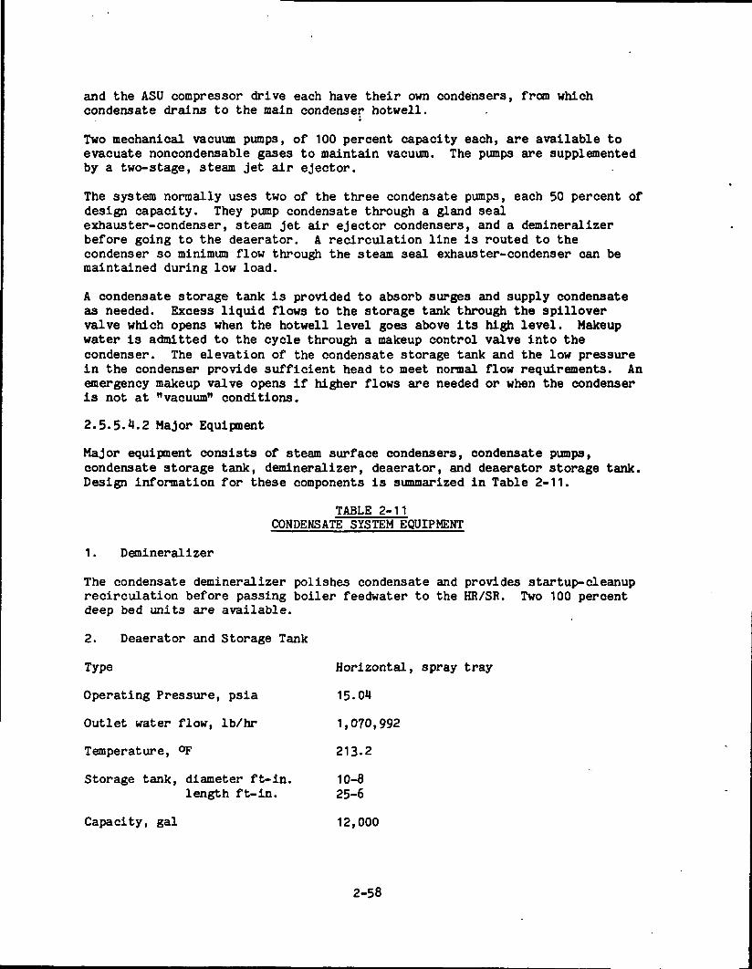
and the ASU compressor drive each have their own condensers, from whichcondensate drains to the main condenser hotwell.
Two mechanical vacuum pumps, of 100 percent capacity each, are available toevacuate noncondensable gases to maintain vacuum. The pumps are supplementedby a two-stage, steam jet air ejector.
The system normally uses two of the three condensate pumps, each 50 percent ofdesign capacity. They pump condensate through a gland sealexhauster-condenser, steam jet air ejector condensers, and a demineralizerbefore going to the deaerator. A recirculation line is routed to thecondenser so minimum flow through the steam seal exhauster-condenser can bemaintained during low load.
A condensate storage tank is provided to absorb surges and supply condensateas needed. Excess liquid flows to the storage tank through the spillovervalve which opens when the hotwell level goes above its high level. Makeupwater is admitted to the cycle through a makeup control valve into thecondenser. The elevation of the condensate storage tank and the low pressurein the condenser provide sufficient head to meet normal flow requirements. Anemergency makeup valve opens if higher flows are needed or when the condenseris not at "vacuum" conditions.
2.5.5.4.2 Major Equipment
Major equipment consists of steam surface condensers, condensate pumps,condensate storage tank, demineralizer, deaerator, and deaerator storage tank.Design information for these components is summarized in Table 2-11.
TABLE 2-11CONDENSATE SYSTEM EQUIPMENT
1. Demineralizer
The condensate demineralizer polishes condensate and provides startup-cleanuprecirculation before passing boiler feedwater to the HR/SR. Two 100 percentdeep bed units are available.
2. Deaerator and Storage Tank
Type Horizontal, spray tray
Operating Pressure, psia 15.04
Outlet water flow, Ib/hr 1,070,992
Temperature, °F 213.2
Storage tank, diameter ft-in. 10-8length ft-in. 25-6
Capacity, gal 12,000
2-58

3. Condensers
MainTurbine Generator &BFW Pump Turbines
Number
Surface, sq. ft.
Tube material
Tube Size, in OD-BWG
Tube Length, feet
Water, gpm
Water Temp, in, °F
Water Temp, out, °F
Pressure, in. Hg abs.
4. Condensate Pumps
Type
Number
Capacity, gpm
Head, feet
1
57,000
Copper-nickel
7/8 - 18
25
51,200
69
92
2.0
OxidantComp. Turbines
2
7,600
Copper-nickel
. 7/8 - 18
20
8,500
69
92
2.5
ASUComp. Turbine
1
8,000
Copper-nickel
7/8 - 18
20
8,900
69
92
2.5
Vertical, centrifugal, multi-stage
Three
950
200
Net Positive Suction Head (NPSH), feet 10
Brake horsepower 75
2.5.5.4.3 Modes of Operation
1. Startup
The condensate system is one of the first systems to be placed in operationduring plant startup. The system supplies cooling water to the steam sealexhauster, sealing water to main feedwater pump seals, boiler fill water andmiscellaneous condensate services.
Startup from a "dry" state involves the filling of the condenser hotwell andthe HR/SR. The condenser hotwell is filled by opening the fill valve at themain condenser and admitting water from the condensate storage tank. Afterthe hotwell is filled, the condensate pumps are started and the condensatesystem, from the condenser to the main system shutoff valve and bypass line,is vented and filled. Once flow is established through the bypass line, thefeedwater system may be started and the HR/SR filled.
2-59
For normal startup, after the HR/SR and condenser hotwell are filled, the nextstep is to vent and fill the con dens ate system. The condensate pumps arestarted with main system shutoffs closed and the control valves open. Withthe lower flow through the empty system, system fill is accomplished withoutcausing severe water hammer. After the condensate system is filled andvented, the plant cleanup cycle can begin.
During the turbine waraup cycle with the main turbine on turning gear, sealingsteam is supplied to the turbine glands, the condenser vacuum pumps arestarted, the steam sparger in the deaerator is turned on, and the condensateis recirculated until the oxygen content and the pH are within prescribedlimits.
The level in the condenser hotwell is maintained by the static height of thestored water in the condensate storage tank. One set of controls governs theamount of makeup or dump required. The discharge from the condensate pumpspasses through the steam seal exhauster and a blowdown cooler, and then to thedeaerator. The system requires no operator action after startup, exceptnormal surveillance. The system head floats on the system curve, depending onload. The temperature of the condensate from the deaerator is dependent onturbine loading.
2. Normal Operation
The unit, and consequently the condensate system, is normally operated at fullload, with a small percentage of part load operation between 75 and 100percent.
The condensate system is capable of operating satisfactorily and with nospecial operator action in the event of load changes on the unit.
The standby condensate pump is arranged for automatic start on an electricaltrip of a running pump.
3. Shutdown
Equipment may be removed from service by closing isolation valves and openingbypass valves (except the seal steam exhauster-condenser) in accordance withoperating instructions provided by the equipment manufacturer.
A high-high water level in the deaerator storage tank or low water level inthe main condenser hotwell causes closure of the deaerator inlet isolationvalve. A very low condenser hotwell level will cause a trip of the condensatepumps.
Two condensate pumps must be kept in service until the condensate/feedwaterflow requirement has fallen below 50 percent of full load, and must remain inoperation on recirculation until the gland seal exhauster-condenser isshutdown. The Condensate and Boiler Feedwater Systems must be in operationwhenever hot gases are flowing through the Topping cycle.
2-60
4. Special or Infrequent Operation
The condensate system valves and controls are designed to prevent waterinduction and steam reverse flow from entering the main steam turbinefollowing a turbine trip. A high feedwater level in the deaerator divertsincoming drains directly to the main condenser. A high-high level closes thenon-return valves and the stop valve and opens the extraction piping drainvalves. This effectively removes the deaerator from the system and preventswater induction into the main steam turbine.
During a steam dump to the main condenser, the Condensate System may beaffected by a deterioration in vacuum, an increase in condensate temperature,and a fluctuation of level in the condenser hotwell.
2.5*5.5 Boiler Feedwater
The boiler feedwater system supplies the fluid that is converted to steam inthe HR/SR. Feedwater is used for cooling the MHD Power Train and the flue gasis exhausted from the stack. Flow paths and arrangement are depicted on FluidSystem Diagram 8270-1-521-302-081.
2.5.5.5.1 Flow Description
Two booster pumps, each of 100 percent capacity, are available for thefeedwater transport from the deaerator storage tank to the suction of theboiler feed pumps. These pumps are located 35 feet below the level of thetank to ensure adequate net positive suction head (NPSH). Discharge from thebooster pump is through the channel coolant loop, the low temperatureeconomizer, and to the suction headers of the boiler feedwater pumps.
Boiler feedwater pumps, two 50 percent turbine-driven pumps operating atnormal load and a reserve 50 percent variable-speed motor driven pump,transport the feedwater through the feedwater heaters, the high temperatureeconomizer, the MHD power train (except channel), and in to the HR/SR steamdrum.
Boiler feedwater purity is monitored continuously and sampled to ensure thatrequired quality is maintained.
2.5-5.5.2 Major Equipment
Flow rates and conditions shown for the major equipment are for base loadoperation as indicated on System Heat'and Mass Balance Drawing No. 8270-1-5 0-314-001. The equipment includes the booster pumps, feedwater pumps anddrives, and feedwater heaters. Design information for these components issummarized in Table 2-12.
2-61
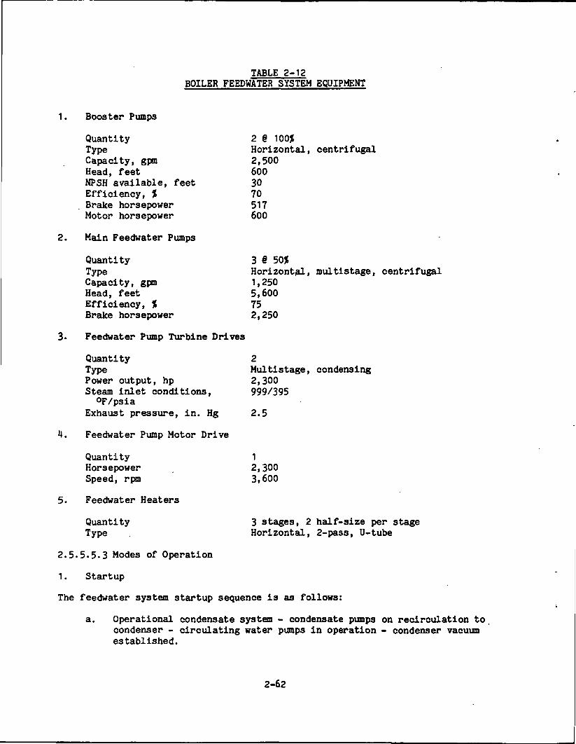
TABLE 2-12BOILER FEEDWATER SYSTEM EQUIPMENT
1. Booster Pumps
Quantity 2 § 100$Type Horizontal, centrifugalCapacity, gpm 2,500Head, feet 600NPSH available, feet 30Efficiency, % 70Brake horsepower 517Motor horsepower 600
2. Main Feedwater Pumps
Quantity 3 6 50$Type Horizontal, multistage, centrifugalCapacity, gpm 1,250Head, feet 5,600Efficiency, % 75Brake horsepower 2,250
3- Feedwater Pump Turbine Drives
Quantity 2Type Multistage, condensingPower output, hp 2,300Steam inlet conditions, 999/395
QF/psiaExhaust pressure, in. Hg 2.5
4. Feedwater Pump Motor Drive
Quantity 1Horsepower 2,300Speed, rpm 3,600
5. Feedwater Heaters
Quantity 3 stages, 2 half-size per stageType Horizontal, 2-pass, U-tube
2.5.5.5.3 Modes of Operation
1. Startup
The feedwater system startup sequence is as follows:
a. Operational condensate system - condensate pumps on recirculation tocondenser - circulating water pumps in operation - condenser vacuumestablished.
2-62
b. System is aligned for normal operation; i.e., necessary valves arein proper position, and system is filled and vented. (With thedeaerator at normal level the system may be filled by gravity andvented prior to any pump start.)
c. Auxiliary steam available for sealing turbine, pegging deaerator,etc.
d. Deaerator storage tank level at normal operating point. Deaeratorpegged and vented at 2 psig by use of auxiliary steam.
e. Booster pump minimum flow recirculation valves open.
f. A feedwater booster pump is started and cleanup recirculation isestablished through the booster pump discharge and back to thecondenser.
g. Feedwater flow is established through the heater and bypass piping.Flow is alternated as necessary to flush each route. This flush isdumped to the condenser from a point upstream of the hightemperature economizer inlet. This flow path is used to clean upand deaerate the water prior to sending the water to the HR/SR. Thewater is satisfactorily clean for introduction to the radiant boilerwhen (1) differential pressure has stabilized across a clean suctionstrainer, and (2) water chemistry has reached satisfactory levels.
h. The motor-driven feedwater pump is started and recirculation isestablished through the pump recirculation system back to thedeaerator. Booster pump cleanup line to the condenser must beclosed prior to starting the main .pump.
i. The MHD power train is fired at this point using the vitiated airheater to start generation of steam in the HR/SR radiant boiler.
J. When boiler drum conditions reach adequate pressure and temperature,main steam may be used for the turbine shaft seals and to operate aturbine-driven feedwater pump in accordance with the startingrequirements of the HR/SR and the main turbine.
k. As the MHD system combustor is fired to increase HR/SR steamtemperature and drum metal temperature in accordance with prescribedrates, the steam piping and the main turbine casings are warmed.
1. When unit megawatt load exceeds 10 percent, a second turbine drivenmain feed pump is brought into service, and pump speeds areparalleled. The motor driven pump may be put on standby wheneverthe system pumping capacity is satisfied by the turbine drivenpumps.
2-63
2. Normal Operation
During normal operation of the feedwater system, the system is controlled andmonitored from the main control room. Booster pumps and all valve motors areoperated from control switches located on the feedwater-condensate panel ofthe main board.
3. Shutdown
Continuous feedwater delivery is required to maintain boiler drum level andflow through the MHD power train while bringing the plant to a shutdown.
M. Special or Infrequent Operation
A complete loss of feedwater flow to the boiler could occur if power is lostto the feedwater booster pumps. This will cause a plant shutdown. Loss ofcondensate pumps will result in a forced shutdown unless restored withinapproximately 5 minutes (deaerator storage tank capacity). On loss of onemain feedwater pump, automatic load reduction will commence while the standbymotor-driven pump starts to restore flow. Loss of a booster pump will causeautomatic reduction of the main feedwater pumps until the standby booster pumpcan be started and brought up to speed. Low suction pressure willautomatically trip the main feedwater pumps.
A feedwater heater string may be removed from service by opening the bypassline and closing the inlet and outlet valves on the heater string to beisolated. Load is reduced in accordance with the turbine manufacturer'sinstructions.
2.5.5.6 Feedwater Heater Drips
The feedwater heater drips system maintains normal water levels in thefeedwater heaters and controls flow of condensate to the deaerator. Inperforming these services the system functions to prevent liquid water surgesto the turbine blading stages. Drip control flow cascades from the higherextraction pressure feedwater heaters to the lower and then to the (lowpressure) flash tank. Steam from the flash tank flows to the deaerator.During startup or in the event of high water level the feedwater heaters candrain directly to the main condenser. Arrangement and flow paths are shown onFluid System Diagram 8270-1-525-302-111.
There are three stages of closed feedwater heaters in two parallel loops of 50percent capacity. Thus stages 2A, 3A, and 4A are in series and 2B, 3B, and MBare in series. The first stage of heating is in the deaerator. The heaterscascade normally from full load to 20 percent load. At startup, below 20percent load, and in an emergency (operational malfunction) each heater has analternate drain to the main condenser. In the event of turbine trippositively actuated non-return extraction valves close automatically toprevent flashed steam from flowing in reverse through the extraction steampiping and impacting on the turbine blades.
2-64
ORIGINAL PAGE ISOF POOR QUALITY
2.5.5.7 Feedwater Heater and Miscellaneous Drains, Vents and Reliefs
The feedwater heater vents, drains and reliefs system provides draining andventing of the feedwater heaters to the main condenser. Miscellaneous drainsconvey condensate drains from the following steam lines to the main condenser:
HP Turbine Main Steam (2 lines)HP Turbine exhaust (2 lines)Cold Reheat • 'Extraction Steam to Feedwater Heaters MA 'and IB (2 lines)Hot Reheat Steam to IP Turbine (2 lines)Extraction Steam to Feedwater Heaters 3A and 3BExtraction Steam to Feedwater Heaters 2A and 2BIntermediate Pressure to Low Pressure Cross OverDeaeration Extraction SteamHot Reheat Steam to Boiler Feed Pump TurbinesHot Reheat Steam to Oxidant TurbineHot Reheat Steam to ASU Turbine
Flows and arrangements are shown on Fluid System Diagrams 8270-1-525-302-113and 8270-1-519-302-121.
2.5.5.8 Condenser Air Removal
The condenser air removal system removes non-condensable gases from the steam,space of the main and oxidant system surface condensers. Gases are removed bymeans of a steam jet air ejector (SJAE) and rotary vacuum pump systems anddischarged to the atmosphere. Flow arrangement is shown on Fluid SystemDiagram 8270-1-491-302-131.
Each surface condenser has an air removal line in each water box (divided).These lines exhaust to a common header from which separate lines go to theSJAE and two 50 percent capacity vacuum pump systems. During normal operationthe SJAE is used for holding vacuum or as a backup to the pumps in the eventof air surges. For low absolute pressures (high vacuum) the vacuum pumpsoperate in series with automatically controlled air ejectors. , This airejector, which employs an air jet, acts as a hogger during startup and toreduce pressure surges due to excess non-condensables in the steam exhaustedto the condensers.
For normal operation, one pump system operates while the other is on standby.The standby pump system starts automatically if the set level of pressureincreases (vacuum decreases).
The condenser air removal system must be operative before startup of thecondensing turbines. Gland steam sealing pressure can be established by theoperator through use of the auxiliary boiler steam supply.
2.5.5.9 Circulating Water
The Circulating Water System supplies cooling water for the main and auxiliarycondensers and for power plant heat exchangers. Arrangement and flow patternsare shown on Fluid System Diagram 8270-1-571-302-201.
2-65
Circulating water, after extracting heat from the plant condensers and heatexchangers, is pumped to the top of the cooling tower. From there it issprayed over cooling tower trays and it flows downward through the stagedtrays to the tower basin. Air enters horizontally at the bottom of the towerby induced draft and flows through the falling water. Since cooling isprimarily by evaporation, the wet bulb temperature of ambient air is theimportant parameter.
Cooled water in the basin flows through the flume and screens to the suctionof vertical circulating water pumps which discharge water to the plantcondensers. Separate service water pumps are provided to pump circulatingwater through plant heat exchangers.
The cooling towers are mechanical draft, cross-counter flow type arranged intwo parallel flow units each with four cells. Each cell is an entity coolingunit with its own structure, tray stages, water pipe headers and top mountedfan. During plant operation in cold weather, a portion of the heatedcirculating water is bypassed around the cell to prevent icing. Each cell canbe isolated for service and full load can be maintained with one cell out ofservice.
All pumps are vertical mixed-flow type. The pressure developed is primarily afunction of the height above the tower basin to the top of the tower for waterlift. Flow friction through piping and heat exchangers at maximum flow areother major design criteria for sizing the pumps. Pump discharge valves areinterlocked with the pump motors so that pump startup occurs at apredetermined valve opening point. Motor and valve interlocks prevent thepump from being run in reverse. In the anticipated event of large steam dumpto the condenser, the operator may place all cooling tower cells in operationto help remove the excess heat load.
2-66
2.5.6 Plant Auxiliary Systems
2.5.6.1 Auxiliary Steam
The Auxiliary Steam System will provide up to 200,000 pounds per hour of115 psi, 350°F steam for plant heating and for auxiliary services duringstartup and plant operation. Utilization areas are:
Building heating.Flue gas sampling.Steam coil air preheater.Fuel oil burners.Turbine gland sealing (startup and standby).Main deaerator and storage tank.Auxiliary deaerator sparging system.Condensate demineralizers.Compressor drive turbine wanning.Steam coil supply.Auxiliary boiler deaerator supply.
Arrangement•and flows are shown on Fluid System Diagram 8270-1-507-302-501.
The two auxiliary boilers are oil-fired, natural circulation, packaged unitswith a maximum continuous rating of 100,000 pounds per hour, each.
During startup of the power system, the auxiliary boilers provide steam forair preheating, oil burner atomization, to warm and deaerate the condensate/feedwater, and to provide other auxiliary warming and pegging steam as needed.
2.5.6.2 Boiler Flue Gas System
The Boiler Flue Gas System provides the ducting and components fortransporting boiler flue gas from the HR/SR boiler to the ESP and to variousbottoming side components, such as the low temperature economizer, theafterburner gas supply air heater, and the coal pulverizing mills. Thearrangement of system components (excluding the HR/SR boiler and the ESP) andthe connecting ductwork are shown schematically on Fluid System Diagrams8270-1- 103-302-301, 8270-1-403-302-322, and 8270-1-403-302-323-
The 480°F flue gas from the HR/SR boiler flows into the ESP at the rate of1.35 millions pounds per hour and 14,649 pounds per hour of ash/seed mixtureare removed during 100 percent normal power operation. The cleaned flue gasfrom the ESP is then split into multiple streams as required for the followingsubsystem functions:
1. Coal Drying and Transport Gas (Fluid System Diagram 8270-1-403-302-323)
Flue gas at a rate of 564,000 pounds per hour is conveyed by two50 percent capacity blowers to the pulverizer mills for coal drying andtransport to the coal processing baghouse. The coal fines are removedfrom the flue gas in the baghouse and the cleaned gas is returned to the
2-67
intake of the induced draft fans for discharge to the atmosphere via thestack. After passing through the afterburner gas supply air heater,5500 pounds per hour of flue gas are directed to the transport gascompressors where the gas is pressurized and used for transporting thecoal from the pressurized lock hoppers to the combustion.
2. Afterburner Gas Supply
The air heater is supplied with 225,000 pounds per hour of 480°F flue gasfor heating the 205,000 pounds per hour of secondary combustion air thatis directed to the afterburner section of the HR/SR. Flue gasrecirculation is established by the addition of 106,000 pounds per hourof 480OF flue gas to the heated secondary combustion air which producesthe total flow of 311,000 pounds per hour of afterburner gas supply tothe HR/SR. The flue gas exhaust from the air heater is directed to theinduced draft fans for discharge to the atmosphere.
3. Low Temperature Economizer
The remaining 438,000 pounds per hour of flue gas from the ESP flowsthrough the low temperature economizer providing 5.5 MWt of heat transferto the boiler feedwater. The flue gas is then exhausted to the induceddraft fans.
All of the returned flue gas streams with a combined total flow of1,259 million pounds per hour are directed to the intake header for theinduced draft fan. Two of the three induced draft fans (50 percent capacityeach) discharge the cleaned flue gas to the atmosphere via a 300 foot highstack.
2.5.6.3 Coal Management
Coal management consists of the following functions:
Receiving and unloadingStoringScreening and crushingPulverizing and dryingPressurized storageInjection to the combustor
2.5.6.3.1 Yard Coal Handling
At full load the ETF will require 101.8 tons of raw coal per hour. However,during the first 24 months of operation, the plant is expected to be in a testphase wherein full load will be maintained for 2,000 hours per year, or a23 percent capacity factor. During this period, coal requirements will be206,000 tons per year. Full load commercial operation at a 70 percentcapacity factor requires an annual coal supply of 624,000 tons. Using thelatter basis, the coal yard storage is sized for a 60 day supply. DrawingsNo. 8270-1-240-002-001 and 8270-1-240-002-002 show the yard coal handlingarrangement.
2-68
1. Rail Car Unloading
The coal unloading and storing facility located in the northwest cornerof the plant is 800 feet long and 500 feet wide. A thawing process forrail cars is provided for winter handling of coal. As an additionalmeasure, a Freeze Control Agent (FCA) with glycol based compounds may beused to weaken the crystalline structure of ice. The FCA would besprayed on coal at a cascade point on the coal belt conveyor at the mineor after the coal is loaded in the train.
A rotary dumping rail unloading system is provided. The system requiresa minimum of 3-1/2 to 4 hours for thawing and unloading a unit train with100 cars. Gondola type cars of random size up to 100 ton capacity can beaccommodated without adjustment or loss of cycle time using the unittrain concept. This is accomplished by the use of cars with rotarycouplers and approximately three miles of track around the perimeter ofthe site.
The 100 feet long (8 car-length) thawing shed equipped with infraredelectric heaters is located at the coal unloading facility. The averageelectrical power consumption for the thawing shed is about 7,000 kH. Thethawing shed is divided Into 8 zones of 50 feet each. The first fourzones from the approach end are utilized as thawing bays equipped withheaters, and the remaining four zones as soaking bays without heaters.Special care is required to avoid stress and damage to the cars due tooverheating.
After a car has proceeded through the thaw shed, it enters a hydrauliccar positioner unit. Locomotives are used only to spot the train for theinitial stop in the thaw shed. After that, all train motion iscontrolled by the car positioner. The positioner unit consists of twohydraulic rams, one located on each side of the tracks. Each ram has twocarriage arms, one for acceleration and one for deceleration.
Once the coal car has been positioned it is ready for weighing anddumping. Scales located before and after the rotary car dumping devicerecord the loaded car weight (gross) and the empty car weight (tare) foreach car. Normally, a rotation of 160 degrees is used for dumping;however, 180 degrees maximum rotation can be utilized if required. Eachcar is furnished with rotary couplers to enable dumping withoutdisengagement. Two electric eyes detect any misaligned cars and willprevent dumping in such an event. As car rotation begins, four hydraulicclamps engage the top of the car. Limit switches monitor the clampingand stop the rotation if secure clamping has not been obtained.
The coal is dumped into a 300 ton-capacity unloading hopper located60 feet below the dumper. Above the hopper a bar screen with 12 inchopenings and runway space for a small tractor-dozer is provided to breakup large or frozen chunks of coal to avoid blockage or damage to thedownstream coal handling equipment. The hopper is constructed of1/1 inch thick steel plate with a 1/8 inch thick stainless steel liner.Four outlets, with slide gates, direct the coal into four reciprocating,
2-69
plate type, vibrating feeders each rated at 1,000 tons per hour. Thesefeeders discharge onto the short 54 inch wide belt (No. 1 conveyor),which in turn discharges through a chute onto a long 54 inch wide beltconveyor No. 2. Belt conveyor No. 2 is a long belt transporting coalfrom underground to the sample house and to the transfer tower. Beltconveyors No. 1 and No. 2 are each rated at 1,750 tons per hour, 450 feetper minute.
2. Storage Bunker
At the sample house, the physical and the chemical properties of coalwill be tested. The transfer tower is equipped with a mechanical dustcollector and coal sampling equipment. The transfer surge bin has twoconical discharge chutes with the openings controlled by power actuatedslide gates. From these two chutes, the coal can be diverted to two54 inch wide belt conveyors No. 3A and 3B. These conveyors are rated at1,750 tons per hour, 450 feet per minute and deliver coal into the top oflowering wells which establish active coal piles. Excess coal is movedto long term storage and packed down by rubber tired dozers and bulldozerscrapers. There is 30 days storage in each of two long term piles. Eachcoal pile is equipped with a lowering well.
Four vibrating feeders and four hoppers are located below grade in aconcrete trench in line with each lowering well. The vibrating feedersdump the coal into 42 inch wide belt conveyors No. 4A and No. 4B rated at1,000 tons per hour, 450 feet per minute.
Belt conveyors No. 4A and No. 4B pass through weigh scales which monitorthe tonnage of coal in transit and transmit the data to the stationcontrol room. The station operator (upon advice from the chemist) canvary the feeder rates to obtain the required quality of the coal byblending coals from each of the two piles. Belt conveyors No. 4A andNo. 4B feed a 500 ton surge bin located in the control transfer house.The bin feeds two crushers rated at 500 tons per hour and takes therun-of-mine coal down to 1-1/2 inch size or less which is suitable forthe pulverizers. From the two crushers, coal is fed by gravity to two30 inch wide belt conveyors No. 5A and No. 5B, rated at 500 tons perhour, 450 fpm. The control transfer house is also equipped withmechanical dust collecting equipment.
3, Coal Transport System
Belt conveyors No. 5A and No. 5B feed into a 2,000 ton storage capacitybunker at an elevation of 150 feet via the coal tripper. This tripper israted at 500 tons per hour, and can be fed by either belt conveyor No. 5Aor No. 5B. The bunker is suitable for 16 hours of storage and isequipped with a dust suppression system. From the storage bunker, thecoal is fed by large diameter pipes into weigh-feeders which measure anddistribute the coal to two of the three 55 tons per hour capacitypulverizers. One of the pulverizers acts as a spare. To reduce coaldust problems, a slight negative pressure will be maintained in the coalpreparation building by induced draft fans equipped with high efficiencydust collectors.
2-70
For coal drying in the pulverizer, approximately 564,000 pounds per hourof flue gas (2.75 pounds of gas per pound of as-received coal) is tappedfrom the main gas stream between the ESP and the low temperatureeconomizer. In the pulverizer, coal is dried to 5 percent moisture byweight and pulverized to 70 percent-200 mesh size. At design capacity,the ETF plant consumes 83 tons per hour of dried coal. The mixture ofpulverized coal and wet flue gas is separated in a baghouse, where thecoal is collected and transported to four 150 ton capacity (each) coallock hoppers. The flue gas is discharged to the stack.
2.5.6.3.2 Coal Feed Lock Hoppers
The dried pulverized coal is transferred through pneumatic valves and feedersto two depressurized 150 ton capacity (each) lock hoppers (A1 and A2), asshown on Fluid System Diagram 8270-1-410-302-341. At the same time, the othertwo pressurized lock hoppers (B1 and B2) are feeding coal to the continuouslypressurized primary injector B. All the slide gate valves are supplied withseal air. All the lock hoppers and primary injectors are pressurized with drynitrogen at startup and then switched to flue gas (at a minimum pressure of72 psia). The coal feeding to the primary injector takes place withoutinterrupting the continuous injection of coal from the primary injector to thecombustor. The lock hopper and primary injector are stacked. All the lockhoppers and primary injectors have a rupture disc with bag filters on thedischarge to release overpressure to the atmosphere. Approximately one poundof high pressure gas transports 30 pounds of coal from the primary injector tothe coal feeder header located around the first stage of the combustor. Apressure differential controller balances the air pressure between the primaryinjector outlet and the coal feed line. The signals from the combustor burnercontrol system regulate the speed of the coal feeder and the flow of the highpressure transport gas to the combustor. Drawing No. 8270-1-410-302-341 showsthe coal feed lock hopper arrangement.
2.5.6.4 Seed Management
The Seed Management System receives and unloads fresh seed; recovers spentseed from the HR/SR boiler and ESP; conveys, stores, pulverizes, mixes andinjects prescribed fractions of fresh and spent seed into the MHD combustor;and trucks spent seed to an off-site location for either reprocessing ordisposal.
2.5.6.4.1 Yard Seed Handling
Drawings 8270-1-240-002-003 and 8270-1-240-002-004 show plan/section views ofthe fresh seed unloading and storage area. Potassium carbonate (KgCOj) isdelivered to the plant by sealed cars. Approximately 100 tons per day offresh seed is poured into receiving pits, and moved from there to the 10 daystorage silo by screw conveyors.
The seed unloading facility is located on a rail line next to the seed feedbuilding and is provided with an unloading shed to keep the K2C03 from pickingup moisture.
2-71
The spent seed, which is primarily potassium sulfate ( SOij), is trucked fromthe spent seed and fly ash silos to the storage area. The potassium carbonateand recycled potassium sulfate are stored in separate silos which are providedwith screw conveyors. Each screw conveyor is designed for 75 tph delivery and20 tph reclaim rate. The silos are sized for a minimum storage time of10 days for K2C03 and 5 days for K2SOi| at full load.
2.5.6.4.2 Seed Feed Lock Hoppers
The equipment of the Seed Feed System processes seed from the storage silosfor injection into the MHD combustor. This equipment is shown on Drawing8270-1-410-302-342 and is located in the Seed Feed Building, Building 35, ofDrawing 8270-1-210-007-001.
Fresh and recycled seed are reclaimed by screw conveyors from the £3003 andK2SOii storage silos and conveyed to the K2C03 and K2SOij reclaim hoppers. TheK2C03 and K2SOij flows are metered and pulverized separately and mixed at theoutlet of the pulverizers.
Between the pulverizers and the combustor, all seed feeding equipment is induplicate and interconnected for switchover. Seed from the metering bunker tothe pulverizers is regulated by the feeders. The pulverizers are speciallydesigned to pulverize seed along with a small fraction of slag, and grind topass at least 70 percent through a 200 mesh screen. The transport air fromthe air dryer is used to transport pulverized seed to the cyclone collectorsoperating at atmospheric pressure.
The cyclone collectors, 50 ton capacity, lock hoppers and primary injectorsare stacked vertically. Dry air is provided at the bottom of the lock hoppersand primary injectors to avoid plugging the outlets. High pressure oxidanttransports seed from the primary injector to the water cooled seed inletlocated near the combustor exit (see Drawing SDD-1101, of SDD- 502). Theoxidant leaves the oxidant compressor outlet at a temperature of 433°F.
2.5.6.4.3 Ash/Seed Removal from Power System
Seed is collected from the downstream end of the convective section of theHR/SR boiler and from the ESP. A small fraction of ash is collected with theseed at these locations. No attempt is made to recover the small fraction ofseed chemically combined with the Combustor and Radiant Boiler slag.
Hot dry seed is collected from the HR/SR convective section and the ESP via ahigh temperature hopper/feeder system, and is conveyed to the Spent Seed andFly Ash Silos (Item 19 of Drawing 8270-1-210-007-001). From these silos, thefraction of spent seed that is to be recycled is shipped by truck to the SeedUnloading Facility (Item 37 of Drawing 8270-1-210-007-001). The remainingfraction is trucked off-site for either reprocessing or sale. Equipment forspent seed collection is shown on Drawing 8270-1-451-302-352.
2-72
2.5.6.4.4 Seed Recycle
Spent seed contaminated with fly ash is collected continuously in the HR/SRboiler convective pass and ESP hoppers. The spent seed exit temperature fromthe ESP hoppers is about 480QF. The maximum flow rate of the spent seedmixture of 27,889 Ib/hr with 11,068 Ib/hr being shipped off-site for eithersale or reprocessing and 16,821 Ib/hr being recycled.
The spent seed mixture is conveyed in a sequential pattern from these hoppersthrough one of the two air lock feeders into a positive pressure conveying airstream to the spent seed silos. The fraction of spent seed that is to berecycled is shipped by truck from the spent seed silos to the Seed UnloadingFacility (Item 37 of Drawing 8270-1-210-007-001).
2.5.6.5 Slag Management
Slag management consists of collecting, grinding, separating, transporting andeventual disposal of the slag residue of the fuel.
For coal containing the design maximum ash content, 12-1/2 tons of slag perhour will enter the system. At the combustor, the slag handling equipment isdesigned for 10 tons of slag per hour. Radiant boiler slag handling equipmentis designed for 2- 1/2 tons per hour. Arrangement of equipment is shown onFluid System Diagram 8270-1-451-302-351.
The pressurized slag rejection equipment at the combustor is part of the MHDPower Train System design. Slag is collected in pressure cascaded collectiontanks and then crushed. Two sluice pumps use water to transport the bulk ofthe crushed slag to one of two dewatering bins. Slag that has settled andbeen dewatered is trucked to off-site disposal. Alternately, the water/slagslurry may be bypassed around the dewatering bins and routed to the slagdisposal pond. Clear water is reclaimed and pumped from the bins to therecirculating and settling tank, from which it is recirculated into thesystem.
Slag collection tanks at the radiant boiler, which are part of the HR/SRsystem, are not pressurized. Removal from these collection tanks and crushersis by the same method described above for the slag collected in the combustorslag tanks.
The Slag Disposal Pond occupies an area of approximately 108,000 sq. ft. andis shown on the Plot Plan, Drawing No. 8270-1-210-007-001.
2.5.6.6 Electrical
The plant electrical system will:
Deliver power from the MHD power train and turbine generator (T-G) to the138 kV substation and utility grid.
Distribute power the the 138 kV substation through the bus system toauxiliary systems.
2-73

Supply emergency power for plant critical loads.
Provide an uninterruptible power supply for essential circuits.
Accept off-site power during startup, shutdown or facilityelectrical-fault periods.
The facility power requirements are supplied by the steam turbine driven160 MVA, 128 MW, 0.8 power factor synchronous generator. This turbinegenerator is capable of accepting load at 3 MW per minute over its full rangeand drop from full load to 3 percent load as a step without tripping theturbine.
Four 900 kW combustion turbine-generators provide power on a critical 1.16 kVbus in the event of loss of main power.
Main plant load centers are:
2.5.6.6.1 Switchyard - 138 kV
The switchyard has six 138 kV lines connected through a ring bus. Two linesare used for facility (BTP) output. Two lines are used for facility (ETF)internal power. Two lines connect the facility (ETF) to other utilitysubstations. Extending out from the ring bus, the main plant load centersare:
Inverter bus step-up transformerTurbine-generator and T-G step-up transformerOxidant compressor motor and transformerMHD station service transformerTurbine-generator station service transformer
2.5.6.6.2 Inverter Bus Step-up Transformer
The transformer delivers power from the MHD power train to the switchyard.Power is synchronized with the 138 kV system.
2.5.6.6.3 Turbine-Generator and T-G Step-up Transformer
The turbine-generator produces electrical power from the bottoming plant anddelivers it to the switchyard, synchronous with the 138 kV system via the T-Gstep-up transformer. Three of the six generator winding leads are connectedto the step-up transformer isolated phase bus. The three neutral leads areconnected to ground via the primary winding of a 15,000 to 240 V single-phasedistribution transformer. A resistor across the 240 V secondary limits groundcurrent to low amperage.
2.5.6.6.4 Oxidant Compressor Transformer and Motor
An overhead line from a 138 kV switchyard supply services the oxidantcompressor transformer. When not in service for the compressor motor, thistransformer serves as a backup for the MHD station service transformer.
2-74
2.5.6.6.5 MHD and T-G Station Service Transformers
The primary windings of the MHD and station service transformers are suppliedthrough two 138 kV overhead lines originating at respective switches on. the138 kV ring bus. .
2.5.6.6.6 Main MHD and T-G' 4.16 kV Metal Clad Switchgear
The switchgear has independent busses, one for MHD loads, one for T-G loads.Auxiliary power for the plant is provided through 10 feeder breakers off the .switchgear busses. Either circuit, MHD or T-G can supply full power ,• ~ .requirements, and the busses have a tie-line for interchangeability.
2.5.6.6.7 Critical Metal Clad Switchgear
Critical loads obtain power at 4.16 kV and 480 kV from the criticalswitchgear. If normal power is lost, the emergency combustion turbinegenerators start automatically and supply power to the critical bus.
2.5.6.6.8 Medium Voltage 4.16 kV Starters
Four bus line-ups of starters are available for motors 250 hp and larger.These busses are tied to the MHD switchgear bus A, bus B and two breakers oncritical bus C respectively.
2.5.6.6.9 480 V Load Center
A transformer tied to bus A and another tied to bus B provide power for motors200 hp and smaller. Bus-transformer sets are redundant and a tie breakerallows either transformer to operate off either bus.
2.5.6.6.10 480 V Cooling Tower Load Center
The cooling tower 480 V load center takes power from a breaker on the 4.16 kVswitchgear.
2.5.6.6.11 Coal Management Load Center and 4.16 kV Starter
Power is supplied to the coal management load center from a breaker on the4.16 kV switchgear. A 4.16 kV full voltage non-reversing starter takes powerfrom the 4.16 kV primary cable supplying the 480 V load center transformer.
2.5.6.6.12 Thaw Shed 480 V Load Centers (4)
Thaw shed load centers 1 and 2, receive power from breaker 5B, and centers 3and 4 receive power from breaker 6, both on the 4.16 kV switchgear. Each loadcenter has 5 feeder breakers supplying 350 kW power respectively for theinfrared heating load. This large block of power is required for thawing ofcoal trains during cold weather.
2-75
2.5.6.6.13 Critical 480 V Load Center
Critical bus 4.16 kV switchgear breaker 4C supplies power to the critical loadcenter transformer. This power is essential for orderly plant shutdown duringinterruptions of normal power.
2.5.6.6.14 Uninterruptible Power Supply (UPS) Systems
Two UPS systems are provided. One supplies power to the inverter computercontrol and electrical controls. The other supplies power to vitalinstrumentation. Each UPS system has a 60 cell, 125 V do battery andredundant battery chargers and inverters.
2.5.6.6.15 Plant dc Systems
A 125 V dc 60 cell lead calcium battery provides power for plant dcrequirements.
2-76
2.5.7 Plant Services
2.5.7.1 Closed Cycle Cooling Water System (CCCWS)
The CCCWS circulates cooled, treated demineralized water through a closedpiping system to equipment in the turbine generator, compressor, HR/SR and MHDbuildings. Flow rates, pressures, and temperatures are shown on Fluid SystemDiagrams 8270-1-531-302-231 and 8270-1-531-302-232.
An elevated CCCWS atmospheric head tank is provided to maintain a reservevolume of treated water and to maintain a positive pressure on the CCCWSpumps. A chemical treatment tank is connected across the CCCWS pump dischargeand suction piping to maintain required water properties. The closed cyclecooling water is pumped through station heat exchangers and is cooled by rawservice water from the Circulating Water System. The cooled closed cyclecooling water flows from the heat exchanger to all auxiliary coolers andreturns to the CCCWS pump suction manifold. Makeup is taken from the maincondensate system.
Main equipment serviced by the CCCWS includes:
Generator hydrogen coolersMain turbine lube oil coolersASU turbine lube oil coolersOxidant compressor turbine lube oil coolersMain boiler feed pump turbine lube oil coolersMHD magnet accessoriesCoal pulverizer millsPlant service/instrument air compressor inter- and after-coolersBearing cooling for induced draft fans, condensate pumps, boiler feed
pumps and boiler feedwater booster pumpsMagnet warm bore liner
2.5.7.2 Plant Makeup Water
The Plant Makeup Water system stores, transfers and conditions plant watersources. These sources provide makeup for:
Cooling towersPrimary cycle waterPotable usageFire servicePlant services such as cleaning, filling, flushing, and washing.
Makeup water may be obtained from a combination of wells and nearby streams orlakes. The major makeup, some 4,000 gpm, will be for the cooling tower; thismakeup should come from local surface sources. Potable water is expected tobe well water.
Major equipment are the storage tanks, a 100,000 gallon supply for filteredwater and fire water backup, and a 300,000 gallon supply of raw water, whichwith proper treatment can be used for any plant purpose. Arrangement andservicing equipment are shown on Fluid System Diagram 8270-1-582-302-161.
2-77
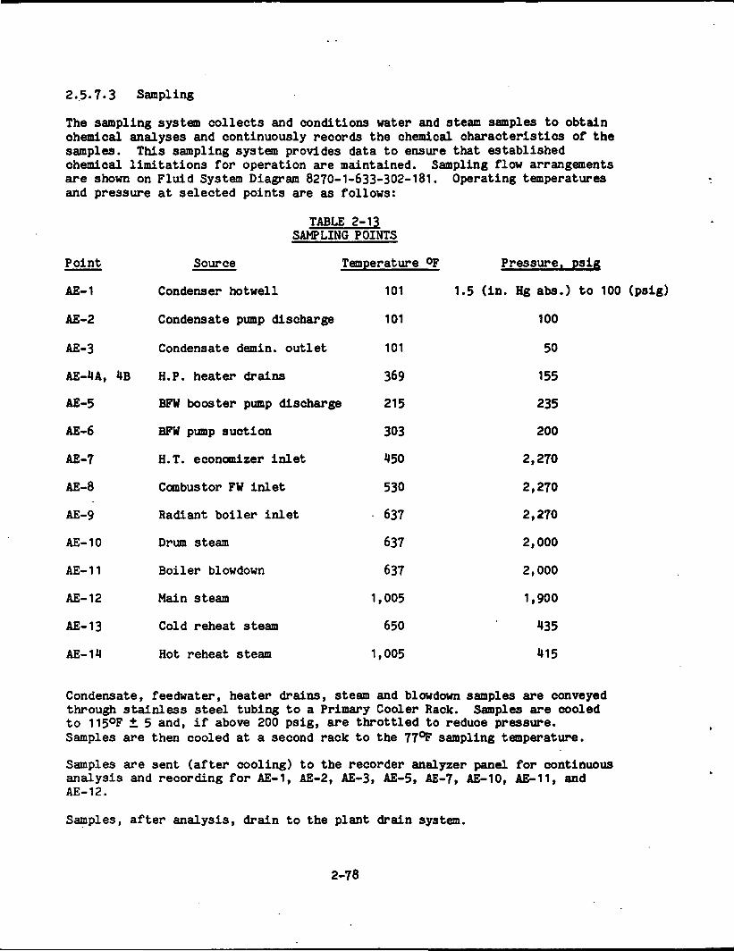
2.5.7-3 Sampling
The sampling system collects and conditions water and steam samples to obtainchemical analyses and continuously records the chemical characteristics of thesamples. This sampling system provides data to ensure that establishedchemical limitations for operation are maintained. Sampling flow arrangementsare shown on Fluid System Diagram 8270-1-633-302-181. Operating temperaturesand pressure at selected points are as follows:
TABLE 2-13Sj)
Point Source
AE-1 Condenser hotwell
AE-2 Condensate pump discharge
AE-3 Condensate demin. outlet
AE-4A, 4B H.P. heater drains
AE-5 BFW booster pump d
AE-6 BFW pump suction
AB-7 H.T. economizer inlet
AE-8 Combustor FW inlet
AE-9 Radiant boiler inlet
AE-10 Drum steam
AE-11 Boiler blowdown
AE-12 Main steam
AE-13 Cold reheat steam
AE-14 Hot reheat steam
Condensate, feedwater, heater drains, steam and blowdown samples are conveyedthrough stainless steel tubing to a Primary Cooler Rack. Samples are cooledto 115°F ± 5 and, if above 200 psig, are throttled to reduce pressure.Samples are then cooled at a second rack to the 77°F sampling temperature.
Samples are sent (after cooling) to the recorder analyzer panel for continuousanalysis and recording for AE-1, AE-2, AE-3, AE-5, AE-7, AE-10, AE-11, andAE-12.
Samples, after analysis, drain to the plant drain system.
2-78
SAMPLING POINTS
Temperature °F
101
icharge 101
mtlet 101
369
.scharge 215
303
et 450
530
st 637
637
637
1,005
650
1,005
Pressure, psig
1.5 (in. Hg aba.) to 100 (psig)
100
50
155
235
200
2,270
2,270
2,270
2,000
2,000
1,900
435
415
2.5.7.4 Industrial Gas Systems
The Industrial Gas System consists of the Plant Service and Instrument AirSupply System as shown on Fluid System Diagram 8270-1-652-302-211 andMiscellaneous Gases as shown on Fluid System Diagram 8270-1-652-302-242.
2.5.7.4.1 Plant Service Air and Instrument Air Supply System
Reciprocating air compressors deliver a minimum of 1,000 scfm clean, dry, oil-free, -44op dewpoint compressed air through a single header system throughoutthe plant for use as either service air or instrument air. A large airreceiver located in proximity of the compressors avoids short cycling of theoperating compressor and minimizes air surges on the dryers. Smaller airreceivers are located throughout the plant to accommodate local high userates. Two air receivers located in the turbine hall and near the MHD powertrain are designated as instrument air receivers to provide storage ofinstrument air for these critical areas.
2.5.7.4.2 Miscellaneous Gases
The Miscellaneous Gases System is a group of four separate subsystems designedto supply industrial type gases for the steam turbine generator, backup supplyfor the MHD magnet system, and inert gas for blanketing various pieces ofequipment throughout the plant. The system consists of the following gases:
1. Helium - provided in bottles for backup to the regular heliumdistribution system.
2. Carbon dioxide - provided in bottles to purge the hydrogen from the acgenerator when it is shut down during outage or for maintenance.
3. Hydrogen - provided in bottles to make up for leakage from the acgenerator cooling system, and as a batch supply to refill the systemafter the generator has been purged.
4. Nitrogen - gaseous nitrogen is received from the air separation unit andis compressed, cooled and stored in tanks. The nitrogen gas is used forblanketing to.eliminate potentially explosive conditions in the coalpreparation and injection system. Nitrogen and is also used to replacewater in steel vessels and piping to reduce possibility of oxygencorrosion when the equipment is out of service.
2.5.7.5 Fuel Oil System
The fuel oil storage system is used for startup, shutdown, hot stand-by,station heating and emergency power generation, and is shown on Fluid SystemDiagram 8270-1-413-302-281.
No. 2 fuel oil is unloaded from rail tank cars into a main oil storage tank;truck unloading is a backup. The main fuel oil storage tank is an aboveground tank, diked, vented and designed to provide a one month supply(840,000 gallons) at plant maximum operating fuel oil consumption rates. Fuel
2-79
oil transfer pumps provide fuel to four underground fuel oil transfer tanks.Each underground storage tank is fitted with external fill connections, vents,level indicators and electric submersible fuel oil pumps that supply fuel oilto the user and recirculation back to the transfer tank. The four transfertanks and users, are:
Heating boiler for coal system control buildingHeating boiler for warehouseAuxiliary boilers/emergency gas turbine generator/diesel fire pump.Vitiated air preheater
2.5.7.6 Plant Industrial Waste
The Plant Industrial Waste System collects, stores, transfers and processes asneeded the liquid and sanitary wastes generated in the facility so thatresulting effluents are in compliance with discharge regulations. TheIndustrial Waste System is shown on Fluid System Diagram 8270-1-641-302-371.
Major sources of industrial waste are:
Coal pile runoff.Chimney wash and air heater wash.Building drains.Wastewater treatment.Fuel oil unloading and storage runoff.Plant yard drainage.Sanitary wastes.
2.5.7.6.1 Coal Pile Runoff (CPR)
Diking and trenching are provided around the coal storage piles to preventsurface runoff from entering the piles and to collect runoff from the pilesfor treatment. Runoff goes to a lined collection basin designed for a10 year, 24 hour per day rainfall. (Rainfall in excess of the design flow mayoverflow the sump directly to the storm sewer). Large coal particles whichsettle in the basin are removed periodically and returned to the coal pile.
2.5.7.6.2 Chimney Wash and Air Heater Wash
Chimney and air heater wash are acidic and contain fine ash particles. Washwater flows to the coal pile runoff basin and is fed at a controlled ratethrough the CPR treatment system.
2.5.7.6.3 Demineralizer Regenerative Waste
The acid and alkaline wastes from makeup and condensate demineralizerregeneration are sent to the batch demineralizer equalization/neutralizationtanks. Combined wastes are agitated and checked for pH. Sulfuric acid orcaustic solutions are added as needed to "rough" neutralize the wastes.Neutralized wastes are conveyed to the waste collection and equalization tankswith other in-plant wastes for additional processing.
2-80
2.5.7.6.4 Building Drains
Water from the coal thaw shed and control building drains and water from thedust suppression system drains to sumps from which it is pumped to the CPRbasin. Wastewater collected from floor drains at other buildings, where thereis no potential for oil contamination, is pumped to the waste collection andequalization tank. Where oil contamination is probable, sumps are baffled to .intercept the oil which is skimmed off manually. The oil is pumped to theoil/water separator in the waste treatment building. Oil is removed to thewaste oil holding tank for reclaiming; wastewater goes to the waste collectionand equalization tank. .
2.5.7.6.5 Wastewater Treatment
The following wastes are directed to the waste collection and equalizationtank: .
Water pretreatment and treatment wastes such as sludge and filterbackwash.
Fly ash loading wastes and runoff such as excess water for dust controlor spills under the silos.
Slag handling wastes overflow and runoff.
2.5.7.6.6 Fuel Oil Unloading and Storage Area Runoff
The fuel oil unloading areas contain track collector pans, drainage pipes, andcurbs for truck loading. Runoff is pumped to an oil/water separator. Skimmedoil from the separator is pumped to an oil reclaim tank.
2.5.7.6.7 Plant Yard Drainage
Rainfall flows through the storm sewer system to the plant yard runoff basin.Drainage will be continuously monitored to prevent accidental discharge ofspilled contaminants. Oil day tanks and transformers are diked or set aboveconcrete pits so that spills of oil can be contained. Any rainfallcontaminated with oil will be processed through the oil/water separator.
2.5.7.6.8 Sanitary Wastes
Sanitary waste is shown on Fluid System Diagram 8270-1-641-302-381. Sanitarywastes from the ETF are conveyed to an aerated surge tank and from theremetered to a sewage treatment plant. Use of the surge tank allows moreregulated flow and a more uniform biological loading. After disinfection andsand filtration, the treated effluent will meet local and Federal standardsfor biochemical oxygen demand, suspended solids and fecal coliform. Wasteactivated sludge is collected in an aerated sludge holding tank and removed bycommercial scavenger service.
The sewage treatment plant is sized to treat an average flow of 8,000 gallonsper day, based on a working and transient population of 130 people. Capacity
2-81
Includes capability for peaks of 105 operating personnel and 250 transient orconstruction personnel at 50 gallons per day per operator, and 7 gallons perday per construction worker or visitor.
2.5.7.7 Fire Service Water
The fire service water system provides the means to detect and combat firesthroughout the facility. Fluids and materials other than water involved inplant fire protection are included generically in this system. The system isshown on Fluid System Diagram 8270-1-781-902-U01.
Water for fire protection is stored in the lower portion of the filtered watertank. Supply is adequate for 2 hours (300,000 gallons) and there are no non-fire service connections below this tank volume. A separate 300,000 gallonstorage tank is available as a reserve. A separate motor driven fire pump isassigned for fire service and a diesel driven fire pump is in reserve. Bothare 100 percent capacity and start automatically when preprogrammed dataindicate a need for them. System water pressure is maintained at 125 psig bya separate jockey pump. Isolation valves are located in the fire water loopsto localize service loss in the event of pipe rupture or equipment outage.Fixed fire suppression equipment includes:
Wet pipe sprinklersDry pipe sprinklerAutomatic water sprayHalon suppressionPreaction sprinklersFixed subsurface foam
Nitrogen inerting is provided for:
Coal bunkersCoal silosCoal feed lock hoppers
Portable fire extinguishers are to be available throughout the facility andselected to combat specific fire hazards.
Fire detection equipment is to be located in the following structures:
Inverter BuildingCompressor BuildingSwitchgear Building
Manual fire alarms are located throughout the plant. They initiate localwarning and remote signals in the main control room.
2-82
2.5.7-8 Domestic Services
2.5.7.8.1 Potable Water
Water for drinking, washing or laundering is drawn from the potable watertank. Tank capacity is 4,000 gallons, and is provided with a 120 gpm makeupcapacity. See Section 2.5.7.2 for description of Plant Makeup Water System.
2.5.7.9 Heating, Ventilating and Air Conditioning
Heating, ventilating and air conditioning services provide:
Protection against freezing of water suppliesElimination of unwanted surface condensationComfortable working environmentsDilution of extraneous odorsControlled environments for instrumentation
Major components utilized include:
Water chillersSteam and electric heatersPackaged oil fired boilersPerimeter hot water baseboard heaters
Crossover steam (from exhaust of intermediate pressure turbine to inlet of lowpressure turbine) backed by auxiliary steam will be used for steam and hotwater heating throughout the plant. Supplementary oil-fired boilers will beavailable at out buildings such as the coal system control building and thewarehouse. Areas needing special conditioning such as the computer room,electrical areas, instrument rooms and control rooms will be provided withduct reheat coils for temperature and humidity control.
TABLE 2-1
Zone
AdministrationBuilding 2,600
Compressor Building 6,050
MHD Building 4,870
Inverter Building 1,653
Consolidation Area 825
MAJOR VENTILATING AND AIR CONDITIONING ZONES
HeatLoad
Btu/hr(1o6)
CoolingLoad
Tons
VentilationCFM(103)
90
401
200
272
269
117
60
50
130
260
100
50
TempLimits
op
78
60 to 104
60 to 104
60 to 104
60 to 104
2-83
PRECED5HG PAGE BLANK MOT F5LMED
2.5.8 Facilities
2.5.8.1 Yard Coal Handling
When in full operation the ETF will utilize 101.8 tons per hour of as-receivedMontana Rosebud sub-bituminous coal. Yard facilities include:
1. Rail Car Unloading
The coal unloading and storage area is 800 feet long and 500 feet wide.Some 3 miles of track around the site provides flexibility for routingand storing cars. Thawing in the 400 foot long sheds consumes power at7 MW per unit train. Coal is dumped into 300 ton capacity hoppers andconveyed to the coal transfer house.
2. Storage Bunkers
Excess or initial storage coal is moved to two 30 day storage piles, each200 feet by 500 feet by 40 feet high. To prevent spontaneous combustionin the pile, the coal should be compacted every 12" to a density of70 Ibs/ft^ ventilated with perforated ducts, and the temperature in thepile monitored.
. Coal being prepared for injection into the combustor is conveyed tostorage bunkers which feed the pulverizing mills.
» »Section 2.5.6.3 describes the coal management equipment and subsystems.
2.5.8.2 Yard Seed Handling
Fresh potassium carbonate seed will arrive by sealed railroad car and beunloaded into the hopper shed. From the shed the seed will be conveyed to two50 foot diameter by 50 feet high silos, each. From the silo the seed moves tothe metering hopper and is sent to the pulverizer at a controlled rate.
Recycle seed (potassium sulfate) recovered from the HR/SR is conveyed tostorage hoppers and transferred to the spent seed silo. Seed from the silo istrucked to the seed storage area, from which reclaimed measured quantities areadmitted to the pulverizer along with fresh seed.
Details of the seed management equipment and subsystems are given inSection 2.5.6.4.
2.5.8.3 MHD Building
The MHD area contains the.major power equipment of the topping cycle;combustor, generator system, magnet and the supporting systems of cryogenics,consolidation circuitry and the magnet power supply. Total area is 196 feetin the lateral (E-W) direction and 168 feet in the direction of gas flow. Thepower train is located centrally in an area 76 feet by 110 feet. Bayelevation is 100 feet and the 150 ton capacity crane has a lateral span of138 feet.
2-85
Stray fields from the magnet impose limitations on location of susceptibleequipment and access for personnel. See SDD-503, Section 5.5 for limits.Within restricted areas personnel working time is limited as defined inSection 3-11 of the DRD.
The magnet assembly is designed to permit uncoupling from the power train andmovement on rails 34 feet (west) during non-operation of the MHD power train.This movement, to a prepared area, will facilitate removal of the channel formaintenance or replacement.
Slag removal tanks are in a Ml foot deep pit beneath the combustor. Pit plandimensions are 42 feet (E-W) by 18 feet. During MHD Power Train operationvoltage potentials at the combustor reach 30,000 V and the collection tanksand the feed lines to the combustor are electrically isolated. Duringoperation access to the power train area will be restricted.
2.5.8.4 Turbine Generator Building
The turbine generator complex, 6 bays wide, (E-W) 168 feet and 3 bays long,84 feet, houses the main turbine generator, main condenser, boiler feed pumpsand drives, feedwater heaters, and auxiliary equipment. Height of the bays is92 feet. A 100 ton crane on an 84 foot span traverses the area.
A condensate pump pit extends 4 feet below ground level. Ample access areaand lay down area is provided, and if necessary heavy pieces can be loaded onflat cars at the railroad bay at the building west end and taken outside fortemporary storage or service.
2.5.8.5 Administration and Service Building
This building is a two-story structure containing personnel facilities such asthe dispensary, cafeteria, lockers, and lavatories. The main machine shop(serviced by a 20 ton crane), instrumentation and electrical repair shops, andthe chemical laboratories are located in this building.
2.5.8.6 Control Complex
The control complex occupies bays extended from the turbine-generatorbuilding. From this area operators communicate with, monitor, and regulateall plant operations and functions. During malfunctions or emergencies, themain control room serves as a shelter from which personnel can assessconditions and act accordingly.
2.5.8.7 Cooling Towers
The cooling tower complex is a mechanical draft tower with 4 cells in each oftwo parallel rectangular units. Plumes and fallout or icing on adjacent areaswill be minimal. The cooling tower and pump house occupy an area 140 by145 feet.
2-86
2.5.8.8 Miscellaneous Buildings and Structures ' '••• . • • " • . . • • " . ' , , - . ! . • •,. --' -*
1. Heat Recovery/Seed Recovery . . . . ; .
The HR/SR structure covers 5 bays, 140 feet (E-W) by M bays, 100 feet andhas 8 elevations for a height of 152.5 'feet. Four platforms areincorporated for access to soot blowers. The slag pit below the radiantboiler is 11 feet deep.
The ESP equipment has its own enclosure and is located adjacent to thewest end of the HR/SR structure.,
2. Air and Oxidant Compressor Building
The compressor installation, adjacent to the west end of the T-G buildingis 5 bays longs, 110 feet, by 3 bays wide, 81 feet. Each of the threeoxidant compressors each have concrete blast walls around them. A 10 toncrane spans the entire length. The design provides individual condensersplaced beneath the two turbine drives of the oxidant compressors and theturbine drive for the Air Separation Unit air compressor. Total buildingheight is 85 feet.
The Air Separation Unit equipment is located on a concrete base, 81 feetby 81 feet, contiguous to the compressor building. The aftercooler,column and adsorption boxes and the reverse exchanger box are the majorinstallations. The column box is 91.5 feet high.
3. Inverter Building
The inverter building is adjacent to the MHD building with an area 168feet wide and 112 feet long. A cooling load of 1 MW is anticipatedduring operation. Four bays at the east end house the switchgearapparatus. The HVAC unit is located in a penthouse at the north end.
1. Fuel Oil Tank, Dike and Pump House
Fuel oil storage and pumping facilities occupy a 130 feet by 130 feetarea located in the north central area of the site. This installation isdesigned in accordance with governmental and industry standards.
5. Main Guard House
The main guard house is located at the main plant entrance and is sizedto accommodate the expected personnel influx to the ETF.
6. Substation (Switchyard and Auxiliaries)
Substation facilities and the filtering and regulating equipment occupyan area 300 feet by 300 feet.
2-87

polleotion and Runoff Ponds
Major pond areas on site include the slag disposal pond in the S-Wquadrant, 210 by 120 feet; coal pile runoff basin, south of the coalpile, that collects drains from the pile gutters, 50 by 180 feet; and astorm water runoff basin, 80 by 190 feet.
2-88
2.6 PLANT OPERATING MODES
2.6.1 Startup
The process of initial startup of a new power plant requires a procedure thatmay extend over months. This follows a checkout phase which may take over ayear. The initial startup establishes that all components and system arefunctioning as specified and that warranties are being met. After the initialstartup phase, subsequent operational startup phases occur on planned orimpromptu schedules and include cold, warm or hot startup. While the threecategories of startup are not firmly defined for the MHD side, they aredefined for the steam side. The basis of definition for the differentcategories of startup is the turbine nozzle chamber temperature, i.e.:
Cold startup; less than 300°FWarm startup; 300°F to 700°FHot startup; over 700°F
The following section describes each of these startup procedures.
2.6.1.1 Initial
Initial startup concurrent with the commissioning of a plant and its beingbrought on stream is the culmination of many months of established checkoutand subsystem preparation. Included In the checkout are:
1. Mechanical Checks:
a. Hydrostatic testing of piping and pressure vessels.
b. Flushing and cleaning of flow paths, installation of temporaryscreens and strainers, final flushing.
c. Inspection and mechanical checks of:
(1) Piping and vessels(2) Valves(3) Pressure relief devicesCO HVAC fans(5) Pumps
2. Electrical Checks:
a. Transformersb. Control circuitsc. Switchgear and bussesd. Power and control cablese. Motor control centersf. Switchboards, control stations, distribution panelsg. Motorsh. Heating elements
2-89
3. Instrumentation and Control Checks:
a. Individual instruments and controls
(1) Test records(2) Installation(3) Cleanliness and absence of defects
b. Static instrument and control circuits:
(1) Response(2) Set point performance(3) Accuracy(*0 Polarity.
Major subsystem preparations prior to initial startup include:
Steam line blowdownWater line flushing and cleanupVerification of battery and standby powerAvailability of plant water suppliesActivation of makeup demineralizersCondensate cleanupFeedwater cleanupTurbine rollBoiler boil outMagnet cool down (about one month)ASU cool down and dryout (3 days)Verification of coal and seed transport and injectionLow load runs
The limiting item in the prestartup sequence is the one month or longer tobring the magnet to its operating temperature of -451.5°F. Upon completion ofthe checkout and preparation effort the initial startup becomes consistentwith cold startup conditions.
2.6.1.2 Operational
1. Cold Startup
For conventional coal fired power plants the elapsed time from combustor(furnace) shutdown to a "cold" plant is about one week. In that time thetemperature of the boiler, turbine, fuel systems, steam lines and watersystems will have reduced to ambient. However, it is assumed that cold watercirculation and treatment have continued, that oxidant plant cooldown andmoisture removal have been accomplished and that the magnet has beenmaintained at operational temperatures (-451.5°F). (If not, cold startup willoccur when those conditions have been attained.)
2-90
Major sequencing for the operational cold startup will be (generically) asfollows:
a. Cold Water Treatment and Cleanup
Water is recirculated through the primary water loop, bypassing thependant type steam superheaters, which are not drainable, and thefeedwater heaters. At the demineralizer entrance, water samples aretaken to determine when cold cleanup is completed. During the cold watercleanup phase, auxiliary steam is used for deaerating and warming thedeaerator. This phase will take 3 hours.
b. Purge of Gas Side
The gas side is purged with air to clear away foreign matter, soot orcarbon residues. The purge duration is determined by gas sampling andlasts approximately ten minutes. The purge can be performed in parallelwith cold water cleanup.
c. Vitiator Firing and Gas Heating
The vitiator is designed to provide 15 percent of rated thermal input orabout 80 MW. Excess air to the vitiator and adequate recycle of exhaustgas and air to the HR/SR afterburner will maintain gas temperatures below1,000°F upstream of the superheater. This temperature limit will bemaintained until steam generation and flow has been attained to preventthermal damage to steam heater tubes. When steam flow is establishedthermal input will be increased and combustor gas temperatures increasedto 2,000°F - + 200°F. This phase will take 6 hours.
d. Hot Water Cleanup
Water temperatures will be increased by gas heating and by use ofauxiliary steam through the deaerator and. deaerator storage tank.
Temperature of the water will be maintained below 550°F until samplesindicate that water quality specifications are being met. This phasewill take 2 hours.
e. Roll and Synchronize Turbine Generator
Thermal input from the vitiator will increase and steam generated willbring up turbine temperatures. Steam bypass to the reheater and use ofauxiliary steam for gland sealing will aid in warmup of turbinecomponents. When turbine temperatures and steam conditions are matched,turbine roll (off the turning gear) will commence. Turbine will bebrought to synchronous speed at a programmed rate.
The generator is synchronized by bringing it on line at the exact matchof turbine speed corresponding to system frequency. Generator voltage isexactly matched to system voltage in phase and level. This sequence willtake 3-1/2 hours.
2-91
f. Phase in Main Combustor
After synchronization, the turbine will be brought quickly to 10 percentload. At this point, with combustor temperatures at 2000OF, coal firingto the main combustor will proceed. During the transition of vitiatorphase out, major activities will include:
(1) Startup and ramp up of ASU compressor.
(2) Startup and ramp up of turbine drive oxidant compressors(Electric motor drive is used until replaced by turbine drive.)
(3) Activate ESP.
(4) Activate coal processing system upstream of pressurized lockhopper.
(5) Activate Slag Management System.
(6) Establish oxidant and coal flow and regulate until 25 percentof full load mass flow.
(7) Stop vitiator firing.
This sequence will take one hour; the first half-hour is inparallel with generator synchronization.
g. Establish Seed Flow and Conductivity
The following sequences are performed:
(1) Seed injection is initiated and adjusted to a levelcommensurate with coal mass flow.
(2) Plasma conductivity is verified,
h. . Load MHD Generator
At stable thermal input the following operations are performed:
(1) Inverter is activated.
(2) Automatic control is initiated.
(3) Magnet is energized and allowed to ramp upwards.
(l») Oxidant oxygen content is increased to 30 percent as generatorloading progresses.
2-92

Loading of the generator will continue under automatic programmedcontrol:
(1) Coordinated increase of oxidant, seed and coal flow rates at1-1/2 percent per minute (corresponding to 2 MW per minuteincrease at turbine generator).
(2) Verification of state points at predetermined load levels.
(3) Transfer to turbine drives and discontinuance of motor drivesas applicable.
i. Stabilize at Base Load
(1) Stabilize at the base load level to attain predeterminedoptimal conditions.
Loading of generator up to base load will take 2-1/2 hours. Total time forcold startup is ten hours. Major activities and times are summarized onFigure 2-7. Temperature profiles of gas and water/steam during cold startupare shown on Figure 2-8.
2. Warm and Hot Startup
A firm definition of warm startup or hot startup as it applies to the MHDsystem has not been developed. However, for the purposes of the ETFconceptual design, it is assumed warm startup would not require cold watertreatment and cleanup and would take slightly more than 7 hours. Hot startupwould eliminate the need for cold and hot water cleanup and to establish steamflow , thereby reducing startup time to approximately 5 hours.
2.6.2 Baseload
The ETF is conceived as a baseload plant with a rating of 200 MWe. At fullload 87 MWe will be generated in the MHD generator and 128 MWe in the turbinegenerator. State conditions and flow parameters for this design point arepresented on the System Heat and Mass Balance, Drawing No. 8270-1-5 0-31 -001.
As a baseload plant, continuous operation is expected for prolonged periods atloads between 75 and 100 percent of rated capacity. Channel stabilityrequires maintaining channel operation as close to full load as practicable,with subsequent high turndown of the steam bottoming cycle. Thus, a split of85 percent of full channel power and 60 percent of full turbine generatorpower is possible, but such turndown ratios are subject to further study.Channel conditions at 75 percent full load flow have been evaluated and acomparison with a coordinated full flow run is presented in Table 2-15.*
•Parameters for the comparative full flow run may differ slightly from currentreference conditions.
2-93

ORIGINAL PAGE BfOF POOR QUALITY
co
V)LLJ
r— OCM UJ
3"— Q_
cs
coLUCJ
OS
I—CO
ta
t— I a«t. ca z o=UJ UJ Z « ^o: ca — uj u*— a: o= _J ^a: £ hZ CJ io
CO
C9
CO
COsCO
co
— ex €•» »••
2-94

3000
FIGURE 2-8 ..... PAGS E§TEMPERATURE LEVELS DURING °!?2nAR QUALITY
COLO START-UP OF POOR QU
4000 -
rGAS
•ATER/STEAM
2000
1000
4 6
TIME HR
8 10
2-95
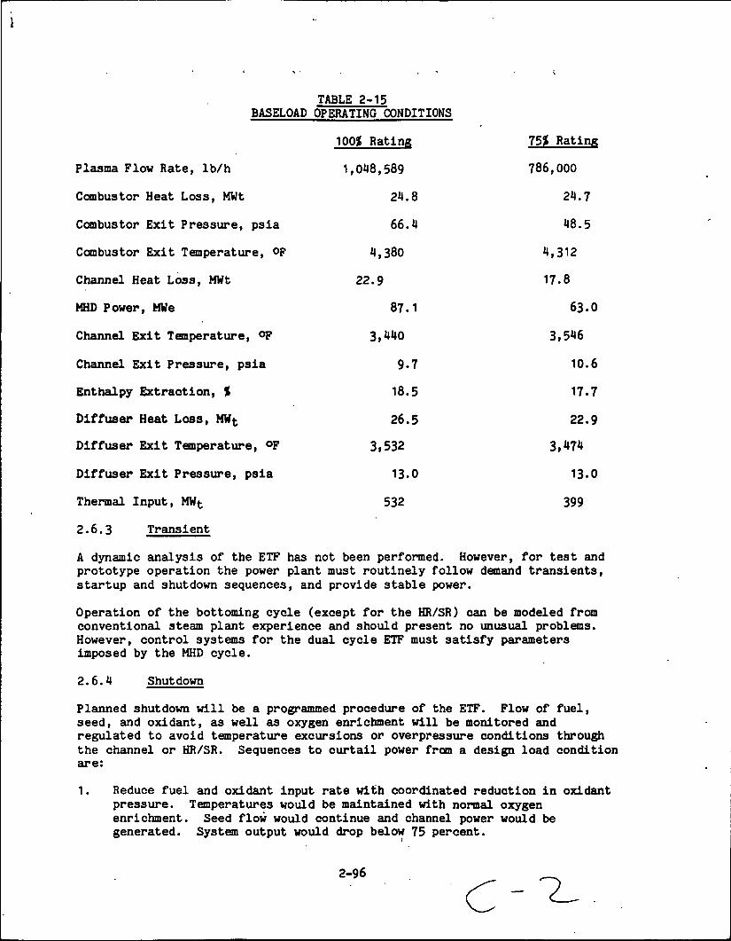
TABLE 2-15BASELOAD OPERATING CONDITIONS
100$ Rating 75* Rating
Plasma Flow Rate, Ib/h 1,048,589 786,000
Combustor Heat Loss, MWt 24.8 24.7
Combustor Exit Pressure, psia 66.4 48.5
Combustor Exit Temperature, op 4,380 4,312
Channel Heat Loss, MWt 22.9 17.8
MHD Power, MWe 87.1 63.0
Channel Exit Temperature, °F 3,440 3,546
Channel Exit Pressure, psia 9.7 10.6
Enthalpy Extraction, % 18.5 17.7
Diffuser Heat Loss, MWt 26.5 22.9
Diffuser Exit Temperature, °F 3,532 3,474
Diffuser Exit Pressure, psia 13.0 13.0
Thermal Input, MWfc 532 399
2.6.3 Transient
A dynamic analysis of the ETF has not been performed. However, for test andprototype operation the power plant must routinely follow demand transients,startup and shutdown sequences, and provide stable power.
Operation of the bottoming cycle (except for the HR/SR) can be modeled fromconventional steam plant experience and should present no unusual problems.However, control systems for the dual cycle ETF must satisfy parametersimposed by the MHD cycle.
2.6.4 Shutdown
Planned shutdown will be a programmed procedure of the ETF. Flow of fuel,seed, and oxidant, as well as oxygen enrichment will be monitored andregulated to avoid temperature excursions or overpressure conditions throughthe channel or HR/SR. Sequences to curtail power from a design load conditionare:
1. Reduce fuel and oxidant input rate with coordinated reduction in oxidantpressure. Temperatures would be maintained with normal oxygenenrichment. Seed flow would continue and channel power would begenerated. System output would drop below 75 percent.
2-96
2. Continue to reduce flows from below the 75 percent design condition to25 percent mass flow at a 1-1/2 percent flow reduction per minute. Whenoxidant pressure reduces to 2 atmospheres, oxygen enrichment will bediscontinued and seed flow rate will be reduced (below the 1 percent massflow point).
3. At the 25 percent mass flow rate and with gas temperatures reduced to the2,200°F level (by addition of excess air) coal flow will be phased outand 'the vitiator phased in.
U. Depending on intent of shutdown, whether for long term (greater than aweek) or short term, power systems will be secured accordingly for thesucceeding startup.
It is expected that power shutdown can be accomplished in 4 hours.
2.6.5 Malfunction Procedures
A failure modes analysis imposes the most severe examination of power systems.Such an analysis requires that the plant be brought to a secure state withinacceptable standards of risk to operating personnel and equipment. Priorsafety analyses, failure modes and effects analyses, and established powerplant procedures eliminate personnel access to areas of danger Procedures forpostulated malfunctions have also been established. Failure modes in the MHDcycle and the responses include:
1. Coal Injection
Oxidant flow and pressure would be reduced. Vitiator firing wouldmaintain a hot standby condition. Multiple injection ports minimizecomplete fuel stoppage.
2. Seed Injection
Sudden stoppage of seed flow could endanger the channel-diffuser andHR/SR and create hazards for personnel. Fuel flow rate and oxidant flowrate and pressure would be reduced. Oxygen flow would be stopped. Thevitiator would replace main combustion for a prolonged outage. Multipleinjection ports minimize complete seed stoppage.
3. Oxidant Injection
Stoppage of oxidant flow would result in corresponding curtailment offuel flow. Damage to the oxidant heater could be severe. Redundantcompressors minimize complete oxidant loss.
For major failure modes such as main pipe rupture, turbine blade failure, keyinstrumentation loss, and meteorological disturbance, the turbine wouldexperience an emergency trip. The plant design includes a 50 percent steambypass. Trip from high load would result in relief and safety valve openingand vent to atmosphere.
2-97
2.7 MAINTENANCE, LOGISTICS, AND SECURITY
2.7.1 Logistics
The ETF requires a programmed supply of fuel, oxidant, compressed air, seed,water, chemicals, lubricants, industrial gases, maintenance, and housekeepingsupplies.
The primary fuel, coal, is the greatest logistical problem. Transportation tothe site is by rail and a 60 day supply of raw coal for full load firing isstored on site to ensure continuity of supply. In an emergency the site canaccommodate supplemental delivery by using plant roads for coal truckdelivery. At full load the plant requires 2,500 tons of raw coal per day.
Seed is delivered to the site in sealed railroad cars to prevent theabsorption of moisture and stored in a moisture isolated environment. A tenday supply of fresh seed is maintained on site. Quantities of seed brought-independs on the seed management techniques employed on site for seed recoveryand recycling. New seed as K2C03 is required at a rate of 100 tons per day.
No. 2 grade fuel oil, used for startup or for emergency operation is normallydelivered to the site by railroad tank cars. Facilities for railcar unloadingare provided. Comparable facilities are also provided for backup delivery andunloading by truck. Fuel oil is used for auxiliary boilers, fire pumpdiesels, and emergency gas turbine generators. The main storage tank, locatedon site, holds a 30 day supply of 840,000 gallons (based on full load of allusers). No. 2 fuel oil should be readily available but equipment designallows for acceptable operation on No. 3 fuel oil.
The compressed air for various requirements is supplied on site by air .compressors. Oxygen, for enrichment of the compressed air, is supplied by anAir Separation Unit (ASU) installed on site. There are no external logisticsinvolved with the oxygen or compressed air.
Water for fire protection and the filtered water system is provided from thePlant Makeup Water system and stored in a 400,000 gallon filtered.waterstorage tank. Plant makeup water, some 4,000 gpm required to meet plantoperating needs, should come from local lake or river sources. Studies on theimpact of groundwater withdrawal will have to be performed. Potable water isexpected to be supplied.from on-site wells. A 300,000 gallon supply of rawwater is provided and stored. With proper treatment it can be used for anyplant purpose.
There are many different chemicals, oils, and greases to be delivered to thesite by railroad and by trucks. Unloading areas and platforms are providedfor receipt of materials. Procedures for handling these materials are wellestablished and considered to be routine.
Industrial gases are brought in by special trucks and/or on tractor-trailersdesigned specifically for this purpose. Each gas has a specific unloadingarea to ensure that the delivered gas is stored in its assigned area.
PRECEDING PAGE BLANK NOT FILMED
2-99

Maintenance needs such as cleaning compounds, cements, gaskets, weldingmaterials, and insulation are brought in by truck. For repair needs, partsare drawn from stock, where a computerized inventory system is maintained, orthe parts are shipped to the site by truck, rail, or courier depending on theequipment size or urgency of need.
2.7.2 Maintenance and Replacement
The MHD-ETF Plant is designed with essentially the same maintenanceconsiderations as a typical base load, coal-fired power plant except thatadditional., specialized features are included for maintenance and/orreplacement of the topping side components. The maintenance concept for thisbase load demonstration plant is based on periodic surveillance of alloperating equipment combined with scheduled maintenance outages forreplacement of relatively short lived items, such as component packings,gaskets and seals.
2.7.2.1 Design Features and Preventative Maintenance
The plant design incorporates various features for minimizing downtimeassociated with scheduled or unscheduled maintenance requirements. Thesefeatures are outlined as follows:
1. Redundant components are provided for the powered equipment in all majorsystems (except for the Oxidant Supply System); e.g., three-50 percentboiler feed pumps, three-50 percent coal drying fans, three-50 percenttransport gas compressors, etc. With this redundancy feature,maintenance can be performed on any given powered component while the ETFplant is operating at full load. In addition, the reliability of plantoperation is significantly increased since the total operating life ofeach powered component is divided among-several redundant units. In theOxidant Supply System, only one ASU air compressor is provided because ofthe inherently high operational reliability of this type of proven aircompressor. Stored liquid oxygen is available for backup supply for alimited period of operation.
2. Laydown and access spaces are provided for repair or replacement of allmajor replaceable components. This includes the special space provisionsfor rolling aside the magnet for access to and replacement of thechannel. For non-replaceable components, such as the radiant boiler,access platforms are provided for accessibility to any componentsubassembly.
3. Computerized and programmed maintenance will be used for all activecomponents. Pertinent performance data including tabulated losses anddeviations from standard are recorded and made available to operators foreasy reference and to identify any problems before they become critical.Work schedules are determined on the basis of equipment design andupdated based on operating data. Maintenance records will be kept up todate.
2-100
i|. Traveling bridge cranes are provided in all the major buildings (with theexception of the HR/SR Building) for handling of the larger plantcomponents. Mobile cranes will be used for equipment for which frequent
• service is not expected.
5. Warehouse and machine shop facilities are provided as part of the overallmaintenance program. A fully equipped machine shop and staff will bemaintained so that some of the plant components can be accepted formachining, welding, or other required repair work. The warehouseprovides storage for a complete computerized inventory of spare parts andrepair materials to minimize system downtime.
6. A complete file of manufacturers' instruction books is available on siteto guide the plant personnel in the maintenance and overhaul of any pieceof equipment. If necessary, a representative of the manufacturer can bepresent to supervise the overhaul or replacement of plant equipment.
7. Preventative maintenance procedures are to be established to satisfyspecific needs of individual components. These include the following:
Specific maintenance operations to be performed.
Maintenance frequencies.
Required system conditions (e.g., normal, shutdown).
Outlines of maintenance procedures.
Definitive restrictions, special tools, and provisioningrequirements.
Preventative maintenance operations, such as inspections, calibrations,routine performance tests, electrical testing, lubrication, replacement,adjustments, and the like are to be performed periodically for thepurpose of maintaining efficient and safe operation of the plant systems.Work schedules will be determined on the basis of equipment design andupdated from actual operating experience.
2.7.2.2 Routine and Operational Maintenance
The following provisions are incorporated in the design and layout of the MHDpower train and adjacent area for routine and operational maintenance.
1. Combustor and Magnet Service Area
A traveling bridge crane is located in the magnet area to assist in thedisassembly, maintenance, and assembly of large components. Laydownspace is provided east of the magnet location. Crane capacity isdetermined by the heaviest piece to be handled after initial assembly. Arail spur is provided into this area.
2-101
2. Channel
Special provisions for removing the channel from the magnet assembly areincorporated into the plant design. These provisions, as shown on LayoutDrawing No. 8270-1-310-010-001, allow for rolling of the magnet away fromthe MHD Power Train and then removal of the channel from the magnetutilizing the channel removal fixture and channel support fixture. Forchannel replacement, the channel support fixture is designed to transportthe old and new channels between the magnet assembly and the railroad carthat is on the spur line in this area. If necessary, the channel can beplaced in the laydown space adjacent to the magnet for repairs.
3. Diffuser/Transition Section
The diffuser/transit!on section can be disassembled and removed by anoverhead crane. Adjacent laydown space is provided, or the sections canbe removed by rail car on the rail spur provided in the area.
U. Radiant Boiler
The radiant boiler will be furnished with access platforms at allelevations required for access to boiler subassemblies. Platforms willallow for "shift" operations, such as visual inspections (observationports, etc.) and soot blower maintenance.
Tube leaks will be handled either from existing platforms or through theuse of temporary scaffolding from which the required repair work will bedone.
5. Recuperative Heat Exchangers
No customized provisions have been incorporated for the superheater,reheater, intermediate temperature oxidant heater, or economizers. Asrequired, sections will be removed for repair. Since the gas side isexpected to be more erosive - corrosive than in conventional service,generous space allotments are being made for soot blowers and accessaisles.
6. ASU and Oxidant Compressors
These compressors are located in the Air and Oxidant Compressor Building.A traveling bridge crane, sized for the heaviest component after initialerection, runs the entire length of the area parallel to shaftcenterlines. The compressor casing is split horizontally and amplelaydown area (and substantial operating redundancy) are provided.
7. Turbine Generator Building
Turbine Generator building maintenance will be conventional. The area isenclosed and is supplied with a bridge crane capable of handling thelargest component after initial erection. Included in the main turbinearea are the turbine driven and motor driven boiler feed pump assemblies.Casings are split horizontally and the machinery can be serviced by the
2-102
area bridge crane. Ample laydown space has been allotted to ensure thatmaintenance of "scheduled" equipment can be performed within acceptabledowntimes for conventional systems.
Auxiliary apparatus, pumps, and heat exchangers are located below the T-Goperating floor level. Aisles for fork lifts, dollies, and fieldassembled "A" frames are provided to facilitate overhaul of these smallerunits.
8. Indoor (Ready) Coal Handling Area
A mobile crane and a monorail system will be utilized to assist inmaintenance of pulverizing mill equipment. Sufficient aisle space willfacilitate crane maneuvering. The pulverizers have relatively highfrequency maintenance requirements. Coal feeders located above thepulverizing mills have adequate clearance for belt changing and routineinspection and servicing.
The bunker loading system is proven equipment. A monorail will be usedto remove conveyor drive gears, head pulleys and motor drives for repairor replacement.
2.7.2.3 Shutdown Maintenance Schedules
Equipment shutdown schedules will be determined from the design andconstruction records of equipment by analyzing the operating conditions to beexpected. In particular, the high temperature MHD equipment will be reviewedfor slagging, deposits, and damage. Schedules will be modified based onoperating experience. •
2.7-3 Security
Power plant owners, the licensing agencies and the operating and supervisingpersonnel have recognized and established the need for rigorous plantsecurity. Of major concern are the huge capital costs of equipment, theburdensome expenses of plant downtime, safety of plant personnel andobligations to plant customers and the public at large. In recent years,power plants have become targets of special interest activist groups. Plantsecurity personnel must be trained and have the capability to react to theextremes of terrorist action, as well as impromptu trespassing, authorizedadmission of plant employees, and supervised admission of the public.
2.7.3.1 Personnel Access
Authorized access to the plant is controlled through guardhouses located atthe inner security fence. The main guardhouse is a structure of approximately2,400 square feet adjacent to the service building. Plant personnel will beadmitted by badge identification. Visitors will be admitted afteridentification and verification of proper authorization for entry. Equipmentis available for inspection of packages and vehicles as required. Allvisitors will be badged and permanent registration records kept. Escorts willbe provided as applicable.
2-103
Guardhouses have backup facilities to prevent unauthorized access. Directline communication with the main control room, plant supervision, patrollingguards and local government law enforcement agencies are provided. The siteis enclosed by an outer security fence which defines the property area. Aninner security fence encircles the plant area where active means are employedto prevent unauthorized intrusion. Vehicular access is controlled at theouter fence. Only individually authorized vehicular traffic will be allowedinto plant areas.
2.7.3.2 Internal Secure Areas
Vital internal areas are defined as those where deliberate or involuntarydamage to equipment could result in major disruption of plant services andendangering area personnel. Vital internal areas include the main controlroom, the ETF power train and other elements of the power and supply systems.Admission to these areas is by closely supervised key card access. A specialcase of controlled access during power plant operation, is to the magnet area.Because of the intense magnetic fields generated, restriction zones for timedaccess, depending on the local field value, are monitored to ensure againstviolations. (See Section 2.5.3 for details of magnet restriction zones.)
2-101
2.8 DRAWINGS
2.8.1 Heat and Mass Balance Diagram
The System Heat and Mass Balance, Drawing No. 8270-1-540-314-001 is includedas Appendix 2A.
2.8.2 GAI Drawing List
The current GAI Drawing List is attached as Appendix 2B. Copies of thesedrawings are included in the CDER in the following locations, in accordancewith their functions.
1. The System Heat and Mass Balance is included in Appendix 2A.
2. Fluid System Diagrams and associated drawings are included in theirrespective system design descriptions, following Section 5.5.
3. The balance of the drawings listed in the GAI Drawing List (Appendix 2B)provide information which is relevant to the project conceptual designdescription, and present overall engineering information, but are notincluded with a specific system. Fpr convenience, these drawings arelisted and copies included in Appendix 2C, "Related Drawings."
2-105

APPENDIX 2A
HEAT AND MASS BALANCE DIAGRAM
Dwg. No. 8270-1-540-314-001, Rev. 1 System Heat and Mass Balance
PRECEDING PAGE BLANK NOT FILMED
2-107
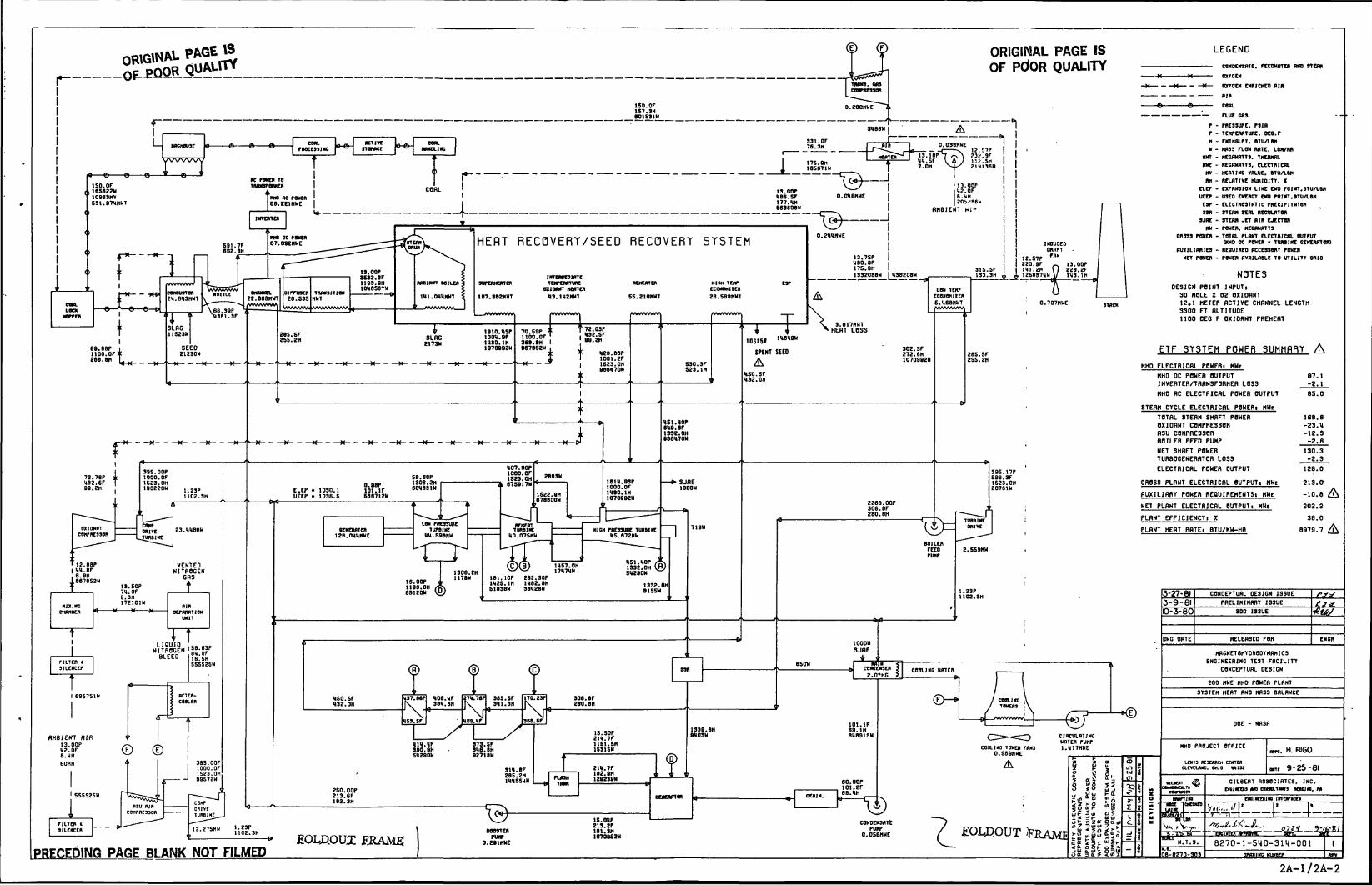
ORIGINAL PAGE ISOF PdOR QUALITY caracranc. rcrauncn (am nm
mtctnonce* cwiicnco nin
HERT RECOVERY/SEED RECOVERY SYSTEM WHO oc POUCH • Tuiamc GCKciunorn- itcauinco ACCESSORY POUCH
MCT paucn - POUCH RVRILRBLC TO UTILITY CRIOI2.7SPuaa.ar17S.8H139208BU
IZ.57Pita.ar ._ 13.OOPI1I.2K (/ 828.U5887HUV 1H3.1H13.00P
SSS2.3F1193.9HtOUOS6-U
unEmcoiincTOrEMTUIC
aionn mnenH3.1H2KWT
•unrxtta
107.88JKUTDESIGN POINT INPUT,
30 HOLE Z QS OXIORMT12.1 METER flCTIVE CHBMNEL LENGTH3300 FT ALTITUDE1100 DEC F eXIORNT PREHERT
3.817HUTHERT LOSS70.S9P t
1tOO.OF2E8.8H I887RS2U , ETF SYSTEM POWER SUMMflRT302.SF
272.EH1070882U
H28.83P1001.2F1523.OH888H70N MHO ELECTBlCflL PBHEBl MHt
HHO DC POWER OUTPUTINVERTER/TRRNSFORHER LOSS
HMD RC ELECTRICRL POWER OUTPUT
STERM CYCLE ELECTR1CHL PBHERl MHf
TOTRL STERN SHflFT POWEROX10RNT COMPRESSORHSU COMPRESSORBOILER FEED PUMP
NET SHflFT POWERTURBOGENERRTOR LOSS
ELECTRICRL POWER OUTPUTH07.39P1000. OF1S23.0H87S917U
395.OOP1000.OF1S23.0H1B0220U
SB.80P1308.2H80V831H
181U.83P1000.0F1U80.1H1070882U
GROSS PLRNT ELECTRICRL OUTPUTi MWc0.88P101.IFS38712H RUXlLIflRT POWER REQUIflEMENTSl MHt
NET PLRNT ELECTRICflL OUTPUTi MHt2269. OOP306.8F280.8H
PLflNT EFFlCIENCTi
PLHNT HERT RRTEl BTU/KM-HRLOU PM93UM
TUKBIKfIM.598HU
HICK PK33UHt TWBIUS.672HU
12.88PI W.SF. 8.an
18878S2H
VENTEDNITROGEN
CHS 181.10P 282.30P112S.1H 1U82.8HS183BN 38U28U
16.OOP1188.8H88120U CflNCEPTUAL DESIGN ISSUE
PRELIHINRRT ISSUE
LIQUIDNITROGEN
BLEED M)SNET8HTOnBDTNRHIC3ENGINEERING TE3T FACILITY
CflNCEPTURL DESIGN
200 HWE HHO POWER PLRNT
3T3TEH HERT RNO HR33 BRLRNCE
101.IF88.1H818915HIS.SOP
2U.7F1151.SH1S3ISH
RMBIENT flIR13.OOPU2.0F8.UH60RH
HHO PROJECT OFFICEcom.;ire TOUCH ruin0.889HUE
395.OOP1000.OF1523.On99572U
2U.7F18J.8H128238W GILBERT R330CIRTE3. INC.
ontmoa HMD cngnLTwna auaim. m250. OOP213.6F182.3H
CONDEK3RTEPUHP
0.056MWEEOUDJQUJ: ERAME 8270-1-540-3114-001PRECEDING PAGE BLANK NOT FILMED
2A-1/2A-2
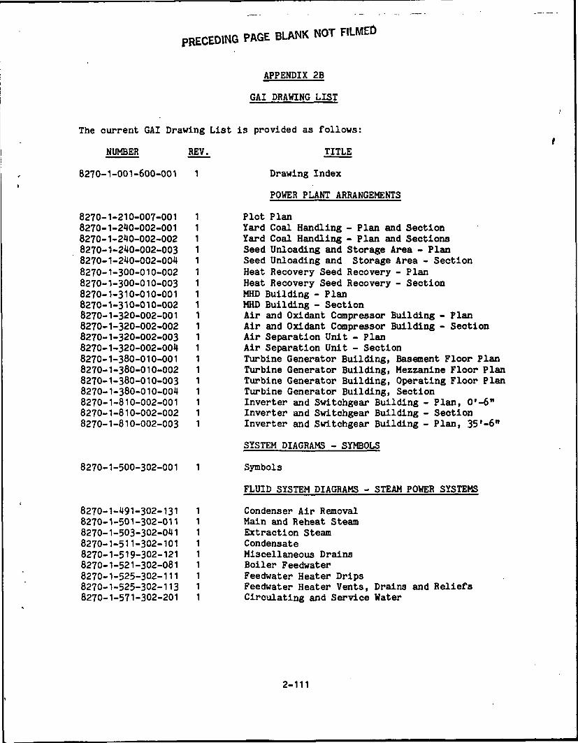
PRECEDING PAGE BLANK NOT FILMED
APPENDIX 2B
GAI DRAWING LIST
The current GAI Drawing List is provided as follows:
NUMBER REV. TITLE
8270-1-001-600-001 1 Drawing Index
POWER PLANT ARRANGEMENTS
8270-1-210-007-001 18270-1-210-002-001 18270-1-210-002-002 18270-1-210-002-003 18270-1-210-002-004 18270-1-300-010-002 18270-1-300-010-003 18270-1-310-010-001 18270-1-310-010-002 18270-1-320-002-001 18270-1-320-002-002 18270-1-320-002-003 18270-1-320-002-004 18270-1-380-010-001 18270-1-380-010-002 18270-1-380-010-003 18270-1-380-010-004 18270-1-810-002-001 18270-1-810-002-002 18270-1-810-002-003 1
8270-1-500-302-001 1
8270-1-191-302-1318270-1-501-302-0118270-1-503-302-0118270-1-511-302-1018270-1-519-302-1218270-1-521-302-0818270-1-525-302-1118270-1-525-302-1138270-1-571-302-201
111111111
Plot PlanYard Coal Handling - Plan and SectionYard Coal Handling - Plan and SectionsSeed Unloading and Storage Area - PlanSeed Unloading and Storage Area - SectionHeat Recovery Seed Recovery - PlanHeat Recovery Seed Recovery - SectionMHD Building - PlanMHD Building - SectionAir and Oxidant Compressor Building - PlanAir and Oxidant Compressor Building - SectionAir Separation Unit - PlanAir Separation Unit - SectionTurbine Generator Building, Basement Floor PlanTurbine Generator Building, Mezzanine Floor PlanTurbine Generator Building, Operating Floor PlanTurbine Generator Building, SectionInverter and Switchgear Building - Plan, Q'-6"Inverter and Switchgear Building - SectionInverter and Switchgear Building - Plan, 35'-611
SYSTEM DIAGRAMS - SYMBOLS
Symbols
FLUID SYSTEM DIAGRAMS - STEAM POWER SYSTEMS
Condenser Air RemovalMain and Reheat SteamExtraction SteamCondensateMiscellaneous DrainsBoiler FeedwaterFeedwater Heater DripsFeedwater Heater Vents, Drains and ReliefsCirculating and Service Water
2-111
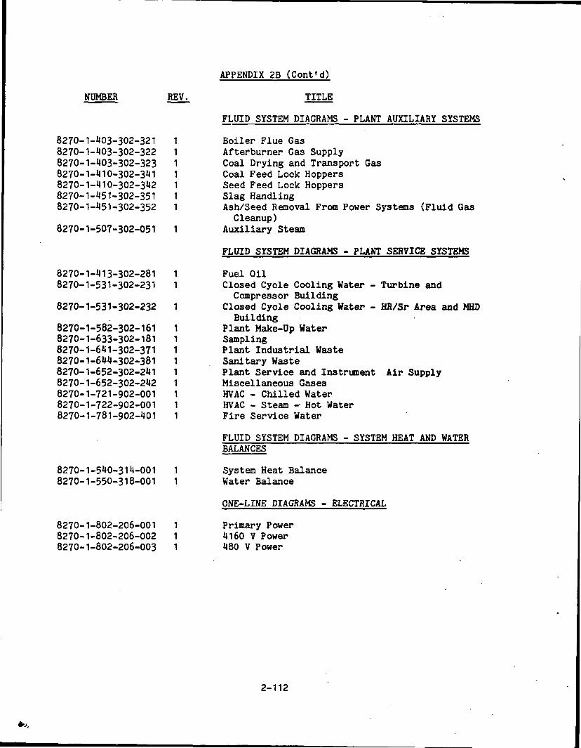
APPENDIX 2B (Cont'd)
NUMBER REV. TITLE
FLUID SYSTEM DIAGRAMS - PLANT AUXILIARY SYSTEMS
8270-1-403-302-321 1 Boiler Flue Gas8270-1-403-302-322 1 Afterburner Gas Supply8270-1-403-302-323 1 Coal Drying and Transport Gas8270-1-410-302-341 1 Coal Feed Lock Hoppers8270-1-410-302-342 1 Seed Feed Lock Hoppers8270-1-451-302-351 1 Slag Handling8270-1-451-302-352 1 Ash/Seed Removal From Power Systems (Fluid Gas
Cleanup)8270-1-507-302-051 1 Auxiliary Steam
FLUID SYSTEM DIAGRAMS - PLANT SERVICE SYSTEMS
8270-1-413-302-281 1 Fuel Oil8270-1-531-302-231 1 Closed Cycle Cooling Water - Turbine and
Compressor Building8270-1-531-302-232 1 Closed Cycle Cooling Water - HR/Sr Area and MHD
Building8270-1-582-302-161 1 Plant Make-Up Water8270-1-633-302-181 1 Sampling8270-1-641-302-371 1 Plant Industrial Waste8270-1-644-302-381 1 Sanitary Waste8270-1-652-302-241 1 Plant Service and Instrument Air Supply8270-1-652-302-242 1 Miscellaneous Gases8270-1-721-902-001 1 HVAC - Chilled Water8270-1-722-902-001 1 HVAC - Steam -- Hot Water8270-1-781-902-401 1 Fire Service Water
FLUID SYSTEM DIAGRAMS - SYSTEM HEAT AND WATERBALANCES
8270-1-540-314-001 1 System Heat Balance8270-1-550-318-001 1 Water Balance
ONE-LINE DIAGRAMS - ELECTRICAL
8270-1-802-206-001 1 Primary Power8270-1-802-206-002 1 4160 V Power8270-1-802-206-003 1 480 V Power
2-112

APPENDIX 2C
RELATED DRAWINGS
The following drawings, listed in Appendix 2B, provide information which isrelevant to the project conceptual design description since they are not includedwith a specific system, they are provided in this Appendix:
NUMBER REV.
8270-1-001-600-001 18270-1-210-007-001 18270-1-300-010-002 18270-1-300-010-003 18270-1-310-010-001 18270-1-310-010-002 18270-1-320-002-001 18270-1-320-002-002 18270-1-320-002-003 18270-1-320-002-001* 18270-1-380-010-001 18270-1-380-010-002 18270-1-380-010-003 18270-1-380-010-001 18270-1-810-002-001 18270-1-810-002-002 18270-1-810-002-003 18270-1-500-302-001 18270-1-550-318-001 1
TITLE
Drawing IndexPlot PlanHeat Recovery Seed Recovery - PlanHeat Recovery Seed Recovery - SectionMHD Building - PlanMHD Building - SectionAir and Oxidant Compressor Building - PlanAir and Oxidant Compressor Building - SectionAir Separation Unit - PlanAir Separation Unit - SectionTurbine Generator Building, Basement Floor PlanTurbine Generator Building, Mezzanine Floor PlanTurbine Generator Building, Operating Floor PlanTurbine Generator Building, SectionInverter and Switchgear Building - Plan, 0'-6n
Inverter and Switchgear Building - SectionInverter and Switchgear Building - Plan, 35'-6"Symbols (Fluid System & Electrical Deiagrams)Water Balance
2-113

A
B
C
D
E
F
G
H
10 9 8 7 6 | 5 4 3 2 1
ORIGINAL PAGE Si OftitiffiMAL fliOF POOR QUALITY. OF PQQR QUALITY
DRAWING NO. DESCRIPTION DRAWING NO. DESCRIPTION DRAWING NO. DESCRIPTION
B270-1 -001 -600-001 DRAWING INDEX SYSTEM DIAGRAMS - SYMBOLS FLUID SYSTEM DIAGRAMS-PLANT SERVICE SYSTEMS
82 JO-I -500-302-001 SYMBOLS 8270-1 -41 3-302-281 FUEL OIL (SOD-281 )POWER PUNT ARRANGEMENTS
8270-1-531-302-231 CLOSED CYCLE COOLING WATER - TURBINE (NO COMPRESSOR BUILDING (SDD-231)
8270-1-210-007-001 PLOT PLAN FLUID SYSTEM DIAGRAMS-STEAM POWER SYSTEMS 8270-1-531-302-232 CLOSED CYCLE COOLING UTER - H.:/SR AREA AND KHD BUI LOING (SDD-231 )
8270-1-240-002-001 YARD COAL HANDLING - PLAN Al
8270-1-240-007-002 YARD COAL HANDLING - PLAN A
8270-1-240-002-003 SEED UNLOADING AND STORAGE
8270-1-240-002-004 SEED UNLOADING AND STORAGE
8270-1-300-010-002 HEAT RECOVERY SEED RECOVcRY
8270-1-300-010-003 HEAT RECOVERY SEED RECOVERY
8270-1-310-010-001 MHO BUILDING - PLAN
8270-1-310-010-002 MHD BUILDING - SECTION
8270-1 J20-002 -001 AIR AND OXIOANT COMPRESSOR
8270-1-320-002-002 AIR AND OXIOANT COMPRESSOR
8270-1-320-002-003 AIR SEPARATION UNIT - PLAN
8270-1-320-002-004 AIR SEPARATION UNIT - SECTI
8270-1-380-010-001 TURBINE GENERATOR BUILDING,
8270-1-380-010-002 TURBINE GENERATOR BUILDING,
8270-1-380-010-003 TURBINE GENERATOR BUILDING,
8270-1-380-010-004 TURBINE GENERATOR BUILDING.
8270-1-810-002-001 INVERTER AND SIITCHGEAR BUI
8270-1-810-002-002 INVERTER AND SIITCHGEAR BUI
8270-1-810-002-003 INVERTER AND SWITCHGEAR BUI
FOLDOUI ERAME
* OAI TO07-O
8270-1 -582- 302-161 PLANT MAKE-UP WATER (SOD-IEM40 SECTION (SDD-341) 8270-1-491-302-131 CONDENSER AIR REMOVAL (SOD-131 )
ID SECTIONS (SDD-341) 8270-1-633-302-18, SAMPLING (SDD-,8, )
IREA - PLAN (SDD-342) 8270-1-601-302-011 MAIN AND REHEAT STEAM (SDD-011)
IREA - SECTION (SDD-342) 8270-1-641-302-371 PLANT INDUSTRIAL WASTE (SDO-371)
8270-1-503-302-041 EXTRACTION STEAK (SOO-041 )
8270-1-644-302-381 SANITARY IASTE (SDD-371)
. PLAN 8270-1-504-302-031 STEAM BY-PASS AND START-UP (SDD-031 )
- SECTION 8270-1-652-302-241 PLANT SERVICE AND INSTRUMENT AIR SUPPLY (SOO-241)
8270-I-5II-302-10I CONDENSATE (SOD-101 ) 8270-1-652-302-242 MISCELLANEOUS GASES (SOO-241 )
8270-1-519-302-121 MISCELLANEOUS DRAINS (SDD-1 13) 8270-1-721-902-001 HVAC - CHILLED MTER (SOD-701 )
8270-1-521-302-081 BOILER FEEDWATER (SDD-081 ) 8270-1-722-902-001 HVAC - STEAM - HOT IATER (SDD-701 )
BUILDING - PLAN 8270-1-525-302-111 FEEDWATER HEATER DRIPS (SOD-11 1 ) 8270-1-781-902-401 FIRE SERVICE WATER (SDD-401)
BUILDING - SECTION [
8270-1-525-302-113 FEEDWATER HEATER VENT?, DRAINS AND RELIEFS (SDD-113) ^>
8270-,-57,-302-20, C.RCULATING AND SERVICE WATER (SDD-201) FLUID SYSTEM O.AGRAMS-SYSTEM HEAT AND WATER BALANCES V HOLDOUT F.RAMEJ
SHZZE'F^ORTLA'N 8270-1-540-3,4-00,OPERATING FLOOR PLAN FJ.UID SYSTEM DIAGRAMS - PLANT AUXIL IARY SYSTEMS B270-1 -550-31 8-001 WATER BALANCE ;SECTION" '
8270-1-403-302-321 BOILER FLUE GAS (SDD-321)LDING - PLAN, o'-6" 8270-1-403-302-322 AFTERBURNER GAS SUPPLY (SDD-321)LDING - SECTION 8270-1-403-302-323 COAL DRYING AND TRANSPORT GAS (SDD-321 )DING - PI MI 351-8" ' ..!•"• "°- c-373-°53
»7n-i-.in.,M_«, r... »Fn,nr.unpK^(Wn.^ l) ONE LINE DIAGRAMS - ELECTRICAL . 3WJI CONCEPTUAL DESIGN ,SSUE /"
8270 I-410 302 342 SEED FEED LOCK HOPPERS (SDD 342) 3-17-81 PRELIMINARY ISSUE T r-"
8270 1-802 206 001 PRIMARY POWER (SDD 001)
82IO-l-4!>l-302-3b2 ASH/SbbU KbMUVAL (-HUM PUWbK SYSIbMS 8270-1-802-206-003 480V POWER (SDO-801) '««,"" ' nc, c..cn coo euro
8270-1-607-302-051 A U X I L I A R Y STEAM (SDD-051 ) HAGNETOHYOROOrNAMICSENGINEERING TEST FACILITY
CONCEPTUAL DESIGN
DRAWING IND1X
300 MWc
OOE - NASA
AMHO PROJECT OFFICE .„„. H R|G0
l»ll I»[»CH CEITII
0- -r- • IUHUW.MIO «i» M«y-^5-8 l
TuiO* ? "° £.«»- |A^> GILBERT ASSOCIATES, INC.
aOZZO) N < X OHAFTIHO KNOIHCtHINaiNTKMrACa
•^ ^^~ _ O O MADE CHECKED 1. |. 1 t. »•
go-S^ \ \ E GA./-i „]alSp5~e - — «™ j ^ / ~:£|iz - 5 - -^-^- . ^i^-------^---^;----.S^8^ ^ °- """ "°"E 8270-1-001-600-001 1§^^)S - S '"08B270-20I o-.w^G HU..CR KtV
A I I I I I I I I I I I 1 I I I I I I I • 1 1 1 III o r_ i / 7 r_91
A
B
C
D
E
F
G
H
4
»•

10
ORIGV
ORIGINAL P M BOF
OF,
fAGE ?SQUAUt*
fi~<&
B2POON I.;
/^ 1 1 -/ s.-'L . Jj..-'
0=5=^
/ •?>*.+. «.4i,1
~-V£
•*••*&
J
-it-/
•• 4:rS, -j:'
A*-AJ.-'34 TV" ••!«
Xi
"T*
- 8 . '
:fr?Ti'. ,-uliu
SCALE IN FEET TO MID LINE
L500 N
I.ODOJJ
47
H
NOTES:
1. RAILROAD TRACKS SHOIN INDICATES THAT QUANTITY REQUIRED TOHANDLE 100 RANOOI SIZEO CARf, ENGINE RUN AROUND?. EIPTYCAR STORAGE, ETC. ARRANGEIENT SHOIN INDICATES FOOTAGENEEDED ONLY. ACTUAL TRACK LAYOUTS CAN BE ADJUSTED TO SUITCONDITIONS.
2. LOCATION FOR SITE HAS NOT BEEN DETERIINEF.• SEE ENLARGED PLAN AND SECTION
^ . 1
fi—„—:._";: .
B.10.11.12.13.14.15.IB.17.18.18.20.21.22.23.24.25.26.27.28.29.3H.31.32.33.34.35.36.37.36.39.40.41.42.43.44.45.46.47.48.49.
L E G E N D
INTAKE STRUCTURE ,ROTARY CAR DUMPERCAR THAWING SHEDCOAL SYSTEM CONTROL BUILDINGSTORMIATER RUNOFF BASINOIL/IATER SEPARATORFUEL OIL TANC. DIKE AND PUMP HOUSE30 DAYS COAL PI IE STORAGE (EACH)•AREHOUSELIQUID OXYGEN TANKSMAIN GUARD HOUSESTORAGE TANKS-FILTERED. FIRE SERVICE. RAI IATER AND CONOENSATECOOLING TOWERSADMINISTRATION, SERVICE AND MACHINE SHOPAIR SEPARATION UNITCOAL PILE RUNOFF BASINYARD COAL CRUSHER HOUSESANITARY. INDUSTRIAL WASTE SLUDGE TREATMENT BUILDINGSPENT SEED AND FLY ASH SILOSAFTERBURNER GAS FANSAIR HEATERFLUE GAS RECYCLE FANSAIR AND OXIDANT COMPRESSOR BUILDINGAUXILIARY BOILER BUILDING 'QO 0 IWATER TREATMENT AND DEMORALIZATION BLDG.TURBINE - GENERATOR BUILDING SCALE IN FEETCONTROL COMPLEXTRANSFORMERSSWITCHYARD I.D. NO. C-073-016SWITCHGEAR BUILDINGINVERTER BUILDINGMISCELLANEOUS GAS STORAGE BUILDINGHEAT AND SEED RECOVERY BUILDINGMHD BUILDINGSEED FEED BUILDINGCOAL FEED BUILDINGSEED UNLOADING FACILITYBAGHOUSECOAL PREPARATION BUILDINGCOAL DRYING FANSELECTROSTATIC PRECIPITATORLOW TEMPERATURE ECONOMIZERTRANSPORT GAS COMPRESSORSCHIMNEY
SETTLING 1 SURGE TANKSDEWATERING BIN?1.0. FANSSLAG DISPOSAL PONDHARMONIC FILTERINGPOWER FACTOR CORRECTION
FOLDOUI FRAME
o
°0
eraX a
3v7-8l2-13-81
ffft
CONCEPTUAL DESIGN ISSUE
PRELIMINARY ISSUE
RELEASED FOR ENCR.
MAQETOHYORODYNAMICSENGINEERING TEST FACILITY
CONCEPTUAL DESIGN
PLOT PLAN
200 MWe
DOE - NASA
MHD PROJECT OFFICE
in 11 KIUIU cumcunum. oio HIM
U *s".•&-£,
HED
H. RIGO
9-25-81
GILBERT ASSOCIATES, INC.EMOMEEH AW CONSUITANT* KEAOMO. PA
KMalKCKKINO INTCKTACtS
H
8270-1-210-007-001 ' ID B A W I M Q M U H B g R
11 2C-3/2C-4
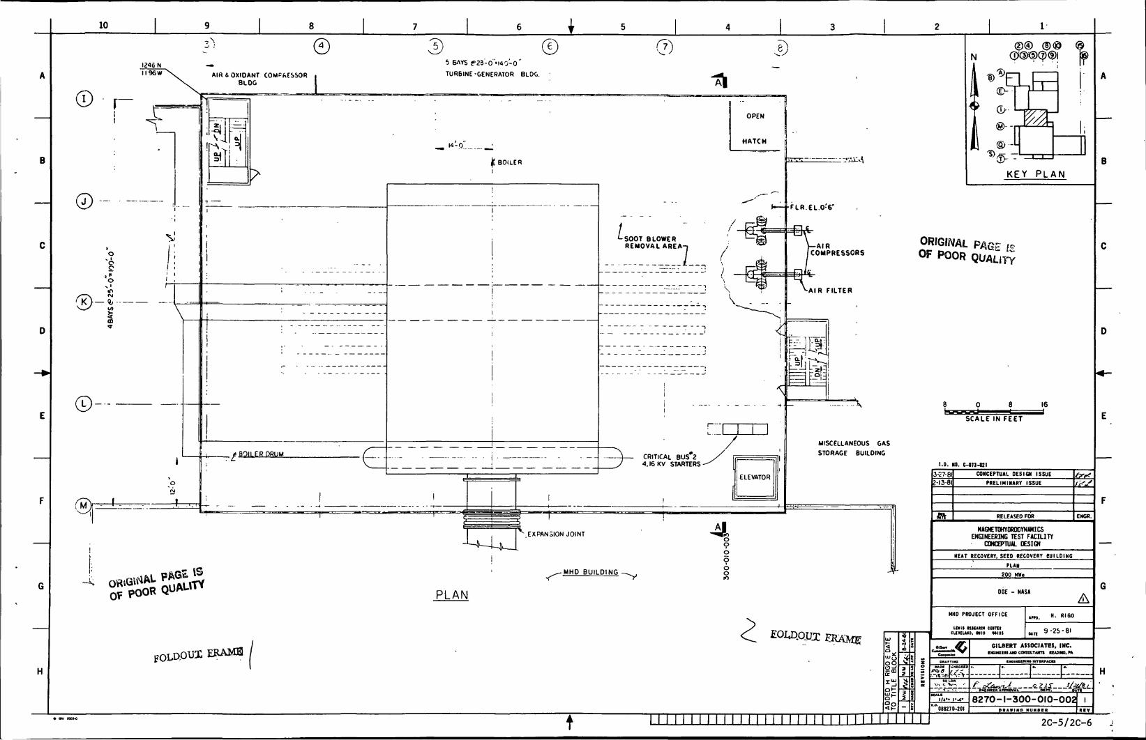
10
I246NI I96W
r
O
"8
L}- -
Oid
®
of
® 5} ©
i
AIR & OXIDANT COMPRESSORBLOC
5 BAYS ff23-o"tl«0-0"
TURBINE -GENERATOR BLDG.
__ 14-0. _;
BOILER
* BOILER DRUM.£.
EXPANSION JOINT
SOOT BLOWERREMOVAL AREA-i
CRITICAL BUS 24.I6KV STARTERS
MISCELLANEOUS GASSTORAGE BUILDING
-MHO BUILDING
PLAN
KEY PLAN
ORIGINAL PAGE f*Of POOR QUALITY
0 8 16i*;
SCALE IN FEET
1.0. NO. C-073-821
Z-I3-8I
S3
3-27-81 CONCEPTUAL DESIGN ISSUE
PRELIMINARY ISSUE
RELEASED FOR
MAQCTOHYOROOYNiMICSENGINEERING TEST FACILITY
CONCEPTUAL DESIGN
EMCR.
HEAT RECOVERY, SEED RECOVERY BUILDING
PLAN
200 HW«
DOE - NASA
MHD PROJECT OFFICE
LEVIS tUEAlU CIITIICLXVELUO. MIO MISS
HAM CMCCKCO'0,8-i*-fi
086270-201
un. "• R'so
9 -25 - 81
GILBERT ASSOCIATES, INC.CNOMURS AW COMULTAKTS RCADMB, M
8270-1-300-OIO-OOZ IP R A W I M O MUMBCR
t2C-5/2C-6
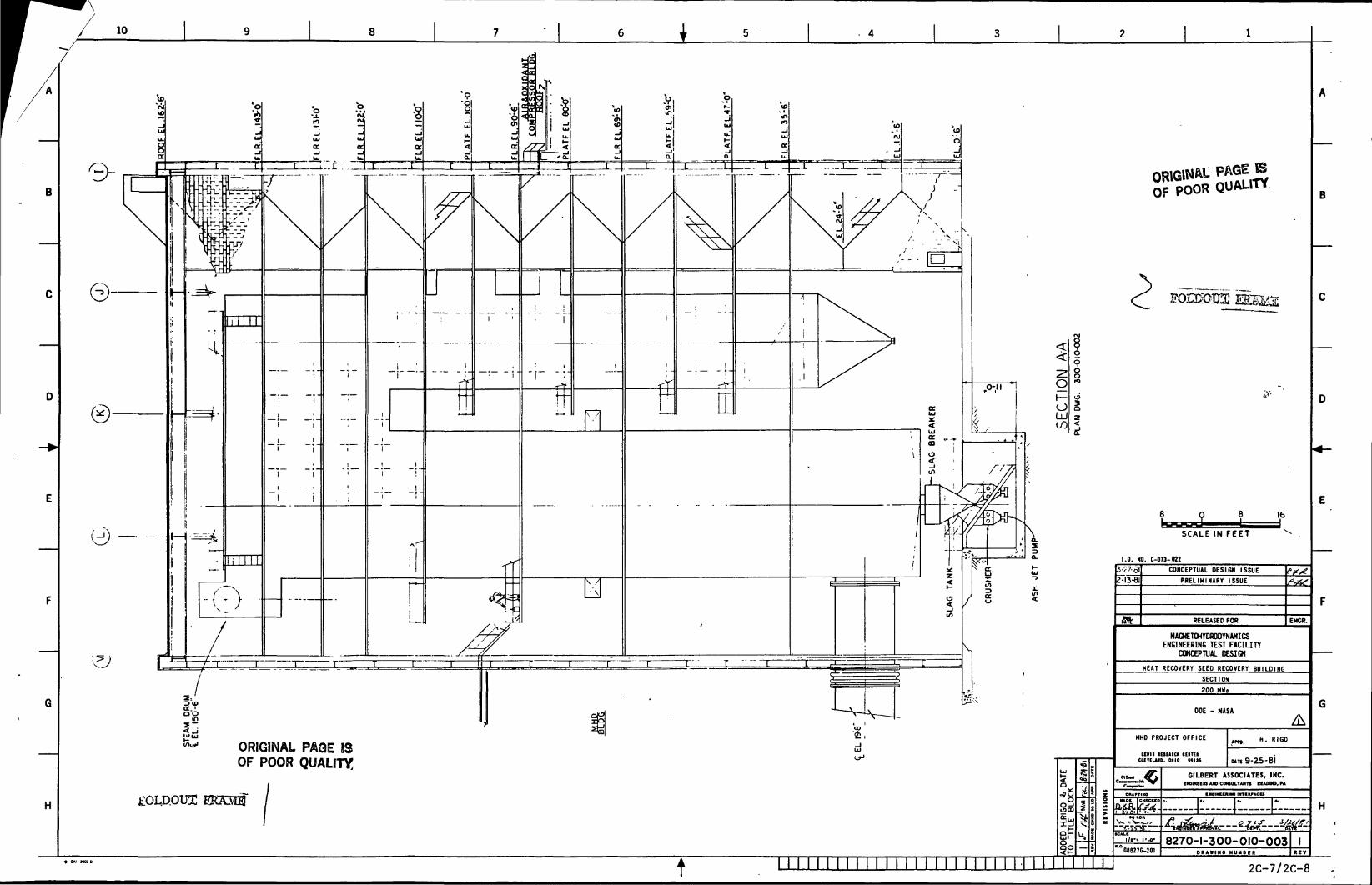
10
H
i
ORIGINAL PAGE ISOF POOR QUALITY:
EOI.D.OUX
oI—oQJto
1§5
OF POOR
1.0. NO. C-073-822
i-27-plZ-I3-6I
CONCEPTUAL DESIGN ISSUE
PRELIMINARY ISSUE
RELEASED FOR ENCR.
MAGNETOHYDRODYNAMICSENGINEERING TEST FACILITY
CONCEPTUAL DESIGN
HEAT RECOVERY SEED RECOVERY BUILDING
SECTION
200 MWg
DOE - NASA
MHD PROJECT OFFICE
LEWIS IESEAICN CEMTEICIEVELARD. OHIO 44116
•4 UK
-~JF"ICALK
I/I'.
088270-201
Am. h. RIGO
TE 9-25-81
GILBERT ASSOCIATES, IHC.AW cowuLTAim RCADMO. M
8270-1-300-010-003OAWIMO MUM8ER
isTr~r
H
t11 2C-7/2C-8
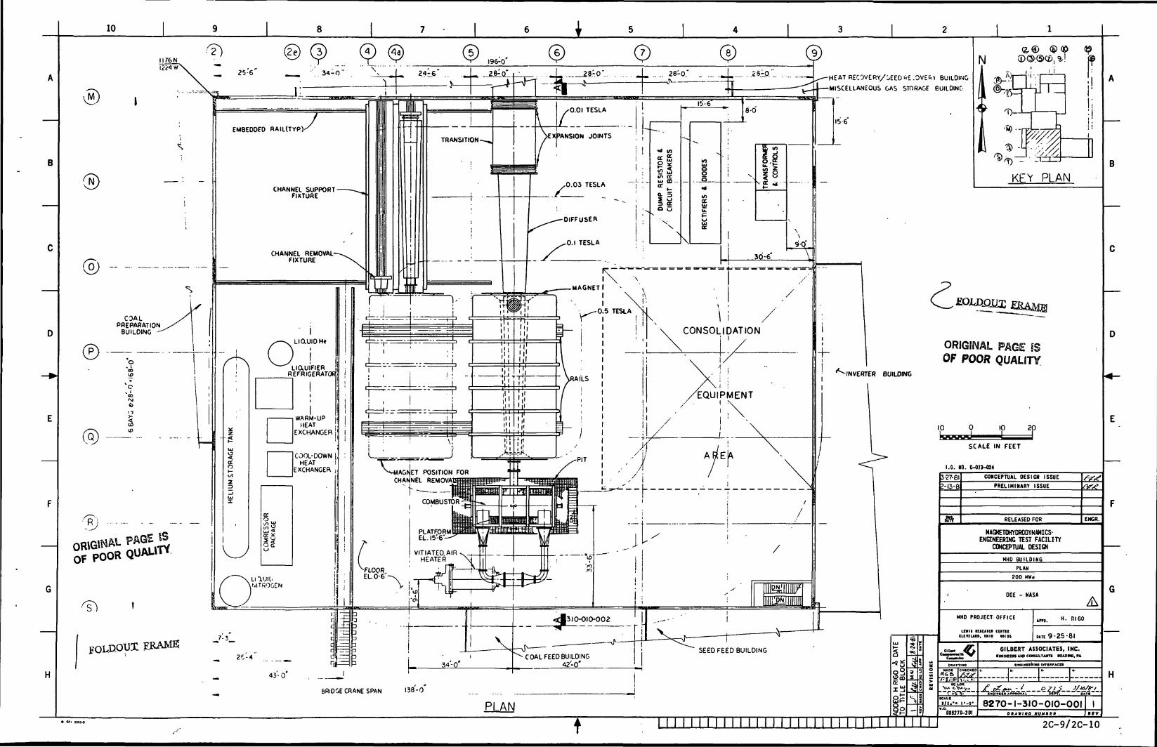
2S.-.P1. . ..
KFY PLAN
1 iCONSOLIDATION
COALPREPARATION
BUILDING
ORIGINAL PAGEOF POOR QUALITY
EQUIPMENT
POSITION FORCHANNEL REMOVA
HAGNETOHYDRODYNAHICS-ENQNEERING TEST FACILITY
CONCEPTUAL DESIGNVITIATED AIR , .,,
HEATER
FOLP.OUI BRAME GILBERT ASSOCIATES, INC.tmaaaaufcaeaaum nwwo. FA
BRIDGE CRANE SPAN 138-0
8270-I-3IO-OIO-OOI
2C-9/2C-10
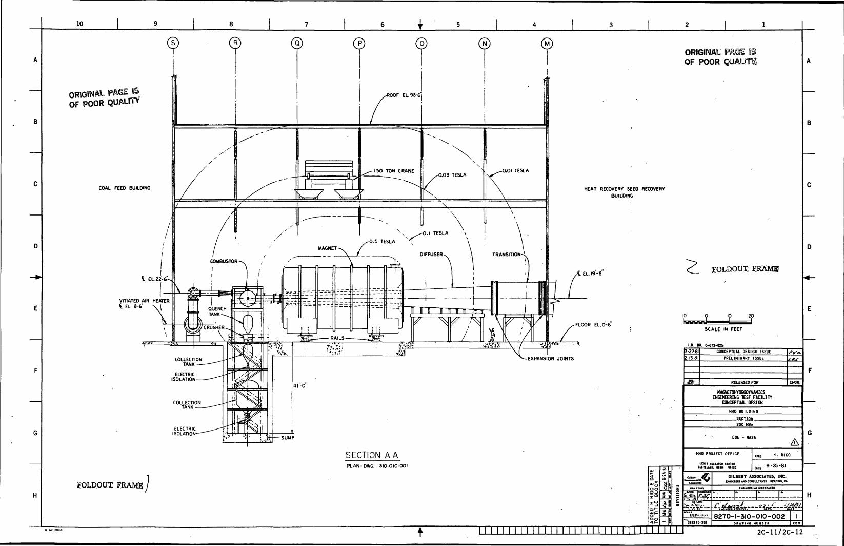
10
ORIGINAL PAGE SSOF POOR QUALITY
COAL FEED BUILDING HEAT RECOVERY SEED RECOVERY
BUILDING
I EL.aa'-6
VITIATED AIR HEATERt EL 8-6"
FLOOR EL. 0-6
EXPANSION JOINTS
ELECTRICISOLATION
SECTION A-APLAN-DWG. 310-010-001
EOL,D.OUJ: FRAME00o
1
ORIGINALOF POOR
HOLDOUT EK&MB
SCALE IN FEET
I.D. NO. C-073-W5
3-2781
2-13-81
CONCEPTUAL DESIGN ISSUE
PRELIMINARY ISSUE
RELEASED FOR ENCR.
MAGNETOHYDROOYN4MICSENGINEERING TEST FACILITY
CONCEPTUAL DESIGN
HMD BUILDING
SECTI OK
200 H»e
DOE - NASA
HMD PROJECT OFFICE
inm itiuio cumCUrtlWD. 0110 MIIS
088270-201
- "160
9-25-81
GILBERT ASSOCIATES, INC.EWMEen we CONSULTANTS READMO, M
H
8270-1-310-010-002 II""""
[gn«£jt 2C-11/2C-12
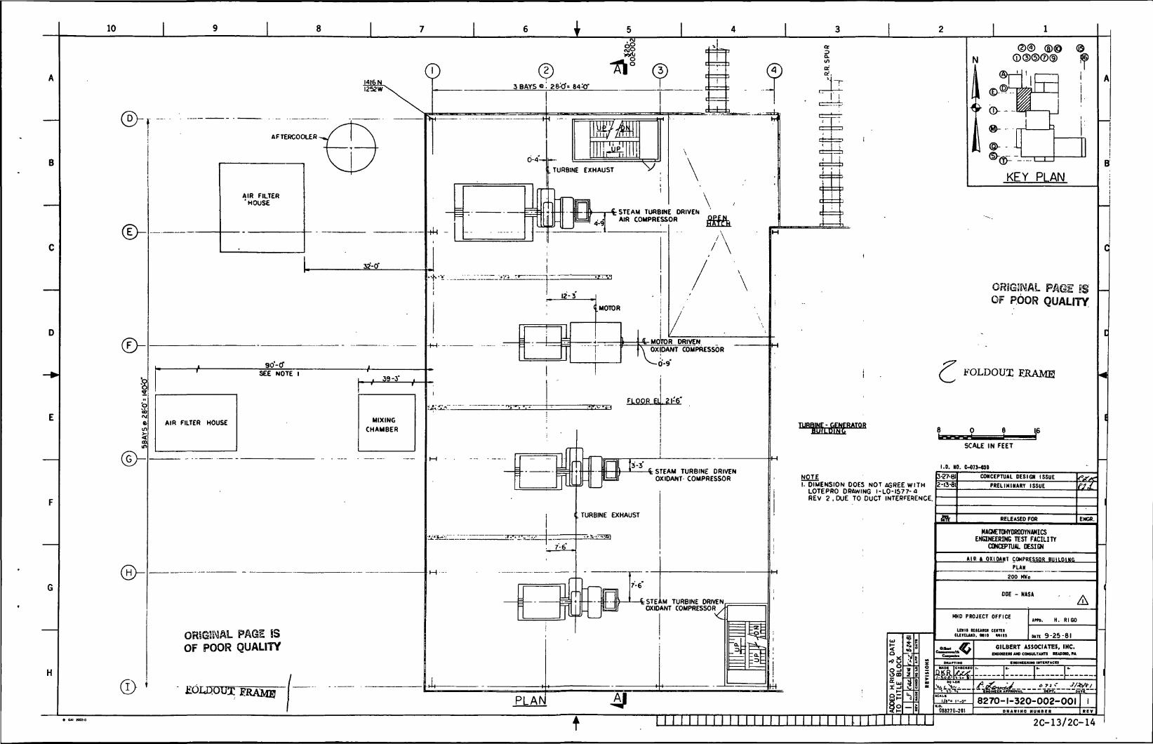
10
(D
STEAM TURBINE DRIVENAIR COMPRESSOR
9Q'-CfSEE NOTE I
AIR FILTER HOUSE
. 39-3'
MIXING
CHAMBER
OR5G3WAL PAGE IBOF POOR QUALITY
'
11
T
1
-1.....
.MOTOR ;
i
-4-MOTO
/
R DRIV\ OXIDANT COD
X_. rt'.o-
\
7-6"
STEAM TURBINE DRIVENOXIDANT COMPRESSOR
TURBINE EXHAUST
4 STEAM TURBINE DRIVENOXIDANT COMPRESSOR /I
PLAN
aIS)crcr.
N
B
KEY PLAN
PAGE ISOF POOR QUALITY
c FOLDOUX FJRAME
TURBINE - GENERATORE - GENEBiLEfcLk
I.D. MO. C-671-UO
NOTEI. DIMENSION DOES NOT AGREE WITH
LOTEPRO DRAWING I-LO-I577-4REV 2 , DUE TO DUCT INTERFERENCE.
Sai
2-13-81CONCEPTUAL DESIGN ISSUE
PRELIMINARY ISSUE
RELEASED FOR ENCfi.
MAGNETOHYDROOYNAMICSENGINEERING TEST FACILITY
CONCEPTUAL DESIGN
AIR » OXIDANT COMPRESSOR BUILDING
PLAN
200 MWe
DOE - NASA
MHD PROJECT OFFICE
inn IUU*G> teiTiio. me uns
tm. H. RIGO
wit 9-25-81GILBERT ASSOCIATES, IHC.
INOMEEM AW CflMULTAHn UACHO, PA
I •elKCKRIIla MTKIVACCS
8270-1-320-002-001D«A»mC MU«»BI»
' ' M I M I M M I I IT1 I M I M I TTI M I N N 2C-13/2C-14
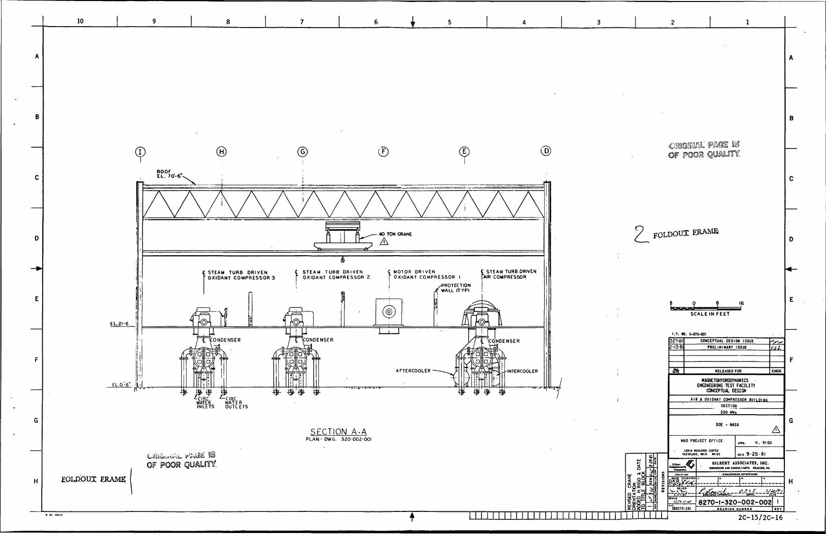
10 i
EL.21-6
EL.0-6
ERAME
© ®ROOF .EL. 70-6
STEAM TURB DRIVEN' OXIDANT COMPRESSORS
STEAM TURB DRIVENOXIDANT COMPRESSOR 2
MOTOR D R I V E NOXIDANT COMPRESSOR I
/PROTECTION/ WALL (TYP)
STEAM TURB DRIVEN'AIR COMPRESSOR
ONDENSER
^CIRC ^-CIRCWATER WATERINLETS OUTLETS
XJNDENSER
AFTERCOOLER
ONDENSER
HNTERCOOLER
SECTION A-APLAN-DWG. 320-002-001
^IGSKALOF POOIR
FOLD.OUI FJRAME
8 _ 16
SCALE IN FEET
I.1!. NO. C-073-031
I 1%
B-27-612-13-81
CONCEPTUAL DESIGN ISSUE
PRELIMINARY ISSUE
RELEASED FOR
MAGNETOHYDRODYNAMICSENGINEERING TEST FACILITY
CONCEPTUAL DESIGN
ENGR.
AIB i OXIDAHT COMPRESSOR BUILDIMfi
SECTION
200 MWe
DOE - NASA
MHO PROJECT OFFICE
LEVII KSEARClt CENTCICLfVElAMD. OHIO WHS
08B270-20I
un. H. RIGO
UTE 9-25-81
GILBERT ASSOCIATES, INC.EMOMZelB A1O CONSULTAHn UADtHO. PA
KMaiMCKKINO INTKRPACtl
8270-1-320-002-002D H A W I H O NUMBER
2C-15/2C-16
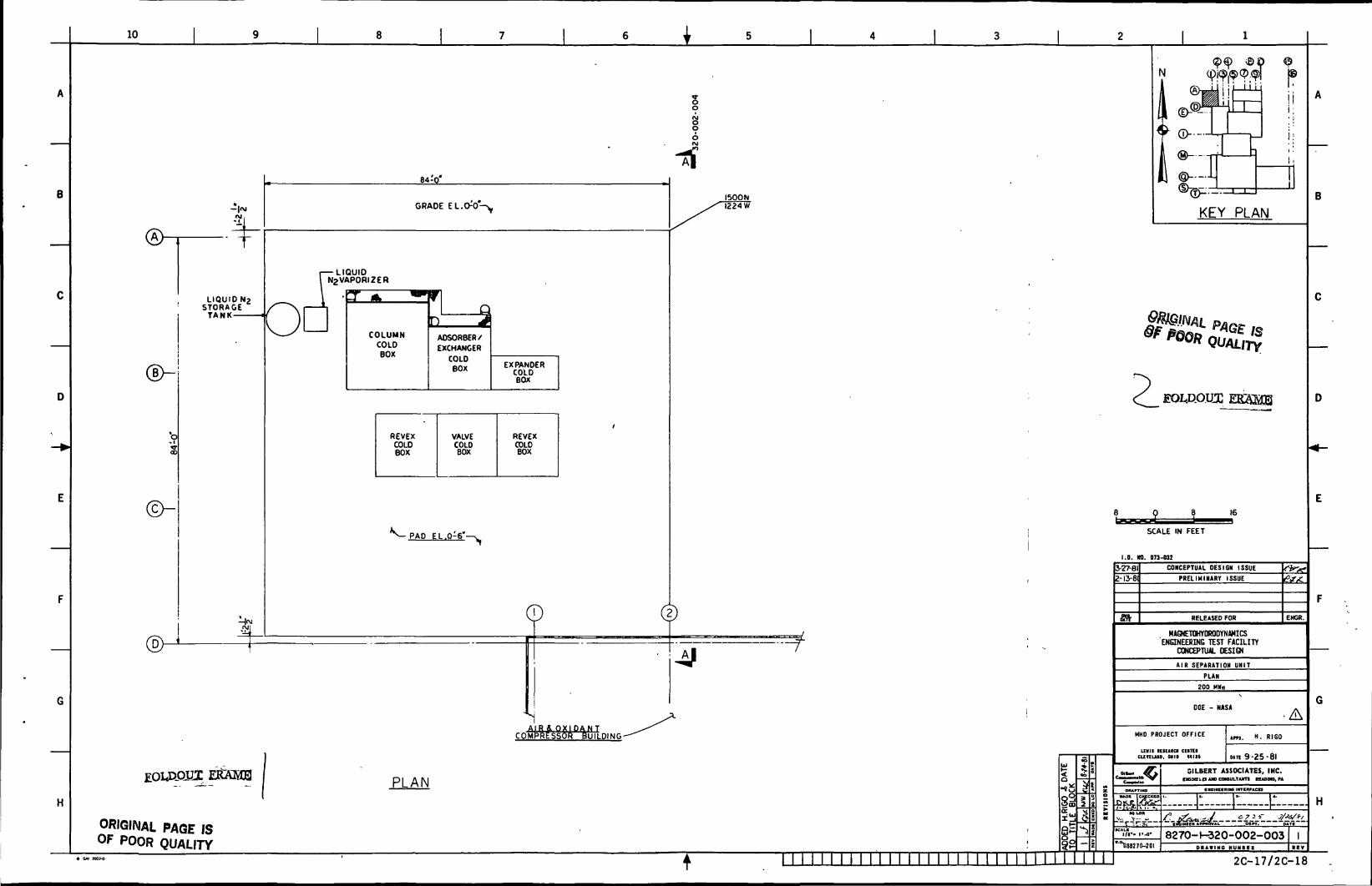
10 iSo
8o
-tfGRADE
•LIQUID
LIQUID N2
STORAGETANK
I LIUUIUI N2VAPORIZER
T A *^
COLUMN
COLDBOX
1 Q~> J
ADSORBER/
EXCHANGER
COLOBOX EXPANDER
COLDBOX
REVEXCOLDBOX
VALVECOLOBOX
REVEXCOLDBOX
PAD EL.O^S"-
1500 N1224 W
I I I
KEY PLAN
IS
SCALE IN FEET
1.0. NO. 073-032
AIR & pCOMPRESS
K I D A N T}R BUILDING-
H
EOUiQIiT
ORIGINAL PAGE ISOF POOR QUALITY
PLAN
3-27-81
2-13-81
CONCEPTUAL DESIGN ISSUE
PRELIMINARY ISSUE
RELEASED FOR
MAGNETOHYDRODYNtHICSENGINEERING TEST FACILITY
CONCEPTUAL DESIGN
AIR SEPARATION UNIT
PLAN
200 M*g
OOE - NASA
HHD PROJECT OFFICE
LEWIS IESUICI CEITCIcuvELjuo, MHO mn
©
ENGR.
im. H. RIGO
un 9-25-61
""iff l'-a-
"'"U882JO-20I
GILBERT ASSOCIATES, INC.BNOMZfc«S AW CONSULTAMn UADMO. M
8270-1-320-002-003PR*»IHO M U M B E B
H
T 2C-17/2C-18
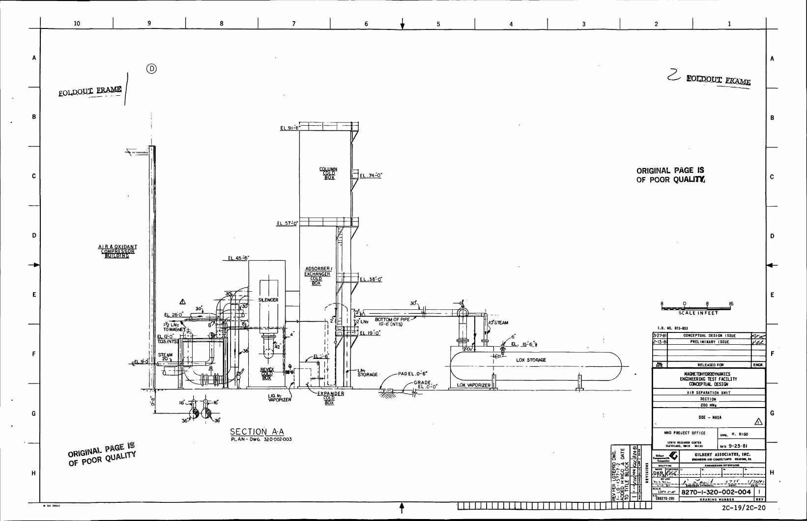
10 i
SECTION A-APLAN - OWG. 320-002-O03
BOTTOM OF PIPE -I9'-6"(NTS)
ORIGINAL PAGE ISOF POOR QUALITY,
0 8 _ 16
SCALE I N F E E T ~~
I.D. NO. 073-033
sSi 'TS
j-27-eiM3-8I
CONCEPTUAL DESIGN ISSUE
PRELIMINARY ISSUE
RELEASED FOR
MAGNETOHYDROOYNAHICSENGINEERING TEST FACILITY
CONCEPTUAL DESIGN
AIR SEPARATION UNIT
SECTION
200 MWe
DOE - NASA
MHO PROJECT OFFICE
inn luuia ceiniCliKUID, MIC HIIS
"'^8270-201
ENGR.
H. RI60
MTE 9-25-81
GILBERT ASSOCIATES, INC.IMMEEn AW COWULTAHn KAOMa. M
• NOINCKKIIW INTIMrACES
8270-1-320-002-004D R A W I N G NUMBER
t 2C-19/2C-20
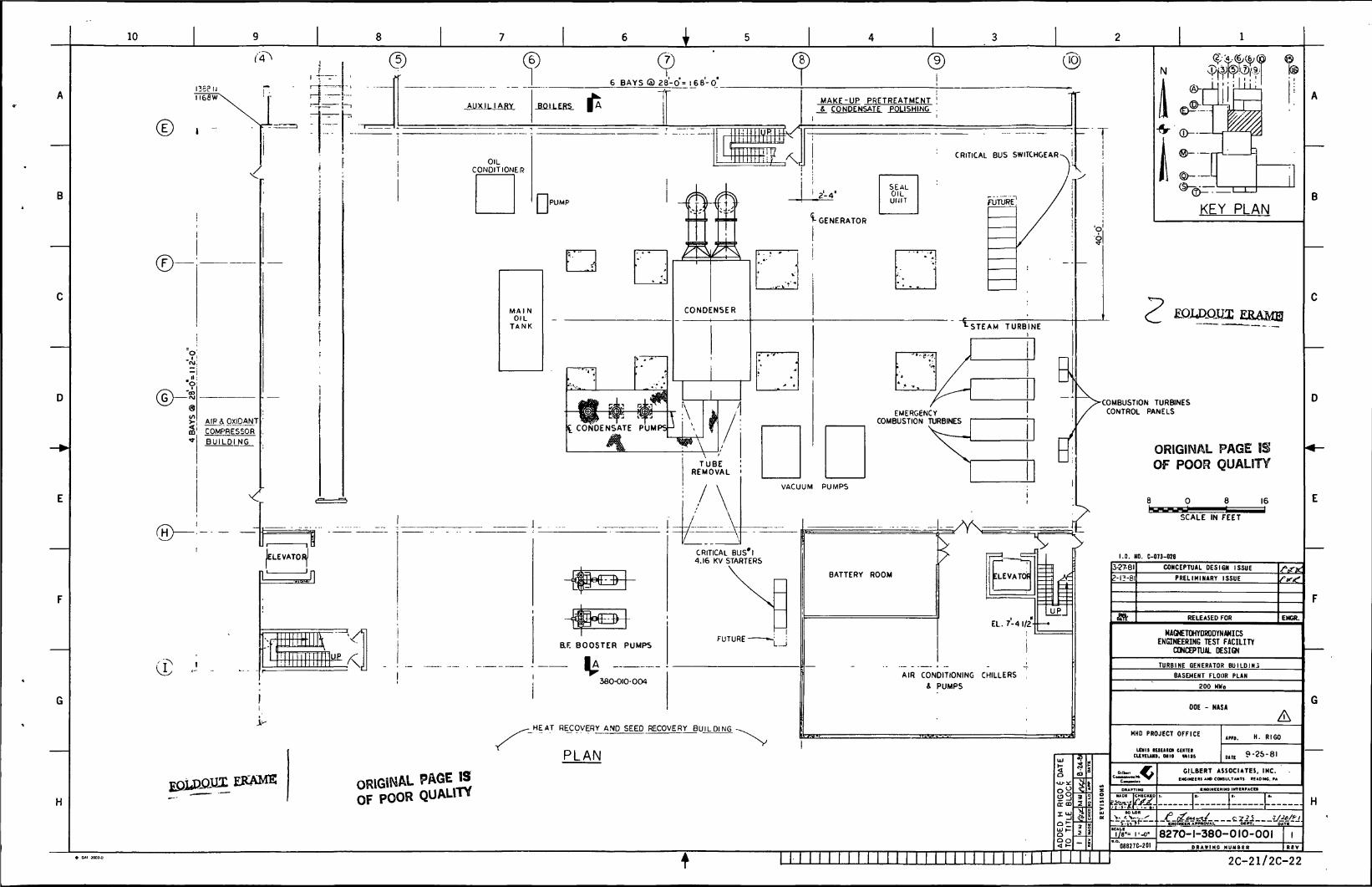
6 BAYS ® a8-0 = 168-0
MAKE-UP PRETREATMENT '_&. COMPENSATE POLISHING .
KEY PLAN
EQU3QIJX ERAME
>COMBUSTION TURBINESCONTROL PANELSEMERGENCY
COMBUSTION TURBINESC COMPENSATE
ORIGINAL PAGE ISOF POOR QUALITY
4.16 KV STARTERS
MAGNETOHYDRODYNAMICSENGINEERING TEST FACILITY
CONCEPTUAL DESIGN
AIR CONDITIONING CHILLERS
& PUMPS
RECOVERY AND SEED RECOVERY BUILDING
GILBERT ASSOCIATES, INC.NCINEERS AND CONSULTANT! READING. FAORIGINAL PAGE IS
OF POOR QUALITY
8270-1-380-010-001
2C-21/2C-22
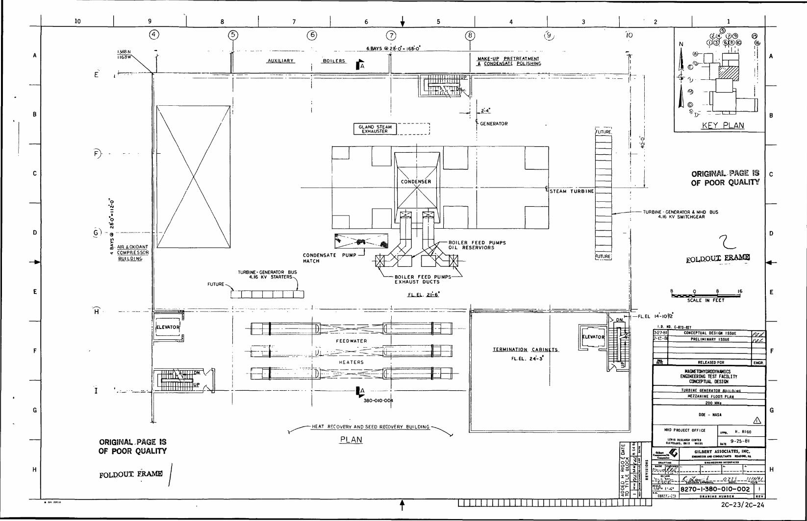
10
©I386Nlie
6 BAYS g>2J-o"- lesV.
AUXILIARY BOILERS
. AIR &OXIDANTCOMPRESSORBUILDING
H
MAKE-UP PRETREATMENT_4 COMPENSATE POLISHING
10
T
TURBINE-GENERATOR BUS4.16 KV STARTERS
.FUTURE.
©
N
J»-*•-/M) —
KEY PLAN
RBINE
i ~O
!l •?• -j- ;
ii
1
— - — ! — T
ORIGINAL-PAGE ISOF POOR QUALITY
TURBINE - GENERATOR A MHO BUS4.16 KV SWITCHGEAR
CONDENSATE PUMPHATCH
fUTURE;
FUTURE 1
-BOILER FEED PUMPS-EXHAUST DUCTS
FL.EL. 21-6
JELEVATORi'
FEEDWATER
W
r~H E A T E R S
• A
V380-OIO-0*4
OR!G3i\SAl PAGE ESOF POOR QUALITY
FOLD.OUX FRAME
-HEAT RECOVERY AND SEED RECOVERY BUILDING-
PLAN
TERMINATION CABINETS
FL.EL. 24-3
ELEVATOR
PH.*-|— FUEL
EBAMQ
SCALE IN FEET
14-10^2
1.0. NO. C-073-M7
2-12-81
I I ! I I I I I I I I I I I I I I I I I I I I I! I I I I
-u>^O^
5-27-81 CONCEPTUAL DESIGN ISSUE
PRELIMINARY ISSUE
RELEASED FOR ENGR
MAGNETOHYDROOYNWICSENGINEERING TEST FACILITY
CONCEPTUAL DESIGN
TURBINE GENERATOR BUILOiNB
MEZZANINE FLOPS PLAN
200 HWe
DOE - NASA
MHD PROJECT OFFICE
Lnil IEIUIU CUTEICUUUHD, OHIO MISS
H. RIGO
9-2S-6I
GILBERT ASSOCIATES, INC.tm«ienuDCOHsin.TA>in tauaa.n
H
8270-1-380-010-002D R A W I N G NUMBER
2C-23/2C-24
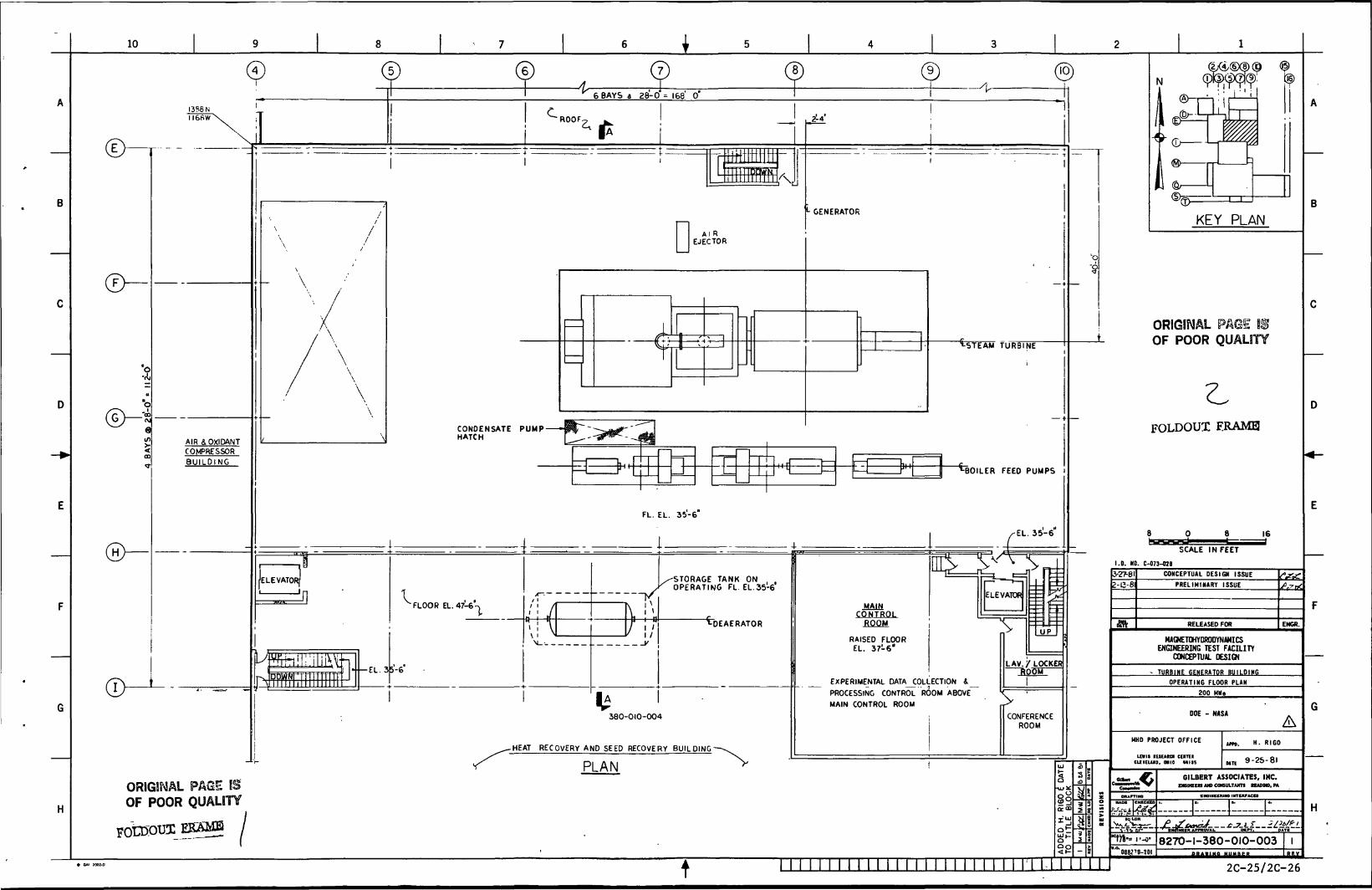
10
COMPENSATE PUMPHATCH
AIR &OXIDANTCOMPRESSORBUILDING
1JELEVATOR(
•
pi
T> !
i|
i^jfo! :!
1*0^r ii i...
l\s. :n_J
-EL. 3
^ FLOOR EL. 47-6'-v
5-6*
^ •i
"l \\ ^
X
/ !/'j/
/STORAGEr OPERATIN
CDEAERATOR
380-010-004
-HEAT RECOVERY AND SEED RECOVERY BUILDING-
PLAN
MAINCONTROL
ROOM
RAISED FLOOREL. 37-6"
EXPERIMENTAL DATA_COLLECTlON i_
PROCESSING CONTROL ROOM ABOVE
MAIN CONTROL ROOM
ELEVATOR
UP
LAV./LOCKER"ROOlir
CONFERENCEROOM
KEY PLAN
ORIGINAL mOF POOR QUALITY
cLFOLDOUX F.RAM0
SCALE IN FEET
1.0. NO. C-073-026
ORIGINALOF POOR
PAGE BSQUALITY
3-27-81
Z-C-81
CONCEPTUAL DESIGN ISSUE
PRELIMINARY ISSUE
RELEASED FOR ENGR.
HAOETOHYDRODYNWICSENGINEERING TEST FACILITY
CONCEPTUAL DESIGN
TURBINE GENERATOR BUILDING
OPERATING FLOOR PLAN
200 MKe
DOE - NASA
HMD PROJECT OFFICE
unit itiEKca cumCUKUID, MIO MIIS
HAOC CMXCKXO
H. RIGO
9-25-81
GILBERT ASSOCIATES, INC.IB «o camiLTwn KWHO.M•MINUKUM INTUtrACO
8270-1-380-010-003 I
* OAI 7002-D
t2C-25/2C-26
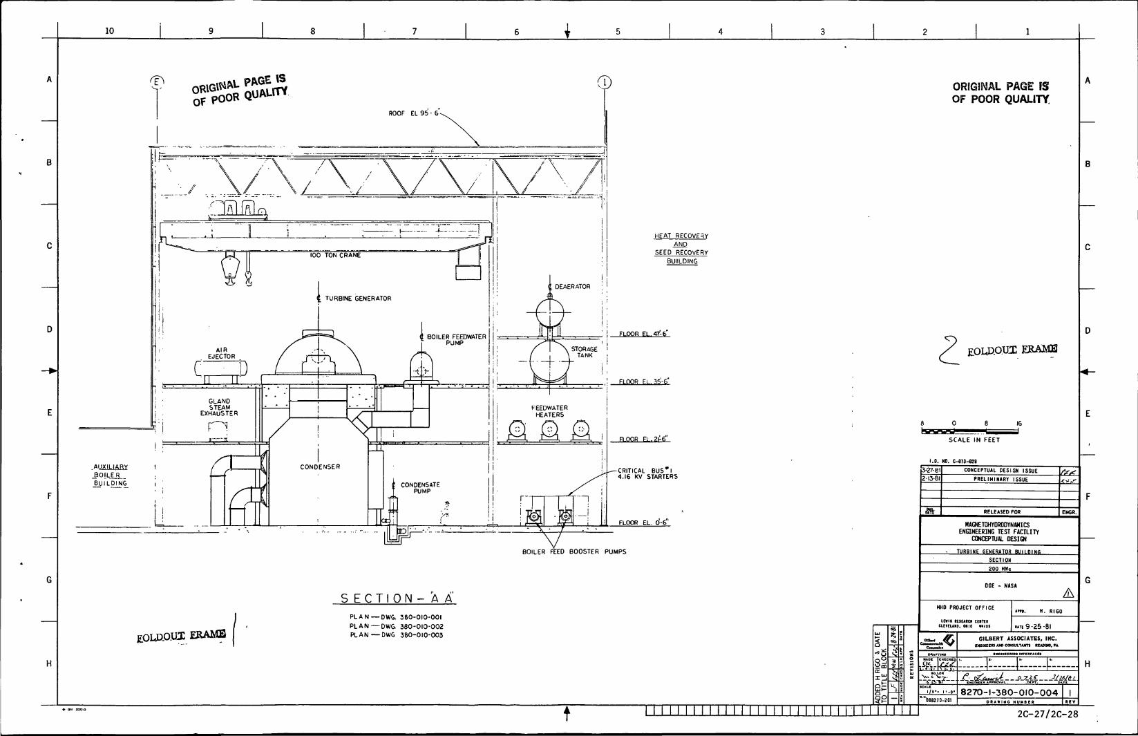
10
H
HEAT RECOVERY
ANDSEED RECOVERY
BUILDING
CRITICAL BUS* I4.16 KV STARTERS
BOILER FEED BOOSTER PUMPS
ERAME
S E C T I ON - A A
PLAN — DWG. 380-010-001
PLAN—DWG. 380-010-002
PLAN—DWG 380-010-003
ORIGINAL PAGE ISOF POOR QUALITY.
EBAMH
SCALE IN FEET
1.0. NO. C-073-02B
(3-27-81
§§
<r
2-13-81
fift
CONCEPTUAL DESIGN ISSUE
PRELIMINARY ISSUE
RELEASED FOR ENGR.
MAGNETOHYDRODYNAHICSENGINEERING TEST FACILITY
CONCEPTUAL DESIGN
TURBINE GENERATOR BUILDING
SECTION
200 HWe
OOE - NASA
MHD PROJECT OFFICE
LEIII lEIUm CEITCICLCtEUW. OHIO MIJ5
oiiv>t
jfer
'°OB8270-2CI
DUE 9-25-81
GILBERT ASSOCIATES, INC.CNCIXEERS AND CONSULTANTS BEADM8. PA
INOINeCKIMO INTCItrACCS
H
8270-1-380-010-004D R A W I N G N U M B E R
I
* QAI K02-D M M I M I I I M I I I I I I I M M II I II II 2C-27/2C-28
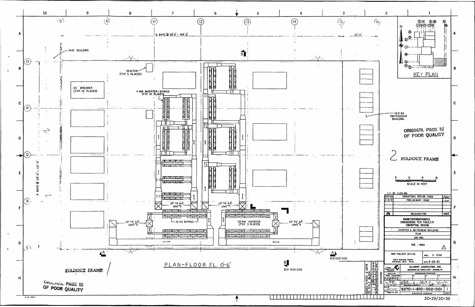
6 BAYS & 28-0 • 168-0
KEY PLAN
DC BREAKER(TYP. 10 PLACES)
13.8 KVSWITCHGEAR
BUILDING
FOL.DOU.T: FRAME
CONCEPTUAL DESIGN ISSUE
PRELIMINARY ISSUE
MAGNETOHYOROOYNAMICSENGINEERING TEST FACILITY
CONCEPTUAL DESIGN
INVERTER 4 SWITCHGEAR BUILDING
MHD PROJECT OFFICE
P L A N - F L O O R EL. 0-6' GILBERT ASSOCIATES, INC.IMOIHCERS AND CONSULTANT* RfADMO. PAEOJJIOJLLT ERAME
8270-1-810-002-001
2C-29/2C-30

10 I
ROOF EL. 48-0
FLOOR EL. 35-6"
FLOOR EL. 0-6
OF POOR QUALITY
ROOF FL.4fi'-O"
FLOOR EL 3 '-
(14)I
S E C T I 0 N - "A A"PLAN DWG. 810-002-001
fAX UNIT*4 , , A/t
\I ' l
<r
1 1
I '^
(
j lS; .
'
T
-
— -
if1
,X
1
UNIT*
K
2O MWINVERTER(TYR 2)
i*• — - D;J
AA
"l
V
|
1Ml "
Al
» 1 if
1
1
-f
--
• - — » r-j..
4MW INVE(TYP.
1
RTER4)
FLOOR EL.O-fi' J I
EOLAOHI S E C T I O N - B B'PLAN DWG 810 002 001
7
^
\
A/t UNIT'S
' " 1
1
1
1
( \
1LJ2
!;
i |l
LfL
!
i
A/C UN IT "2
-T—
-UL,h
y ^T
20 MW
i
INVERTER
4\t ^s
i
A/t UNIT"|
i
r 1*A
It
1
f 4-IN
20 MW \t
- 1
JVERTER
1V2
1
/yt UNIT "4
1
1 '
\ -1
1!
!
\
,
, 1! ;
j
i i
' 7 ORIGINAL PAGE $<§OF POOR QUALITY
ERAMS
1.0. NO. C-07J-M5
g00
rm
3-27-a2 1381
fflV.
CONCEPTUAL DESIGN ISSUEPRELIMINARY ISSUE
RELEASED FOR EHGfi.
MAGNETOHYDROOYNAMICSENGINEERING TEST FACILITY
CONCEPTUAL DESIGN
INVERTER BUILDING
SECTION
800 MWe
DOE - NASA
MHD PROJECT OFFICE
inn IEIUICI cuniCUKUID, MIO Hl»
•ADI CHCCKKO
CALK
I/I'' I'-l)'
088270-20)
trn. H. RIGO
wit 9-25-81GILBERT ASSOCIATES, INC.
nn«KnAW»Mun.Tum KAODO. PA
• NelNlftlim INTIKPACU
---r—P--. H
8270-1-810-002-002DBA»IMO MUMBE«
t 2C-31/2C-32
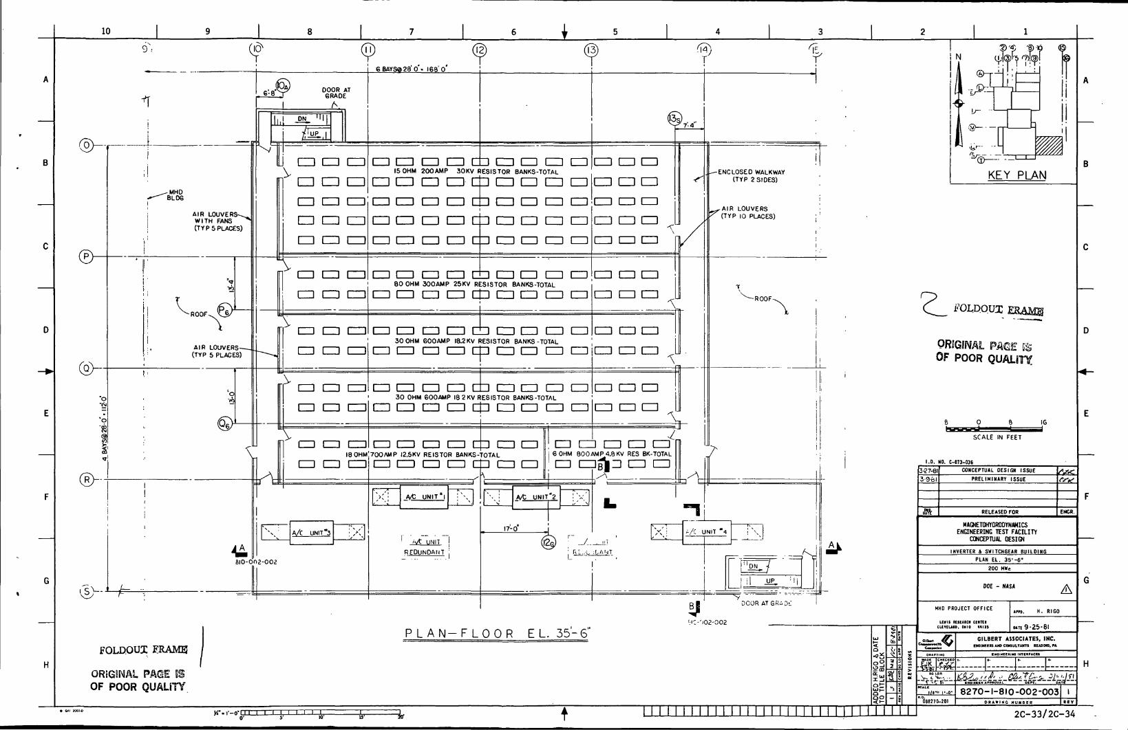
10
"8
®~
BLOS
AIRWITH FANS(TYP 5 PLACES)
-ROOF
AIR LOUVERS—(TYP 5 PLACES)
6 BAYS® 28'Q'- I68'o'
DOOR ATGRADE
A
CD CD CD
CD CD CD
mi CD en CD CD CD CD15 OHM 200AMP 30KV RESISTOR BANKS-TOTAL
CD CD CD CDCDCD
CD CD CD CD CD
I I I I
CD CD
\CD CD CD
CD CD CD
\1=) CD CD
CD CD CD CD
CD CD CD CD
CD CD CD
CD CD CD CD
CD CD CD CD
CD CD CD CD
CD CD CD 1=1
CD CD CD 1=1
CD CD CD
CD CD CD
CD 1=1 CD
CD CD CD
CD CD 1=1
CD80 OHM 300AMP 25KV RESISTOR BANKS-TOTAL
3 CD CD CD CD CD CD CD
1=1 CD CD CD CD CD CD CD
1=1 CU CD
CD CD CD
CD L=) CD
CD CD
\1=1 CD [=1
CD CD CD
30 OHM 600AMP 18.2 KV RESISTOR BANKS-TOTAL
CD CD CD CD CD CD CD CDiCD CD
L=l CD CD CD CD CD CD CD
H\ cm a CD
18 OHM
CD CD CD
30 OHM 600AMP 18 2KV RESISTOR BANKS-TOTAL
CD CD CD CD LOP CD CD CD
CD CD CD CD dp CD CD700AMP I2.5KV REISTOR BANKS-TOTAL
CD CD CD CD dD CD CD
%x A/C UNIT'S. \ S
Bio-ona-ooa
A/C UNIT*I
CD CD CD
CD CD CD
CD CD CD CD CD6 OHM 800 AMP 4.8 KV RES BK-TOTAL
JM1L !
REDUNDANT i
A/t UNIT*2
17-0'
CD CDel^ CD CD
FOLD.OUI ERAME
OREGSNAL PAOE Si
OF POOR QUALITY
P L A N - F L O O R EL. 35-S"
ORfGIIW
OF POOR QUALITY
ENCLOSED WALKWAY(TYP 2 SIDES)
AIR LOUVERS(TYP 10 PLACES)
FOLDQUX E8AMS
I.D. NO. C-073-036CONCEPTUAL DESIGN ISSUE
PRELIMINARY ISSUE
RELEASED FOR
MAGNETOHYDRODYNAMICSENGINEERING TEST FACILITY
CONCEPTUAL DESIGN
INVERTER 4 SWITCHBEAR BUILDINGPLAN EL. 35'-6"
200 MWe
DOE - NASA
ENCR.
H. RIGO
O.TE 9-25-81
GILBERT ASSOCIATES, INC.EKGWCERS AND COHSULTAMTS REAOINO. PA
CNOINEEftlNO IMTKMFACU
:..-j:--r-—I:--.8270-1-810-002-003
D R A W I M C NUMBtR
Vi-.i'-nTTI I I I I I I
t2C-33/2C-34
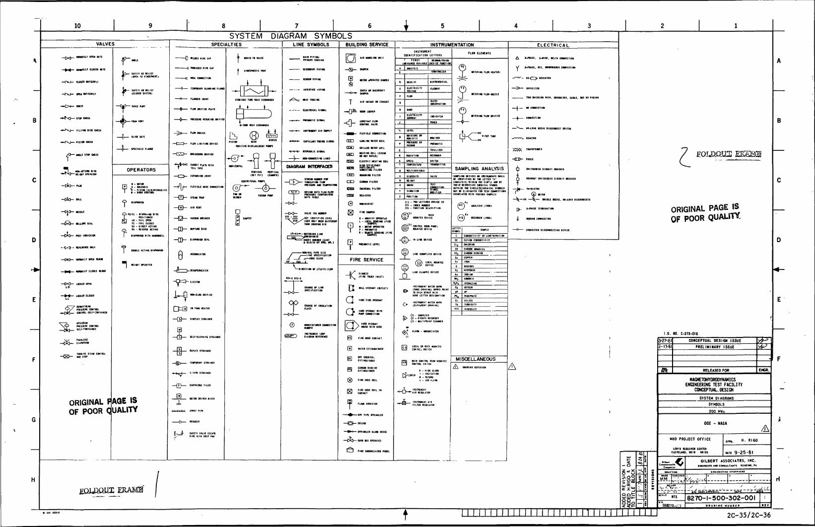
10
VALVES
MUI IPtt WTI
CUSID Minim
TIIIIK DISC CMC*
unf iie» MCI
Tl m-«im ii n••"TxJ— Wig,T oHmnm
-C)O— nut
—CM- «EOLE
— &&- mien mi
— (XJ— FOST i»i»ra
— t»3-- KKHMCt «W
—OK}— HMMLLT oro am
— 1«4 — MMWLIT C10UD Hill
—CO— LOMEO OK»
m\9*n CWTML
PflEIjURE CONTIUL
Vi> PACK k.ESS-0%-. OI.»R*CN
ORIGINALOF POOR
^»fEIT 03 HllEfiDpfv 10 *TMsna
M— tmn 01 uiiEfy {CLOUD WSIE«)
ftfl MEE Nil
—lfj-.OU.«t
-4- IMCTkCU FL««
OPERATORS
?
fo/fc - Di»Mk»ai tintrasuioNU
m * FAIL OKNi! FC - Fill CLOSED
01 - DIRECT ACTINGM - IH«Kl UTING
IITH lUHDWfIL
T1 -
DOUBLE ACtINC 01
FAQE ISQUALITY
SYSTEM DIAGRAM SYMBOLSSPECIALTIES LINE SYMBOLS
•EUKO PIPE CAP
| TMEAOEO PIPE CAP
NBSi COM CTI OH
TENPeum ILAUIHC FIANCE
FLAKED JOINT
FLOI ORIFICE PLATE
PMSSORf REDUCING ORIFICE
FlOt NOIZIE
FLO! UNITING DEVICE
lltOT PunTELL TAU
E1PUSION JOINT
—riff-
— Q —
FUtllLE HOSE CONNECTION
OIAPMUGN SEAL
8
NON-CLOG ORIFICE
IN TANA KEAtER
SELF-CLEANING STRAINER
DUPLEI STRAINER
TEMPORARY STRAINER
T-TIPt STRAIRER
CARTRIDGE FILER
NOTOR DRIVER HIIIR
AINCSPKEHIC VEHT
j LIITERFAa 'IHRC
y^X^ NEAt TIACIMC
ELECTtlCU SIOUL
*•••*. PMOMTIt SI9UL
-0—0— IHSnUKMT AIR IWfLT
MfcHu upiiuun TWIN iieui
DIAGRAM NTERFACES
.—rx. STHM IUKR FOV—4 3 J>— 1AUUTIK FUN
—^ PHSSURE AMD TEMPT M TDK
(_ Jl 7 ) OEIIOI OATI FLM P101V •* PtESSni TEBPEUTStE
UTA UIU
-cxj-
, r IDENTIFIER (KIP)s iUIOXUSEO ONLT WEN DIFFERENT
THAN DURING KID
-01 NEC! I ON DF (FLUID) FlM
in-i in-i
© MNUFACTURER OMCCTION•r UB
BUILDING SERVICE
All NMDLING UNIT
INSTRUMENTATION
1NSIIUNCMT
IDENIIFICITION LETTERS
(DEVICE FUHCTIOI[ ANAHSIS
T-0*
run
IEHC.1
CEZD
cn
H
run HI CONNECTION
COOLING Wilt COIL
CNILLEO MTER COIL
MM IK COIL (SHUM HOT Mill)
ELECTRIC NEAT'NG COIL
ILTH
m Mini
I Flirt*
ML FILTH
OUlSTH
WHIDISTAT
FIRE SERVICE
aaO
•All HYDRANT (OUTLET)
TARD FIRE HVOKANT
HOUSE IITH HOSE
FIRE KOSE CABIkET
•ATER EITINGUISMER
DRV CHEHICALE1TINGUISKER
FLANE ARRESTOR
-OR PIPI SPRINKLER
DELUGE
SPRtNKLER ALAR1 CHEO
—CX}— CURi MI OPfMIED
C-J FIRE ANWmmnt
HULTtVARIAILE
(I) - TIO LETTEtED OtVICE ID(t) - INOEI HUMER(t) - FUHC1ION DESCRIPTION
LIKE CONNfLIED DEVICE
® LOUl X
"""
LINE CtUPED DEVICE
€>tHSIBUHENT NATCH URR(SANE DM me) HARKS POINTTO EACH OTHER ItTHSAME LETTER OESICIUTION
(C - CONPUIER<l - EVENTS RECORDER(S - BULTIPOINT SCANNER
H - HIGH ALARMI - INDICATION
R - RECORD
. & .•°~U—^A
FLO! ELENENTS
y^ KTERIK FLOI v
• THING F101 NOZILE
• TfllW FLOW ORIFICE
SAMPLING ANALYSIS
UWPLING DEVICE! M IttlWKHTS SHALLK IDENTIFIED II THE UTTEI '*"(IMLTSIS) fltHIH TW ClfTU AMD ITIWH KSMCIIVE QCIICIL ITRSQLOUTSIDE THE CIRCLEfUCKEHICll STttOLS1*T •£ ELIIIIUTED FOt IEM CONNECTIONSISSOCIATEO ura rutious SAWLC*
ANALYZER (IKM)
CITION CONDUCTIVn
IITOM
USEOUS
HTOROCEH
SODIUM
MISCELLANEOUS
A
ELECTRICAL
A t-rusE. s-*m. HitA ctBKTiaN
Y 1-P11SI. ITI. •NBttlKl CMMECIIOH
_AAAA_ tl-T~t- HIHTII
Dl UPACIIIR
TUI aittltl PttP. OlMCItl. CAtLE. MS It Hill
—L— M cmrECitM
—^ CINNECTltt
X NI-IOAO IREAI •ItCtMECI niTCN
-r*~ -u IEACTDR
^^ TRAHSFDR1ER
—fl~n— FtSES
nilCHREAR ClffCOIT UEAKER
IIAIMT 1IMCNIEAI CllCUtl MEHEI
—-U— TRTRISm
" ©.,.,—)S(—IR —B^— BtaiLE ItfAI. NO-LIID BlfCflMIECTS
^ I-PRASE TERIINATim
4- tROBNO CINNECTIM
»>— COMECT8I BISCMNECTIHI IEVICE
A
EOJJiDJLCG 12
ORIGINAL PAGE ISOF POOR QUALITY.
1.0. ND. C-373-016
JEQUQQ1II
2
CjQt
2-13-81
ffk
CONCEPTUAL DESIGN ISSUE
PRELIMINARY ISSUE
RELEASED FOR
HAGNETGHYDRODYNAMICSENGINEERING TEST FACILITY
CONCEPTUAL.DESIGN
SYSTEM DIAGRAMS
SYMBOLS
200 HWe
DOE - NASA
MHO PROJECT OFFICE
mil IEIEUCI CEITIIo, mio «i»
068270-;:
ENGR.
H. RIGO
9-25-81
GILBERT ASSOCIATES, INC.iNGnatm AW CONSUITAMTI IEAOINC. r*
INOINCIHINO nrrc*r*cct
-Z_
8270-1-500-302-001D R A W I N G HUMBtBU.
t
I I I I 2C-35/2C-36

10 I
EVAPORATIONI 3.888,000 GPO
(2,700 GPM)
NOTES:
I
SLOWDOWN1008,OOO.GPOCTOOGPM)
914.400 GPO(1635 GPM)
100,800 GPD(70 GPM)DEMINERALIZER
144,000 GPD(100 GPM)REGENERATION A
WASTE14.400 GPD00 GPM)
DISCHARGE TOSURFACE WATI
28,800 GPD(20GPM
CYCLE LOSSES21.600 GPD(15 GPM)
BOILERSLOWDOWN50,400 GPO(35 GPM)
93,600 GPD(63 GPM)
AVG. RATE237,600 GPD
(165 GPM)WASTEHOLDING
TANK
FILTER "SOJDGETRUCK OFF SITE144,060 GPD OOOGPMASH (SLAG)
TRUCK „OFF SITE ' (LESS THAN IGPM)
ASH/SLUDGE TOOFF-SITE DISPOSAL AREA
ANNUAL AVG14,400 GPD(10 GPM)
ANNUAL AVG14,400 GPD
(10 GPM)
ALL FLO* RATES SHOWN ARE DESIGN FLOWRATES,EXCEPT AS NOTED.
SANITARY WASTE FLOW BASED ONPOPULATION OF 200 AT MAIN MHD PLANT,20 AT COAL HANDLING FACILITIES AND35 GALLONS PER CAPITA PER DAY.
ORIGINALOF POOR
£QUQQUX ERAME
ORIGINAL PAGE IS
OF POOR QUALITY
AMOISTURE IN ASH/SLUDGE
144,000 GPD000 GPM)
RUNOFF IN EXCESS OFONCE-IN-10YEAR, 24 HOUR RAINFALL
1,166,400. GPD(eio GRM)
^DISCHARGE TOSURFACE WATERS
T I I I I I I I I I I I I I I I I I I I I I I I I I N II I II II
I.D. MO. C-373-049
3-17-81
CONCEPTUAL DESIGN ISSUE
PRELIMINARY ISSUE
RELEASED FOR ENCR.
MAGNETOHYDRODYNAMICSENGINEERING TEST FACILITY
CONCEPTUAL DESIGNFLUID SYSTEM DIAGRAM
WATER BALANCE
200 HWe
DOE - NASA
MHD PROJECT OFFICE
UWI9 IESEMOI CMTEIcuvcuao, OMIO wiis
MAO! [CK1C1CCO
«ER I iB"f-tmx-F,-
HOIIE
'"186270-201
um. H. RIGO
»n9-25-8lGILBERT ASSOCIATES, INC.
tHBMECBS AW CONSUtTAMn nADMO, M
• NetNUIWM mTERTACn
8270-1-550-318-001IHO jjuiiaga
H
2C-37/2C-38

1. Report No.NASA CR-165452 - Vols . IT-11I
4. Title and SubtitleMAGNETOHYDRODYNAMICS ENGINF.ERIN200 MWe POWER PLANTCONCEPTUAL DESIGN ENGINEERING &
2. Government Accession No. I 3. Recipient's Catalog No.
3 TEST FACILITY (MHD-ETF)
EPORT (CDER)
7. Author(s)Gilbert/Commonwealth
9. Performing Organization Name and AddressGilbert /CommonwealthReading, PA 19603 /
12. Sponsoring Agency Name and Address N.
U. S. Department of Energy |Office of Magnetohydrodynamics ,'Washington, D.C. 20545
5. Report Date
September 19816. Performing Organization Code
8. Performing Organization Report No.
10. Work Unit No.
11. Contract or Grant No.
DEN 3-224
13. Type of Report and Period Covered
Contractor Report
14. Sponsoring Agency Report No .DOE/NASA/0224-1
15. Supplementary Notes
Final Report. Prepared under Interagency Agreement DE-AI01-77ET10769. Project Manager,Henri S. Rigo, MHD-ETF Systems Office, NASA Lewis Research Center, Cleveland, Ohio 44135.
16. Abstract
This report summarizes the reference conceptual design of the MHD Engineering Test Facility(ETF), a prototype 200 MWe coal-fired electric generating plant designed to demonstrate thecommercial feasibility of open cycle MHD. Main elements of the design are identified andexplained, and the rationale behind them is reviewed. Major systems and plant facilities arelisted and discussed. The report also presents construction cost and schedule estimates,and identifies tlie engineering issues that should be reexamined. This report integrates thelatest (1980-1981) information from the MHD technology program with the elements of aconventional steam power electric generating plant. It is presented in five volumes:
Vol. I - Executive SummaryVol. II - EngineeringVol. Ill - Costs & ScheduleVol. IV and Vol. V - Supplementary Engineering Data (Issues, Background, Performance
Assurance Plan, Design Details, System Design Descriptions andRelated Drawings).
17. Key Words (Suggested by Author(sl)Magnetohydrodynamics engineering test facilityConceptual design engineering report CDERPower plant200 MWe
19. Security Classif. (of this report)
Unclassified
18. Distribution StatementUnclassified - unlimitedSTAR Category 44DOE Category UC-90g
20. Security Classif. (of this page) 21. No. oUnclassified 145
f Pages 22. Price'A07
* For sale by the National Technical Information Service. Springfield. Virginia 22161