Embed Size (px)
Citation preview

Magnetic Fusion Power Plants
Farrokh Najmabadi,Director, Center for Energy ResearchProf. of Electrical & Computer EngineeringUniversity of California, San Diego
EPRI, July 19, 2011

Conceptual designs studies of fusion power plants are performed by the ARIES national team
National ARIES Team comprises key members from major fusion centers (universities, national laboratories, and industry).
Many studies of evolving confinement concepts and different technologies.

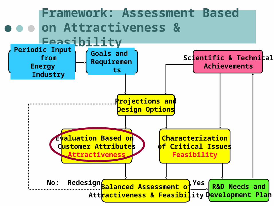
Framework: Assessment Based on Attractiveness & Feasibility
Periodic Input fromEnergy Industry
Goals and Requirements
Scientific & TechnicalAchievements
Evaluation Based on Customer Attributes
Attractiveness
Characterizationof Critical Issues
Feasibility
Projections andDesign Options
Balanced Assessment ofAttractiveness & Feasibility
No: RedesignR&D Needs and
Development Plan
Yes

Utility/industrial advisory committees have defined customer requirements
Fusion Power Plant Studies Utility Advisory Committee and EPRI Fusion Working Group* Chaired by Steve Rosen & Jack Kaslow respectively, Met biannually in 1993-1995. Helped define goals and top-level requirements. Had a major impact on safety/licensing as well as
configuration/maintenance approach.
Input as members of review committee for individual designs.
* See http::/aries.ucsd.edu/ARIES/DOCS/UAC/ for membership and meeting minutes.

Goals & Top-Level Requirements for Fusion Power Plants Were Developed in Consultation with US Industry
Have an economically competitive life-cycle cost of electricity
Gain Public acceptance by having excellent safety and environmental characteristics· No disturbance of public’s day-to-day activities · No local or global atmospheric impact· No need for evacuation plan· No high-level waste· Ease of licensing
Reliable, available, and stable as an electrical power source· Have operational reliability and high availability· Closed, on-site fuel cycle· High fuel availability· Available in a range of unit sizes
Fu
sion
ph
ysic
s &
tec
hn
olog
y
Low-activation material
Fusion Fuel Cycle

Framework: Assessment Based on Attractiveness & Feasibility
Periodic Input fromEnergy Industry
Goals and Requirements
Scientific & TechnicalAchievements
Evaluation Based on Customer Attributes
Attractiveness
Characterizationof Critical Issues
Feasibility
Projections andDesign Options
Balanced Assessment ofAttractiveness & Feasibility
No: RedesignR&D Needs and
Development Plan
Yes

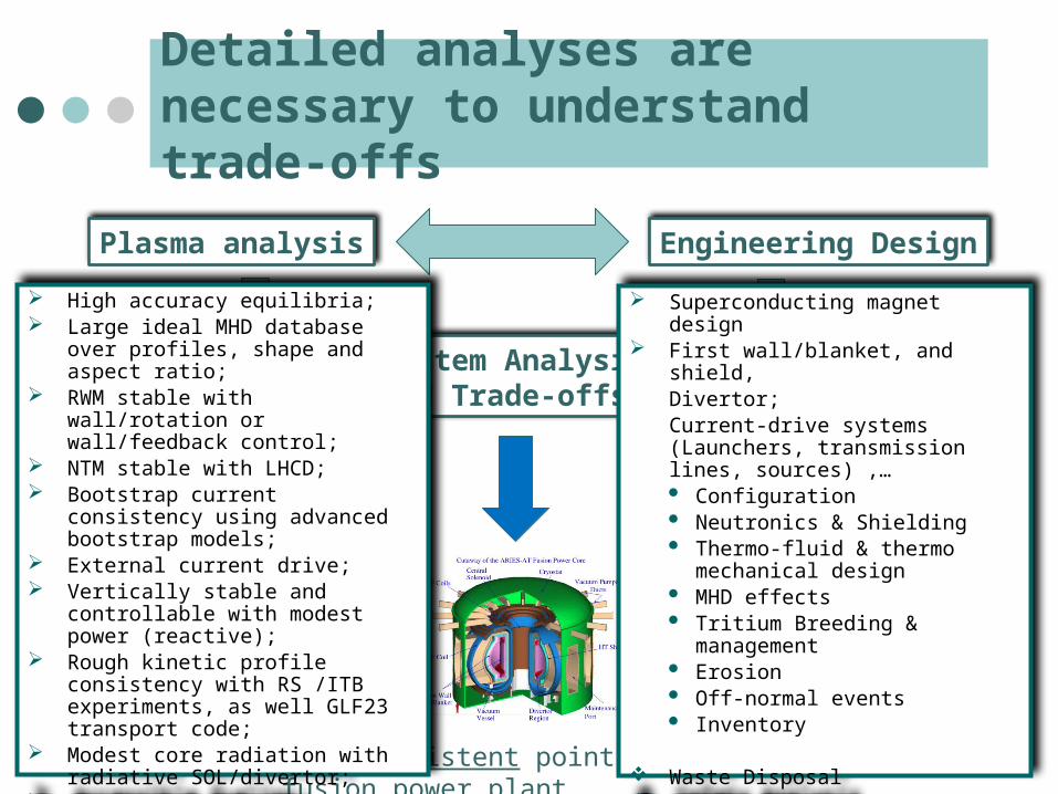
Detailed analyses are necessary to understand trade-offs
Plasma analysis Engineering Design
Self-consistent point design for a fusion power plant
System Analysis and Trade-offs
Detailed analyses are necessary to understand trade-offs
Plasma analysis Engineering Design
Self-consistent point design for a fusion power plant
System Analysis and Trade-offs
High accuracy equilibria; Large ideal MHD database over
profiles, shape and aspect ratio; RWM stable with wall/rotation or
wall/feedback control; NTM stable with LHCD; Bootstrap current consistency using
advanced bootstrap models; External current drive; Vertically stable and controllable with
modest power (reactive); Rough kinetic profile consistency with
RS /ITB experiments, as well GLF23 transport code;
Modest core radiation with radiative SOL/divertor;
Accessible fueling; No ripple losses; 0-D consistent startup;
Superconducting magnet design First wall/blanket, and shield,
Divertor;Current-drive systems (Launchers, transmission lines, sources) ,…· Configuration· Neutronics & Shielding· Thermo-fluid & thermo mechanical
design· MHD effects· Tritium Breeding & management· Erosion· Off-normal events· Inventory
Waste Disposal Safety Analysis Maintenance

DT Fusion requires a tritium-breeding blanket
Plasma should be surrounded by a blanket containing Li
Through care in design, only a small fraction of neutrons are absorbed in structure and induce radioactivity* Rad-waste depends on the choice of material: Low-
activation material For liquid coolant/breeders (e.g., Li, LiPb), most of fusion
energy (carried by neutrons and n-Li reaction) is directly deposited in the coolant simplifying energy recovery
Issue: Large flux of high-energy neutrons through the first wall and blanket:
D + T 4He (3.5 MeV) + n (14 MeV)
n + 6Li 4He (2 MeV) + T (2.7 MeV)nT
* A neutron multiplier, e.g., 7Li, Pb, or Be, is needed to achieve tritium self-sufficiency.

Irradiation leads to a operating temperature window for material
Additional considerations such as He embrittlement and chemical compatibility may impose further restrictions on operating window
Radiation embrittlement
Thermal creep
Zinkle and Ghoniem, Fusion Engr. Des. 49-50 (2000) 709
Carnot=1-Treject/Thigh
Structural Material Operating Temperature Windows: 10-50 dpa

New structural material should be developed for fusion application
Candidate “low-activation” structural material: Fe-9Cr steels: builds upon 9Cr-1Mo industrial experience and materials database
9-12 Cr ODS steel is a higher-temperature option. SiC/SiC: High risk, high performance option (early in its development path) W alloys: High performance option for PFCs (early in its development path)

1) Ceramic Solid Breeder Concepts (using He coolant and ferritic steel structure) • Adopted from fission pebble-bed designs.• Complex internal design of coolant routing
to keep solid breeder within its design window.
• High structural content, low Li content, requires lots of Be multiplier.
• Low outlet temperature and low efficiency• Large tritium inventory
Many Blanket Concepts have been considered
2) Li (breeder and coolant) with vanadium structure • Needs insulating coating for MFE (MHD
effects).• Special requirements to minimize threat of
Li fires.• Large tritium inventory in Li which can be
released during an accident.
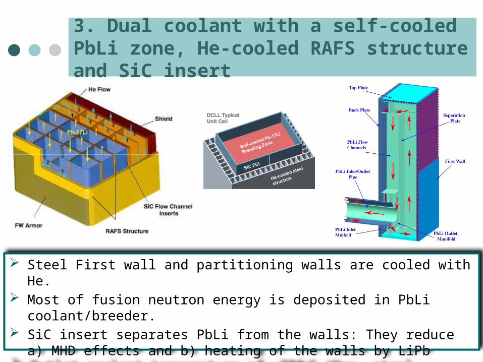
3. Dual coolant with a self-cooled PbLi zone, He-cooled RAFS structure and SiC insert
Steel First wall and partitioning walls are cooled with He. Most of fusion neutron energy is deposited in PbLi coolant/breeder. SiC insert separates PbLi from the walls: They reduce a) MHD effects and
b) heating of the walls by LiPb Outlet coolant temperature of ~700oC (Max. steel temperature of ~550oC)
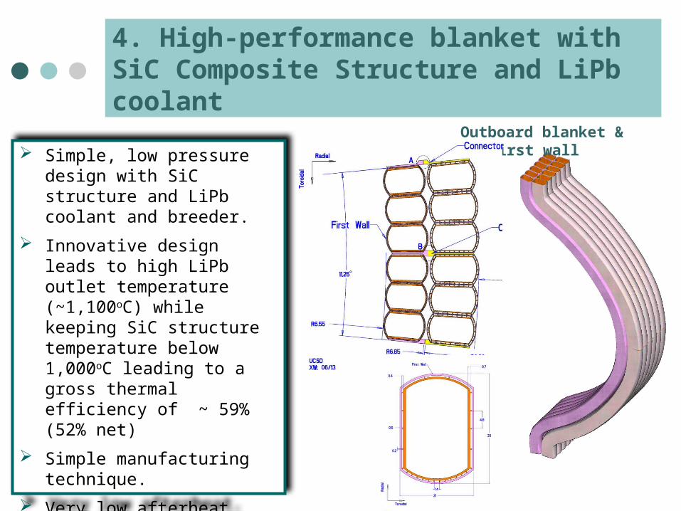
Outboard blanket & first wall
4. High-performance blanket with SiC Composite Structure and LiPb coolant
Simple, low pressure design with SiC structure and LiPb coolant and breeder.
Innovative design leads to high LiPb outlet temperature (~1,100oC) while keeping SiC structure temperature below 1,000oC leading to a gross thermal efficiency of ~ 59% (52% net)
Simple manufacturing technique.
Very low afterheat.
Class C waste by a wide margin.
Framework: Assessment Based on Attractiveness & Feasibility
Periodic Input fromEnergy Industry
Goals and Requirements
Scientific & TechnicalAchievements
Evaluation Based on Customer Attributes
Attractiveness
Characterizationof Critical Issues
Feasibility
Projections andDesign Options
Balanced Assessment ofAttractiveness & Feasibility
No: RedesignR&D Needs and
Development Plan
Yes

Configuration & Maintenance

ARIES-AT (tokamak) Fusion Core

The ARIES-AT utilizes an efficient superconducting magnet design
On-axis toroidal field: 6 T Peak field at TF coil: 11.4 T
TF Structure: Caps and straps support loads without inter-coil structure;
On-axis toroidal field: 6 T Peak field at TF coil: 11.4 T
TF Structure: Caps and straps support loads without inter-coil structure;
Superconducting Material Either LTC superconductor (Nb3Sn
and NbTi) or HTC Structural Plates with grooves for
winding only the conductor.
Superconducting Material Either LTC superconductor (Nb3Sn
and NbTi) or HTC Structural Plates with grooves for
winding only the conductor.

Configuration & Maintenance are important aspects of the design
1. Install 4 TF coils at a times
2. Insert ¼ of inner VV and weld
3. Complete the torus4. Insert maintenance
ports and weld to inner part of VV and each other
5. Install outer walls and dome of the cryostat
vacuum vesselInner part: 4 pieces, Complete vessel, outer part iswelded during assembly entirely made of maintenance ports

Modular sector maintenance enables high availability
Full sectors removed horizontally on rails Transport through maintenance corridors to hot
cells Estimated maintenance time < 4 weeks
ARIES-AT elevation view

ARIES-AT Fusion core is segmented to minimize rad-waste and optimize functions
Shield
Shield
Inboard FW/blanket
1st Out-board FW/blanket
2nd Out-board FW/blanket
Stabilizing shells
Divertor
Blanket-2 and shield are life-time components
Safety, Licensingand Waste Disposal

10-7
10-6
10-5
10-4
10-3
10-2
10-1
100
101
104 105 106 107 108 109 1010 1011
ARIES-STARIES-RS
Act
ivit
y (C
i/W th
)
Time Following Shutdown (s)
1 mo 1 y 100 y1 d
After 100 years, only 10,000 Curies of radioactivity remain in the585 tonne ARIES-RS fusion core.
After 100 years, only 10,000 Curies of radioactivity remain in the585 tonne ARIES-RS fusion core.
SiC composites lead to a very low activation and afterheat.
All components of ARIES-AT qualify for Class-C disposal under NRC and Fetter Limits. 90% of components qualify for Class-A waste.
SiC composites lead to a very low activation and afterheat.
All components of ARIES-AT qualify for Class-C disposal under NRC and Fetter Limits. 90% of components qualify for Class-A waste.
Ferritic SteelVanadium
Radioactivity levels in fusion power plantsare very low and decay rapidly after shutdown
Level in Coal AshLevel in Coal Ash

Safety analysis of off-normal events and accident scenarios indicate no evacuation plan is needed
Detailed accident analysis (e.g., loss of coolant, loss of flow, double break in a major coolant line) are performed: Limited temperature excursion due to the use of low-
activation material. No evacuation plan is needed. Most of the off-site dose after
an accident is due to tritium release from fusion core. Fusion core tritium inventory is ~ 1kg.
Components are designed to handle off-normal events: Pressurization of blanket modules due internal break of He
channels (Dual-cooled blanket) Disruption forces and thermal loads Quench of TF coils

Waste volume is modest (ARIES-AT)
0
50
100
150
200
250
300
350
400
Blanket Shield VacuumVessel
Magnets Structure Cryostat
Cu
mu
lati
ve
Co
mp
ac
ted
Wa
ste
Vo
lum
e (
m3
)
1,270 m3 of Waste is generated after 40 full-power year of operation. Coolant is reused in other power plants 29 m3 every 4 years (component replacement), 993 m3 at end of service
Equivalent to ~ 30 m3 of waste per full-power operation. Effective annual waste can be reduced by increasing plant service life.
0
200
400
600
800
1000
1200
1400
Class A Class C
Cumu
lative
Comp
acted
Was
te Vo
lume (
m3)
90% of waste qualifies for Class A disposal
90% of waste qualifies for Class A disposal
Costing

A cost break-down structure is used.
Costing is performed through a comprehensive cost break-down structure to component level.
Direct vendor quotes are used when available.
In the absence of vendor quotes, comparable technologies are used to cost a component.
Costing assumptions where calibrated against advanced fission and fossil plant economics.*
No. Account20 Land and Land Rights21 Structures and Site Facilities22 Power Core Plant Equipment 22.01 Fusion Energy Capture and
Conversion 22.01.01 First Wall and Blanket 22.01.02 Second Blanket 22.01.03 Divertor Assembly 22.01.04 High Temperature Shielding 22.01.05 Low Temperature Shielding 22.01.06 Penetration Shielding 22.02 Plasma Confinement 22.02.01 Toroidal Field Coils 22.02.02 Poloidal Field Coils 22.02.03 Feedback Coils 22.03 Plasma Formation and
Sustainment 22.04 …. 22.1423 Turbine Plant Equipment24 Electric Plant Equipment25 Miscellaneous Plant Equipment 26 Heat Rejection Equipment27 Special Materials90. Direct Cost91-98 Indirect Costs99. Total Cost
*J. Delene, Fusion Technology, 26 (1994) 1105.

Magnetic Fusion Power Systems are projected to be cost-competitive.
Estimated Cost of Electricity (2009 c/kWh)
Conservative Plasma
Advacned Tokamak
Advanced Technology
0
2
4
6
8
10
12
14
Major radius (m)
ARIES-I ARIES-RS ARIES-AT0
2
4
6
8
Total Capital Cost ranges from $4B to $8B. We are in the process of implementing Gen IV fission cost data base. This data
base would lead:· Similar total Capital Cost· 30% lower COE because of a lower fixed-cost rate (5.8% for Gen-IV vs 9.65%
for Delene).
Total Capital Cost ranges from $4B to $8B. We are in the process of implementing Gen IV fission cost data base. This data
base would lead:· Similar total Capital Cost· 30% lower COE because of a lower fixed-cost rate (5.8% for Gen-IV vs 9.65%
for Delene).

Framework: Assessment Based on Attractiveness & Feasibility
Periodic Input fromEnergy Industry
Goals and Requirements
Scientific & TechnicalAchievements
Evaluation Based on Customer Attributes
Attractiveness
Characterizationof Critical Issues
Feasibility
Projections andDesign Options
Balanced Assessment ofAttractiveness & Feasibility
No: RedesignR&D Needs and
Development Plan
Yes

Level Generic Description
1 Basic principles observed and formulated.
2 Technology concepts and/or applications formulated.
3 Analytical and experimental demonstration of critical function and/or proof of concept.
4 Component and/or bench-scale validation in a laboratory environment.
5 Component and/or breadboard validation in a relevant environment.
6 System/subsystem model or prototype demonstration in relevant environment.
7 System prototype demonstration in an operational environment.
8 Actual system completed and qualified through test and demonstration.
9 Actual system proven through successful mission operations.
Technical Readiness Levels provides a basis for assessing the development strategy
Incr
ease
d in
tegr
atio
n
Incr
ease
d F
idel
ity o
f en
viro
nmen
t
Bas
ic &
App
lied
Sci
ence
Pha
se
Validation Phase
See ARIES Web site: http://aries.ucsd.edu/aries/ (TRL Report) for detailed application of TRL to fusion systems

Fusion Nuclear technologies are in an early development stage
Fusion research has focused on developing a burning plasma. Technology development has been based on the need of
experiments as opposed to what is needed for a power plant.
Plasma support technologies (e..g, superconducting magnets) are at a high-level of technology readiness level.
Fusion Nuclear technologies, however, are at a low level of technology readiness level. Material development has only focused on irradiation
response of structural material due to the low level of funding. A focused development program could raise the TRL levels of
fusion nuclear technologies rapidly.

Example: TRLs for Plasma Facing Components
Issue-Specific Description Facilities
1System studies to define tradeoffs and requirements on heat flux level, particle flux level, effects on PFC's (temperature, mass transfer).
Design studies, basic research
2 PFC concepts including armor and cooling configuration explored. Critical parameters characterized.
Code development, applied research
3Data from coupon-scale heat and particle flux experiments; modeling of governing heat and mass transfer processes as demonstration of function of PFC concept.
Small-scale facilities:e.g., e-beam and plasma simulators
4Bench-scale validation of PFC concept through submodule testing in lab environment simulating heat fluxes or particle fluxes at prototypical levels over long times.
Larger-scale facilities for submodule testing, High-temperature + all expected range of conditions
5Integrated module testing of the PFC concept in an environment simulating the integration of heat fluxes and particle fluxes at prototypical levels over long times.
Integrated large facility:Prototypical plasma particle flux+heat flux (e.g. an upgraded DIII-D/JET?)
6Integrated testing of the PFC concept subsystem in an environment simulating the integration of heat fluxes and particle fluxes at prototypical levels over long times.
Integrated large facility: Prototypical plasma particle flux+heat flux
7 Prototypic PFC system demonstration in a fusion machine.Fusion machineITER (w/ prototypic divertor), CTF
8 Actual PFC system demonstration qualification in a fusion machine over long operating times.
CTF
9 Actual PFC system operation to end-of-life in fusion reactor with prototypical conditions and all interfacing subsystems.
DEMO
Power-plant relevant high-temperature gas-cooled PFC
Low-temperature water-cooled PFC

Application of TRL to Power Plant Systems

Application to power plant systems highlights early stage of fusion nuclear technology development
TRL
1 2 3 4 5 6 7 8 9Power management Plasma power distribution Heat and particle flux handling High temperature and power conversion Power core fabrication Power core lifetime Safety and environment Tritium control and confinement Activation product control Radioactive waste management Reliable/stable plant operations Plasma control Plant integrated control Fuel cycle control Maintenance
Completed In Progress
For Details See ARIES Web site: http://aries.ucsd.edu/aries/ (TRL Report)
Basic & Applied Science Phase
System demonstration and validation in operational environment (FNF) Demo/1st power plant

ITER will provide substantial progress in some areas (e.g., plasma, safety)
TRL
1 2 3 4 5 6 7 8 9Power management
Plasma power distribution
Heat and particle flux handling
High temperature and power conversion
Power core fabrication
Power core lifetime
Safety and environment
Tritium control and confinement
Activation product control
Radioactive waste management
Reliable/stable plant operations
Plasma control
Plant integrated control
Fuel cycle control
Maintenance
Completed In Progress ITER
Absence of power-plant relevant fusion nuclear technologies severely limits ITER’s contributions in many areas.
Absence of power-plant relevant fusion nuclear technologies severely limits ITER’s contributions in many areas.
System demonstration and validation in operational environment (FNF) Demo/1st power plant

In summary:
ITER will demonstrate “technical feasibility” of fusion power by generating copious amount of fusion power (500MW for 300s) with fusion power > 10 input power.
Tremendous progress in understanding plasmas has helped optimize plasma performance considerably.
Vision of attractive magnetic fusion power plants exists which satisy customer requirements.
Transformation of fusion into a power plant requires considerable R&D in material and fusion nuclear technologies (largely ignored or under-funded to date). This step, however, can be done in parallel with ITER

Thank You!