Embed Size (px)
Citation preview
Neil Marks; DLS/CCLRC Power Converters CAS, Warrington, May 2004
Magnet Power Converters and Accelerators
Neil Marks,DLS/CCLRC,
Daresbury Laboratory,Warrington WA4 4AD,
U.K.

Neil Marks; DLS/CCLRC Power Converters CAS, Warrington, May 2004
ContentsThe accelerator lattice.
Magnets:• dipoles;• quadrupole;• sextupoles.
Magnet excitation requirements.
The magnet/power converter interface:• number of turns in the coils;• current density in the conductor;• optimisation of magnet length and field strength.

Neil Marks; DLS/CCLRC Power Converters CAS, Warrington, May 2004
Accelerator MagnetsThe magnets control the direction and size of the beams of the circulating beam:Dipoles - bend and steer the beams;Quadrupoles - focus the beams;Sextupoles - control the focusing of ‘off
momentum’ particles (chromaticity);
All together they make up the ‘lattice’.

Neil Marks; DLS/CCLRC Power Converters CAS, Warrington, May 2004
A Cell in a LatticeA Separated Function Lattice:
F-Quad
D-Quad
F-Sext
D-Sext
Dipole
Cell Layout

Neil Marks; DLS/CCLRC Power Converters CAS, Warrington, May 2004
A typical ‘C’ cored Dipole
Other arrangements for dipoles:
‘H’ cores;
‘window frame’.

Neil Marks; DLS/CCLRC Power Converters CAS, Warrington, May 2004
H core and window-frame magnets‘H core’:
‘Window frame’:

Neil Marks; DLS/CCLRC Power Converters CAS, Warrington, May 2004
Dipole requirementsThe dipole magnets need:
• high field homogeneity.
The dipole power circuit needs:• stringent current continuity in the dipole circuit;• high current stability;• high current accuracy;• low ripple;• smooth current waveform (no discontinuities in I
or dI/dt)

Neil Marks; DLS/CCLRC Power Converters CAS, Warrington, May 2004
Flux density distribution in a dipole.

Neil Marks; DLS/CCLRC Power Converters CAS, Warrington, May 2004
Dipole field homogeneity on beam axis
Homogeneity expressed as ∆B/B = {B(x,y)-B(0,0)}/B(0,0); typically ± 1:104
within the ‘good field region’ defined by the beam transverse dimensions.
Neil Marks; DLS/CCLRC Power Converters CAS, Warrington, May 2004
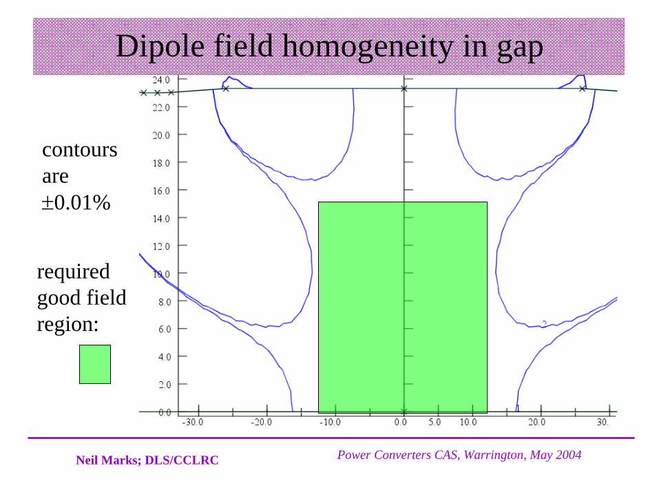
Dipole field homogeneity in gap
contours are ±0.01%
required good field region:

Neil Marks; DLS/CCLRC Power Converters CAS, Warrington, May 2004
Field continuity between DipolesThe dipoles in a lattice must have strong string current continuity (~ 1:104 or better):
• series connection (apart from very large accelerators – LHC for e.g.);
• low current leakage through cooling water and other parallel paths;
• low earth capacitance in a.c. accelerators (see presentation on ‘Cycling Accelerators’.

Neil Marks; DLS/CCLRC Power Converters CAS, Warrington, May 2004
Dipole Current StabilityIn a synchrotron:•the particles are ‘trapped’ in a potential well around a point on the rising side of the r.f. waveform (non-relativistic beam);•low energy particles arrive late - more r.f. volts – more acceleration (phase stability);•dipole field controls beam energy;•gradient discontinuities can disrupt phase stability.
Vrf
synchronous phase (non relativistic particles).

Neil Marks; DLS/CCLRC Power Converters CAS, Warrington, May 2004
Quadrupole magnetsThe quadrupoles focus the beam; there must be at least two types in the lattice:
• ‘F’ types which focus horizontally, defocus vertically;
• ‘D’ types which defocus horizontally, focus vertically.
Quadrupoles have similar requirements as dipoles, with high stability power supplies; they must be very accurately aligned.

Neil Marks; DLS/CCLRC Power Converters CAS, Warrington, May 2004
Quadrupole fields
x
By
The field is zero at the centre and varies linearly with horizontal and vertical position. Off-centre particles are focused (or defocused); particles on the central orbit are undeviated (but misplacement of the magnetic centre results in horizontal or vertical beam bending).

Neil Marks; DLS/CCLRC Power Converters CAS, Warrington, May 2004
Assessment of quadrupole gradient quality
-0.1
-0.05
0
0.05
0.1
0 4 8 12 16 20 24 28 32 36
x (mm)
∆ d
Hy/
dx (%
)
y = 0 y = 4 mm y = 8 mm y = 12 mm y = 16 mm
graph is percentagevariation in dBy/dx vs x at different values of y

Neil Marks; DLS/CCLRC Power Converters CAS, Warrington, May 2004
‘Diamond’quadrupole cross section.

Neil Marks; DLS/CCLRC Power Converters CAS, Warrington, May 2004
Effect of current instabilities.Quadrupoles must ‘track’ the dipoles (ie energy):
• they control the machine Q value - current variation could engage a resonance - beam loss - stabilities of the order of 1:104 are usually needed;
• they control the beta values in the lattice – current variation results in variation in beam size.
In many accelerators the quadrupoles are connected in series in ‘families’ (F and D for example).In others (synchrotron sources for example) they are individually powered (separate power converters!) to give local control of beta values (beam size):

Neil Marks; DLS/CCLRC Power Converters CAS, Warrington, May 2004
Sextupoles
00 x
By
The field and field gradient are zero at the centre; the field varies with a square law with horizontal and vertical position. Off-momentum (and therefore off-centre) particles see a gradient field and are therefore focused (or defocused); particles on the central orbit are undeviated and unfocused.

Neil Marks; DLS/CCLRC Power Converters CAS, Warrington, May 2004
Sextupole functionalitySextupoles are included in many lattices to control
chromaticity:
• there are usually ‘H’ (controlling horizontal chromaticity) and ‘V’ type sextupoles in a lattice;
• the H and V are usually series connected in ‘families’.• must also track the dipoles if field varies;• but are often less critical than quadrupoles (depends on
lattice configuration).
Are useful for including ‘correction’ dipole fields (and others) with auxiliary windings separately powered.

Neil Marks; DLS/CCLRC Power Converters CAS, Warrington, May 2004
Combined function magnetsSome or all quadrupole field can be combined into dipoles-bending and focusing in the same magnet (but relative strengths cannot be adjusted!).
x
Characterised by 'field index' n(+ or – depending on gradient).
n = - {ρ/B0}{dB/dx};
where ρ is radius of curvature or beam;B0 is central field in the magnet.

Neil Marks; DLS/CCLRC Power Converters CAS, Warrington, May 2004
Magnet excitation - Dipolescurl H = j;∫ H.ds = NI;(Hi)λ + (Hg)g = NI;Hi = B/(µµ0) (small);Hg = B/µ0 (larger);B = µ0 NI /(g + λ/µ);
Amp –turns:NI = B (g + λ/µ )/ µ0 ;NI ≈ B g / µ0 µ >> 1.
µ >>
g
λ
1
NI/2
NI/2
magnet gap: g; flux path in yoke: λ;steel permeability: µ (>>1); total turns in 2 coils: N;excitation current: I; field (A/m) in yoke: Hi;field (A/m) in gap: Hg; flux density in gap: B (assumed constant)

Neil Marks; DLS/CCLRC Power Converters CAS, Warrington, May 2004
Reluctance and low permeability.
NI = B (g + λ/µ )/ µ0
gap ‘reluctance’ yoke ‘reluctance’
The magnet designed must limit the Amp-turns lost in the yoke by limiting the flux density in the steel:
• use wider top, bottom and back legs;
•diverge the pole if necessary.

Neil Marks; DLS/CCLRC Power Converters CAS, Warrington, May 2004
Relative permeability of low silicon steel
10
100
1000
10000
0.0 0.5 1.0 1.5 2.0 2.5
B (T)
µ
Parallel to rolling direction Normal to rolling direction.

Neil Marks; DLS/CCLRC Power Converters CAS, Warrington, May 2004
Typical values of non-linearity.In low and medium field (≤ 1.5 T) dipoles, the yoke
reluctance should not exceed 2 ~ 3% of gap reluctance.
At values of B above 1.5 T, µ begins to fall rapidly; the magnet is becoming non-linear; current has to be increased to overcome the non-linearity.
Above 1.9 T, µ is typically less than 100 (depending on steel type); yoke reluctance will exceed 5%. The dipole is becoming saturated. The power converter will need to provide significant extra current and power.

Neil Marks; DLS/CCLRC Power Converters CAS, Warrington, May 2004
Excitation in Quads and Sextupoles.
For inscribed radius R, and ignoring yoke reluctance;
Amp – turns per pole:
Quadrupole:NI = Gq R2/ 2 µ0;
Sextupole:NI = Gs R3/3 µ0;
R
where: Gq is quadrupole gradient (T/m);Gs is sextupole gradient (T/m2).

Neil Marks; DLS/CCLRC Power Converters CAS, Warrington, May 2004
The magnet/power converter interface.Parameters to be chosen/optimised to ensure magnet/power converter compatibility:
• number of turns per magnet;• current density in the conductor;• length/field strength of the magnet.
In ‘conventional’ (not s.c.) magnets, these optima are determined by financial as well as technical issues. In s.c. magnets, the interface is technical (and financial!).

Neil Marks; DLS/CCLRC Power Converters CAS, Warrington, May 2004
Number of turns - relationshipsFixed:
beam energy;total Ampere-turns in coil: (NI);conductor current density: j;
Therefore:current I ∝ 1/N;cross section/turn: A = I/j ;
∝ 1/N;coil resistance: R ∝ N/A;
∝ N2 ;power loss: W = I2 R;
∝ (1/N)2 N2;independent of N!

Neil Marks; DLS/CCLRC Power Converters CAS, Warrington, May 2004
Number of turns - consequencesAdvantages of large N:
• lower I – power converter current is decreased;• less loss in transformers, rectifiers, cables.
Disadvantages of large N:• higher voltage on converter, cables, magnets terminals;• coil conductor content remains constant but inter-turn
insulation increases – coil becomes more larger .
So, choice of N is a compromise between magnet design and power converter design.

Neil Marks; DLS/CCLRC Power Converters CAS, Warrington, May 2004
Examples of typical turns/currentFrom the Diamond 3 GeV synchrotron source:Dipole:
N (per magnet): 40;I max 1500 A;Volts (circuit): 500 V.
Quadrupole:N (per pole) 54;I max 200 A;Volts (per magnet): 25 V.
Sextupole:N (per pole) 48;I max 100 A;Volts (per magnet) 25 V.

Neil Marks; DLS/CCLRC Power Converters CAS, Warrington, May 2004
Current density (j) in conventional conductors.
Fixed:beam energy;number of turns N and current I.
Therefore:cross section/turn: A = I/j ;coil resistance: R ∝ 1/A;
∝ j ;power loss: W = I2 R;
∝ j;coil volume and weight ∝ 1/j

Neil Marks; DLS/CCLRC Power Converters CAS, Warrington, May 2004
Current density - consequences
Advantages of low j:• lower W – power bill is decreased;• lower W – power converter size is decreased;• less heat dissipated into magnet tunnel.
Disadvantages:• higher capital cost;• larger magnets.
Chosen value is anoptimisation of magnet capital against power costs.
0.0
0.0 1.0 2.0 3.0 4.0 5.0 6.0
Current density j
Life
time
cost
running
capital
total

Neil Marks; DLS/CCLRC Power Converters CAS, Warrington, May 2004
J and N in s.c. magnetsSpecialised topic:
Current densitychosen accordingto conductor B/jbehaviour:
j (A/mm2)
B (T) load-line
quench limit
Number of turns determined by cable availability.

Neil Marks; DLS/CCLRC Power Converters CAS, Warrington, May 2004
Length (ℓ)/Field (B) in d.c. magnetsFixed:magnetic strength B ℓ ;
number of turns N;j in conductor (but see below).
Then: field B ∝ 1/ℓ.current I ∝ 1/ℓ;resistance R ~ ℓ;power W = I2 R;
∝ 1/ℓ;So longer magnets need less power – but more steel and conductor – this affects the optimisation of j !!
But if the conductor volume is kept constant (j varies):cross section/turn A ∝1/ℓ;resistance R ~ ℓ 2;
Power is then independent of ℓ .

Neil Marks; DLS/CCLRC Power Converters CAS, Warrington, May 2004
Length (ℓ)/Field (B) in a.c. magnetsFixed:magnetic strength B ℓ ;
number of turns N;j in conductor.
Then: field B ∝ 1/ℓ.stored energy E ∝ B 2 ℓ.
∝ 1/ℓ.A.C. power converter rating will strongly depend on storedenergy (see presentation on cycling accelerators).
So: longer a.c. magnets have lower VA ratings irrespectiveof coil cross section or current density.

Neil Marks; DLS/CCLRC Power Converters CAS, Warrington, May 2004
Length (ℓ)/Field (B) – conclusion.Whilst magnet and power converter economics will play a role in determining the optimum B against ℓ, many other issues are also involved:
• building and infrastructure costs;• r.f. power rating (particularly in electron
accelerators);• vacuum system costs;• radiation spectra from bending magnets (in
synchrotron sources);• etc.


![Cern Accelerator School Talk [Kompatibilitätsmodus]cas.web.cern.ch/sites/cas.web.cern.ch/files/... · Complex multiphysics circuit analysis: AC, DC and TR analysis Based on numerical](https://img.pdfslide.us/doc/110x75/5ebecb9bcc3168067439e702/cern-accelerator-school-talk-kompatibilittsmoduscaswebcernchsitescaswebcernchfiles.jpg)