Embed Size (px)
Citation preview
Controlling Particulates and Dust in Vacuum Systems
Lutz Lilje DESY, 14.6.2017
Lutz Lilje | Controlling Particles and Dust in Vacuum Systems | 14.6.2017 | Seite 2
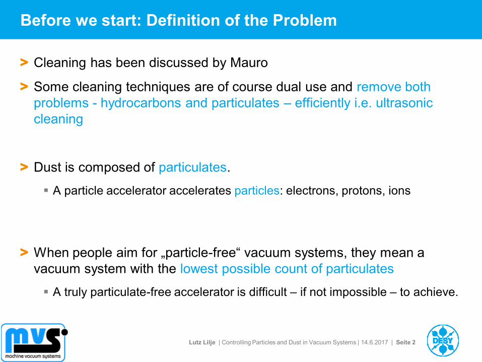
Before we start: Definition of the Problem
> Cleaning has been discussed by Mauro
> Some cleaning techniques are of course dual use and remove both
problems - hydrocarbons and particulates – efficiently i.e. ultrasonic
cleaning
> Dust is composed of particulates.
A particle accelerator accelerates particles: electrons, protons, ions
> When people aim for „particle-free“ vacuum systems, they mean a
vacuum system with the lowest possible count of particulates
A truly particulate-free accelerator is difficult – if not impossible – to achieve.
Lutz Lilje | Controlling Particles and Dust in Vacuum Systems | 14.6.2017 | Seite 3
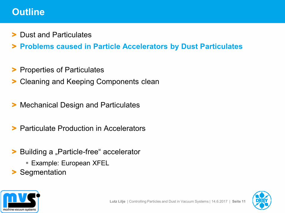
Outline
> Dust and Particulates
> Problems caused in Particle Accelerators by Dust Particulates
> Properties of Particulates
> Cleaning and Keeping Components clean
> Mechanical Design and Particulates
> Particulate Production in Accelerators
> Building a „Particle-free“ accelerator
Example: European XFEL
> Segmentation
Lutz Lilje | Controlling Particles and Dust in Vacuum Systems | 14.6.2017 | Seite 4
Outline
> Dust and Particulates
> Problems caused in Particle Accelerators by Dust Particulates
> Properties of Particulates
> Cleaning and Keeping Components clean
> Mechanical Design and Particulates
> Particulate Production in Accelerators
> Building a „Particle-free“ accelerator
Example: European XFEL
> Segmentation
Lutz Lilje | Controlling Particles and Dust in Vacuum Systems | 14.6.2017 | Seite 5
Dust and
Particulates
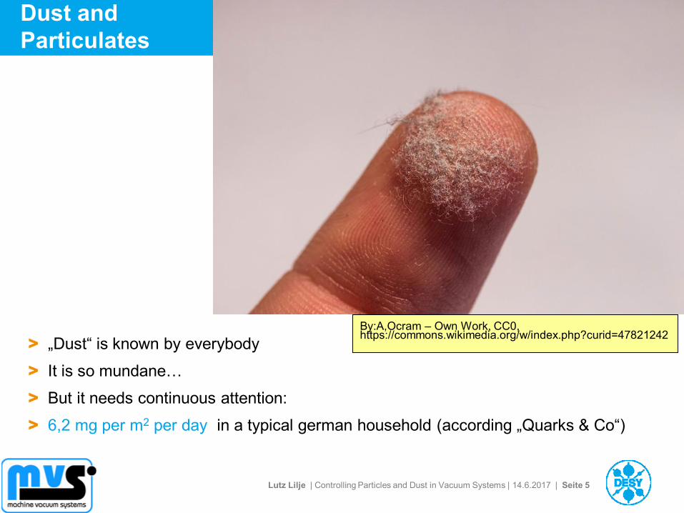
> „Dust“ is known by everybody
> It is so mundane…
> But it needs continuous attention:
> 6,2 mg per m2 per day in a typical german household (according „Quarks & Co“)
By:A,Ocram – Own Work, CC0, https://commons.wikimedia.org/w/index.php?curid=47821242
Lutz Lilje | Controlling Particles and Dust in Vacuum Systems | 14.6.2017 | Seite 6
More Dust
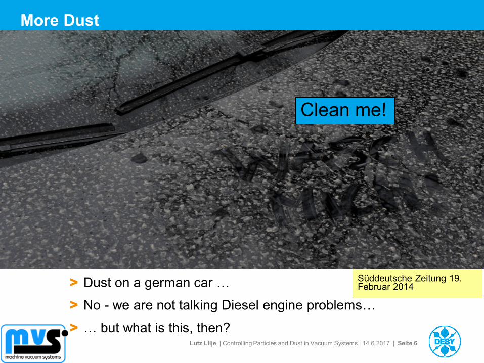
> Dust on a german car …
> No - we are not talking Diesel engine problems…
> … but what is this, then?
Süddeutsche Zeitung 19. Februar 2014
Clean me!
Lutz Lilje | Controlling Particles and Dust in Vacuum Systems | 14.6.2017 | Seite 7
A lot of Dust!
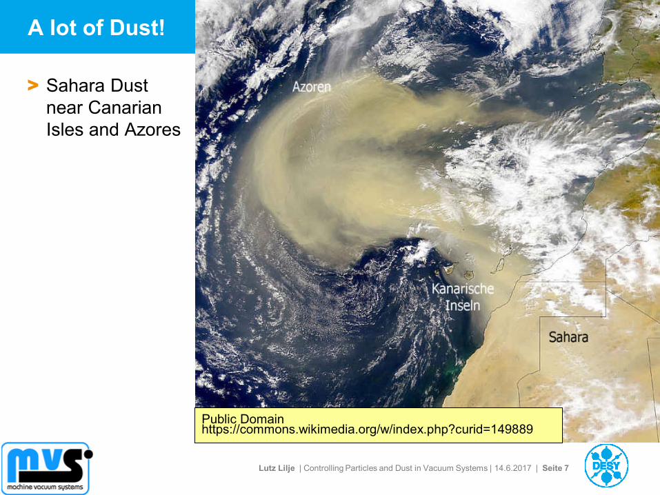
> Sahara Dust
near Canarian
Isles and Azores
Public Domain https://commons.wikimedia.org/w/index.php?curid=149889
Lutz Lilje | Controlling Particles and Dust in Vacuum Systems | 14.6.2017 | Seite 8
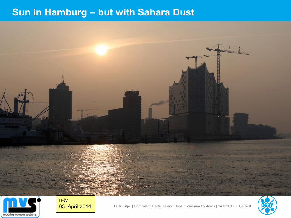
Sun in Hamburg – but with Sahara Dust
n-tv,
03. April 2014
Lutz Lilje | Controlling Particles and Dust in Vacuum Systems | 14.6.2017 | Seite 9
And for the Night Owls: Moon with Sahara Dust
W. Vollmann, Wien
Lutz Lilje | Controlling Particles and Dust in Vacuum Systems | 14.6.2017 | Seite 10
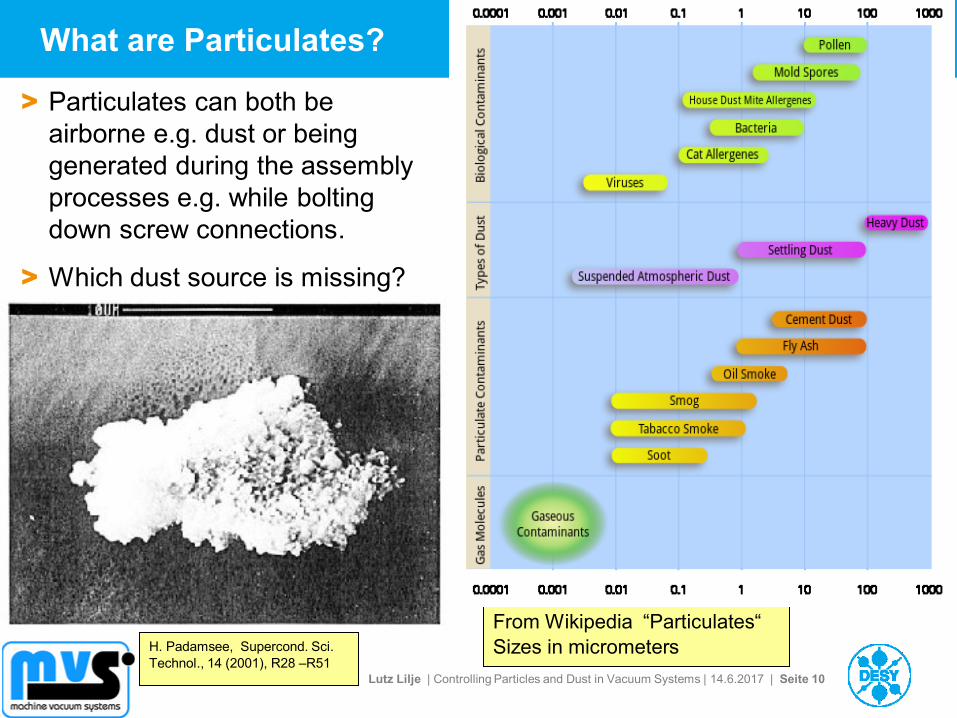
What are Particulates?
> Particulates can both be
airborne e.g. dust or being
generated during the assembly
processes e.g. while bolting
down screw connections.
> Which dust source is missing?
From Wikipedia “Particulates“
Sizes in micrometers H. Padamsee, Supercond. Sci.
Technol., 14 (2001), R28 –R51
Lutz Lilje | Controlling Particles and Dust in Vacuum Systems | 14.6.2017 | Seite 11
Outline
> Dust and Particulates
> Problems caused in Particle Accelerators by Dust Particulates
> Properties of Particulates
> Cleaning and Keeping Components clean
> Mechanical Design and Particulates
> Particulate Production in Accelerators
> Building a „Particle-free“ accelerator
Example: European XFEL
> Segmentation
Lutz Lilje | Controlling Particles and Dust in Vacuum Systems | 14.6.2017 | Seite 12
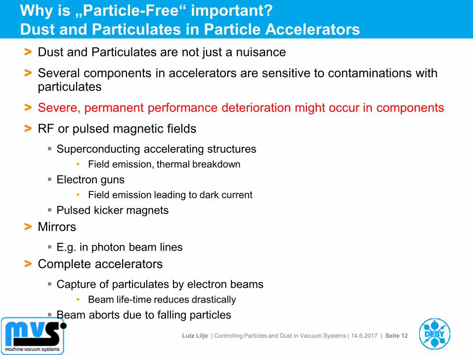
Why is „Particle-Free“ important?
Dust and Particulates in Particle Accelerators
> Dust and Particulates are not just a nuisance
> Several components in accelerators are sensitive to contaminations with particulates
> Severe, permanent performance deterioration might occur in components
> RF or pulsed magnetic fields
Superconducting accelerating structures
• Field emission, thermal breakdown
Electron guns
• Field emission leading to dark current
Pulsed kicker magnets
> Mirrors
E.g. in photon beam lines
> Complete accelerators
Capture of particulates by electron beams
• Beam life-time reduces drastically
Beam aborts due to falling particles
Lutz Lilje | Controlling Particles and Dust in Vacuum Systems | 14.6.2017 | Seite 13
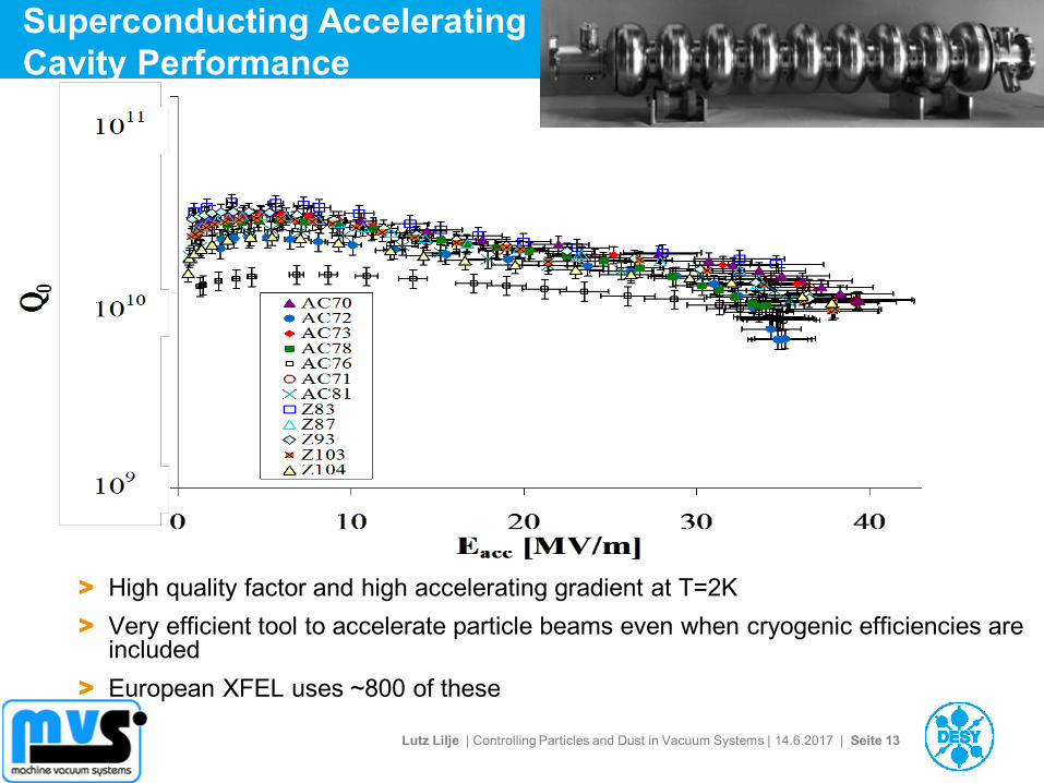
Superconducting Accelerating
Cavity Performance
> High quality factor and high accelerating gradient at T=2K
> Very efficient tool to accelerate particle beams even when cryogenic efficiencies are included
> European XFEL uses ~800 of these
Lutz Lilje | Controlling Particles and Dust in Vacuum Systems | 14.6.2017 | Seite 14
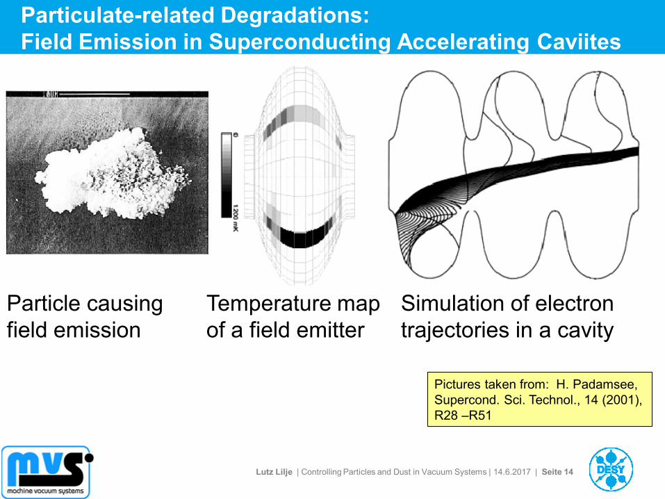
Particulate-related Degradations:
Field Emission in Superconducting Accelerating Caviites
Simulation of electron
trajectories in a cavity
Temperature map
of a field emitter
Particle causing
field emission
Pictures taken from: H. Padamsee,
Supercond. Sci. Technol., 14 (2001),
R28 –R51
Lutz Lilje | Controlling Particles and Dust in Vacuum Systems | 14.6.2017 | Seite 15
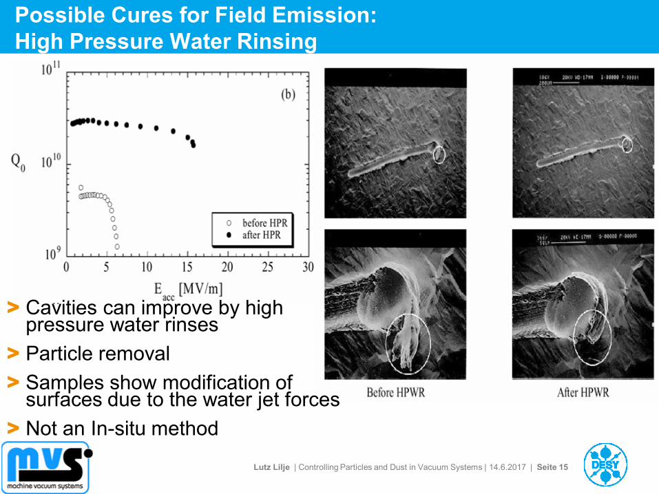
Possible Cures for Field Emission:
High Pressure Water Rinsing
> Cavities can improve by high pressure water rinses
> Particle removal
> Samples show modification of surfaces due to the water jet forces
> Not an In-situ method
Lutz Lilje | Controlling Particles and Dust in Vacuum Systems | 14.6.2017 | Seite 16
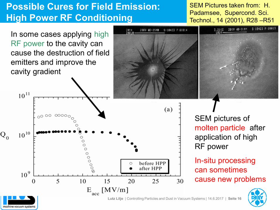
Possible Cures for Field Emission:
High Power RF Conditioning
In some cases applying high
RF power to the cavity can
cause the destruction of field
emitters and improve the
cavity gradient
SEM pictures of
molten particle after
application of high
RF power
In-situ processing
can sometimes
cause new problems
SEM Pictures taken from: H.
Padamsee, Supercond. Sci.
Technol., 14 (2001), R28 –R51
Lutz Lilje | Controlling Particles and Dust in Vacuum Systems | 14.6.2017 | Seite 17
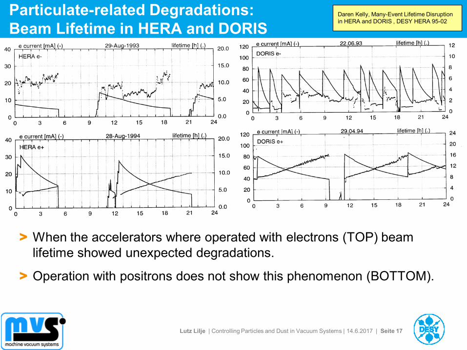
Particulate-related Degradations:
Beam Lifetime in HERA and DORIS
> When the accelerators where operated with electrons (TOP) beam
lifetime showed unexpected degradations.
> Operation with positrons does not show this phenomenon (BOTTOM).
Daren Kelly, Many-Event Lifetime Disruption
in HERA and DORIS , DESY HERA 95-02
Lutz Lilje | Controlling Particles and Dust in Vacuum Systems | 14.6.2017 | Seite 18
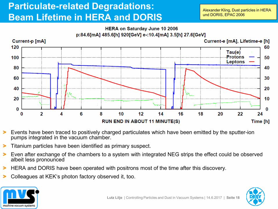
Particulate-related Degradations:
Beam Lifetime in HERA and DORIS
> Events have been traced to positively charged particulates which have been emitted by the sputter-ion pumps integrated in the vacuum chamber.
> Titanium particles have been identified as primary suspect.
> Even after exchange of the chambers to a system with integrated NEG strips the effect could be observed albeit less pronounced
> HERA and DORIS have been operated with positrons most of the time after this discovery.
> Colleagues at KEK‘s photon factory observed it, too.
Alexander Kling, Dust particles in HERA
und DORIS, EPAC 2006
Lutz Lilje | Controlling Particles and Dust in Vacuum Systems | 14.6.2017 | Seite 19
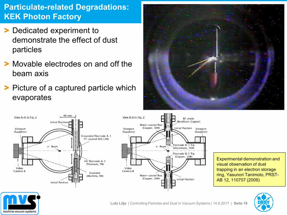
Particulate-related Degradations:
KEK Photon Factory
Experimental demonstration and
visual observation of dust
trapping in an electron storage
ring, Yasunori Tanimoto, PRST-
AB 12, 110707 (2009)
> Dedicated experiment to
demonstrate the effect of dust
particles
> Movable electrodes on and off the
beam axis
> Picture of a captured particle which
evaporates
Lutz Lilje | Controlling Particles and Dust in Vacuum Systems | 14.6.2017 | Seite 20
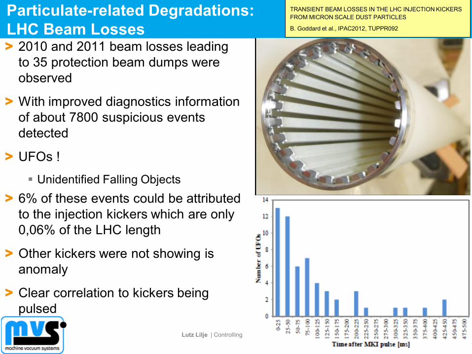
Particulate-related Degradations:
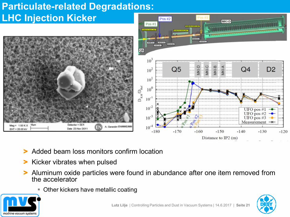
LHC Beam Losses > 2010 and 2011 beam losses leading
to 35 protection beam dumps were
observed
> With improved diagnostics information
of about 7800 suspicious events
detected
> UFOs !
Unidentified Falling Objects
> 6% of these events could be attributed
to the injection kickers which are only
0,06% of the LHC length
> Other kickers were not showing is
anomaly
> Clear correlation to kickers being
pulsed
TRANSIENT BEAM LOSSES IN THE LHC INJECTION KICKERS
FROM MICRON SCALE DUST PARTICLES
B. Goddard et al., IPAC2012, TUPPR092
Lutz Lilje | Controlling Particles and Dust in Vacuum Systems | 14.6.2017 | Seite 21
Particulate-related Degradations:
LHC Injection Kicker
> Added beam loss monitors confirm location
> Kicker vibrates when pulsed
> Aluminum oxide particles were found in abundance after one item removed from the accelerator
Other kickers have metallic coating
Lutz Lilje | Controlling Particles and Dust in Vacuum Systems | 14.6.2017 | Seite 22
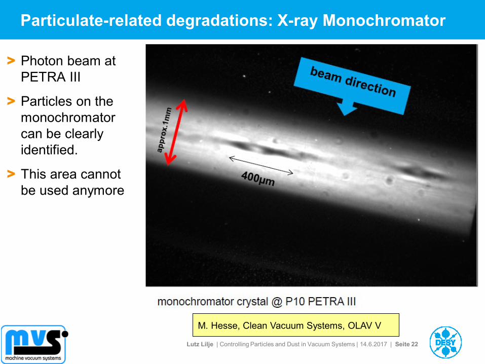
Particulate-related degradations: X-ray Monochromator
> Photon beam at
PETRA III
> Particles on the
monochromator
can be clearly
identified.
> This area cannot
be used anymore
M. Hesse, Clean Vacuum Systems, OLAV V
Lutz Lilje | Controlling Particles and Dust in Vacuum Systems | 14.6.2017 | Seite 23
Outline
> Dust and Particulates
> Problems caused in Particle Accelerators by Dust Particulates
> Properties of Particulates
> Cleaning and Keeping Components clean
> Mechanical Design and Particulates
> Particulate Production in Accelerators
> Building a „Particle-free“ accelerator
Example: European XFEL
> Segmentation
Lutz Lilje | Controlling Particles and Dust in Vacuum Systems | 14.6.2017 | Seite 24
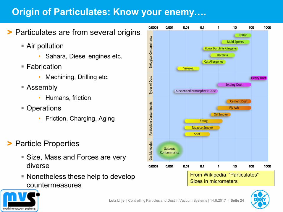
Origin of Particulates: Know your enemy….
> Particulates are from several origins
Air pollution
• Sahara, Diesel engines etc.
Fabrication
• Machining, Drilling etc.
Assembly
• Humans, friction
Operations
• Friction, Charging, Aging
> Particle Properties
Size, Mass and Forces are very
diverse
Nonetheless these help to develop
countermeasures
From Wikipedia “Particulates“
Sizes in micrometers
Lutz Lilje | Controlling Particles and Dust in Vacuum Systems | 14.6.2017 | Seite 25
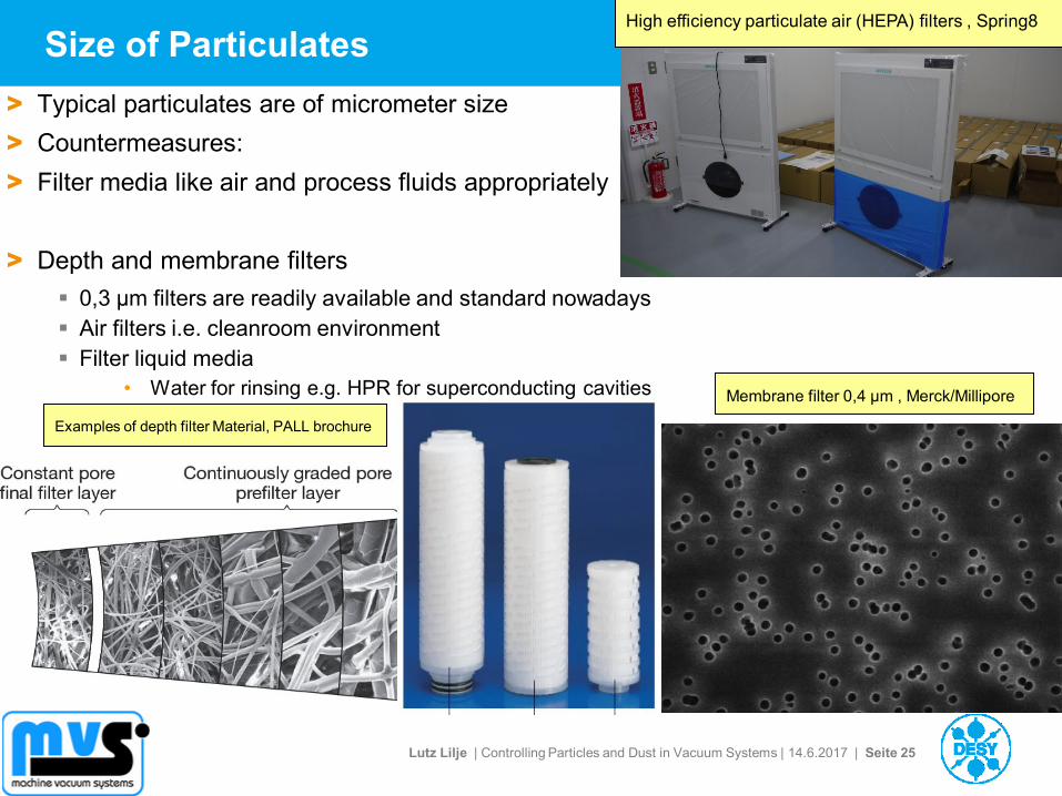
Examples of depth filter Material, PALL brochure
Size of Particulates High efficiency particulate air (HEPA) filters , Spring8
> Typical particulates are of micrometer size
> Countermeasures:
> Filter media like air and process fluids appropriately
> Depth and membrane filters
0,3 µm filters are readily available and standard nowadays
Air filters i.e. cleanroom environment
Filter liquid media
• Water for rinsing e.g. HPR for superconducting cavities Membrane filter 0,4 µm , Merck/Millipore
Lutz Lilje | Controlling Particles and Dust in Vacuum Systems | 14.6.2017 | Seite 26
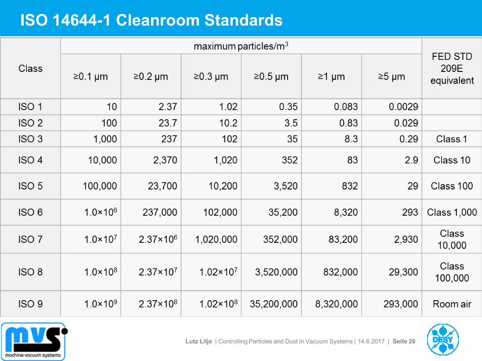
ISO 14644-1 Cleanroom Standards
27
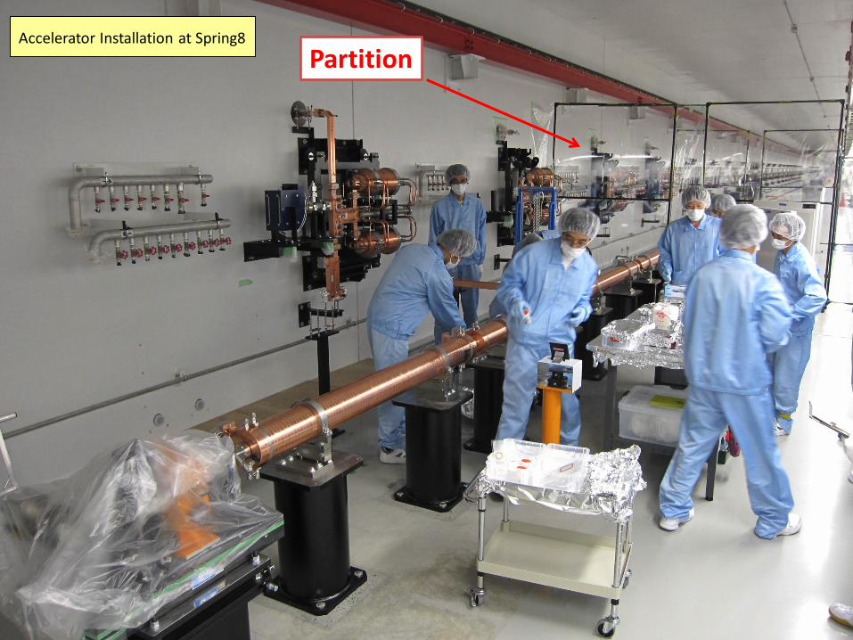
Partition Accelerator Installation at Spring8
28
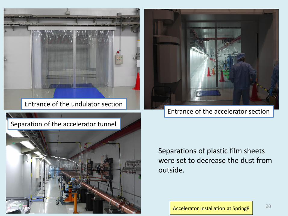
Separations of plastic film sheets were set to decrease the dust from outside.
Entrance of the accelerator section Entrance of the undulator section
Separation of the accelerator tunnel
Accelerator Installation at Spring8
29
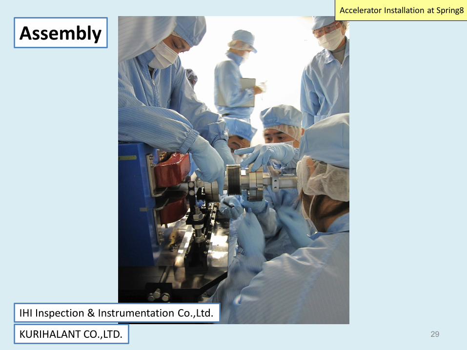
Assembly
IHI Inspection & Instrumentation Co.,Ltd.
KURIHALANT CO.,LTD.
Accelerator Installation at Spring8
Lutz Lilje | Controlling Particles and Dust in Vacuum Systems | 14.6.2017 | Seite 30
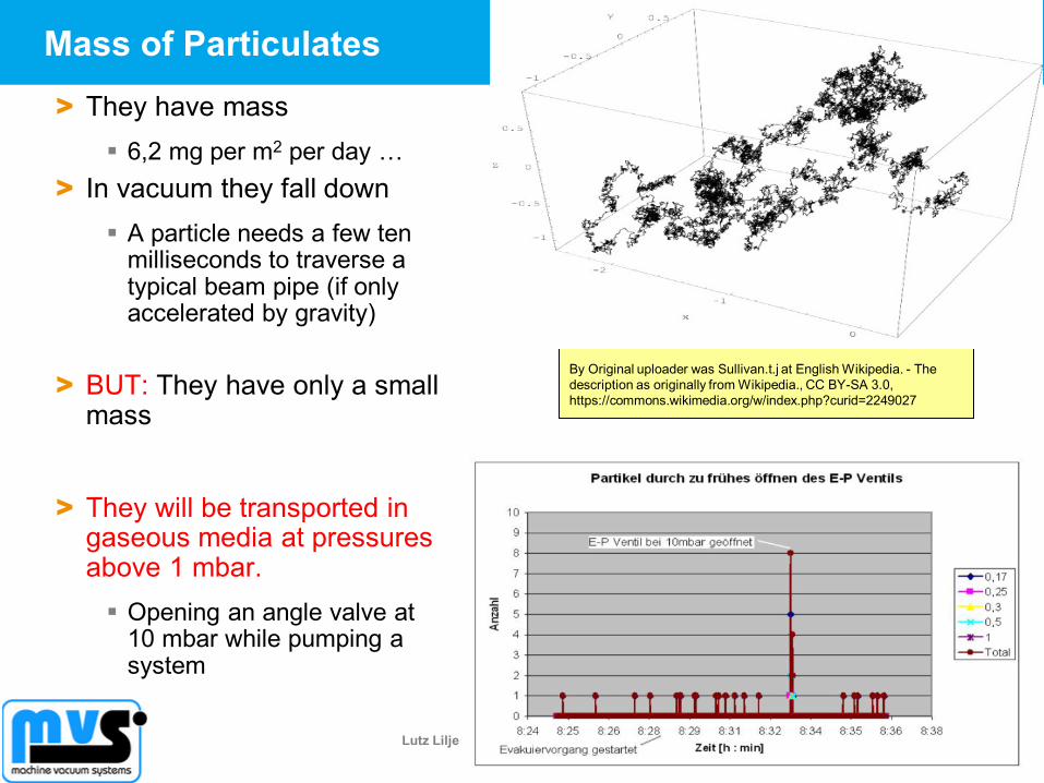
Mass of Particulates
> They have mass
6,2 mg per m2 per day …
> In vacuum they fall down
A particle needs a few ten milliseconds to traverse a typical beam pipe (if only accelerated by gravity)
> BUT: They have only a small mass
> They will be transported in gaseous media at pressures above 1 mbar.
Opening an angle valve at 10 mbar while pumping a system
By Original uploader was Sullivan.t.j at English Wikipedia. - The
description as originally from Wikipedia., CC BY-SA 3.0,
https://commons.wikimedia.org/w/index.php?curid=2249027
Lutz Lilje | Controlling Particles and Dust in Vacuum Systems | 14.6.2017 | Seite 31
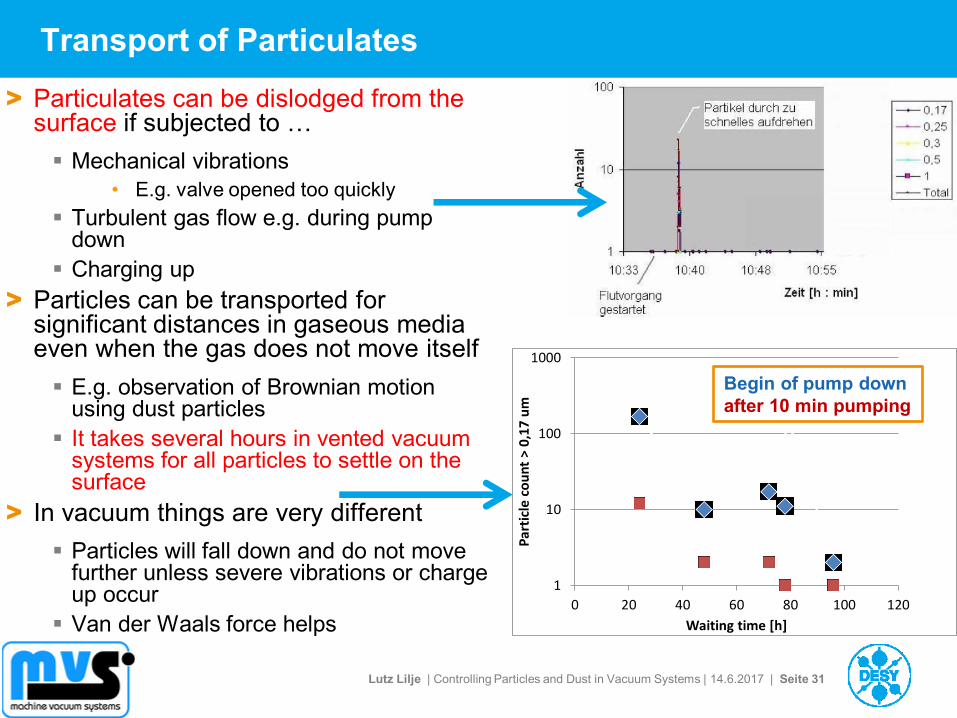
Transport of Particulates
> Particulates can be dislodged from the surface if subjected to …
Mechanical vibrations
• E.g. valve opened too quickly
Turbulent gas flow e.g. during pump down
Charging up
> Particles can be transported for significant distances in gaseous media even when the gas does not move itself
E.g. observation of Brownian motion using dust particles
It takes several hours in vented vacuum systems for all particles to settle on the surface
> In vacuum things are very different
Particles will fall down and do not move further unless severe vibrations or charge up occur
Van der Waals force helps
1
10
100
1000
0 20 40 60 80 100 120
Par
ticl
e co
un
t >
0,1
7 u
m
Waiting time [h]
Begin of pump down
after 10 min pumping
Lutz Lilje | Controlling Particles and Dust in Vacuum Systems | 14.6.2017 | Seite 32
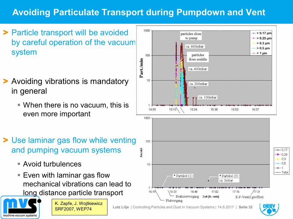
Avoiding Particulate Transport during Pumpdown and Vent
> Particle transport will be avoided
by careful operation of the vacuum
system
> Avoiding vibrations is mandatory
in general
When there is no vacuum, this is
even more important
> Use laminar gas flow while venting
and pumping vacuum systems
Avoid turbulences
Even with laminar gas flow
mechanical vibrations can lead to
long distance particle transport
K. Zapfe, J. Wojtkiewicz
SRF2007, WEP74
Lutz Lilje | Controlling Particles and Dust in Vacuum Systems | 14.6.2017 | Seite 33
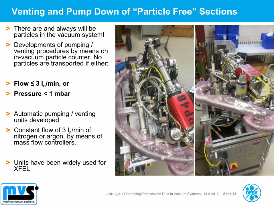
Venting and Pump Down of “Particle Free” Sections
> There are and always will be particles in the vacuum system!
> Developments of pumping / venting procedures by means on in-vacuum particle counter. No particles are transported if either:
> Flow ≤ 3 ln/min, or
> Pressure < 1 mbar
> Automatic pumping / venting units developed
> Constant flow of 3 ln/min of nitrogen or argon, by means of mass flow controllers.
> Units have been widely used for XFEL
Lutz Lilje | Controlling Particles and Dust in Vacuum Systems | 14.6.2017 | Seite 34
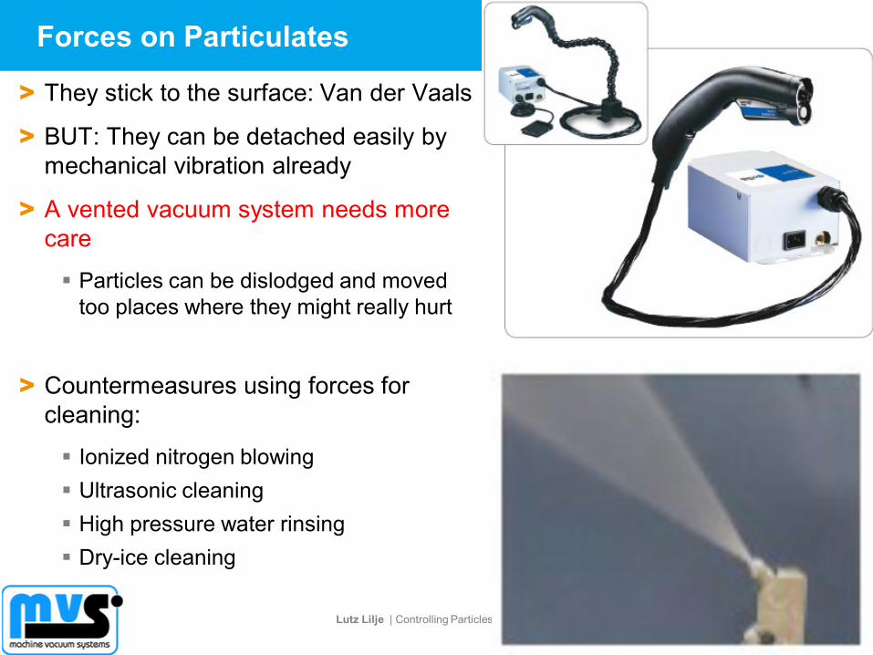
Forces on Particulates
> They stick to the surface: Van der Vaals
> BUT: They can be detached easily by
mechanical vibration already
> A vented vacuum system needs more
care
Particles can be dislodged and moved
too places where they might really hurt
> Countermeasures using forces for
cleaning:
Ionized nitrogen blowing
Ultrasonic cleaning
High pressure water rinsing
Dry-ice cleaning
Lutz Lilje | Controlling Particles and Dust in Vacuum Systems | 14.6.2017 | Seite 35
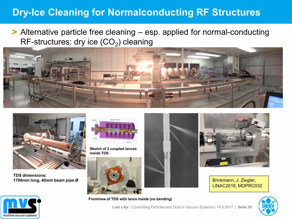
Dry-Ice Cleaning for Normalconducting RF Structures
> Alternative particle free cleaning – esp. applied for normal-conducting
RF-structures: dry ice (CO2) cleaning
Brinkmann, J. Ziegler,
LINAC2016, MOPRC032
TDS dimensions:
1700mm long, 40mm beam pipe Ø
Sketch of 2 coupled lances
inside TDS
Frontview of TDS with lance inside (no bending)
Lutz Lilje | Controlling Particles and Dust in Vacuum Systems | 14.6.2017 | Seite 36
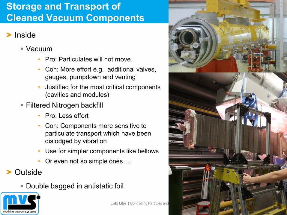
Storage and Transport of
Cleaned Vacuum Components
> Inside
Vacuum
• Pro: Particulates will not move
• Con: More effort e.g. additional valves,
gauges, pumpdown and venting
• Justified for the most critical components
(cavities and modules)
Filtered Nitrogen backfill
• Pro: Less effort
• Con: Components more sensitive to
particulate transport which have been
dislodged by vibration
• Use for simpler components like bellows
• Or even not so simple ones….
> Outside
Double bagged in antistatic foil

Lutz Lilje | Controlling Particles and Dust in Vacuum Systems | 14.6.2017 | Seite 37
Outline
> Dust and Particulates
> Problems caused in Particle Accelerators by Dust Particulates
> Properties of Particulates
> Cleaning and Keeping Components clean
> Mechanical Design and Particulates
> Particulate Production in Accelerators
> Building a „Particle-free“ accelerator
Example: European XFEL
> Segmentation
Lutz Lilje | Controlling Particles and Dust in Vacuum Systems | 14.6.2017 | Seite 38
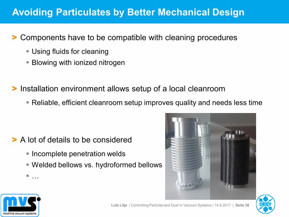
Avoiding Particulates by Better Mechanical Design
> Components have to be compatible with cleaning procedures
Using fluids for cleaning
Blowing with ionized nitrogen
> Installation environment allows setup of a local cleanroom
Reliable, efficient cleanroom setup improves quality and needs less time
> A lot of details to be considered
Incomplete penetration welds
Welded bellows vs. hydroformed bellows
…
Lutz Lilje | Controlling Particles and Dust in Vacuum Systems | 14.6.2017 | Seite 39
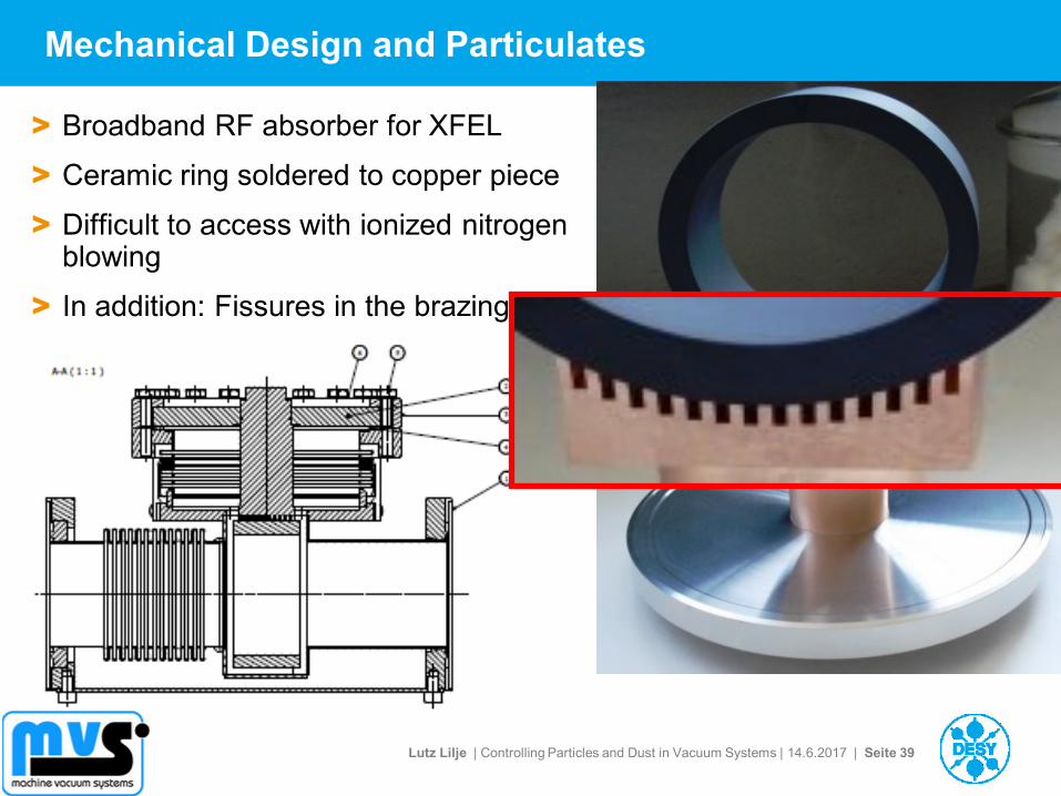
Mechanical Design and Particulates
> Broadband RF absorber for XFEL
> Ceramic ring soldered to copper piece
> Difficult to access with ionized nitrogen blowing
> In addition: Fissures in the brazing
Lutz Lilje | Controlling Particles and Dust in Vacuum Systems | 14.6.2017 | Seite 40
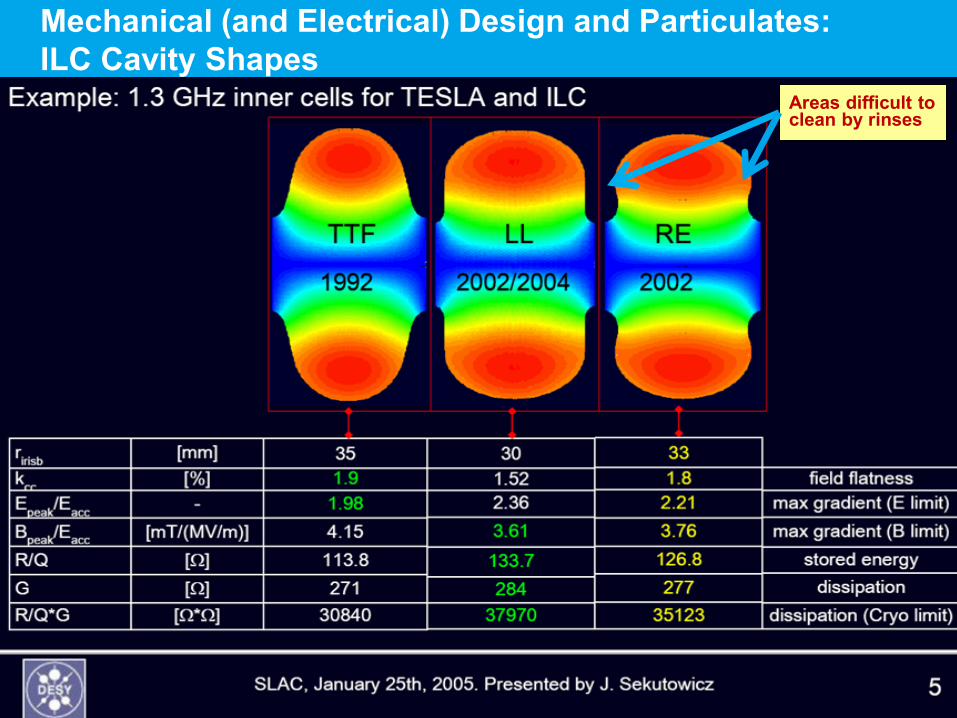
Mechanical (and Electrical) Design and Particulates:
ILC Cavity Shapes
Areas difficult to clean by rinses
Lutz Lilje | Controlling Particles and Dust in Vacuum Systems | 14.6.2017 | Seite 41
Outline
> Dust and Particulates
> Problems caused in Particle Accelerators by Dust Particulates
> Properties of Particulates
> Cleaning and Keeping Components clean
> Mechanical Design and Particulates
> Particulate Production in Accelerators
> Building a „Particle-free“ accelerator
Example: European XFEL
> Segmentation
Lutz Lilje | Controlling Particles and Dust in Vacuum Systems | 14.6.2017 | Seite 42
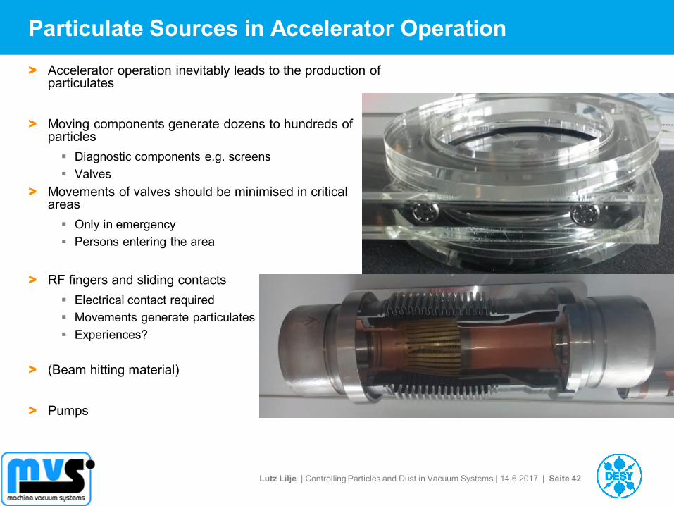
Particulate Sources in Accelerator Operation
> Accelerator operation inevitably leads to the production of particulates
> Moving components generate dozens to hundreds of particles
Diagnostic components e.g. screens
Valves
> Movements of valves should be minimised in critical areas
Only in emergency
Persons entering the area
> RF fingers and sliding contacts
Electrical contact required
Movements generate particulates
Experiences?
> (Beam hitting material)
> Pumps
Lutz Lilje | Controlling Particles and Dust in Vacuum Systems | 14.6.2017 | Seite 43
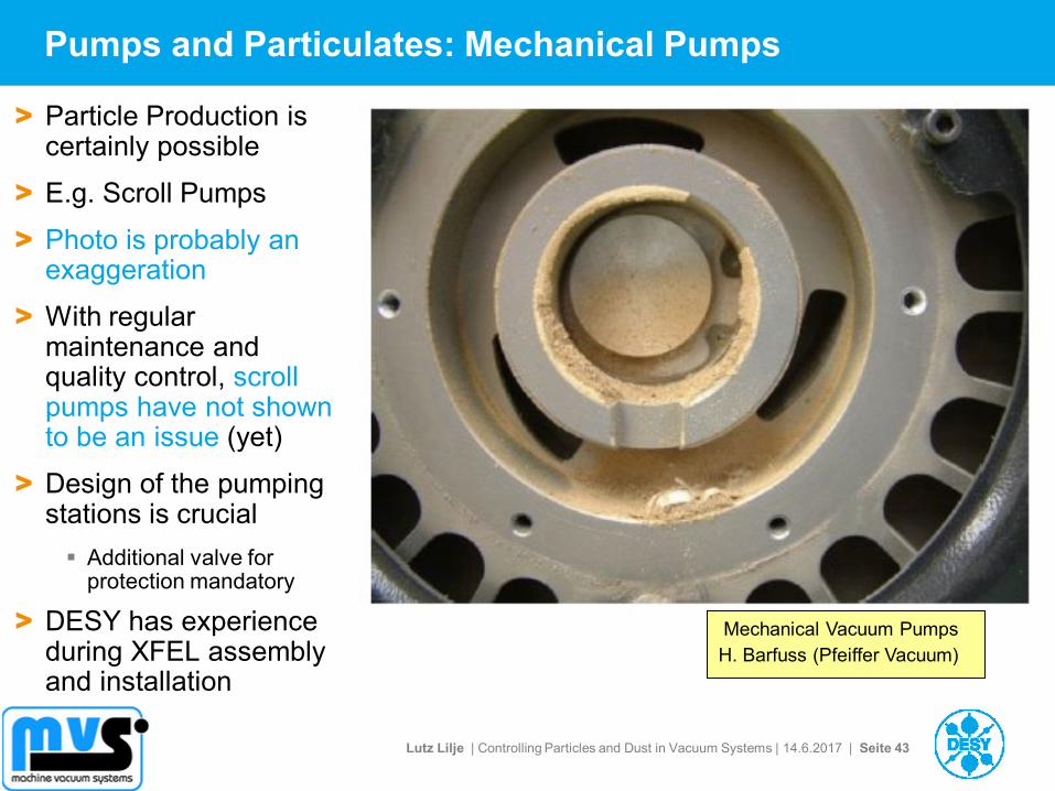
Pumps and Particulates: Mechanical Pumps
> Particle Production is certainly possible
> E.g. Scroll Pumps
> Photo is probably an exaggeration
> With regular maintenance and quality control, scroll pumps have not shown to be an issue (yet)
> Design of the pumping stations is crucial
Additional valve for protection mandatory
> DESY has experience during XFEL assembly and installation
Mechanical Vacuum Pumps
H. Barfuss (Pfeiffer Vacuum)
Lutz Lilje | Controlling Particles and Dust in Vacuum Systems | 14.6.2017 | Seite 44
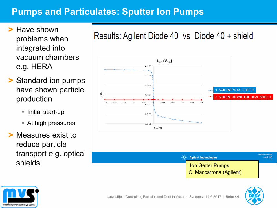
Pumps and Particulates: Sputter Ion Pumps
> Have shown
problems when
integrated into
vacuum chambers
e.g. HERA
> Standard ion pumps
have shown particle
production
Initial start-up
At high pressures
> Measures exist to
reduce particle
transport e.g. optical
shields Ion Getter Pumps
C. Maccarrone (Agilent)
Lutz Lilje | Controlling Particles and Dust in Vacuum Systems | 14.6.2017 | Seite 45
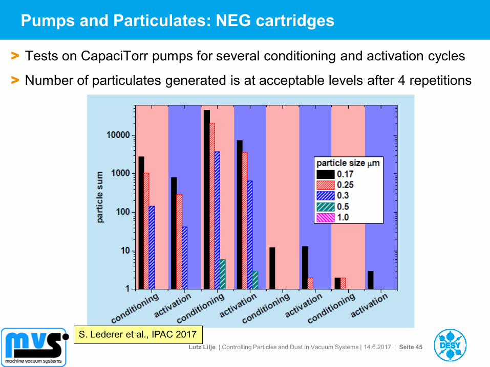
Pumps and Particulates: NEG cartridges
> Tests on CapaciTorr pumps for several conditioning and activation cycles
> Number of particulates generated is at acceptable levels after 4 repetitions
S. Lederer et al., IPAC 2017
Lutz Lilje | Controlling Particles and Dust in Vacuum Systems | 14.6.2017 | Seite 46
Outline
> Dust and Particulates
> Problems caused in Particle Accelerators by Dust Particulates
> Properties of Particulates
> Cleaning and Keeping Components clean
> Mechanical Design and Particulates
> Particulate Production in Accelerators
> Building a „Particle-free“ accelerator
Example: European XFEL
> Segmentation
Lutz Lilje | Controlling Particles and Dust in Vacuum Systems | 14.6.2017 | Seite 47
Basic Rules for a „Particle-free“ Accelerator
> Avoid particulates at every stage and include it in the mechanical design
> Remove particulates at every stage possible
> Do not produce particulates especially during installation and operation
> Never transport particulates
> … be prepared for reasonable compromises!
Lutz Lilje | Controlling Particles and Dust in Vacuum Systems | 14.6.2017 | Seite 48
How to built an „Particle-free“ Accelerator?
> Layout and segmentation
> Design and manufacturing
> Cleaning of components is mandatory
> Handling of components in clean environments is necessary
Clean rooms
> Even after clean assembly particulates can be produced in the system
Movement of valves, fast shutters, view screens, sliding contacts
> A macroscopic vacuum system of several kilometers will not be completely free of particulates – even when maximum care is being taken.
Transport of these particulates must be avoided
> Procedures during operation have to reflect this
Controlled slow venting with filtered gas
Lutz Lilje | Controlling Particles and Dust in Vacuum Systems | 14.6.2017 | Seite 49
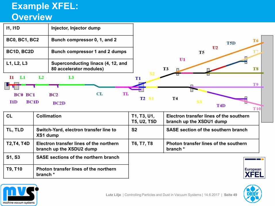
Example XFEL:
Overview
CL Collimation T1, T3, U1,
T5, U2, T5D
Electron transfer lines of the southern
branch up the XSDU1 dump
TL, TLD Switch-Yard, electron transfer line to
XS1 dump
S2 SASE section of the southern branch
T2,T4, T4D Electron transfer lines of the northern
branch up the XSDU2 dump
T6, T7, T8 Photon transfer lines of the southern
branch *
S1, S3 SASE sections of the northern branch
T9, T10 Photon transfer lines of the northern
branch *
I1, I1D Injector, Injector dump
BC0, BC1, BC2 Bunch compressor 0, 1, and 2
BC1D, BC2D Bunch compressor 1 and 2 dumps
L1, L2, L3 Superconducting linacs (4, 12, and
80 accelerator modules)
Lutz Lilje | Controlling Particles and Dust in Vacuum Systems | 14.6.2017 | Seite 50
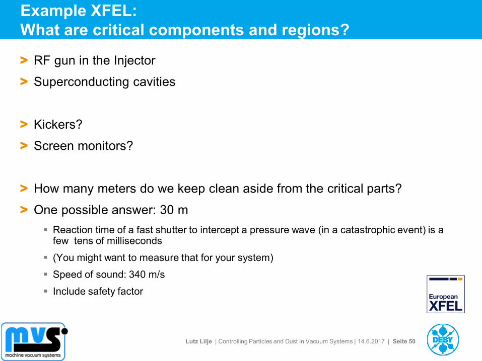
Example XFEL:
What are critical components and regions?
> RF gun in the Injector
> Superconducting cavities
> Kickers?
> Screen monitors?
> How many meters do we keep clean aside from the critical parts?
> One possible answer: 30 m
Reaction time of a fast shutter to intercept a pressure wave (in a catastrophic event) is a few tens of milliseconds
(You might want to measure that for your system)
Speed of sound: 340 m/s
Include safety factor
Lutz Lilje | Controlling Particles and Dust in Vacuum Systems | 14.6.2017 | Seite 52
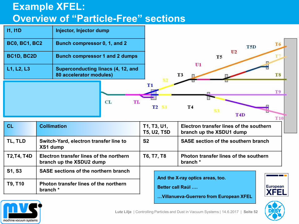
Example XFEL:
Overview of “Particle-Free” sections
CL Collimation T1, T3, U1,
T5, U2, T5D
Electron transfer lines of the southern
branch up the XSDU1 dump
TL, TLD Switch-Yard, electron transfer line to
XS1 dump
S2 SASE section of the southern branch
T2,T4, T4D Electron transfer lines of the northern
branch up the XSDU2 dump
T6, T7, T8 Photon transfer lines of the southern
branch *
S1, S3 SASE sections of the northern branch
T9, T10 Photon transfer lines of the northern
branch *
I1, I1D Injector, Injector dump
BC0, BC1, BC2 Bunch compressor 0, 1, and 2
BC1D, BC2D Bunch compressor 1 and 2 dumps
L1, L2, L3 Superconducting linacs (4, 12, and
80 accelerator modules)
And the X-ray optics areas, too.
Better call Raúl ….
…Villanueva-Guerrero from European XFEL
Lutz Lilje | Controlling Particles and Dust in Vacuum Systems | 14.6.2017 | Seite 53
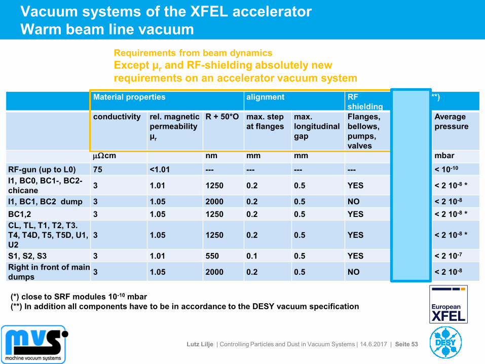
Vacuum systems of the XFEL accelerator
Warm beam line vacuum
Material properties alignment RF
shielding
Vacuum (**)
conductivity rel. magnetic
permeability
μr
R + 50*O max. step
at flanges
max.
longitudinal
gap
Flanges,
bellows,
pumps,
valves
Particle
free
Average
pressure
mWcm nm mm mm mbar
RF-gun (up to L0) 75 <1.01 --- --- --- --- ISO 5 < 10-10
I1, BC0, BC1-, BC2-
chicane 3 1.01 1250 0.2 0.5 YES ISO 5 < 2 10-8 *
I1, BC1, BC2 dump 3 1.05 2000 0.2 0.5 NO ISO 5 < 2 10-8
BC1,2 3 1.05 1250 0.2 0.5 YES ISO 5 < 2 10-8 *
CL, TL, T1, T2, T3.
T4, T4D, T5, T5D, U1,
U2
3 1.05 1250 0.2 0.5 YES NO < 2 10-8 *
S1, S2, S3 3 1.01 550 0.1 0.5 YES NO < 2 10-7
Right in front of main
dumps 3 1.05 2000 0.2 0.5 NO NO < 2 10-8
(*) close to SRF modules 10-10 mbar
(**) In addition all components have to be in accordance to the DESY vacuum specification
Requirements from beam dynamics
Except μr and RF-shielding absolutely new
requirements on an accelerator vacuum system
Lutz Lilje | Controlling Particles and Dust in Vacuum Systems | 14.6.2017 | Seite 54
Outline
> Dust and Particulates
> Problems caused in Particle Accelerators by Dust Particulates
> Properties of Particulates
> Cleaning and Keeping Components clean
> Mechanical Design and Particulates
> Particulate Production in Accelerators
> Building a „Particle-free“ accelerator
Example: European XFEL
> Segmentation
Lutz Lilje | Controlling Particles and Dust in Vacuum Systems | 14.6.2017 | Seite 55
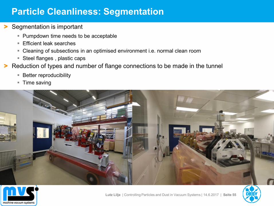
Particle Cleanliness: Segmentation
> Segmentation is important
Pumpdown time needs to be acceptable
Efficient leak searches
Cleaning of subsections in an optimised environment i.e. normal clean room
Steel flanges , plastic caps
> Reduction of types and number of flange connections to be made in the tunnel
Better reproducibility
Time saving
Lutz Lilje | Controlling Particles and Dust in Vacuum Systems | 14.6.2017 | Seite 56
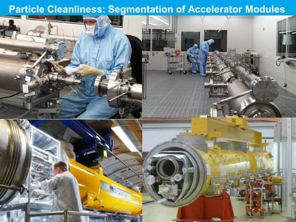
Particle Cleanliness: Segmentation of Accelerator Modules
Lutz Lilje | Controlling Particles and Dust in Vacuum Systems | 14.6.2017 | Seite 57
Outline
> Dust and Particulates
> Problems caused in Particle Accelerators by Dust Particulates
> Properties of Particulates
> Cleaning and Keeping Components clean
> Mechanical Design and Particulates
> Particulate Production in Accelerators
> Building a „Particle-free“ accelerator
Example: European XFEL
> Segmentation
Lutz Lilje | Controlling Particles and Dust in Vacuum Systems | 14.6.2017 | Seite 58
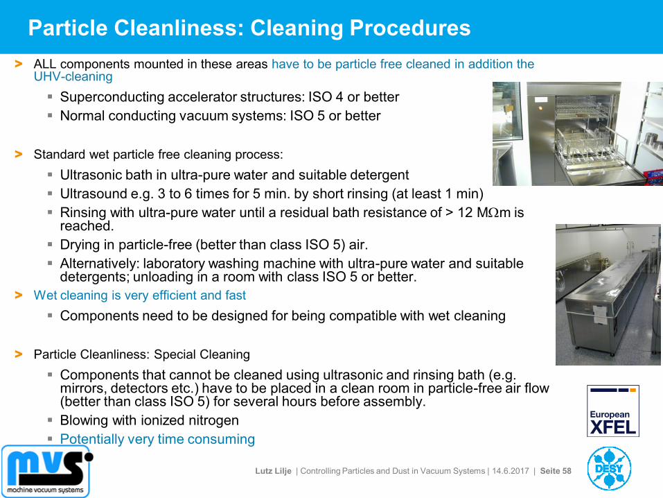
Particle Cleanliness: Cleaning Procedures
> ALL components mounted in these areas have to be particle free cleaned in addition the UHV-cleaning
Superconducting accelerator structures: ISO 4 or better
Normal conducting vacuum systems: ISO 5 or better
> Standard wet particle free cleaning process:
Ultrasonic bath in ultra-pure water and suitable detergent
Ultrasound e.g. 3 to 6 times for 5 min. by short rinsing (at least 1 min)
Rinsing with ultra-pure water until a residual bath resistance of > 12 MWm is reached.
Drying in particle-free (better than class ISO 5) air.
Alternatively: laboratory washing machine with ultra-pure water and suitable detergents; unloading in a room with class ISO 5 or better.
> Wet cleaning is very efficient and fast
Components need to be designed for being compatible with wet cleaning
> Particle Cleanliness: Special Cleaning
Components that cannot be cleaned using ultrasonic and rinsing bath (e.g. mirrors, detectors etc.) have to be placed in a clean room in particle-free air flow (better than class ISO 5) for several hours before assembly.
Blowing with ionized nitrogen
Potentially very time consuming
Lutz Lilje | Controlling Particles and Dust in Vacuum Systems | 14.6.2017 | Seite 59
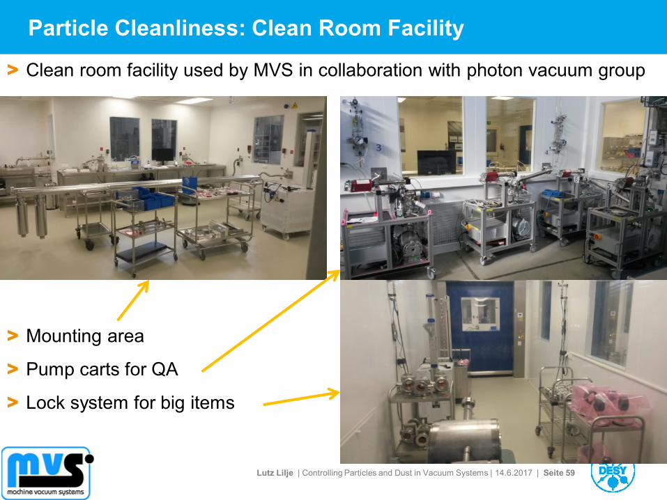
Particle Cleanliness: Clean Room Facility
> Mounting area
> Pump carts for QA
> Lock system for big items
> Clean room facility used by MVS in collaboration with photon vacuum group
Lutz Lilje | Controlling Particles and Dust in Vacuum Systems | 14.6.2017 | Seite 60
Particle Cleanliness: Quality Checks
> The absence of particles has to be controlled in a clean room class ISO
5 or better. Therefore the components will be cleaned with particle free
ionized nitrogen. After 5 minutes using a gas throughput of 28 l/min
there should be at maximum 10 particles/minute ≥ 0.3 mm be detected.
> The assembly of components and the joining of vacuum parts has to be
performed in a environment according to the specified clean room
class. Control with standard particle counters.
> Gaps in flange connections need to be masked on the outside with
clean room compatible adhesive tape to avoid particle contamination in
the flange area.
> (Standard vacuum checks: RGA and leak check)
Lutz Lilje | Controlling Particles and Dust in Vacuum Systems | 14.6.2017 | Seite 61
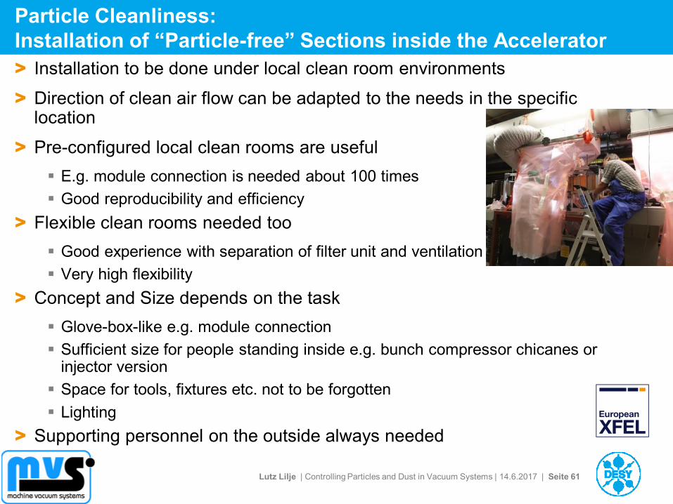
Particle Cleanliness:
Installation of “Particle-free” Sections inside the Accelerator
> Installation to be done under local clean room environments
> Direction of clean air flow can be adapted to the needs in the specific location
> Pre-configured local clean rooms are useful
E.g. module connection is needed about 100 times
Good reproducibility and efficiency
> Flexible clean rooms needed too
Good experience with separation of filter unit and ventilation
Very high flexibility
> Concept and Size depends on the task
Glove-box-like e.g. module connection
Sufficient size for people standing inside e.g. bunch compressor chicanes or injector version
Space for tools, fixtures etc. not to be forgotten
Lighting
> Supporting personnel on the outside always needed
Lutz Lilje | Controlling Particles and Dust in Vacuum Systems | 14.6.2017 | Seite 62
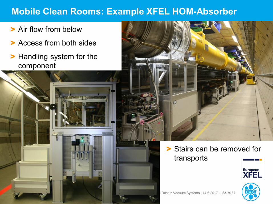
Mobile Clean Rooms: Example XFEL HOM-Absorber
> Air flow from below
> Access from both sides
> Handling system for the
component
> Stairs can be removed for
transports
Lutz Lilje | Controlling Particles and Dust in Vacuum Systems | 14.6.2017 | Seite 63
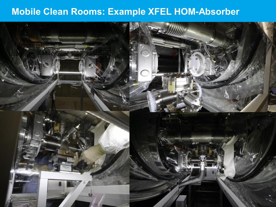
Mobile Clean Rooms: Example XFEL HOM-Absorber
Lutz Lilje | Controlling Particles and Dust in Vacuum Systems | 14.6.2017 | Seite 64
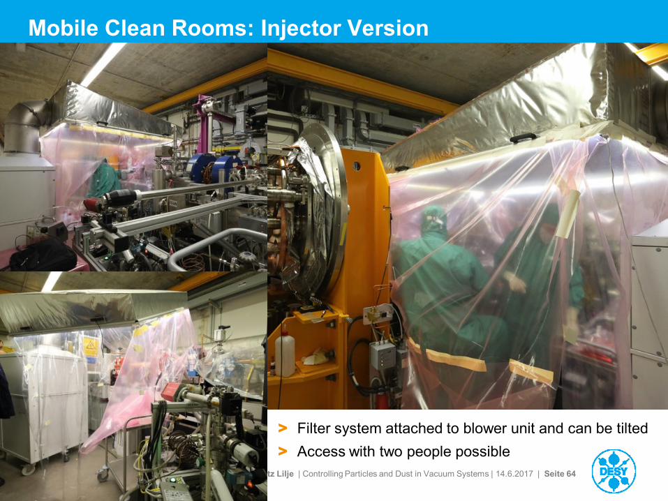
Mobile Clean Rooms: Injector Version
> Filter system attached to blower unit and can be tilted
> Access with two people possible
Lutz Lilje | Controlling Particles and Dust in Vacuum Systems | 14.6.2017 | Seite 65
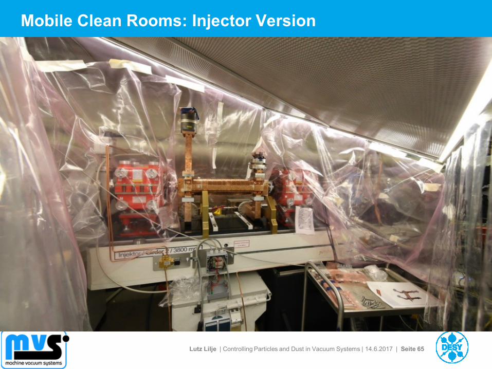
Mobile Clean Rooms: Injector Version
Lutz Lilje | Controlling Particles and Dust in Vacuum Systems | 14.6.2017 | Seite 66
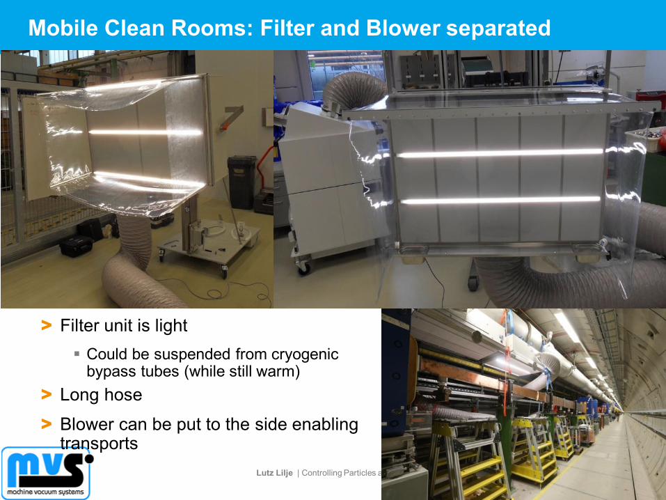
Mobile Clean Rooms: Filter and Blower separated
> Filter unit is light
Could be suspended from cryogenic bypass tubes (while still warm)
> Long hose
> Blower can be put to the side enabling transports
Lutz Lilje | Controlling Particles and Dust in Vacuum Systems | 14.6.2017 | Seite 67
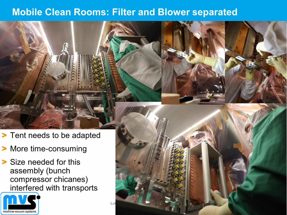
Mobile Clean Rooms: Filter and Blower separated
> Tent needs to be adapted
> More time-consuming
> Size needed for this assembly (bunch compressor chicanes) interfered with transports
Lutz Lilje | Controlling Particles and Dust in Vacuum Systems | 14.6.2017 | Seite 68
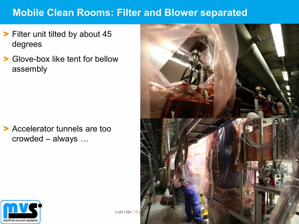
Mobile Clean Rooms: Filter and Blower separated
> Filter unit tilted by about 45
degrees
> Glove-box like tent for bellow
assembly
> Accelerator tunnels are too
crowded – always …
Lutz Lilje | Controlling Particles and Dust in Vacuum Systems | 14.6.2017 | Seite 69
XFEL „Particle-free“ Highlights in Numbers
> 1 RF Gun including cathode handling system
Very delicate components, very little space, very demanding requirements
> 38 girders with 5 m each
More than 500 different pieces
Tubes, pumps, compensators, diagnostics incl. transverse deflecting structure,
> Laser heater chicane
> 3 Bunch Compressor Chicanes
Long chambers
Large flanges
> 6 pressure stages at warm cold transition
> 3 dump lines
> 60 m warm beam line at the end of the cold linac as a buffer zone
> For the 100 accelerator modules
200 all metal date valves
800 cavity and 800 coupler bellows
200 coupler pump lines with TSP, sputter ion pump
100 HOM Absorbers
Plus testing, installation etc.
> More than 1,5 km of vacuum chambers have been cleaned (without the cavities)
Lutz Lilje | Controlling Particles and Dust in Vacuum Systems | 14.6.2017 | Seite 70
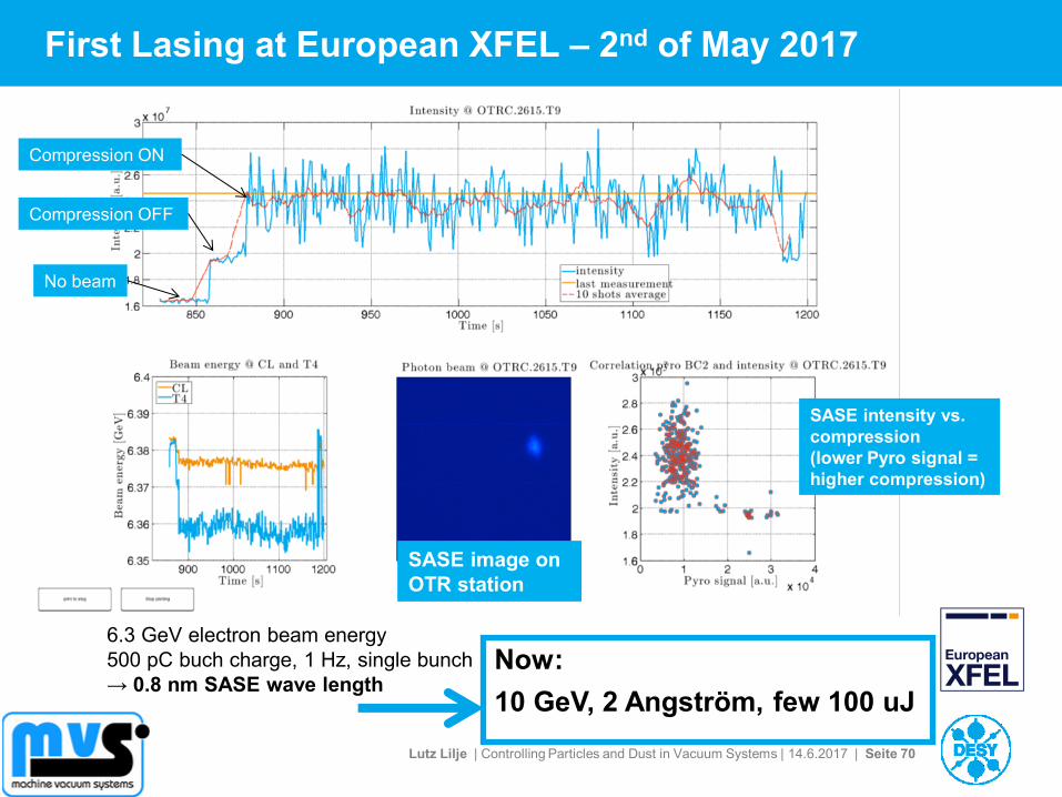
First Lasing at European XFEL – 2nd of May 2017
6.3 GeV electron beam energy
500 pC buch charge, 1 Hz, single bunch
→ 0.8 nm SASE wave length
SASE intensity vs.
compression
(lower Pyro signal =
higher compression)
SASE image on
OTR station
No beam
Compression OFF
Compression ON
Now:
10 GeV, 2 Angström, few 100 uJ

Lutz Lilje | Controlling Particles and Dust in Vacuum Systems | 14.6.2017 | Seite 71
Remember: Basic Rules for a „Particle-free“ Accelerator
> Avoid particulates at every stage and include it in the mechanical
design
> Remove particulates at every stage possible
> Do not produce particulates especially during installation and operation
> Never transport particulates
> … be prepared for reasonable compromises!
Lutz Lilje | Controlling Particles and Dust in Vacuum Systems | 14.6.2017 | Seite 72
Summary
> Remember the basic rules
> Layout and mechanical design need to take into account cleaning and
installation
> Transport of particulates must be avoided
Methods to avoid turbulent flows during pump-down and venting are
available
> Large-scale infrastructures can be built “particle-free”
A large part of the European XFEL accelerator vacuum system is „particle-
free“
… and it works!