Embed Size (px)
Citation preview
SPE-13-8-071/C/AS | page 1 of 22MA.520.C.B208111.C208151
MA520.A.BC.008
Specification
Part No. MA520.A.BC.008
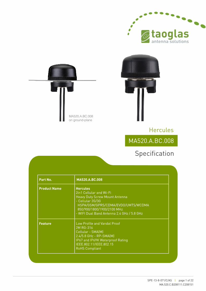
Product Name Hercules2in1 Cellular and Wi-Fi Heavy Duty Screw Mount Antenna - Cellular 2G/3G HSPA/GSM/GPRS/CDMA/EVDO/UMTS/WCDMA 850/900/1800/1900/2100 MHz- WIFI Dual Band Antenna 2.4 GHz / 5.8 GHz
Feature Low Profile and Vandal Proof 2M RG-316 Cellular - SMA(M)2.4/5.8 GHz - RP-SMA(M)IP67 and IP69K Waterproof RatingIEEE.802.11/IEEE.802.15RoHS Compliant
Hercules
MA520.A.BC.008 on ground-plane

SPE-13-8-071/C/AS | page 2 of 22MA.520.C.B208111.C208151
The MA520 Hercules 2in1 Penta Band Cellular-2.4/5.8GHz Antenna is the smallest package high performance screw-mount (permanent mount) antenna available, for external use on vehicles and outdoor assets worldwide.
Everything is in the one housing reducing the need for multiples antenna installations. This is the ideal antenna for 3G gateway routers that provide Wi-Fi hotspots.
It has been designed for heavy duty work with extra thick threads; with durable UV-resistant ABS housing is resistant to vandalism and direct attack.
At only 29mm high and 49mm in diameter this antenna enables covert operation and its quality is proven by growing adoption by many of the world’s largest wireless brands worldwide.
The standard cable length is 1 meter, the antenna can work to cable lengths of 2 meters. The Hercules MA520 exceptional design means it can work equally well mounted on or without ground-plane.
The antenna housing is completely waterproof to IP67, and also to IP69K, which means it is waterproof against high pressure water jets used in industrial environments for cleaning.
1. Introduction
SPE-13-8-071/C/AS | page 3 of 22MA.520.C.B208111.C208151
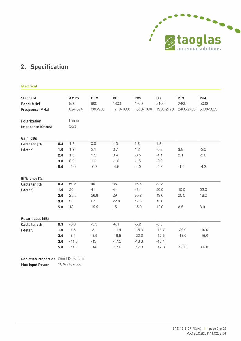
2. Specification
Standard AMPS GSM DCS PCS 3G ISM ISM
Band (MHz) 850 900 1800 1900 2100 2400 5000Frequency (MHz) 824-894 880-960 1710-1880 1850-1990 1920-2170 2400-2483 5000-5825
Polarization LinearImpedance (Ohms) 50Ω
Gain (dBi)
Cable length 0.3 1.7 0.9 1.3 3.5 1.5(Meter) 1.0 1.2 2.1 0.7 1.2 -0.3 3.8 -2.0
2.0 1.0 1.5 0.4 -0.5 -1.1 2.1 -3.23.0 0.9 1.0 -1.0 -1.5 -2.25.0 -1.0 -0.7 -4.5 -4.0 -4.3 -1.0 -4.2
Efficiency (%)
Cable length 0.3 50.5 40 38. 46.5 32.3(Meter) 1.0 29 41 41 43.4 29.9 40.0 22.0
2.0 23.5 26.8 29 20.2 19.6 20.0 18.03.0 25 27 22.0 17.8 15.05.0 18 15.5 15 15.0 12.0 8.5 8.0
Return Loss (dB)
Cable length 0.3 -6.0 -5.5 -6.1 -6.2 -5.8(Meter) 1.0 -7.8 -8 -11.4 -15.3 -13.7 -20.0 -10.0
2.0 -8.1 -8.5 -16.5 -20.3 -19.5 -18.0 -15.03.0 -11.0 -13 -17.5 -18.3 -18.15.0 -11.8 -14 -17.6 -17.8 -17.8 -25.0 -25.0
Radiation Properties Omni-DirectionalMax Input Power 10 Watts max.
Electrical

SPE-13-8-071/C/AS | page 4 of 22MA.520.C.B208111.C208151
2. Specification
Mechanical
Dimensions (mm) Height=29mm x Diameter=49mmCable 2 Meters RG316 (Fully Customizable)Connector Cellular: SMA(M) - Wi-Fi: RP-SMA(M) (Fully Customizable)Tread Diameter 18 mmCasing UV Resistant ABSWeather proof gasket CR4305 foam with 3M9448B double-side adhesiveSealant Rubber StopperBase and Thread Nickel Plated Zinc Alloy
Environmental
Protection IP67Corrosion 5% NACI for 96hrsTemperature Range -40ºC to +85ºCThermal Shock 100 cycles -40°C to +85°CHumidity Non-condensing 65°C 95% RHShock (Drop Test) 1m drop on concrete 6 axesCable Pull 8 Kgf
*Note: The MA520 antenna performance was measured on a 60X60cm metal plate
SPE-13-8-071/C/AS | page 5 of 22MA.520.C.B208111.C208151
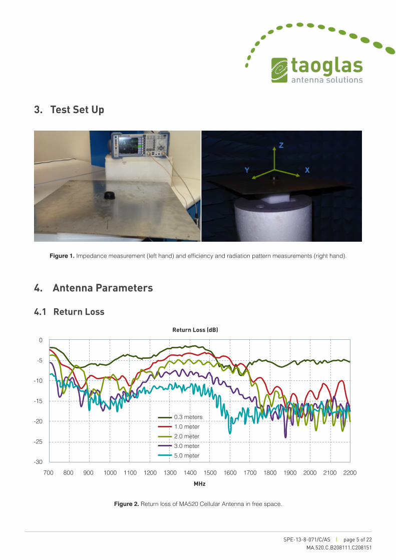
3. Test Set Up
Figure 1. Impedance measurement (left hand) and efficiency and radiation pattern measurements (right hand).
Figure 2. Return loss of MA520 Cellular Antenna in free space.
4. Antenna Parameters
4.1 Return Loss
0
-5
-10
-15
-20
-25
-30
700 800 900 1000 1100 1200 1300 1400 1500 1600 1700 1800 1900 2000 2100 2200
MHz
Return Loss (dB)
0.3 meters1.0 meter2.0 meter3.0 meter5.0 meter

SPE-13-8-071/C/AS | page 6 of 22MA.520.C.B208111.C208151
4. Antenna Parameters
4.1 Return Loss
Frequency (MHz)Figure 3. Return loss of MA520 Cellular Antenna on 30*30 cm metal plate.
Frequency (MHz)Figure 4. Return loss of MA520 Cellular Antenna on 60 *60 cm metal plate.
Ret
urn
Loss
(dB
) R
etur
n Lo
ss (d
B)
0
-5
-10
-15
-20
-25
-30700 800 900 1000 1100 1200 1300 1400 1500 1600 1700 1800 1900 2000 2100 2200
Return Loss (dB)
Return Loss (dB)
0.3 meters1.0 meter2.0 meter3.0 meter5.0 meter
0
-5
-10
-15
-20
-25
-30700 800 900 1000 1100 1200 1300 1400 1500 1600 1700 1800 1900 2000 2100 2200
0.3 meters1.0 meter2.0 meter3.0 meter5.0 meter
SPE-13-8-071/C/AS | page 7 of 22MA.520.C.B208111.C208151
4. Antenna Parameters
4.1 Return Loss
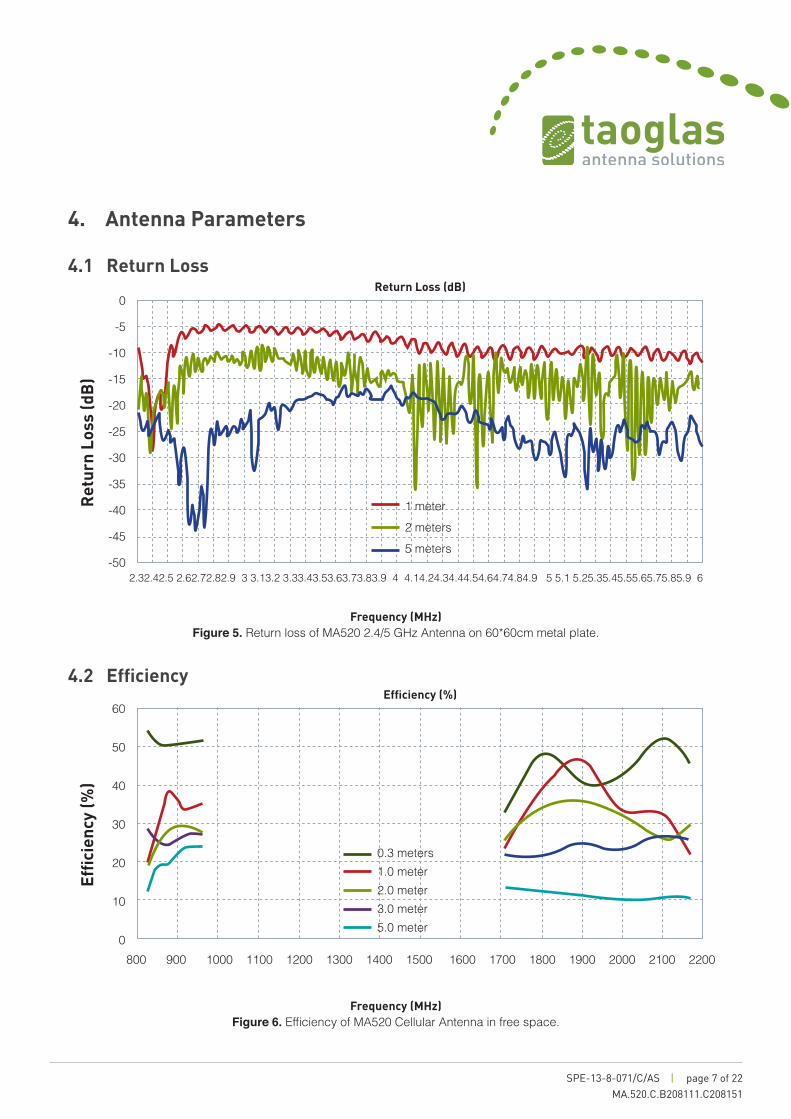
4.2 Efficiency
Frequency (MHz)Figure 5. Return loss of MA520 2.4/5 GHz Antenna on 60*60cm metal plate.
Frequency (MHz)Figure 6. Efficiency of MA520 Cellular Antenna in free space.
Effic
ienc
y (%
) R
etur
n Lo
ss (d
B)
0
-5
-10
-15
-20
-25
-30
-35
-40
-45
-502.32.42.5 2.62.72.82.9 3 3.13.2 3.33.43.53.63.73.83.9 4 4.14.24.34.44.54.64.74.84.9 5 5.1 5.25.35.45.55.65.75.85.9 6
1 meter2 meters5 meters
60
50
40
30
20
10
0800 900 1000 1100 1200 1300 1400 1500 1600 1700 1800 1900 2000 2100 2200
0.3 meters1.0 meter2.0 meter3.0 meter5.0 meter
Return Loss (dB)
Efficiency (%)

SPE-13-8-071/C/AS | page 8 of 22MA.520.C.B208111.C208151
Frequency (MHz)Figure 7. Efficiency of MA520 Cellular Antenna on 30*30cm metal plate
Frequency (MHz)Figure 8. Efficiency of MA520 Cellular Antenna on 60*60 cm metal plate.
Effic
ienc
y (%
)Ef
ficie
ncy
(%)
4.2 Efficiency
4. Antenna Parameters
60
50
40
30
20
10
0
0.3 meters1.0 meter2.0 meter3.0 meter5.0 meter
800 900 1000 1100 1200 1300 1400 1500 1600 1700 1800 1900 2000 2100 2200
60
50
40
30
20
10
0800 900 1000 1100 1200 1300 1400 1500 1600 1700 1800 1900 2000 2100 2200
0.3 meters1.0 meter2.0 meter3.0 meter5.0 meter
Efficiency (%)
Efficiency (%)

SPE-13-8-071/C/AS | page 9 of 22MA.520.C.B208111.C208151
Frequency (MHz)Figure 9. Efficiency of MA520 2.4/5 GHz Antenna on 60*60 cm metal plate.
Frequency (MHz)Figure 10. Gain of MA520 Cellular Antenna in free space.
Gai
n (d
Bi)
Effic
ienc
y (%
)
4.2 Efficiency
4.2 Gain
4. Antenna Parameters
5
4
3
2
1
0
-1
-2
-3
-4
-5
0.3 meters1.0 meter2.0 meter3.0 meter5.0 meter
800 900 1000 1100 1200 1300 1400 1500 1600 1700 1800 1900 2000 2100 2200
50
45
40
35
30
25
20
15
10
5
02300 2500 2700 2900 3100 3300 3500 3700 3600 4100 4300 4500 4700 4900 5100 5300 5500 5700 5900
Efficiency (%)
Efficiency (%)
1 meter2 meters5 meters
SPE-13-8-071/C/AS | page 10 of 22MA.520.C.B208111.C208151
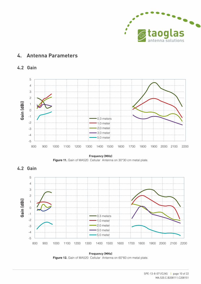
Frequency (MHz)Figure 11. Gain of MA520 Cellular Antenna on 30*30 cm metal plate.
Frequency (MHz)Figure 12. Gain of MA520 Cellular Antenna on 60*60 cm metal plate.
Gai
n (d
Bi)
Gai
n (d
Bi)
4.2 Gain
4.2 Gain
4. Antenna Parameters
5
4
3
2
1
0
-1
-2
-3
-4
-5
0.3 meters1.0 meter2.0 meter3.0 meter5.0 meter
800 900 1000 1100 1200 1300 1400 1500 1600 1700 1800 1900 2000 2100 2200
5
4
3
2
1
0
-1
-2
-3
-4
-5800 900 1000 1100 1200 1300 1400 1500 1600 1700 1800 1900 2000 2100 2200
0.3 meters1.0 meter2.0 meter3.0 meter5.0 meter
SPE-13-8-071/C/AS | page 11 of 22MA.520.C.B208111.C208151
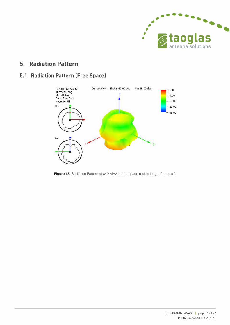
5.1 Radiation Pattern (Free Space)
5. Radiation Pattern
Figure 13. Radiation Pattern at 849 MHz in free space (cable length 2 meters).
SPE-13-8-071/C/AS | page 12 of 22MA.520.C.B208111.C208151
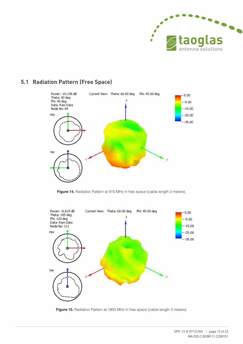
5.1 Radiation Pattern (Free Space)
Figure 14. Radiation Pattern at 915 MHz in free space (cable length 2 meters).
Figure 15. Radiation Pattern at 1805 MHz in free space (cable length 2 meters).

SPE-13-8-071/C/AS | page 13 of 22MA.520.C.B208111.C208151
5.1 Radiation Pattern (Free Space)
Figure 16. Radiation Pattern at 1910 MHz in free space (cable length 2 meters).
Figure 17. Radiation Pattern at 2110 MHz in free space (cable length 2 meters).

SPE-13-8-071/C/AS | page 14 of 22MA.520.C.B208111.C208151
5.2 Radiation Pattern (30*30 mm Ground Plane)
Figure 18. Radiation Pattern at 849 MHz (cable length 2 meters).
Figure 19. Radiation Pattern at 915 MHz (cable length 2 meters).
SPE-13-8-071/C/AS | page 15 of 22MA.520.C.B208111.C208151
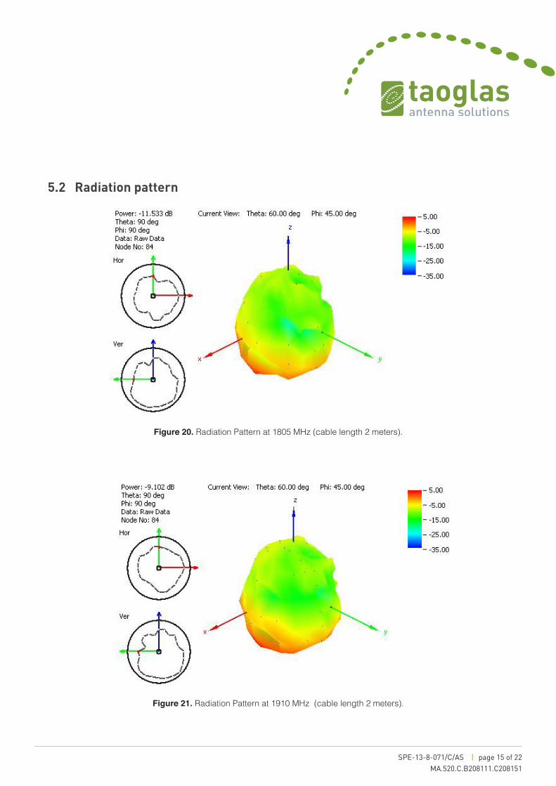
5.2 Radiation pattern
Figure 20. Radiation Pattern at 1805 MHz (cable length 2 meters).
Figure 21. Radiation Pattern at 1910 MHz (cable length 2 meters).

SPE-13-8-071/C/AS | page 16 of 22MA.520.C.B208111.C208151
5.2 Radiation pattern
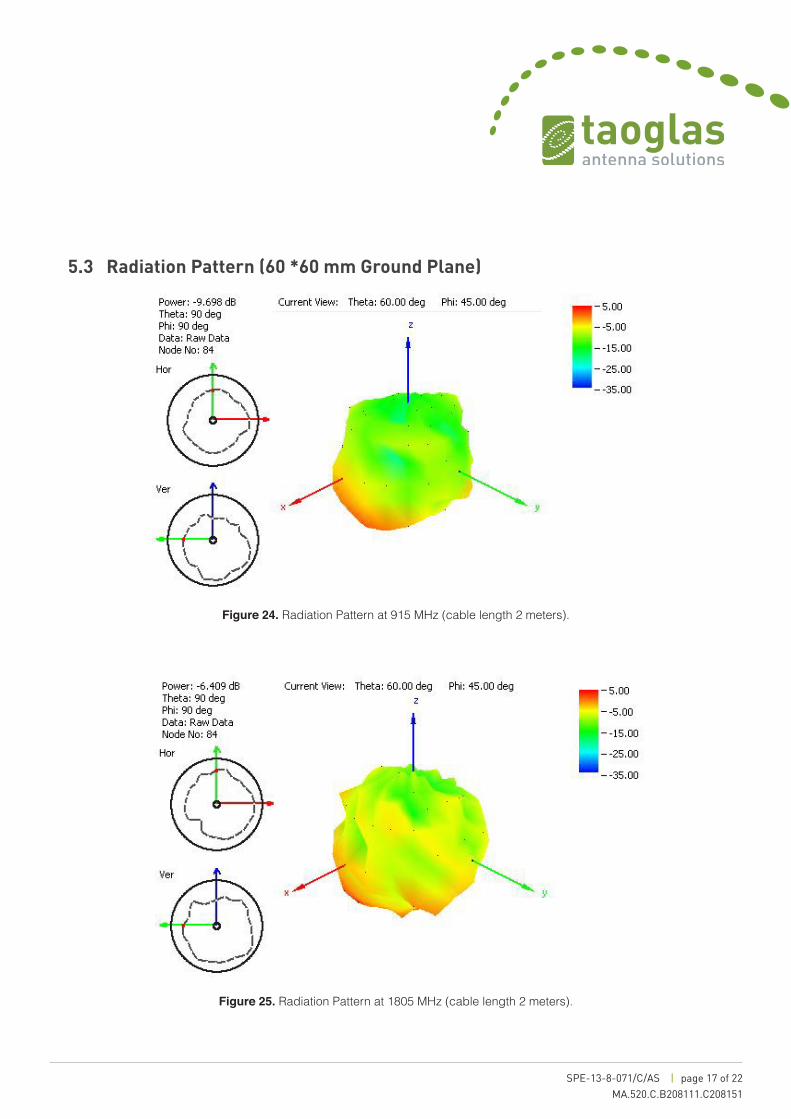
5.3 Radiation Pattern (60 *60 mm Ground Plane)
Figure 22. Radiation Pattern at 2110 MHz (cable length 2 meters).
Figure 23. Radiation Pattern at 849 MHz (cable length 2 meters).
SPE-13-8-071/C/AS | page 17 of 22MA.520.C.B208111.C208151
5.3 Radiation Pattern (60 *60 mm Ground Plane)
Figure 24. Radiation Pattern at 915 MHz (cable length 2 meters).
Figure 25. Radiation Pattern at 1805 MHz (cable length 2 meters).
SPE-13-8-071/C/AS | page 18 of 22MA.520.C.B208111.C208151
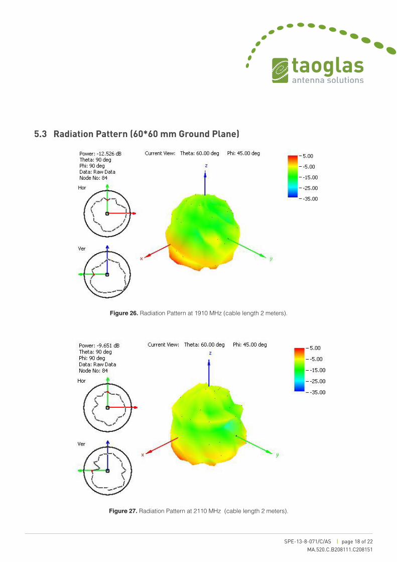
5.3 Radiation Pattern (60*60 mm Ground Plane)
Figure 26. Radiation Pattern at 1910 MHz (cable length 2 meters).
Figure 27. Radiation Pattern at 2110 MHz (cable length 2 meters).
SPE-13-8-071/C/AS | page 19 of 22MA.520.C.B208111.C208151
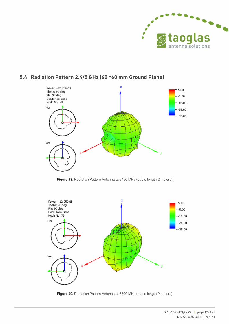
5.4 Radiation Pattern 2.4/5 GHz (60 *60 mm Ground Plane)
Figure 28. Radiation Pattern Antenna at 2450 MHz (cable length 2 meters)
Figure 29. Radiation Pattern Antenna at 5500 MHz (cable length 2 meters)
SPE-13-8-071/C/AS | page 20 of 22MA.520.C.B208111.C208151
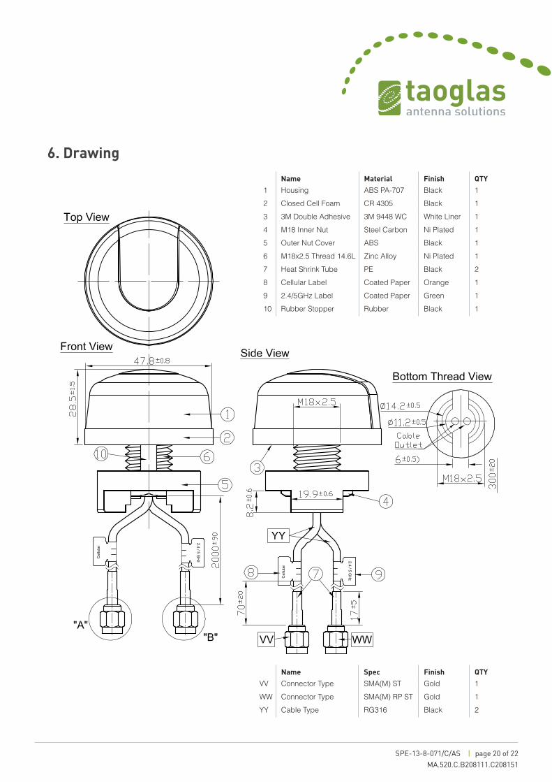
6. Drawing
Name Material Finish QTY
1 Housing ABS PA-707 Black 12 Closed Cell Foam CR 4305 Black 13 3M Double Adhesive 3M 9448 WC White Liner 14 M18 Inner Nut Steel Carbon Ni Plated 15 Outer Nut Cover ABS Black 16 M18x2.5 Thread 14.6L Zinc Alloy Ni Plated 17 Heat Shrink Tube PE Black 28 Cellular Label Coated Paper Orange 19 2.4/5GHz Label Coated Paper Green 110 Rubber Stopper Rubber Black 1
Name Spec Finish QTY
VV Connector Type SMA(M) ST Gold 1WW Connector Type SMA(M) RP ST Gold 1YY Cable Type RG316 Black 2
SPE-13-8-071/C/AS | page 21 of 22MA.520.C.B208111.C208151
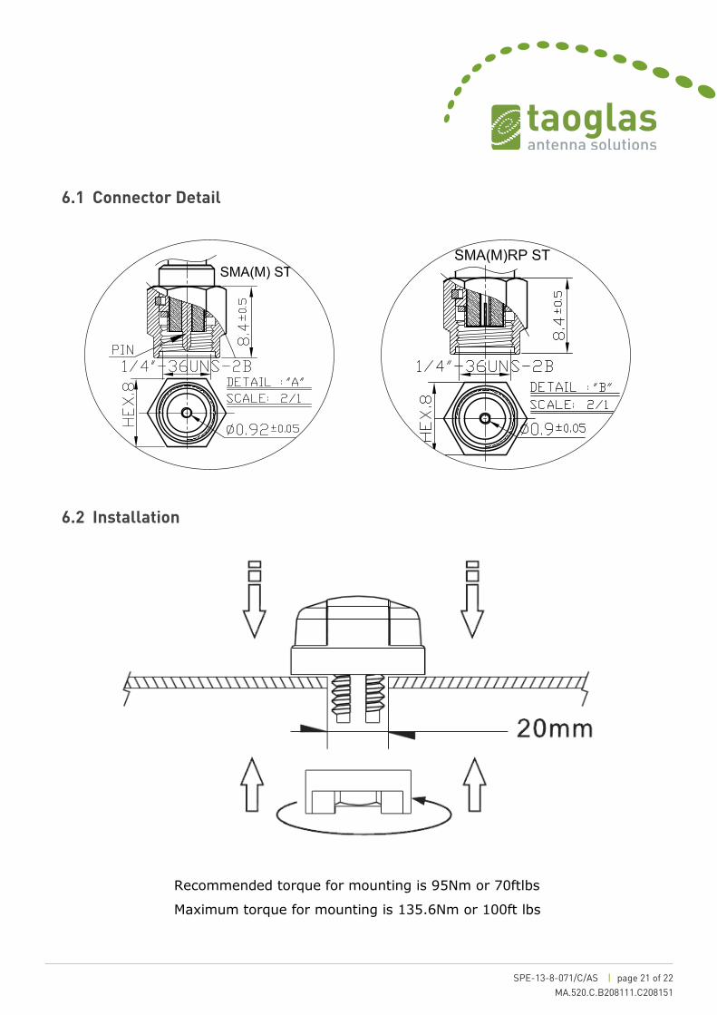
6.1 Connector Detail
6.2 Installation
SPE-11-8-054/E/SS Page 23 of 23
9.0 Installation
Recommended torque for mounting is 95Nm or 70ftlbs
Maximum torque for mounting is 135.6Nm or 100ft lbs
SPE-11-8-054/E/SS Page 23 of 23
9.0 Installation
Recommended torque for mounting is 95Nm or 70ftlbs
Maximum torque for mounting is 135.6Nm or 100ft lbs

SPE-13-8-071/C/AS | page 22 of 22MA.520.C.B208111.C208151
7. Packaging
Taoglas makes no warranties based on the accuracy or completeness of the contents of this document and reserves the right to make changes to specifications and
product descriptions at any time without notice. Taoglas reserves all rights to this document and the information contained herein.
Reproduction, use or disclosure to third parties without express permission is strictly prohibited. Copyright © Taoglas Ltd.