Embed Size (px)
Citation preview

SPE-11-8-032/F/SS | page 1 of 16
TG.09.0113
Specification
Part No. TG.09.0113
Product Name Penta-band Cellular Hinged SMA Male Monopole
Feature 800 MHz to 2200MHzGSM/CDMA/HSPA/UMTSRotatable hinge design for optimal receptionTop quality housing with brass hinge and connectorExtended operation temperature rangeRoHS Compliant
This drawing and its inherent design concepts are property of Taoglas. Not tobe copied or given to third parties without the written consent of Taoglas.
TW Design Centre
ALL Initial Design Jason 2011/6/15A
ALL Add 3D View Jason 2011/8/1B
3D View
Name Material Finish QTY
Housing
SMA(M) ST
POM Black
Ni Plated
1
1
1
1
1
2
3
4
Ni Plated
Black
Hinge Brass
POM
Brass
Cap
Pin
A2 Amend Typo Kiwi 2011/10/5C
C

SPE-11-8-032/F/SS | page 2 of 16
The TG.09 Penta-band Cellular Hinged Rotatable SMA antenna is a high efficiency monopole antenna. Compared to other much larger antennas on the market, it has superior wide-band high efficiency characteristics.
This antenna is used by many of the leading wireless device providers in the world marketplace.
The unique rotatable hinge design enables the user to rotate the antenna to the best angle for an optimal cellular signal reception. As the upper antenna element can move in any direction, it also reduces damage from impact force from any angle to the antenna, compared to traditional hinged right angle or fixed fight angle designs or straight antennas.
The tiny dimensions of this antenna coupled with excellent RF performance and an aesthetic high end design feel make it the ideal cellular antenna for routers, vehicle tracking devices, telematics devices, remote monitoring systems, POS devices.
The TG.09 as all monopole antennas works best connected directly to the ground-plane of the device main-board. Taoglas offers support services to characterize antenna efficiency on your individual device ground-plane.
Please contact Taoglas regional support centre first if you wish to do PTCRB or network approvals with this antenna attached to your device, so we can check RF integration is correct and do
a pre-test first to ensure optimized passive and active performance and a smooth and quick certification approval process.
This antenna also comes in a white version. TG.09.0113W
If your device does not have a direct connection to ground-plane, please consider using our TG.30 Apex Wideband Dipole Cellular Antenna, which does not need a ground-plane to connect to.
1. Introduction

SPE-11-8-032/F/SS | page 3 of 16
2. Specification
* Average efficiency and peak gain of antenna sitting 180º in free space and mounted at the side of the PCB. Please refer to section IV for testing detail.
Electrical
Penta-band CellularCommunication System AMPS GSM DCS PCS UMTSFrequency 824 ~ 896 880 ~ 960 1710 ~ 1880 1850 ~ 1990 1710 ~ 2170Efficiency (free space)* 21% 24% 23% 32% 31%Gain (dBi, free space)* 2.0 2.0 -1.0 -0.4 -0.1Efficiency (mounted on PCB)* 39% 31% 78% 75% 75%Gain (dBi, mounted on PCB)* 1.0 -1.0 2.8 2.8 2.0Impedance 50ΩPolarization LinearRadiation Pattern Omni-directionalInput Power 10 W
Mechanical
Antenna Length 72 ± 1.5 mmAntenna Diameter 10 ± 0.3 mmCasing POMConnector SMA Male (Brass)
Environmental
Temperature Range -40°C to 85°CStorage Temperature -40℃ ~ +105℃Humidity Non-condensing 65°C 95% RH
0
-5
-10
-15
-20
-25
600 800 1000 1200 1400 1600 1800 2000 2200 2400 (MHz)
TG.09 Return Loss
TG.09 tested with Agilent 8753ES
straight
bend
SPE-11-8-032/F/SS | page 4 of 16
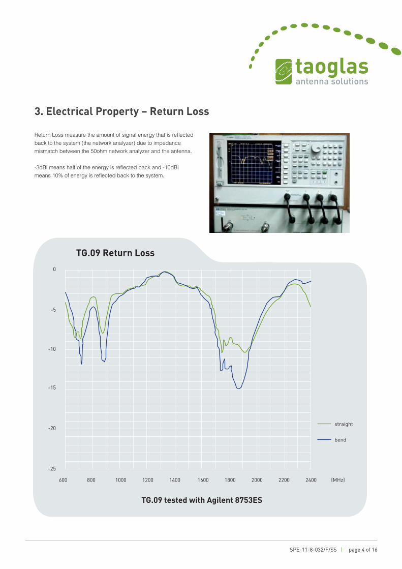
Return Loss measure the amount of signal energy that is reflected back to the system (the network analyzer) due to impedance mismatch between the 50ohm network analyzer and the antenna.
-3dBi means half of the energy is reflected back and -10dBimeans 10% of energy is reflected back to the system.
3. Electrical Property – Return Loss
SPE-11-8-032/F/SS Page 4 of 17
3. Electrical Property – Return Loss
Return Loss measure the amount of signal energy that is reflected back to the system
(the network analyzer) due to impedance mismatch between the 50ohm network
analyzer and the antenna. -3dBi means half of the energy is reflected back and -10dBi
means 10% of energy is reflected back to the system.
TG.09 Return Loss
-25
-20
-15
-10
-5
0
600 800 1000 1200 1400 1600 1800 2000 2200 2400 (MHz)
straight
bend
TG.09 tested with Agilent 8753ES

SPE-11-8-032/F/SS | page 5 of 16
4. Electrical Property – Efficiency
Antenna normally behaves differently when mounting on a different environment.So we test the antenna in four different settings –
a) free space
b) on top of a 150 x 90mm ground plane.(A common ground plane size for electronic device)
c) on the edge of a 150 x 90mm ground plane. (Another common way of mounting antenna)
d) 450 x 350 ground plane. This simulates the situation of mounting TG.09 on top of a large metal object, such as a vehicle.
TG.09 can be installed in 5 different angles so we present the test in different combination of angles and mounting environment.
SPE-11-8-032/F/SS Page 5 of 17
4. Electrical Property – Efficiency
Antenna normally behaves differently when mounting on a different environment.
So we test the antenna in four different settings –
a. free space
b. on top of a 150 x 90mm ground plane.(A common ground plane size for
electronic device)
c. on the edge of a 150 x 90mm ground plane. (Another common way of mounting
antenna)
d. 450 x 350 ground plane. This simulates the situation of mounting TG.09 on top
of a large metal object, such as a vehicle.
TG.09 can be installed in 5 different angles so we present the test in different
combination of angles and mounting environment.
1. free space 2. PCB size ground plane
3. mounting upright 4. metal plane
1. Free Space
3. Mounting Upright
2. PCB Size Ground Plane
4. Metal Plane
SPE-11-8-032/F/SS Page 6 of 17
TG.09 on top of a 150x90mm PCB. ψis the horizontal rotation and θ is the vertical position of TG.09 with respect to the 3D chamber. In the Satimo chamber, ψ= 0 is the
x-axial, ψ= 90o is the y-axial and θ=180o is the z-axial.
ψ
θ
θ= 90o
= θ= 270o
ψ=90o
ψ
=180o
ψ= 0o
TG.09 on top of a 150 x 90mm PCB. Ø is the horizontal rotation and 0 is the vertical position of TG.09 with respect to the 3D chamber.
In the Satimo chamber, Ø = 0 is the x-axial, Ø = 90º is the y-axial and 0 =180º is the z-axial.

SPE-11-8-032/F/SS | page 6 of 16
4.1 TG.09 on Different Mounting Condition
Here we compare TG.09 in its most common installation angles (90º and 180º) with different mounting environments.
Antenna in straight position (180º) on different mounting condition.
SPE-11-8-032/F/SS Page 7 of 17
4.1 TG.09 on Different Mounting Condition Here we compare TG.09 in its most common installation angles (90o and 180o) with
different mounting environments.
Radiation efficiency -- TG.09 180 degree
0%
10%
20%
30%
40%
50%
60%
70%
80%
90%
600 800 1000 1200 1400 1600 1800 2000 2200 2400 (MHz)
pcb 180metal 180upright 180freespace 180
Antenna in straight position (180o) on different mounting condition.
Radiation efficiency - TG.09 180 degree
90%
80%
70%
60%
50%
40%
30%
20%
10%
0%
600 800 1000 1200 1400 1600 1800 2000 2200 2400 (MHz)

SPE-11-8-032/F/SS | page 7 of 16
Antenna in right angle position (90º) on different mounting condition.
TG.09 is a monopole antenna. It works better with the present of a ground plane. The size of the ground plane does not affect the radiation efficiency much as long as it is greater than 1/4 wavelength (1/4 wavelength for 824MHz is 91mm).
Radiation efficiency - TG.09 90 degree
4.1 TG.09 on Different Mounting Condition
SPE-11-8-032/F/SS Page 8 of 17
Radiation efficiency -- TG.09 90 degree
0%
10%
20%
30%
40%
50%
60%
70%
80%
90%
600 800 1000 1200 1400 1600 1800 2000 2200 2400 (MHz)
pcb 90metal 90upright 90freespace 90
Antenna in right angle position (90o) on different mounting condition.
TG.09 is a monopole antenna. It works better with the present of a ground plane. The
size of the ground plane does not affect the radiation efficiency much as long as it is
greater than 1/4 wavelength (1/4 wavelength for 824MHz is 91mm).
90%
80%
70%
60%
50%
40%
30%
20%
10%
0%600 800 1000 1200 1400 1600 1800 2000 2200 2400 (MHz)

SPE-11-8-032/F/SS | page 8 of 16
4.2 TG.09 - Different Rotation Angle
TG.09 has 5 different locking 0 angle and is free to mount at any angle around Ø.Different position of antenna with respect to the ground has different antennaradiation. We tested TG.09 in three common situation of antenna mounting.
SPE-11-8-032/F/SS Page 9 of 17
4.2 TG.09 - Different Rotation Angle TG.09 has 5 different lockingθ angle and is free to mount at any angle aroundψ.
Different position of antenna with respect to the ground has different antenna
radiation. We tested TG.09 in three common situation of antenna mounting.
Different antenna mounting is marked as (ψangle--θangel ), photos are two example
of the position marking.
TG.09 mounted on PCB ground
0%
10%
20%
30%
40%
50%
60%
70%
80%
90%
600 800 1000 1200 1400 1600 1800 2000 2200 2400 (MHz)
1800-900-135315-90315-135270-90270-135225-90225-135
0 - 135
270 - 90
Different antenna mounting is marked as (Ø angle--0 angle ), photos are two exampleof the position marking.
90%
80%
70%
60%
50%
40%
30%
20%
10%
0%
600 800 1000 1200 1400 1600 1800 2000 2200 2400 (MHz)
TG.09 mounted on PCB ground

SPE-11-8-032/F/SS | page 9 of 16
SPE-11-8-032/F/SS Page 10 of 17
Example of upright mounting.
TG.09 mounted at the edge of PCB (upright position)
0%
10%
20%
30%
40%
50%
60%
70%
80%
90%
600 800 1000 1200 1400 1600 1800 2000 2200 2400(MHz)
180315-90315-135270-90270-135225-90225-135180-90180-135
0 - 90
90 - 135
Example of upright mounting.
SPE-11-8-032/F/SS Page 10 of 17
Example of upright mounting.
TG.09 mounted at the edge of PCB (upright position)
0%
10%
20%
30%
40%
50%
60%
70%
80%
90%
600 800 1000 1200 1400 1600 1800 2000 2200 2400(MHz)
180315-90315-135270-90270-135225-90225-135180-90180-135
0 - 90
90 - 135
4.2 TG.09 - Different Rotation Angle
TG.09 mounted at the edge of PCB (upright position)
90%
80%
70%
60%
50%
40%
30%
20%
10%
0%
600 800 1000 1200 1400 1600 1800 2000 2200 2400 (MHz)

SPE-11-8-032/F/SS | page 10 of 16
SPE-11-8-032/F/SS Page 11 of 17
Example of TG.09 mounting on metal plane.
TG.09 mounted on metal plane
0%
10%
20%
30%
40%
50%
60%
70%
80%
90%
600 800 1000 1200 1400 1600 1800 2000 2200 2400(MHz)
0-90
0-135
180
Different ground plane let TG.09 have very different efficiency distribution. Different
TG.09 rotation for any given mounting ground has up to 20% efficiency different for
each frequency, but has similar efficiency distribution.
0 - 135
Example of TG.09 mounting on metal plane.
SPE-11-8-032/F/SS Page 11 of 17
Example of TG.09 mounting on metal plane.
TG.09 mounted on metal plane
0%
10%
20%
30%
40%
50%
60%
70%
80%
90%
600 800 1000 1200 1400 1600 1800 2000 2200 2400(MHz)
0-90
0-135
180
Different ground plane let TG.09 have very different efficiency distribution. Different
TG.09 rotation for any given mounting ground has up to 20% efficiency different for
each frequency, but has similar efficiency distribution.
0 - 135
Different ground plane let TG.09 have very different efficiency distribution. Different TG.09 rotation for any given mounting ground has up to 20% efficiency different for
each frequency, but has similar efficiency distribution.
90%
80%
70%
60%
50%
40%
30%
20%
10%
0%
600 800 1000 1200 1400 1600 1800 2000 2200 2400 (MHz)
TG.09 mounted on metal plane

SPE-11-8-032/F/SS | page 11 of 16
5. Radiation Pattern
SPE-11-8-032/F/SS Page 12 of 17
5. Radiation Pattern
5.1 TG.09 in Free Space
Vertical Horizontal
TG.09 180o in free space
-35
-30
-25
-20
-15
-10
-5
0
-35
-30
-25
-20
-15
-10
-5
0
850MHz
900MHz
1800MHz
1900MHz
2100MHz TG.09 90o in free space
-35
-30
-25
-20
-15
-10
-5
0
5
-30
-25
-20
-15
-10
-5
0
850MHz
900MHz
1800MHz
1900MHz
2100MHz
Vertical Horizontal
TG.09 180° in free space
TG.09 90° in free space
5.1 TG.09 in Free Space

SPE-11-8-032/F/SS | page 12 of 16
5.2 TG.09 Mounted on PCB
SPE-11-8-032/F/SS Page 13 of 17
5.2 TG.09 Mounted on PCB
Vertical Horizontal
TG.09 180o on PCB
-35
-30
-25
-20
-15
-10
-5
0
5
-35
-30
-25
-20
-15
-10
-5
0
850MHz
900MHz
1800MHz
1900MHz
2170MHz
TG.09 90o on PCB (0-90)
-35
-30
-25
-20
-15
-10
-5
0
5
-35
-30
-25
-20
-15
-10
-5
0
850MHz
900MHz
1800MHz
1900MHz
2170MHz
Vertical Horizontal
TG.09 180° on PCB
TG.09 90° on PCB (0-90)

SPE-11-8-032/F/SS | page 13 of 16
5.3 TG.09 Mounted At a Side of PCB
SPE-11-8-032/F/SS Page 14 of 17
5.3 TG.09 Mounted At a Side of PCB
Vertical Horizontal
TG.09 180o mounted at the side of PCB
-35
-30
-25
-20
-15
-10
-5
0
5
-35
-30
-25
-20
-15
-10
-5
0
5
850MHz
900MHz
1800MHz
1900MHz
2170MHz
TG.09 90o mounted at the side of PCB (270-90)
-35
-30
-25
-20
-15
-10
-5
0
5
-35
-30
-25
-20
-15
-10
-5
0
5
850MHz
900MHz
1800MHz
1900MHz
2170MHz
Vertical Horizontal
TG.09 180° mounted at the side of PCB
TG.09 90° mounted at the side of PCB (270-90)

SPE-11-8-032/F/SS | page 14 of 16
5.4 TG.09 Mounted on a Metal Plane
SPE-11-8-032/F/SS Page 15 of 17
5.4 TG.09 Mounted on a Metal Plane
Vertical Horizontal
TG.09 180o mounted on metal plane
-35
-30
-25
-20
-15
-10
-5
0
5
-35
-30
-25
-20
-15
-10
-5
0
850MHz
900MHz
1800MHz
1900MHz
2170MHz
TG.09 90o mounted on metal plane (0-90)
-35
-30
-25
-20
-15
-10
-5
0
5
-35
-30
-25
-20
-15
-10
-5
0
850MHz
900MHz
1800MHz
1900MHz
2170MHz
Vertical Horizontal
TG.09 180° mounted on metal plane
TG.09 90° mounted on metal plane (0-90)

SPE-11-8-032/F/SS | page 15 of 16
6. Mechanical Drawing (unit:mm)
This drawing and its inherent design concepts are property of Taoglas. Not tobe copied or given to third parties without the written consent of Taoglas.
TW Design Centre
ALL Initial Design Jason 2011/6/15A
ALL Add 3D View Jason 2011/8/1B
3D View
Name Material Finish QTY
Housing
SMA(M) ST
POM Black
Ni Plated
1
1
1
1
1
2
3
4
Ni Plated
Black
Hinge Brass
POM
Brass
Cap
Pin
A2 Amend Typo Kiwi 2011/10/5C
C
1 Housing POM Black
2 Hinge Brass Ni Plated
3 Cap POM Black
4 Connector SMA Male (Brass)

SPE-11-8-032/F/SS | page 16 of 16
7. Packaging
1pcs antennas per small PE bag.
100 small PE bags per big PE bag.
100pcs antennas per big sealed PE bag.
Taoglas makes no warranties based on the accuracy or completeness of the contents of this document and reserves the right to make changes to specifications and
product descriptions at any time without notice. Taoglas reserves all rights to this document and the information
contained herein. Reproduction, use or disclosure to third parties without express permission is strictly prohibited. Copyright © Taoglas Ltd.
UNLESS OTHER SPECIFIED TOLERANCES ON: X=± X.X=± X.XX= ANGLES=± HOLEDIA=± SCALE: xxxx UNIT:mm DRAWN BY: jason CHECKED BY: Jimmy DESIGNED BY: Jimmy APPROVED BY: Jimmy
DOCUMENT PAGE REV. TITLE: TG.09 Antenna Assembly NO.
ISO NO: PSP-12-8-00 PAGE 6 OF 6
5 包裝規格
5.1 每個小 PE 袋放置 1 天線 【1pcs antennas per small PE bag.】 5.2 每個大 PE 袋放置 100 個小 PE 袋,如下圖所示 【100 small PE bags per big PE bag.】 5.3 每包大 PE 袋內數量共 100pcs 天線 【100pcs antennas per big PE bag.】 5.4 封口時須注意不可壓到天線,裝入需平整不可雜亂
【Antenna should be placed flat and neat in the PE bag. Hot seal the PE bag without pressing or damage the antenna.】
5.5 清點每袋數量不可短缺 【Confirm the quantity in each PE bag.】
100 PCS PE Bag
1 PCS Bag
大 PE 袋
TG.09
小 PE 袋