Embed Size (px)
Citation preview
Network Video Recorder User’s Manual
Seyeon Tech Co., Ltd
User’s Guide
FlexWATCHTM 5000
(Version. 3.0_Rev0)
Seyeon Technology Co., Ltd
www.flexwatch.com
Network Video Recorder User’s Manual
Seyeon Tech Co., Ltd
2
Table of Contents
Overview of FlexWATCHTM Server............................................................8
1 Packing List................................................................................................ 8
2 What is FlexWATCHTM NDVR server ?.............................................................. 9
2.1 Key Function of FlexWATCHTM 5000 ....................................................... 9 2.2 Product Specification ......................................................................... 10 2.3 Application ....................................................................................... 11
Hardware Description............................................................................12 1.1 Caution and observance ..................................................................... 12 1.2 Hardware Description......................................................................... 12
IP assignment .......................................................................................15
1 Key Words for Network .............................................................................. 15
2 Check Points before IP assignment .............................................................. 17
2.1 IP address........................................................................................ 17 2.2 LAN cable or Cross-Over Cable............................................................ 19 2.3 PC Environment ................................................................................ 20
3 Factory Default ......................................................................................... 21
4 IP Assignment .......................................................................................... 21
4.1 Hardware Configuration...................................................................... 21 4.2 Through Installation Wizard Program ................................................... 23 4.3 IP Assignment through Hyper Terminal mode ........................................ 25
Live view...............................................................................................30
1 Live view program installation..................................................................... 30
2 Live View page guide................................................................................. 31
Network Video Recorder User’s Manual
Seyeon Tech Co., Ltd
3
System Configuration............................................................................33
1 System Information................................................................................... 33
2 Date & Time............................................................................................. 33
2.1 Date & Time in the server clock........................................................... 33 2.2 Date & Time using NTP server............................................................. 34
3 Admin Password Setup .............................................................................. 34
4 Access Control and User registration ............................................................ 34
4.1 Full Access ....................................................................................... 35 4.2 Limited Access and User registration .................................................... 35
5 Frame rate control .................................................................................... 37
6 Rx Module Registration .............................................................................. 38
6.1 Rx Module Connection type................................................................. 38 6.2 Rx Module Registration Example.......................................................... 41
Network Configuration ..........................................................................45
1 Network Configuration ............................................................................... 45
1.1 Static IP .......................................................................................... 45 1.2 DHCP Client...................................................................................... 46 1.3 PPPoE Configuration .......................................................................... 47
2 Local Network........................................................................................... 48
3 Port Mapping ............................................................................................ 49
3.1 Port Mapping Example ....................................................................... 50
4 Network port configuration ......................................................................... 51
4.1 HTTP port configuration...................................................................... 51
Network Video Recorder User’s Manual
Seyeon Tech Co., Ltd
4
4.2 NIPP Port ......................................................................................... 52 4.3 NVCP –Rx Port .................................................................................. 52
5 WAN Configuration and Application .............................................................. 52
5.1 External Modem connection ................................................................ 52 5.2 Application with Dial-in/out feature...................................................... 53 5.3 Dial Out configuration ........................................................................ 53 5.4 Dial-in Configuration.......................................................................... 55
6 Network Status Notify................................................................................ 56
7 Service patch ........................................................................................... 57
8 AOIP Setup .............................................................................................. 58
8.1 How to use AOIP service .................................................................... 58 8.2 AOIP configuration ............................................................................ 59
9 Network Status......................................................................................... 59
Recording & Playback............................................................................61
1 General Setting for Recording ..................................................................... 61
1.1 Hard Disk Configuration ..................................................................... 61 1.2 Recording Mode ................................................................................ 64 1.3 HDD Status Report ............................................................................ 65
2 Recording Configuration ............................................................................. 66
2.1 Recording Configuration Procedure ...................................................... 66 2.2 Recording Frame rate Control.............................................................. 67 2.3 Recording by Motion detection ............................................................ 68 2.4 Recording condition ........................................................................... 69 2.5 Recording condition example .............................................................. 69
3 Playback of Archived Video ......................................................................... 73
Network Video Recorder User’s Manual
Seyeon Tech Co., Ltd
5
Utilities..................................................................................................75
1 Save Configuration.................................................................................... 75
2 Reboot .................................................................................................... 75
3 Factory Default ......................................................................................... 75
4 System Update ......................................................................................... 76
4.1 Description of files system.................................................................. 76 4.2 Update Procedure.............................................................................. 77
Network Video Recorder User’s Manual
Seyeon Tech Co., Ltd
6
Notice
• The material in this document is for information only and is subject to change without
notice. While reasonable efforts have been made in the preparation of this document to
assure its accuracy, Seyeon Tech assumes no liability resulting from errors or omissions
in this document, or from the use of the information contained herein.
• Seyeon Tech reserves the right to make changes in the product design without
reservation and without notification to its users.
Copyright
Copyright 1999-2004 Seyeon Tech Co., Ltd. All rights reserved. No part of this
publication may be reproduced, stored in a retrieval system, or transmitted in any form
or by any means, electronic, mechanical, photocopying, recording or otherwise, without
the prior written consent of Seyeon Tech Co., Ltd.
Copyright 1999-2004 Seyeon Tech Co., Ltd.
810-12 Yeok Sam-dong,
Kang Nam-gu, SEOUL,
135-081,KOREA
TEL : 82 2 3017 0855
FAX : 82 2 3017 0843
URL : http://www.seyeon.co.kr
http://www.flexwatch.com
Network Video Recorder User’s Manual
Seyeon Tech Co., Ltd
7
Warning
To prevent risk of electric shock, Do not remove system-case. No user serviceable parts
inside. Any repair or modification for the product will be allowed to qualified service
personal only.
Do not expose this appliance to water or moisture.
Do not install this product in Hazardous areas where highly combustible or explosive
products are stored or used.
Important Information
• Before installation, please read and observe all instructions and warnings contained in
this manual. Retain this manual with the original receipt for future reference and
warranty.
• If any items are missing from the package when you open the box,
please DO NOT install or OPERATRE FlexWATCHTM server. Contact
the local Dealer or Distributor.
• Please record following information for technical support and the track record in
case of any theft or loss. Serial Number can be found underside of FlexWATCHTM server
Product Model :
Purchase Date :
Serial Number :
Network Video Recorder User’s Manual
Seyeon Tech Co., Ltd
8
Overview of FlexWATCHTM Server
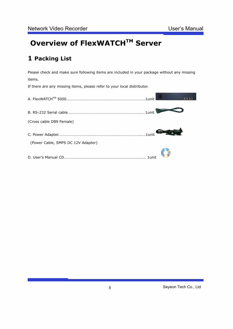
1 Packing List
Please check and make sure following items are included in your package without any missing
items.
If there are any missing items, please refer to your local distributor.
A. FlexWATCHTM 5000..…………………………………………………………………….1unit
B. RS-232 Serial cable…………………………………………………………………..…1unit
(Cross cable DB9 Female)
C. Power Adapter…………………………………………………………………………..….1unit
(Power Cable, SMPS DC 12V Adapter)
D. User’s Manual CD………………………………………………………….……………… 1unit
Network Video Recorder User’s Manual
Seyeon Tech Co., Ltd
9
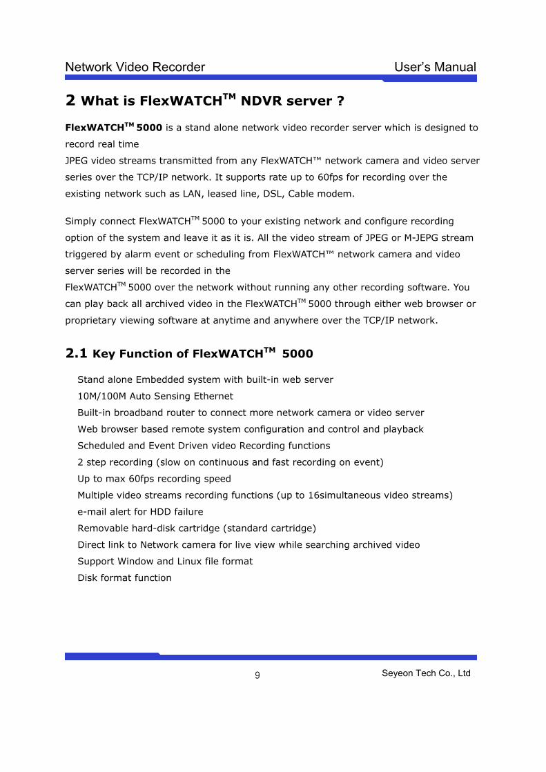
2 What is FlexWATCHTM NDVR server ?
FlexWATCHTM 5000 is a stand alone network video recorder server which is designed to
record real time
JPEG video streams transmitted from any FlexWATCH™ network camera and video server
series over the TCP/IP network. It supports rate up to 60fps for recording over the
existing network such as LAN, leased line, DSL, Cable modem.
Simply connect FlexWATCHTM 5000 to your existing network and configure recording
option of the system and leave it as it is. All the video stream of JPEG or M-JEPG stream
triggered by alarm event or scheduling from FlexWATCH™ network camera and video
server series will be recorded in the
FlexWATCHTM 5000 over the network without running any other recording software. You
can play back all archived video in the FlexWATCHTM 5000 through either web browser or
proprietary viewing software at anytime and anywhere over the TCP/IP network.
2.1 Key Function of FlexWATCHTM 5000
� Stand alone Embedded system with built-in web server
� 10M/100M Auto Sensing Ethernet
� Built-in broadband router to connect more network camera or video server
� Web browser based remote system configuration and control and playback
� Scheduled and Event Driven video Recording functions
� 2 step recording (slow on continuous and fast recording on event)
� Up to max 60fps recording speed
� Multiple video streams recording functions (up to 16simultaneous video streams)
� e-mail alert for HDD failure
� Removable hard-disk cartridge (standard cartridge)
� Direct link to Network camera for live view while searching archived video
� Support Window and Linux file format
� Disk format function
Network Video Recorder User’s Manual
Seyeon Tech Co., Ltd
10
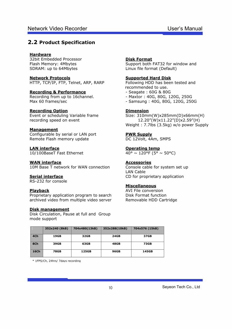
2.2 Product Specification Hardware 32bit Embedded Processor Flash Memory: 4Mbytes SDRAM: up to 64Mbytes Network Protocols HTTP, TCP/IP, FTP, Telnet, ARP, RARP Recording & Performance Recording from up to 16channel. Max 60 frames/sec Recording Option Event or scheduling Variable frame recording speed on event Management Configurable by serial or LAN port Remote Flash memory update LAN interface 10/100BaseT Fast Ethernet WAN interface 10M Base T network for WAN connection Serial interface RS-232 for console
Playback Proprietary application program to search archived video from multiple video server
Disk management Disk Circulation, Pause at full and Group mode support
Disk Format Support both FAT32 for window and Linux file format (Default) Supported Hard Disk Following HDD has been tested and recommended to use. - Seagate : 60G & 80G - Maxtor : 40G, 80G, 120G, 250G - Samsung : 40G, 80G, 120G, 250G Dimension Size: 310mm(W)x285mm(D)x66mm(H) 12.20”(W)x11.22”(D)x2.59”(H) Weight : 7.7lbs (3.5kg) w/o power Supply PWR Supply DC 12Volt, 4Am, SMPS Operating temp 40° ~ 120°F (5° ~ 50°C) Accessories Console cable for system set up LAN Cable CD for proprietary application Miscellaneous AVI File conversion Disk Format function Removable HDD Cartridge
352x240 (8kB) 704x480(13kB) 352x288(10kB) 704x576 (15kB)
4Ch 19GB 32GB 24GB 37GB
8Ch 39GB 63GB 48GB 73GB
16Ch 78GB 125GB 96GB 145GB
* 1FPS/Ch, 24hrs/ 7days recording
Network Video Recorder User’s Manual
Seyeon Tech Co., Ltd
11
2.3 Application FW-5000 is born to secure on-site video recording over the TCP/IP network satisfying the
need for reliable, flexible and distributed on-site video recording in the TCP/IP based
remote video surveillance industry.
By combining with FlexWATCHTM network Camera or video server series, following can be
suggested application area.
· Chain store, Franchised restaurant
· Distributed video recording for local facility
· Remote branch office monitoring
· Plant, Oil refinery, Power sub_station
· Globally presented branch office monitoring
· Parking Lots, warehouse, Gas Station
Network Video Recorder User’s Manual
Seyeon Tech Co., Ltd
12
Hardware Description • This chapter contains list of items to be prepared for the installation of FlexWATCHTM
NVR server.
• Please carefully read this chapter before the installation.
• Please prepare all the necessary items before start installation to prevent any possible
malfunction or any other hazard can be happened during the installation.
1.1 Caution and observance • Keep the device in the clean and dried area where air ventilation is guaranteed. The
device is not waterproof. The waterproof device or similar device must protect from any
possible hazard by water or heavy moisture etc.
• Regulated power supply is prerequisite for stable and optimal operation of the device.
Use only power supply (SMPS 12V 4Am) supplied with FlexWATCHTM NVR server.
Manufacturer shall not liable for any hazard or shock caused by use of any other power
supply.
• To prevent risk of electric shock, do not remove system-case. No user serviceable parts
inside. Any repair or modification for the product will be allowed to qualified service
personal only
• Use the cable supplied with FlexWATCHTM NVR server. If you need to connect
FlexWATCHTM NVR server to the other device (External Modem, PTZ device), power on
the devices before connect to the FlexWATCHTM NVR server.
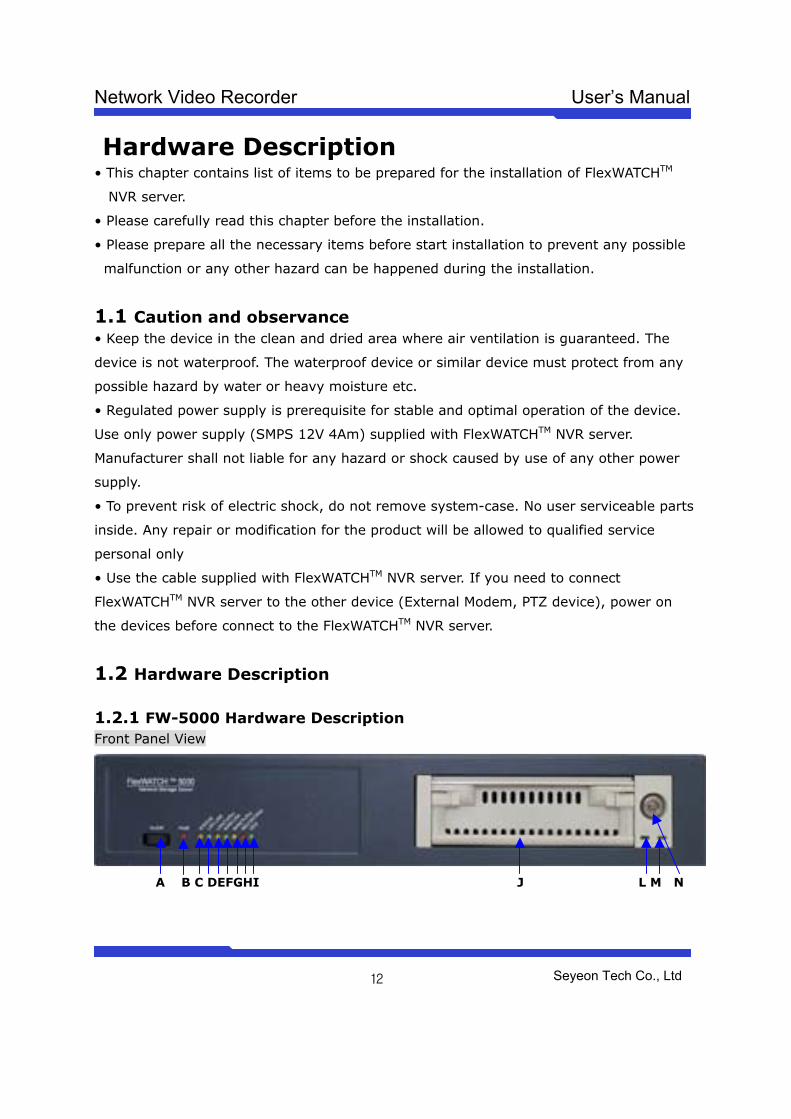
1.2 Hardware Description
1.2.1 FW-5000 Hardware Description Front Panel View
A B C DEFGHI J L M N
Network Video Recorder User’s Manual
Seyeon Tech Co., Ltd
13
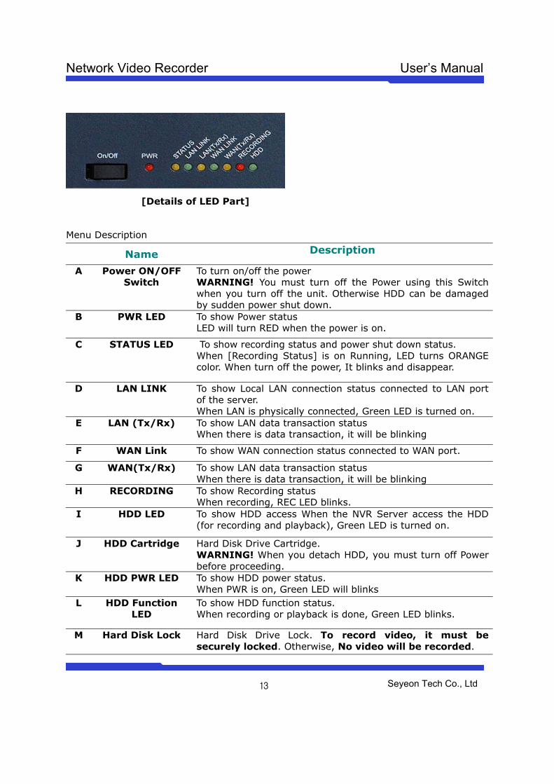
[Details of LED Part]
Menu Description
Name Description
A Power ON/OFF Switch
To turn on/off the power WARNING! You must turn off the Power using this Switch when you turn off the unit. Otherwise HDD can be damaged by sudden power shut down.
B PWR LED To show Power status LED will turn RED when the power is on.
C STATUS LED To show recording status and power shut down status. When [Recording Status] is on Running, LED turns ORANGE color. When turn off the power, It blinks and disappear.
D LAN LINK To show Local LAN connection status connected to LAN port of the server. When LAN is physically connected, Green LED is turned on.
E LAN (Tx/Rx) To show LAN data transaction status When there is data transaction, it will be blinking
F WAN Link To show WAN connection status connected to WAN port.
G WAN(Tx/Rx) To show LAN data transaction status When there is data transaction, it will be blinking
H RECORDING To show Recording status When recording, REC LED blinks.
I HDD LED To show HDD access When the NVR Server access the HDD (for recording and playback), Green LED is turned on.
J HDD Cartridge Hard Disk Drive Cartridge. WARNING! When you detach HDD, you must turn off Power before proceeding.
K HDD PWR LED To show HDD power status. When PWR is on, Green LED will blinks
L HDD Function LED
To show HDD function status. When recording or playback is done, Green LED blinks.
M Hard Disk Lock Hard Disk Drive Lock. To record video, it must be securely locked. Otherwise, No video will be recorded.
Network Video Recorder User’s Manual
Seyeon Tech Co., Ltd
14
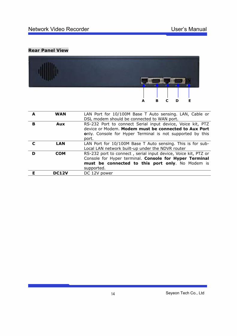
Rear Panel View
A B C D E
A WAN LAN Port for 10/100M Base T Auto sensing. LAN, Cable or DSL modem should be connected to WAN port.
B Aux RS-232 Port to connect Serial input device, Voice kit, PTZ device or Modem. Modem must be connected to Aux Port only. Console for Hyper Terminal is not supported by this port.
C LAN LAN Port for 10/100M Base T Auto sensing. This is for sub- Local LAN network built-up under the NDVR router
D COM RS-232 port to connect , serial input device, Voice kit, PTZ or Console for Hyper terminal. Console for Hyper Terminal must be connected to this port only. No Modem is supported.
E DC12V DC 12V power
Network Video Recorder User’s Manual
Seyeon Tech Co., Ltd
15
IP assignment
1 Key Words for Network LAN (Local Area Network) : Under the LAN network, any network device in the same
LAN network can be accessed by any other network device. But LAN network can not be
accessed from the Internet (WAN).
Most of case, LAN is built after Router which is connected to WAN network so that
Network device in the local area network can access to the Internet through Router. Most
of case, LAN networked device can not be accessed from the Internet (WAN), unless it is
not configured to be accessed from the Internet through NAT function of router.
WAN (Wide Area Network) : WAN enables all network device can be accessed by each
other over the Internet. It included Leased Line, Cable modem, xDSL, ISDN and
Telephone line etc.
IP address : IP address is abbreviation of Internet Protocol address which allows all
network devices can communicate other over the network using Internet protocol. Each
network device has its own unit IP address whether or not it is in the LAN or WAN
network. Therefore network devices can be accessed by other network device from either
LAN or WAN (Internet).
For example, www.yahoo.com is a web server which has its own IP address so that any
body can has access to Yahoo web site. Like most of public web site has its own IP
address. Although IP address can not be seen by the client, domain name
(www.yahoo.com) is automatically converted into IP address by DNS server.
Static IP address : A static IP address is an IP address permanently assigned to
computer or network devices in a TCP/IP network. Static IP address is usually assigned
to network devices which are consistently accessed by any users. For instances,
www.yahoo.com has global static IP address. Thus, any body can access to the site. If
you want to view live video stream from FlexWATCHTM server over the Internet, you need
to assign Global Static IP address.
Depending the network Public Static IP(WAN) or Private Static IP can be assigned to
network device.
Dynamic IP address : A dynamic IP address is an IP address that is automatically
Network Video Recorder User’s Manual
Seyeon Tech Co., Ltd
16
assigned to a client station (computer, network equipment, etc.) in a TCP/IP network.
Dynamic IP address is typically assigned by a DHCP server, which can be a computer on
the network or another piece of hardware, such as router. A dynamic IP address may
change every time your computer connects to the network
DHCP (Dynamic Host Configuration Protocol) : DHCP is software that automatically
assigns IP addresses to client stations logging onto a TCP/IP network. DCHP eliminates
troublesome job to manually assign permanent IP addresses to every device on your
network. DHCP software typically runs in servers and is also found in network devices
such as routers. Most of Cable Modem for Internet access uses DHCP Public IP address
and Private IP address : Public IP address is an IP address which can be identified
uniquely in Internet world. All IP addresses excluding private IP addresses are public IP
addresses. Private IP addresses range from 10.0.0.0 until 10.255.255.255, and from
192.168.0.0 to 192.168.255.255. Generally speaking, private IP addresses are used in
local area network which are hidden from the Internet world. Also, when public IP
addresses not enough, private IP addresses are used while sharing global IP addresses
Router : Router is a network hardware which routes either Private or Public IP address
to Public network so that network device between private IP network and Public IP
network can communicate over the network. Router has NAT (Network Address
Translation) function and through this function Public IP address will be mapped into
private IP network so that Network device in the private IP address can be added from
Internet.
Hub : Hub is a hardware which relay transmission between Router and Network device.
There are two types of Hub. One is Dummy hub and the other one is Switching hub. Note
that Hub will be used in the local network only.
NAT (Network Address Translation) : Network Address Translation (NAT) translates
multiple IP addressed on the private LAN to one public address that is sent out to the
Internet. This adds a level of security since the address of a PC connected to the private
LAN is never transmitted on the Internet.
Network Video Recorder User’s Manual
Seyeon Tech Co., Ltd
17
AOIP (Always On Internet Protocol) Server: AOIP™ server (Always On IP) is run by
Seyeon Technology or its business partner and is a gateway for remote users to access
FlexWATCH™ servers which is connected dynamic IP address over DSL,Cable modem and
PSTN network over the Internet. FlexWATCH™ Network Video Server and Camera Server
family is fully supported by AOIP server and any type of IP address(Global Dynamic IP or
Private IP) can be assigned to FlexWATCHTM server and user can access FlexWATCH™
system from the Internet at anytime and anywhere through AOIP server.
2 Check Points before IP assignment Following are list of item to be checked before you start configuration of
FlexWATCHTM server.
2.1 IP address You need to have Static IP address and other information such as Default Gateway and
Network Mask which are to be assigned to FlexWATCHTM server. Please consult with your
network administrator, if FlexWATCHTM server is to be installed in your corporate network,
or consult with ISP if you want to install it in your home or shop for which DSL or Cable
modem Internet service is available.
Following could be a simple way of finding IP address information of your PC and with
that information you can set up IP address to FlexWATCHTM server in the private IP
network without consulting to your ISP.
- Open DOS Command window as following procedure.
Program> Accessories > DOS Prompt
- Enter ‘ ipconfig’ command. Following information will come up
2.1.1 Static IP address enabled PC (DHCP Disabled PC) You can easily check whether Static IP address is assigned to your PC. If you are in the
Static IP network, it is simpler to assign IP address to FlexWATCHTM server than DHCP
network.
Network Video Recorder User’s Manual
Seyeon Tech Co., Ltd
18
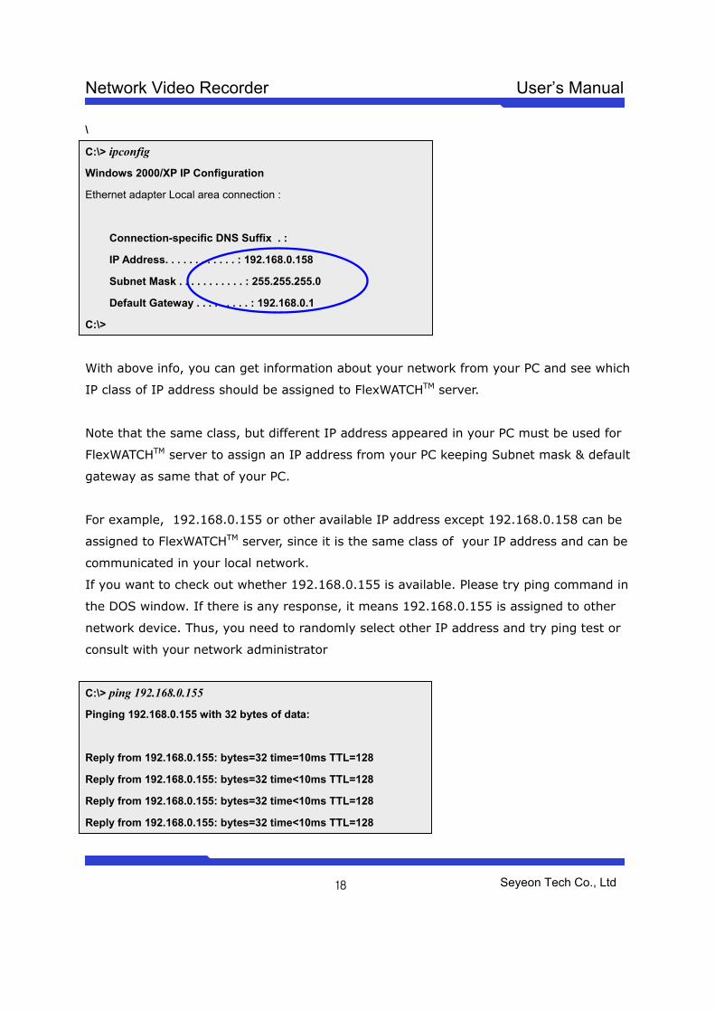
\
C:\> ipconfig
Windows 2000/XP IP Configuration
Ethernet adapter Local area connection :
Connection-specific DNS Suffix . :
IP Address. . . . . . . . . . . . : 192.168.0.158
Subnet Mask . . . . . . . . . . . : 255.255.255.0
Default Gateway . . . . . . . . . : 192.168.0.1
C:\>
With above info, you can get information about your network from your PC and see which
IP class of IP address should be assigned to FlexWATCHTM server.
Note that the same class, but different IP address appeared in your PC must be used for
FlexWATCHTM server to assign an IP address from your PC keeping Subnet mask & default
gateway as same that of your PC.
For example, 192.168.0.155 or other available IP address except 192.168.0.158 can be
assigned to FlexWATCHTM server, since it is the same class of your IP address and can be
communicated in your local network.
If you want to check out whether 192.168.0.155 is available. Please try ping command in
the DOS window. If there is any response, it means 192.168.0.155 is assigned to other
network device. Thus, you need to randomly select other IP address and try ping test or
consult with your network administrator
C:\> ping 192.168.0.155
Pinging 192.168.0.155 with 32 bytes of data:
Reply from 192.168.0.155: bytes=32 time=10ms TTL=128
Reply from 192.168.0.155: bytes=32 time<10ms TTL=128
Reply from 192.168.0.155: bytes=32 time<10ms TTL=128
Reply from 192.168.0.155: bytes=32 time<10ms TTL=128
Network Video Recorder User’s Manual
Seyeon Tech Co., Ltd
19
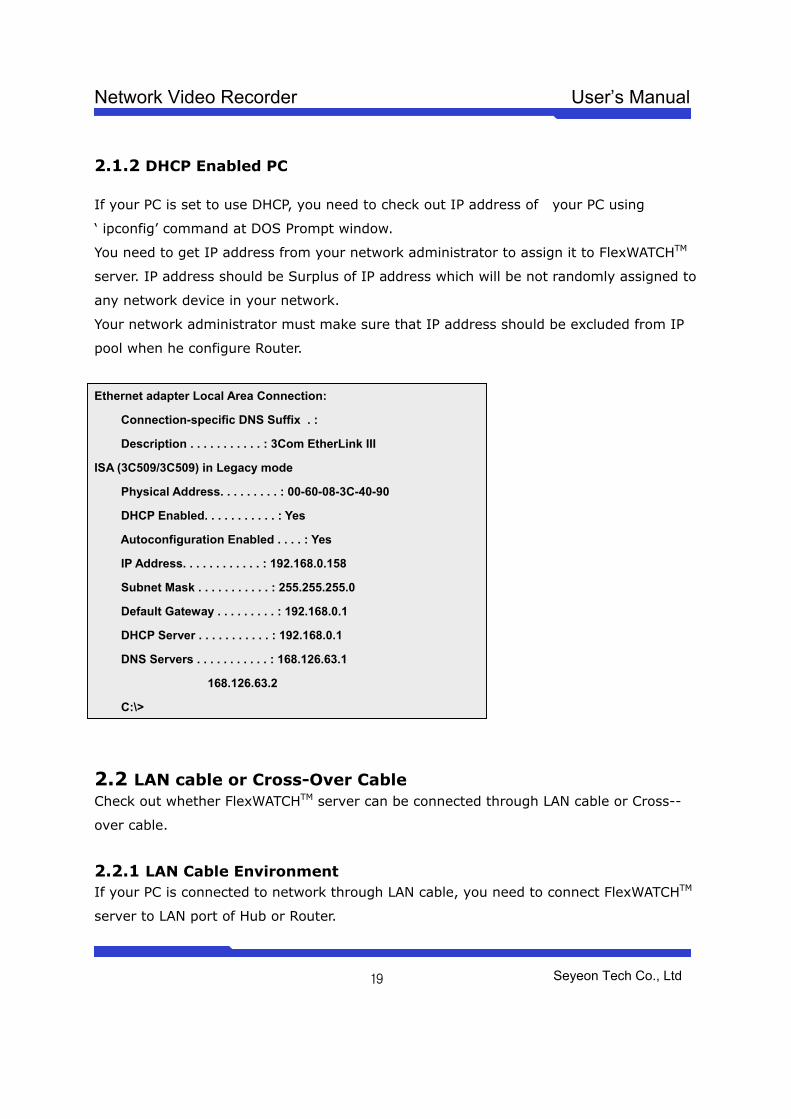
2.1.2 DHCP Enabled PC If your PC is set to use DHCP, you need to check out IP address of your PC using
‘ ipconfig’ command at DOS Prompt window.
You need to get IP address from your network administrator to assign it to FlexWATCHTM
server. IP address should be Surplus of IP address which will be not randomly assigned to
any network device in your network.
Your network administrator must make sure that IP address should be excluded from IP
pool when he configure Router.
Ethernet adapter Local Area Connection:
Connection-specific DNS Suffix . :
Description . . . . . . . . . . . : 3Com EtherLink III
ISA (3C509/3C509) in Legacy mode
Physical Address. . . . . . . . . : 00-60-08-3C-40-90
DHCP Enabled. . . . . . . . . . . : Yes
Autoconfiguration Enabled . . . . : Yes
IP Address. . . . . . . . . . . . : 192.168.0.158
Subnet Mask . . . . . . . . . . . : 255.255.255.0
Default Gateway . . . . . . . . . : 192.168.0.1
DHCP Server . . . . . . . . . . . : 192.168.0.1
DNS Servers . . . . . . . . . . . : 168.126.63.1
168.126.63.2
C:\>
2.2 LAN cable or Cross-Over Cable Check out whether FlexWATCHTM server can be connected through LAN cable or Cross--
over cable.
2.2.1 LAN Cable Environment If your PC is connected to network through LAN cable, you need to connect FlexWATCHTM
server to LAN port of Hub or Router.
Network Video Recorder User’s Manual
Seyeon Tech Co., Ltd
20
2.2.2 Cross-over cable If LAN network is not available, you can directly connect FlexWATCHTM server to your PC
through Cross-over cable. In this case, you need to prepare Cross-over cable separately
(Note that The LAN cable included in the product package is not Cross-over cable, but
normal straight cable) and you need to set your PC IP address as 10.20.30.41 and
connect the server with Factory default IP address, 10.20.30.40 through web browser.
Following is brief procedure to connect the server after changing PC IP address.
1) Click right button of your mouse on the ‘My Network Places’ icon in the main screen
window.
2) Click right button of your mouse on the ‘Local area connection’ icon and select
‘Property’ option.
3) Select ‘Internet protocol (TCP/IP)’ option and click ‘Property’ icon.
4) Select ‘use the following IP address’ option from the TCP/IP property option and set
the IP address as follow
- IP address : 10.20.30.41
- Network Mask : 255.255.255.0
5) Connect FlexWATCHTM server using Cross-over cable to your PC and run your web
browser and enter default IP address, 10.20.30.40 of FlexWATCHTM server in the URL
field. Note that Cross-over cable is not supplied with product.
6) Once you are connected to the server, click Admin icon and click LAN configuration
menu.
7) Enter IP address you would like to assign to the FlexWATCHTM server and change your
PC IP address again.
2.3 PC Environment Check out whether your PC is connected to LAN or WAN network or stand-alone. If stand
alone, you need to use Cross-over cable or build up LAN environment to use LAN cable.
Network Video Recorder User’s Manual
Seyeon Tech Co., Ltd
21
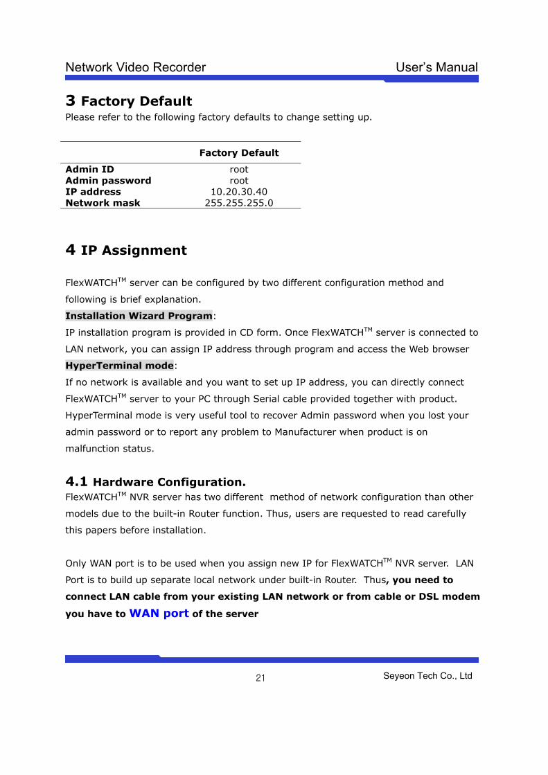
3 Factory Default Please refer to the following factory defaults to change setting up.
Factory Default
Admin ID root Admin password root IP address 10.20.30.40 Network mask 255.255.255.0
4 IP Assignment
FlexWATCHTM server can be configured by two different configuration method and
following is brief explanation.
Installation Wizard Program:
IP installation program is provided in CD form. Once FlexWATCHTM server is connected to
LAN network, you can assign IP address through program and access the Web browser
HyperTerminal mode:
If no network is available and you want to set up IP address, you can directly connect
FlexWATCHTM server to your PC through Serial cable provided together with product.
HyperTerminal mode is very useful tool to recover Admin password when you lost your
admin password or to report any problem to Manufacturer when product is on
malfunction status.
4.1 Hardware Configuration. FlexWATCHTM NVR server has two different method of network configuration than other
models due to the built-in Router function. Thus, users are requested to read carefully
this papers before installation.
Only WAN port is to be used when you assign new IP for FlexWATCHTM NVR server. LAN
Port is to build up separate local network under built-in Router. Thus, you need to
connect LAN cable from your existing LAN network or from cable or DSL modem
you have to WAN port of the server
Network Video Recorder User’s Manual
Seyeon Tech Co., Ltd
22
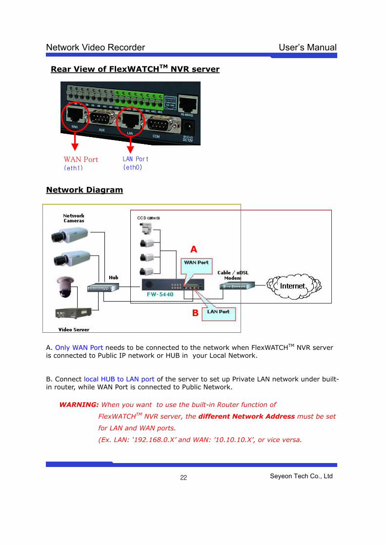
Rear View of FlexWATCHTM NVR server
Network Diagram
A. Only WAN Port needs to be connected to the network when FlexWATCHTM NVR server is connected to Public IP network or HUB in your Local Network.
B. Connect local HUB to LAN port of the server to set up Private LAN network under built-in router, while WAN Port is connected to Public Network.
WARNING: When you want to use the built-in Router function of
FlexWATCHTM NVR server, the different Network Address must be set
for LAN and WAN ports.
(Ex. LAN: ‘192.168.0.X’ and WAN: ’10.10.10.X’, or vice versa.
WAN Port (eth1)
LAN Port
(eth0)
A
B
Network Video Recorder User’s Manual
Seyeon Tech Co., Ltd
23
4.2 Through Installation Wizard Program IP setting with Installation Wizard program is easy and simple way and after IP setting is
done you can do other configuration through web browser.
You can use IP Installation Wizard Program through following step.
(IPInstallationWizard.exe is provide in the product CD)
1) Connect FlexWATCHTM NVR server (WAN port) into the network (Hub) that your PC is
belong to.
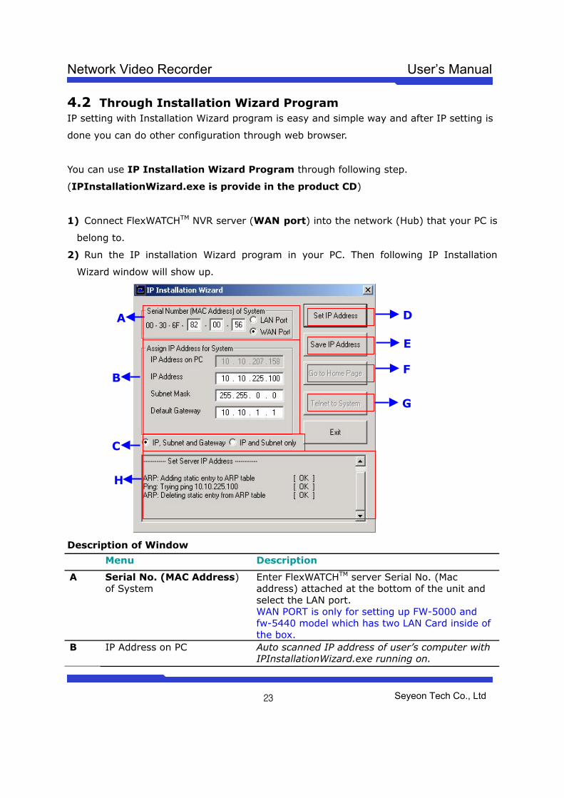
2) Run the IP installation Wizard program in your PC. Then following IP Installation
Wizard window will show up.
Description of Window
Menu Description
A Serial No. (MAC Address) of System
Enter FlexWATCHTM server Serial No. (Mac address) attached at the bottom of the unit and select the LAN port. WAN PORT is only for setting up FW-5000 and fw-5440 model which has two LAN Card inside of the box.
B IP Address on PC Auto scanned IP address of user’s computer with IPInstallationWizard.exe running on.
A
B
C
H
D
E
F
G
Network Video Recorder User’s Manual
Seyeon Tech Co., Ltd
24
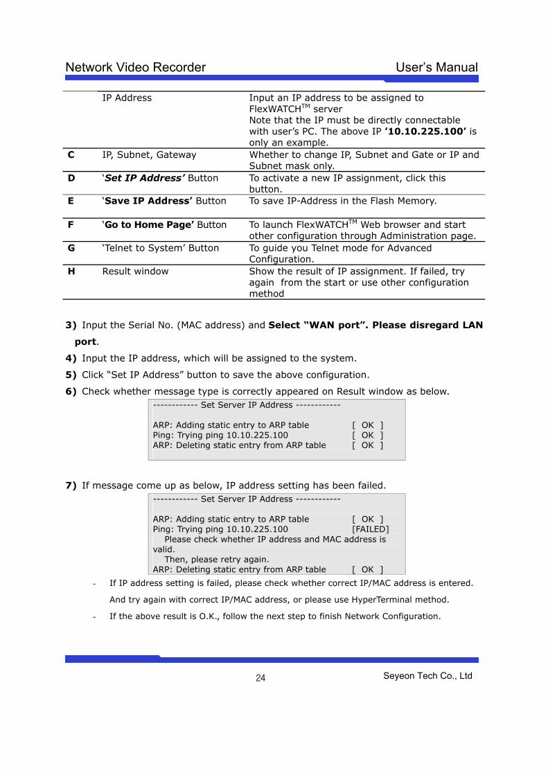
IP Address Input an IP address to be assigned to FlexWATCHTM server Note that the IP must be directly connectable with user’s PC. The above IP ’10.10.225.100’ is only an example.
C IP, Subnet, Gateway Whether to change IP, Subnet and Gate or IP and Subnet mask only.
D
‘Set IP Address’ Button To activate a new IP assignment, click this button.
E ‘Save IP Address’ Button To save IP-Address in the Flash Memory.
F ‘Go to Home Page’ Button To launch FlexWATCHTM Web browser and start other configuration through Administration page.
G ‘Telnet to System’ Button To guide you Telnet mode for Advanced Configuration.
H Result window Show the result of IP assignment. If failed, try again from the start or use other configuration method
3) Input the Serial No. (MAC address) and Select “WAN port”. Please disregard LAN
port.
4) Input the IP address, which will be assigned to the system.
5) Click “Set IP Address” button to save the above configuration.
6) Check whether message type is correctly appeared on Result window as below. ------------ Set Server IP Address ------------ ARP: Adding static entry to ARP table [ OK ] Ping: Trying ping 10.10.225.100 [ OK ] ARP: Deleting static entry from ARP table [ OK ]
7) If message come up as below, IP address setting has been failed. ------------ Set Server IP Address ------------ ARP: Adding static entry to ARP table [ OK ] Ping: Trying ping 10.10.225.100 [FAILED] Please check whether IP address and MAC address is valid. Then, please retry again. ARP: Deleting static entry from ARP table [ OK ]
- If IP address setting is failed, please check whether correct IP/MAC address is entered.
And try again with correct IP/MAC address, or please use HyperTerminal method.
- If the above result is O.K., follow the next step to finish Network Configuration.
Network Video Recorder User’s Manual
Seyeon Tech Co., Ltd
25
8) Click “Save IP Address” button to save IP-Address in the Flash Memory.
9) Click “Go to Home Page” button to access to FlexWATCHTM Web browser.
10) For server configuration, click “Admin” Icon and Input User ID and Password
(Factory default is root : root) to get into configuration mode and then press “OK”
button.
Note
Once you changed the IP address of FlexWATCHTM NVR server, you need to connect the
server with the changed IP address. If you lost the IP address assigned to FlexWATCHTM
NVR server, you need to set-up a new IP address again.
Note
If IP address set result is failed, please check whether correct IP/MAC address is entered.
And try again with correct IP/MAC address, or please use HyperTerminal method.
4.3 IP Assignment through Hyper Terminal mode Microsoft Windows provides Terminal emulation program, namely Hyper Terminal. For
HyperTerminal connection, Power, RS-232 Cable and LAN cable must be connected to
FlexWATCHTM server with user’s PC. LAN cable is to run Web browser after configuration
using HyperTerminal. You can continue below configuration after Network setting, and the
next process will be same as using Installation Wizard Program.
1) Link up with the provided serial cable between COM port at FW-5440 and COM1 or
COM2 at user’s PC.
2) Run Hyper Terminal Program on user’s PC.
Window start> Program> Accessory> Communication> Hyper Terminal
Network Video Recorder User’s Manual
Seyeon Tech Co., Ltd
26
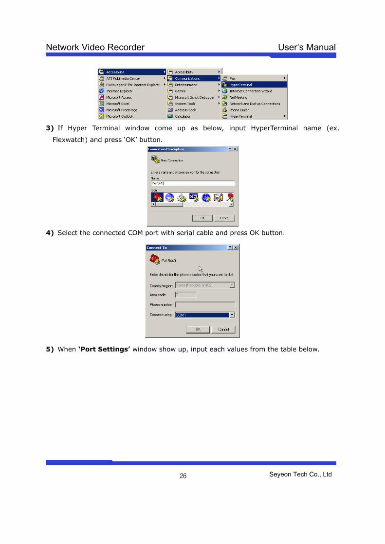
3) If Hyper Terminal window come up as below, input HyperTerminal name (ex.
Flexwatch) and press ‘OK’ button.
4) Select the connected COM port with serial cable and press OK button.
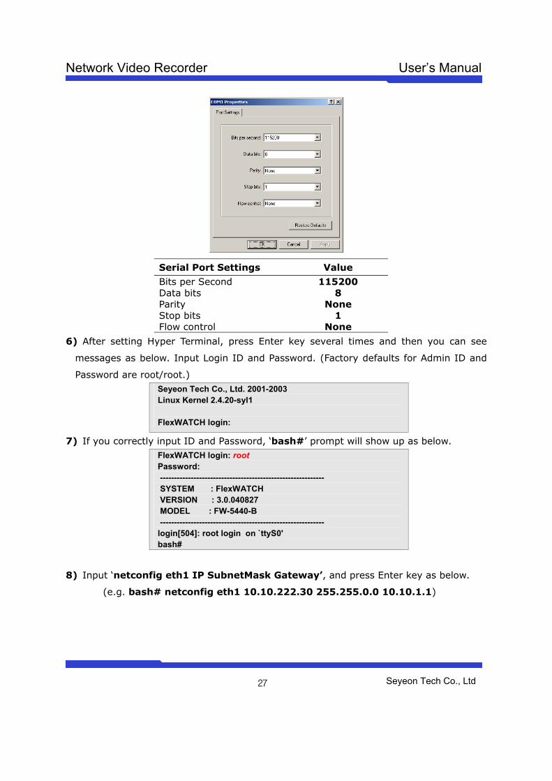
5) When ‘Port Settings’ window show up, input each values from the table below.
Network Video Recorder User’s Manual
Seyeon Tech Co., Ltd
27
Serial Port Settings Value
Bits per Second 115200 Data bits 8 Parity None Stop bits 1 Flow control None
6) After setting Hyper Terminal, press Enter key several times and then you can see
messages as below. Input Login ID and Password. (Factory defaults for Admin ID and
Password are root/root.) Seyeon Tech Co., Ltd. 2001-2003 Linux Kernel 2.4.20-syl1 FlexWATCH login:
7) If you correctly input ID and Password, ‘bash#’ prompt will show up as below. FlexWATCH login: root Password: ----------------------------------------------------------- SYSTEM : FlexWATCH VERSION : 3.0.040827 MODEL : FW-5440-B ----------------------------------------------------------- login[504]: root login on `ttyS0' bash#
8) Input ‘netconfig eth1 IP SubnetMask Gateway’, and press Enter key as below.
(e.g. bash# netconfig eth1 10.10.222.30 255.255.0.0 10.10.1.1)
Network Video Recorder User’s Manual
Seyeon Tech Co., Ltd
28
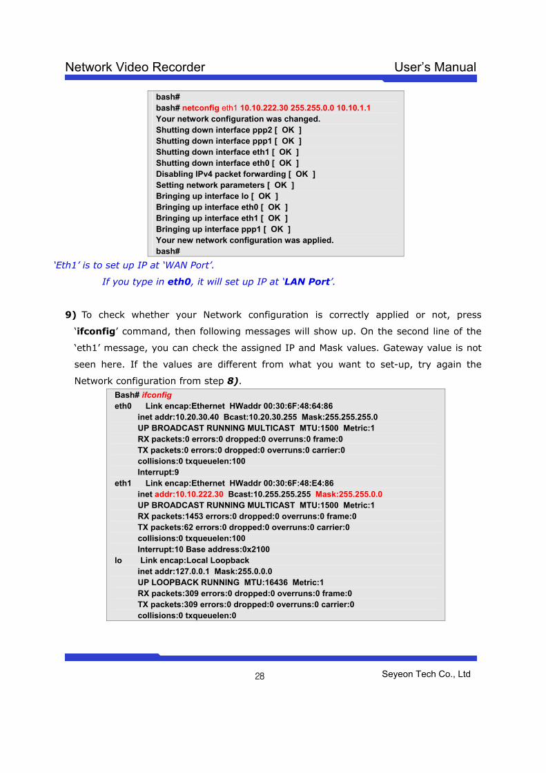
bash# bash# netconfig eth1 10.10.222.30 255.255.0.0 10.10.1.1 Your network configuration was changed. Shutting down interface ppp2 [ OK ] Shutting down interface ppp1 [ OK ] Shutting down interface eth1 [ OK ] Shutting down interface eth0 [ OK ] Disabling IPv4 packet forwarding [ OK ] Setting network parameters [ OK ] Bringing up interface lo [ OK ] Bringing up interface eth0 [ OK ] Bringing up interface eth1 [ OK ] Bringing up interface ppp1 [ OK ] Your new network configuration was applied. bash#
‘Eth1’ is to set up IP at ‘WAN Port’.
If you type in eth0, it will set up IP at ‘LAN Port’.
9) To check whether your Network configuration is correctly applied or not, press
‘ifconfig’ command, then following messages will show up. On the second line of the
‘eth1’ message, you can check the assigned IP and Mask values. Gateway value is not
seen here. If the values are different from what you want to set-up, try again the
Network configuration from step 8). Bash# ifconfig eth0 Link encap:Ethernet HWaddr 00:30:6F:48:64:86 inet addr:10.20.30.40 Bcast:10.20.30.255 Mask:255.255.255.0 UP BROADCAST RUNNING MULTICAST MTU:1500 Metric:1 RX packets:0 errors:0 dropped:0 overruns:0 frame:0 TX packets:0 errors:0 dropped:0 overruns:0 carrier:0 collisions:0 txqueuelen:100 Interrupt:9 eth1 Link encap:Ethernet HWaddr 00:30:6F:48:E4:86 inet addr:10.10.222.30 Bcast:10.255.255.255 Mask:255.255.0.0 UP BROADCAST RUNNING MULTICAST MTU:1500 Metric:1 RX packets:1453 errors:0 dropped:0 overruns:0 frame:0 TX packets:62 errors:0 dropped:0 overruns:0 carrier:0 collisions:0 txqueuelen:100 Interrupt:10 Base address:0x2100 lo Link encap:Local Loopback inet addr:127.0.0.1 Mask:255.0.0.0 UP LOOPBACK RUNNING MTU:16436 Metric:1 RX packets:309 errors:0 dropped:0 overruns:0 frame:0 TX packets:309 errors:0 dropped:0 overruns:0 carrier:0 collisions:0 txqueuelen:0
Network Video Recorder User’s Manual
Seyeon Tech Co., Ltd
29
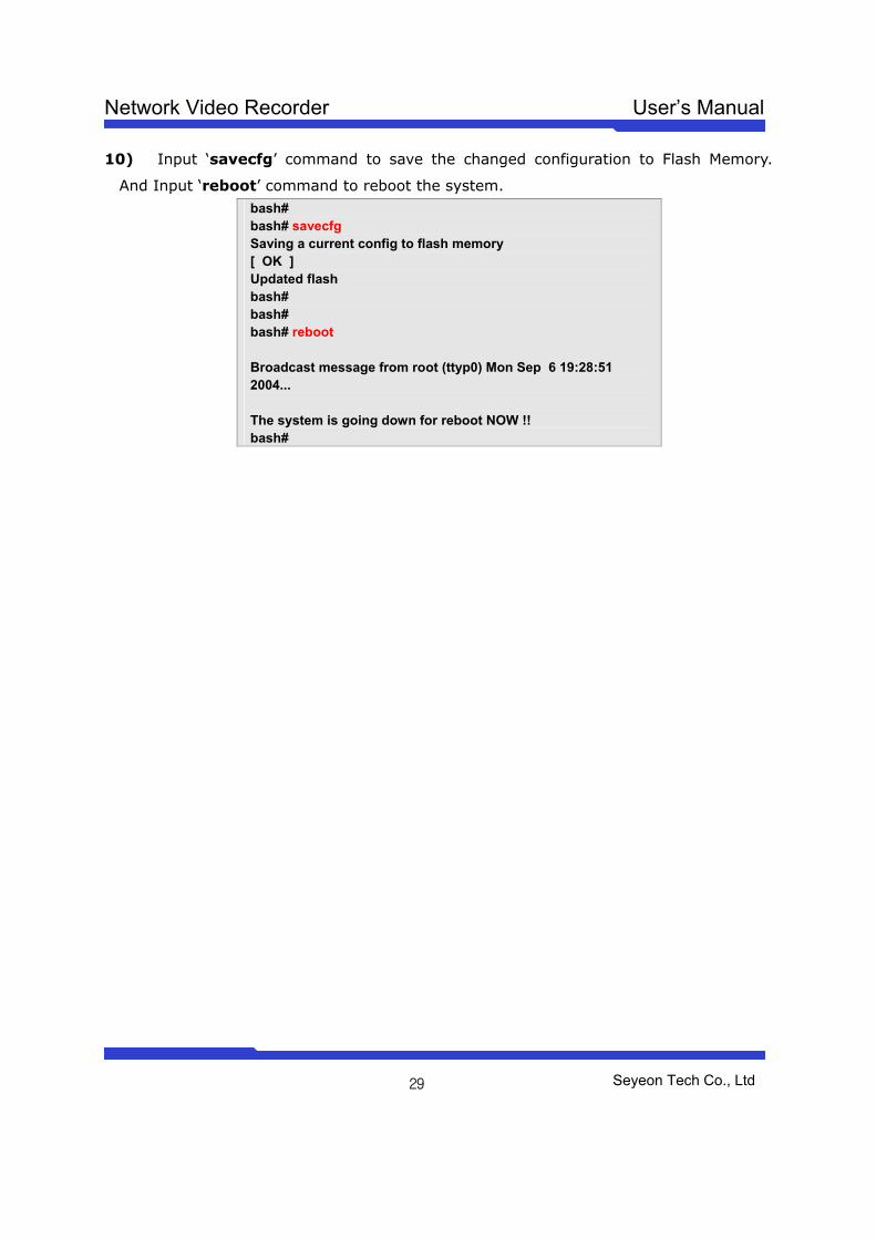
10) Input ‘savecfg’ command to save the changed configuration to Flash Memory.
And Input ‘reboot’ command to reboot the system. bash# bash# savecfg Saving a current config to flash memory [ OK ] Updated flash bash# bash# bash# reboot Broadcast message from root (ttyp0) Mon Sep 6 19:28:51 2004... The system is going down for reboot NOW !! bash#
Network Video Recorder User’s Manual
Seyeon Tech Co., Ltd
30
Live view Once IP assignment is finished and external FlexWATCHTM network Camera or video
server is registered in the FW-5000 server, you can view live video from network camera
or video server through standard web browser such as MS Internet Explorer.
Note that to view live from external FlexWATCHTM network Camera or video
server, Rx Module registration must be done beforehand.
Live view for the external FlexWATCHTM network camera or video server registered in the
NVR server can be viewed through Microsoft Internet Explorer only.
Viewing mode Operation System Web browser Simple view (ActiveX) MS Window Internet explorer only
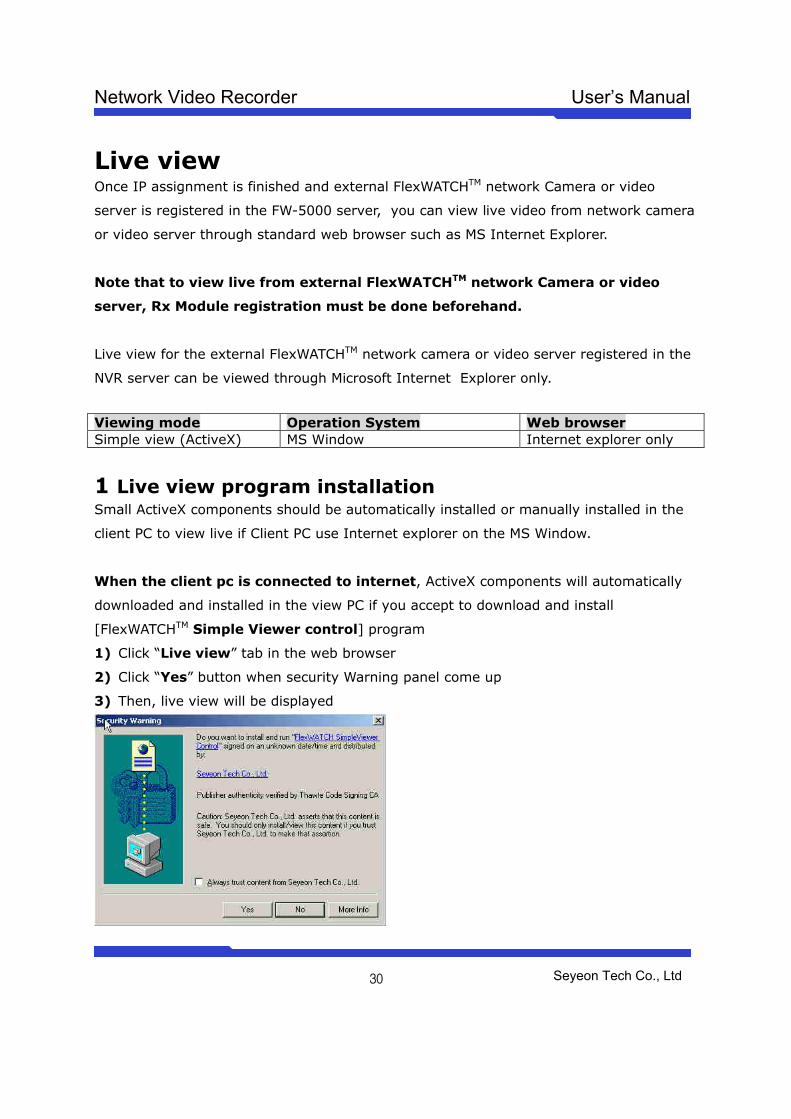
1 Live view program installation Small ActiveX components should be automatically installed or manually installed in the
client PC to view live if Client PC use Internet explorer on the MS Window.
When the client pc is connected to internet, ActiveX components will automatically
downloaded and installed in the view PC if you accept to download and install
[FlexWATCHTM Simple Viewer control] program
1) Click “Live view” tab in the web browser
2) Click “Yes” button when security Warning panel come up
3) Then, live view will be displayed
Network Video Recorder User’s Manual
Seyeon Tech Co., Ltd
31
When the Client pc is not connected to internet, you need to manually install ActiveX
components in your viewing PC.
- Insert the product CD in your PC
- Select “FlexWATCH Simple Viewer control” program
-
Application idea
ActiveX based SDK is provided for software developers so that application program
developers can easily utilize digital video from FlexWATCHTM server for his own video
application.
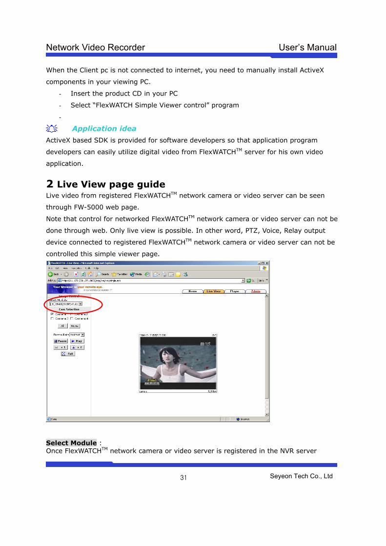
2 Live View page guide Live video from registered FlexWATCHTM network camera or video server can be seen
through FW-5000 web page.
Note that control for networked FlexWATCHTM network camera or video server can not be
done through web. Only live view is possible. In other word, PTZ, Voice, Relay output
device connected to registered FlexWATCHTM network camera or video server can not be
controlled this simple viewer page.
Select Module : Once FlexWATCHTM network camera or video server is registered in the NVR server
Network Video Recorder User’s Manual
Seyeon Tech Co., Ltd
32
through Rx Module registration process, list of server will be shown in the Selected module column as a Server module. Note that only cameras connected to the selected module can be displayed one at a time. Cam Control : By checking the camera you can get any number of camera displayed on the same screen. Camera 1, 2, 3, 4 and all cameras can be displayed together. Sequence : To view camera selected camera sequentially. Frame rate : You can adjust display frame rate by control Frame rate option Display size : X1 for Real size, x2 for double size and Full screen mode is supported.
Network Video Recorder User’s Manual
Seyeon Tech Co., Ltd
33
System Configuration System configuration is to set up basic functions which helps you properly run and
manage the system. It is highly recommended to set up the configuration before any
other configurations. Following functions are provided in the System configuration mode.
- System name and Info
- System Administration account set up
- System access level setting
- Serial port configuration (Modem or Console device connection)
- RX Module Registration
1 System Information System information is very important one
Following menu will be provided
Server Name User definable and Identifier of the system when the system is accessed by third party program such as NDVR software.
Serial Number Product serial number. This information must be submitted for RMA or Warranty claim
Model This information also needs to be submitted for technical support request
Version System firmware version. This information also needs to be submitted for technical support request
2 Date & Time Date & time is very important factor to trigger any service at the right time such as FTP,
e-Mail, Alarm notification etc. If Date & time is not correctly set up in the system,
any service which will be triggered by schedule will be not done correctly.
Also Server Date & time info will be displayed on the image. If you need to display
correct time, please set up more accurate time information.
2.1 Date & Time in the server clock Date & time can be set up in the real time clock built in the server. Simple set up Date &
Time info in the Date & Time configuration field.
1) Go to Date & Time setup menu in the System configuration section of Admin mode
2) Set the correct time and click “Apply” button
Network Video Recorder User’s Manual
Seyeon Tech Co., Ltd
34
2.2 Date & Time using NTP server If multiple servers are installed over the network and controlled by client program and
synchronized time info is required, use NTP(Network Time Protocol) option.
1) Go to [NTP setup] menu in the Network configuration section of Admin Mode
2) Type in NTP server name or use default NTP time server, ntp.ewha.net, if you do not
know any NTP time server available in your area.
Note
NTP time server provide exact time wherever it is located.
3) Enable the service and select Time Zone where the FlexWATCHTM server is
located (not user’s viewing pc area)
4) Type in NTP time server info.
3 Admin Password Setup System administration Menu is user definable. It is highly recommended to change
default Admin Password to prevent any unwanted server control by any other person.
Please note followings
A. Factory default admin ID is root and Password is root (Case sensitive)
B. Admin ID(root) is not user definable and unchanging
A. Only Admin Password is user definable
4 Access Control and User registration Access permission is to set up user account for the system access. Through this
configuration you can create multiple user account with different control authority for
each camera and edit or delete user account.
Following features are provided by this mode
A. Option to allow system access without system Login ID & PW
B. Channel based different user account creation
C. Different control authority for Video, PTZ, Audio, and relay output device
Network Video Recorder User’s Manual
Seyeon Tech Co., Ltd
35
control
4.1 Full Access To allow system access by anyone who know the IP address. PTZ, Audio and Relay
output device can be controlled by anyone. Thus, if security for video is important, it is
higher recommended to user limited access mode below
4.2 Limited Access and User registration This is to limit server access to the authorized user only. Through this mode, you can
create multi level access account for each camera, not system level, with different control
authority.
Once Limited Access option is selected, User registration should be followed to effectively
use Limited Access function.
Application Tips
If servers are accessed and controlled by third party application program and if
you want to give different control authority for each camera to different application
program, you can give different access and control authority for PTZ, Audio, Relay output
device control for specific camera by creating different User account in the server.
Following is step for Limited access account for each camera.
1) Select [Limited Access] option in the Access Permission menu
2) Click [Apply] button
3) Click [user registration] menu in the System configuration section of Admin window
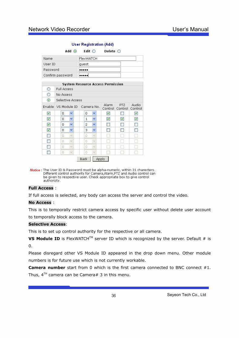
4) Fill out the column provided such as User name, ID & Password
5) Select the Camera module for which you would like to give permission and check
control item such as Alarm control, PTZ, and Audio control.
Note default VS Module ID is 0 and only Default VS Module ID is workable.
Network Video Recorder User’s Manual
Seyeon Tech Co., Ltd
36
Full Access :
If full access is selected, any body can access the server and control the video.
No Access :
This is to temporally restrict camera access by specific user without delete user account
to temporally block access to the camera.
Selective Access:
This is to set up control authority for the respective or all camera.
VS Module ID is FlexWATCHTM server ID which is recognized by the server. Default # is
0.
Please disregard other VS Module ID appeared in the drop down menu. Other module
numbers is for future use which is not currently workable.
Camera number start from 0 which is the first camera connected to BNC connect #1.
Thus, 4TH camera can be Camera# 3 in this menu.
Network Video Recorder User’s Manual
Seyeon Tech Co., Ltd
37
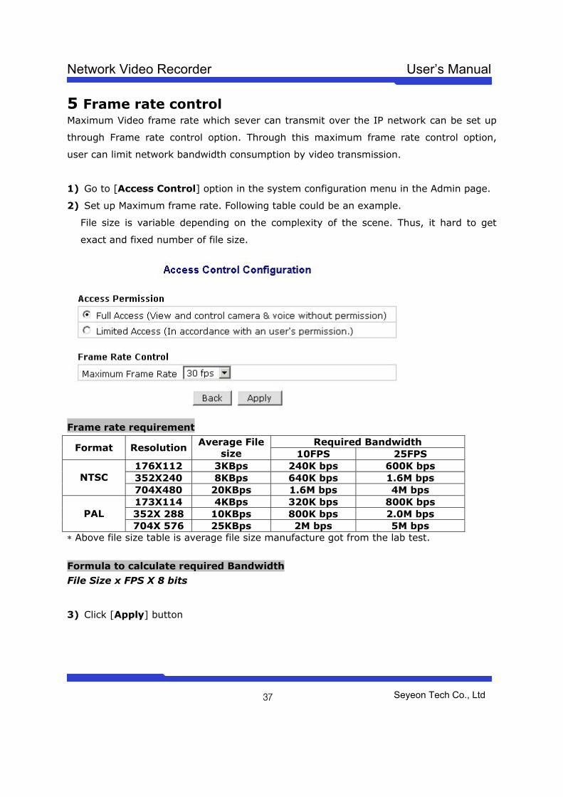
5 Frame rate control Maximum Video frame rate which sever can transmit over the IP network can be set up
through Frame rate control option. Through this maximum frame rate control option,
user can limit network bandwidth consumption by video transmission.
1) Go to [Access Control] option in the system configuration menu in the Admin page.
2) Set up Maximum frame rate. Following table could be an example.
File size is variable depending on the complexity of the scene. Thus, it hard to get
exact and fixed number of file size.
Frame rate requirement
Required Bandwidth Format Resolution
Average File size 10FPS 25FPS
176X112 3KBps 240K bps 600K bps 352X240 8KBps 640K bps 1.6M bps NTSC 704X480 20KBps 1.6M bps 4M bps 173X114 4KBps 320K bps 800K bps 352X 288 10KBps 800K bps 2.0M bps PAL 704X 576 25KBps 2M bps 5M bps
* Above file size table is average file size manufacture got from the lab test.
Formula to calculate required Bandwidth
File Size x FPS X 8 bits
3) Click [Apply] button
Network Video Recorder User’s Manual
Seyeon Tech Co., Ltd
38
6 Rx Module Registration
Video proxy function is supported by NDVR server such as FW-5440 and FW-5000
servers. By registering networked FlexWATCHTM network camera or video server into
NDVR server, video recording can be done in the NDVR server and live view can be
accessed through NDVR server web page which means user does not need to separately
run web browser to view live view from respective cameras from FlexWATCHTM video
servers.
Rx module registration is to set up the FlexWATCHTM server to communicate with FW-
5440 or FW-5000 NDVR server. When TX module is enabled at the FlexWATCHTM server,
RX module at NDVR server side should also be enabled as well.
6.1 Rx Module Connection type More than anything else connection type must be decided to set up the configuration.
Depending on which connection type is set up, TX module registration will be decided.
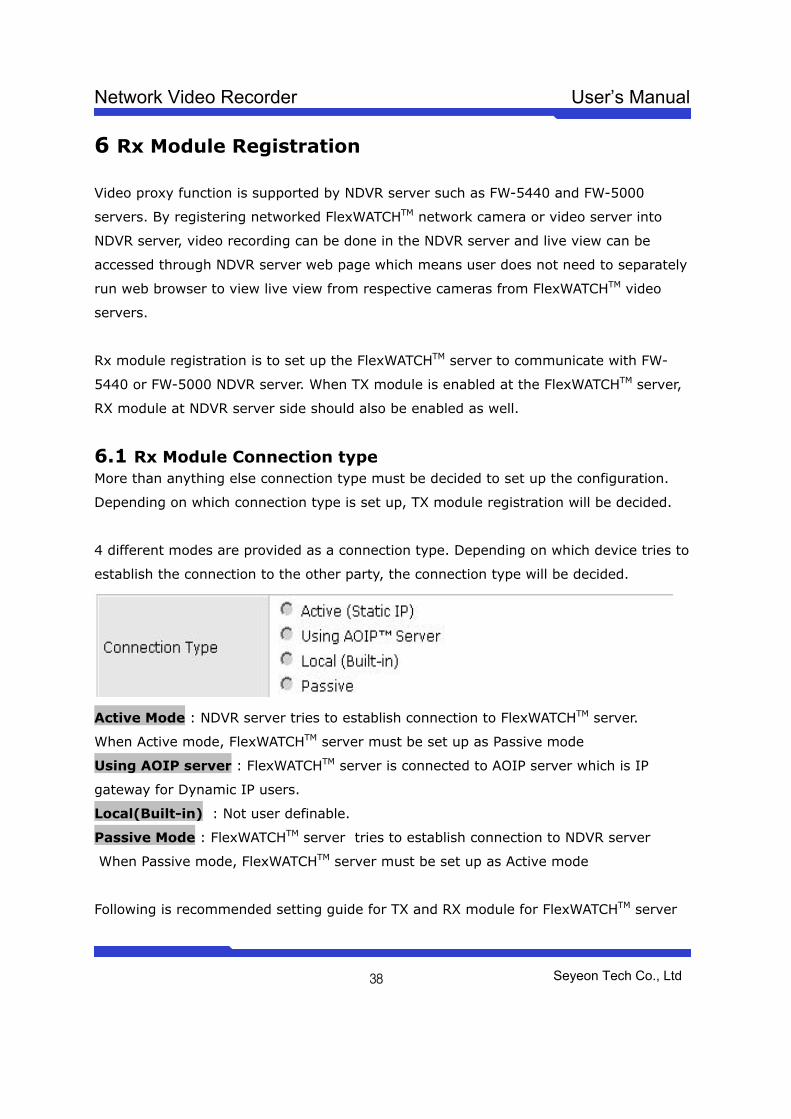
4 different modes are provided as a connection type. Depending on which device tries to
establish the connection to the other party, the connection type will be decided.
Active Mode : NDVR server tries to establish connection to FlexWATCHTM server.
When Active mode, FlexWATCHTM server must be set up as Passive mode
Using AOIP server : FlexWATCHTM server is connected to AOIP server which is IP
gateway for Dynamic IP users.
Local(Built-in) : Not user definable.
Passive Mode : FlexWATCHTM server tries to establish connection to NDVR server
When Passive mode, FlexWATCHTM server must be set up as Active mode
Following is recommended setting guide for TX and RX module for FlexWATCHTM server
Network Video Recorder User’s Manual
Seyeon Tech Co., Ltd
39
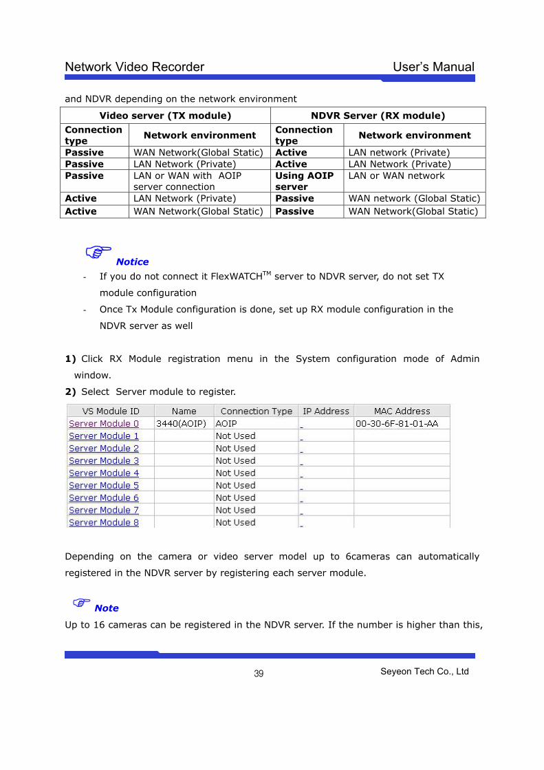
and NDVR depending on the network environment
Video server (TX module) NDVR Server (RX module)
Connection type
Network environment Connection type
Network environment
Passive WAN Network(Global Static) Active LAN network (Private) Passive LAN Network (Private) Active LAN Network (Private) Passive LAN or WAN with AOIP
server connection Using AOIP server
LAN or WAN network
Active LAN Network (Private) Passive WAN network (Global Static) Active WAN Network(Global Static) Passive WAN Network(Global Static)
Notice
- If you do not connect it FlexWATCHTM server to NDVR server, do not set TX
module configuration
- Once Tx Module configuration is done, set up RX module configuration in the
NDVR server as well
1) Click RX Module registration menu in the System configuration mode of Admin
window.
2) Select Server module to register.
Depending on the camera or video server model up to 6cameras can automatically
registered in the NDVR server by registering each server module.
Note
Up to 16 cameras can be registered in the NDVR server. If the number is higher than this,
Network Video Recorder User’s Manual
Seyeon Tech Co., Ltd
40
no performance stability can be guaranteed.
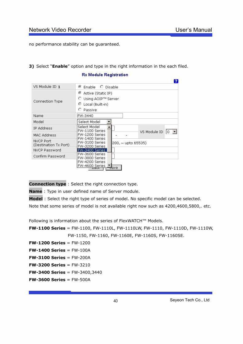
3) Select “Enable” option and type in the right information in the each filed.
Connection type : Select the right connection type.
Name : Type in user defined name of Server module.
Model : Select the right type of series of model. No specific model can be selected.
Note that some series of model is not available right now such as 4200,4600,5800,. etc.
Following is information about the series of FlexWATCH™ Models.
FW-1100 Series = FW-1100, FW-1110L, FW-1110LW, FW-1110, FW-1110D, FW-1110W,
FW-1150, FW-1160, FW-1160E, FW-1160S, FW-1160SE.
FW-1200 Series = FW-1200
FW-1400 Series = FW-100A
FW-3100 Series = FW-200A
FW-3200 Series = FW-3210
FW-3400 Series = FW-3400,3440
FW-3600 Series = FW-500A
Network Video Recorder User’s Manual
Seyeon Tech Co., Ltd
41
FW-5400 Series = FW-5440
VS Module ID: Select “0” for any selected Video Server module, number 1 ~ 15 is for
video expansion in each video server in the future expansion.
NVCP Port : Type in NVCP port number configured in the network camera or video
server.
NVCP Password : It is security feature reside in the FlexWATCHTM server which
authenticate server access by RX module (FW-5440 or 5000 NDVR server) to
FlexWATCHTM server. Once NVCP Password is configured, that password must be set up
in the NDVR server to get video from FlexWATCHTM server. Otherwise, no video
connection can be established between NDVR and FlexWATCHTM server .
4) Once configuration is done, click “Apply” button.
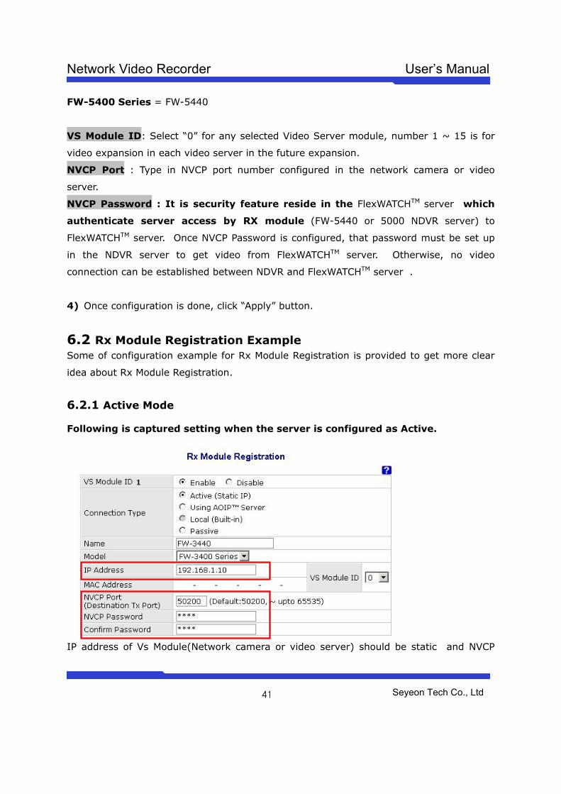
6.2 Rx Module Registration Example Some of configuration example for Rx Module Registration is provided to get more clear
idea about Rx Module Registration.
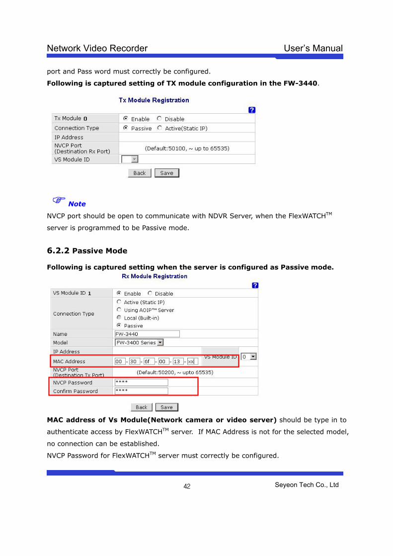
6.2.1 Active Mode Following is captured setting when the server is configured as Active.
IP address of Vs Module(Network camera or video server) should be static and NVCP
Network Video Recorder User’s Manual
Seyeon Tech Co., Ltd
42
port and Pass word must correctly be configured.
Following is captured setting of TX module configuration in the FW-3440.
Note
NVCP port should be open to communicate with NDVR Server, when the FlexWATCHTM
server is programmed to be Passive mode.
6.2.2 Passive Mode Following is captured setting when the server is configured as Passive mode.
MAC address of Vs Module(Network camera or video server) should be type in to
authenticate access by FlexWATCHTM server. If MAC Address is not for the selected model,
no connection can be established.
NVCP Password for FlexWATCHTM server must correctly be configured.
Network Video Recorder User’s Manual
Seyeon Tech Co., Ltd
43
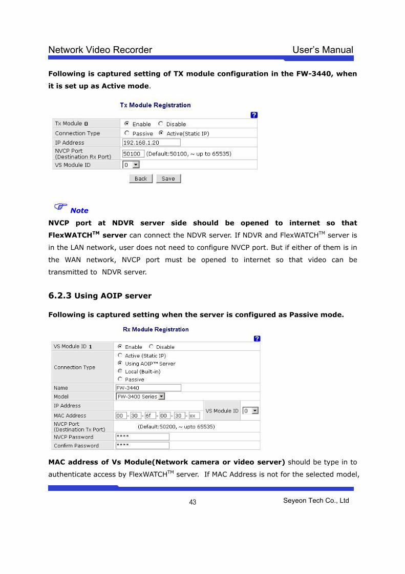
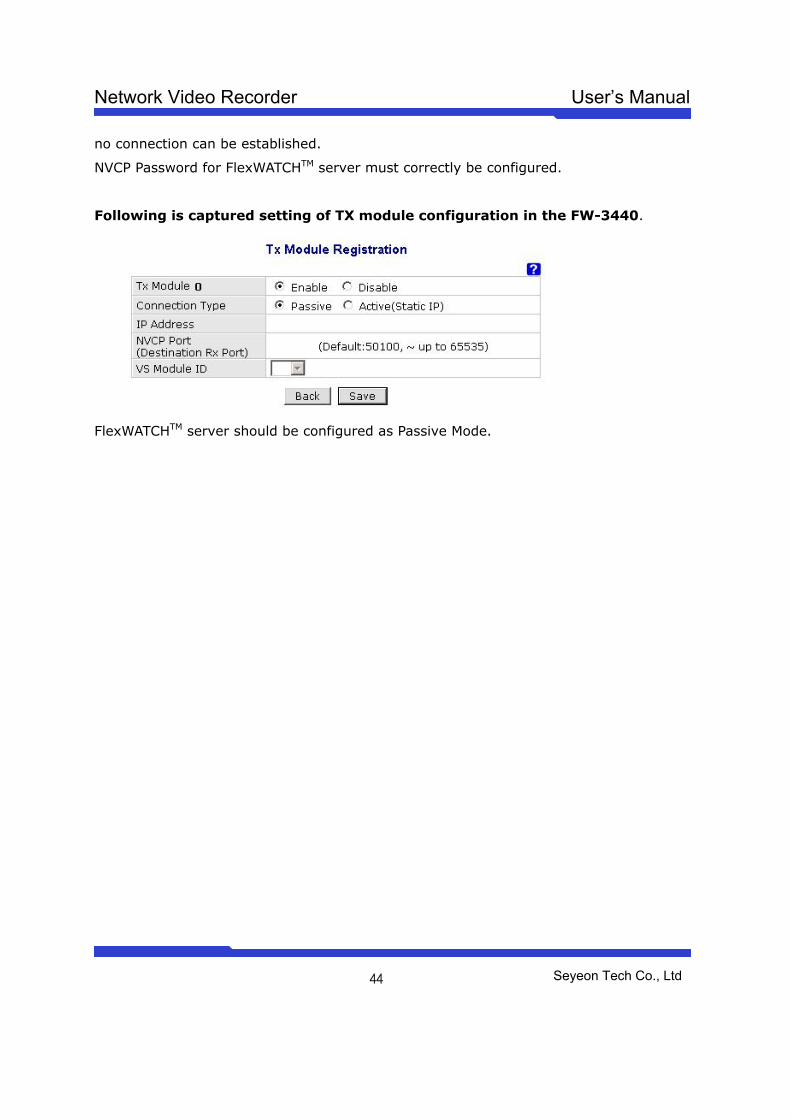
Following is captured setting of TX module configuration in the FW-3440, when
it is set up as Active mode.
Note
NVCP port at NDVR server side should be opened to internet so that
FlexWATCHTM server can connect the NDVR server. If NDVR and FlexWATCHTM server is
in the LAN network, user does not need to configure NVCP port. But if either of them is in
the WAN network, NVCP port must be opened to internet so that video can be
transmitted to NDVR server.
6.2.3 Using AOIP server Following is captured setting when the server is configured as Passive mode.
MAC address of Vs Module(Network camera or video server) should be type in to
authenticate access by FlexWATCHTM server. If MAC Address is not for the selected model,
Network Video Recorder User’s Manual
Seyeon Tech Co., Ltd
44
no connection can be established.
NVCP Password for FlexWATCHTM server must correctly be configured.
Following is captured setting of TX module configuration in the FW-3440.
FlexWATCHTM server should be configured as Passive Mode.
Network Video Recorder User’s Manual
Seyeon Tech Co., Ltd
45
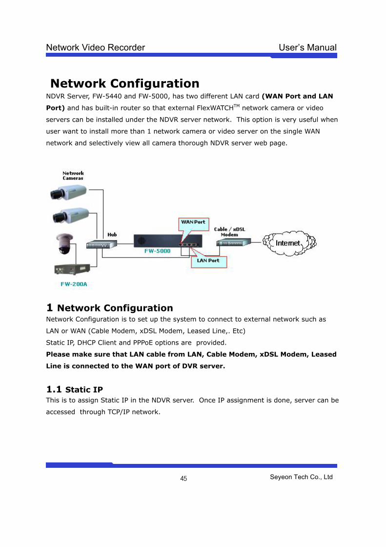
Network Configuration NDVR Server, FW-5440 and FW-5000, has two different LAN card (WAN Port and LAN
Port) and has built-in router so that external FlexWATCHTM network camera or video
servers can be installed under the NDVR server network. This option is very useful when
user want to install more than 1 network camera or video server on the single WAN
network and selectively view all camera thorough NDVR server web page.
1 Network Configuration Network Configuration is to set up the system to connect to external network such as
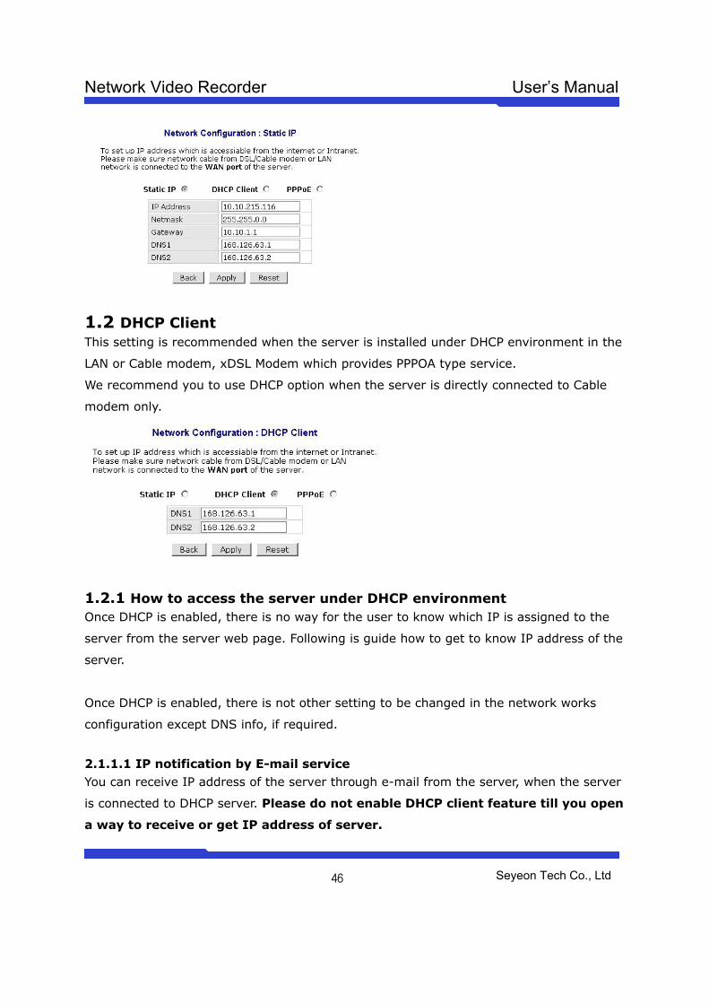
LAN or WAN (Cable Modem, xDSL Modem, Leased Line,. Etc)
Static IP, DHCP Client and PPPoE options are provided.
Please make sure that LAN cable from LAN, Cable Modem, xDSL Modem, Leased
Line is connected to the WAN port of DVR server.
1.1 Static IP This is to assign Static IP in the NDVR server. Once IP assignment is done, server can be
accessed through TCP/IP network.
Network Video Recorder User’s Manual
Seyeon Tech Co., Ltd
46
1.2 DHCP Client This setting is recommended when the server is installed under DHCP environment in the
LAN or Cable modem, xDSL Modem which provides PPPOA type service.
We recommend you to use DHCP option when the server is directly connected to Cable
modem only.
1.2.1 How to access the server under DHCP environment Once DHCP is enabled, there is no way for the user to know which IP is assigned to the
server from the server web page. Following is guide how to get to know IP address of the
server.
Once DHCP is enabled, there is not other setting to be changed in the network works
configuration except DNS info, if required.
2.1.1.1 IP notification by E-mail service You can receive IP address of the server through e-mail from the server, when the server
is connected to DHCP server. Please do not enable DHCP client feature till you open
a way to receive or get IP address of server.
Network Video Recorder User’s Manual
Seyeon Tech Co., Ltd
47
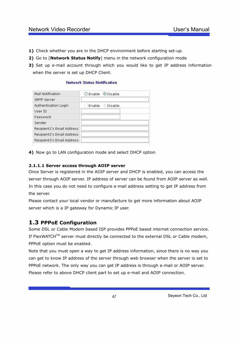
1) Check whether you are in the DHCP environment before starting set-up.
2) Go to [Network Status Notify] menu in the network configuration mode
3) Set up e-mail account through which you would like to get IP address information
when the server is set up DHCP Client.
4) Now go to LAN configuration mode and select DHCP option
2.1.1.1 Server access through AOIP server Once Server is registered in the AOIP server and DHCP is enabled, you can access the
server through AOIP server. IP address of server can be found from AOIP server as well.
In this case you do not need to configure e-mail address setting to get IP address from
the server.
Please contact your local vendor or manufacture to get more information about AOIP
server which is a IP gateway for Dynamic IP user.
1.3 PPPoE Configuration Some DSL or Cable Modem based ISP provides PPPoE based internet connection service.
If FlexWATCHTM server must directly be connected to the external DSL or Cable modem,
PPPoE option must be enabled.
Note that you must open a way to get IP address information, since there is no way you
can get to know IP address of the server through web browser when the server is set to
PPPoE network. The only way you can get IP address is through e-mail or AOIP server.
Please refer to above DHCP client part to set up e-mail and AOIP connection.
Network Video Recorder User’s Manual
Seyeon Tech Co., Ltd
48
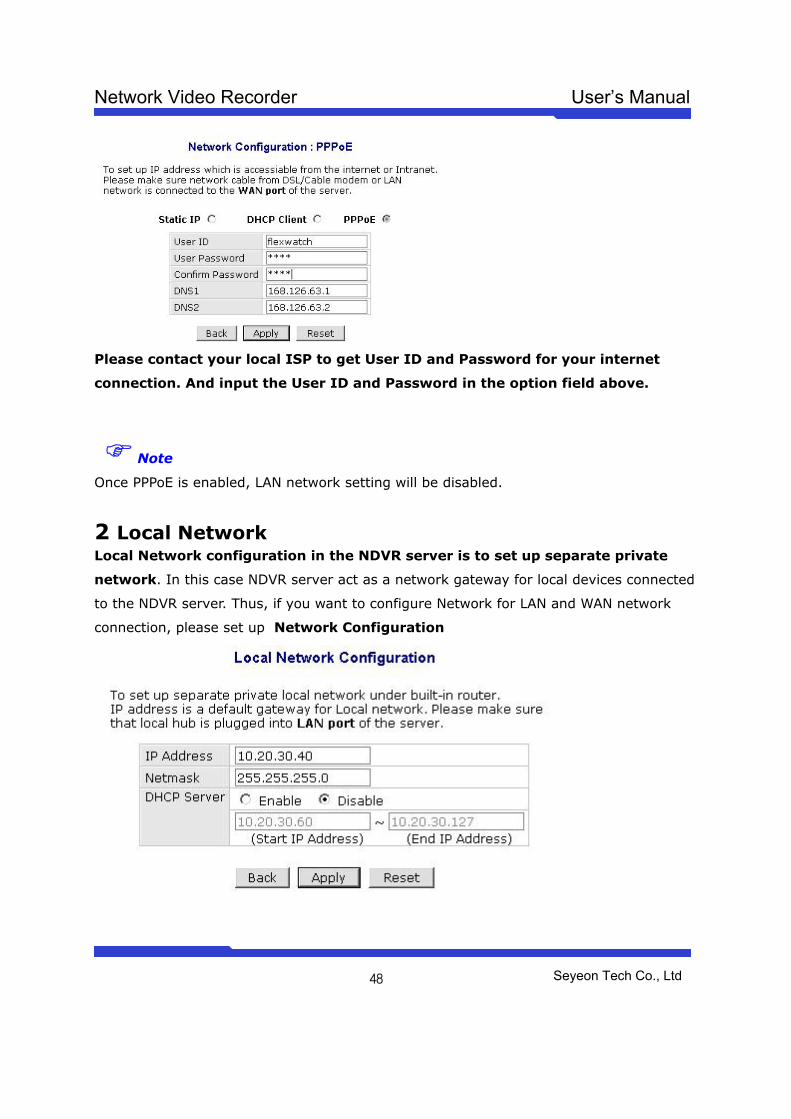
Please contact your local ISP to get User ID and Password for your internet
connection. And input the User ID and Password in the option field above.
Note
Once PPPoE is enabled, LAN network setting will be disabled.
2 Local Network Local Network configuration in the NDVR server is to set up separate private
network. In this case NDVR server act as a network gateway for local devices connected
to the NDVR server. Thus, if you want to configure Network for LAN and WAN network
connection, please set up Network Configuration

Network Video Recorder User’s Manual
Seyeon Tech Co., Ltd
49
IP Address : IP address of this NDVR server which is default gateway for local device.
Netmask : Multiple class of private network can be set up through this Netmask (A
class:255.0.0.0, B class:255.255.0.0, C class : 255,255,255,0)
DHCP Server : NDVR sever act as a DHCP server when it is enabled and IP for local
device will automatically assigned. It is highly recommended to disable DHCP option and
give static IP address for the local device.
Please make sure that LAN cable for separate private network is connected to
LAN port of the NDVR server
3 Port Mapping Through Port mapping function, FlexWATCHTM network camera or video server connected
to the LAN (separate private network connected to LAN port of the NDVR server) under
NDVR server can be accessed from WAN network ( Connected to WAN port of the NDVR
server).
Service Protocol :
Select the right protocol type for communication protocol, Most of protocols used for
FlexWATCHTM network camera or video server such as HTTP, NVCP, NIPP, FTP
and Telnet port is TCP protocol. UDP protocol is used when the Voice kit (FW-
V10s) is connected the FlexWATCHTM network camera or video server.
External port :
It is a virtual port through which local device (LAN network) can communicate with the
device from the WAN network. Assignable rage of Port number is 1~65535. User can
Network Video Recorder User’s Manual
Seyeon Tech Co., Ltd
50
assign any port number with the range. But be sure that the port number is not
duplicated by other device as well.
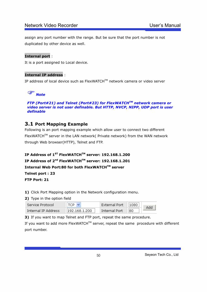
Internal port :
It is a port assigned to Local device.
Internal IP address :
IP address of local device such as FlexWATCHTM network camera or video server
Note
FTP (Port#21) and Telnet (Port#23) for FlexWATCHTM network camera or video server is not user definable. But HTTP, NVCP, NIPP, UDP port is user definable
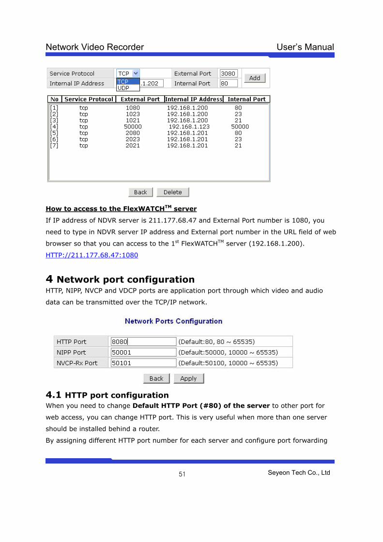
3.1 Port Mapping Example Following is an port mapping example which allow user to connect two different
FlexWATCHTM server in the LAN network( Private network) from the WAN network
through Web browser(HTTP), Telnet and FTP.
IP Address of 1ST FlexWATCHTM server: 192.168.1.200
IP Address of 2nd FlexWATCHTM server: 192.168.1.201
Internal Web Port:80 for both FlexWATCHTM server
Telnet port : 23
FTP Port: 21
1) Click Port Mapping option in the Network configuration menu.
2) Type in the option field
3) If you want to map Telnet and FTP port, repeat the same procedure.
If you want to add more FlexWATCHTM server, repeat the same procedure with different
port number.
Network Video Recorder User’s Manual
Seyeon Tech Co., Ltd
51
How to access to the FlexWATCHTM server
If IP address of NDVR server is 211.177.68.47 and External Port number is 1080, you
need to type in NDVR server IP address and External port number in the URL field of web
browser so that you can access to the 1st FlexWATCHTM server (192.168.1.200).
HTTP://211.177.68.47:1080
4 Network port configuration HTTP, NIPP, NVCP and VDCP ports are application port through which video and audio
data can be transmitted over the TCP/IP network.
4.1 HTTP port configuration When you need to change Default HTTP Port (#80) of the server to other port for
web access, you can change HTTP port. This is very useful when more than one server
should be installed behind a router.
By assigning different HTTP port number for each server and configure port forwarding
Network Video Recorder User’s Manual
Seyeon Tech Co., Ltd
52
feature of Router, you can install more than one server behind the router.
For more information about this, please contact your local vendor.
4.2 NIPP Port This is port through which archived video can be playback through internet net. If NIPP
Port is not open to internet no recorded video can be playback.
This port number is user definable.
4.3 NVCP –Rx Port Rx port is a TCP port number through which NDVR server can communicate with
FlexWATCHTM server so that video can be transmitted into NDVR server. This port
number is user definable.
NVCP-Rx port must be opened when the NDVR server is to get video from FlexWATCHTM
server through internet in a Passive way (When RX Module Registration is
configured as PASSIVE MODE). When NVCP port is to be used, you must open TCP
port in the router as well.
5 WAN Configuration and Application Server is designed to make a call to ISP or can receive a call from outside so that server
can establish internet connect to send FTP, e-mail or send video & data through PSTN line
or other medium. This is best alternative when the broadband internet access is not
available.
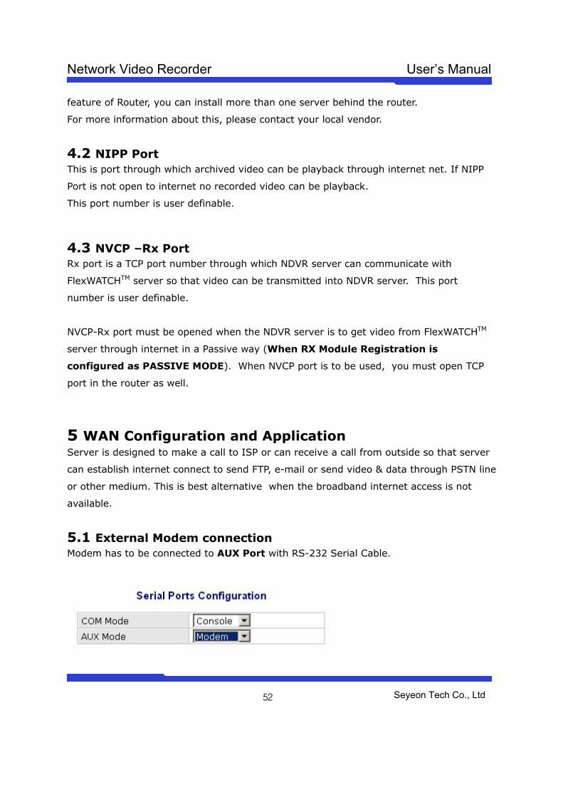
5.1 External Modem connection Modem has to be connected to AUX Port with RS-232 Serial Cable.
Network Video Recorder User’s Manual
Seyeon Tech Co., Ltd
53
1) Connect your MODEM and AUX Port at FlexWATCHTM server with RS-232 Serial cable.
2) Go to Admin Menu >> System Configuration >> Serial Ports Configuration
3) Select ‘Modem’ at AUX mode and click ‘Apply’ button.
4) System reboot will be recommended, then click ‘Reboot’ button.
5.2 Application with Dial-in/out feature 5.2.1 Application with Dial-in Dial-in is to allow server connection from remote client. This option is useful for the user
to connect the server at any time. Especially when the server send e-mail notification for
the alarm and user want to check the situation.
5.2.2 Application with Dial-out Server can establish the internet connection through PSTN line and send FTP or e-mail
when the alarm condition is triggered by any event.
Following can be done through Dial-out function
• Pre/post alarm image sending through e-mail
• Pre/post alarm image sending to FTP server through FTP function
• Establish connection with AOIP server :
when the event is happened, server can send e-mail notification for the alarm and can
keep the connection with AOIP server, not terminating the connection with ISP.
Thus, you can quickly connect the server through AOIP server and view live video. The
key benefit of using AOIP connection is to view live video without making a separate call
to FlexWATCHTM server whenever there is alarm and you can easily access the server. If
you are running FW-Manager software, live video will be automatically display on the FW-
manager screen when there is any alarm.
5.3 Dial Out configuration This is to set up the system to make a call to ISP when the dial out condition is activated
to transmit live video or send e-mail or FTP image.
5.3.1 Dial-up through Standard modem
Network Video Recorder User’s Manual
Seyeon Tech Co., Ltd
54
Dial-out through standard PSTN modem is quite common and general.
1) Connect the server to PSTN line through RS-232 cable. Connect the cable to COM Port
or server. Use the standard D-Sub 9pin connector provided by PSTN modem.
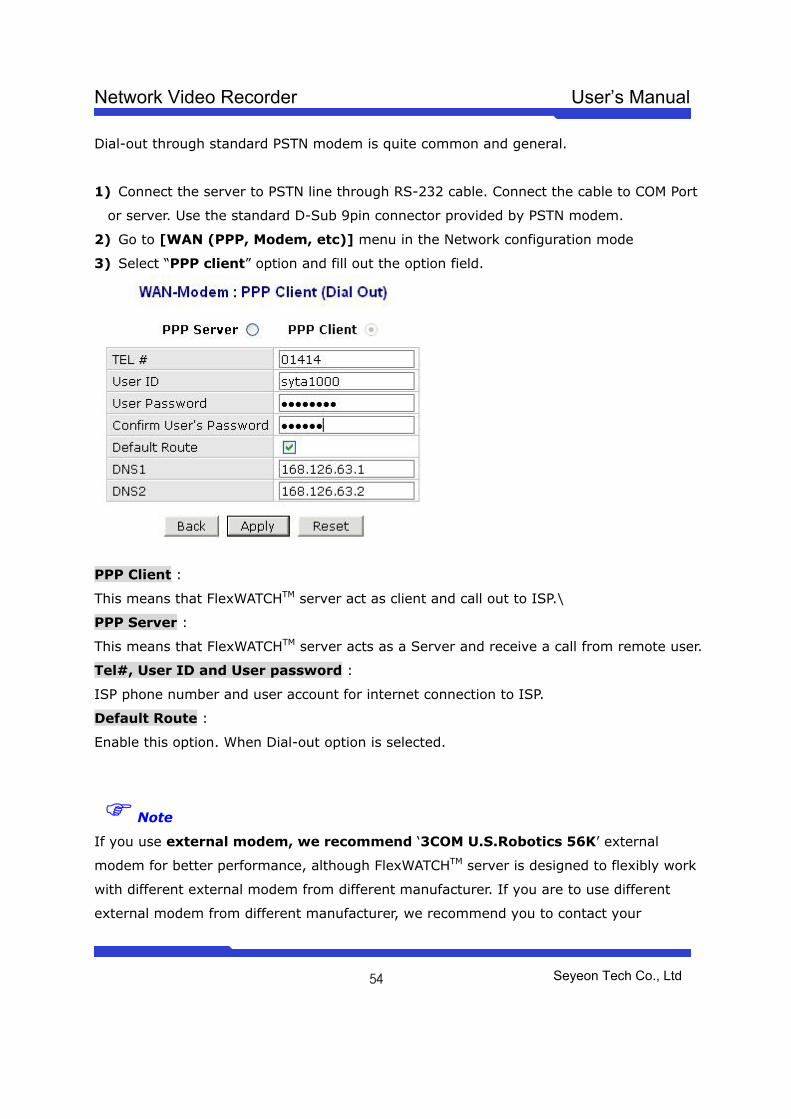
2) Go to [WAN (PPP, Modem, etc)] menu in the Network configuration mode
3) Select “PPP client” option and fill out the option field.
PPP Client :
This means that FlexWATCHTM server act as client and call out to ISP.\
PPP Server :
This means that FlexWATCHTM server acts as a Server and receive a call from remote user.
Tel#, User ID and User password :
ISP phone number and user account for internet connection to ISP.
Default Route :
Enable this option. When Dial-out option is selected.
Note
If you use external modem, we recommend ‘3COM U.S.Robotics 56K’ external
modem for better performance, although FlexWATCHTM server is designed to flexibly work
with different external modem from different manufacturer. If you are to use different
external modem from different manufacturer, we recommend you to contact your
Network Video Recorder User’s Manual
Seyeon Tech Co., Ltd
55
distributor or contact [email protected] to choose compatible modem.
5.3.2 Dial-Out through Media specific device Dial-out can be done through specific media which is not standard PSTN such as CDMA
modem, GSM or GPRS Modem or any type of wireless modem.
This mode is not for general users. Thus, if you need to connect special modem device,
please contact your vendor or manufacturer for more information, [email protected]
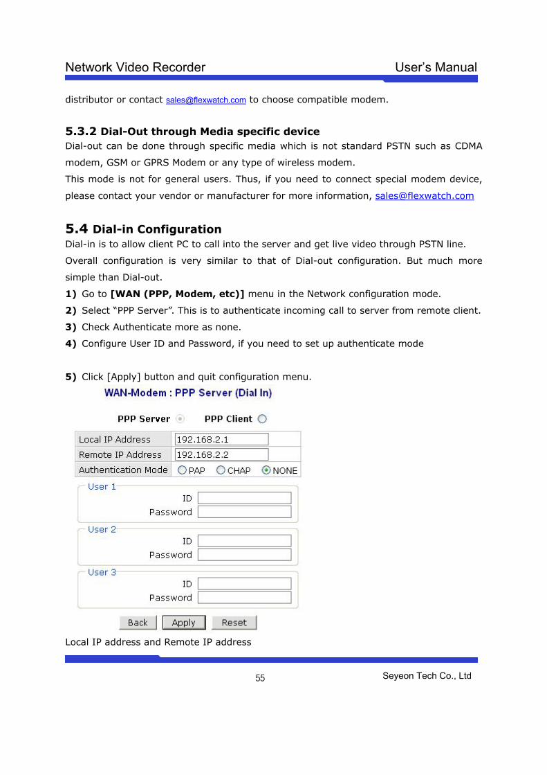
5.4 Dial-in Configuration Dial-in is to allow client PC to call into the server and get live video through PSTN line.
Overall configuration is very similar to that of Dial-out configuration. But much more
simple than Dial-out.
1) Go to [WAN (PPP, Modem, etc)] menu in the Network configuration mode.
2) Select “PPP Server”. This is to authenticate incoming call to server from remote client.
3) Check Authenticate more as none.
4) Configure User ID and Password, if you need to set up authenticate mode
5) Click [Apply] button and quit configuration menu.
Local IP address and Remote IP address
Network Video Recorder User’s Manual
Seyeon Tech Co., Ltd
56
When remote client is connected to the server through modem connection, physical line
connection will be done. But no way to view live video unless client run the web browser
of the FlexWATCHTM server.
Local IP address and Remote IP address is virtual IP address which is used at the time of
Modem connection only
Local IP address :
System default IP address (192.168.2.1) resides in the FlexWATCHTM server for modem
connection only. So when you connect the FlexWATCHTM server from remote PC using
dial-up networking and physical connection is made, you need to run your web browser
and enter this system default IP address(192.168.2.1) to view live video. You can
change this system default IP address as well. But it is recommended not to change
system default IP address for modem connection to prevent any possible error.
Remote IP address :
IP address which is automatically given to remote client PC by FlexWATCHTM server when
FlexWATCHTM server is connected by remote client PC using dial-up networking. This IP
address (192.168.2.2) is for data communication between FlexWATCHTM server and
Remote client PC. So you do not need to change this IP address. But if you change
default IP address of FlexWATCHTM server (192.168.2.1) for modem connection to
different class of IP address, you need to change remote IP address to the same class
of IP to match the IP class.
Note that when Local IP address is change, remote IP address should be changed into the same class of the IP address.
6 Network Status Notify Network Status Notify is to send IP address of FlexWATCHTM server assigned by DHCP
server or ISP to mail recipient.
Network Status Notify option is use when you want to get changed IP address to the
server whenever the different IP address is assigned to FlexWATCHTM server.
Network Status Notify option can be used for following network environment.
• When the server is connected to PSTN Modem connection with Dial-up to
ISP by event
Network Video Recorder User’s Manual
Seyeon Tech Co., Ltd
57
• When the DHCP option is selected
• When the PPPoE option is selected
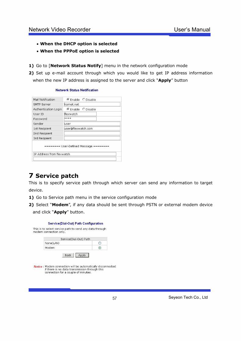
1) Go to [Network Status Notify] menu in the network configuration mode
2) Set up e-mail account through which you would like to get IP address information
when the new IP address is assigned to the server and click “Apply” button
7 Service patch This is to specify service path through which server can send any information to target
device.
1) Go to Service path menu in the service configuration mode
2) Select “Modem”, if any data should be sent through PSTN or external modem device
and click “Apply” button.

Network Video Recorder User’s Manual
Seyeon Tech Co., Ltd
58
LAN : This is default path the send any data to outside.
Modem : when PSTN or other medium than LAN is used to send data to outside. This
service port must be checked when any data is to be sent through PSTN or other medium
than LAN which is connected to COM port.
Note
Service patch must be set up and checked before starting WAN configuration to send any
data through external PSTN modem connection or equivalent
If LAN is to be used, select “None(LAN)” option.
8 AOIP Setup AOIP (Always-On-IP) is a IP gateway through which user can access the FlexWATCHTM
server when it is connected to Dynamic IP address. Thus, if the server should be
connected to the Dynamic IP network and you want to view live video from anywhere, it
is the right solution for you.
8.1 How to use AOIP service Following is a step you need to take to use AOIP service
- Contact your local vendor or [email protected] to get user account for
AOIP service.
- Register product in the AOIP server under your account
- Set up your network (Port mapping function of your router)
- Enable AOIP service option in the FlexWATCHTM server.
- Once things are set up, you can login to AOIP server and connect your
FlexWATCHTM server.
Note
AOIP is proprietary data service run by FlexWATCH or its business partners around the
world. Thus, depending on the country AOIP service can run by your local vendor or
master distributor or in some case, you need to user AOIP server run by manufacturer.
More detailed information about how to use can be acquired by contact your local
distributor or [email protected] .
Network Video Recorder User’s Manual
Seyeon Tech Co., Ltd
59
8.2 AOIP configuration As described above, once you register product in the AOIP server and Network setting is
correctly done to user AOIP function, you need to configure AOIP function in the
FlexWATCHTM server.
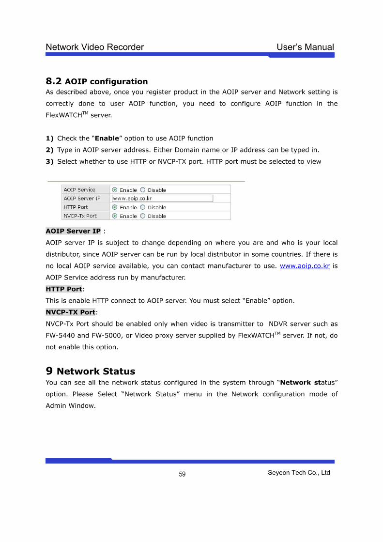
1) Check the “Enable” option to use AOIP function
2) Type in AOIP server address. Either Domain name or IP address can be typed in.
3) Select whether to use HTTP or NVCP-TX port. HTTP port must be selected to view
AOIP Server IP :
AOIP server IP is subject to change depending on where you are and who is your local
distributor, since AOIP server can be run by local distributor in some countries. If there is
no local AOIP service available, you can contact manufacturer to use. www.aoip.co.kr is
AOIP Service address run by manufacturer.
HTTP Port:
This is enable HTTP connect to AOIP server. You must select “Enable” option.
NVCP-TX Port:
NVCP-Tx Port should be enabled only when video is transmitter to NDVR server such as
FW-5440 and FW-5000, or Video proxy server supplied by FlexWATCHTM server. If not, do
not enable this option.
9 Network Status You can see all the network status configured in the system through “Network status”
option. Please Select “Network Status” menu in the Network configuration mode of
Admin Window.
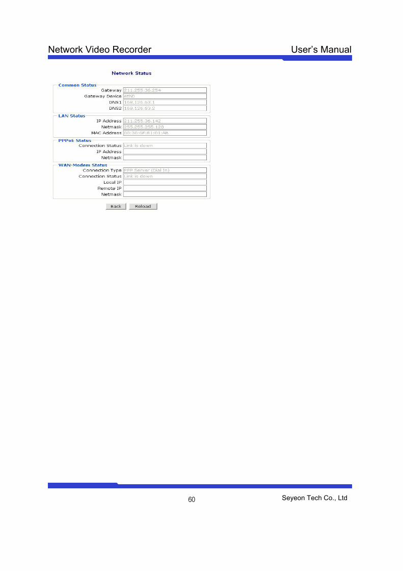
Network Video Recorder User’s Manual
Seyeon Tech Co., Ltd
60
Network Video Recorder User’s Manual
Seyeon Tech Co., Ltd
61
Recording & Playback
1 General Setting for Recording 1.1 Hard Disk Configuration 1.1.1 Before Installing HDD Make sure that system is properly shut down before you install or detach HDD from the
server, since there is high possibility that File system may be affected by improper
handling of HDD.
Make sure that Jumper of HDD is on Master position before you install HDD. Otherwise,
HDD will not be recognized by the server. You need to refer to User’s Guide of HDD for
jumper Setting.
When you use already formatted HDD (Linux file system or FAT32), only the first
partition of HDD will be used for recording. However, it is highly recommended to format
HDD before you start recording.
1.1.2 File System Type NSS-1016 support either Linux native file system(ext3) and Window FAT 32 and you can
select any type you would like to use. After power on, NSS detect the type of HDD file
system and use it.
File System Type Description
Linux file system (default)
Minimize any possible file crash in case of sudden power down or inappropriate system down. But user can not read data directly when the recorded HDD cartridge is inserted into desk- top PC with Window OS, since it is Linux file system.
Window file system (FAT32)
Windows file system can be read from any Windows O/S, when removal HDD Cartridge is collected from different place and inserted into other Window PC. But high possibility file system can be affected and crashed by sudden power shut down. Thus, not recommended if there is power supply is not stable.
1.1.3 Installation of HDD NVR server hardware comes with HDD Rack only. Thus, user needs to procure supported
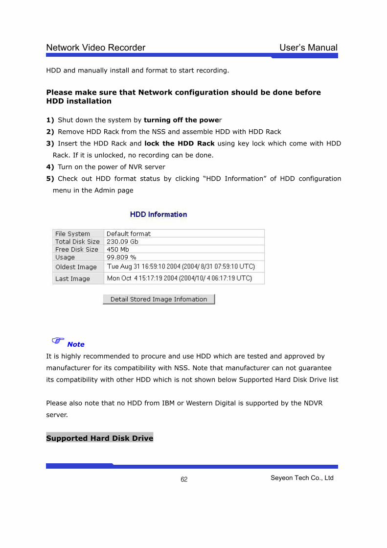
Network Video Recorder User’s Manual
Seyeon Tech Co., Ltd
62
HDD and manually install and format to start recording.
Please make sure that Network configuration should be done before HDD installation 1) Shut down the system by turning off the power
2) Remove HDD Rack from the NSS and assemble HDD with HDD Rack
3) Insert the HDD Rack and lock the HDD Rack using key lock which come with HDD
Rack. If it is unlocked, no recording can be done.
4) Turn on the power of NVR server
5) Check out HDD format status by clicking “HDD Information” of HDD configuration
menu in the Admin page
Note
It is highly recommended to procure and use HDD which are tested and approved by
manufacturer for its compatibility with NSS. Note that manufacturer can not guarantee
its compatibility with other HDD which is not shown below Supported Hard Disk Drive list
Please also note that no HDD from IBM or Western Digital is supported by the NDVR
server.
Supported Hard Disk Drive
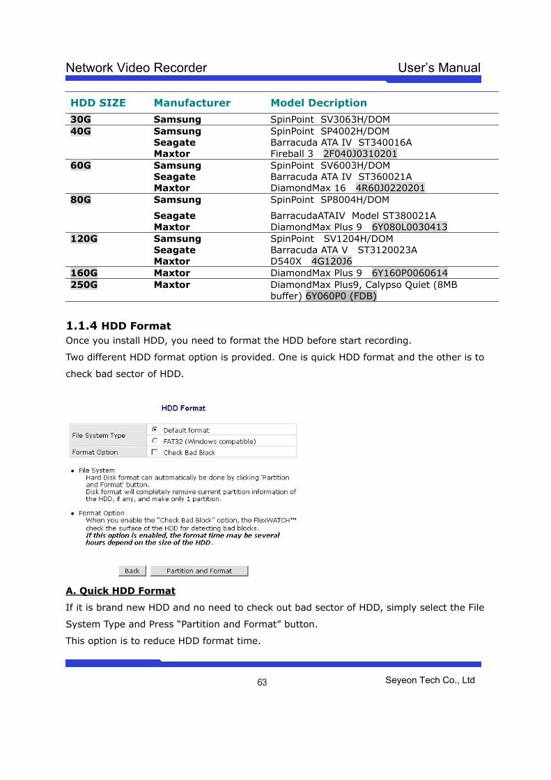
Network Video Recorder User’s Manual
Seyeon Tech Co., Ltd
63
HDD SIZE Manufacturer Model Decription
30G Samsung SpinPoint SV3063H/DOM Samsung SpinPoint SP4002H/DOM Seagate Barracuda ATA IV ST340016A
40G
Maxtor Fireball 3 2F040J0310201 Samsung SpinPoint SV6003H/DOM Seagate Barracuda ATA IV ST360021A
60G
Maxtor DiamondMax 16 4R60J0220201 Samsung SpinPoint SP8004H/DOM
Seagate BarracudaATAIV Model ST380021A
80G
Maxtor DiamondMax Plus 9 6Y080L0030413 Samsung SpinPoint SV1204H/DOM Seagate Barracuda ATA V ST3120023A
120G
Maxtor D540X 4G120J6 160G Maxtor DiamondMax Plus 9 6Y160P0060614 250G Maxtor DiamondMax Plus9, Calypso Quiet (8MB
buffer) 6Y060P0 (FDB)
1.1.4 HDD Format Once you install HDD, you need to format the HDD before start recording.
Two different HDD format option is provided. One is quick HDD format and the other is to
check bad sector of HDD.
A. Quick HDD Format
If it is brand new HDD and no need to check out bad sector of HDD, simply select the File
System Type and Press “Partition and Format” button.
This option is to reduce HDD format time.
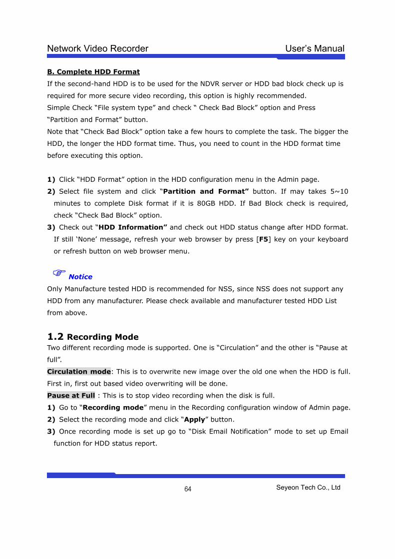
Network Video Recorder User’s Manual
Seyeon Tech Co., Ltd
64
B. Complete HDD Format
If the second-hand HDD is to be used for the NDVR server or HDD bad block check up is
required for more secure video recording, this option is highly recommended.
Simple Check “File system type” and check “ Check Bad Block” option and Press
“Partition and Format” button.
Note that “Check Bad Block” option take a few hours to complete the task. The bigger the
HDD, the longer the HDD format time. Thus, you need to count in the HDD format time
before executing this option.
1) Click “HDD Format” option in the HDD configuration menu in the Admin page.
2) Select file system and click “Partition and Format” button. If may takes 5~10
minutes to complete Disk format if it is 80GB HDD. If Bad Block check is required,
check “Check Bad Block” option.
3) Check out “HDD Information” and check out HDD status change after HDD format.
If still ‘None’ message, refresh your web browser by press [F5] key on your keyboard
or refresh button on web browser menu.
Notice
Only Manufacture tested HDD is recommended for NSS, since NSS does not support any
HDD from any manufacturer. Please check available and manufacturer tested HDD List
from above.
1.2 Recording Mode Two different recording mode is supported. One is “Circulation” and the other is “Pause at
full”.
Circulation mode: This is to overwrite new image over the old one when the HDD is full.
First in, first out based video overwriting will be done.
Pause at Full : This is to stop video recording when the disk is full.
1) Go to “Recording mode” menu in the Recording configuration window of Admin page.
2) Select the recording mode and click “Apply” button.
3) Once recording mode is set up go to “Disk Email Notification” mode to set up Email
function for HDD status report.
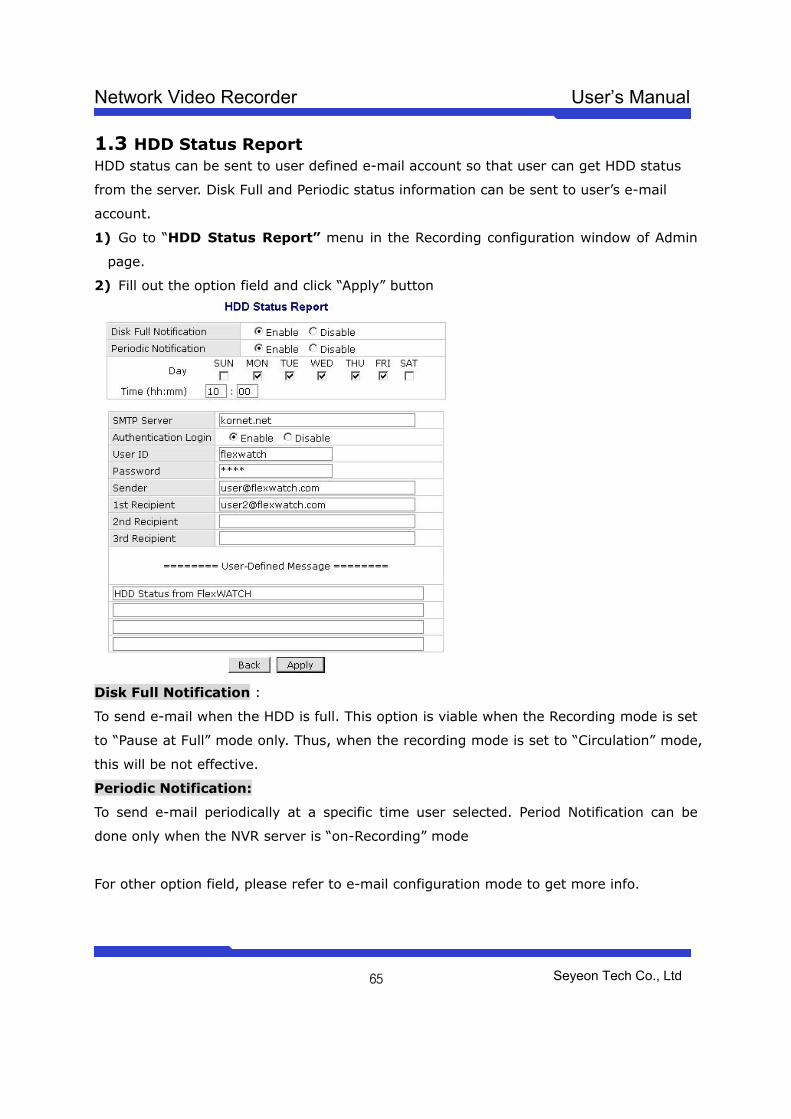
Network Video Recorder User’s Manual
Seyeon Tech Co., Ltd
65
1.3 HDD Status Report HDD status can be sent to user defined e-mail account so that user can get HDD status
from the server. Disk Full and Periodic status information can be sent to user’s e-mail
account.
1) Go to “HDD Status Report” menu in the Recording configuration window of Admin
page.
2) Fill out the option field and click “Apply” button
Disk Full Notification :
To send e-mail when the HDD is full. This option is viable when the Recording mode is set
to “Pause at Full” mode only. Thus, when the recording mode is set to “Circulation” mode,
this will be not effective.
Periodic Notification:
To send e-mail periodically at a specific time user selected. Period Notification can be
done only when the NVR server is “on-Recording” mode
For other option field, please refer to e-mail configuration mode to get more info.
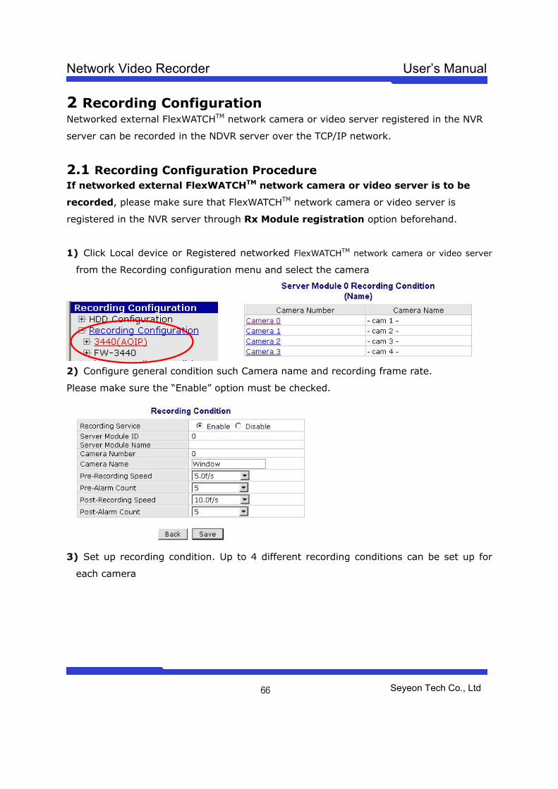
Network Video Recorder User’s Manual
Seyeon Tech Co., Ltd
66
2 Recording Configuration Networked external FlexWATCHTM network camera or video server registered in the NVR
server can be recorded in the NDVR server over the TCP/IP network.
2.1 Recording Configuration Procedure If networked external FlexWATCHTM network camera or video server is to be
recorded, please make sure that FlexWATCHTM network camera or video server is
registered in the NVR server through Rx Module registration option beforehand.
1) Click Local device or Registered networked FlexWATCHTM network camera or video server
from the Recording configuration menu and select the camera
2) Configure general condition such Camera name and recording frame rate.
Please make sure the “Enable” option must be checked.
3) Set up recording condition. Up to 4 different recording conditions can be set up for
each camera
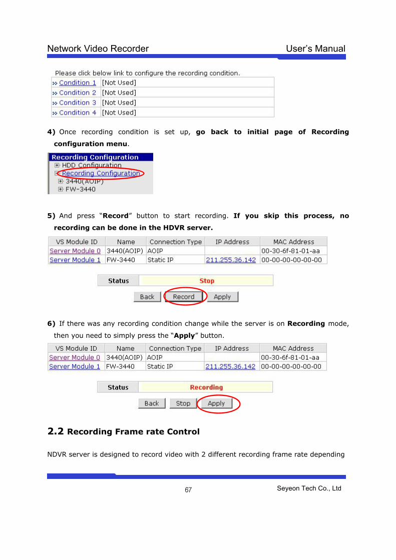
Network Video Recorder User’s Manual
Seyeon Tech Co., Ltd
67
4) Once recording condition is set up, go back to initial page of Recording
configuration menu.
5) And press “Record” button to start recording. If you skip this process, no
recording can be done in the HDVR server.
6) If there was any recording condition change while the server is on Recording mode,
then you need to simply press the “Apply” button.
2.2 Recording Frame rate Control
NDVR server is designed to record video with 2 different recording frame rate depending
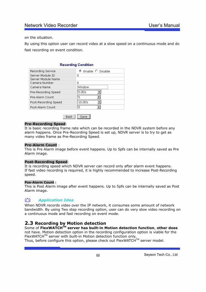
Network Video Recorder User’s Manual
Seyeon Tech Co., Ltd
68
on the situation.
By using this option user can record video at a slow speed on a continuous mode and do
fast recording on event condition.
Pre-Recording Speed: It is basic recording frame rate which can be recorded in the NDVR system before any alarm happens. Once Pre-Recording Speed is set up, NDVR server is to try to get as many video frame as Pre-Recording Speed. Pre-Alarm Count : This is Pre Alarm image before event happens. Up to 5pfs can be internally saved as Pre Alarm image. Post-Recording Speed: It is recording speed which NDVR server can record only after alarm event happens. If fast video recording is required, it is highly recommended to increase Post-Recording speed. Pos-Alarm Count : This is Post Alarm image after event happens. Up to 5pfs can be internally saved as Post Alarm image.
Application Idea When NDVR records video over the IP network, it consumes some amount of network bandwidth. By using Two step recording option, user can do very slow video recording on a continuous mode and fast recording on event mode.
2.3 Recording by Motion detection Some of FlexWATCHTM server has built-in Motion detection function, other does not have. Motion detection option in the recording configuration option is viable for the FlexWATCHTM server with built-in Motion detection function only. Thus, before configure this option, please check out FlexWATCHTM server model.
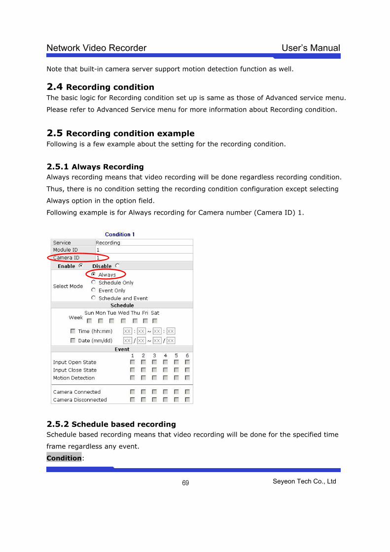
Network Video Recorder User’s Manual
Seyeon Tech Co., Ltd
69
Note that built-in camera server support motion detection function as well.
2.4 Recording condition The basic logic for Recording condition set up is same as those of Advanced service menu.
Please refer to Advanced Service menu for more information about Recording condition.
2.5 Recording condition example Following is a few example about the setting for the recording condition.
2.5.1 Always Recording Always recording means that video recording will be done regardless recording condition.
Thus, there is no condition setting the recording condition configuration except selecting
Always option in the option field.
Following example is for Always recording for Camera number (Camera ID) 1.
2.5.2 Schedule based recording Schedule based recording means that video recording will be done for the specified time
frame regardless any event.
Condition:
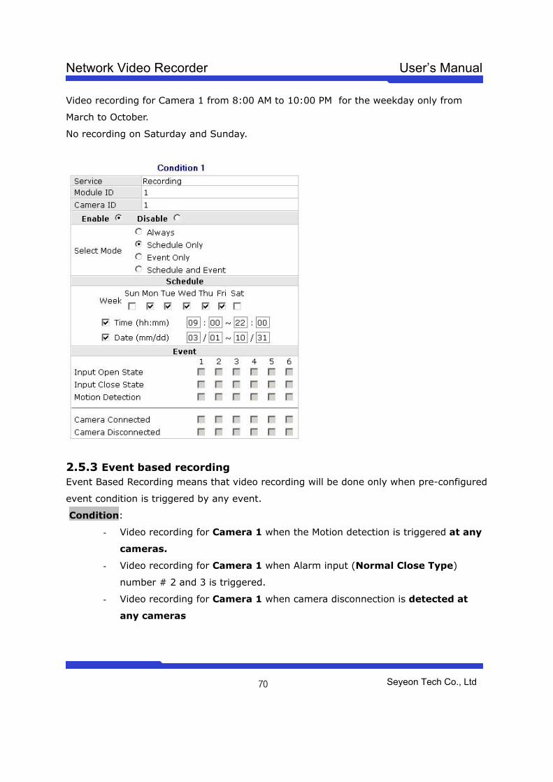
Network Video Recorder User’s Manual
Seyeon Tech Co., Ltd
70
Video recording for Camera 1 from 8:00 AM to 10:00 PM for the weekday only from
March to October.
No recording on Saturday and Sunday.
2.5.3 Event based recording Event Based Recording means that video recording will be done only when pre-configured
event condition is triggered by any event.
Condition:
- Video recording for Camera 1 when the Motion detection is triggered at any
cameras.
- Video recording for Camera 1 when Alarm input (Normal Close Type)
number # 2 and 3 is triggered.
- Video recording for Camera 1 when camera disconnection is detected at
any cameras
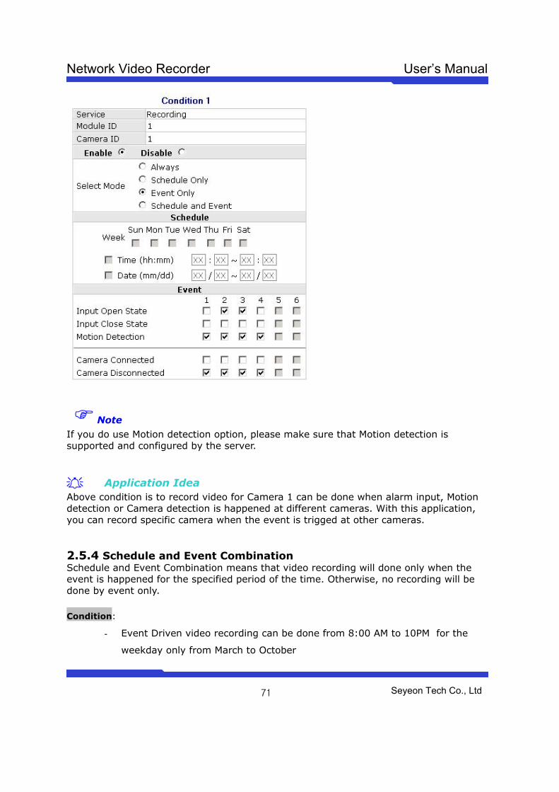
Network Video Recorder User’s Manual
Seyeon Tech Co., Ltd
71
Note If you do use Motion detection option, please make sure that Motion detection is supported and configured by the server.
Application Idea Above condition is to record video for Camera 1 can be done when alarm input, Motion detection or Camera detection is happened at different cameras. With this application, you can record specific camera when the event is trigged at other cameras. 2.5.4 Schedule and Event Combination Schedule and Event Combination means that video recording will done only when the event is happened for the specified period of the time. Otherwise, no recording will be done by event only. Condition:
- Event Driven video recording can be done from 8:00 AM to 10PM for the
weekday only from March to October
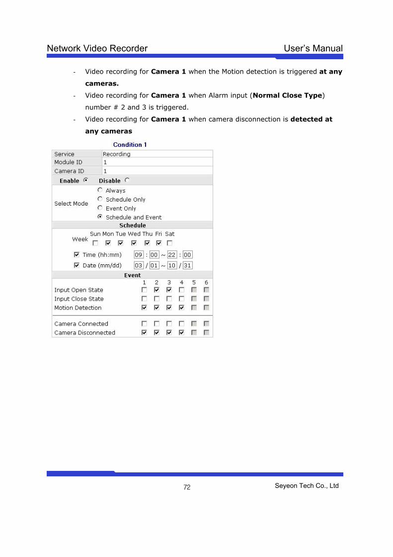
Network Video Recorder User’s Manual
Seyeon Tech Co., Ltd
72
- Video recording for Camera 1 when the Motion detection is triggered at any
cameras.
- Video recording for Camera 1 when Alarm input (Normal Close Type)
number # 2 and 3 is triggered.
- Video recording for Camera 1 when camera disconnection is detected at
any cameras
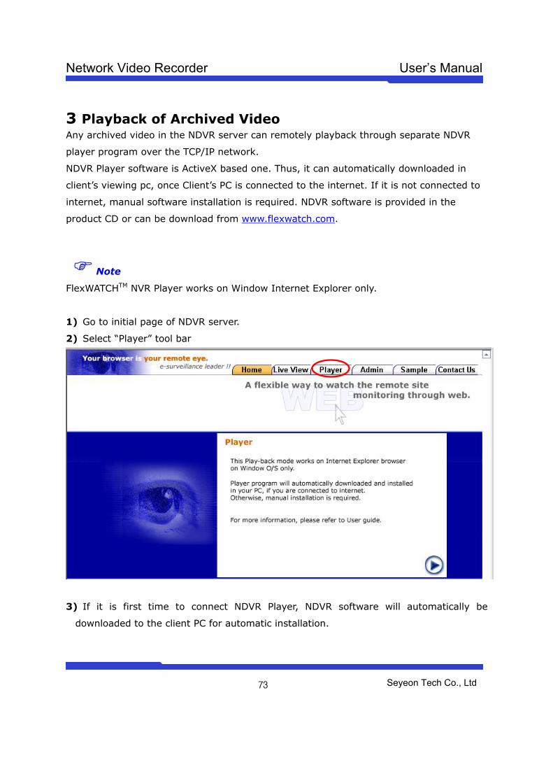
Network Video Recorder User’s Manual
Seyeon Tech Co., Ltd
73
3 Playback of Archived Video Any archived video in the NDVR server can remotely playback through separate NDVR
player program over the TCP/IP network.
NDVR Player software is ActiveX based one. Thus, it can automatically downloaded in
client’s viewing pc, once Client’s PC is connected to the internet. If it is not connected to
internet, manual software installation is required. NDVR software is provided in the
product CD or can be download from www.flexwatch.com.
Note
FlexWATCHTM NVR Player works on Window Internet Explorer only.
1) Go to initial page of NDVR server.
2) Select “Player” tool bar
3) If it is first time to connect NDVR Player, NDVR software will automatically be
downloaded to the client PC for automatic installation.
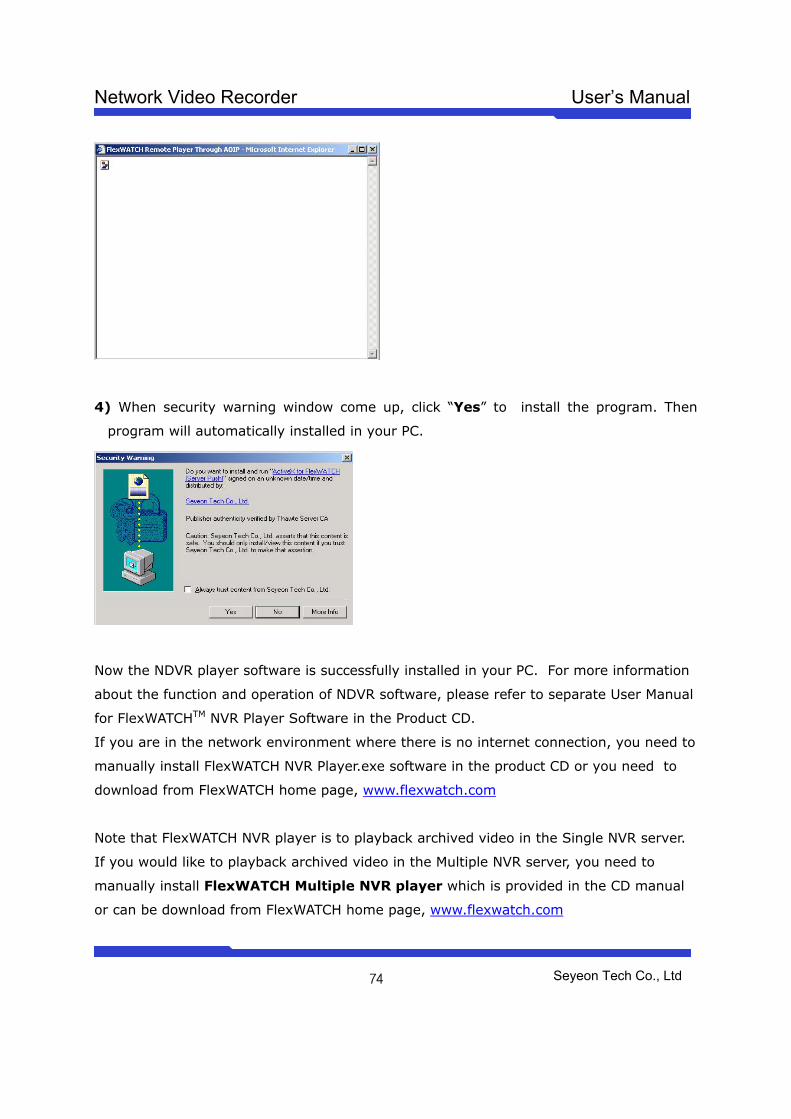
Network Video Recorder User’s Manual
Seyeon Tech Co., Ltd
74
4) When security warning window come up, click “Yes” to install the program. Then
program will automatically installed in your PC.
Now the NDVR player software is successfully installed in your PC. For more information
about the function and operation of NDVR software, please refer to separate User Manual
for FlexWATCHTM NVR Player Software in the Product CD.
If you are in the network environment where there is no internet connection, you need to
manually install FlexWATCH NVR Player.exe software in the product CD or you need to
download from FlexWATCH home page, www.flexwatch.com
Note that FlexWATCH NVR player is to playback archived video in the Single NVR server.
If you would like to playback archived video in the Multiple NVR server, you need to
manually install FlexWATCH Multiple NVR player which is provided in the CD manual
or can be download from FlexWATCH home page, www.flexwatch.com
Network Video Recorder User’s Manual
Seyeon Tech Co., Ltd
75
Utilities Utilities is to manage and control system properly. Save Configuration, Flash Update,
System Reboot and system upgrade options are provided.
1 Save Configuration This is to temporally save all new configuration and settings in the system memory. Once
new configuration is saved by “Save Configuration” menu, new configuration will
permanently saved in the system memory only after system Reboot.
2 Reboot Reboot is to permanently save all new configuration or settings in the system memory.
Thus, it is highly recommended to reboot the system after executing “Save
Configuration” menu.
Most of case system reboot come last only after all the new configuration is done. But
some of system menu require system reboot in the middle of system configuration so
that new setting can properly applied in the system.
Followings are list of option which require System reboot.
- Network Configuration
- Serial Port configuration
- Memory assignment for Advance Service
- Factory Default
Note
System reboot requires about 1Minutes of lead time. Thus, if you execute Reboot option,
please wait at least 1minutes to do other settings.
3 Factory Default Factory Default is to reset the system to start all the configuration from the factory
default status. This utility is recommended to use only when you lost all of your logics for
system configuration, since all of you setting will be lost by executing this option Except
Network configuration.
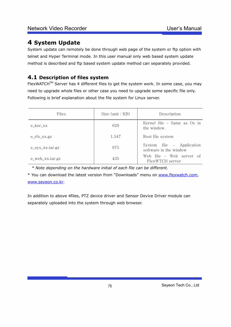
Network Video Recorder User’s Manual
Seyeon Tech Co., Ltd
76
4 System Update System update can remotely be done through web page of the system or ftp option with
telnet and Hyper Terminal mode. In this user manual only web based system update
method is described and ftp based system update method can separately provided.
4.1 Description of files system FlexWATCHTM Server has 4 different files to get the system work. In some case, you may
need to upgrade whole files or other case you need to upgrade some specific file only.
Following is brief explanation about the file system for Linux server.
Files Size (unit : KB) Description
e_ker_xx 629 Kernel file – Same as Os in
the window.
e_rfs_xx.gz 1.547 Root file system
e_sys_xx.tar.gz 975 System file – Application
software in the window
e_web_xx.tar.gz 435 Web file – Web server of
FlexWTCH server
* Note depending on the hardware initial of each file can be different.
* You can download the latest version from “Downloads” menu on www.flexwatch.com,
www.seyeon.co.kr.
In addition to above 4files, PTZ device driver and Sensor Device Driver module can
separately uploaded into the system through web browser.
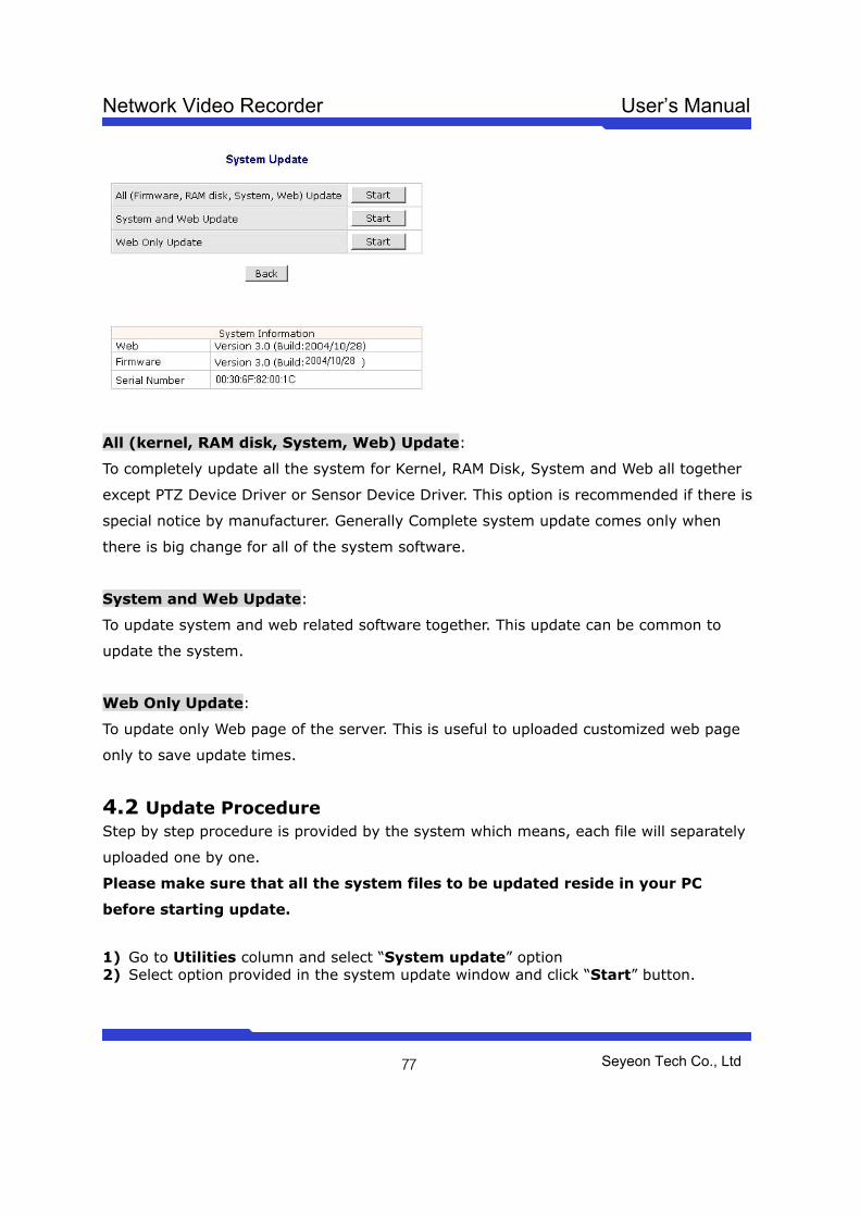
Network Video Recorder User’s Manual
Seyeon Tech Co., Ltd
77
All (kernel, RAM disk, System, Web) Update:
To completely update all the system for Kernel, RAM Disk, System and Web all together
except PTZ Device Driver or Sensor Device Driver. This option is recommended if there is
special notice by manufacturer. Generally Complete system update comes only when
there is big change for all of the system software.
System and Web Update:
To update system and web related software together. This update can be common to
update the system.
Web Only Update:
To update only Web page of the server. This is useful to uploaded customized web page
only to save update times.
4.2 Update Procedure Step by step procedure is provided by the system which means, each file will separately
uploaded one by one.
Please make sure that all the system files to be updated reside in your PC
before starting update.
1) Go to Utilities column and select “System update” option 2) Select option provided in the system update window and click “Start” button.
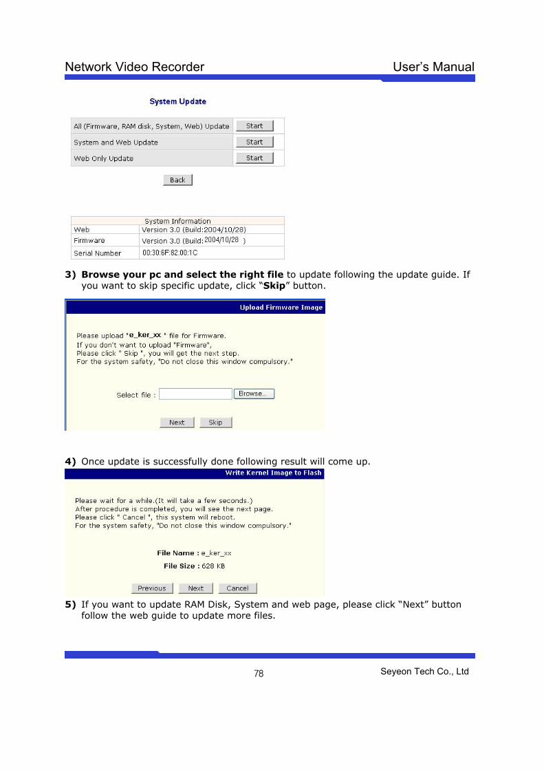
Network Video Recorder User’s Manual
Seyeon Tech Co., Ltd
78
3) Browse your pc and select the right file to update following the update guide. If
you want to skip specific update, click “Skip” button.
4) Once update is successfully done following result will come up.
5) If you want to update RAM Disk, System and web page, please click “Next” button
follow the web guide to update more files.
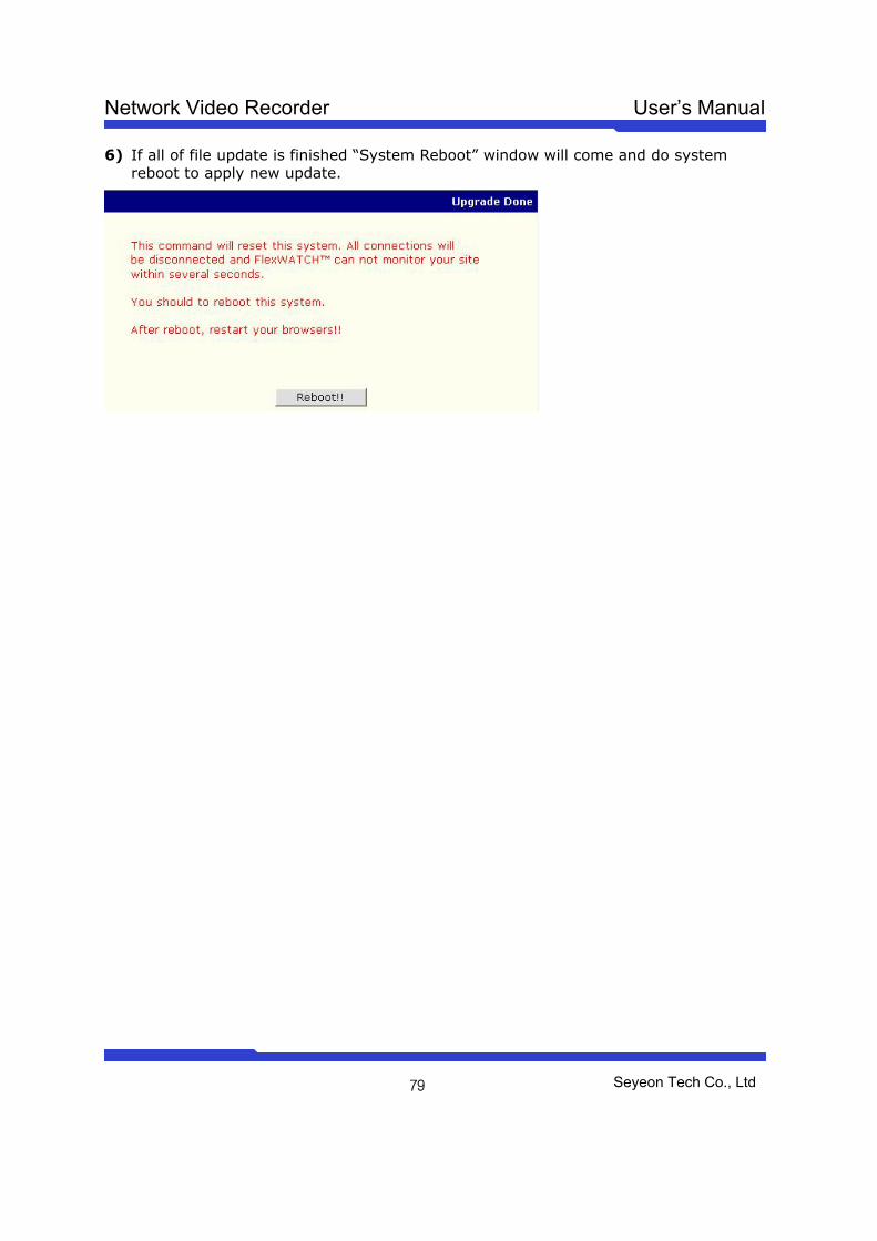
Network Video Recorder User’s Manual
Seyeon Tech Co., Ltd
79
6) If all of file update is finished “System Reboot” window will come and do system reboot to apply new update.
Network Video Recorder User’s Manual
Seyeon Tech Co., Ltd
80
Warranty
Product Network Video Server
Model FlexWATCHTM 5000 S/N
Seyeon Tech Ltd. Warranty 1 year Limited A/S
+82-2-3017-0866
Seyeon Tech Co., Ltd.
TEL : +82-2-3017-0855
FAX : +82-2-3017-0843
http://www.seyeon.co.kr
http://ww.flexwatch.com
A/S Center:
Tel : +82-2-3017-0855
Fax: +82-2-3017-0843