Embed Size (px)
Citation preview
M. Mohr F.W. FuchsCSI for fuel cells
Nordic Workshop on Power and Industrial Electronics
NORPIE 2004 Trondheim, 14-16 June
Dimensioning of a Current Source Inverter for the Feed-in of Electrical Energy from Fuel Cells to the Mains
Malte Mohr, Friedrich W. Fuchs
Chair for Power Electronics and Electrical Drives
Christian-Albrechts-Universität zu Kiel, Germany
M. Mohr F.W. FuchsCSI for fuel cells
Outline
1. Introduction
2. Fuel cell 2. Fuel cell
3. Demands on the inverter
3.1 Current source inverter (CSI)
3.2 Dimensioning/optimisation
3.3 Laboratory test setup
4. Conclusion
M. Mohr F.W. FuchsCSI for fuel cells
1. Introduction
• Fuel cells convert chemical energy directly into electrical energy.
• Fuel cells have a high electrical efficiency.• Application in decentral power generation.• Fuel cells deliver dc-current.• Power electronics converts it into ac-current.• A current source inverter fulfils the
requirements for operation at fuel cells.

M. Mohr F.W. FuchsCSI for fuel cells
2. Fuel cell
V [V]
J [A/cm2]
M. Mohr F.W. FuchsCSI for fuel cells
2. Fuel cell
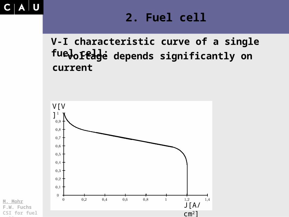
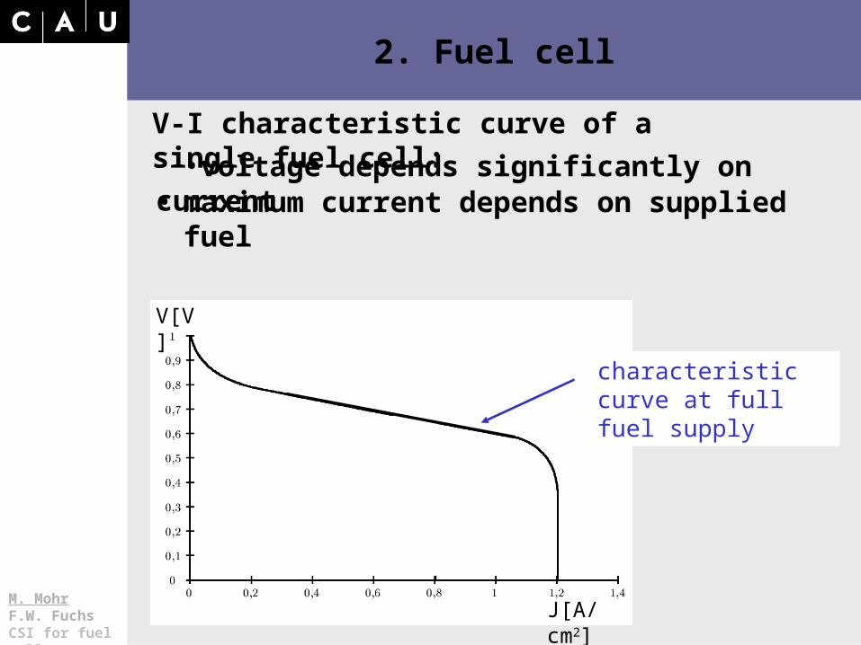
V-I characteristic curve of a single fuel cell:
•voltage depends significantly on current
V[V]
J[A/cm2]
M. Mohr F.W. FuchsCSI for fuel cells
2. Fuel cell
characteristic curve at full fuel supply
V-I characteristic curve of a single fuel cell:
•voltage depends significantly on current• maximum current depends on supplied fuel
J[A/cm2]
V[V]

M. Mohr F.W. FuchsCSI for fuel cells
2. Fuel cell
characteristic curve at partial fuel supply
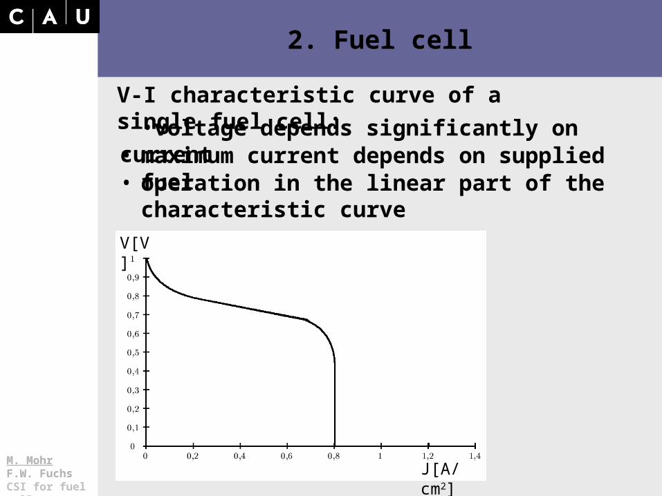
V-I characteristic curve of a single fuel cell:
•voltage depends significantly on current• maximum current depends on supplied fuel
J[A/cm2]
V[V]
M. Mohr F.W. FuchsCSI for fuel cells
2. Fuel cell
V-I characteristic curve of a single fuel cell:
•voltage depends significantly on current• maximum current depends on supplied fuel• operation in the linear part of the characteristic
curve
J[A/cm2]
V[V]

M. Mohr F.W. FuchsCSI for fuel cells
2. Fuel cell
operating point at partial load
operating point at full load
J[A/cm2]
V-I characteristic curve of a single fuel cell:
•voltage depends significantly on current• maximum current depends on supplied fuel• operation in the linear part of the characteristic
curve
V[V]
M. Mohr F.W. FuchsCSI for fuel cells
3. Demands on the inverter
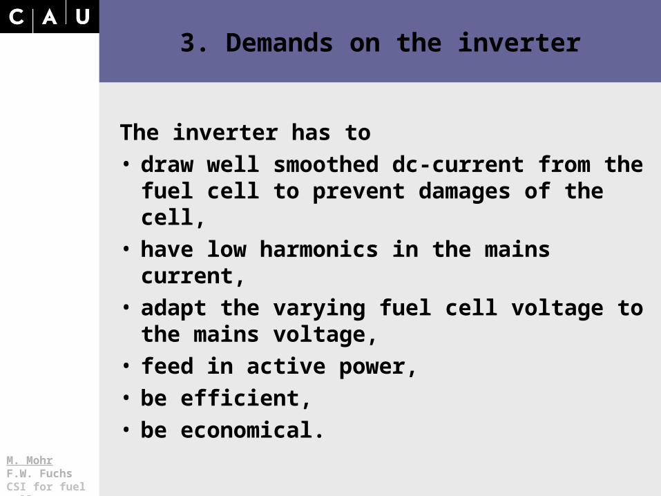
The inverter has to• draw well smoothed dc-current from the fuel cell
to prevent damages of the cell,• have low harmonics in the mains current,• adapt the varying fuel cell voltage to the mains
voltage,• feed in active power,• be efficient,• be economical.
M. Mohr F.W. FuchsCSI for fuel cells
3.1 Current source inverter (CSI)
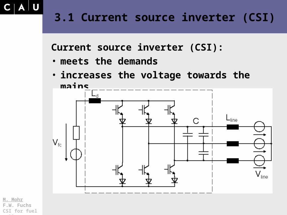
Current source inverter (CSI):• meets the demands• increases the voltage towards the mains
M. Mohr F.W. FuchsCSI for fuel cells
3.1 Current source inverter (CSI)
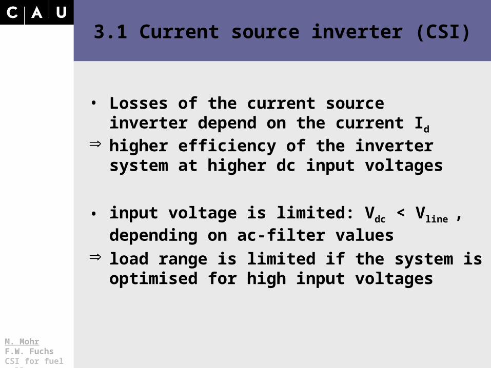
higher efficiency of the inverter system at higher dc input voltages
• input voltage is limited: Vdc < Vline , depending on ac-filter values
load range is limited if the system is optimised for high input voltages
• Losses of the current source inverter depend on the current Id
M. Mohr F.W. FuchsCSI for fuel cells
3.2 Dimensioning/optimisation
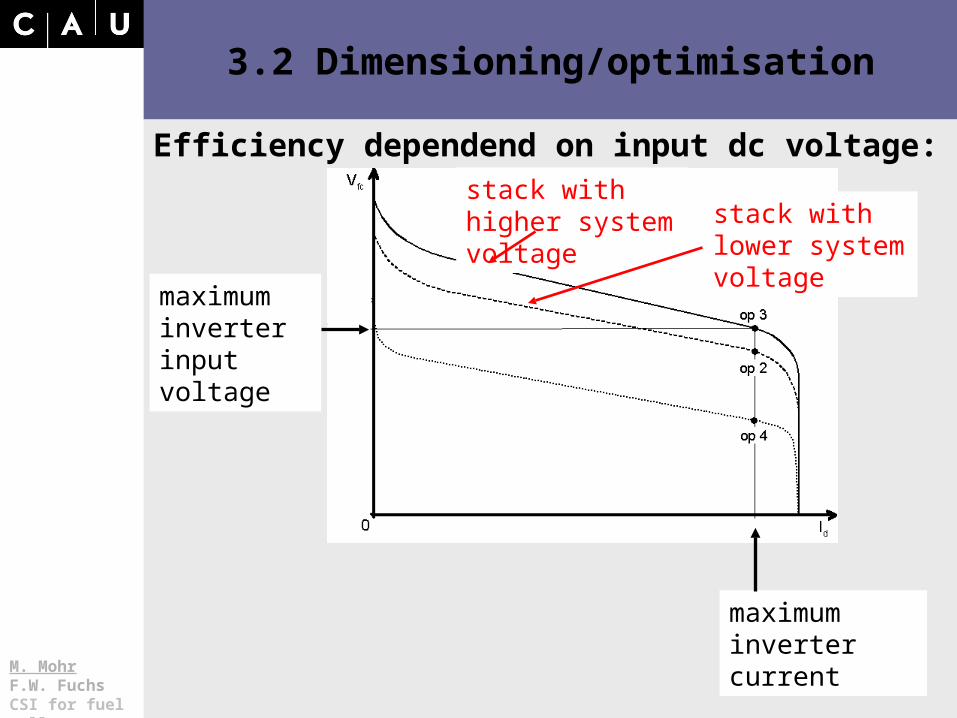
Efficiency dependend on input dc voltage:stack with higher system voltage stack with lower
system voltage
maximum inverter current
maximum inverter input voltage
M. Mohr F.W. FuchsCSI for fuel cells
3.2 Dimensioning/optimisation
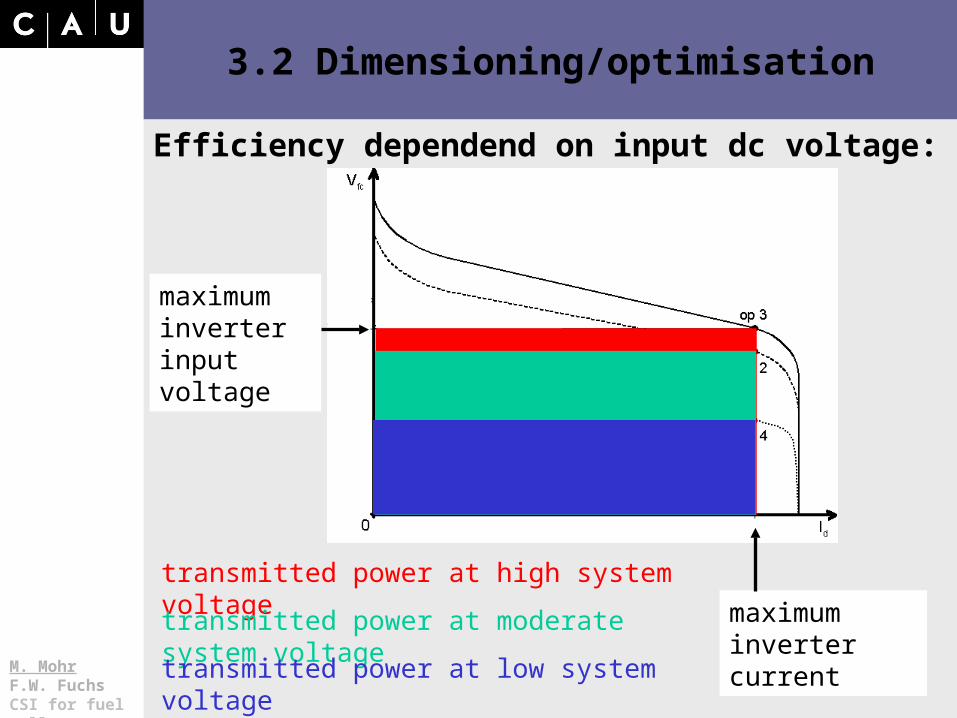
Efficiency dependend on input dc voltage:
transmitted power at high system voltage
transmitted power at moderate system voltage maximum inverter current
maximum inverter input voltage
transmitted power at low system voltage
M. Mohr F.W. FuchsCSI for fuel cells
3.2 Dimensioning/optimisation
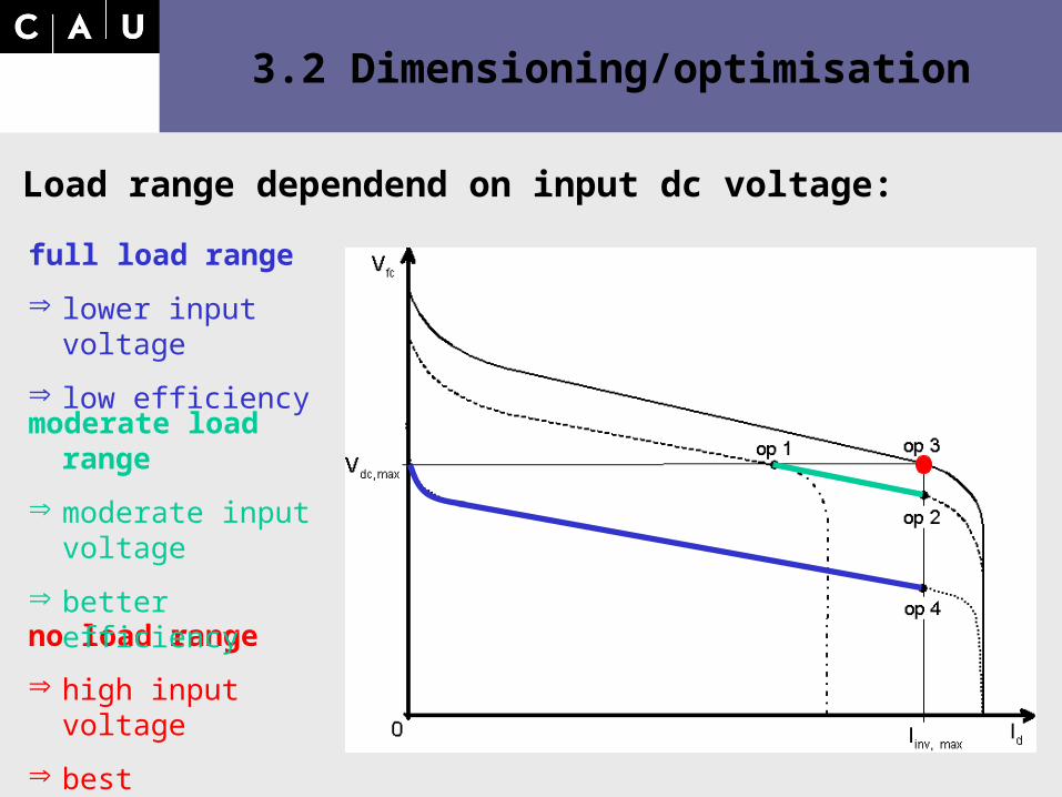
Load range dependend on input dc voltage:
full load range
lower input voltage
low efficiency
no load range
high input voltage
best efficiency
moderate load range
moderate input voltage
better efficiency
M. Mohr F.W. FuchsCSI for fuel cells
3.2 Dimensioning/optimisation
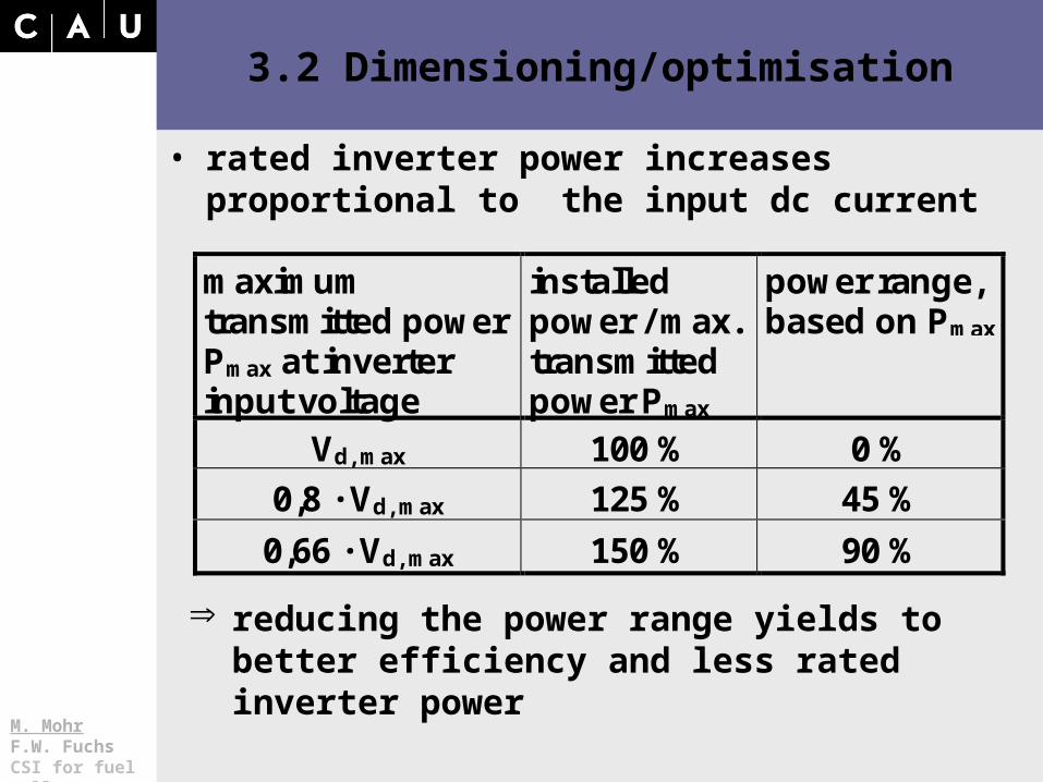
• rated inverter power increases proportional to the input dc current
maximumtransmitted powerPmax at inverterinput voltage
installedpower / max.transmittedpower Pmax
power range,based on Pmax
Vd, max 100 % 0 %
0,8 · Vd, max 125 % 45 %
0,66 · Vd, max 150 % 90 %
reducing the power range yields to better efficiency and less rated inverter power
M. Mohr F.W. FuchsCSI for fuel cells
3.2 Dimensioning/optimisation
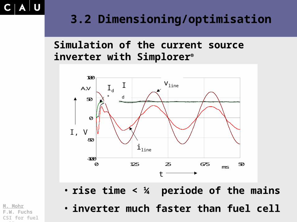
Simulation of the current source inverter with Simplorer®
Id*, Id,
Vline/5, iline
t
12.5 25 67.5 50
A, V
ms
-100
-50
50
100
0
0
Id* Id Vline
iline
• rise time < ¼ periode of the mains
• inverter much faster than fuel cell
vline
t
Id* Id
iline
I, V
M. Mohr F.W. FuchsCSI for fuel cells
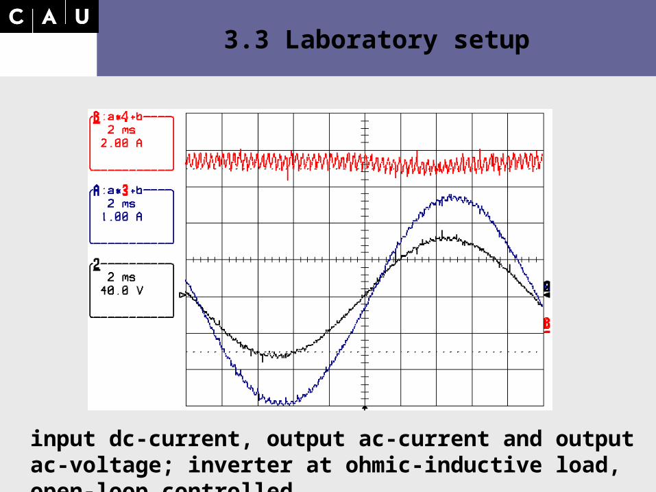
3.3 Laboratory setup
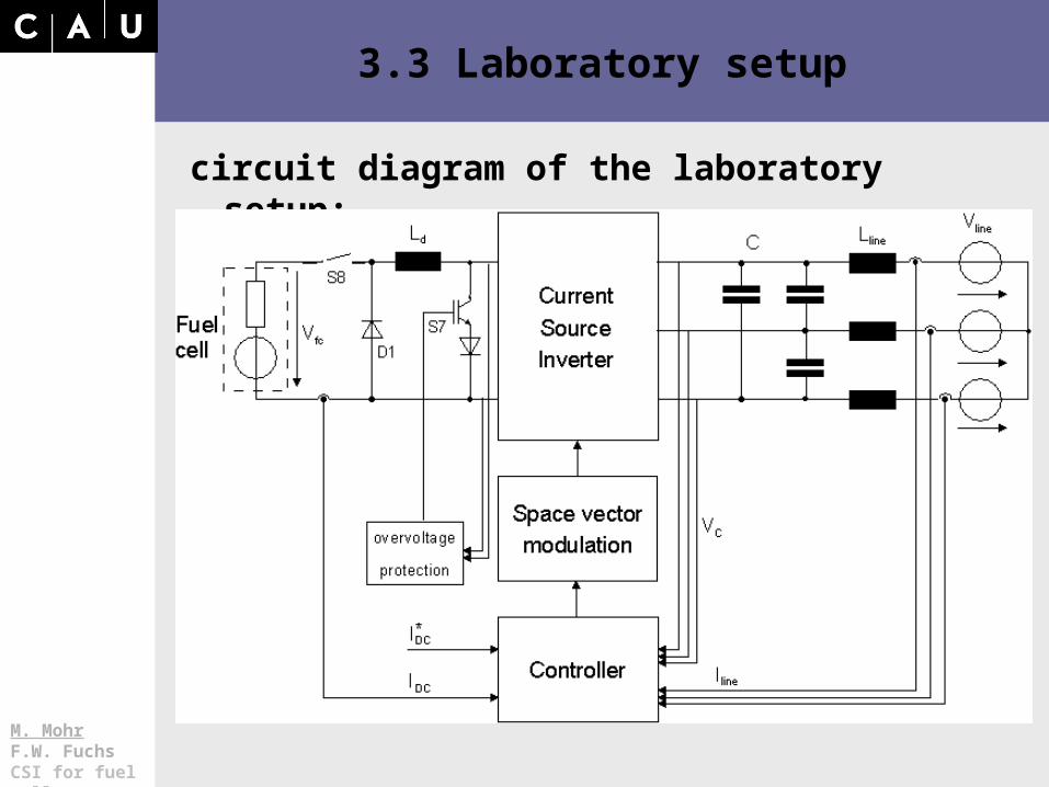
circuit diagram of the laboratory setup:
M. Mohr F.W. FuchsCSI for fuel cells
3.3 Laboratory setup
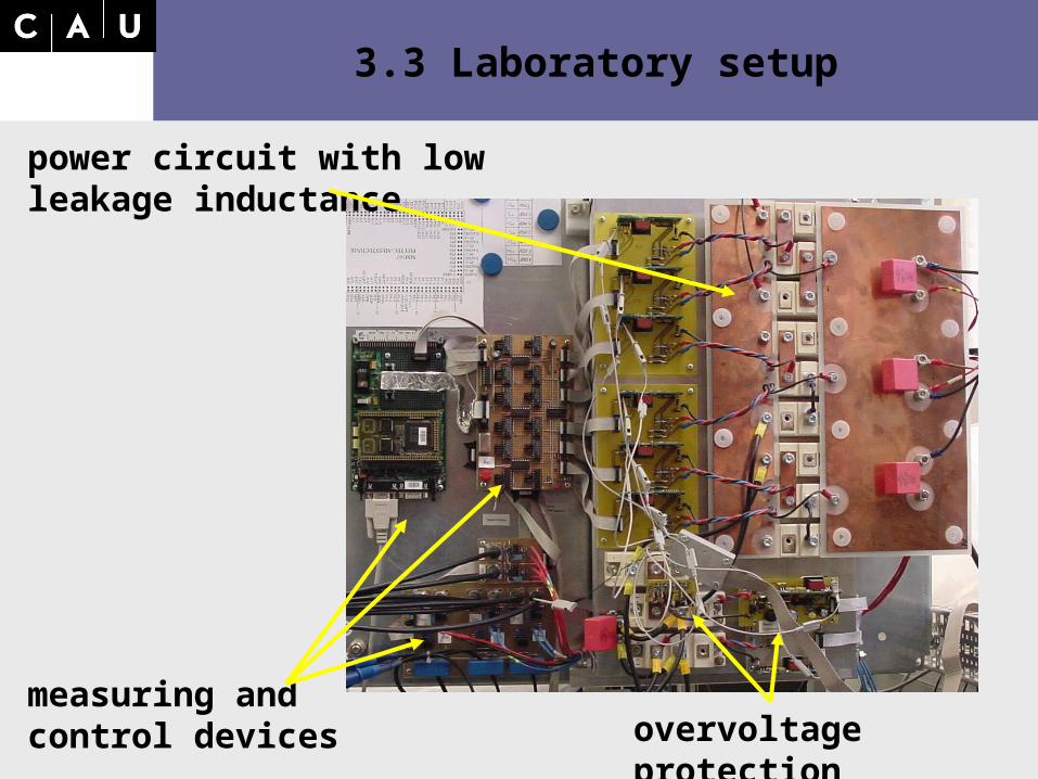
measuring and control devices
power circuit with low leakage inductance
overvoltage protection
M. Mohr F.W. FuchsCSI for fuel cells
3.3 Laboratory setup
input dc-current, output ac-current and output ac-voltage; inverter at ohmic-inductive load, open-loop controlled
M. Mohr F.W. FuchsCSI for fuel cells
4. Conclusion
The current source inverter• is suitable to convert electrical energy from fuel
cells to feed in the mains,• has poor utilisation and poor efficiency at low
dc-input voltages.
• Limitation of power range enhances efficiency and inverter utilisation.
• In principle the CSI is suited for higher system voltages and therefore higher power ratings.
M. Mohr F.W. FuchsCSI for fuel cells
Nordic Workshop on Power and Industrial Electronics
NORPIE 2004, 14-16 June
Dimensioning of a Current Source Inverter for the Feed-in of Electrical Energy from Fuel Cells to the Mains
Malte Mohr, Friedrich W. Fuchs
Chair for Power Electronics and Electrical Drives
Christian-Albrechts-Universität zu Kiel, Germany