Embed Size (px)
Citation preview
M-7026
User Manual Warranty
All products manufactured by ICP DAS are under warranty regarding defective materials for a period of one year from the date of delivery to the original purchaser.
Warning ICP DAS assumes no liability for damages resulting from the
use of this product. ICP DAS reserves the right to change this manual at any time without notification. The information furnished by ICP DAS is believed to be accurate and reliable. However, no responsibility is assumed by ICP DAS for its use, nor for any infringements of patents or other rights of third parties resulting from its use.
Copyright Copyright ©2013 ICP DAS. All rights reserved.
Trademarks Names are used for identification purposes only and may be
registered trademarks of their respective companies.
Date: 2014/09/01
M-7026 User Manual Rev: 1.3 Date: 2014/09/01 1
Table of Contents
1. Introduction.........................................................................................6
1.1 Applications ................................................................................. 7
1.2 More Information......................................................................... 7
1.3 Pin Assignments ......................................................................... 8
1.4 Specifications .............................................................................. 9
1.4.1 System Specifications ..................................................... 9
1.4.2 I/O Specifications ........................................................... 10
1.5 Block Diagram ........................................................................... 12
1.6 Application Wiring ..................................................................... 13
1.7 Default Settings......................................................................... 14
1.8 Calibration .................................................................................. 15
1.8.1 Analog Input .................................................................... 15
1.8.2 Analog Output ................................................................. 16
1.9 Configuration ............................................................................. 17
1.9.1 Baud Rate Settings (CC)............................................... 17
1.9.2 Analog Input Type Code Settings (TT) ....................... 17
1.9.3 Data Format Settings (FF) ............................................ 18
1.9.4 Analog Input Type Codes and Data Format .............. 19
1.9.5 Analog Output Type Codes and Data Format ........... 20
1.9.6 Analog Output Slew Rate Control................................ 20
1.10 M-7000 Notes ............................................................................ 21
1.10.1 Protocol Switching.......................................................... 21
1.10.2 INIT Mode ........................................................................ 22
2. DCON Protocol ................................................................................23
2.1 %AANNTTCCFF....................................................................... 30
2.2 #**................................................................................................ 32
2.3 #AA.............................................................................................. 33
2.4 #AAN........................................................................................... 35
2.5 #AAN(Data) ............................................................................... 36
2.6 $AA0 ........................................................................................... 38
2.7 $AA0N ........................................................................................ 40
2.8 $AA1 ........................................................................................... 42
2.9 $AA1N ........................................................................................ 44
2.10 $AA2 ........................................................................................... 46
2.11 $AA3NVV ................................................................................... 48
2.12 $AA4 ........................................................................................... 50
M-7026 User Manual Rev: 1.3 Date: 2014/09/01 2
2.13 $AA4N ........................................................................................ 52
2.14 $AA5 ........................................................................................... 53
2.15 $AA5VV ...................................................................................... 54
2.16 $AA6 ........................................................................................... 55
2.17 $AA6N ........................................................................................ 56
2.18 $AA7CiRrr .................................................................................. 58
2.19 $AA7N ........................................................................................ 60
2.20 $AA8Ci ....................................................................................... 62
2.21 $AA8N ........................................................................................ 64
2.22 $AA9N ........................................................................................ 66
2.23 $AA9NTS ................................................................................... 68
2.24 $AAB ........................................................................................... 70
2.25 $AABO........................................................................................ 72
2.26 $AAC........................................................................................... 73
2.27 $AAE ........................................................................................... 74
2.28 $AAEnn ...................................................................................... 75
2.29 $AAF ........................................................................................... 76
2.30 $AAI ............................................................................................ 77
2.31 $AALS......................................................................................... 78
2.32 $AAM .......................................................................................... 80
2.33 $AAP ........................................................................................... 81
2.34 $AAPN ........................................................................................ 82
2.35 $AAS1......................................................................................... 84
2.36 ~**................................................................................................ 85
2.37 ~AA0 ........................................................................................... 86
2.38 ~AA1 ........................................................................................... 88
2.39 ~AA2 ........................................................................................... 89
2.40 ~AA3ETT.................................................................................... 91
2.41 ~AA4 ........................................................................................... 93
2.42 ~AA4N ........................................................................................ 95
2.43 ~AA5N ........................................................................................ 97
2.44 ~AA5PPSS ................................................................................ 99
2.45 ~AAD......................................................................................... 101
2.46 ~AADVV ................................................................................... 103
2.47 ~AAEV ...................................................................................... 105
2.48 ~AAI .......................................................................................... 107
2.49 ~AAO(Data) ............................................................................. 108
2.50 ~AARD...................................................................................... 109
M-7026 User Manual Rev: 1.3 Date: 2014/09/01 3
2.51 ~AARDTT................................................................................. 110
2.52 ~AATnn .................................................................................... 111
2.53 @AACECi ................................................................................ 112
2.54 @AACH .................................................................................... 114
2.55 @AACHCi ................................................................................ 115
2.56 @AACHi ................................................................................... 117
2.57 @AACL..................................................................................... 119
2.58 @AACLCi................................................................................. 120
2.59 @AACLi.................................................................................... 122
2.60 @AADACi ................................................................................ 124
2.61 @AADI...................................................................................... 126
2.62 @AADODD .............................................................................. 128
2.63 @AAEATCi .............................................................................. 130
2.64 @AAHI(Data)Ci....................................................................... 132
2.65 @AALO(Data)Ci ..................................................................... 134
2.66 @AARACi ................................................................................ 136
2.67 @AARAO ................................................................................. 138
2.68 @AARECi ................................................................................ 140
2.69 @AARH .................................................................................... 142
2.70 @AARHCi ................................................................................ 144
2.71 @AARHi ................................................................................... 146
2.72 @AARL..................................................................................... 148
2.73 @AARLCi................................................................................. 150
2.74 @AARLi.................................................................................... 152
3. Modbus RTU Protocol ..................................................................154
3.1 Function 02 (0x02) - Read the Status of the Digital Input Channels........................................................................................... 155
3.2 Function 04 (0x04) - Read the Analog Input Channels .... 156
3.3 Function 05 (0x05) - Write to a Single Digital Output Channel............................................................................................. 157
3.4 Function 70 (0x46) - Read/Write the Module Settings ..... 158
3.4.1 Sub-function 00 (0x00) - Read the Name of the Module............................................................................ 159
3.4.2 Sub-function 04 (0x04) - Set the Address of the Module............................................................................ 160
3.4.3 Sub-function 05 (0x05) - Read the Communication Protocol .......................................................................... 161
M-7026 User Manual Rev: 1.3 Date: 2014/09/01 4
3.4.4 Sub-function 06 (0x06) - Set the Communication Protocol .......................................................................... 162
3.4.5 Sub-function 07 (0x07) - Read the Analog Input Type Code ..................................................................... 164
3.4.6 Sub-function 08 (0x08) - Set the Analog Input Type Code ............................................................................... 165
3.4.7 Sub-function 32 (0x20) - Read the Firmware Version Information..................................................................... 166
3.4.8 Sub-function 37 (0x25) - Read whether an Analog Input Channel is Enabled or Disabled ...................... 167
3.4.9 Sub-function 38 (0x26) – Enable or Disable the Analog Input Channels ................................................ 168
3.4.10 Sub-function 41 (0x29) - Read the Miscellaneous Settings .......................................................................... 169
3.4.11 Sub-function 42 (0x2A) - Write the Miscellaneous Settings .......................................................................... 170
3.5 Address Mappings.................................................................. 171
3.6 Engineering Units Data Format Table................................. 175
4. Troubleshooting .............................................................................176
4.1 Communicating with the Module .......................................... 176
4.2 Reading Data........................................................................... 176
5. Appendix .........................................................................................177
5.1 INIT Mode ................................................................................ 177
5.2 Dual Watchdog Operation ..................................................... 179
5.3 Frame Ground ......................................................................... 180
5.4 Node Information Area........................................................... 182
5.5 Reset Status ............................................................................ 183
M-7026 User Manual Rev: 1.3 Date: 2014/09/01 5
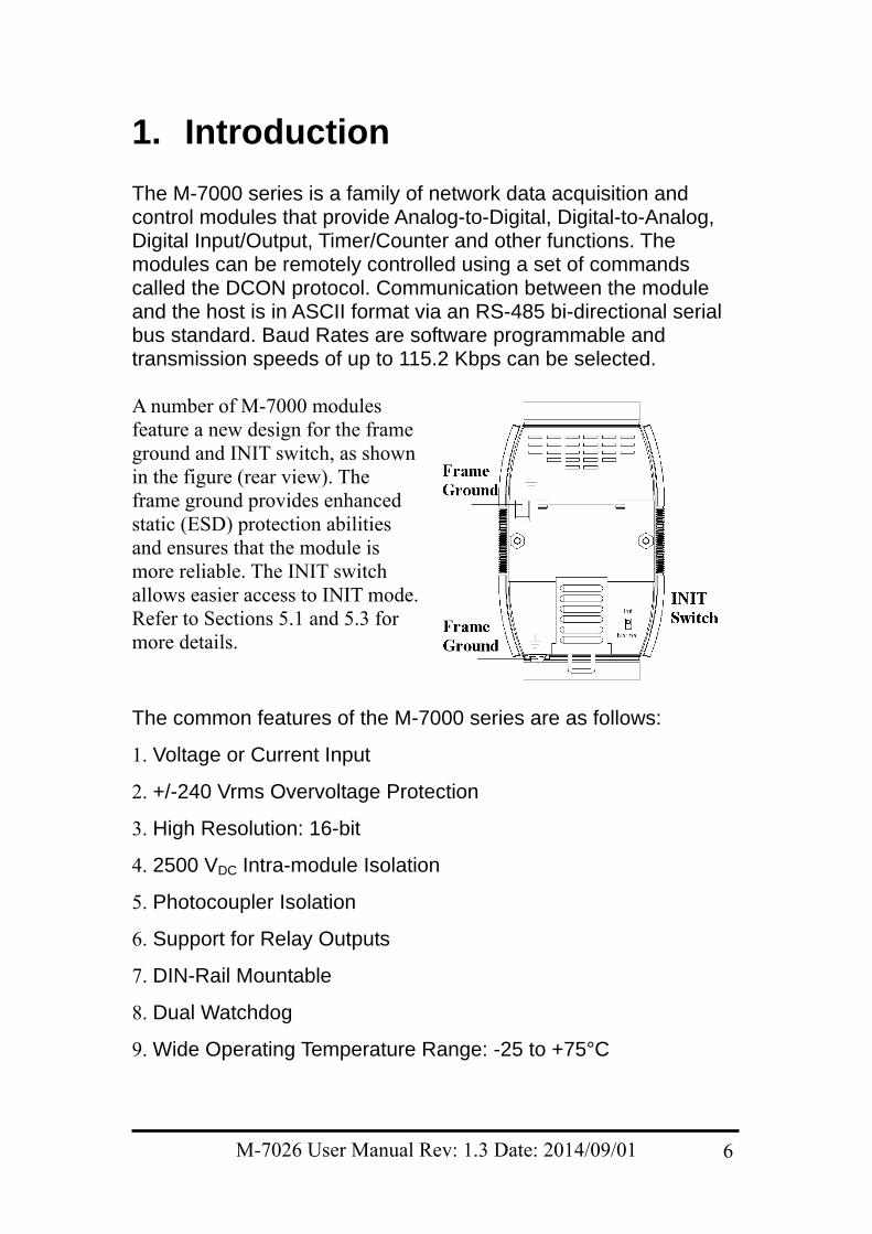
1. Introduction The M-7000 series is a family of network data acquisition and control modules that provide Analog-to-Digital, Digital-to-Analog, Digital Input/Output, Timer/Counter and other functions. The modules can be remotely controlled using a set of commands called the DCON protocol. Communication between the module and the host is in ASCII format via an RS-485 bi-directional serial bus standard. Baud Rates are software programmable and transmission speeds of up to 115.2 Kbps can be selected. A number of M-7000 modules feature a new design for the frame ground and INIT switch, as shown in the figure (rear view). The frame ground provides enhanced static (ESD) protection abilities and ensures that the module is more reliable. The INIT switch allows easier access to INIT mode. Refer to Sections 5.1 and 5.3 for more details.
The common features of the M-7000 series are as follows:
1. Voltage or Current Input
2. +/-240 Vrms Overvoltage Protection
3. High Resolution: 16-bit
4. 2500 VDC Intra-module Isolation
5. Photocoupler Isolation
6. Support for Relay Outputs
7. DIN-Rail Mountable
8. Dual Watchdog
9. Wide Operating Temperature Range: -25 to +75°C
M-7026 User Manual Rev: 1.3 Date: 2014/09/01 6
1.1 Applications
1. Building Automation
2. Factory Automation
3. Machine Automation
4. Remote Maintenance
5. Remote Diagnosis
6. Testing Equipment
1.2 More Information Refer to Chapter 1 of the M-7000 Bus Converter User Manual” for more information regarding the following: 1.1. I-7000 Overview 1.2. I-7000 Related Documentation 1.3. I-7000 Common Features 1.4. I-7000 System Network Configuration 1.5. I-7000 Dimensions
M-7026 User Manual Rev: 1.3 Date: 2014/09/01 7
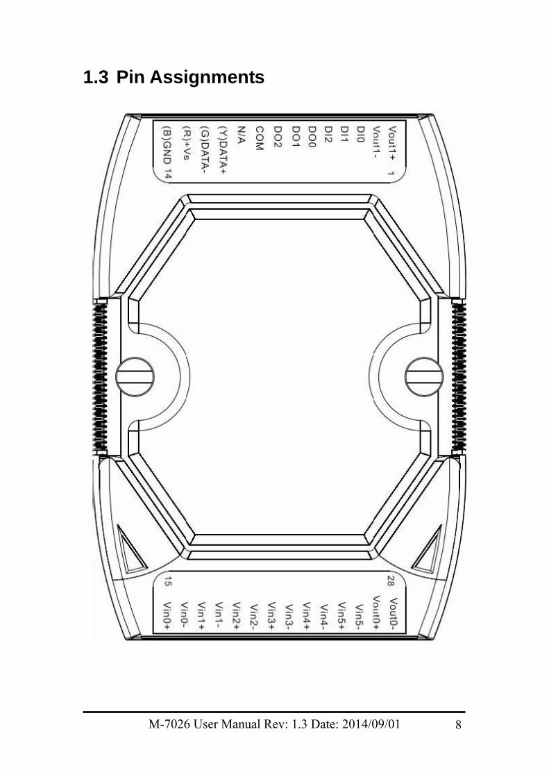
1.3 Pin Assignments
M-7026 User Manual Rev: 1.3 Date: 2014/09/01 8
1.4 Specifications
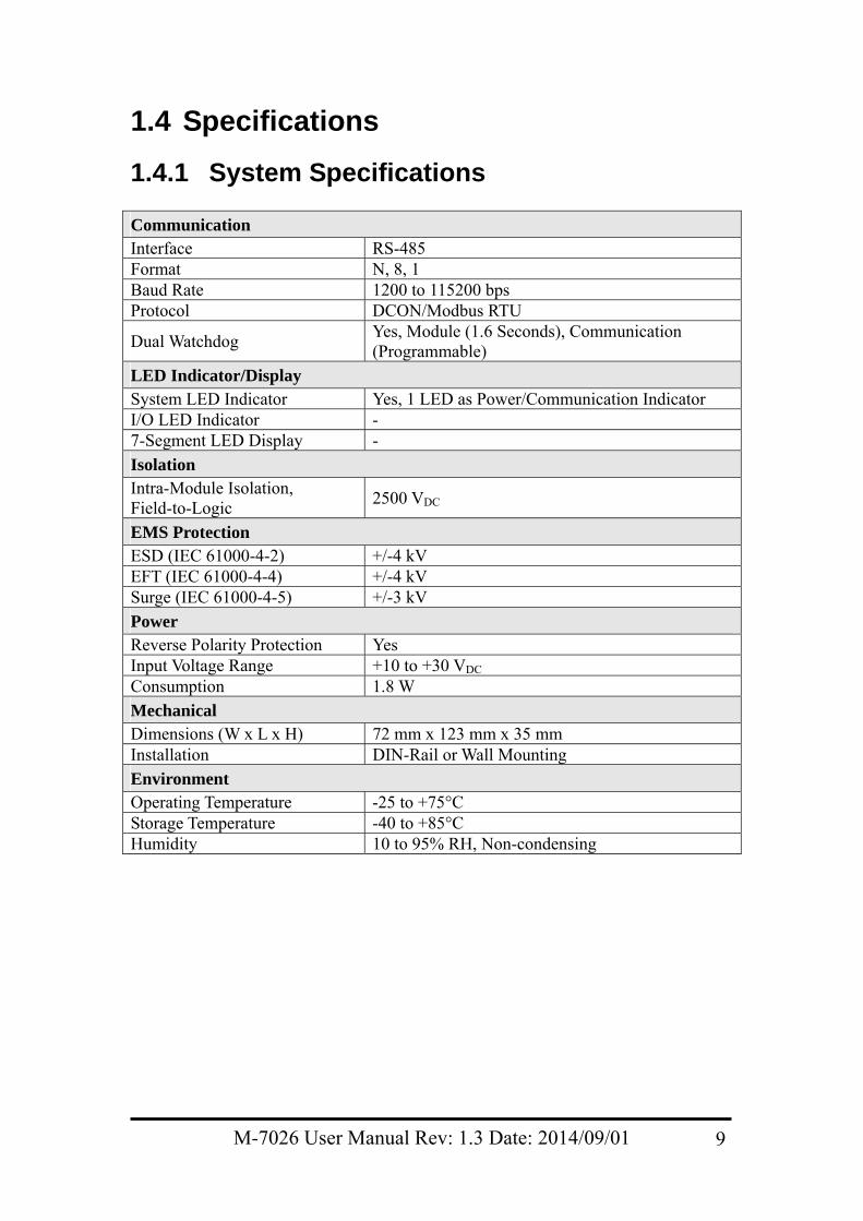
1.4.1 System Specifications Communication Interface RS-485 Format N, 8, 1 Baud Rate 1200 to 115200 bps Protocol DCON/Modbus RTU
Dual Watchdog Yes, Module (1.6 Seconds), Communication (Programmable)
LED Indicator/Display System LED Indicator Yes, 1 LED as Power/Communication Indicator I/O LED Indicator - 7-Segment LED Display -
Isolation Intra-Module Isolation, Field-to-Logic
2500 VDC
EMS Protection ESD (IEC 61000-4-2) +/-4 kV EFT (IEC 61000-4-4) +/-4 kV Surge (IEC 61000-4-5) +/-3 kV
Power Reverse Polarity Protection Yes Input Voltage Range +10 to +30 VDC Consumption 1.8 W
Mechanical Dimensions (W x L x H) 72 mm x 123 mm x 35 mm Installation DIN-Rail or Wall Mounting
Environment Operating Temperature -25 to +75°C Storage Temperature -40 to +85°C Humidity 10 to 95% RH, Non-condensing
M-7026 User Manual Rev: 1.3 Date: 2014/09/01 9
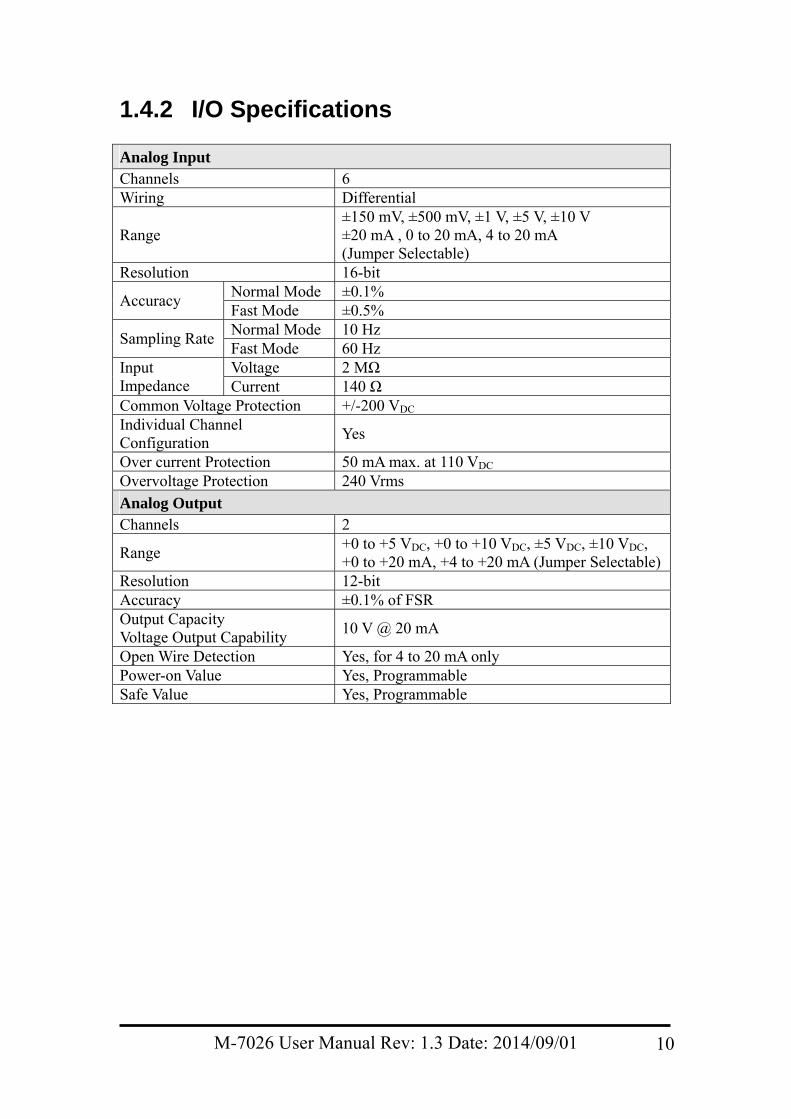
1.4.2 I/O Specifications Analog Input Channels 6 Wiring Differential
Range ±150 mV, ±500 mV, ±1 V, ±5 V, ±10 V ±20 mA , 0 to 20 mA, 4 to 20 mA (Jumper Selectable)
Resolution 16-bit Normal Mode ±0.1%
Accuracy Fast Mode ±0.5% Normal Mode 10 Hz
Sampling Rate Fast Mode 60 Hz Voltage 2 MΩ Input
Impedance Current 140 Ω Common Voltage Protection +/-200 VDC Individual Channel Configuration
Yes
Over current Protection 50 mA max. at 110 VDC Overvoltage Protection 240 Vrms
Analog Output Channels 2
Range +0 to +5 VDC, +0 to +10 VDC, ±5 VDC, ±10 VDC, +0 to +20 mA, +4 to +20 mA (Jumper Selectable)
Resolution 12-bit Accuracy ±0.1% of FSR Output Capacity Voltage Output Capability
10 V @ 20 mA
Open Wire Detection Yes, for 4 to 20 mA only Power-on Value Yes, Programmable Safe Value Yes, Programmable
M-7026 User Manual Rev: 1.3 Date: 2014/09/01 10
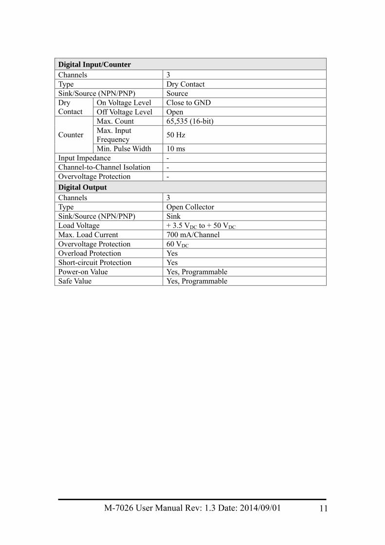
Digital Input/Counter Channels 3 Type Dry Contact Sink/Source (NPN/PNP) Source
On Voltage Level Close to GND Dry Contact Off Voltage Level Open
Max. Count 65,535 (16-bit) Max. Input Frequency
50 Hz Counter
Min. Pulse Width 10 ms Input Impedance - Channel-to-Channel Isolation - Overvoltage Protection -
Digital Output Channels 3 Type Open Collector Sink/Source (NPN/PNP) Sink Load Voltage + 3.5 VDC to + 50 VDC Max. Load Current 700 mA/Channel Overvoltage Protection 60 VDC Overload Protection Yes Short-circuit Protection Yes Power-on Value Yes, Programmable Safe Value Yes, Programmable
M-7026 User Manual Rev: 1.3 Date: 2014/09/01 11
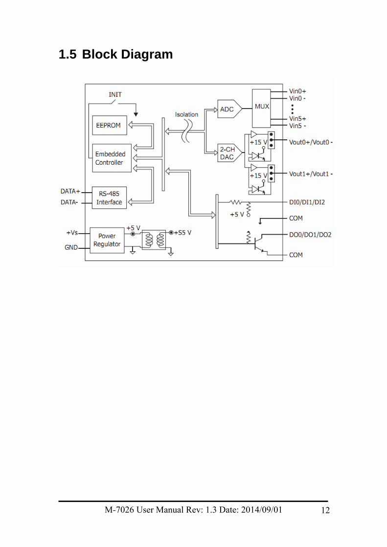
1.5 Block Diagram
M-7026 User Manual Rev: 1.3 Date: 2014/09/01 12
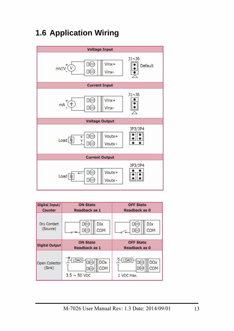
1.6 Application Wiring
M-7026 User Manual Rev: 1.3 Date: 2014/09/01 13
1.7 Default Settings The default settings for the M-7026 are: Module Address: 01 Analog Input Type: Type 08, -10 V to +10 V Analog Output Type: Type 3, -10 V to +10 V Protocol: Modbus RTU Baud Rate: 9600 bps Checksum disabled Engineering Units format Filter set at 60 Hz rejection
M-7026 User Manual Rev: 1.3 Date: 2014/09/01 14
1.8 Calibration Warning: It is not recommended that calibration be performed until the process is fully understood.
1.8.1 Analog Input The Analog Input calibration procedure is as follows:
1. Warm up the module for 30 minutes.
2. Set the Type Code to the type you wish to calibrate. Refer to Section 2.18 for details.
3. Enable calibration. Refer to Section 2.47 for details.
4. Apply the zero calibration voltage/current.
5. Send the Zero Calibration command. Refer to Section 2.8 for details.
6. Apply the span calibration voltage/current.
7. Send the Span Calibration command. Refer to Section 2.6 for details.
8. Repeat steps 3 to 7 three times. Notes:
1. The calibration voltage/current source should be connected to channel 0.
2. When calibrating Type Code 0D, the jumper for channel 0 should be set to the “current input” position.
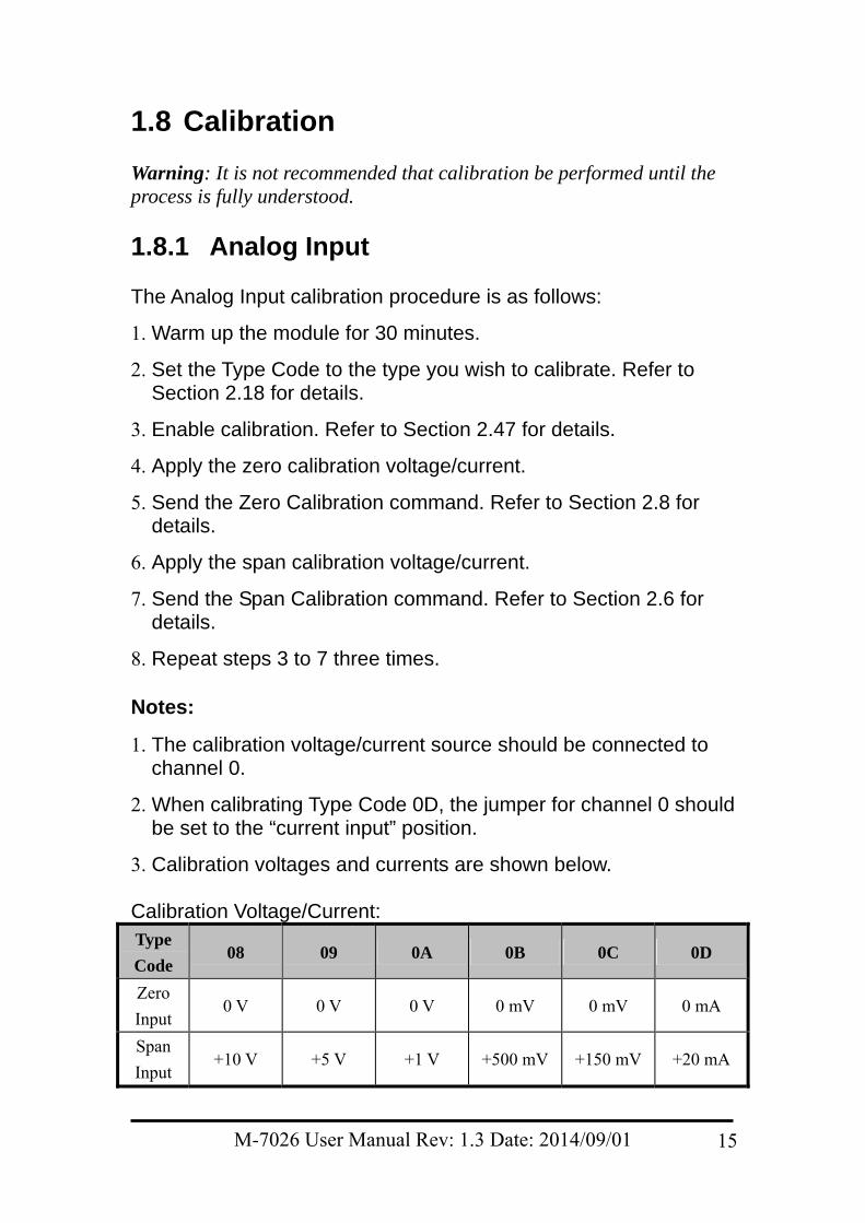
3. Calibration voltages and currents are shown below. Calibration Voltage/Current: Type
Code 08 09 0A 0B 0C 0D
Zero
Input 0 V 0 V 0 V 0 mV 0 mV 0 mA
Span
Input +10 V +5 V +1 V +500 mV +150 mV +20 mA
M-7026 User Manual Rev: 1.3 Date: 2014/09/01 15
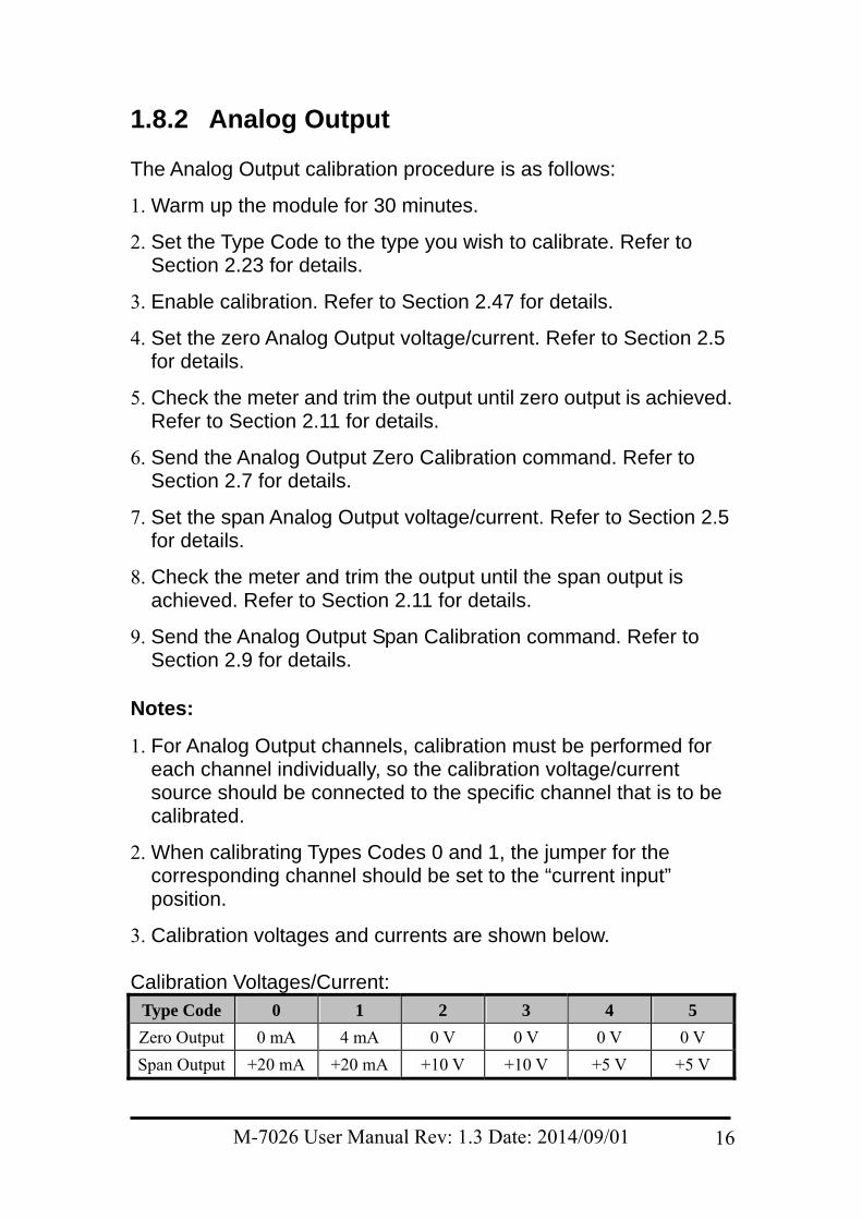
1.8.2 Analog Output The Analog Output calibration procedure is as follows:
1. Warm up the module for 30 minutes.
2. Set the Type Code to the type you wish to calibrate. Refer to Section 2.23 for details.
3. Enable calibration. Refer to Section 2.47 for details.
4. Set the zero Analog Output voltage/current. Refer to Section 2.5 for details.
5. Check the meter and trim the output until zero output is achieved. Refer to Section 2.11 for details.
6. Send the Analog Output Zero Calibration command. Refer to Section 2.7 for details.
7. Set the span Analog Output voltage/current. Refer to Section 2.5 for details.
8. Check the meter and trim the output until the span output is achieved. Refer to Section 2.11 for details.
9. Send the Analog Output Span Calibration command. Refer to Section 2.9 for details.
Notes:
1. For Analog Output channels, calibration must be performed for each channel individually, so the calibration voltage/current source should be connected to the specific channel that is to be calibrated.
2. When calibrating Types Codes 0 and 1, the jumper for the corresponding channel should be set to the “current input” position.
3. Calibration voltages and currents are shown below. Calibration Voltages/Current:
Type Code 0 1 2 3 4 5
Zero Output 0 mA 4 mA 0 V 0 V 0 V 0 V
Span Output +20 mA +20 mA +10 V +10 V +5 V +5 V
M-7026 User Manual Rev: 1.3 Date: 2014/09/01 16
1.9 Configuration
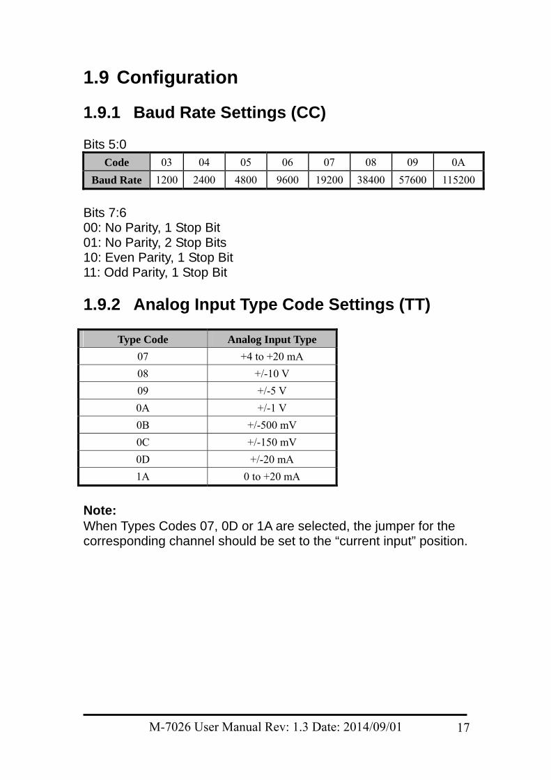
1.9.1 Baud Rate Settings (CC) Bits 5:0
Code 03 04 05 06 07 08 09 0A
Baud Rate 1200 2400 4800 9600 19200 38400 57600 115200
Bits 7:6 00: No Parity, 1 Stop Bit 01: No Parity, 2 Stop Bits 10: Even Parity, 1 Stop Bit 11: Odd Parity, 1 Stop Bit
1.9.2 Analog Input Type Code Settings (TT)
Type Code Analog Input Type
07 +4 to +20 mA
08 +/-10 V
09 +/-5 V
0A +/-1 V
0B +/-500 mV
0C +/-150 mV
0D +/-20 mA
1A 0 to +20 mA
Note: When Types Codes 07, 0D or 1A are selected, the jumper for the corresponding channel should be set to the “current input” position.
M-7026 User Manual Rev: 1.3 Date: 2014/09/01 17
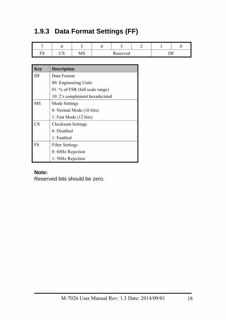
1.9.3 Data Format Settings (FF)
7 6 5 4 3 2 1 0
FS CS MS Reserved DF
Key Description
DF Data Format
00: Engineering Units
01: % of FSR (full scale range)
10: 2’s complement hexadecimal
MS Mode Settings
0: Normal Mode (16 bits)
1: Fast Mode (12 bits)
CS Checksum Settings
0: Disabled
1: Enabled
FS Filter Settings
0: 60Hz Rejection
1: 50Hz Rejection
Note: Reserved bits should be zero.
M-7026 User Manual Rev: 1.3 Date: 2014/09/01 18
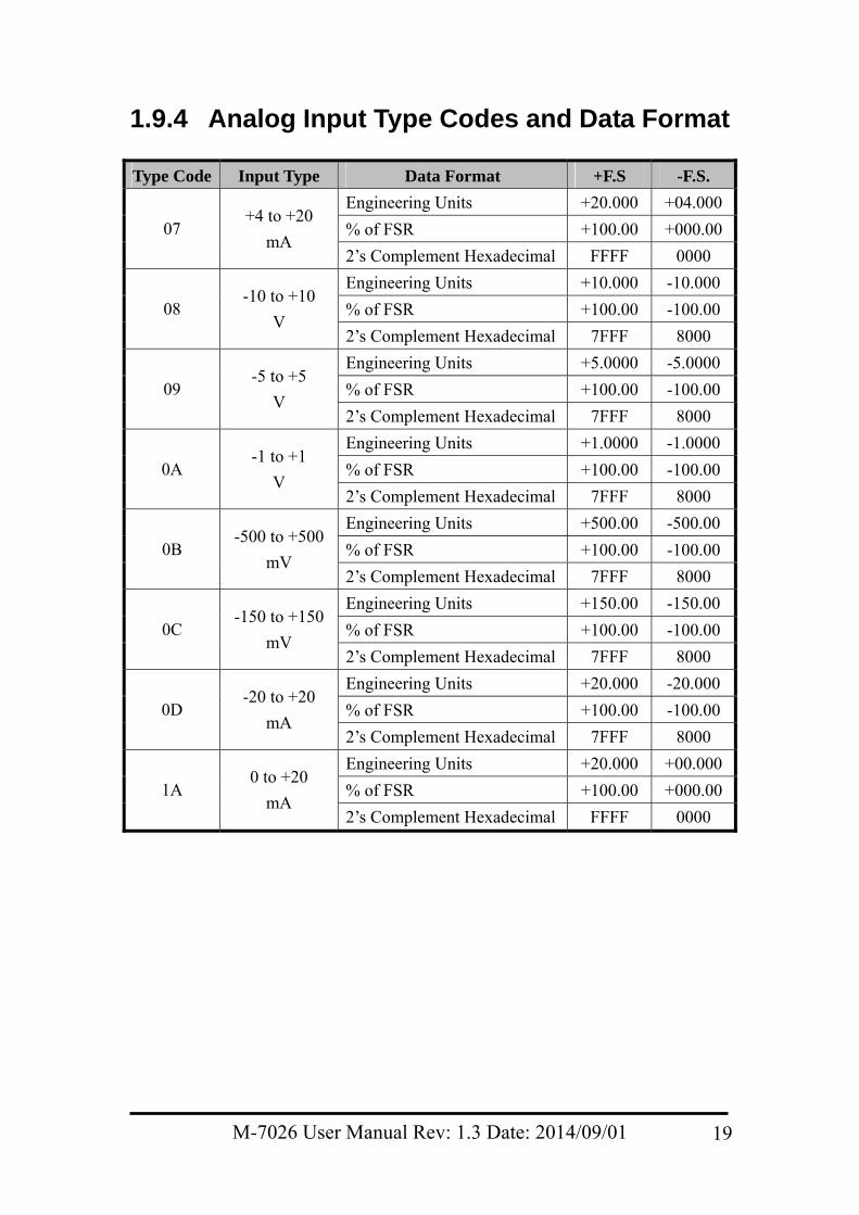
1.9.4 Analog Input Type Codes and Data Format
Type Code Input Type Data Format +F.S -F.S.
Engineering Units +20.000 +04.000
% of FSR +100.00 +000.0007 +4 to +20
mA 2’s Complement Hexadecimal FFFF 0000
Engineering Units +10.000 -10.000
% of FSR +100.00 -100.00 08 -10 to +10
V 2’s Complement Hexadecimal 7FFF 8000
Engineering Units +5.0000 -5.0000
% of FSR +100.00 -100.00 09 -5 to +5
V 2’s Complement Hexadecimal 7FFF 8000
Engineering Units +1.0000 -1.0000
% of FSR +100.00 -100.00 0A -1 to +1
V 2’s Complement Hexadecimal 7FFF 8000
Engineering Units +500.00 -500.00
% of FSR +100.00 -100.00 0B -500 to +500
mV 2’s Complement Hexadecimal 7FFF 8000
Engineering Units +150.00 -150.00
% of FSR +100.00 -100.00 0C -150 to +150
mV 2’s Complement Hexadecimal 7FFF 8000
Engineering Units +20.000 -20.000
% of FSR +100.00 -100.00 0D -20 to +20
mA 2’s Complement Hexadecimal 7FFF 8000
Engineering Units +20.000 +00.000
% of FSR +100.00 +000.001A 0 to +20
mA 2’s Complement Hexadecimal FFFF 0000
M-7026 User Manual Rev: 1.3 Date: 2014/09/01 19
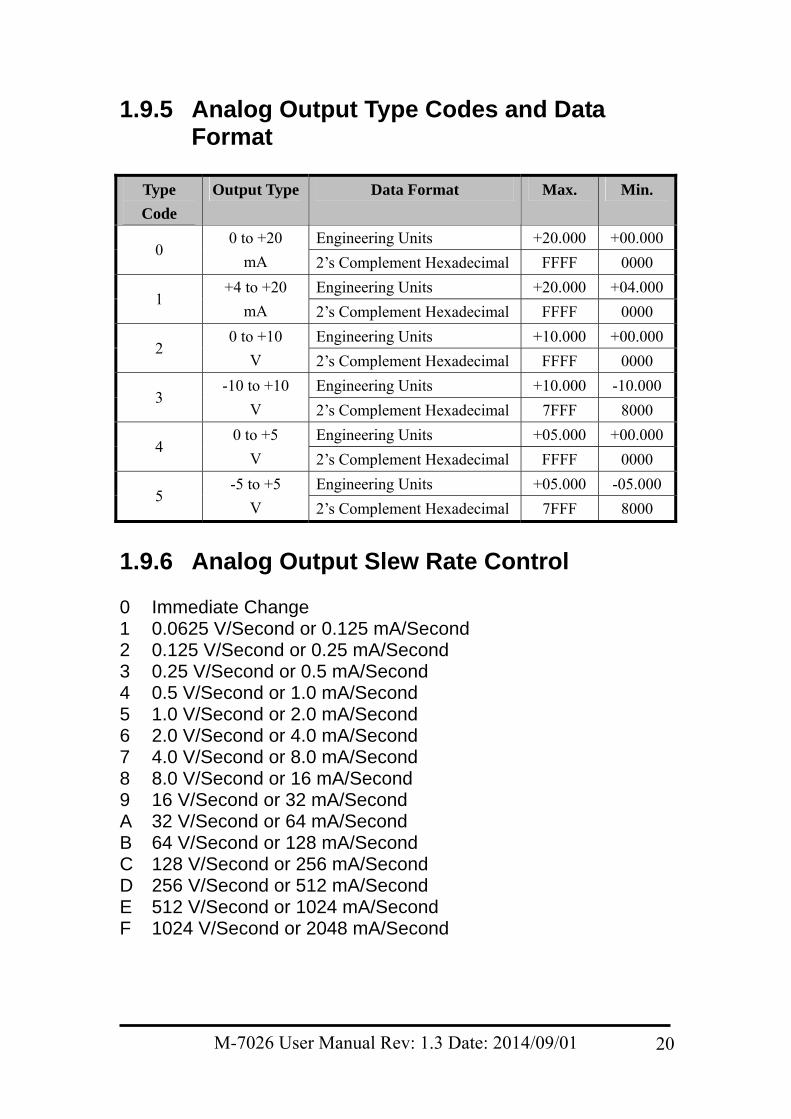
1.9.5 Analog Output Type Codes and Data Format
Type
Code
Output Type Data Format Max. Min.
Engineering Units +20.000 +00.0000
0 to +20
mA 2’s Complement Hexadecimal FFFF 0000
Engineering Units +20.000 +04.0001
+4 to +20
mA 2’s Complement Hexadecimal FFFF 0000
Engineering Units +10.000 +00.0002
0 to +10
V 2’s Complement Hexadecimal FFFF 0000
Engineering Units +10.000 -10.000 3
-10 to +10
V 2’s Complement Hexadecimal 7FFF 8000
Engineering Units +05.000 +00.0004
0 to +5
V 2’s Complement Hexadecimal FFFF 0000
Engineering Units +05.000 -05.000 5
-5 to +5
V 2’s Complement Hexadecimal 7FFF 8000
1.9.6 Analog Output Slew Rate Control 0 Immediate Change 1 0.0625 V/Second or 0.125 mA/Second 2 0.125 V/Second or 0.25 mA/Second 3 0.25 V/Second or 0.5 mA/Second 4 0.5 V/Second or 1.0 mA/Second 5 1.0 V/Second or 2.0 mA/Second 6 2.0 V/Second or 4.0 mA/Second 7 4.0 V/Second or 8.0 mA/Second 8 8.0 V/Second or 16 mA/Second 9 16 V/Second or 32 mA/Second A 32 V/Second or 64 mA/Second B 64 V/Second or 128 mA/Second C 128 V/Second or 256 mA/Second D 256 V/Second or 512 mA/Second E 512 V/Second or 1024 mA/Second F 1024 V/Second or 2048 mA/Second
M-7026 User Manual Rev: 1.3 Date: 2014/09/01 20
1.10 M-7000 Notes The main difference between the I-7000 and M-7000 series is that the M-7000 series has additional support for the Modbus RTU communication protocol, which is the default protocol of the M-7000 series. The communication Baud Rates for the Modbus RTU protocol can be in the range of 1200 bps to 115200 bps, and the parity, data and stop bits are fixed as no parity, 8 data bits and 1 stop bit. Modbus functions supported by the module are described in Chapter 3.
1.10.1 Protocol Switching To switch to the DCON protocol:
1. Uses sub-function 06h of the function 46h and set byte 8 to a value of 1. See Section 3.4.4 for details.
2. After a power-on reset, the communication protocol will be changed to DCON.
To switch to the Modbus RTU protocol:
1. Sends the $AAPN command and set N to a value of 1. Note that the slide switch on the rear side of the module should be set to INIT position, see the figure on the next page. See Section 2.34 for details.
2. After a power-on reset, the communication protocol will be changed to Modbus RTU protocol.
M-7026 User Manual Rev: 1.3 Date: 2014/09/01 21
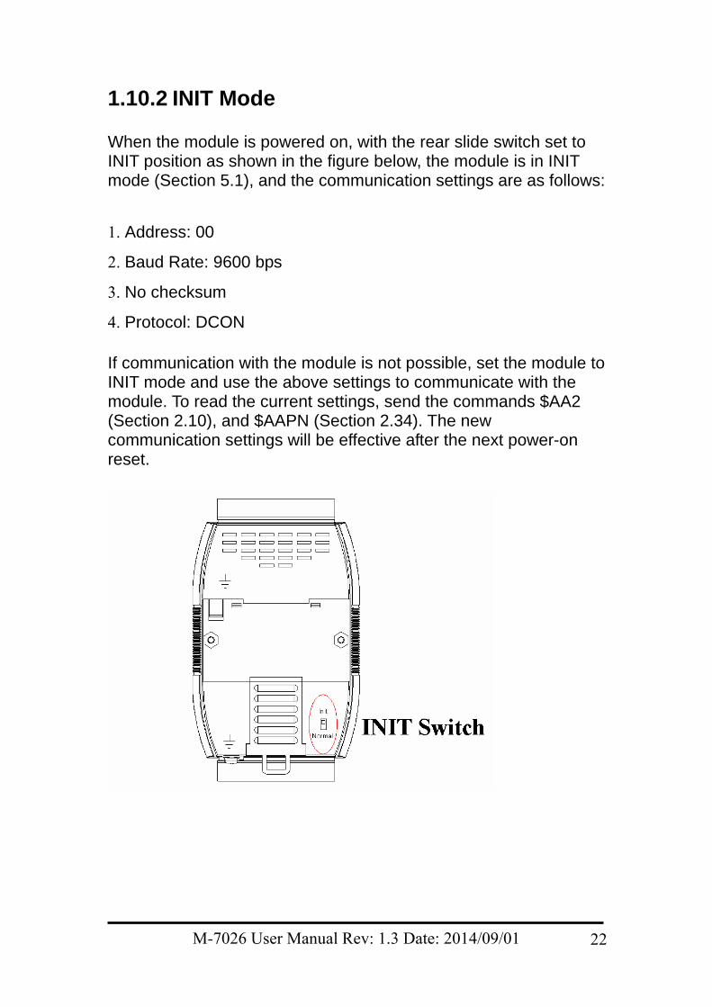
1.10.2 INIT Mode When the module is powered on, with the rear slide switch set to INIT position as shown in the figure below, the module is in INIT mode (Section 5.1), and the communication settings are as follows:
1. Address: 00
2. Baud Rate: 9600 bps
3. No checksum
4. Protocol: DCON If communication with the module is not possible, set the module to INIT mode and use the above settings to communicate with the module. To read the current settings, send the commands $AA2 (Section 2.10), and $AAPN (Section 2.34). The new communication settings will be effective after the next power-on reset.
M-7026 User Manual Rev: 1.3 Date: 2014/09/01 22
2. DCON Protocol All communication with the M-7026 module consists of commands generated by the Host and responses transmitted by the module. Each module has a unique ID number that is used for addressing purposes and is stored in non-volatile memory. The ID is set to 01 by default and can be changed by sending the appropriate user command. All commands to the modules contain the ID number as the address, meaning that only the addressed module will respond. There are two exceptions to this, however: the #** command (Section 2.2) and the ~** command (Section 2.36), which is sent to all modules, but, in these cases, the modules do not respond to the command. Command Format:
Delimiter
Character Module Address Command [CHKSUM] CR
Response Format:
Delimiter
Character Module Address Data [CHKSUM] CR
CHKSUM A 2-character checksum that is present when the
checksum setting is enabled. See Sections 2.1 and 5.1 for details.
CR End of command character, carriage return (0x0D) Calculating the Checksum:
1. Sum the ASCII codes of all the characters contained in the command/response string, except for the carriage return character (CR).
2. The checksum is equal to the sum value masked by 0FFh.
M-7026 User Manual Rev: 1.3 Date: 2014/09/01 23
Example: Command $012(CR)
1. The sum of the string = “$” + “0” + “1” + “2” = 24h+30h+31h+32h = B7h
2. Therefore the checksum is B7h, and so CHKSUM = “B7”
3. The DCON command string with the checksum = $012B7(CR) Response !01200600(CR)
1. The sum of the string = “!” + “0” + “1” + “2” + “0” + “0” + “6” + “0” + “0” = 21h+30h+31h+32h+30h+30h+36h+30h+30h = 1AAh
2. Therefore the checksum is AAh, and so CHKSUM = “AA”
3. The DCON response string with the checksum = !01200600AA(CR)
Note: All characters should be expressed in upper case.
M-7026 User Manual Rev: 1.3 Date: 2014/09/01 24
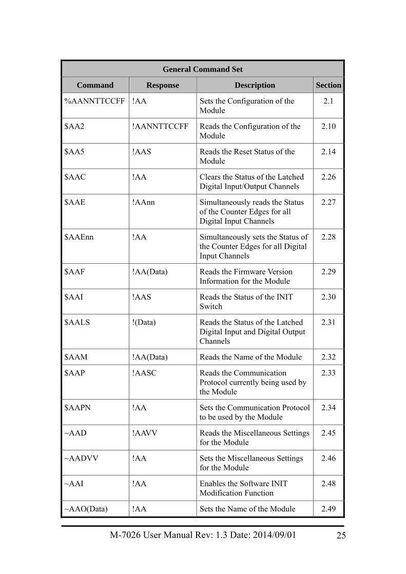
General Command Set
Command Response Description Section
%AANNTTCCFF !AA Sets the Configuration of the Module
2.1
$AA2 !AANNTTCCFF Reads the Configuration of the Module
2.10
$AA5 !AAS Reads the Reset Status of the Module
2.14
$AAC !AA Clears the Status of the Latched Digital Input/Output Channels
2.26
$AAE !AAnn Simultaneously reads the Status of the Counter Edges for all Digital Input Channels
2.27
$AAEnn !AA Simultaneously sets the Status of the Counter Edges for all Digital Input Channels
2.28
$AAF !AA(Data) Reads the Firmware Version Information for the Module
2.29
$AAI !AAS Reads the Status of the INIT Switch
2.30
$AALS !(Data) Reads the Status of the Latched Digital Input and Digital Output Channels
2.31
$AAM !AA(Data) Reads the Name of the Module 2.32
$AAP !AASC Reads the Communication Protocol currently being used by the Module
2.33
$AAPN !AA Sets the Communication Protocol to be used by the Module
2.34
~AAD !AAVV Reads the Miscellaneous Settings for the Module
2.45
~AADVV !AA Sets the Miscellaneous Settings for the Module
2.46
~AAI !AA Enables the Software INIT Modification Function
2.48
~AAO(Data) !AA Sets the Name of the Module 2.49
M-7026 User Manual Rev: 1.3 Date: 2014/09/01 25
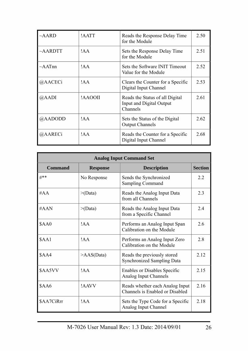
~AARD !AATT Reads the Response Delay Time for the Module
2.50
~AARDTT !AA Sets the Response Delay Time for the Module
2.51
~AATnn !AA Sets the Software INIT Timeout Value for the Module
2.52
@AACECi !AA Clears the Counter for a Specific Digital Input Channel
2.53
@AADI !AAOOII Reads the Status of all Digital Input and Digital Output Channels
2.61
@AADODD !AA Sets the Status of the Digital Output Channels
2.62
@AARECi !AA Reads the Counter for a Specific Digital Input Channel
2.68
Analog Input Command Set
Command Response Description Section
#** No Response Sends the Synchronized Sampling Command
2.2
#AA >(Data) Reads the Analog Input Data from all Channels
2.3
#AAN >(Data) Reads the Analog Input Data from a Specific Channel
2.4
$AA0 !AA Performs an Analog Input Span Calibration on the Module
2.6
$AA1 !AA Performs an Analog Input Zero Calibration on the Module
2.8
$AA4 >AAS(Data) Reads the previously stored Synchronized Sampling Data
2.12
$AA5VV !AA Enables or Disables Specific Analog Input Channels
2.15
$AA6 !AAVV Reads whether each Analog Input Channels is Enabled or Disabled
2.16
$AA7CiRrr !AA Sets the Type Code for a Specific Analog Input Channel
2.18
M-7026 User Manual Rev: 1.3 Date: 2014/09/01 26
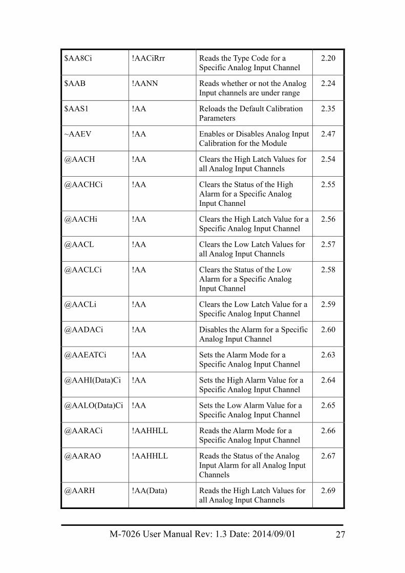
$AA8Ci !AACiRrr Reads the Type Code for a Specific Analog Input Channel
2.20
$AAB !AANN Reads whether or not the Analog Input channels are under range
2.24
$AAS1 !AA Reloads the Default Calibration Parameters
2.35
~AAEV !AA Enables or Disables Analog Input Calibration for the Module
2.47
@AACH !AA Clears the High Latch Values for all Analog Input Channels
2.54
@AACHCi !AA Clears the Status of the High Alarm for a Specific Analog Input Channel
2.55
@AACHi !AA Clears the High Latch Value for a Specific Analog Input Channel
2.56
@AACL !AA Clears the Low Latch Values for all Analog Input Channels
2.57
@AACLCi !AA Clears the Status of the Low Alarm for a Specific Analog Input Channel
2.58
@AACLi !AA Clears the Low Latch Value for a Specific Analog Input Channel
2.59
@AADACi !AA Disables the Alarm for a Specific Analog Input Channel
2.60
@AAEATCi !AA Sets the Alarm Mode for a Specific Analog Input Channel
2.63
@AAHI(Data)Ci !AA Sets the High Alarm Value for a Specific Analog Input Channel
2.64
@AALO(Data)Ci !AA Sets the Low Alarm Value for a Specific Analog Input Channel
2.65
@AARACi !AAHHLL Reads the Alarm Mode for a Specific Analog Input Channel
2.66
@AARAO !AAHHLL Reads the Status of the Analog Input Alarm for all Analog Input Channels
2.67
@AARH !AA(Data) Reads the High Latch Values for all Analog Input Channels
2.69
M-7026 User Manual Rev: 1.3 Date: 2014/09/01 27
@AARHCi !AA(Data) Reads the High Alarm Limit for a Specific Analog Input Channel
2.70
@AARHi !AA(Data) Reads the High Latch Value for a Specific Analog Input Channel
2.71
@AARL !AA(Data) Reads the Low Latch Values for all Analog Input Channels
2.72
@AARLCi !AA(Data) Reads the Low Alarm Limit for a Specific Analog Input Channel
2.73
@AARLi !AA(Data) Reads the Low Latch Value for a Specific Analog Input Channel
2.74
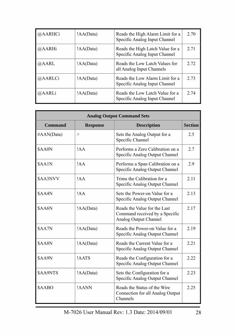
Analog Output Command Sets
Command Response Description Section
#AAN(Data) > Sets the Analog Output for a Specific Channel
2.5
$AA0N !AA Performs a Zero Calibration on a Specific Analog Output Channel
2.7
$AA1N !AA Performs a Span Calibration on a Specific Analog Output Channel
2.9
$AA3NVV !AA Trims the Calibration for a Specific Analog Output Channel
2.11
$AA4N !AA Sets the Power-on Value for a Specific Analog Output Channel
2.13
$AA6N !AA(Data) Reads the Value for the Last Command received by a Specific Analog Output Channel
2.17
$AA7N !AA(Data) Reads the Power-on Value for a Specific Analog Output Channel
2.19
$AA8N !AA(Data) Reads the Current Value for a Specific Analog Output Channel
2.21
$AA9N !AATS Reads the Configuration for a Specific Analog Output Channel
2.22
$AA9NTS !AA(Data) Sets the Configuration for a Specific Analog Output Channel
2.23
$AABO !AANN Reads the Status of the Wire Connection for all Analog Output Channels
2.25
M-7026 User Manual Rev: 1.3 Date: 2014/09/01 28
M-7026 User Manual Rev: 1.3 Date: 2014/09/01 29
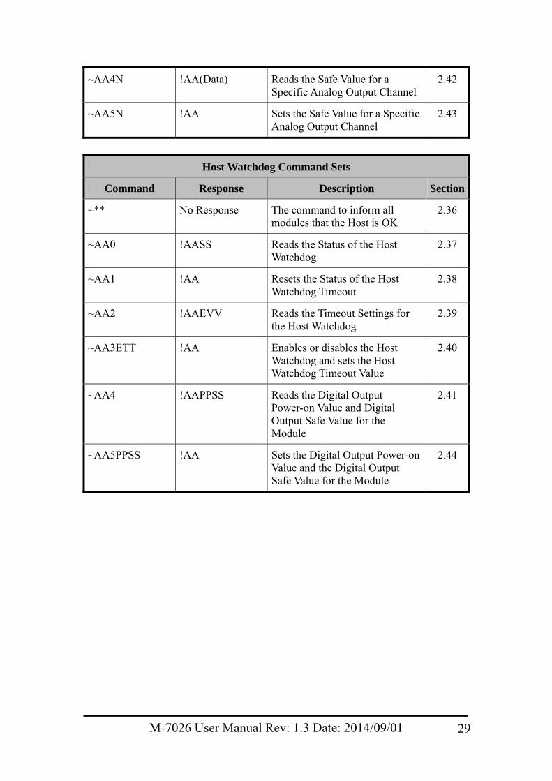
~AA4N !AA(Data) Reads the Safe Value for a Specific Analog Output Channel
2.42
~AA5N !AA Sets the Safe Value for a Specific Analog Output Channel
2.43
Host Watchdog Command Sets
Command Response Description Section
~** No Response The command to inform all modules that the Host is OK
2.36
~AA0 !AASS Reads the Status of the Host Watchdog
2.37
~AA1 !AA Resets the Status of the Host Watchdog Timeout
2.38
~AA2 !AAEVV Reads the Timeout Settings for the Host Watchdog
2.39
~AA3ETT !AA Enables or disables the Host Watchdog and sets the Host Watchdog Timeout Value
2.40
~AA4 !AAPPSS Reads the Digital Output Power-on Value and Digital Output Safe Value for the Module
2.41
~AA5PPSS !AA Sets the Digital Output Power-on Value and the Digital Output Safe Value for the Module
2.44
M-7026
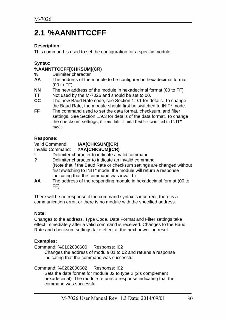
2.1 %AANNTTCCFF Description: This command is used to set the configuration for a specific module. Syntax: %AANNTTCCFF[CHKSUM](CR) % Delimiter character AA The address of the module to be configured in hexadecimal format
(00 to FF) NN The new address of the module in hexadecimal format (00 to FF) TT Not used by the M-7026 and should be set to 00. CC The new Baud Rate code, see Section 1.9.1 for details. To change
the Baud Rate, the module should first be switched to INIT* mode. FF The command used to set the data format, checksum, and filter
settings. See Section 1.9.3 for details of the data format. To change the checksum settings, the module should first be switched to INIT* mode.
Response: Valid Command: !AA[CHKSUM](CR) Invalid Command: ?AA[CHKSUM](CR) ! Delimiter character to indicate a valid command ? Delimiter character to indicate an invalid command
(Note that if the Baud Rate or checksum settings are changed without first switching to INIT* mode, the module will return a response indicating that the command was invalid.)
AA The address of the responding module in hexadecimal format (00 to FF)
There will be no response if the command syntax is incorrect, there is a communication error, or there is no module with the specified address. Note: Changes to the address, Type Code, Data Format and Filter settings take effect immediately after a valid command is received. Changes to the Baud Rate and checksum settings take effect at the next power-on reset. Examples: Command: %0102000600 Response: !02
Changes the address of module 01 to 02 and returns a response indicating that the command was successful.
Command: %0202000602 Response: !02
Sets the data format for module 02 to type 2 (2’s complement hexadecimal). The module returns a response indicating that the command was successful.
M-7026 User Manual Rev: 1.3 Date: 2014/09/01 30
M-7026
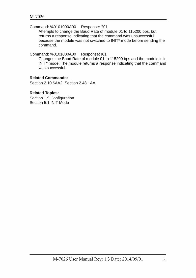
Command: %0101000A00 Response: ?01 Attempts to change the Baud Rate of module 01 to 115200 bps, but returns a response indicating that the command was unsuccessful because the module was not switched to INIT* mode before sending the command.
Command: %0101000A00 Response: !01
Changes the Baud Rate of module 01 to 115200 bps and the module is in INIT* mode. The module returns a response indicating that the command was successful.
Related Commands: Section 2.10 $AA2, Section 2.48 ~AAI Related Topics: Section 1.9 Configuration Section 5.1 INIT Mode
M-7026 User Manual Rev: 1.3 Date: 2014/09/01 31
M-7026
2.2 #** Description: This command instructs every Analog Input module to read data from every Analog Input channel and store the data in the buffer for later retrieval.
Syntax: #**[CHKSUM](CR) # Delimiter character ** The synchronized sampling command
Response: There is no response to this command. To access the data, another command, $AA4, must be sent, see Section 2.12 for details.
Examples: Command: #** No response
Sends the synchronized sampling command to all Analog Input modules. Command: $014 Response:
>011+025.12+020.45+012.78+018.97+000.00+000.00
Sends the command to read the synchronized sampling data from module 01. The module returns a response indicating that the command was successful, containing the data (in Engineering Units format) that was stored when the synchronized sampling command was last issued. The status byte of the response is 1, which means that it is the first time the synchronized sampling data has been read since the previous #** command was received.
Command: $014 Response:
>010+025.12+020.45+012.78+018.97+000.00+000.00
Sends the command to read the synchronized sampling data from module 01. The module returns a response indicating that the command was successful, containing the data (in Engineering Units format) that was stored when the synchronized sampling command was last issued. The status byte of the response is 0, which means that it is NOT the first time the synchronized sampling data has been read since the previous #** command was received.
Related Commands: Section 2.12 $AA4 Related Topics: Section 1.9.4 Analog Input Type Codes and Data Format
M-7026 User Manual Rev: 1.3 Date: 2014/09/01 32
M-7026
2.3 #AA Description: This command is used to read data from all Analog Input channels of a specified module. Syntax: #AA[CHKSUM](CR) # Delimiter character AA The address of the module to be read in hexadecimal format (00 to
FF)
Response: Valid Command: >(Data)[CHKSUM](CR) Invalid Command: ?AA[CHKSUM](CR) > Delimiter character to indicate a valid command ? Delimiter character to indicate an invalid command AA The address of the responding module in hexadecimal format (00 to
FF) (Data) The data from all Analog Input channels. See Section 1.9.4 for details
of the data format. There will be no response if the command syntax is incorrect, there is a communication error, or there is no module with the specified address. Examples: Command: #01 Response:
>+025.12+020.45+012.78+018.97+000.00+000.00
Reads data from the Analog Input channels of module 01 and returns a response indicating that the command was successful, with the data from all Analog Input channels in Engineering Units format.
Command: #02 Response: >4C532628E2D683A200000000
Reads data from the Analog Input channels of module 02 and returns a response indicating that the command was successful, with the data from all Analog Input channels in hexadecimal format.
Command: #03 Response:
>-9999.9-9999.9-9999.9-9999.9-9999.9-9999.9 Reads data from the Analog Input channels of module 03, but returns a response indicating that although the command was successful, the data is not within the valid range.
Related Commands: Section 2.1 %AANNTTCCFF, Section 2.4 #AAN, Section 2.10 $AA2, Section 2.18 $AA7CiRrr
M-7026 User Manual Rev: 1.3 Date: 2014/09/01 33

M-7026
Related Topics: Section 1.9.4 Analog Input Type Codes and Data Format
M-7026 User Manual Rev: 1.3 Date: 2014/09/01 34
M-7026
2.4 #AAN
Description: This command is used to read data from Analog Input channel N of a specified module. Syntax: #AAN[CHKSUM](CR) # Delimiter character AA The address of the module to be read in hexadecimal format (00 to
FF) N The Analog Input channel to be read, zero based (0-5)
Response: Valid Command: >(Data)[CHKSUM](CR) Invalid Command: ?AA[CHKSUM](CR) > Delimiter character to indicate a valid command ? Delimiter character to indicate an invalid command AA The address of the responding module in hexadecimal format (00 to
FF) (Data) The data from the specified Analog Input channel. See Section 1.9.4
for details of the data format. There will be no response if the command syntax is incorrect, there is a communication error, or there is no module with the specified address. Examples: Command: #032 Response: >+025.13
Reads data from Analog Input channel 2 of module 03 and returns a response indicating that the command was successful, and that the Analog Input value is +025.13 (+25.13 mV).
Command: #02F Response: ?02
Attempts to read data from Analog Input channel 15 of module 02, but returns a response indicating that the command was unsuccessful because channel 15 does not exist.
Related Commands: Section 2.1 %AANNTTCCFF, Section 2.3 #AA, Section 2.10 $AA2, Section 2.18 $AA7CiRrr Related Topics: Section 1.9.4 Analog Input Type Codes and Data Format
M-7026 User Manual Rev: 1.3 Date: 2014/09/01 35
M-7026
2.5 #AAN(Data) Description: This command is used to set the output value for Analog Output channel N of a specified module. Syntax: #AAN(Data)[CHKSUM](CR) # Delimiter character AA The address of the module to be set in hexadecimal format (00 to FF) N The Analog Output channel to be set, zero based (0-1) (Data) The Analog Output value, see Section 1.9.5 for details of the data
format. Response: Valid Command: >[CHKSUM](CR) Invalid Command: ?[CHKSUM](CR) Ignored Command:  > Delimiter character to indicate a valid command ? Delimiter character to indicate an invalid command because the
Analog Output value (Data) is out of range. The Analog Output value will be restored to the closest value defined in the range settings for the module.
! Delimiter character to indicate that the module’s Host Watchdog flag is set. The command will be ignored and the Analog Output will be set to the configured Safe value.
There will be no response if the command syntax is incorrect, there is a communication error, or there is no module with the specified address.
Examples: Command: $019000 Response: !01
Sets the output range for Analog Output channel 0 of module 01 to 0 to 20mA and sets the slew rate to change immediately and returns a response indicating that the command was successful.
Command: #010+05.000 Response: >
Sets the output value for Analog Output channel 0 of module 01 to +05.000 (5 mA) and returns a response indicating that the command was successful.
Command: #010+25.000 Response: ?
Attempts to set the output value for Analog Output channel 0 of module 01 to +25.000 (25.0 mA), but returns a response indicating that the command was unsuccessful because the output value of +25.000(+25 mA) is not within the valid range. The output value will be restored to closest value defined in the range settings for the module.
M-7026 User Manual Rev: 1.3 Date: 2014/09/01 36
M-7026
Command: #018+05.000 No Response Attempts to set the output value for Analog Output channel 8 of module 01 to +05.000 (5.0 mA), but returns no response indicating that channel 8 does not exist.
Related Commands: Section 2.1 %AANNTTCCFF, Section 2.10 $AA2, Section 2.22 $AA9N, Section 2.23 $AA9NTTS Related Topics: Section 1.9.5 Analog Output Type Codes and Data Format
M-7026 User Manual Rev: 1.3 Date: 2014/09/01 37
M-7026
2.6 $AA0 Description: This command is used to perform an Analog Input span calibration on a specified module. Syntax: $AA0[CHKSUM](CR) $ Delimiter character AA The address of the module to be calibrated in hexadecimal format (00
to FF) 0 The command to perform the Analog Input span calibration
Response: Valid Command: !AA[CHKSUM](CR) Invalid Command: ?AA[CHKSUM](CR) ! Delimiter character to indicate a valid command ? Delimiter character to indicate an invalid command AA The address of the responding module in hexadecimal format (00 to
FF) There will be no response if the command syntax is incorrect, there is a communication error, or there is no module with the specified address.
Note: The “enable calibration” command, ~AAEV (see Section 2.47), must be sent before this command is used. See Section 1.8.1 for details.
Examples: Command: $010 Response: ?01
Attempts to perform an Analog Input span calibration on module 01, but a response indicating that the command was unsuccessful is returned because the “Enable Calibration” command (~AAEV, see Section 2.47) was not sent in advance.
Command: ~01E1 Response: !01
Enables calibration on module 01 and returns a response indicating that the command was successful.
Command: $010 Response: !01
Performs an Analog Input span calibration on module 01 and returns a response indicating that the command was successful.
Related Commands: Section 2.8 $AA1, Section 2.35 $AAS1, Section 2.47 ~AAEV
M-7026 User Manual Rev: 1.3 Date: 2014/09/01 38
M-7026
Related Topics: Section 1.8.1 Analog Input Calibration
M-7026 User Manual Rev: 1.3 Date: 2014/09/01 39
M-7026
2.7 $AA0N Description: The command is used to perform an Analog Output zero calibration on Analog Output channel N of a specified module. Syntax: $AA1[CHKSUM](CR) $ Delimiter character AA The address of the module to be calibrated in hexadecimal format (00
to FF) 0 The command to perform the Analog Output zero calibration N The Analog Output channel to be calibrated, zero based (0-1) Response: Valid Command: !AA[CHKSUM](CR) Invalid Command: ?AA[CHKSUM](CR) ! Delimiter character to indicate a valid command ? Delimiter character to indicate an invalid command AA The address of the responding module in hexadecimal format (00 to
1F) There will be no response if the command syntax is incorrect, there is a communication error, or there is no module with the specified address. Note: The “enable calibration” command, ~AAEV (see Section 2.47), must be sent before this command is used. See Section 1.8.2 for details. Example: Command: ~01E1 Response: !01
Enables calibration on module 01 and returns a response indicating that the command was successful.
Command: $0101 Response: !01
Performs an Analog Output zero calibration on Analog Output channel 1 of module 01 and returns a response indicating that the command was successful.
Command: $010F Response: ?01
Attempts to perform an Analog Output zero calibration on Analog Output channel 15 of module 01 but returns a response indicating that the command was unsuccessful because channel 15 does not exist.
Related Commands: Section 2.9 $AA1N, Section 2.11 $AA3NVV, Section 2.35 $AAS1, Section 2.47 ~AAEV
M-7026 User Manual Rev: 1.3 Date: 2014/09/01 40
M-7026
Related Topics: Section 1.8.2 Analog Output Calibration
M-7026 User Manual Rev: 1.3 Date: 2014/09/01 41
M-7026
2.8 $AA1
Description: This command is used to perform an Analog Input zero calibration on a specified module. Syntax: $AA1[CHKSUM](CR) $ Delimiter character AA The address of the module to be calibrated in hexadecimal format (00
to FF) 1 The command to perform the Analog Input zero calibration Response: Valid Command: !AA[CHKSUM](CR) Invalid Command: ?AA[CHKSUM](CR) ! Delimiter character to indicate a valid command ? Delimiter character to indicate an invalid command AA The address of the responding module in hexadecimal format (00 to
FF) There will be no response if the command syntax is incorrect, there is a communication error, or there is no module with the specified address. Note: The “enable calibration” command, ~AAEV (see Section 2.47), must be sent before this command is used. See Section 1.8.1 for details. Examples: Command: $011 Response: ?01
Attempts to perform an Analog Input zero calibration on module 01, but a response indicating that the command was unsuccessful is returned because the “Enable Calibration” command (~AAEV, see Section 2.47) was not sent in advance.
Command: ~01E1 Response: !01
Enables calibration on module 01 and returns a response indicating that the command was successful.
Command: $011 Response: !01
Performs an Analog Input zero calibration on module 01 and returns a response indicating that the command was successful.
Related Commands: Section 2.6 $AA0, Section 2.35 $AAS1, Section 2.47 ~AAEV Related Topics:
M-7026 User Manual Rev: 1.3 Date: 2014/09/01 42

M-7026
Section 1.8.1 Analog Input Calibration
M-7026 User Manual Rev: 1.3 Date: 2014/09/01 43
M-7026
2.9 $AA1N
Description: This command is used to perform an Analog Output span calibration on Analog Output channel N of a specified module. Syntax: $AA1N[CHKSUM](CR) $ Delimiter character AA The address of the module to be calibrated in hexadecimal format (00
to FF) 1 The command to perform the Analog Output span calibration N The Analog Output channel to be calibrated, zero based (0-1) Response: Valid Command: !AA[CHKSUM](CR) Invalid Command: ?AA[CHKSUM](CR) ! Delimiter character to indicate a valid command ? Delimiter character to indicate an invalid command AA The address of the responding module in hexadecimal format (00 to
FF) There will be no response if the command syntax is incorrect, there is a communication error, or there is no module with the specified address. Note: The “enable calibration” command, ~AAEV (see Section 2.47), must be sent before this command is used. See Section 1.8.2 for details. Example: Command: ~01E1 Response: !01
Enables calibration on module 01 and returns a response indicating that the command was successful.
Command:$0112 Response: !01
Performs a Analog Output span calibration on Analog Output channel 2 of module 01 and returns a response indicating that the command was successful.
Command: $011F Response: ?01
Attempts to perform a Analog Output span calibration on Analog Output channel 15 of module 01 but returns a response indicating that the command was unsuccessful because channel 15 does not exist.
Related Commands: Section 2.7 $AA0N, Section 2.11 $AA3NVV, Section 2.35 $AAS1, Section 2.47 ~AAEV
M-7026 User Manual Rev: 1.3 Date: 2014/09/01 44
M-7026
Related Topics: Section 1.8.2 Analog Output Calibration
M-7026 User Manual Rev: 1.3 Date: 2014/09/01 45
M-7026
2.10 $AA2 Description: This command is used to read the configuration of a specified module. Syntax: $AA2[CHKSUM](CR) $ Delimiter character AA The address of the module to be read in hexadecimal format (00 to
FF) 2 The command to read the configuration of the module Response: Valid Command: !AATTCCFF[CHKSUM](CR) Invalid Command: ?AA[CHKSUM](CR) ! Delimiter character to indicate a valid command ? Delimiter character to indicate an invalid command AA The address of the responding module in hexadecimal format (00 to
FF) TT Not used by the M-7026 and should be 00 CC The Baud Rate code for the module. See Section 1.9.1 for details of
the data format. FF The data format, checksum and filter settings for the module. See
Section 1.9.3 for details of the data format. There will be no response if the command syntax is incorrect, there is a communication error, or there is no module with the specified address.
Examples: Command: $012 Response: !01000A00
Reads the configuration of module 01. The response indicates that the command was successful and shows that the address is 0x01, the Baud Rate is 0A (115200 bps), the filter settings are set to 60Hz rejection, data format is Engineering Units and the checksum is disabled.
Command: $022 Response: !02000602
Reads the configuration of module 02. The response indicates that the command was successful and shows that the address is 0x02, the Baud Rate is 06 (9600 bps), the filter settings are set to 60Hz rejection, data format is hexadecimal units and the checksum is disabled.
Related Commands:
Section 2.1 %AANNTTCCFF Related Topics: Section 1.9 Configuration
M-7026 User Manual Rev: 1.3 Date: 2014/09/01 46
M-7026
Section 5.1 INIT Mode
M-7026 User Manual Rev: 1.3 Date: 2014/09/01 47

M-7026
2.11 $AA3NVV Description: This command is used to trim the calibration for Analog Output channel N of a specified module. Syntax: $AA3NVV[CHKSUM](CR) $ Delimiter character AA The address of the module to be trimmed in hexadecimal format (00
to FF) 3 The command to trim the calibration N The Analog Output channel to be trimmed, zero based (0-1) VV A two-digit hexadecimal value representing the trim calibration. Use
00 to 5F to increase the voltage in increments from 0 to 95, and use FF to A1 to decrease the voltage in increments from 1 to 95.
Response: Valid Command: !AA[CHKSUM](CR) Invalid Command: ?AA[CHKSUM](CR) ! Delimiter character to indicate a valid command ? Delimiter character to indicate an invalid command AA The address of the responding module in hexadecimal format (00 to
FF) There will be no response if the command syntax is incorrect, there is a communication error, or there is no module with the specified address. Note: The “enable calibration” command, ~AAEV (see Section 2.47), must be sent before this command is used. See Section 1.8.2 for details. Examples: Command: ~01E1 Response: !01
Enables calibration on module 01 and returns a response indicating that the command was successful.
Command: $01301F Response: !01
Increases the voltage for Analog Output channel 0 of module 01 to by an increment of 1F (31) and returns a response indicating that the command was successful.
Command: $013060 Response: ?01
Attempts to increase the voltage for Analog Output channel 0 of module 01 by an increment of 60 (96), but returns a response indicating that the command was unsuccessful because the increment value is not within the valid range.
M-7026 User Manual Rev: 1.3 Date: 2014/09/01 48
M-7026
Related Commands: Section 2.7 $AA0N, Section 2.9 $AA1N, Section 2.35 $AAS1, Section 2.47 ~AAEV Related Topics: Section 1.8.2 Analog Output Calibration
M-7026 User Manual Rev: 1.3 Date: 2014/09/01 49

M-7026
2.12 $AA4 Description: This command is used to read the synchronized sampling data that was stored by a specified module when the last #** command (Section 2.2) was issued. Syntax: $AA4[CHKSUM](CR) $ Delimiter character AA The address of the module to be read in hexadecimal format (00 to
FF) 4 The command to read the synchronized sampling data Response: Valid Command: !AAS(Data)[CHKSUM](CR) Invalid Command: ?AA[CHKSUM](CR) ! Delimiter character to indicate a valid command ? Delimiter character to indicate an invalid command AA The address of the responding module in hexadecimal format (00 to
FF) S The status of the synchronized sampling data
0: This is the first time the data has been read 1: This is NOT the first time the data has been read
(Data) The synchronized sampling data. See Section 1.9.4 for details of the data format.
There will be no response if the command syntax is incorrect, there is a communication error, or there is no module with the specified address. Examples: Command: #** No response
Sends the synchronized sampling command instructing every Analog Input module to read data from every input channel and store the data for later retrieval.
Command: $014 Response:
>011+00.000+00.100+01.000+10.000+00.000+00.000
Sends the command to read the synchronized sampling data from module 01. The module returns a response indicating that the command was successful, and containing the data (in Engineering Units format) that was stored when the synchronized sampling command was last issued. The status byte of the response is 1, which means that it is the first time the synchronized sampling data has been read since the previous #** command was received.
Command: $014 Response:
>010+00.000+00.100+01.000+10.000+00.000+0
M-7026 User Manual Rev: 1.3 Date: 2014/09/01 50
M-7026
0.000 Sends the command to read the synchronized sampling data from module 01. The module returns a response indicating that the command was successful, and containing the data (in Engineering Units format) that was stored when the synchronized sampling command was last issued. The status byte of the response is 0, which means that it is NOT the first time the synchronized sampling data has been read since the previous #** command was received.
Related Commands: Section 2.2 #** Related Topics: Section 1.9.4 Analog Input Type Codes and Data Format
M-7026 User Manual Rev: 1.3 Date: 2014/09/01 51
M-7026
2.13 $AA4N Description: This command is used to store the current Analog Output value as the power-on value for Analog Output channel N of a specified module. Syntax: $AA4N[CHKSUM](CR) $ Delimiter character AA The address of the module to be set in hexadecimal format (00 to FF) 4 The command to store the current Analog Output value as the
power-on value N The Analog Output channel to be set, zero based (0-1) Response: Valid Command: !AA[CHKSUM](CR) Invalid Command: ?AA[CHKSUM](CR) ! Delimiter character to indicate a valid command ? Delimiter character to indicate an invalid command AA The address of the responding module in hexadecimal format (00 to
FF) There will be no response if the command syntax is incorrect, there is a communication error, or there is no module with the specified address. Note: The #AAN(Data) command must be sent before this command is used. Examples: Command: #012+00.000 Response: >
Sets the output value for Analog Output channel 2 of module 01 to +00.000 (+0.0 V) and returns a response indicating that the command was successful.
Command: $0142 Response: !01
Stores the current Analog Output value as the power-on value for Analog Output channel 2 of module 01 and returns a response indicating that the command was successful. The power-on value for Analog Output channel 2 is set to 0.0 V immediately.
Command: $014F Response: ?01
Attempts to store the power-on value for Analog Output channel 15 of module 01 and returns a response indicating that the command was unsuccessful because Analog Output channel 15 does not exist.
Related Commands: Section 2.5 #AAN(Data), Section 2.19 $AA7N
M-7026 User Manual Rev: 1.3 Date: 2014/09/01 52
M-7026
2.14 $AA5 Description: This command is used to read the reset status of a specified module. Syntax: $AA5[CHKSUM](CR) $ Delimiter character AA The address of the module to be read in hexadecimal format (00 to
FF) 5 The command to read the reset status Response: Valid Command: !AAS[CHKSUM](CR) Invalid Command: ?AA[CHKSUM](CR) ! Delimiter character to indicate a valid command ? Delimiter character to indicate an invalid command AA The address of the responding module in hexadecimal format (00 to
FF) S The reset status of the module:
0: This is NOT the first time the command has been sent since the module was powered on, which denotes that there has been no module reset since the last $AA5 command was sent.
1: This is the first time the command has been sent since the module was powered on.
There will be no response if the command syntax is incorrect, there is a communication error, or there is no module with the specified address. Examples: Command: $015 Response: !011
Reads the reset status of module 01. The module returns a response indicating that the command was successful and that it is the first time the $AA5 command has been sent since the module was powered on.
Command: $015 Response: !010
Reads the reset status of module 01. The module returns a response indicating that the command was successful and that there has been no module reset since the last $AA5 command was sent.
Related Commands: None
M-7026 User Manual Rev: 1.3 Date: 2014/09/01 53
M-7026
2.15 $AA5VV Description: This command is used to specify the Analog Input channels to be enabled on a specified module. Syntax: $AA5VV[CHKSUM](CR) $ Delimiter character AA The address of the module to be set in hexadecimal format (00 to FF) 5 The command to set the Analog Input channel(s) to enabled VV A two-digit hexadecimal value representing the Analog Input channel,
where bit 0 corresponds to channel 0, and bit 1 corresponds to channel 1, etc. When the bit is 0, it denotes that the channel is to be disabled and 1 denotes that the channel is to be enabled.
Response: Valid Command: !AA[CHKSUM](CR) Invalid Command: ?AA[CHKSUM](CR) ! Delimiter character to indicate a valid command ? Delimiter character to indicate an invalid command. AA The address of the responding module in hexadecimal format (00 to
FF) There will be no response if the command syntax is incorrect, there is a communication error, or there is no module with the specified address. Examples: Command: $0150A Response: !01
Enables Analog Input channels 1 and 3 on module 01 and disables all other Analog Input channels. The module returns a response indicating that the command was successful.
Command: $016 Response: !010A
Reads the status of the Analog input channels on module 01 and returns a response indicating that the command was successful, with a value of 0A, which denotes that Analog Input channels 1 and 3 are enabled and all other Analog Input channels are disabled.
Related Commands: Section 2.16 $AA6
M-7026 User Manual Rev: 1.3 Date: 2014/09/01 54
M-7026
2.16 $AA6 Description: This command is used to read whether each Analog Input channel of a specified module is either enabled or disabled. Syntax: $AA6[CHKSUM](CR) $ Delimiter character AA The address of the module to be read in hexadecimal format (00 to
FF) 6 The command to read the status of the Analog Input channels Response: Valid Command: !AAVV[CHKSUM](CR) Invalid Command: ?AA[CHKSUM](CR) ! Delimiter character to indicate a valid command ? Delimiter character to indicate an invalid command AA The address of the responding module in hexadecimal format (00 to
FF) VV A two-digit hexadecimal value representing the Analog Input channel,
where bit 0 corresponds to channel 0, and bit 1 corresponds to channel 1, etc. When the bit is 0, it denotes that the channel is disabled, and 1 denotes that the channel is enabled.
There will be no response if the command syntax is incorrect, there is a communication error, or there is no module with the specified address. Examples: Command: $0150A Response: !01
Enables Analog Input channels 1 and 3 on module 01 and disables all other Analog Input channels. The module returns a response indicating that the command was successful.
Command: $016 Response: !010A
Reads the status of the Analog Input channels on module 01 and returns a response indicating that the command was successful, with a value of 0A, which denotes that Analog Input channels 1 and 3 are enabled and all other Analog Input channels are disabled.
Related Commands: Section 2.15 $AA5VV
M-7026 User Manual Rev: 1.3 Date: 2014/09/01 55
M-7026
2.17 $AA6N Description: This command is used to read the Analog Output value for Analog Output channel N of a specified module. Syntax: $AA6N[CHKSUM](CR) $ Delimiter character AA The address of the module to be read in hexadecimal format (00 to
FF) 6 The command to read the Analog Output value N The Analog Output channel to be read, zero based (0-1) Response: Valid Command: !AA(Data)[CHKSUM](CR) Invalid Command: ?AA[CHKSUM](CR) ! Delimiter character to indicate a valid command ? Delimiter character to indicate an invalid command AA The address of the responding module in hexadecimal format (00 to
FF) (Data) The Analog Output requisition value. See Section 1.9.5 for details of
the data format There will be no response if the command syntax is incorrect, there is a communication error, or there is no module with the specified address. Examples: Command: #011+10.000 Response: !01
Sets the output value for Analog Output channel 1 of module 01 to +10.000 (+10.0 V) and returns a response indicating that the command was successful.
Command: $0161 Response: !01+10.000
Reads the output value for Analog Output channel 1 of module 01 and returns a response indicating that the command was successful, with a value of +10.000 (+10.0 V).
Command: $016F Response: ?01
Attempts to read the Analog Output value from the last #AAN(Data) command received by Analog Output channel 15 of module 01, but returns a response indicating that the command was unsuccessful because Analog Output channel 15 does not exist.
Related Commands: Section 2.5 #AAN(Data), Section 2.21 $AA8N, Section 2.23 $AA9NTTS Related Topics:
M-7026 User Manual Rev: 1.3 Date: 2014/09/01 56
M-7026
Section 1.9.5 Analog Output Type Codes and Data Format
M-7026 User Manual Rev: 1.3 Date: 2014/09/01 57
M-7026
2.18 $AA7CiRrr Description: This command is used to set the Type Code for a specific Analog Input channel of a specified module. Syntax: $AA7CiRrr[CHKSUM](CR) $ Delimiter character AA The address of the module to be set in hexadecimal format (00 to FF) 7 The command to set the channel Type Code Ci i specifies the Analog Input channel to be set, zero based (0-5) Rrr rr represents the Type Code to be set for the Analog Input channel.
See Section 1.9.2 for details of the data format. Response: Valid Command: !AA[CHKSUM](CR) Invalid Command: ?AA[CHKSUM](CR) ! Delimiter character to indicate a valid command ? Delimiter character to indicate an invalid command or an invalid type
code AA The address of the responding module in hexadecimal format (00 to
FF) There will be no response if the command syntax is incorrect, there is a communication error, or there is no module with the specified address. Examples: Command: $017C0R08 Response: !01
Sets the Type Code for Analog Input channel 0 of module 01 to 08 (-10 to +10 V) and the module returns a response indicating that the command was successful.
Command: $018C0 Response: !01C0R08
Reads the Type Code information for Analog Input channel 0 of module 01 and returns a response indicating that the command was successful, with a value of 08 denoting that the input range is -10 to +10 V.
Command: $037C1RFF Response: ?03
Attempts to set the Type Code for Analog Input channel 1 of module 03 to FF. The module returns a response indicating that the command was unsuccessful because the Type Code is incorrect.
Related Commands: Section 2.20 $AA8Ci Related Topics:
M-7026 User Manual Rev: 1.3 Date: 2014/09/01 58
M-7026
Section 1.9.2 Analog Input Type Code Settings Section 1.9.4 Analog Input Type Codes and Data Format
M-7026 User Manual Rev: 1.3 Date: 2014/09/01 59
M-7026
2.19 $AA7N Description: This command is used to read the power-on value for Analog Output channel N of a specified module. Syntax: $AA7N[CHKSUM](CR) $ Delimiter character AA The address of the module to be read in hexadecimal format (00 to
FF) 7 The command to read the Analog Output power-on value N The Analog Output channel to be read, zero based (0-1) Response: Valid Command: !AA(Data)[CHKSUM](CR) Invalid Command: ?AA[CHKSUM](CR) ! Delimiter character to indicate a valid command ? Delimiter character to indicate a invalid command AA The address of the responding module in hexadecimal format (00 to
FF) (Data) The power-on value for the specified Analog Output channel. See
Section 1.9.5 for details of the data format. There will be no response if the command syntax is incorrect, there is a communication error, or there is no module with the specified address. Examples: Command: #010+10.000 Response: >
Sets the output for Analog Output channel 0 of module 01 to +10.000 (10.0 V) and returns a response indicating that the command was successful.
Command: $0140 Response: !01
Stores the current Analog Output value as the power-on value for Analog Output channel 0 of module 01 and returns a response indicating that the command was successful. The power-on value for Analog Output channel 0 is set to 10.0 V immediately.
Command: $0170 Response: !01+10.000
Reads the power-on value for Analog Output channel 0 of module 01, and returns a response indicating that the command was successful, with a value of +10.000 (10.0 V)
Command: $017F Response: ?01
Attempts to read the power-on value for Analog Output channel 15 of module 01, but returns a response indicating that the command was unsuccessful because Analog Output channel 15 does not exist.
M-7026 User Manual Rev: 1.3 Date: 2014/09/01 60
M-7026
Related Commands: Section 2.5 #AAN(Data), Section 2.13 $AA4N Related Topics: Section 1.9.5 Analog Output Type Codes and Data Format
M-7026 User Manual Rev: 1.3 Date: 2014/09/01 61
M-7026
2.20 $AA8Ci Description: This command is used to read the Type Code information for a specific Analog Input channel of a specified module. Syntax: $AA8Ci[CHKSUM](CR) $ Delimiter character AA The address of the module to be read in hexadecimal format (00 to
FF) 8 The command to read the Type Code information for the Analog Input
channel Ci i specifies which Analog Input channel to access for the Type Code
information, zero based (0-5) Response: Valid Command: !AACiRrr[CHKSUM](CR) Invalid Command: ?AA[CHKSUM](CR) ! Delimiter character to indicate a valid command ? Delimiter character to indicate an invalid command AA The address of the responding module in hexadecimal format (00 to
FF) Ci i specifies which Analog Input channel the Type Code information
relates to zero based (0-5) Rrr rr represents the Type Code used for the specified Analog Input
channel. See Section 1.9.2 for details of the data format. There will be no response if the command syntax is incorrect, there is a communication error, or there is no module with the specified address. Examples: Command: $017C0R08 Response: !01
Sets the Type Code for Analog Input channel 0 of module 01 to 08 (-10 to +10 V) and the module returns a response indicating that the command was successful.
Command: $018C0 Response: !01C0R08
Reads the Type Code information for Analog Input channel 0 of module 01 and returns a response indicating that the command was successful, with a value of 08 denoting that the input range is -10 to +10 V.
Command: $018CF Response: ?01
Attempts to read the Type Code information for Analog Input channel 15 of module 01, but returns a response indicating that the command was unsuccessful because Analog Input channel 15 does not exist.
Related Commands:
M-7026 User Manual Rev: 1.3 Date: 2014/09/01 62
M-7026
Section 2.3 #AA, Section 2.4 #AAN, Section 2.18 $AA7CiRrr Related Topics: Section 1.9.2 Analog Input Type Code Settings Section 1.9.4 Analog Input Type Codes and Data Format
M-7026 User Manual Rev: 1.3 Date: 2014/09/01 63
M-7026
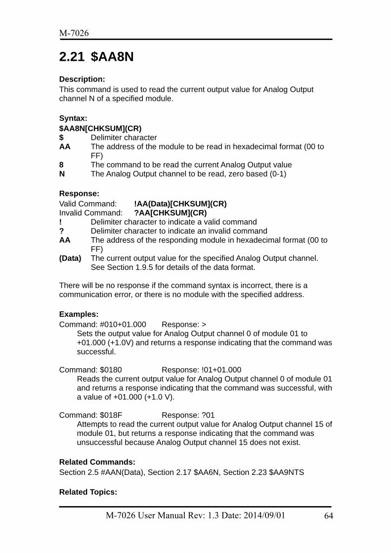
2.21 $AA8N Description: This command is used to read the current output value for Analog Output channel N of a specified module. Syntax: $AA8N[CHKSUM](CR) $ Delimiter character AA The address of the module to be read in hexadecimal format (00 to
FF) 8 The command to be read the current Analog Output value N The Analog Output channel to be read, zero based (0-1) Response: Valid Command: !AA(Data)[CHKSUM](CR) Invalid Command: ?AA[CHKSUM](CR) ! Delimiter character to indicate a valid command ? Delimiter character to indicate an invalid command AA The address of the responding module in hexadecimal format (00 to
FF) (Data) The current output value for the specified Analog Output channel.
See Section 1.9.5 for details of the data format. There will be no response if the command syntax is incorrect, there is a communication error, or there is no module with the specified address. Examples: Command: #010+01.000 Response: >
Sets the output value for Analog Output channel 0 of module 01 to +01.000 (+1.0V) and returns a response indicating that the command was successful.
Command: $0180 Response: !01+01.000
Reads the current output value for Analog Output channel 0 of module 01 and returns a response indicating that the command was successful, with a value of +01.000 (+1.0 V).
Command: $018F Response: ?01
Attempts to read the current output value for Analog Output channel 15 of module 01, but returns a response indicating that the command was unsuccessful because Analog Output channel 15 does not exist.
Related Commands: Section 2.5 #AAN(Data), Section 2.17 $AA6N, Section 2.23 $AA9NTS Related Topics:
M-7026 User Manual Rev: 1.3 Date: 2014/09/01 64
M-7026
Section 1.9.5 Analog Output Type Codes and Data Format
M-7026 User Manual Rev: 1.3 Date: 2014/09/01 65
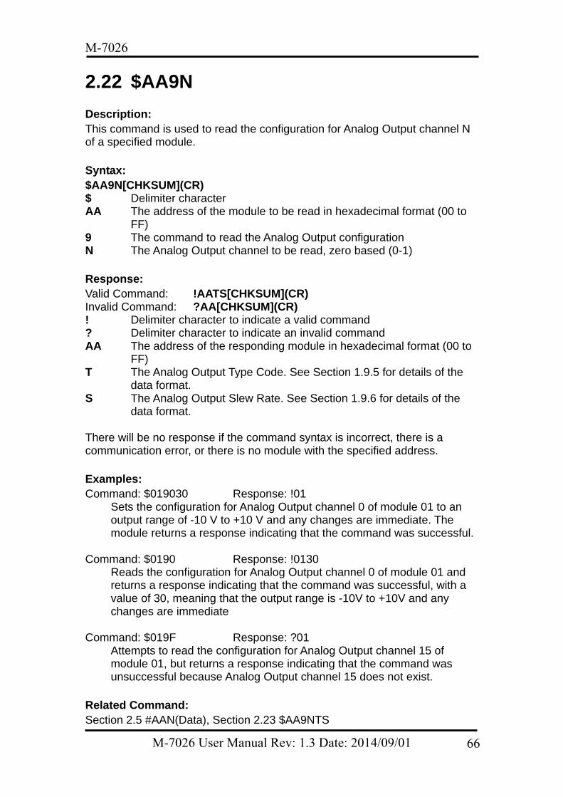
M-7026
2.22 $AA9N Description: This command is used to read the configuration for Analog Output channel N of a specified module. Syntax: $AA9N[CHKSUM](CR) $ Delimiter character AA The address of the module to be read in hexadecimal format (00 to
FF) 9 The command to read the Analog Output configuration N The Analog Output channel to be read, zero based (0-1) Response: Valid Command: !AATS[CHKSUM](CR) Invalid Command: ?AA[CHKSUM](CR) ! Delimiter character to indicate a valid command ? Delimiter character to indicate an invalid command AA The address of the responding module in hexadecimal format (00 to
FF) T The Analog Output Type Code. See Section 1.9.5 for details of the
data format. S The Analog Output Slew Rate. See Section 1.9.6 for details of the
data format. There will be no response if the command syntax is incorrect, there is a communication error, or there is no module with the specified address. Examples: Command: $019030 Response: !01
Sets the configuration for Analog Output channel 0 of module 01 to an output range of -10 V to +10 V and any changes are immediate. The module returns a response indicating that the command was successful.
Command: $0190 Response: !0130
Reads the configuration for Analog Output channel 0 of module 01 and returns a response indicating that the command was successful, with a value of 30, meaning that the output range is -10V to +10V and any changes are immediate
Command: $019F Response: ?01
Attempts to read the configuration for Analog Output channel 15 of module 01, but returns a response indicating that the command was unsuccessful because Analog Output channel 15 does not exist.
Related Command: Section 2.5 #AAN(Data), Section 2.23 $AA9NTS
M-7026 User Manual Rev: 1.3 Date: 2014/09/01 66

M-7026
Related Topics: Section 1.9.5 Analog Output Type Codes and Data Format Section 1.9.6 Analog Output Slew Rate Control
M-7026 User Manual Rev: 1.3 Date: 2014/09/01 67
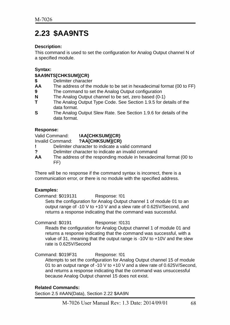
M-7026
2.23 $AA9NTS Description: This command is used to set the configuration for Analog Output channel N of a specified module. Syntax: $AA9NTS[CHKSUM](CR) $ Delimiter character AA The address of the module to be set in hexadecimal format (00 to FF) 9 The command to set the Analog Output configuration N The Analog Output channel to be set, zero based (0-1) T The Analog Output Type Code. See Section 1.9.5 for details of the
data format. S The Analog Output Slew Rate. See Section 1.9.6 for details of the
data format. Response: Valid Command: !AA[CHKSUM](CR) Invalid Command: ?AA[CHKSUM](CR) ! Delimiter character to indicate a valid command ? Delimiter character to indicate an invalid command AA The address of the responding module in hexadecimal format (00 to
FF) There will be no response if the command syntax is incorrect, there is a communication error, or there is no module with the specified address. Examples: Command: $019131 Response: !01
Sets the configuration for Analog Output channel 1 of module 01 to an output range of -10 V to +10 V and a slew rate of 0.625V/Second, and returns a response indicating that the command was successful.
Command: $0191 Response: !0131
Reads the configuration for Analog Output channel 1 of module 01 and returns a response indicating that the command was successful, with a value of 31, meaning that the output range is -10V to +10V and the slew rate is 0.625V/Second
Command: $019F31 Response: !01
Attempts to set the configuration for Analog Output channel 15 of module 01 to an output range of -10 V to +10 V and a slew rate of 0.625V/Second, and returns a response indicating that the command was unsuccessful because Analog Output channel 15 does not exist.
Related Commands: Section 2.5 #AAN(Data), Section 2.22 $AA9N
M-7026 User Manual Rev: 1.3 Date: 2014/09/01 68
M-7026
Related Topics: Section 1.9.5 Analog Output Type Codes and Data Format Section 1.9.6 Analog Output Slew Rate Control
M-7026 User Manual Rev: 1.3 Date: 2014/09/01 69
M-7026
2.24 $AAB Description: This command is used to detect whether any Analog Input channels of a specified module are under range. Syntax: $AAB[CHKSUM](CR) $ Delimiter character AA The address of the module to be read in hexadecimal format (00 to
FF) B The command to detect the Analog Input channels that are under
range Response: Valid Command: !AANN[CHKSUM](CR) Invalid Command: ?AA[CHKSUM](CR) ! Delimiter character to indicate a valid command ? Delimiter character to indicate an invalid command AA The address of the responding module in hexadecimal format (00 to
FF) NN A two-digit hexadecimal value representing the detection results for
all Analog Input channels (00 to 3F), where bit 0 corresponds to channel 0, bit 1 corresponds to channel 1, etc. If the bit is 0, it denotes that the channel is normal. If the bit is 1, it denotes that the channel is under range.
There will be no response if the command syntax is incorrect, there is a communication error, or there is no module with the specified address. Examples: Command: $017C0R07 Response: !01
Sets the Type Code for Analog Input channel 0 of module 01 to 07 (+4 to +20 mA) and the module returns a response indicating that the command was successful.
Command: $01B Response: !0101
Detects which Analog Input channels of module 01 are under range and returns a response indicating that the command was successful, with a value 01, meaning that Analog Input channel 0 is under range.
Note: This command is only applicable when either Type Code 0x07 (+4 to +20mA) or Type Code 0x1A (+0 to +20mA) is used. Related Commands: Section 2.3 #AA, Section 2.4 #AAN, Section 2.20 $AA8Ci, Section 2.18
M-7026 User Manual Rev: 1.3 Date: 2014/09/01 70
M-7026
$AA7CiRrr Related Topics: Section 1.9.2 Analog Input Type Code Settings Section 1.9.4 Analog Input Type Codes and Data Format
M-7026 User Manual Rev: 1.3 Date: 2014/09/01 71
M-7026
2.25 $AABO Description: This command is used to detect the status of the wire connections for each Analog Output channel of a specified module. Syntax: $AABO[CHKSUM](CR) $ Delimiter character AA The address of the module where the status of the wiring is to be
detected in hexadecimal format (00 to FF) BO The command to detect the status of the wiring for each Analog
Output channel Response: Valid Command: !AANN[CHKSUM](CR) Invalid Command: ?AA[CHKSUM](CR) ! Delimiter character to indicate a valid command ? Delimiter character to indicate an invalid command AA The address of the responding module in hexadecimal format (00 to
FF) NN A two-digit hexadecimal value representing the detection results for
the Analog Output channels (00 to 03), where bit 0 corresponds to channel 0, bit 1 corresponds to channel 1, etc. If the bit is 0, it denotes that the channel is either disabled or normal. If the bit is 1, it denotes that the channel is enabled and there is no wire connected.
There will be no response if the command syntax is incorrect, there is a communication error, or there is no module with the specified address. Examples: Command: $01BO Response: !0101
Detects the status of the wire connections for all Analog Outputs channels of module 01 and returns a response indicating that the command was successful, with a value of 01, meaning that no wire is connected to channel 1.
Note: This command is only applicable to Type Code 0 (+0 to +20 mA) and Type Code 1 (+4 to +20 mA). Related Commands: Section 2.22 $AA9N, Section 2.23 $AA9NTS Related Topics: Section 1.9.5 Analog Output Type Codes and Data Format
M-7026 User Manual Rev: 1.3 Date: 2014/09/01 72
M-7026
2.26 $AAC Description: This command is used to clear the Digital Input and Digital Output latch data for a specified module. Syntax: $AAC[CHKSUM](CR) $ Delimiter character AA The address of the module to be cleared in hexadecimal format (00 to
FF) C The command to clear the Digital Input and Digital Output latch data Response: Valid Command: !AA[CHKSUM](CR) Invalid Command: ?AA[CHKSUM](CR) ! Delimiter character to indicate a valid command ? Delimiter character to indicate an invalid command AA The address of the responding module in hexadecimal format (00 to
FF) There will be no response if the command syntax is incorrect, there is a communication error, or there is no module with the specified address. Examples: Command: $01L1 Response: !030100
Reads the low latch data for module 01 and returns a response indicating that the command was successful, with a value of 030100 showing that Digital Output channels 0 and 1 and Digital Input channel 0 are latched low.
Command: $01C Response: !01
Clears the latch data for all channels of module 01 and returns a response indicating that the command was successful.
Command: $01L1 Response: !000000
Reads the low latch data for module 01 and returns a response indicating that the command was successful, with a value of 000000 showing that all latched Digital Output and Digital Input channels have been cleared.
Related Commands: Section 2.31 $AALS
M-7026 User Manual Rev: 1.3 Date: 2014/09/01 73
M-7026
2.27 $AAE Description: This command is used to read whether the counter edge for each Digital Input channel of a specified module is rising or falling. Syntax: $AAE[CHKSUM](CR) $ Delimiter character AA The address of the module to be read in hexadecimal format (00 to
FF) E The command to read the status of the counter edge for the Digital
Input channels Response: Valid Command: !AAnn[CHKSUM](CR) Invalid Command: ?AA[CHKSUM](CR) ! Delimiter character to indicate a valid command ? Delimiter character to indicate an invalid command AA The address of the responding module in hexadecimal format (00 to
FF) nn A two-digit hexadecimal value representing the Digital Input channel,
where bit 0 corresponds to channel 0, and bit 1 corresponds to channel 1, etc. When the bit is 0, it denotes that the counter edge for the channel is falling, and 1 denotes that the counter edge for the channel is rising.
There will be no response if the command syntax is incorrect, there is a communication error, or there is no module with the specified address. Examples: Command: $01E3A Response: !01
Sets the counter edges for Digital Input channels 0, 1, 3, 4 and 5 of module 01 to rising, and the counter edges for all other Digital Input channels to falling. The module returns a response indicating that the command was successful.
Command: $01E Response: !013A
Reads the status of the counter edges for all Digital Input channels on module 01 and returns a response indicating that the command was successful, with a value of 3A, which denotes that the counters edges for Digital Input channels 0, 1, 3, 4 and 5 are rising and the counter edges for all other Digital Input channels are falling.
Related Commands: Section 2.28 $AAEnn
M-7026 User Manual Rev: 1.3 Date: 2014/09/01 74
M-7026
2.28 $AAEnn Description: This command is used to specify whether the counter edges for each Digital Input channel of a specified module are to be rising or falling. Syntax: $AAEnn[CHKSUM](CR) $ Delimiter character AA The address of the module to be set in hexadecimal format (00 to FF) E The command to set the counter edges for the Digital Input channels nn A two-digit hexadecimal value representing the Digital Input channel,
where bit 0 corresponds to channel 0, and bit 1 corresponds to channel 1, etc. When the bit is 0, it denotes that the counter edge for the channel will be set to falling, and 1 denotes that the counter edge for the channel will be set to rising.
Response: Valid Command: !AA[CHKSUM](CR) Invalid Command: ?AA[CHKSUM](CR) ! Delimiter character to indicate a valid command ? Delimiter character to indicate an invalid command AA The address of the responding module in hexadecimal format (00 to
FF) There will be no response if the command syntax is incorrect, there is a communication error, or there is no module with the specified address. Examples: Command: $01E3A Response: !01
Sets the counter edges for Digital Input channels 0, 1, 3, 4 and 5 of module 01 to rising, and the counter edges for all other Digital Input channels to falling. The module returns a response indicating that the command was successful.
Command: $01E Response: !013A
Reads the status of the counter edges for all Digital Input channels on module 01 and returns a response indicating that the command was successful, with a value of 3A, which denotes that the counter edges for Digital Input channels 0, 1, 3, 4 and 5 are rising and the counter edges for all other Digital Input channels are falling.
Related Commands: Section 2.27 $AAE
M-7026 User Manual Rev: 1.3 Date: 2014/09/01 75
M-7026
2.29 $AAF Description: This command is used to read the firmware version information for a specified module. Syntax: $AAF[CHKSUM](CR) $ Delimiter character AA The address of the module to be read in hexadecimal format (00 to
FF) F The command to read the firmware version information Response: Valid Command: !AA(Data)[CHKSUM](CR) Invalid Command: ?AA[CHKSUM](CR) ! Delimiter character to indicate a valid command ? Delimiter character to indicate an invalid command AA The address of the responding module in hexadecimal format (00 to
FF) (Data) The firmware version information for the module as a string value There will be no response if the command syntax is incorrect, there is a communication error, or there is no module with the specified address. Examples: Command: $01F Response: !01A2.0
Reads the firmware version information for module 01 and returns a response indicating that the command was successful and showing that the current firmware is version A1.0.
Related Commands: None
M-7026 User Manual Rev: 1.3 Date: 2014/09/01 76
M-7026
2.30 $AAI Description: This command is used to read the status of the INIT switch on a specified module. Syntax: $AAI[CHKSUM](CR) $ Delimiter character AA The address of the module to be read in hexadecimal format (00 to
FF) I The command to read the status of the INIT switch on the module Response: Valid Command: !AAS[CHKSUM](CR) Invalid Command: ?AA[CHKSUM](CR) ! Delimiter character to indicate a valid command ? Delimiter character to indicate an invalid command AA The address of the responding module in hexadecimal format (00 to
FF) S The status of the INIT switch on the module
0: The INIT switch is currently in the INIT position 1: The INIT switch is currently in the Normal position
There will be no response if the command syntax is incorrect, there is a communication error, or there is no module with the specified address. Examples: Command: $01I Response: !010
Reads the status of the INIT switch on module 01 and returns a response indicating that the command was successful and showing that the switch is currently in the INIT position.
Related Commands: None Related Topics: Section 5.1 INIT Mode
M-7026 User Manual Rev: 1.3 Date: 2014/09/01 77
M-7026
2.31 $AALS Description: This command is used to read the status of the latched Digital Input and Digital Output channels of a specified module. Syntax: $AALS[CHKSUM](CR) $ Delimiter character AA The address of the module to be read in hexadecimal format (00 to
FF) L The command to read the status of the latched Digital Input and
Digital Output channels S The status to be read
0: Reads the status of the low latched Digital Input and Digital Output channels
1: Reads the status of the high latched Digital Input and Digital Output channels
Response: Valid Command: !(Data)[CHKSUM](CR) Invalid Command: ?AA[CHKSUM](CR) ! Delimiter character to indicate a valid command ? Delimiter character to indicate an invalid command AA The address of the responding module in hexadecimal format (00 to
FF) (Data) The status of the latched Digital Output and Digital Input channels
represented by a four digit hexadecimal value followed by 00. There will be no response if the command syntax is incorrect, there is a communication error, or there is no module with the specified address. Examples: Command: $01L1 Response: !010200
Reads the status of the high latched Digital Output and Digital Input channels of module 01 and returns a response indicating that the command was successful, with a value of 010200 showing that Digital Output channel 0 and Digital Input channel 1 are latched high.
Command: $01C Response: !01
Clears the status of the latched Digital Output and Digital Input channels of module 01 and returns a response indicating that the command was successful.
Command: $01L1 Response: !000000
Reads the status of the high latched Digital Output and Digital Input channels of module 01 and returns a response indicating that the command was successful, with a value of 000000 showing that all high
M-7026 User Manual Rev: 1.3 Date: 2014/09/01 78
M-7026
latched Digital Output and Digital Input channels have been cleared. Command: $01L2 Response: ?01
Attempts to read the status of the high latched Digital Output and Digital Input channels of module 01, but returns a response indicating that the command was unsuccessful because the status byte parameter was incorrect.
Related Commands: Section 2.26 $AAC, Section 2.62 @AADODD
M-7026 User Manual Rev: 1.3 Date: 2014/09/01 79
M-7026
2.32 $AAM Description: This command is used to read the name of a specified module. Syntax: $AAM[CHKSUM](CR) $ Delimiter character AA The address of the module to be read in hexadecimal format (00 to
FF) M The command to read the name of the module Response: Valid Command: !AA(Data)[CHKSUM](CR) Invalid Command: ?AA[CHKSUM](CR) ! Delimiter character to indicate a valid command ? Delimiter character to indicate an invalid command AA The address of the responding module in hexadecimal format (00 to
FF) (Data) The name of the module as a string value There will be no response if the command syntax is incorrect, there is a communication error, or there is no module with the specified address. Examples: Command: ~01O7026 Response: !01
Sets the name of module 01 to “7026” and returns a response indicating that the command was successful.
Command: $01M Response: !017026
Reads the name of module 01 and returns a response indicating that the command was successful, and that the name is “7026”.
Related Commands: Section 2.49 ~AAO(Data)
M-7026 User Manual Rev: 1.3 Date: 2014/09/01 80
M-7026
2.33 $AAP Description: This command is used to read which communication protocol is supported and currently being used by a specified module. Syntax: $AAP[CHKSUM](CR) $ Delimiter character AA The address of the module to be read in hexadecimal format (00 to
FF) P The command to read the communication protocol Response: Valid Command: !AASC[CHKSUM](CR) Invalid Command: ?AA[CHKSUM](CR) ! Delimiter character to indicate a valid command ? Delimiter character to indicate an invalid command AA The address of the responding module in hexadecimal format (00 to
FF) S Indicates which protocol is supported
0: Only the DCON protocol is supported 1: Both the DCON and Modbus RTU protocols are supported
C Indicates which protocol is currently being used 0: The protocol set in the EEPROM is DCON 1: The protocol set in the EEPROM is Modbus RTU
There will be no response if the command syntax is incorrect, there is a communication error, or there is no module with the specified address. Examples: Command: $01P1 Response: !01
Sets the communication protocol for module 01 to Modbus RTU and returns a response indicating that the command was successful.
Command: $01P Response: !0111
Reads which communication protocol is being used by module 01 and returns a response indicating that the command was successful with a value of 11, meaning that the module supports both the DCON and Modbus RTU protocols, and that the protocol which will be used at the next power-on reset is Modbus RTU.
Related Commands: Section 2.34 $AAPN
M-7026 User Manual Rev: 1.3 Date: 2014/09/01 81
M-7026
2.34 $AAPN Description: This command is used to set the communication protocol to be used by a specified module. Syntax: $AAPN[CHKSUM](CR) $ Delimiter character AA The address of the module to be set in hexadecimal format (00 to FF) P The command to set the communication protocol N The protocol to be used
0: DCON 1: Modbus RTU
Note: Before using this command, the INIT switch must be in the INIT position, see Section 5.1 for details. The settings for the new protocol are saved in the EEPROM and will become effective after the next power-on reset. Response: Valid Command: !AA[CHKSUM](CR) Invalid Command: ?AA[CHKSUM](CR) ! Delimiter character to indicate a valid command ? Delimiter character to indicate an invalid command AA The address of the responding module in hexadecimal format (00 to
FF) There will be no response if the command syntax is incorrect, there is a communication error, or there is no module with the specified address. Examples: Command: $01P1 Response: ?01
Attempts to set the communication protocol for module 01 to Modbus RTU, but returns a response indicating that the command was unsuccessful, because the INIT switch is not in INIT position.
Command: $01P1 Response: !01
Sets the communication protocol for module 01 to Modbus RTU and returns a response indicating that the command was successful. The new protocol will become effective after the next power-on reset.
Command: $01P Response: !0111
Reads which communication protocol is being used by module 01 and returns a response indicating that the command was successful, with a value of 11 meaning that the module supports both the DCON and Modbus RTU protocols, and that the protocol which will be used at the next power-on reset is Modbus RTU.
M-7026 User Manual Rev: 1.3 Date: 2014/09/01 82
M-7026
Related Commands: Section 2.33 $AAP Related Topics: Section 5.1 INIT Mode
M-7026 User Manual Rev: 1.3 Date: 2014/09/01 83
M-7026
2.35 $AAS1 Description: This command is used to reload the factory default calibration parameters for a specified module, including the internal calibration parameters. Syntax: $AAS1[CHKSUM](CR) $ Delimiter character AA The address of the module where the default calibration parameters
are to be reloaded in hexadecimal format (00 to FF) S1 The command to reload the factory default calibration parameters Response: Valid Command: !AA[CHKSUM](CR) Invalid Command: ?AA[CHKSUM](CR) ! Delimiter character to indicate a valid command ? Delimiter character to indicate an invalid command AA The address of the responding module in hexadecimal format (00 to
FF) There will be no response if the command syntax is incorrect, there is a communication error, or there is no module with the specified address. Note: If the accuracy of either the Analog Input or the Analog Output is not within the specifications, the factory default calibration parameters must be reloaded. After sending the $AAS1 command, the parameters will be changed directly without needing to reboot the module. Examples: Command: $01S1 Response: !01
Sends a command to reload the factory default calibration parameters for module 01 and returns a response indicating that the command was successful.
Command: $01S0 Response: ?01
Attempts to send a command to reload the factory default calibration parameters for module 01, but returns a response indicating that the command was unsuccessful because the command was incorrect.
Related Commands: Section 2.6 $AA0, Section 2.7 $AA0N, Section 2.8 $AA1, Section 2.9 $AA1N, Section 2.11 $AA3NVV, Section 2.47 ~AAEV Related Topics: Section 1.8 Calibration
M-7026 User Manual Rev: 1.3 Date: 2014/09/01 84
M-7026
2.36 ~** Description: This command is used to inform all modules on the network that the host is OK. Syntax: ~**[CHKSUM](CR) ~ Delimiter character ** The “Host OK” command Response: There is no response to this command. Examples: Command: ~** No response
Sends a “Host OK” command to all modules on the network. Related Commands: Section 2.37 ~AA0, Section 2.38 ~AA1, Section 2.39 ~AA2, Section 2.40 ~AA3ETT Related Topics: Section 5.2 Dual Watchdog Operation
M-7026 User Manual Rev: 1.3 Date: 2014/09/01 85
M-7026
2.37 ~AA0 Description: This command is used to read the status of the Host Watchdog for a specified module. Syntax: ~AA0[CHKSUM](CR) ~ Delimiter character AA The address of the module to be read in hexadecimal format (00 to
FF) 0 The command to read the status of the Host Watchdog Response: Valid Command: !AASS[CHKSUM](CR) Invalid Command: ?AA[CHKSUM](CR) ! Delimiter character to indicate a valid command ? Delimiter character to indicate an invalid command AA The address of the responding module in hexadecimal format (00 to
FF) SS A two-digit hexadecimal value that represents the status of the Host
Watchdog, where: Bit 2: 0 indicates that no Host Watchdog timeout has occurred, and 1
indicates that a Host Watchdog timeout has occurred. Bit 7: 0 indicates that the Host Watchdog is disabled, and 1 indicates
that the Host Watchdog is enabled. There will be no response if the command syntax is incorrect, there is a communication error, or there is no module with the specified address. Note: The status information for the Host Watchdog is stored in the EEPROM and can only be reset using the ~AA1 command. See Section 2.38 for details.
Examples: Command: ~010 Response: !0100
Reads the status of the Host Watchdog for module 01 and returns a response indicating that the command was successful, with a value of 00, meaning that the Host Watchdog is disabled and no Host Watchdog timeout has occurred.
Command: ~020 Response: !0204
Reads the status of the Host Watchdog for module 02 and returns a response indicating that the command was successful, with a value of 04, meaning that a Host Watchdog timeout has occurred.
Related Commands:
M-7026 User Manual Rev: 1.3 Date: 2014/09/01 86
M-7026
Section 2.36 ~**, Section 2.38 ~AA1, Section 2.39 ~AA2, Section 2.40 ~AA3ETT Related Topics: Section 5.2 Dual Watchdog Operation
M-7026 User Manual Rev: 1.3 Date: 2014/09/01 87
M-7026
2.38 ~AA1 Description: This command is used to reset the status of the Host Watchdog timeout for a specified module. Syntax: ~AA1[CHKSUM](CR) ~ Delimiter character AA The address of the module to be reset in hexadecimal format (00 to
FF) 1 The command to reset the status of the Host Watchdog timeout Response: Valid Command: !AA[CHKSUM](CR) Invalid Command: ?AA[CHKSUM](CR) ! Delimiter character to indicate a valid command ? Delimiter character to indicate an invalid command AA The address of the responding module in hexadecimal format (00 to
FF) There will be no response if the command syntax is incorrect, there is a communication error, or there is no module with the specified address. Examples: Command: ~010 Response: !0104
Reads the status of the Host Watchdog for module 01 and returns a response indicating that the command was successful, and that a Host Watchdog timeout has occurred.
Command: ~011 Response: !01
Resets the status of the Host Watchdog timeout for module 01 and returns a response indicating that the command was successful.
Command: ~010 Response: !0100
Reads the status of the Host Watchdog for module 01 and returns a response indicating that the command was successful, and showing that no Host Watchdog timeout has occurred.
Related Commands: Section 2.36 ~**, Section 2.37 ~AA0, Section 2.39 ~AA2, Section 2.40 ~AA3ETT Related Topics: Section 5.2 Dual Watchdog Operation
M-7026 User Manual Rev: 1.3 Date: 2014/09/01 88
M-7026
2.39 ~AA2 Description: This command is used to read the Host Watchdog timeout value for a specified module. Syntax: ~AA2[CHKSUM](CR) ~ Delimiter character AA The address of the module to be read in hexadecimal format (00 to
FF) 2 The command to read the Host Watchdog timeout value Response: Valid Command: !AAEVV[CHKSUM](CR) Invalid Command: ?AA[CHKSUM](CR) ! Delimiter character to indicate a valid command ? Delimiter character to indicate an invalid command AA The address of the responding module in hexadecimal format (00 to
FF) E The status of the Host Watchdog
0: The Host Watchdog is disabled 1: The Host Watchdog is enabled
VV A two-digit hexadecimal value that represents the timeout value in tenths of a second. For example, 01 denotes 0.1 seconds and FF denotes 25.5 seconds.
There will be no response if the command syntax is incorrect, there is a communication error, or there is no module with the specified address. Examples: Command: ~013164 Response: !01
Enables the Host Watchdog for module 01 and sets the Host Watchdog timeout value to 64 (10.0 seconds). The module returns a response indicating that the command was successful.
Command: ~012 Response: !01164
Reads the Host Watchdog timeout value for module 01 and returns a response indicating that the command was successful, with a value of 1FF, which denotes that the Host Watchdog is enabled and that the Host Watchdog timeout value is 10.0 seconds (64).
Related Commands: Section 2.36 ~**, Section 2.37 ~AA0, Section 2.38 ~AA1, Section 2.40 ~AA3ETT Related Topics:
M-7026 User Manual Rev: 1.3 Date: 2014/09/01 89
M-7026
Section 5.2 Dual Watchdog Operation
M-7026 User Manual Rev: 1.3 Date: 2014/09/01 90
M-7026
2.40 ~AA3ETT Description: This command is used to enable or disable the Host Watchdog for a specified module and sets the Host Watchdog timeout value. Syntax:
~AA3ETT[CHKSUM](CR) ~ Delimiter character AA The address of the module to be set in hexadecimal format (00 to FF) 3 The command to set the Host Watchdog E The command to set the Host Watchdog
0: Disables the Host Watchdog 1: Enables the Host Watchdog
TT A two-digit hexadecimal value to represent the Host Watchdog timeout value in tenths of a second. For example, 01 denotes 0.1 seconds and FF denotes 25.5 seconds.
Response: Valid Command: !AA[CHKSUM](CR) Invalid Command: ?AA[CHKSUM](CR) ! Delimiter character to indicate a valid command ? Delimiter character to indicate an invalid command AA The address of the responding module in hexadecimal format (00 to
FF) There will be no response if the command syntax is incorrect, there is a communication error, or there is no module with the specified address. Examples: Command: ~013164 Response: !01
Enables the Host Watchdog for module 01 and sets the Host Watchdog timeout value to 64 (10.0 seconds). The module returns a response indicating that the command was successful.
Command: ~012 Response: !01164
Reads the Host Watchdog timeout value for module 01 and returns a response indicating that the command was successful, with a value of 164, which denotes that the Host Watchdog is enabled and that the Host Watchdog timeout value is 10.0 seconds (64).
Related Commands: Section 2.36 ~**, Section 2.37 ~AA0, Section 2.38 ~AA1, Section 2.39 ~AA2 Related Topics: Section 5.2 Dual Watchdog Operation
M-7026 User Manual Rev: 1.3 Date: 2014/09/01 91
M-7026
Note: When a Host Watchdog timeout occurs, the Host Watchdog will be disabled. In this case the ~AA3ETT command should be sent again to re-enable the Host Watchdog.
M-7026 User Manual Rev: 1.3 Date: 2014/09/01 92
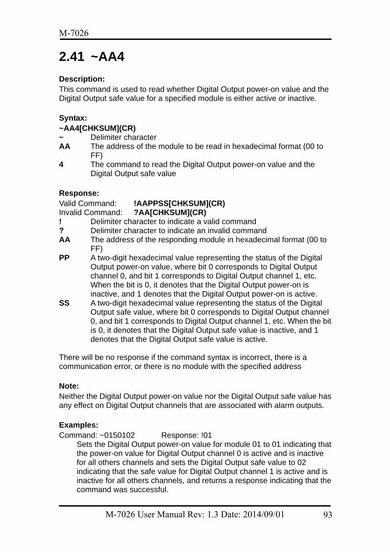
M-7026
2.41 ~AA4 Description: This command is used to read whether Digital Output power-on value and the Digital Output safe value for a specified module is either active or inactive. Syntax: ~AA4[CHKSUM](CR) ~ Delimiter character AA The address of the module to be read in hexadecimal format (00 to
FF) 4 The command to read the Digital Output power-on value and the
Digital Output safe value Response: Valid Command: !AAPPSS[CHKSUM](CR) Invalid Command: ?AA[CHKSUM](CR) ! Delimiter character to indicate a valid command ? Delimiter character to indicate an invalid command AA The address of the responding module in hexadecimal format (00 to
FF) PP A two-digit hexadecimal value representing the status of the Digital
Output power-on value, where bit 0 corresponds to Digital Output channel 0, and bit 1 corresponds to Digital Output channel 1, etc. When the bit is 0, it denotes that the Digital Output power-on is inactive, and 1 denotes that the Digital Output power-on is active.
SS A two-digit hexadecimal value representing the status of the Digital Output safe value, where bit 0 corresponds to Digital Output channel 0, and bit 1 corresponds to Digital Output channel 1, etc. When the bit is 0, it denotes that the Digital Output safe value is inactive, and 1 denotes that the Digital Output safe value is active.
There will be no response if the command syntax is incorrect, there is a communication error, or there is no module with the specified address Note: Neither the Digital Output power-on value nor the Digital Output safe value has any effect on Digital Output channels that are associated with alarm outputs. Examples: Command: ~0150102 Response: !01
Sets the Digital Output power-on value for module 01 to 01 indicating that the power-on value for Digital Output channel 0 is active and is inactive for all others channels and sets the Digital Output safe value to 02 indicating that the safe value for Digital Output channel 1 is active and is inactive for all others channels, and returns a response indicating that the command was successful.
M-7026 User Manual Rev: 1.3 Date: 2014/09/01 93
M-7026
Command: ~014 Response: !010102 Reads the Digital Output power-on value and the Digital Output safe value for module 01 and returns a response indicating that the command was successful, with a value of 0102, which denotes that the power-on value for Digital Output channel 0 is active and is inactive for all other channels, and that the safe value for Digital Output channel 1 is active and is inactive for all other channels.
Related Commands: Section 2.44 ~AA5PPSS
M-7026 User Manual Rev: 1.3 Date: 2014/09/01 94
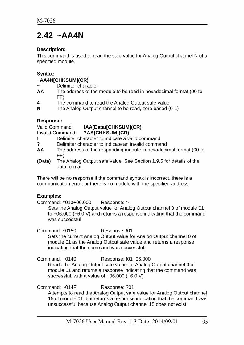
M-7026
2.42 ~AA4N Description: This command is used to read the safe value for Analog Output channel N of a specified module. Syntax: ~AA4N[CHKSUM](CR) ~ Delimiter character AA The address of the module to be read in hexadecimal format (00 to
FF) 4 The command to read the Analog Output safe value N The Analog Output channel to be read, zero based (0-1) Response: Valid Command: !AA(Data)[CHKSUM](CR) Invalid Command: ?AA[CHKSUM](CR) ! Delimiter character to indicate a valid command ? Delimiter character to indicate an invalid command AA The address of the responding module in hexadecimal format (00 to
FF) (Data) The Analog Output safe value. See Section 1.9.5 for details of the
data format. There will be no response if the command syntax is incorrect, there is a communication error, or there is no module with the specified address. Examples: Command: #010+06.000 Response: >
Sets the Analog Output value for Analog Output channel 0 of module 01 to +06.000 (+6.0 V) and returns a response indicating that the command was successful
Command: ~0150 Response: !01
Sets the current Analog Output value for Analog Output channel 0 of module 01 as the Analog Output safe value and returns a response indicating that the command was successful.
Command: ~0140 Response: !01+06.000
Reads the Analog Output safe value for Analog Output channel 0 of module 01 and returns a response indicating that the command was successful, with a value of +06.000 (+6.0 V).
Command: ~014F Response: ?01
Attempts to read the Analog Output safe value for Analog Output channel 15 of module 01, but returns a response indicating that the command was unsuccessful because Analog Output channel 15 does not exist.
M-7026 User Manual Rev: 1.3 Date: 2014/09/01 95

M-7026
Related Commands: Section 2.5 #AAN(Data), Section 2.43 ~AA5N Related Topics: Section 1.9.5 Analog Output Type Codes and Data Format
M-7026 User Manual Rev: 1.3 Date: 2014/09/01 96
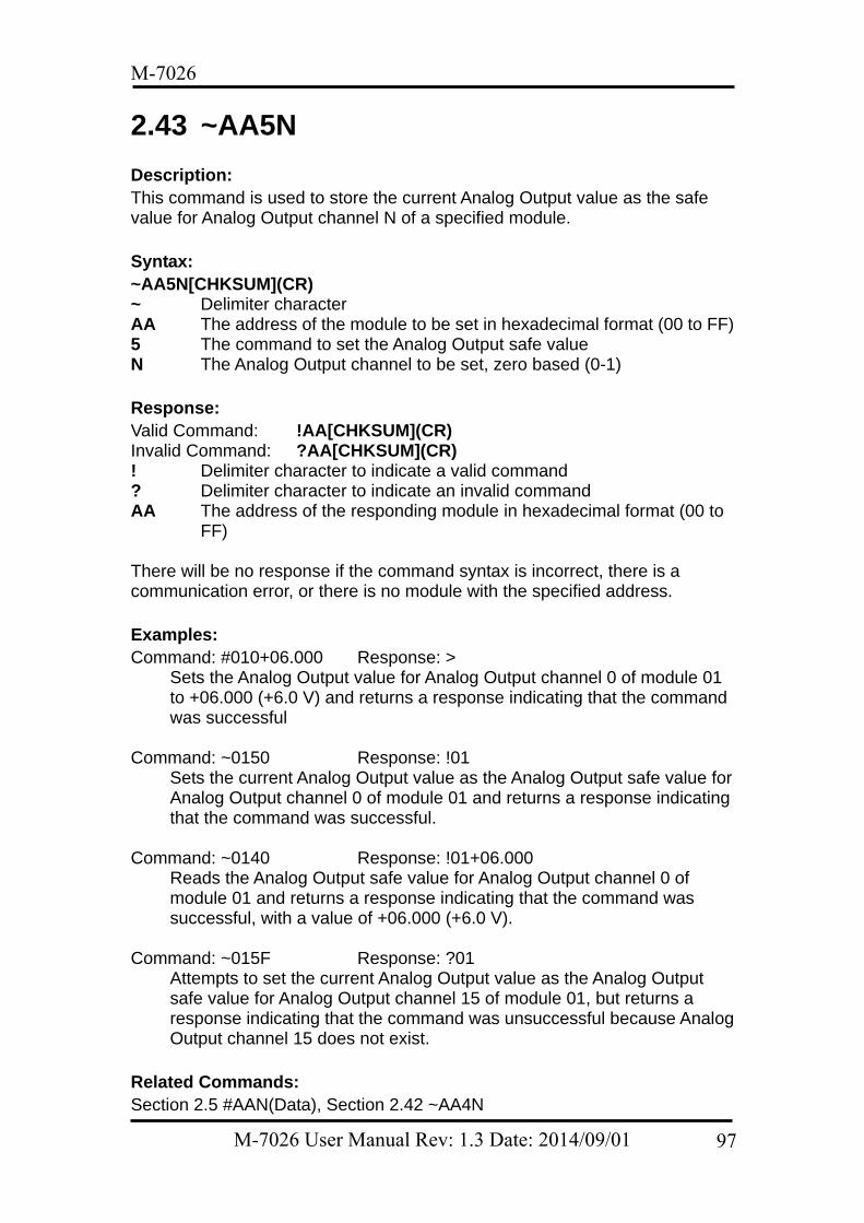
M-7026
2.43 ~AA5N Description: This command is used to store the current Analog Output value as the safe value for Analog Output channel N of a specified module. Syntax: ~AA5N[CHKSUM](CR) ~ Delimiter character AA The address of the module to be set in hexadecimal format (00 to FF) 5 The command to set the Analog Output safe value N The Analog Output channel to be set, zero based (0-1) Response: Valid Command: !AA[CHKSUM](CR) Invalid Command: ?AA[CHKSUM](CR) ! Delimiter character to indicate a valid command ? Delimiter character to indicate an invalid command AA The address of the responding module in hexadecimal format (00 to
FF) There will be no response if the command syntax is incorrect, there is a communication error, or there is no module with the specified address. Examples: Command: #010+06.000 Response: >
Sets the Analog Output value for Analog Output channel 0 of module 01 to +06.000 (+6.0 V) and returns a response indicating that the command was successful
Command: ~0150 Response: !01
Sets the current Analog Output value as the Analog Output safe value for Analog Output channel 0 of module 01 and returns a response indicating that the command was successful.
Command: ~0140 Response: !01+06.000
Reads the Analog Output safe value for Analog Output channel 0 of module 01 and returns a response indicating that the command was successful, with a value of +06.000 (+6.0 V).
Command: ~015F Response: ?01
Attempts to set the current Analog Output value as the Analog Output safe value for Analog Output channel 15 of module 01, but returns a response indicating that the command was unsuccessful because Analog Output channel 15 does not exist.
Related Commands: Section 2.5 #AAN(Data), Section 2.42 ~AA4N
M-7026 User Manual Rev: 1.3 Date: 2014/09/01 97

M-7026
Related Topics: Section 1.9.5 Analog Output Type Codes and Data Format
M-7026 User Manual Rev: 1.3 Date: 2014/09/01 98
M-7026
2.44 ~AA5PPSS Description: This command is used to set the Digital Output power-on value and the Digital Output safe value for a specified module to either active or inactive. Syntax: ~AA5PPSS[CHKSUM](CR) ~ Delimiter character AA The address of the module to be set in hexadecimal format (00 to FF) 5 The command to set the Digital Output power-on value and the Digital
Output safe value PP A two-digit hexadecimal value representing the status of the Digital
Output power-on value, where bit 0 corresponds to Digital Output channel 0, and bit 1 corresponds to Digital Output channel 1, etc. When the bit is 0, it denotes that the Digital Output power-on is inactive, and 1 denotes that the Digital Output power-on is active.
SS A two-digit hexadecimal value representing the status of the Digital Output safe value, where bit 0 corresponds to Digital Output channel 0, and bit 1 corresponds to Digital Output channel 1, etc. When the bit is 0, it denotes that the Digital Output safe value is inactive, and 1 denotes that the Digital Output safe value is active.
Response: Valid Command: !AA[CHKSUM](CR) Invalid Command: ?AA[CHKSUM](CR) ! Delimiter character to indicate a valid command ? Delimiter character to indicate an invalid command AA The address of the responding module in hexadecimal format (00 to
FF) There will be no response if the command syntax is incorrect, there is a communication error, or there is no module with the specified address. Note: Neither the Digital Output power-on value nor the Digital Output safe value has any effect on Digital Output channels that are associated with alarm outputs. Examples: Command: ~0150102 Response: !01
Sets the Digital Output power-on value for module 01 to 01 indicating that the power-on value for Digital Output channel 0 is active and is inactive for all others channels, and sets the Digital Output safe value to 02 indicating that the safe value for Digital Output channel 1 is active and is inactive for all others channels, and returns a response indicating that the command was successful.
Command: ~014 Response: !010102
M-7026 User Manual Rev: 1.3 Date: 2014/09/01 99

M-7026
Reads the Digital Output power-on value and the Digital Output safe value for module 01 and returns a response indicating that the command was successful, with a value of 0102, which denotes that the power-on value for Digital Output channel 0 is active and is inactive for all other channels, and that the safe value for Digital Output channel 1 is active and is inactive for all other channels.
Related Commands: Section 2.41 ~AA4
M-7026 User Manual Rev: 1.3 Date: 2014/09/01 100
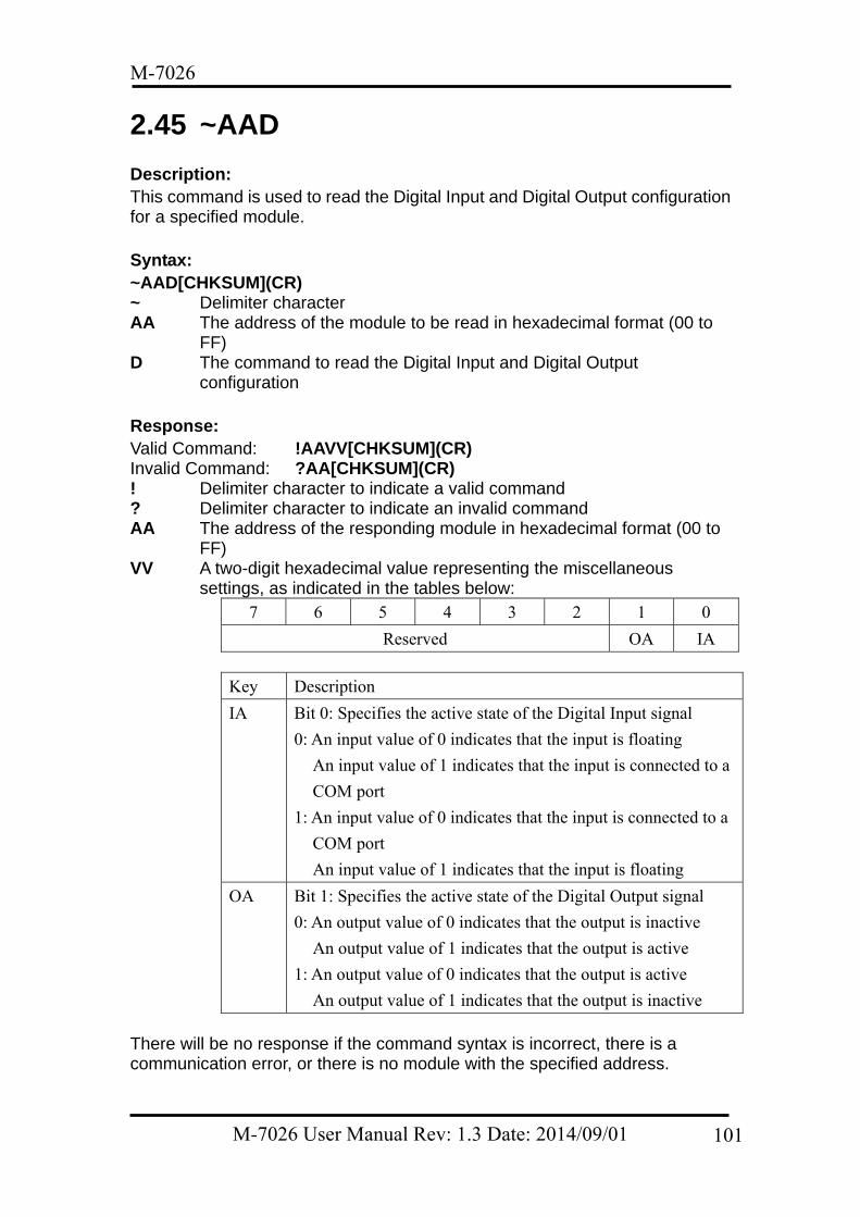
M-7026
2.45 ~AAD Description: This command is used to read the Digital Input and Digital Output configuration for a specified module. Syntax: ~AAD[CHKSUM](CR) ~ Delimiter character AA The address of the module to be read in hexadecimal format (00 to
FF) D The command to read the Digital Input and Digital Output
configuration Response: Valid Command: !AAVV[CHKSUM](CR) Invalid Command: ?AA[CHKSUM](CR) ! Delimiter character to indicate a valid command ? Delimiter character to indicate an invalid command AA The address of the responding module in hexadecimal format (00 to
FF) VV A two-digit hexadecimal value representing the miscellaneous
settings, as indicated in the tables below: 7 6 5 4 3 2 1 0
Reserved OA IA
Key Description
IA Bit 0: Specifies the active state of the Digital Input signal
0: An input value of 0 indicates that the input is floating
An input value of 1 indicates that the input is connected to a
COM port
1: An input value of 0 indicates that the input is connected to a
COM port
An input value of 1 indicates that the input is floating
OA Bit 1: Specifies the active state of the Digital Output signal
0: An output value of 0 indicates that the output is inactive
An output value of 1 indicates that the output is active
1: An output value of 0 indicates that the output is active
An output value of 1 indicates that the output is inactive There will be no response if the command syntax is incorrect, there is a communication error, or there is no module with the specified address.
M-7026 User Manual Rev: 1.3 Date: 2014/09/01 101
M-7026
Examples: Command: ~$01D01 Response: !01
Sets the miscellaneous settings for module 01 to 01, meaning that the Digital Output channels are in inactive mode, and returns a response indicating that the command was successful.
Command: ~$01D Response: !0101
Reads the miscellaneous settings for module 01 and returns a response indicating that the command was successful, with a value of 01, which denotes that the Digital Output channels are in inactive mode.
Related Commands: Section 2.46 ~AADVV, Section 2.61 @AADI, Section 2.62 @AADODD
M-7026 User Manual Rev: 1.3 Date: 2014/09/01 102
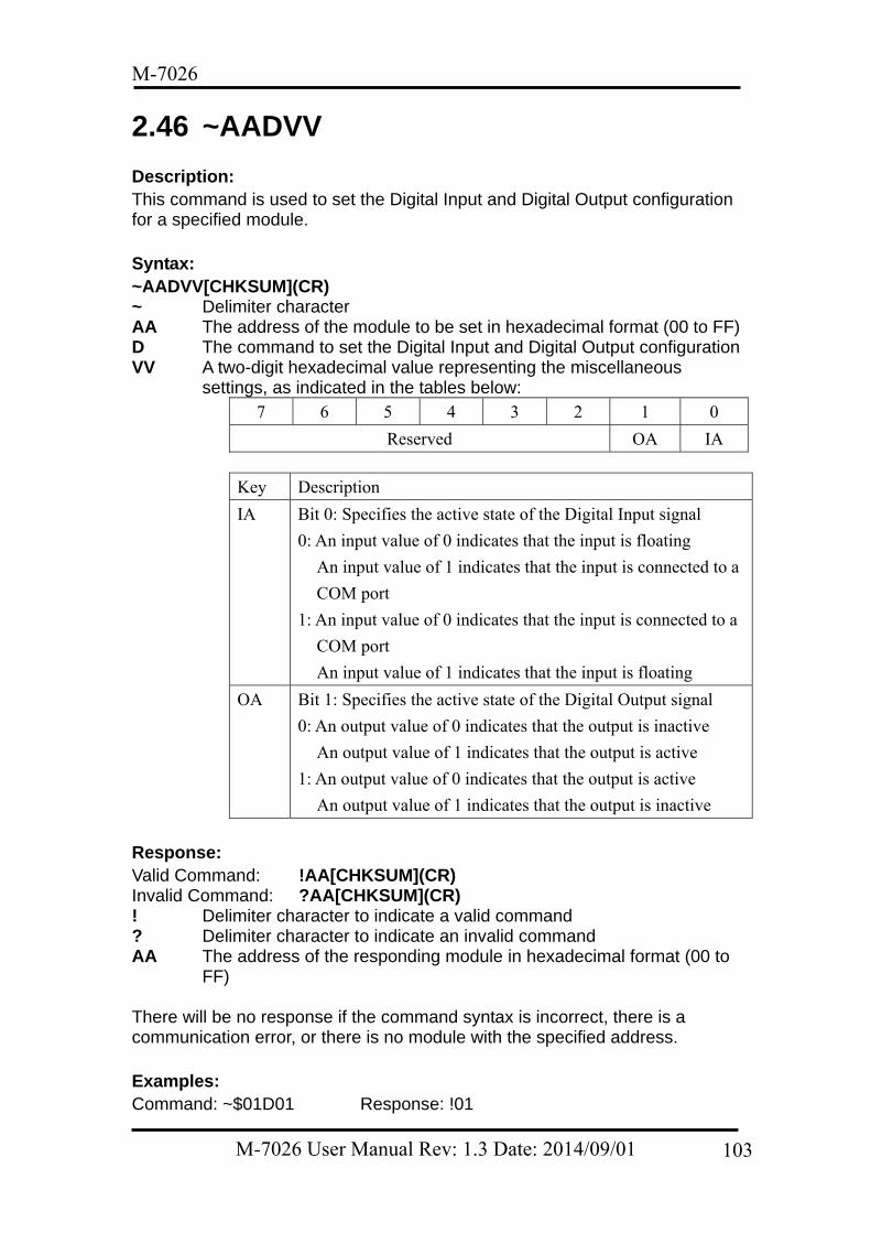
M-7026
2.46 ~AADVV Description: This command is used to set the Digital Input and Digital Output configuration for a specified module. Syntax: ~AADVV[CHKSUM](CR) ~ Delimiter character AA The address of the module to be set in hexadecimal format (00 to FF) D The command to set the Digital Input and Digital Output configuration VV A two-digit hexadecimal value representing the miscellaneous
settings, as indicated in the tables below: 7 6 5 4 3 2 1 0
Reserved OA IA
Key Description
IA Bit 0: Specifies the active state of the Digital Input signal
0: An input value of 0 indicates that the input is floating
An input value of 1 indicates that the input is connected to a
COM port
1: An input value of 0 indicates that the input is connected to a
COM port
An input value of 1 indicates that the input is floating
OA Bit 1: Specifies the active state of the Digital Output signal
0: An output value of 0 indicates that the output is inactive
An output value of 1 indicates that the output is active
1: An output value of 0 indicates that the output is active
An output value of 1 indicates that the output is inactive Response: Valid Command: !AA[CHKSUM](CR) Invalid Command: ?AA[CHKSUM](CR) ! Delimiter character to indicate a valid command ? Delimiter character to indicate an invalid command AA The address of the responding module in hexadecimal format (00 to
FF) There will be no response if the command syntax is incorrect, there is a communication error, or there is no module with the specified address. Examples: Command: ~$01D01 Response: !01
M-7026 User Manual Rev: 1.3 Date: 2014/09/01 103
M-7026
Sets the miscellaneous settings for module 01 to 01, meaning that the Digital Output channels are in inactive mode, and returns a response indicating that the command was successful.
Command: ~$01D Response: !0101
Reads the miscellaneous settings for module 01 and returns a response indicating that the command was successful, with a value of 01, which denotes that the Digital Output channels are in inactive mode.
Related Commands: Section 2.45 ~AAD, Section 2.61 @AADI, Section 2.62 @AADODD
M-7026 User Manual Rev: 1.3 Date: 2014/09/01 104
M-7026
2.47 ~AAEV Description: This command is used to enable or disable calibration for a specified module. Syntax: ~AAEV[CHKSUM](CR) ~ Delimiter character AA The address of the module where calibration is to be enabled or
disabled in hexadecimal format (00 to FF) E The command to set the calibration V The command to enable or disable calibration
0: Disables calibration 1: Enables calibration
Response: Valid Command: !AA[CHKSUM](CR) Invalid Command: ?AA[CHKSUM](CR) ! Delimiter character to indicate a valid command ? Delimiter character to indicate an invalid command AA The address of the responding module in hexadecimal format (00 to
FF) There will be no response if the command syntax is incorrect, there is a communication error, or there is no module with the specified address. Note: This command must be sent before any other calibration command can be used. Examples: Command: $010 Response: ?01
Attempts to send the command to perform a span calibration on module 01, but returns a response indicating that the command was unsuccessful because the “Enable Calibration” command (~AAEV) has not yet been sent.
Command: ~01E1 Response: !01
Enables calibration on module 01 and returns a response indicating that the command was successful.
Command: $010 Response: !01
Sends the command to perform a span calibration on module 01 and returns a response indicating that the command was successful.
Related Commands: Section 2.6 $AA0, Section 2.7 $AA0N, Section 2.8 $AA1, Section 2.9 $AA1N,
M-7026 User Manual Rev: 1.3 Date: 2014/09/01 105
M-7026
Section 2.35 $AAS1 Related Topics: Section 1.8 Calibration
M-7026 User Manual Rev: 1.3 Date: 2014/09/01 106
M-7026
2.48 ~AAI Description: This command is used to enable modification of the Baud Rate and checksum settings for a specified module using the software INIT function only. Syntax: ~AAI[CHKSUM](CR) ~ Delimiter character AA The address of the module to be set in hexadecimal format (00 to FF) I The command to enable the software INIT function Response: Valid Command: !AA[CHKSUM](CR) Invalid Command: ?AA[CHKSUM](CR) ! Delimiter character to indicate a valid command ? Delimiter character to indicate an invalid command AA The address of the responding module in hexadecimal format (00 to
FF) There will be no response if the command syntax is incorrect, there is a communication error, or there is no module with the specified address. Examples: Command: ~01T10 Response: !01
Sets the timeout value for the software INIT function on module 01 to 10 (16 seconds) and returns a response indicating that the command was successful.
Command: ~01I Response: !01
Enables the software INIT function on module 01 and returns a response indicating that the command was successful.
Command: %0101000600 Response: !01
Sets the Baud Rate for module 01 to 9600 bps and returns a response indicating that the command was successful.
Related Commands: Section 2.1 %AANNTTCCFF, Section 2.48 ~AAI, Section 2.52 ~AATnn Related Topics: Section 1.9 Configuration Section 5.1 INIT Mode
M-7026 User Manual Rev: 1.3 Date: 2014/09/01 107
M-7026
2.49 ~AAO(Data) Description: This command is used to set the name of a specified module Syntax: ~AAO(Data)[CHKSUM](CR) ~ Delimiter character AA The address of the module to be set in hexadecimal format (00 to FF) O The command to set the name of the module (Data) The new name of the module (Max. 12 characters) Response: Valid Command: !AA[CHKSUM](CR) Invalid Command: ?AA[CHKSUM](CR) ! Delimiter character to indicate a valid command ? Delimiter character to indicate an invalid command AA The address of the responding module in hexadecimal format (00 to
FF) There will be no response if the command syntax is incorrect, there is a communication error, or there is no module with the specified address. Examples: Command: ~01O7026 Response: !01
Sets the name of module 01 to “7026” and returns a response indicating that the command was successful.
Command: $01M Response: !017026
Reads the name of module 01 and returns a response indicating that the command was successful, with the name “7026”.
Command: ~01O123456789ABCDEF Response: ?01
Attempts to set the name of module 01 to “123456789ABCDEF”, but returns a response indicating that the command was unsuccessful, because the name is longer than 12 characters.
Related Commands: Section 2.32 $AAM
M-7026 User Manual Rev: 1.3 Date: 2014/09/01 108
M-7026
2.50 ~AARD Description: This command is used to read the response delay time for a specified module. Syntax: ~AARD[CHKSUM](CR) ~ Delimiter character AA The address of the module to be read in hexadecimal format (00 to
FF) RD The command to read the response delay time Response: Valid Command: !AATT[CHKSUM](CR) Invalid Command: ?AA[CHKSUM](CR) ! Delimiter character to indicate a valid command ? Delimiter character to indicate an invalid command AA The address of the responding module in hexadecimal format (00 to
FF) TT A two-digit hexadecimal value representing the response delay time
value in milliseconds. For example, 01 denotes 1 millisecond and 1A denotes 26 milliseconds. The value must be less than or equal to 1E.
There will be no response if the command syntax is incorrect, there is a communication error, or there is no module with the specified address. Examples: Command: ~01RD10 Response: !01
Sets the response delay time for module 01 to 10 (16 milliseconds) and returns a response indicating that the command was successful.
Command: ~01RD Response: !0110
Reads the response delay time for module 01 and returns a response indicating that the command was successful, with a value of 10 indicating 16 milliseconds, meaning that all responses will be sent after 16 milliseconds have elapsed.
Related Commands: Section 2.51 ~AARDTT
M-7026 User Manual Rev: 1.3 Date: 2014/09/01 109
M-7026
2.51 ~AARDTT Description: This command is used to set the response delay time for a specified module. Syntax: ~AARDTT[CHKSUM](CR) ~ Delimiter character AA The address of the module to be set in hexadecimal format (00 to FF) RD The command to set the response delay time TT A two-digit hexadecimal value representing the response time value
in milliseconds. For example, 01 denotes 1 millisecond and 1A denotes 26 milliseconds. The value must be less than or equal to 1E.
Response: Valid Command: !AA[CHKSUM](CR) Invalid Command: ?AA[CHKSUM](CR) ! Delimiter character to indicate a valid command ? Delimiter character to indicate an invalid command AA The address of the responding module in hexadecimal format (00 to
FF) There will be no response if the command syntax is incorrect, there is a communication error, or there is no module with the specified address. Examples: Command: ~01RD10 Response: !01
Sets the response delay time for module 01 to 10 (16 milliseconds) and returns a response indicating that the command was successful.
Command: ~01RD Response: !0110
Reads the response delay time for module 01 and returns a response indicating that the command was successful, with a value of 10 indicating 16 milliseconds, meaning that all responses will be sent after 16 milliseconds have elapsed.
Command: ~01RD1F Response: ?01
Attempts to set the response delay time for module 01 to 1F (31 milliseconds), but returns a response indicating that the command was unsuccessful because the duration was not within the valid range.
Related Commands: Section 2.50 ~AARD
M-7026 User Manual Rev: 1.3 Date: 2014/09/01 110
M-7026
2.52 ~AATnn Description: This command is used to set the timeout value for the software INIT function on a specified module. Syntax: ~AATnn[CHKSUM](CR) ~ Delimiter character AA The address of the module to be set in hexadecimal format (00 to FF) T The command to set the timeout value for the software INIT function nn A two-digit hexadecimal value representing the timeout value for the
software INIT function in seconds. For example, 01 denotes 1 second and 1A denotes 26 seconds. The value must be less than or equal to 3C.
Response: Valid Command: !AA[CHKSUM](CR) Invalid Command: ?AA[CHKSUM](CR) ! Delimiter character to indicate a valid command ? Delimiter character to indicate an invalid command AA The address of the responding module in hexadecimal format (00 to
FF) There will be no response if the command syntax is incorrect, there is a communication error, or there is no module with the specified address. Examples: Command: ~01T10 Response: !01
Sets the timeout value for the software INIT function on module 01 to 16 seconds and returns a response indicating that the command was successful.
Command: ~01I Response: !01
Enables the software INIT function on module 01 and returns a response indicating that the command was successful.
Command: ~01TFF Response: ?01
Attempts to set the timeout value for the software INIT function on module 01 to FF (255 seconds), but returns a response indicating that the command was unsuccessful because the duration is greater than the permitted value (3C).
Related Commands: Section 2.1 %AANNTTCCFF, Section 2.48 ~AAI
M-7026 User Manual Rev: 1.3 Date: 2014/09/01 111
M-7026
2.53 @AACECi Description: This command is used to reset the counter for a specific Digital Input channel of a specified module. Syntax: @AACECi[CHKSUM](CR) @ Delimiter character AA The address of the module to be reset in hexadecimal format (00 to
FF) CE The command to reset the counter Ci i specifies the Digital Input channel where the counter is to be reset,
zero based (0-2) Response: Valid Command: !AA[CHKSUM](CR) Invalid Command: ?AA[CHKSUM](CR) ! Delimiter character to indicate a valid command ? Delimiter character to indicate an invalid command AA The address of the responding module in hexadecimal format (00 to
FF) There will be no response if the command syntax is incorrect, there is a communication error, or there is no module with the specified address. Example: Command: @01REC1 Response: !0165535
Reads data from Digital Input channel 1 of module 01 and returns a response indicating that the command was successful, with a counter value of 65535.
Command: @01CEC1 Response: !01
Resets the counter for Digital Input channel 1 of module 01 to the preset value and returns a response indicating that the command was successful.
Command: @01REC1 Response: !0100000
Reads data from Digital Input channel 1 of module 01 and returns a response indicating that the command was successful, with a counter value of 00000.
Command: @01CECF Response: !01
Attempts to reset the counter for Digital Input channel 15 of module 01 to the preset value, but returns a response indicating that the command was unsuccessful because Digital Input channel 15 does not exist.
Related Commands:
M-7026 User Manual Rev: 1.3 Date: 2014/09/01 112
M-7026
Section 2.68 @AARECi
M-7026 User Manual Rev: 1.3 Date: 2014/09/01 113
M-7026
2.54 @AACH Description: This command is used to clear the high latch values for all Analog Input channels of a specified module. Syntax: @AACH[CHKSUM](CR) @ Delimiter character AA The address of the module to be cleared in hexadecimal format (00 to
FF) CH The command to clear the high latch values Response: Valid Command: !AA[CHKSUM](CR) Invalid Command: ?AA[CHKSUM](CR) ! Delimiter character to indicate a valid command ? Delimiter character to indicate an invalid command AA The address of the responding module in hexadecimal format (00 to
FF) There will be no response if the command syntax is incorrect, there is a communication error, or there is no module with the specified address. Examples: Command: @01RH0 Response: !01+05.000
Reads the high latch value for Analog Input channel 0 of module 01 and returns a response indicating that the command was successful, with a value of +05.000 (+5.0 V).
Command: @01CH Response: !01
Clears the high latch values for all Analog Input channels of module 01 and returns a response indicating that the command was successful.
Command: @01RH0 Response: !01+00.000
Reads the high latch value for Analog Input channel 0 of module 01 and returns a response indicating that the command was successful, with a value of +00.000 (0.0 V) signifying that the high latch has been cleared.
Related Commands: Section 2.56 @AACHi, Section 2.69 @AARH, Section 2.71 @AARHi
M-7026 User Manual Rev: 1.3 Date: 2014/09/01 114
M-7026
2.55 @AACHCi Description: This command is used to clear the status of the high alarm for a specific Analog Input channel of a specified module. Syntax: @AACHCi[CHKSUM](CR) @ Delimiter character AA The address of the module to be cleared in hexadecimal format (00 to
FF) CH The command to clear the status of the high alarm for the Analog
Input channel Ci i specifies the Analog Input channel to be cleared, zero based (0-5) Response: Valid Command: !AA[CHKSUM](CR) Invalid Command: ?AA[CHKSUM](CR) ! Delimiter character to indicate a valid command ? Delimiter character to indicate an invalid command AA The address of the responding module in hexadecimal format (00 to
FF) There will be no response if the command syntax is incorrect, there is a communication error, or there is no module with the specified address. Examples: Command: @01RAO Response: !018000
Reads the current status of the alarms associated with module 01 and returns a response indicating that the command was successful, and that a high alarm has occurred on Analog Input channel 7.
Command: @01CHC0 Response: !01
Clears the status of the high alarm for Analog Input channel 0 of module 01 and returns a response indicating that the command was successful.
Command: @01RAO Response: !010000
Reads the current status of the alarms associated with module 01 and returns a response indicating that the command was successful, and that no alarms have occurred.
Command: @01CHCF Response: !01
Attempts to clear the status of the high alarm for Analog Input channel 15 of module 01, but returns a response indicating that the command was unsuccessful because Analog Input channel 15 does not exist.
Related Commands: Section 2.60 @AADACi, Section 2.61 @AADI, Section 2.63 @AAEATCi,
M-7026 User Manual Rev: 1.3 Date: 2014/09/01 115

M-7026
Section 2.64 @AAHI(Data)Ci, Section 2.66 @AARACi, Section 2.67 @AARAO, Section 2.70 @AARHCi
M-7026 User Manual Rev: 1.3 Date: 2014/09/01 116
M-7026
2.56 @AACHi Description: This command is used to clear the high latch value for a specific Analog Input channel of a specified module. Syntax: @AACHi[CHKSUM](CR) @ Delimiter character AA The address of the module to be cleared in hexadecimal format (00 to
FF) CH The command to clear the high latch value for the Analog Input
channel i The Analog Input channel to be cleared, zero based Response: Valid Command: !AA[CHKSUM](CR) Invalid Command: ?AA[CHKSUM](CR) ! Delimiter character to indicate a valid command ? Delimiter character to indicate an invalid command AA The address of the responding module in hexadecimal format (00 to
FF) There will be no response if the command syntax is incorrect, there is a communication error, or there is no module with the specified address. Examples: Command: @01RH1 Response: !01+06.000
Reads the high latch value for Analog Input channel 1 of module 01 and returns a response indicating that the command was successful, with a value of +06.000 (6.0 V).
Command: @01CH1 Response: !01
Clears the high latch value for Analog Input channel 1 of module 01 and returns a response indicating that the command was successful.
Command: @01RH1 Response: !01+00.000
Reads the high latch value for Analog Input channel 1 of module 01 and returns a response indicating that the command was successful, with a value of +00.000 (0.0 V) signifying that the high latch value has been cleared.
Command: @01CHF Response: !01
Attempts to clear the high latch value for Analog Input channel 15 of module 01, but returns a response indicating that the command was unsuccessful because Analog Input channel 15 does not exist.
Related Commands:
M-7026 User Manual Rev: 1.3 Date: 2014/09/01 117
M-7026
Section 2.54 @AACH, Section 2.69 @AARH, Section 2.71 @AARHi
M-7026 User Manual Rev: 1.3 Date: 2014/09/01 118
M-7026
2.57 @AACL Description: This command is used to clear the low latch value for all Analog Input channels of a specified module. Syntax: @AACL[CHKSUM](CR) @ Delimiter character AA The address of the module to be cleared in hexadecimal format (00 to
FF) CL The command to clear the low latch values for all Analog Input
channels Response: Valid Command: !AA[CHKSUM](CR) Invalid Command: ?AA[CHKSUM](CR) ! Delimiter character to indicate a valid command ? Delimiter character to indicate an invalid command AA The address of the responding module in hexadecimal format (00 to
FF) There will be no response if the command syntax is incorrect, there is a communication error, or there is no module with the specified address. Examples: Command: @01RL0 Response: !01-05.000
Reads the low latch value for Analog Input channel 0 of module 01 and returns a response indicating that the command was successful, with a value of -05.000 (-5.0 V).
Command: @01CL Response: !01
Clears the low latch value for all Analog Input channels of module 01 and returns a response indicating that the command was successful.
Command: @01RL0 Response: !01+00.000
Reads the low latch value for Analog Input channel 0 of module 01 and returns a response indicating that the command was successful, with a value of +00.000 (0.0 V) signifying that the low latch value has been cleared.
Related Commands: Section 2.59 @AACLi, Section 2.72 @AARL, Section 2.74 @AARLi
M-7026 User Manual Rev: 1.3 Date: 2014/09/01 119

M-7026
2.58 @AACLCi Description: This command is used to clear the status of the low alarm for a specific Analog Input channel of a specified module. Syntax: @AACLCi[CHKSUM](CR) @ Delimiter character AA The address of the module to be cleared in hexadecimal format (00 to
FF) CL The command to clear the status of the low alarm for the Analog Input
channel Ci i specifies the Analog Input channel to be cleared, zero based (0-5) Response: Valid Command: !AA[CHKSUM](CR) Invalid Command: ?AA[CHKSUM](CR) ! Delimiter character to indicate a valid command ? Delimiter character to indicate an invalid command AA The address of the responding module in hexadecimal format (00 to
FF) There will be no response if the command syntax is incorrect, there is a communication error, or there is no module with the specified address. Examples: Command: @01RAO Response: !010020
Reads the current status of the alarms associated with module 01 and returns a response indicating that the command was successful, and that a low alarm has occurred on Analog Input channel 5.
Command: @01CLC5 Response: !01
Clears the status of the low alarm for Analog Input channel 5 of module 01 and returns a response indicating that the command was successful.
Command: @01RAO Response: !010000
Reads the current status of the alarms associated with module 01 and returns a response indicating that the command was successful, and that no alarms have occurred.
Command: @01CLCF Response: !01
Attempts to clear the status of the low alarm for Analog Input channel 15 of module 01 and returns a response indicating that the command was unsuccessful because Analog Input channel 15 does not exist.
Related Commands: Section 2.60 @AADACi, Section 2.61 @AADI, Section 2.63 @AAEATCi,
M-7026 User Manual Rev: 1.3 Date: 2014/09/01 120
M-7026
Section 2.65 @AALO(Data)Ci, Section 2.66 @AARACi, Section 2.67 @AARAO, Section 2.73 @AARLCi
M-7026 User Manual Rev: 1.3 Date: 2014/09/01 121
M-7026
2.59 @AACLi Description: This command is used to clear the low latch value for a specific Analog Input channel of specified module. Syntax: @AACLi[CHKSUM](CR) @ Delimiter character AA The address of the module to be cleared in hexadecimal format (00 to
FF) CL The command to clear the low latch value for the Analog Input
channel i The Analog Input channel to be cleared, zero based (0-5) Response: Valid Command: !AA[CHKSUM](CR) Invalid Command: ?AA[CHKSUM](CR) ! Delimiter character to indicate a valid command ? Delimiter character to indicate an invalid command AA The address of the responding module in hexadecimal format (00 to
FF) There will be no response if the command syntax is incorrect, there is a communication error, or there is no module with the specified address. Examples: Command: @01RL1 Response: !01-06.000
Reads the low latch value for Analog Input channel 1 of module 01 and returns a response indicating that the command was successful, with a value of -06.000 (-6.0 V).
Command: @01CL1 Response: !01
Clears the low latch value for Analog Input channel 1 of module 01 and returns a response indicating that the command was successful.
Command: @01RL1 Response: !01+00.000
Reads the low latch value for Analog Input channel 1 of module 01 and returns a response indicating that the command was successful, with a value of +00.000 (0.0 V) signifying that the low latch value has been cleared.
Command: @01CLF Response: ?01
Attempts to clear the low latch value for Analog Input channel 15 of module 01, but returns a response indicating that the command was unsuccessful because Analog Input channel 15 does not exist.
Related Commands:
M-7026 User Manual Rev: 1.3 Date: 2014/09/01 122
M-7026
Section 2.57 @AACL, Section 2.72 @AARL, Section 2.74 @AARLi
M-7026 User Manual Rev: 1.3 Date: 2014/09/01 123
M-7026
2.60 @AADACi Description: This command is used to disable the high and low alarms for a specific Analog Input channel of a specified module. Syntax: @AADACi[CHKSUM](CR) @ Delimiter character AA The address of the module to be set in hexadecimal format (00 to FF) DA The command to disable the high and low alarms for the Analog Input
channel Ci The Analog Input channel where the alarms are to be disabled, zero
based (0-5) Response: Valid Command: !AA[CHKSUM](CR) Invalid Command: ?AA[CHKSUM](CR) ! Delimiter character to indicate a valid command ? Delimiter character to indicate an invalid command AA The address of the responding module in hexadecimal format (00 to
FF) There will be no response if the command syntax is incorrect, there is a communication error, or there is no module with the specified address. Examples: Command: @01RAC0 Response: !011
Reads the Alarm Type for Analog Input channel 0 of module 01 and returns a response indicating that the command was successful and that the Alarm Type is Momentary.
Command: @01DAC0 Response: !01
Disables the high and low alarms for Analog Input channel 0 of module 01 and returns a response indicating that the command was successful.
Command: @01RAC0 Response: !010
Reads the Alarm Type for Analog Input channel 0 of module 01 and returns a response indicating that the command was successful and that the alarm is disabled.
Command: @01DACF Response: ?01
Attempts to disable the high and low alarms for Analog Input channel 15 of module 01 and returns an response indicating that the command was unsuccessful because Analog Input channel 15 does not exist.
Related Commands: Section 2.55 @AACHCi, Section 2.58 @AACLCi, Section 2.61 @AADI,
M-7026 User Manual Rev: 1.3 Date: 2014/09/01 124
M-7026
Section 2.63 @AAEATCi, Section 2.64 @AAHI(Data)Ci,, Section 2.65 @AALO(Data)Ci, Section 2.66 @AARACi, Section 2.67 @AARAO, Section 2.70 @AARHCi, Section 2.73 @AARLCi
M-7026 User Manual Rev: 1.3 Date: 2014/09/01 125
M-7026
2.61 @AADI Description: This command is used to read the status of the Digital Input and Digital Output channels of a specified module. Syntax: @AADI[CHKSUM](CR) @ Delimiter character AA The address of the module to be read in hexadecimal format (00 to
FF) DI The command to read the status of the Digital Input and Digital
Output channels Response: Valid Command: !AA0OOII[CHKSUM](CR) Invalid Command: ?AA[CHKSUM](CR) ! Delimiter character to indicate a valid command ? Delimiter character to indicate an invalid command AA The address of the responding module in hexadecimal format (00 to
FF) 0 Reserved OO A two-digit hexadecimal value to denote the status of the Digital
Output, where bit 0 corresponds to Digital Output channel 0, bit 1 corresponds to channel 1, etc. When the bit is 0, it denotes that the Digital Output channel is inactive, and 1 denotes that the channel is active.
II A two-digit hexadecimal value to denote the status of the Digital Input, where bit 0 corresponds to Digital Input channel 0, bit 1 corresponds to channel 1, etc. When the bit is 0, it denotes that the Digital Input channel is inactive, and 1 denotes that the channel is active.
There will be no response if the command syntax is incorrect, there is a communication error, or there is no module with the specified address. Examples: Command: @01DO01 Response: !01
Sets Digital Output channel 0 of module 01 to ON, and sets the other Digital Output channels of module 01 to OFF and returns a response indicating that the command was successful.
Command: @01DI Response: !0100102
Reads the status of the Digital Input and Digital Output channels of module 01 and returns a response indicating that the command was successful, with a value of 00102 denoting that the Digital Output is active on channel 0 and that the Digital Input is active on channel 1.
Related Commands:
M-7026 User Manual Rev: 1.3 Date: 2014/09/01 126
M-7026
Section 2.62 @AADODD
M-7026 User Manual Rev: 1.3 Date: 2014/09/01 127
M-7026
2.62 @AADODD Description: This command is used to set the Digital Output channels of a specified module to active or inactive. Syntax: @AADODD[CHKSUM](CR) @ Delimiter character AA The address of the module to be set in hexadecimal format (00 to FF) DO The command to set the Digital Output channels DD A two-digit hexadecimal value representing the status of the Digital
Output channels, where bit 0 corresponds to Digital Output channel 0, bit 1 corresponds to channel 1, etc. When the bit is 0, it denotes that the Digital Output channel will be set to inactive, and 1 denotes that the channel will be set to active.
Response: Valid Command: !AA[CHKSUM](CR) Invalid Command: ?AA[CHKSUM](CR) ! Delimiter character to indicate a valid command ? Delimiter character to indicate an invalid command AA The address of the responding module in hexadecimal format (00 to
FF) There will be no response if the command syntax is incorrect, there is a communication error, or there is no module with the specified address. Notes:
1. If the Digital Output channel is already set as an alarm output, then the value written to the channel will be ignored.
2. If a Host Watchdog timeout occurs, the module will return a response indicating that the command was invalid and the Digital Output value that was sent will be ignored.
Examples: Command: @01DO01 Response: !01
Sets Digital Output channel 0 of module 01 to active, and sets the other Digital Output channels to inactive and returns a response indicating that the command was successful.
Command: @01DI Response: !0100102
Reads the status of the Digital Input and Digital Output for all channels of module 01 and returns a response indicating that the command was successful, and showing that Digital Output is active on channel 0 and Digital Input is active on channel 1.
M-7026 User Manual Rev: 1.3 Date: 2014/09/01 128
M-7026
Related Commands: Section 2.61 @AADI
M-7026 User Manual Rev: 1.3 Date: 2014/09/01 129

M-7026
2.63 @AAEATCi Description: This command is used to enable the alarm function and set the Alarm Type for a specific Analog Input channel of a specified module. Syntax: @AAEATCi[CHKSUM](CR) @ Delimiter character AA The address of the module to be set in hexadecimal format (00 to FF) EA The command to enable the alarm function for the Analog Input
channel T The Alarm Type for the Analog Input channel
M: Momentary L: Latched
Ci The Analog Input channel where the alarm is to be enabled, zero based (0-5)
Response: Valid Command: !AA[CHKSUM](CR) Invalid Command: ?AA[CHKSUM](CR) ! Delimiter character to indicate a valid command ? Delimiter character to indicate an invalid command AA The address of the responding module in hexadecimal format (00 to
FF) There will be no response if the command syntax is incorrect, there is a communication error, or there is no module with the specified address. Examples: Command: @01EAMC0 Response: !01
Enables the alarm function for Analog Input channel 0 of module 01 and sets the Alarm Type to Momentary and returns a response indicating that the command was successful.
Command: @01RAC0 Response: !011
Reads the status of the alarm for Analog Input channel 0 of module 01 and returns a response indicating that the command was successful and that the alarm is enabled and the Alarm Type is Momentary.
Command: @01EAMCF Response: ?01
Attempts to enable the alarm for Analog Input channel 15 of module 01 and set the Alarm Type to Momentary, but returns a response indicating that command was unsuccessful because the Analog Input channel 15 does not exist.
Related Commands: Section 2.55 @AACHCi, Section 2.58 @AACLCi, Section 2.61 @AADI,
M-7026 User Manual Rev: 1.3 Date: 2014/09/01 130
M-7026
Section 2.60 @AADACi, Section 2.64 @AAHI(Data)Ci, Section 2.65 @AALO(Data)Ci, Section 2.66 @AARACi, Section 2.67 @AARAO, Section 2.70 @AARHCi, Section 2.73 @AARLCi
M-7026 User Manual Rev: 1.3 Date: 2014/09/01 131
M-7026
2.64 @AAHI(Data)Ci Description: This command is used to enable the high alarm for a specific Analog Input channel of a specified module and set the high alarm limit. Syntax: @AAHI(Data)Ci[CHKSUM](CR) @ Delimiter character AA The address of the module to be set in hexadecimal format (00 to FF) HI The command to enable the high alarm for the Analog Input channel (Data) The high alarm limit for the Analog Input channel, which should be
consistent with the Engineering Units format. Refer to Section 1.9.4 for details of the data format.
Ci i specifies the Analog Input channel to be set, zero based (0-5) Response: Valid Command: !AA[CHKSUM](CR) Invalid Command: ?AA[CHKSUM](CR) ! Delimiter character to indicate a valid command ? Delimiter character to indicate an invalid command AA The address of the responding module in hexadecimal format (00 to
FF) There will be no response if the command syntax is incorrect, there is a communication error, or there is no module with the specified address. Examples: Command: @01HI+09.000C0 Response: !01
Enables the high alarm for Analog Input channel 0 of module 01 and sets the high alarm limit to +09.000 (+9.0 V), and returns a response indicating that the command was successful.
Command: @01RHC0 Response: !01+09.000
Reads the high alarm limit for Analog Input channel 0 of module 01 and returns a response indicating that the command was successful, with a value of +09.000 (9.0 V).
Command: @01HI+09.000CF Response: ?01
Attempts to enable the high alarm for Analog Input channel 15 of module 01 and set the high alarm limit to +09.000 (9.0 V), but returns an response indicating that the command was unsuccessful because Analog Input channel 15 does not exist.
Related Commands: Section 2.55 @AACHCi, Section 2.60 @AADACi, Section 2.63 @AAEATCi, Section 2.66 @AARACi, Section 2.67 @AARAO, Section 2.70 @AARHCi
M-7026 User Manual Rev: 1.3 Date: 2014/09/01 132
M-7026
Related Topics: Section 1.9.4 Analog Input Type Codes and Data Format
M-7026 User Manual Rev: 1.3 Date: 2014/09/01 133
M-7026
2.65 @AALO(Data)Ci Description: This command is used to enable the low alarm for a specific Analog Input channel of a specified module and set the low alarm limit. Syntax: @AALO(Data)Ci[CHKSUM](CR) @ Delimiter character AA The address of the module to be set in hexadecimal format (00 to FF) LO The command to enable the low alarm for the Analog Input channel (Data) The low alarm limit for the Analog Input channel, which should be
consistent with the Engineering Units format. Refer to Section 1.9.4 for details of the data format.
Ci i specifies the Analog Input channel to be set, zero based (0-5) Response: Valid Command: !AA[CHKSUM](CR) Invalid Command: ?AA[CHKSUM](CR) ! Delimiter character to indicate a valid command ? Delimiter character to indicate an invalid command AA The address of the responding module in hexadecimal format (00 to
FF) There will be no response if the command syntax is incorrect, there is a communication error, or there is no module with the specified address. Examples: Command: @01LO-03.000C1 Response: !01
Enables the low alarm for Analog Input channel 1 of module 01 and sets the low alarm limit to -03.000 (-3.0 V), and returns a response indicating that the command was successful.
Command: @01RLC1 Response: !010-03.000
Reads the low alarm limit for Analog Input channel 1 of module 01 and returns a response indicating that the command was successful, with a value -03.000 (-3.0 V).
Command: @01LO-03.000CF Response: ?01
Attempts to enable the low alarm for channel 15 of module 01 and set the low alarm limit to -03.000 (-3.0 V), but returns a response indicating that the command was unsuccessful because Analog Input channel 15 does not exist.
Related Commands: Section 2.58 @AACLCi, Section 2.60 @AADACi, Section 2.63 @AAEATCi, Section 2.66 @AARACi, Section 2.67 @AARAO, Section 2.73 @AARLCi
M-7026 User Manual Rev: 1.3 Date: 2014/09/01 134
M-7026
Related Topics: Section 1.9.4 Analog Input Type Codes and Data Format
M-7026 User Manual Rev: 1.3 Date: 2014/09/01 135

M-7026
2.66 @AARACi Description: This command is used to read the Alarm Type for a specific Analog Input channel of a specified module. Syntax: @AARACi[CHKSUM](CR) @ Delimiter character AA The address of the module to be read in hexadecimal format (00 to
FF) RA The command to read the Alarm Type for the Analog Input channel Ci i specifies the Analog Input channel to be read, zero based (0-5) Response: Valid Command: !AAS[CHKSUM](CR) Invalid Command: ?AA[CHKSUM](CR) ! Delimiter character to indicate a valid command ? Delimiter character to indicate an invalid command AA The address of the responding module in hexadecimal format (00 to
FF) S The Alarm Type for the Analog Input channel:
0: Alarm disabled 1: Momentary 2: Latched
There will be no response if the command syntax is incorrect, there is a communication error, or there is no module with the specified address. Examples: Command: @01EAMC0 Response: !01
Enables the alarm function for channel 0 of module 01 and sets the Alarm Type to Momentary, and returns a response indicating that the command was successful.
Command: @01RAC0 Response: !011
Reads the Alarm Type for Analog Input channel 0 of module 01 and returns a response indicating that the command was successful and that the Alarm Type is Momentary.
Command: @01RACF Response: ?01
Attempts to read the Alarm Type for Analog Input channel 15 of module 01, but returns a response indicating that command was unsuccessful because Analog Input channel 15 does not exist.
Related Commands: Section 2.55 @AACHCi, Section 2.58 @AACLCi, Section 2.60 @AADACi, Section 2.64 @AAHI(Data)Ci, Section 2.65 @AALO(Data)Ci, Section 2.67
M-7026 User Manual Rev: 1.3 Date: 2014/09/01 136
M-7026
@AARAO, Section 2.70 @AARHCi, Section 2.73 @AARLCi
M-7026 User Manual Rev: 1.3 Date: 2014/09/01 137
M-7026
2.67 @AARAO Description: This command is used to read which currently activated alarms are associated with a specified module. Syntax: @AARAO[CHKSUM](CR) @ Delimiter character AA The address of the module to be read in hexadecimal format (00 to
FF) RAO The command to read the currently activated alarms associated with
the module Response: Valid Command: !AAHHLL[CHKSUM](CR) Invalid Command: ?AA[CHKSUM](CR) ! Delimiter character to indicate a valid command ? Delimiter character to indicate an invalid command AA The address of the responding module in hexadecimal format (00 to
FF) HH A two-digit hexadecimal value representing the currently activated
high alarms associated with the module, where bit 0 corresponds to Analog Input channel 0, bit 1 corresponds to channel 1, etc. When the bit is 0, it denotes that there are no activated high alarms associated with the channel. When the bit is 1, it denotes that there is an activated high alarm associated with the channel.
LL A two-digit hexadecimal value representing the currently activated low alarms associated with the module, where bit 0 corresponds to Analog Input channel 0, bit 1 corresponds to channel 1, etc. When the bit is 0, it denotes that there are no activated low alarms associated with the channel. When the bit is 1, it denotes that there is an activated low alarm associated with the channel.
There will be no response if the command syntax is incorrect, there is a communication error, or there is no module with the specified address. Note: Digital Output channel 0 will be active if a currently activated high or low alarm is associated with Analog Input channel 0, and Digital Output channel 1 is associated with Analog Input channel 1 and so on. Examples: Command: @01RAO Response: !010100
Reads the currently activated alarms associated with module 01. The module returns a response indicating that the command was successful, with a value of 0100, which denotes that there is currently an activated high alarm associated with Analog Input channel 0.
M-7026 User Manual Rev: 1.3 Date: 2014/09/01 138
M-7026
Command: @01CHC0 Response: !01
Clears the status of the high alarms for Analog Input channel 0 of module 01 and returns a response indicating that the command was successful.
Command: @01RAO Response: !010000
Reads the currently activated alarms associated with module 01 and returns a response indicating that the command was successful, and that no alarms have occurred.
Related Commands: Section 2.55 @AACHCi, Section 2.58 @AACLCi, Section 2.60 @AADACi, Section 2.64 @AAHI(Data)Ci, Section 2.65 @AALO(Data)Ci, Section 2.66 @AARACi, Section 2.70 @AARHCi, Section 2.73 @AARLCi
M-7026 User Manual Rev: 1.3 Date: 2014/09/01 139
M-7026
2.68 @AARECi Description: This command is used to read the counter for a specific Digital Input channel of a specified module. Syntax: @AARECi[CHKSUM](CR) @ Delimiter character AA The address of the module to be read in hexadecimal format (00 to
FF) RE The command to read the counter for the Digital Input channel Ci The Digital Input channel to be read, zero based (0-2) Response: Valid Command: !AA(Data)[CHKSUM](CR) Invalid Command: ?AA[CHKSUM](CR) ! Delimiter character to indicate a valid command ? Delimiter character to indicate an invalid command AA The address of the responding module in hexadecimal format (00 to
FF) (Data) The counter value for the specified Digital Input channel
(00000-65535) There will be no response if the command syntax is incorrect, there is a communication error, or there is no module with the specified address. Examples: Command: @01REC0 Response: !0165535
Reads the counter data from Digital Input channel 0 of module 01 and returns a response indicating that the command was successful, with a counter value of 65535.
Command: @01CEC0 Response: !01
Resets the counter for Digital Input channel 0 of module 01 to the preset value and returns a response indicating that the command was successful.
Command: @01REC0 Response: !0100000
Reads the counter data from Digital Input channel 0 of module 01 and returns a response indicating that the command was successful, with a counter value of 0.
Command: @01RECF Response: ?01
Attempts to read the counter data from Digital Input channel 15 of module 01, but returns a response indicating that the command was unsuccessful because Digital Input channel 15 does not exist.
M-7026 User Manual Rev: 1.3 Date: 2014/09/01 140
M-7026
Related Commands: Section 2.53 @AACECi
M-7026 User Manual Rev: 1.3 Date: 2014/09/01 141
M-7026
2.69 @AARH Description: This command is used to read the high latch values for all Analog Input channels of a specified module. Syntax: @AARH[CHKSUM](CR) @ Delimiter character AA The address of the module to be read in hexadecimal format (00 to
FF) RH The command to read the high latch values for all Analog Input
channels Response: Valid Command: !AA(Data)[CHKSUM](CR) Invalid Command: ?AA[CHKSUM](CR) ! Delimiter character to indicate a valid command ? Delimiter character to indicate an invalid command AA The address of the responding module in hexadecimal format (00 to
FF) (Data) The high latch values for all Analog Input channels. The data format
will be the same as that set by the %AANNTTCCFF command (Section 2.1). See Section 1.9.4 for details of the data format.
There will be no response if the command syntax is incorrect, there is a communication error, or there is no module with the specified address. Examples: Command: @01RH Response: !01+08.000+00.000+00.000+00.000
Reads the high latch values for all Analog Input channels of module 01 and returns a response indicating that the command was successful, with the data in Engineering Units format.
Command: @01CH Response: !01
Clears the high latch values for all Analog Input channels of module 01 and returns a response indicating that the command was successful.
Command: @01RH Response: !01+00.000+00.000+00.000+00.000
Reads the high latch values for all Analog Input channels of module 01 and returns a response indicating that the command was successful, with the data in Engineering Units format.
Related Commands: Section 2.1 %AANNTTCCFF, Section 2.54 @AACH, Section 2.56 @AACHi, Section 2.71 @AARHi Related Topics:
M-7026 User Manual Rev: 1.3 Date: 2014/09/01 142

M-7026
Section 1.9.4 Analog Input Type Codes and Data Format
M-7026 User Manual Rev: 1.3 Date: 2014/09/01 143
M-7026
2.70 @AARHCi Description: This command is used to read the high alarm limit for a specific Analog Input channel of a specified module. Syntax: @AARHCi[CHKSUM](CR) @ Delimiter character AA The address of the module to be read in hexadecimal format (00 to
FF) RH The command to read the high alarm limit for the Analog Input
channel Ci The Analog Input channel to be read, zero based (0-5) Response: Valid Command: !AA(Data)[CHKSUM](CR) Invalid Command: ?AA[CHKSUM](CR) ! Delimiter character to indicate a valid command ? Delimiter character to indicate an invalid command AA The address of the responding module in hexadecimal format (00 to
FF) (Data) The high alarm limit for the specified Analog Input channel in
Engineering Units format. See Section 1.9.4 for details of the data format.
There will be no response if the command syntax is incorrect, there is a communication error, or there is no module with the specified address. Examples: Command: @01HI+08.000C0 Response: !01
Sets the high alarm limit for Analog Input channel 0 of module 01 to +08.000 (+8.0 V) and returns a response indicating that the command was successful.
Command: @01RHC0 Response: !01+08.000
Reads the high alarm limit for Analog Input channel 0 of module 01 and returns a response indicating that the command was successful, and that the high alarm limit is +08.000 (+8.0 V).
Command: @01RHCF Response: ?01
Attempts to read the high alarm limit for Analog Input channel 15 of module 01, but returns a response indicating that the command was unsuccessful because Analog Input channel 15 does not exist.
Related Commands: Section 2.55 @AACHCi. Section 2.60 @AADACi, Section 2.63 @AAEATCi, Section 2.64 @AAHI(Data)Ci, Section 2.66 @AARACi, Section 2.67
M-7026 User Manual Rev: 1.3 Date: 2014/09/01 144
M-7026
@AARAO Related Topics: Section 1.9.4 Analog Input Type Codes and Data Format
M-7026 User Manual Rev: 1.3 Date: 2014/09/01 145
M-7026
2.71 @AARHi Description: This command is used to read the high latch value for a specific Analog Input channel of a specified module. Syntax: @AARHi[CHKSUM](CR) @ Delimiter character AA The address of the module to be read in hexadecimal format (00 to
FF) RH The command to read the high latch value for the Analog Input
channel i The Analog Input channel to be read, zero based (0-5) Response: Valid Command: !AA(Data)[CHKSUM](CR) Invalid Command: ?AA[CHKSUM](CR) ! Delimiter character to indicate a valid command ? Delimiter character to indicate an invalid command AA The address of the responding module in hexadecimal format (00 to
FF) (Data) The high latch value for the specified Analog Input channel. The data
format will be the same as that set by the %AANNTTCCFF command (Section 2.1). See Section 1.9.4 for details of the data format.
There will be no response if the command syntax is incorrect, there is a communication error, or there is no module with the specified address. Examples: Command: @01RH0 Response: !01+08.000
Reads the high latch value for Analog Input channel 0 of module 01 and returns a response indicating that the command was successful, with a value of +08.000 (8.0 V) in Engineering Units format.
Command: @01CH Response: !01
Clears the high latch value for all Analog Input channels of module 01 and returns a response indicating that the command was successful.
Command: @01RH0 Response: !01+00.000
Reads the high latch value for Analog Input channel 0 of module 01 and returns a response indicating that the command was successful, with a value of +00.000 (0.0 V) in Engineering Units format.
Command: @01RHF Response: ?01
Attempts to read the high latch value for Analog Input channel 15 of module 01, but returns an response indicating that the command was unsuccessful because Analog Input channel 15 does not exist.
M-7026 User Manual Rev: 1.3 Date: 2014/09/01 146
M-7026
Related Commands: Section 2.1 %AANNTTCCFF, Section 2.54 @AACH, Section 2.56 @AACHi, Section 2.69 @AARH Related Topics: Section 1.9.4 Analog Input Type Codes and Data Format
M-7026 User Manual Rev: 1.3 Date: 2014/09/01 147
M-7026
2.72 @AARL Description: This command is used to read the low latch values for all Analog Input channels of a specified module. Syntax: @AARL[CHKSUM](CR) @ Delimiter character AA The address of the module to be read in hexadecimal format (00 to
FF) RL The command to read the low latch values for all Analog Input
channels Response: Valid Command: !AA(Data)[CHKSUM](CR) Invalid Command: ?AA[CHKSUM](CR) ! Delimiter character to indicate a valid command ? Delimiter character to indicate an invalid command AA The address of the responding module in hexadecimal format (00 to
FF) (Data) The low latch values for all Analog Input channels. The data format
will be the same as that set by the %AANNTTCCFF command (Section 2.1). See Section 1.9.4 for details of the data format.
There will be no response if the command syntax is incorrect, there is a communication error, or there is no module with the specified address. Examples: Command: @01RL Response: !01-02.000+00.000+00.000+00.000
Reads the low latch values for all Analog Input channels of module 01 and returns a response indicating that the command was successful, with the data in Engineering Units format.
Command: @01CL Response: !01
Clears the low latch values for all Analog Input channels of module 01 and returns a response indicating that the command was successful.
Command: @01RH Response: !01+00.000+00.000+00.000+00.000
Reads the low latch values from all Analog Input channels of module 01 and returns a response indicating that the command was successful, with the data in Engineering Units format signifying that the low latch values have been cleared.
Related Commands: Section 2.1 %AANNTTCCFF, Section 2.57 @AACL, Section 2.59 @AACLi, Section 2.74 @AARLi
M-7026 User Manual Rev: 1.3 Date: 2014/09/01 148

M-7026
Related Topics: Section 1.9.4 Analog Input Type Codes and Data Format
M-7026 User Manual Rev: 1.3 Date: 2014/09/01 149
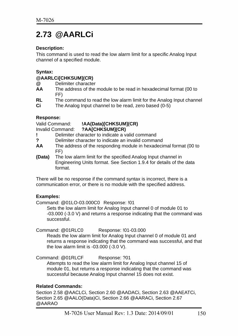
M-7026
2.73 @AARLCi Description: This command is used to read the low alarm limit for a specific Analog Input channel of a specified module. Syntax: @AARLCi[CHKSUM](CR) @ Delimiter character AA The address of the module to be read in hexadecimal format (00 to
FF) RL The command to read the low alarm limit for the Analog Input channel Ci The Analog Input channel to be read, zero based (0-5) Response: Valid Command: !AA(Data)[CHKSUM](CR) Invalid Command: ?AA[CHKSUM](CR) ! Delimiter character to indicate a valid command ? Delimiter character to indicate an invalid command AA The address of the responding module in hexadecimal format (00 to
FF) (Data) The low alarm limit for the specified Analog Input channel in
Engineering Units format. See Section 1.9.4 for details of the data format.
There will be no response if the command syntax is incorrect, there is a communication error, or there is no module with the specified address. Examples: Command: @01LO-03.000C0 Response: !01
Sets the low alarm limit for Analog Input channel 0 of module 01 to -03.000 (-3.0 V) and returns a response indicating that the command was successful.
Command: @01RLC0 Response: !01-03.000
Reads the low alarm limit for Analog Input channel 0 of module 01 and returns a response indicating that the command was successful, and that the low alarm limit is -03.000 (-3.0 V).
Command: @01RLCF Response: ?01
Attempts to read the low alarm limit for Analog Input channel 15 of module 01, but returns a response indicating that the command was successful because Analog Input channel 15 does not exist.
Related Commands: Section 2.58 @AACLCi, Section 2.60 @AADACi, Section 2.63 @AAEATCi, Section 2.65 @AALO(Data)Ci, Section 2.66 @AARACi, Section 2.67 @AARAO
M-7026 User Manual Rev: 1.3 Date: 2014/09/01 150

M-7026
Related Topics: Section 1.9.4 Analog Input Type Codes and Data Format
M-7026 User Manual Rev: 1.3 Date: 2014/09/01 151
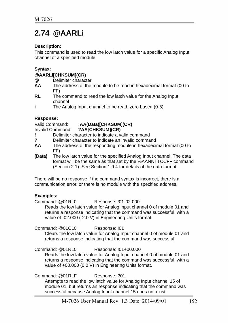
M-7026
2.74 @AARLi Description: This command is used to read the low latch value for a specific Analog Input channel of a specified module. Syntax: @AARLi[CHKSUM](CR) @ Delimiter character AA The address of the module to be read in hexadecimal format (00 to
FF) RL The command to read the low latch value for the Analog Input
channel i The Analog Input channel to be read, zero based (0-5) Response: Valid Command: !AA(Data)[CHKSUM](CR) Invalid Command: ?AA[CHKSUM](CR) ! Delimiter character to indicate a valid command ? Delimiter character to indicate an invalid command AA The address of the responding module in hexadecimal format (00 to
FF) (Data) The low latch value for the specified Analog Input channel. The data
format will be the same as that set by the %AANNTTCCFF command (Section 2.1). See Section 1.9.4 for details of the data format.
There will be no response if the command syntax is incorrect, there is a communication error, or there is no module with the specified address. Examples: Command: @01RL0 Response: !01-02.000
Reads the low latch value for Analog input channel 0 of module 01 and returns a response indicating that the command was successful, with a value of -02.000 (-2.0 V) in Engineering Units format.
Command: @01CL0 Response: !01
Clears the low latch value for Analog Input channel 0 of module 01 and returns a response indicating that the command was successful.
Command: @01RL0 Response: !01+00.000
Reads the low latch value for Analog Input channel 0 of module 01 and returns a response indicating that the command was successful, with a value of +00.000 (0.0 V) in Engineering Units format.
Command: @01RLF Response: ?01 Attempts to read the low latch value for Analog Input channel 15 of module 01, but returns an response indicating that the command was successful because Analog Input channel 15 does not exist.
M-7026 User Manual Rev: 1.3 Date: 2014/09/01 152

M-7026
Related Commands: Section 2.1 %AANNTTCCFF, Section 2.57 @AACL, Section 2.59 @AACLi, Section 2.72 @AARL Related Topics: Section 1.9.4 Analog Input Type Codes and Data Format
M-7026 User Manual Rev: 1.3 Date: 2014/09/01 153
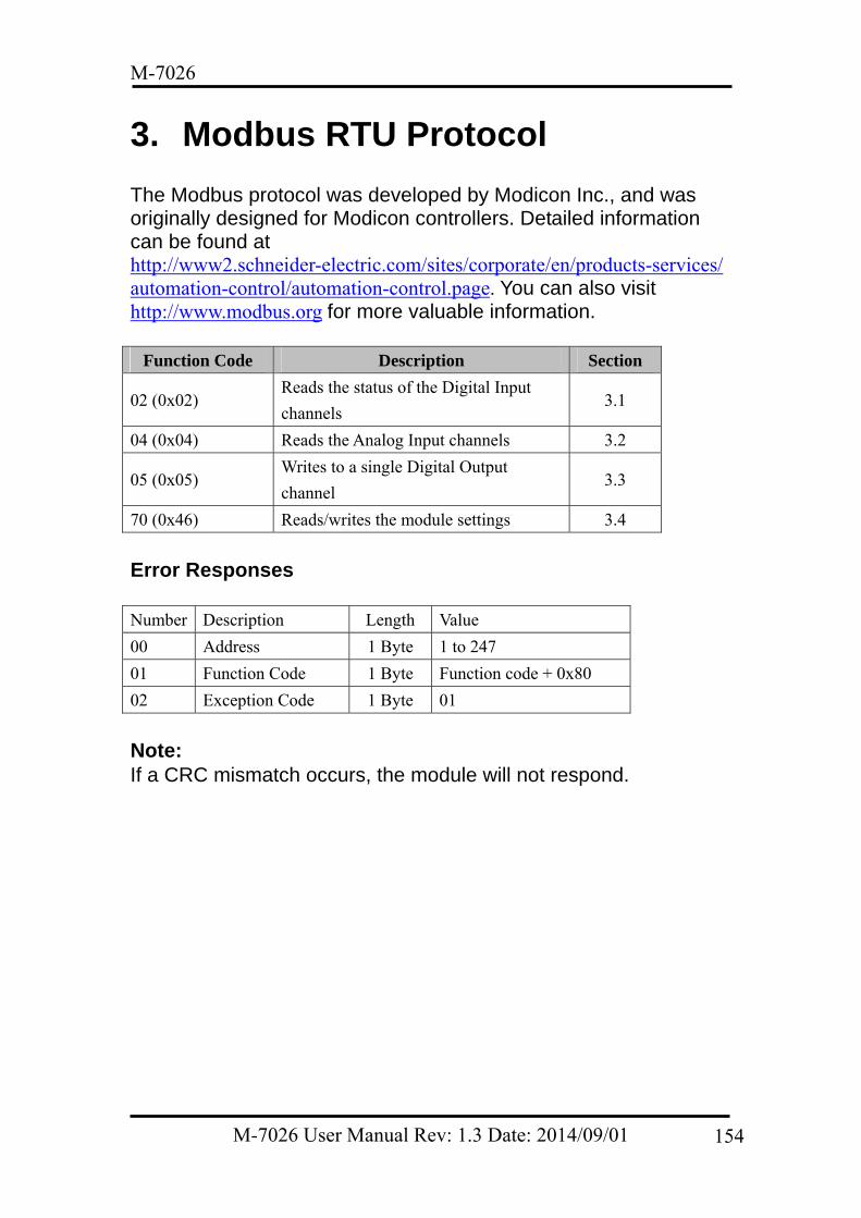
M-7026
3. Modbus RTU Protocol The Modbus protocol was developed by Modicon Inc., and was originally designed for Modicon controllers. Detailed information can be found at http://www2.schneider-electric.com/sites/corporate/en/products-services/automation-control/automation-control.page. You can also visit http://www.modbus.org for more valuable information.
Function Code Description Section
02 (0x02) Reads the status of the Digital Input
channels 3.1
04 (0x04) Reads the Analog Input channels 3.2
05 (0x05) Writes to a single Digital Output
channel 3.3
70 (0x46) Reads/writes the module settings 3.4
Error Responses Number Description Length Value
00 Address 1 Byte 1 to 247
01 Function Code 1 Byte Function code + 0x80
02 Exception Code 1 Byte 01
Note: If a CRC mismatch occurs, the module will not respond.
M-7026 User Manual Rev: 1.3 Date: 2014/09/01 154
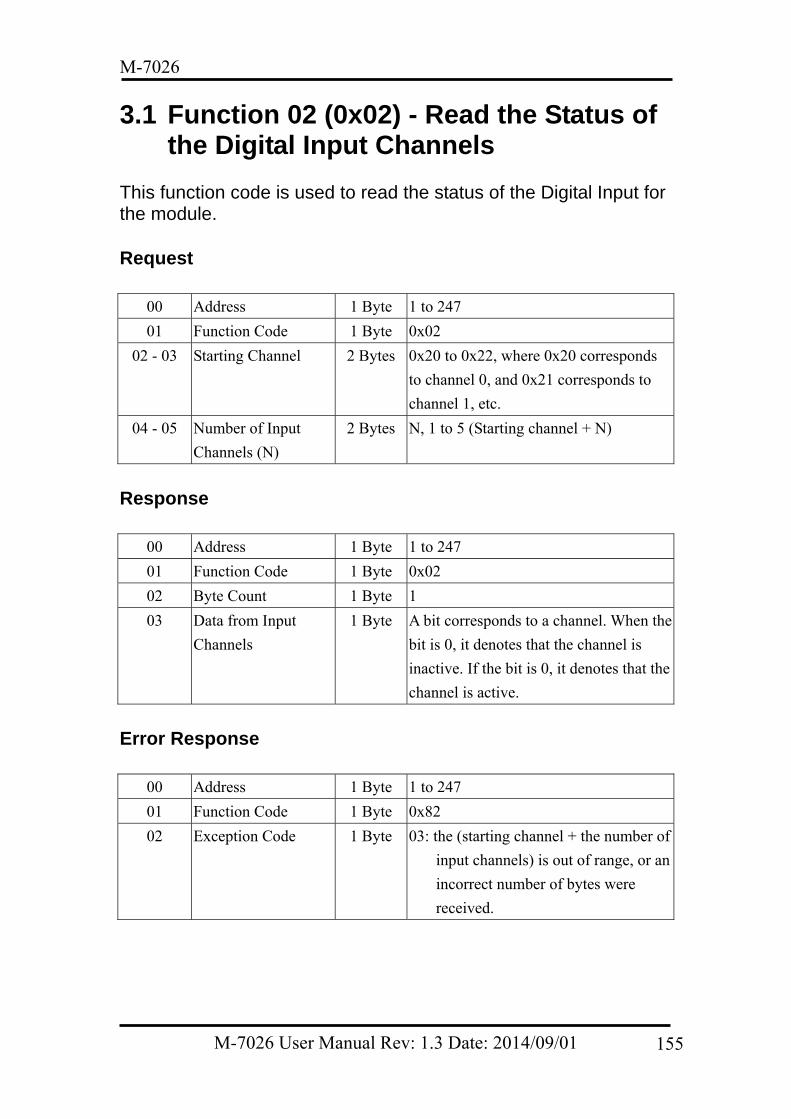
M-7026
3.1 Function 02 (0x02) - Read the Status of the Digital Input Channels
This function code is used to read the status of the Digital Input for the module. Request
00 Address 1 Byte 1 to 247
01 Function Code 1 Byte 0x02
02 - 03 Starting Channel 2 Bytes 0x20 to 0x22, where 0x20 corresponds
to channel 0, and 0x21 corresponds to
channel 1, etc.
04 - 05 Number of Input
Channels (N)
2 Bytes N, 1 to 5 (Starting channel + N)
Response
00 Address 1 Byte 1 to 247
01 Function Code 1 Byte 0x02
02 Byte Count 1 Byte 1
03 Data from Input
Channels
1 Byte A bit corresponds to a channel. When the
bit is 0, it denotes that the channel is
inactive. If the bit is 0, it denotes that the
channel is active.
Error Response
00 Address 1 Byte 1 to 247
01 Function Code 1 Byte 0x82
02 Exception Code 1 Byte 03: the (starting channel + the number of
input channels) is out of range, or an
incorrect number of bytes were
received.
M-7026 User Manual Rev: 1.3 Date: 2014/09/01 155
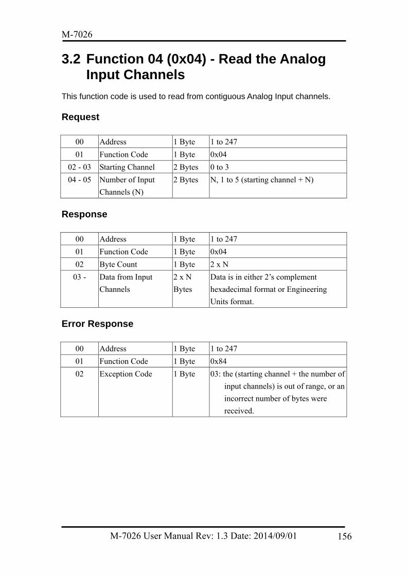
M-7026
3.2 Function 04 (0x04) - Read the Analog Input Channels
This function code is used to read from contiguous Analog Input channels.
Request
00 Address 1 Byte 1 to 247
01 Function Code 1 Byte 0x04
02 - 03 Starting Channel 2 Bytes 0 to 3
04 - 05 Number of Input
Channels (N)
2 Bytes N, 1 to 5 (starting channel + N)
Response
00 Address 1 Byte 1 to 247
01 Function Code 1 Byte 0x04
02 Byte Count 1 Byte 2 x N
03 - Data from Input
Channels
2 x N
Bytes
Data is in either 2’s complement
hexadecimal format or Engineering
Units format.
Error Response
00 Address 1 Byte 1 to 247
01 Function Code 1 Byte 0x84
02 Exception Code 1 Byte 03: the (starting channel + the number of
input channels) is out of range, or an
incorrect number of bytes were
received.
M-7026 User Manual Rev: 1.3 Date: 2014/09/01 156
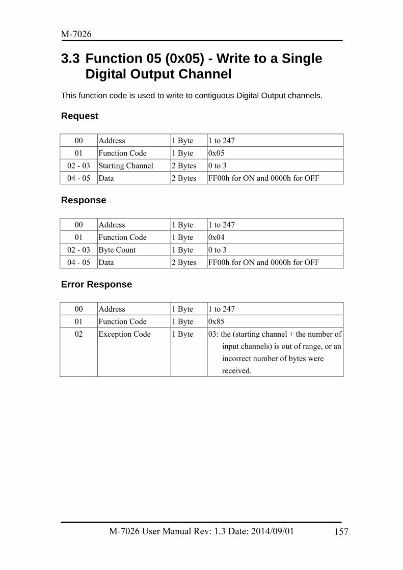
M-7026
3.3 Function 05 (0x05) - Write to a Single Digital Output Channel
This function code is used to write to contiguous Digital Output channels.
Request
00 Address 1 Byte 1 to 247
01 Function Code 1 Byte 0x05
02 - 03 Starting Channel 2 Bytes 0 to 3
04 - 05 Data 2 Bytes FF00h for ON and 0000h for OFF
Response
00 Address 1 Byte 1 to 247
01 Function Code 1 Byte 0x04
02 - 03 Byte Count 1 Byte 0 to 3
04 - 05 Data 2 Bytes FF00h for ON and 0000h for OFF
Error Response
00 Address 1 Byte 1 to 247
01 Function Code 1 Byte 0x85
02 Exception Code 1 Byte 03: the (starting channel + the number of
input channels) is out of range, or an
incorrect number of bytes were
received.
M-7026 User Manual Rev: 1.3 Date: 2014/09/01 157
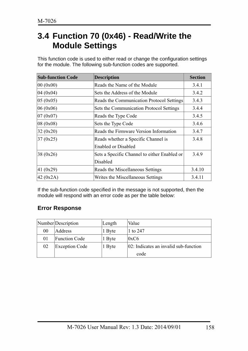
M-7026
3.4 Function 70 (0x46) - Read/Write the Module Settings
This function code is used to either read or change the configuration settings for the module. The following sub-function codes are supported.
Sub-function Code Description Section
00 (0x00) Reads the Name of the Module 3.4.1
04 (0x04) Sets the Address of the Module 3.4.2
05 (0x05) Reads the Communication Protocol Settings 3.4.3
06 (0x06) Sets the Communication Protocol Settings 3.4.4
07 (0x07) Reads the Type Code 3.4.5
08 (0x08) Sets the Type Code 3.4.6
32 (0x20) Reads the Firmware Version Information 3.4.7
37 (0x25) Reads whether a Specific Channel is
Enabled or Disabled
3.4.8
38 (0x26) Sets a Specific Channel to either Enabled or
Disabled
3.4.9
41 (0x29) Reads the Miscellaneous Settings 3.4.10
42 (0x2A) Writes the Miscellaneous Settings 3.4.11 If the sub-function code specified in the message is not supported, then the module will respond with an error code as per the table below:
Error Response
Number Description Length Value
00 Address 1 Byte 1 to 247
01 Function Code 1 Byte 0xC6
02 Exception Code 1 Byte 02: Indicates an invalid sub-function
code
M-7026 User Manual Rev: 1.3 Date: 2014/09/01 158
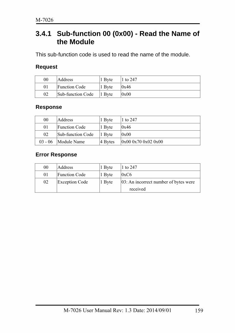
M-7026
3.4.1 Sub-function 00 (0x00) - Read the Name of the Module
This sub-function code is used to read the name of the module.
Request
00 Address 1 Byte 1 to 247
01 Function Code 1 Byte 0x46
02 Sub-function Code 1 Byte 0x00
Response
00 Address 1 Byte 1 to 247
01 Function Code 1 Byte 0x46
02 Sub-function Code 1 Byte 0x00
03 - 06 Module Name 4 Bytes 0x00 0x70 0x02 0x00
Error Response
00 Address 1 Byte 1 to 247
01 Function Code 1 Byte 0xC6
02 Exception Code 1 Byte 03: An incorrect number of bytes were
received
M-7026 User Manual Rev: 1.3 Date: 2014/09/01 159
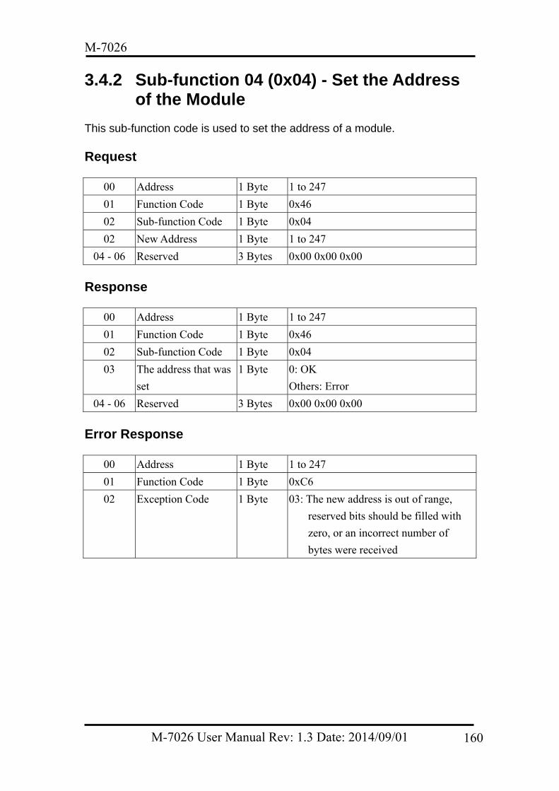
M-7026
3.4.2 Sub-function 04 (0x04) - Set the Address of the Module
This sub-function code is used to set the address of a module.
Request
00 Address 1 Byte 1 to 247
01 Function Code 1 Byte 0x46
02 Sub-function Code 1 Byte 0x04
02 New Address 1 Byte 1 to 247
04 - 06 Reserved 3 Bytes 0x00 0x00 0x00
Response
00 Address 1 Byte 1 to 247
01 Function Code 1 Byte 0x46
02 Sub-function Code 1 Byte 0x04
03 The address that was
set
1 Byte 0: OK
Others: Error
04 - 06 Reserved 3 Bytes 0x00 0x00 0x00
Error Response
00 Address 1 Byte 1 to 247
01 Function Code 1 Byte 0xC6
02 Exception Code 1 Byte 03: The new address is out of range,
reserved bits should be filled with
zero, or an incorrect number of
bytes were received
M-7026 User Manual Rev: 1.3 Date: 2014/09/01 160
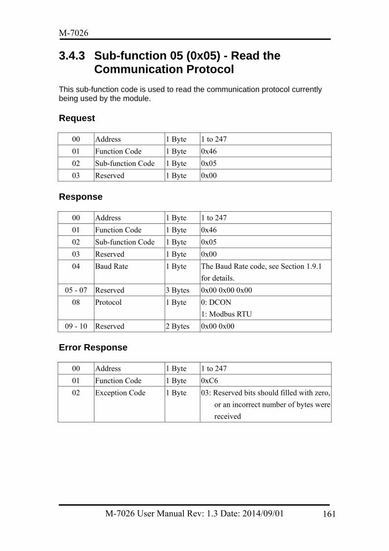
M-7026
3.4.3 Sub-function 05 (0x05) - Read the Communication Protocol
This sub-function code is used to read the communication protocol currently being used by the module.
Request
00 Address 1 Byte 1 to 247
01 Function Code 1 Byte 0x46
02 Sub-function Code 1 Byte 0x05
03 Reserved 1 Byte 0x00
Response
00 Address 1 Byte 1 to 247
01 Function Code 1 Byte 0x46
02 Sub-function Code 1 Byte 0x05
03 Reserved 1 Byte 0x00
04 Baud Rate 1 Byte The Baud Rate code, see Section 1.9.1
for details.
05 - 07 Reserved 3 Bytes 0x00 0x00 0x00
08 Protocol 1 Byte 0: DCON
1: Modbus RTU
09 - 10 Reserved 2 Bytes 0x00 0x00
Error Response
00 Address 1 Byte 1 to 247
01 Function Code 1 Byte 0xC6
02 Exception Code 1 Byte 03: Reserved bits should filled with zero,
or an incorrect number of bytes were
received
M-7026 User Manual Rev: 1.3 Date: 2014/09/01 161
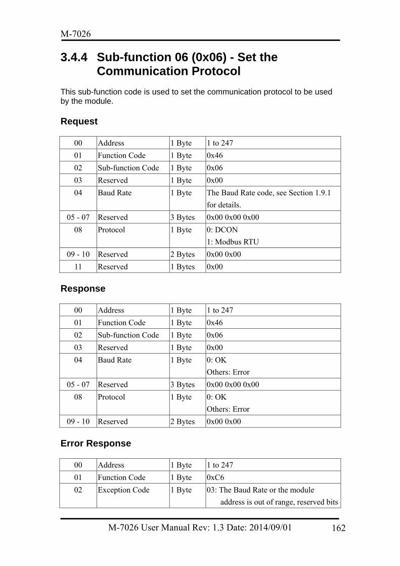
M-7026
3.4.4 Sub-function 06 (0x06) - Set the Communication Protocol
This sub-function code is used to set the communication protocol to be used by the module.
Request
00 Address 1 Byte 1 to 247
01 Function Code 1 Byte 0x46
02 Sub-function Code 1 Byte 0x06
03 Reserved 1 Byte 0x00
04 Baud Rate 1 Byte The Baud Rate code, see Section 1.9.1
for details.
05 - 07 Reserved 3 Bytes 0x00 0x00 0x00
08 Protocol 1 Byte 0: DCON
1: Modbus RTU
09 - 10 Reserved 2 Bytes 0x00 0x00
11 Reserved 1 Bytes 0x00
Response
00 Address 1 Byte 1 to 247
01 Function Code 1 Byte 0x46
02 Sub-function Code 1 Byte 0x06
03 Reserved 1 Byte 0x00
04 Baud Rate 1 Byte 0: OK
Others: Error
05 - 07 Reserved 3 Bytes 0x00 0x00 0x00
08 Protocol 1 Byte 0: OK
Others: Error
09 - 10 Reserved 2 Bytes 0x00 0x00
Error Response
00 Address 1 Byte 1 to 247
01 Function Code 1 Byte 0xC6
02 Exception Code 1 Byte 03: The Baud Rate or the module
address is out of range, reserved bits
M-7026 User Manual Rev: 1.3 Date: 2014/09/01 162
M-7026
should be filled with zero, or an
incorrect number of bytes were
received
M-7026 User Manual Rev: 1.3 Date: 2014/09/01 163
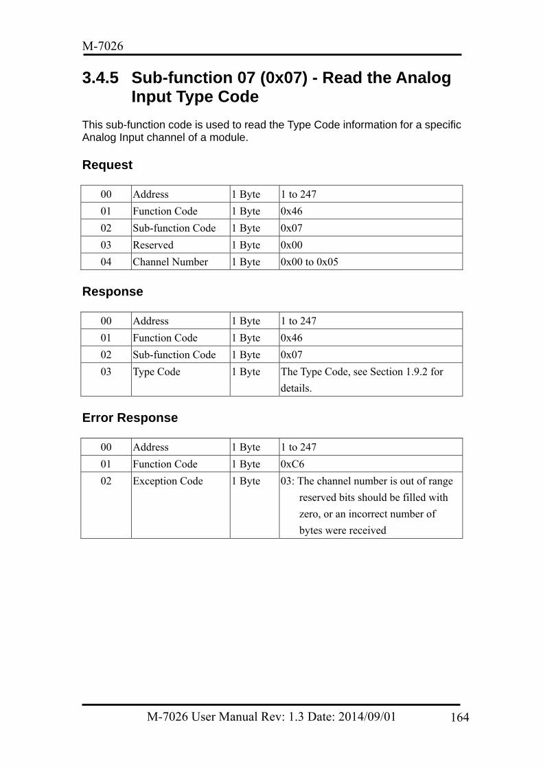
M-7026
3.4.5 Sub-function 07 (0x07) - Read the Analog Input Type Code
This sub-function code is used to read the Type Code information for a specific Analog Input channel of a module.
Request
00 Address 1 Byte 1 to 247
01 Function Code 1 Byte 0x46
02 Sub-function Code 1 Byte 0x07
03 Reserved 1 Byte 0x00
04 Channel Number 1 Byte 0x00 to 0x05
Response
00 Address 1 Byte 1 to 247
01 Function Code 1 Byte 0x46
02 Sub-function Code 1 Byte 0x07
03 Type Code 1 Byte The Type Code, see Section 1.9.2 for
details.
Error Response
00 Address 1 Byte 1 to 247
01 Function Code 1 Byte 0xC6
02 Exception Code 1 Byte 03: The channel number is out of range
reserved bits should be filled with
zero, or an incorrect number of
bytes were received
M-7026 User Manual Rev: 1.3 Date: 2014/09/01 164
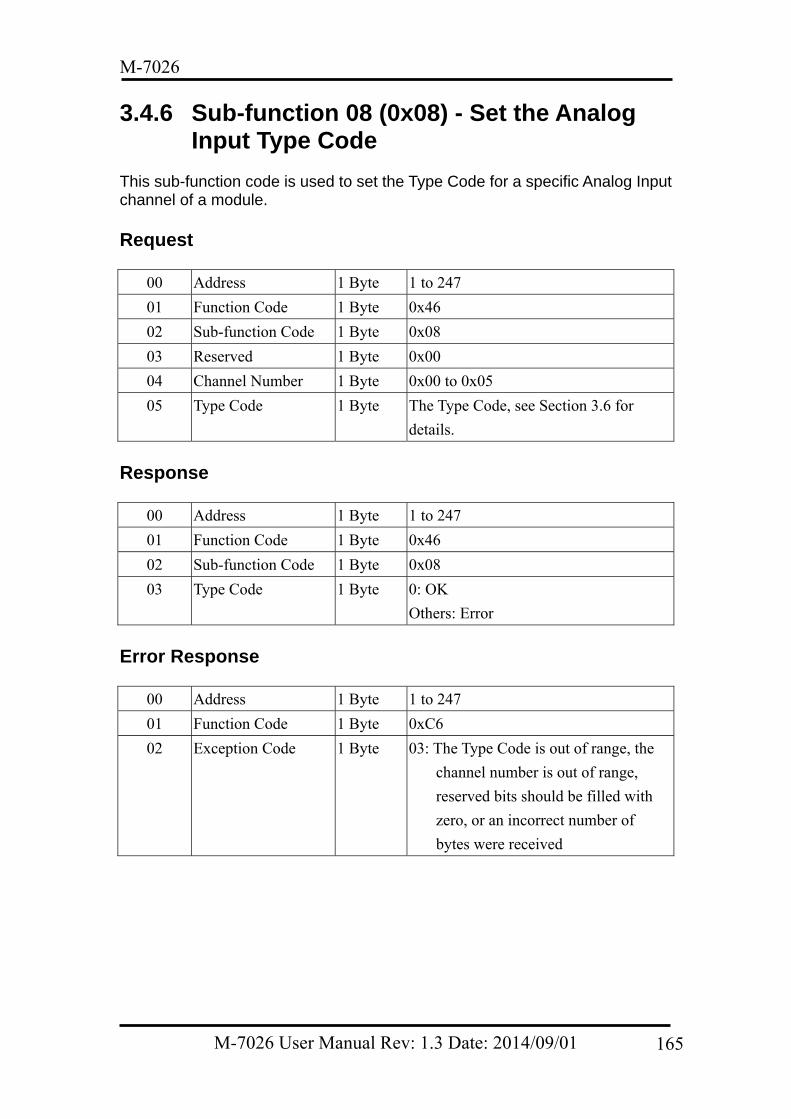
M-7026
3.4.6 Sub-function 08 (0x08) - Set the Analog Input Type Code
This sub-function code is used to set the Type Code for a specific Analog Input channel of a module.
Request
00 Address 1 Byte 1 to 247
01 Function Code 1 Byte 0x46
02 Sub-function Code 1 Byte 0x08
03 Reserved 1 Byte 0x00
04 Channel Number 1 Byte 0x00 to 0x05
05 Type Code 1 Byte The Type Code, see Section 3.6 for
details.
Response
00 Address 1 Byte 1 to 247
01 Function Code 1 Byte 0x46
02 Sub-function Code 1 Byte 0x08
03 Type Code 1 Byte 0: OK
Others: Error
Error Response
00 Address 1 Byte 1 to 247
01 Function Code 1 Byte 0xC6
02 Exception Code 1 Byte 03: The Type Code is out of range, the
channel number is out of range,
reserved bits should be filled with
zero, or an incorrect number of
bytes were received
M-7026 User Manual Rev: 1.3 Date: 2014/09/01 165
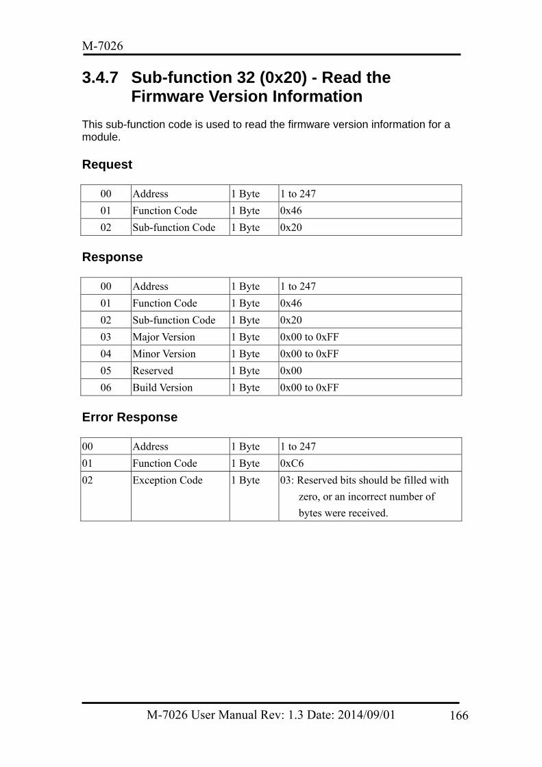
M-7026
3.4.7 Sub-function 32 (0x20) - Read the Firmware Version Information
This sub-function code is used to read the firmware version information for a module.
Request
00 Address 1 Byte 1 to 247
01 Function Code 1 Byte 0x46
02 Sub-function Code 1 Byte 0x20
Response
00 Address 1 Byte 1 to 247
01 Function Code 1 Byte 0x46
02 Sub-function Code 1 Byte 0x20
03 Major Version 1 Byte 0x00 to 0xFF
04 Minor Version 1 Byte 0x00 to 0xFF
05 Reserved 1 Byte 0x00
06 Build Version 1 Byte 0x00 to 0xFF
Error Response 00 Address 1 Byte 1 to 247
01 Function Code 1 Byte 0xC6
02 Exception Code 1 Byte 03: Reserved bits should be filled with
zero, or an incorrect number of
bytes were received.
M-7026 User Manual Rev: 1.3 Date: 2014/09/01 166
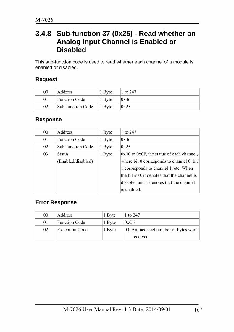
M-7026
3.4.8 Sub-function 37 (0x25) - Read whether an Analog Input Channel is Enabled or Disabled
This sub-function code is used to read whether each channel of a module is enabled or disabled.
Request
00 Address 1 Byte 1 to 247
01 Function Code 1 Byte 0x46
02 Sub-function Code 1 Byte 0x25
Response
00 Address 1 Byte 1 to 247
01 Function Code 1 Byte 0x46
02 Sub-function Code 1 Byte 0x25
03 Status
(Enabled/disabled)
1 Byte 0x00 to 0x0F, the status of each channel,
where bit 0 corresponds to channel 0, bit
1 corresponds to channel 1, etc. When
the bit is 0, it denotes that the channel is
disabled and 1 denotes that the channel
is enabled.
Error Response
00 Address 1 Byte 1 to 247
01 Function Code 1 Byte 0xC6
02 Exception Code 1 Byte 03: An incorrect number of bytes were
received
M-7026 User Manual Rev: 1.3 Date: 2014/09/01 167
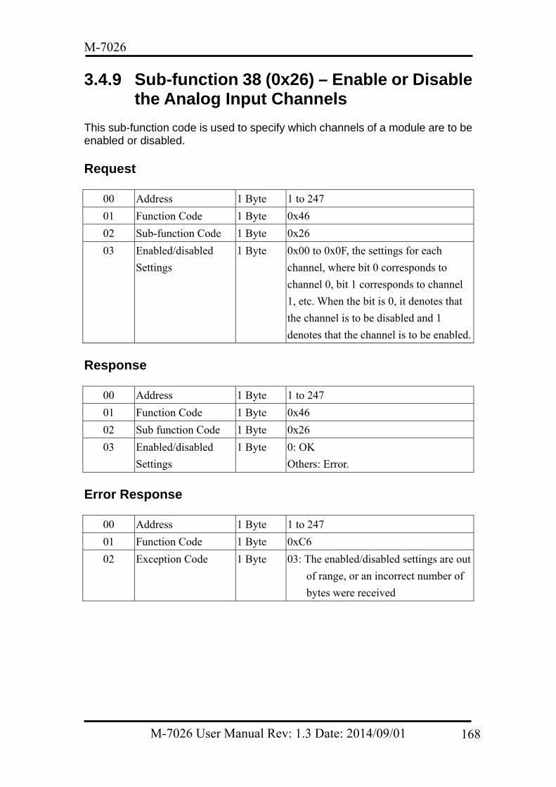
M-7026
3.4.9 Sub-function 38 (0x26) – Enable or Disable the Analog Input Channels
This sub-function code is used to specify which channels of a module are to be enabled or disabled.
Request
00 Address 1 Byte 1 to 247
01 Function Code 1 Byte 0x46
02 Sub-function Code 1 Byte 0x26
03 Enabled/disabled
Settings
1 Byte 0x00 to 0x0F, the settings for each
channel, where bit 0 corresponds to
channel 0, bit 1 corresponds to channel
1, etc. When the bit is 0, it denotes that
the channel is to be disabled and 1
denotes that the channel is to be enabled.
Response
00 Address 1 Byte 1 to 247
01 Function Code 1 Byte 0x46
02 Sub function Code 1 Byte 0x26
03 Enabled/disabled
Settings
1 Byte 0: OK
Others: Error.
Error Response
00 Address 1 Byte 1 to 247
01 Function Code 1 Byte 0xC6
02 Exception Code 1 Byte 03: The enabled/disabled settings are out
of range, or an incorrect number of
bytes were received
M-7026 User Manual Rev: 1.3 Date: 2014/09/01 168
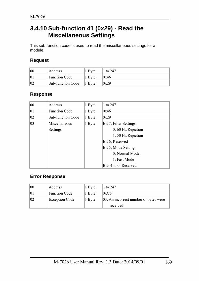
M-7026
3.4.10 Sub-function 41 (0x29) - Read the Miscellaneous Settings
This sub-function code is used to read the miscellaneous settings for a module.
Request 00 Address 1 Byte 1 to 247
01 Function Code 1 Byte 0x46
02 Sub-function Code 1 Byte 0x29
Response 00 Address 1 Byte 1 to 247
01 Function Code 1 Byte 0x46
02 Sub-function Code 1 Byte 0x29
03 Miscellaneous
Settings
1 Byte Bit 7: Filter Settings
0: 60 Hz Rejection
1: 50 Hz Rejection
Bit 6: Reserved
Bit 5: Mode Settings
0: Normal Mode
1: Fast Mode
Bits 4 to 0: Reserved
Error Response 00 Address 1 Byte 1 to 247
01 Function Code 1 Byte 0xC6
02 Exception Code 1 Byte 03: An incorrect number of bytes were
received
M-7026 User Manual Rev: 1.3 Date: 2014/09/01 169
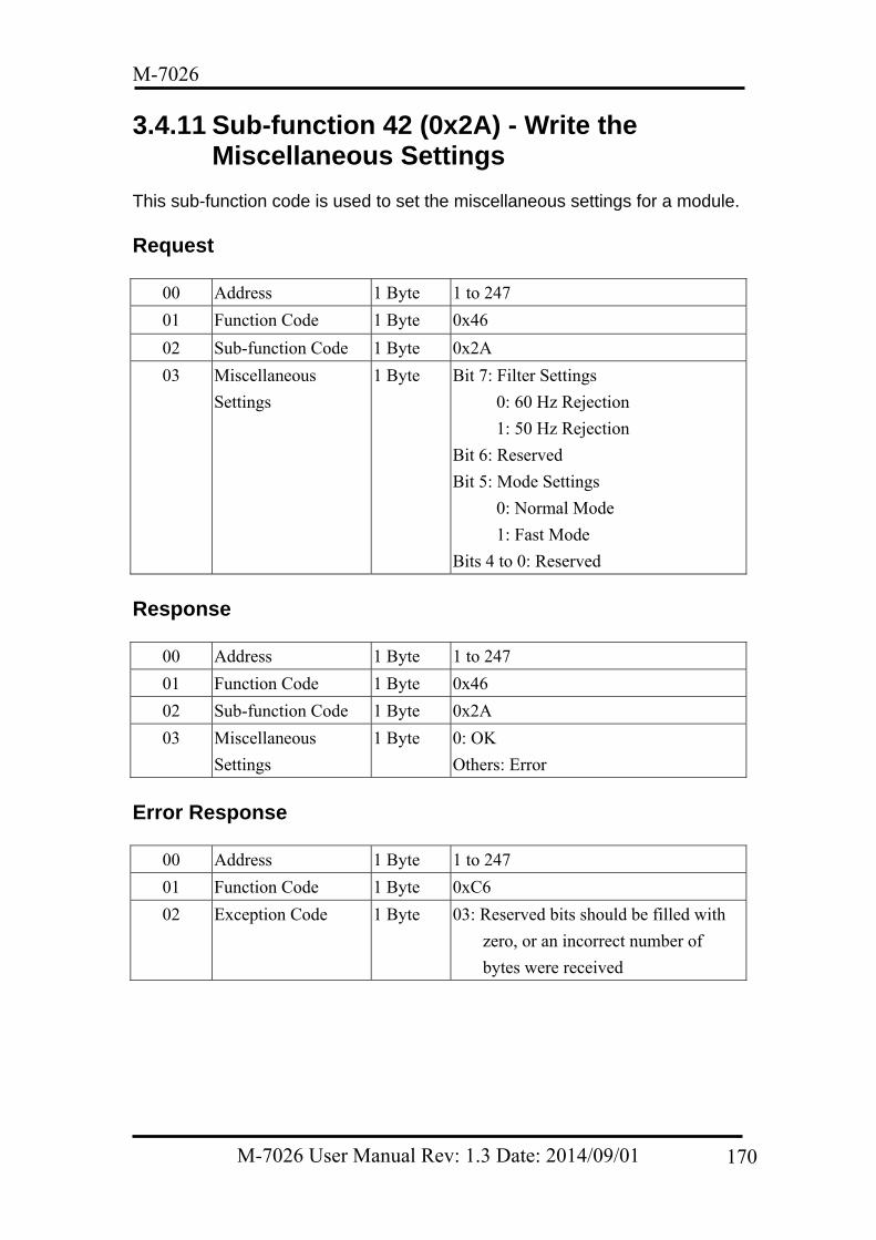
M-7026
3.4.11 Sub-function 42 (0x2A) - Write the Miscellaneous Settings
This sub-function code is used to set the miscellaneous settings for a module.
Request
00 Address 1 Byte 1 to 247
01 Function Code 1 Byte 0x46
02 Sub-function Code 1 Byte 0x2A
03 Miscellaneous
Settings
1 Byte Bit 7: Filter Settings
0: 60 Hz Rejection
1: 50 Hz Rejection
Bit 6: Reserved
Bit 5: Mode Settings
0: Normal Mode
1: Fast Mode
Bits 4 to 0: Reserved
Response
00 Address 1 Byte 1 to 247
01 Function Code 1 Byte 0x46
02 Sub-function Code 1 Byte 0x2A
03 Miscellaneous
Settings
1 Byte 0: OK
Others: Error
Error Response
00 Address 1 Byte 1 to 247
01 Function Code 1 Byte 0xC6
02 Exception Code 1 Byte 03: Reserved bits should be filled with
zero, or an incorrect number of
bytes were received
M-7026 User Manual Rev: 1.3 Date: 2014/09/01 170
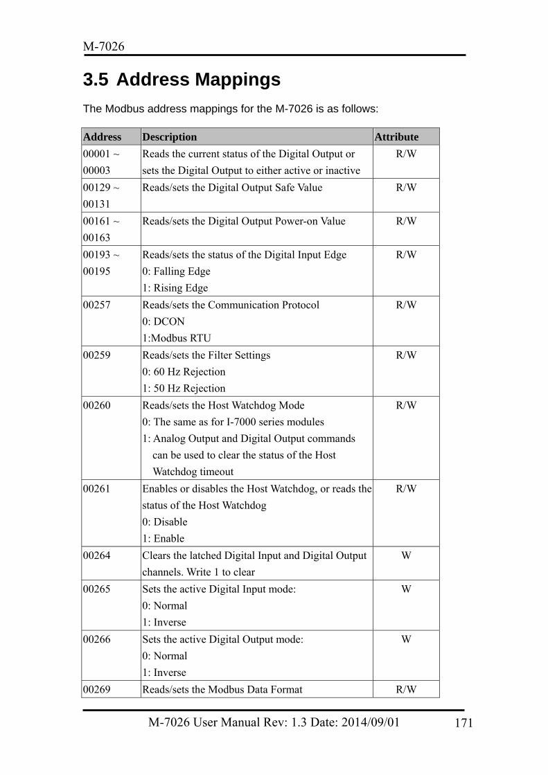
M-7026
3.5 Address Mappings The Modbus address mappings for the M-7026 is as follows:
Address Description Attribute
00001 ~
00003
Reads the current status of the Digital Output or
sets the Digital Output to either active or inactive
R/W
00129 ~
00131
Reads/sets the Digital Output Safe Value R/W
00161 ~
00163
Reads/sets the Digital Output Power-on Value R/W
00193 ~
00195
Reads/sets the status of the Digital Input Edge
0: Falling Edge
1: Rising Edge
R/W
00257 Reads/sets the Communication Protocol
0: DCON
1:Modbus RTU
R/W
00259 Reads/sets the Filter Settings
0: 60 Hz Rejection
1: 50 Hz Rejection
R/W
00260 Reads/sets the Host Watchdog Mode
0: The same as for I-7000 series modules
1: Analog Output and Digital Output commands
can be used to clear the status of the Host
Watchdog timeout
R/W
00261 Enables or disables the Host Watchdog, or reads the
status of the Host Watchdog
0: Disable
1: Enable
R/W
00264 Clears the latched Digital Input and Digital Output
channels. Write 1 to clear
W
00265 Sets the active Digital Input mode:
0: Normal
1: Inverse
W
00266 Sets the active Digital Output mode:
0: Normal
1: Inverse
W
00269 Reads/sets the Modbus Data Format R/W
M-7026 User Manual Rev: 1.3 Date: 2014/09/01 171
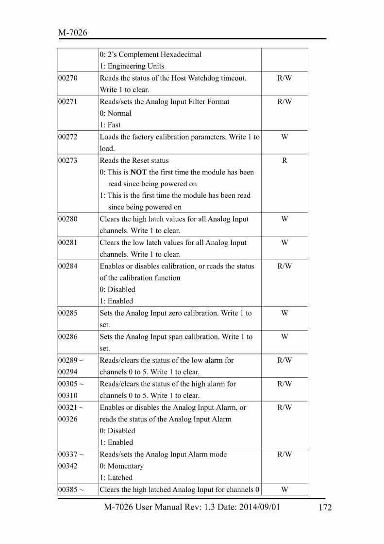
M-7026
0: 2’s Complement Hexadecimal
1: Engineering Units
00270 Reads the status of the Host Watchdog timeout.
Write 1 to clear.
R/W
00271 Reads/sets the Analog Input Filter Format
0: Normal
1: Fast
R/W
00272 Loads the factory calibration parameters. Write 1 to
load.
W
00273 Reads the Reset status
0: This is NOT the first time the module has been
read since being powered on
1: This is the first time the module has been read
since being powered on
R
00280 Clears the high latch values for all Analog Input
channels. Write 1 to clear.
W
00281 Clears the low latch values for all Analog Input
channels. Write 1 to clear.
W
00284 Enables or disables calibration, or reads the status
of the calibration function
0: Disabled
1: Enabled
R/W
00285 Sets the Analog Input zero calibration. Write 1 to
set.
W
00286 Sets the Analog Input span calibration. Write 1 to
set.
W
00289 ~
00294
Reads/clears the status of the low alarm for
channels 0 to 5. Write 1 to clear.
R/W
00305 ~
00310
Reads/clears the status of the high alarm for
channels 0 to 5. Write 1 to clear.
R/W
00321 ~
00326
Enables or disables the Analog Input Alarm, or
reads the status of the Analog Input Alarm
0: Disabled
1: Enabled
R/W
00337 ~
00342
Reads/sets the Analog Input Alarm mode
0: Momentary
1: Latched
R/W
00385 ~ Clears the high latched Analog Input for channels 0 W
M-7026 User Manual Rev: 1.3 Date: 2014/09/01 172
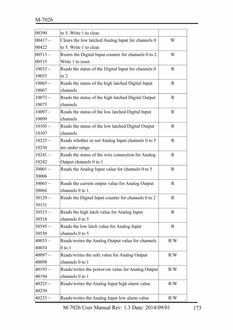
M-7026
00390 to 5. Write 1 to clear.
00417 ~
00422
Clears the low latched Analog Input for channels 0
to 5. Write 1 to clear.
W
00513 ~
00515
Resets the Digital Input counter for channels 0 to 2.
Write 1 to reset.
W
10033 ~
10035
Reads the status of the Digital Input for channels 0
to 2
R
10065 ~
10067
Reads the status of the high latched Digital Input
channels
R
10073 ~
10075
Reads the status of the high latched Digital Output
channels
R
10097~
10099
Reads the status of the low latched Digital Input
channels
R
10105 ~
10107
Reads the status of the low latched Digital Output
channels
R
10225 ~
10230
Reads whether or not Analog Input channels 0 to 5
are under range
R
10241 ~
10242
Reads the status of the wire connection for Analog
Output channels 0 to 1
R
30001 ~
30006
Reads the Analog Input value for channels 0 to 5 R
30065 ~
30066
Reads the current output value for Analog Output
channels 0 to 1
R
30129 ~
30131
Reads the Digital Input counter for channels 0 to 2 R
30513 ~
30518
Reads the high latch value for Analog Input
channels 0 to 5
R
30545 ~
30550
Reads the low latch value for Analog Input
channels 0 to 5
R
40033 ~
40034
Reads/writes the Analog Output value for channels
0 to 1
R/W
40097 ~
40098
Reads/writes the safe value for Analog Output
channels 0 to 1
R/W
40193 ~
40194
Reads/writes the power-on value for Analog Output
channels 0 to 1
R/W
40225 ~
40230
Reads/writes the Analog Input high alarm value R/W
40233 ~ Reads/writes the Analog Input low alarm value R/W
M-7026 User Manual Rev: 1.3 Date: 2014/09/01 173
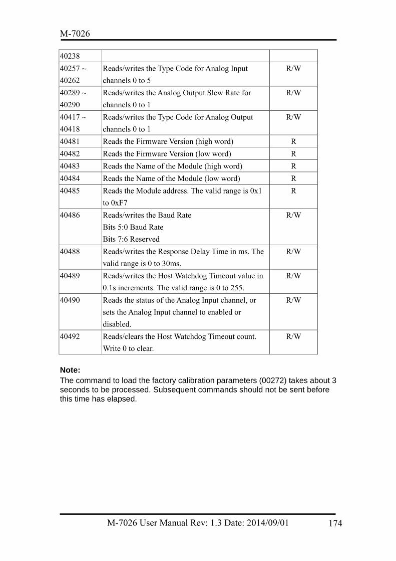
M-7026
40238
40257 ~
40262
Reads/writes the Type Code for Analog Input
channels 0 to 5
R/W
40289 ~
40290
Reads/writes the Analog Output Slew Rate for
channels 0 to 1
R/W
40417 ~
40418
Reads/writes the Type Code for Analog Output
channels 0 to 1
R/W
40481 Reads the Firmware Version (high word) R
40482 Reads the Firmware Version (low word) R
40483 Reads the Name of the Module (high word) R
40484 Reads the Name of the Module (low word) R
40485 Reads the Module address. The valid range is 0x1
to 0xF7
R
40486 Reads/writes the Baud Rate
Bits 5:0 Baud Rate
Bits 7:6 Reserved
R/W
40488 Reads/writes the Response Delay Time in ms. The
valid range is 0 to 30ms.
R/W
40489 Reads/writes the Host Watchdog Timeout value in
0.1s increments. The valid range is 0 to 255.
R/W
40490 Reads the status of the Analog Input channel, or
sets the Analog Input channel to enabled or
disabled.
R/W
40492 Reads/clears the Host Watchdog Timeout count.
Write 0 to clear.
R/W
Note: The command to load the factory calibration parameters (00272) takes about 3 seconds to be processed. Subsequent commands should not be sent before this time has elapsed.
M-7026 User Manual Rev: 1.3 Date: 2014/09/01 174
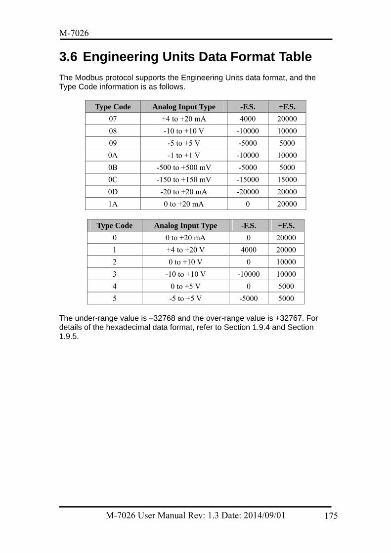
M-7026
3.6 Engineering Units Data Format Table The Modbus protocol supports the Engineering Units data format, and the Type Code information is as follows.
Type Code Analog Input Type -F.S. +F.S.
07 +4 to +20 mA 4000 20000
08 -10 to +10 V -10000 10000
09 -5 to +5 V -5000 5000
0A -1 to +1 V -10000 10000
0B -500 to +500 mV -5000 5000
0C -150 to +150 mV -15000 15000
0D -20 to +20 mA -20000 20000
1A 0 to +20 mA 0 20000
Type Code Analog Input Type -F.S. +F.S.
0 0 to +20 mA 0 20000
1 +4 to +20 V 4000 20000
2 0 to +10 V 0 10000
3 -10 to +10 V -10000 10000
4 0 to +5 V 0 5000
5 -5 to +5 V -5000 5000 The under-range value is –32768 and the over-range value is +32767. For details of the hexadecimal data format, refer to Section 1.9.4 and Section 1.9.5.
M-7026 User Manual Rev: 1.3 Date: 2014/09/01 175
M-7026
4. Troubleshooting If you are having difficulties using your M-7026 module, here are some suggestions that may help. If you cannot find the answers you need in this guide, contact ICP DAS Product Support.
4.1 Communicating with the Module If you attempt to communicate with the module and receive no response, first check the following: Ensure that the supplied power is within the range of +10 to +30 VDC. If the
supplied power is sufficient, then the power LED should be on. When the module receives a command, the power LED will be set to
“OFF”. The power LED will be shown as “ON” after the module responds. This method can be used to check whether or not the module has received a command sent from the host.
If possible, use another device that is known to be functional to check whether the host can communicate with the device through the same network.
If the host is a PC installed with a Windows operating system, execute the DCON Utility to determine whether the module can be found. The DCON Utility can be downloaded from the ICP DAS website at http://www.icpdas.com. Documentation for the DCON Utility can be found in the “Getting Started for I-7000 Series Modules” manual.
Set the module to “INIT mode” and communicate with the module using address 00 and the DCON protocol. See Section 1.9 for more details related to configuration settings.
4.2 Reading Data If the data read from the input channel is not correct, first check the following: Ensure that the Type Code and data format settings are correct. The Type
Code is set by using the $AA7CiRrr command (see Section 2.18). The data format is set by using the %AANNTTCCFF command (see Section 2.1). If you are using the Modbus RTU protocol, the Type Code is set by using sub-function 08h of the 46h function.
If the voltage read by the module is incorrect, it may be because the calibration parameters stored in the non-volatile memory are corrupted. You can calibrate the module by yourself, but be sure to read the information contained in Section 1.8 before performing any calibration. Use the $AAS1 command (Section 2.35) to reload the factory calibration parameters.
M-7026 User Manual Rev: 1.3 Date: 2014/09/01 176
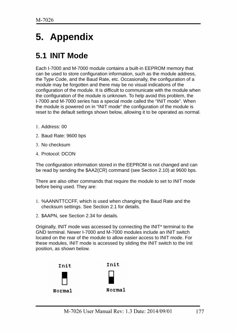
M-7026
5. Appendix
5.1 INIT Mode Each I-7000 and M-7000 module contains a built-in EEPROM memory that can be used to store configuration information, such as the module address, the Type Code, and the Baud Rate, etc. Occasionally, the configuration of a module may be forgotten and there may be no visual indications of the configuration of the module. It is difficult to communicate with the module when the configuration of the module is unknown. To help avoid this problem, the I-7000 and M-7000 series has a special mode called the “INIT mode”. When the module is powered on in “INIT mode” the configuration of the module is reset to the default settings shown below, allowing it to be operated as normal.
1. Address: 00
2. Baud Rate: 9600 bps
3. No checksum
4. Protocol: DCON The configuration information stored in the EEPROM is not changed and can be read by sending the $AA2(CR) command (see Section 2.10) at 9600 bps. There are also other commands that require the module to set to INIT mode before being used. They are:
1. %AANNTTCCFF, which is used when changing the Baud Rate and the checksum settings. See Section 2.1 for details.
2. $AAPN, see Section 2.34 for details. Originally, INIT mode was accessed by connecting the INIT* terminal to the GND terminal. Newer I-7000 and M-7000 modules include an INIT switch located on the rear of the module to allow easier access to INIT mode. For these modules, INIT mode is accessed by sliding the INIT switch to the Init position, as shown below.
M-7026 User Manual Rev: 1.3 Date: 2014/09/01 177
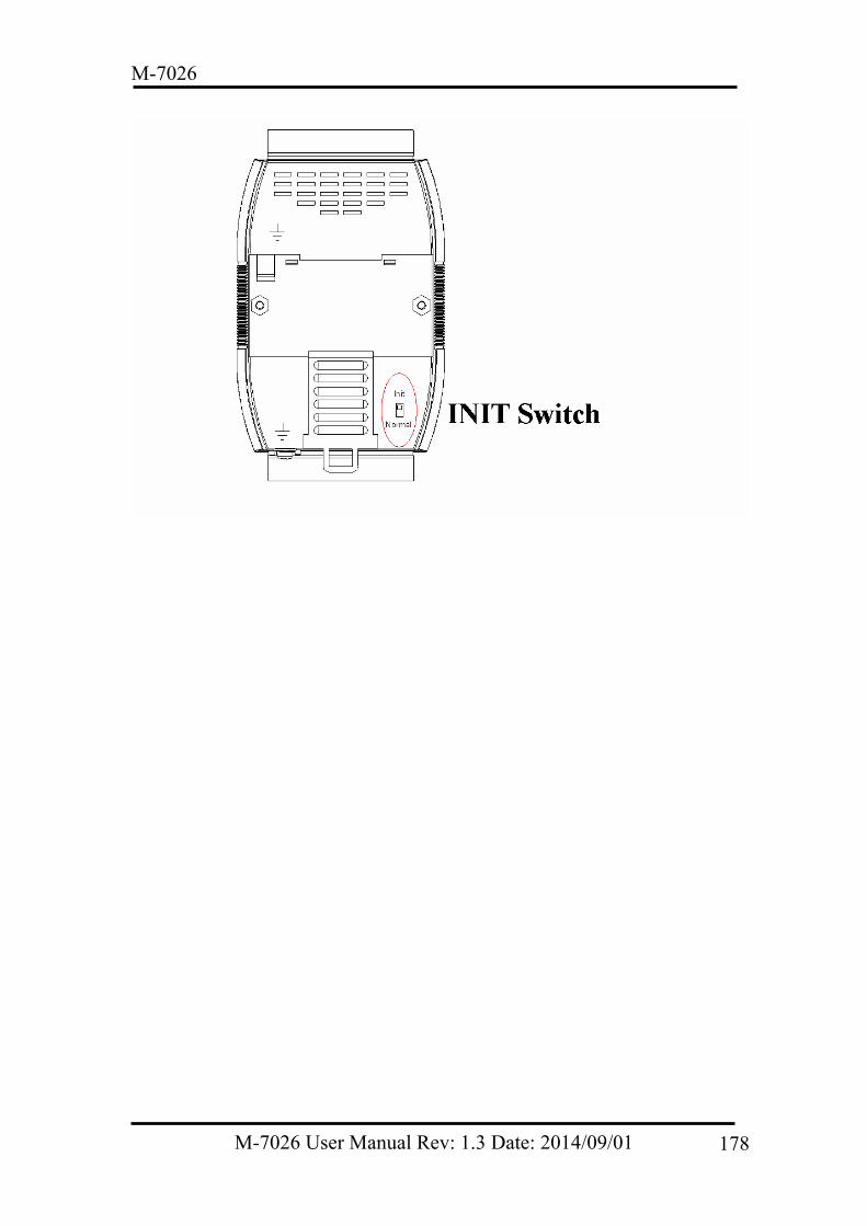
M-7026
M-7026 User Manual Rev: 1.3 Date: 2014/09/01 178
M-7026
5.2 Dual Watchdog Operation Dual Watchdog = Module Watchdog + Host Watchdog The Module Watchdog is a hardware reset circuit that monitors the operating status of the module. While working in harsh or noisy environments, the module may be shut down by external signals. The Watchdog circuit allows the module to operate continuously without disruption. The Host Watchdog is a software function that monitors the operating status of the host. Its purpose is to prevent problems due to network/communication errors or host malfunctions. When a Host Watchdog timeout occurs, the module will reset all outputs to a safe state in order to prevent the controlled target from performing any erroneous operations. M-7000 series modules include an internal Dual Watchdog, making the control system more reliable and stable. For more information regarding the Dual Watchdog, refer to Chapter 5 of the “Getting Started for M-7026 Modules” manual that can be downloaded from the ICP DAS website
M-7026 User Manual Rev: 1.3 Date: 2014/09/01 179
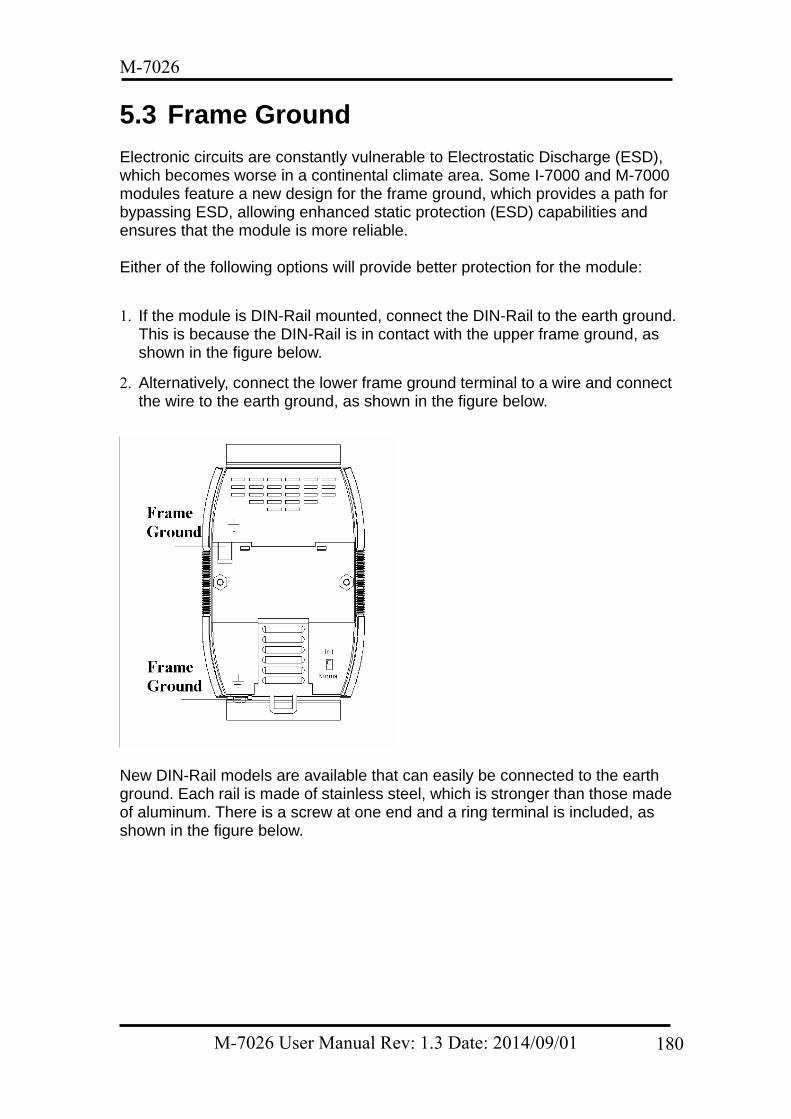
M-7026
5.3 Frame Ground Electronic circuits are constantly vulnerable to Electrostatic Discharge (ESD), which becomes worse in a continental climate area. Some I-7000 and M-7000 modules feature a new design for the frame ground, which provides a path for bypassing ESD, allowing enhanced static protection (ESD) capabilities and ensures that the module is more reliable. Either of the following options will provide better protection for the module:
1. If the module is DIN-Rail mounted, connect the DIN-Rail to the earth ground. This is because the DIN-Rail is in contact with the upper frame ground, as shown in the figure below.
2. Alternatively, connect the lower frame ground terminal to a wire and connect the wire to the earth ground, as shown in the figure below.
New DIN-Rail models are available that can easily be connected to the earth ground. Each rail is made of stainless steel, which is stronger than those made of aluminum. There is a screw at one end and a ring terminal is included, as shown in the figure below.
M-7026 User Manual Rev: 1.3 Date: 2014/09/01 180
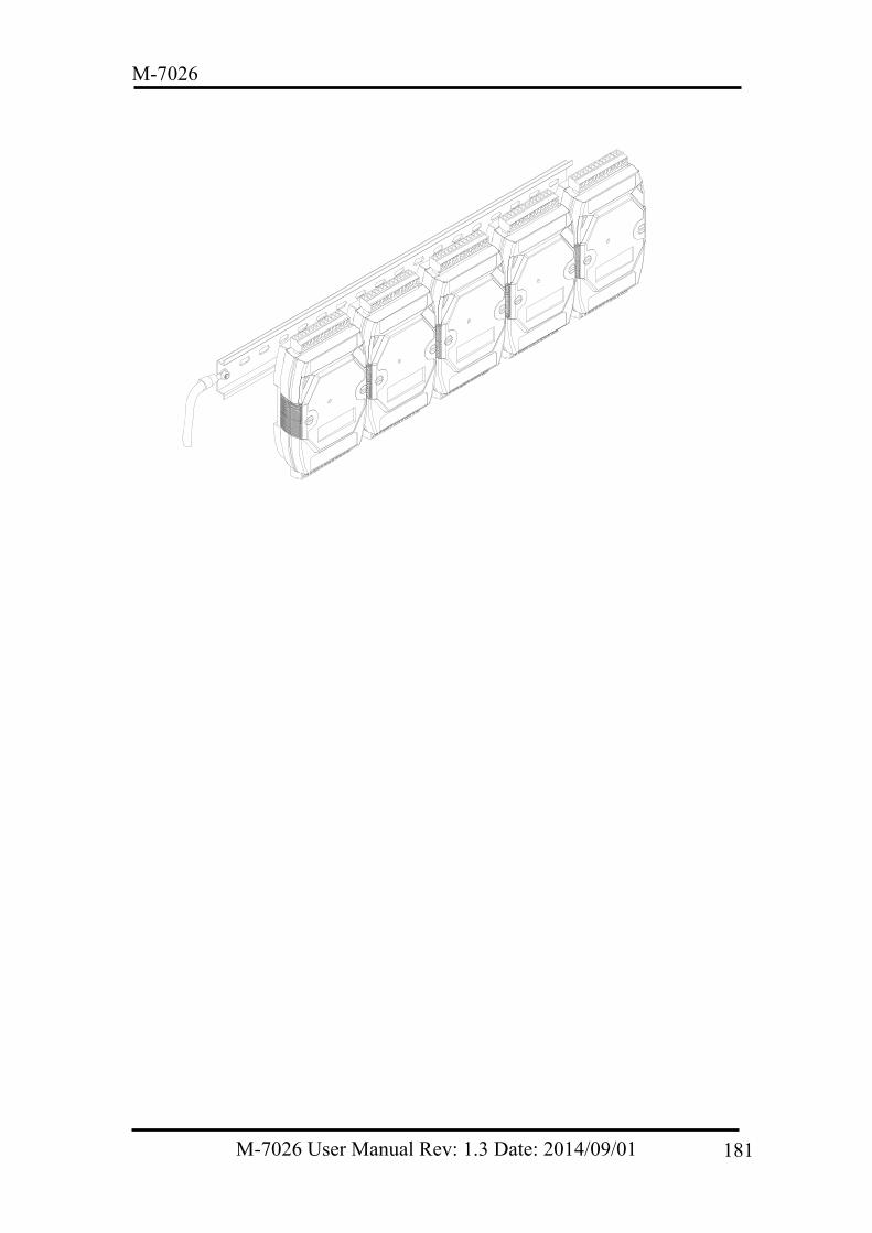
M-7026
M-7026 User Manual Rev: 1.3 Date: 2014/09/01 181
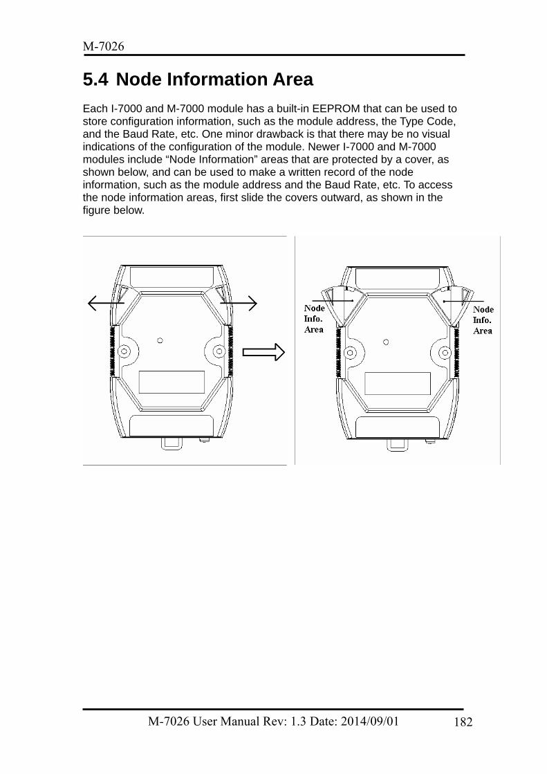
M-7026
5.4 Node Information Area Each I-7000 and M-7000 module has a built-in EEPROM that can be used to store configuration information, such as the module address, the Type Code, and the Baud Rate, etc. One minor drawback is that there may be no visual indications of the configuration of the module. Newer I-7000 and M-7000 modules include “Node Information” areas that are protected by a cover, as shown below, and can be used to make a written record of the node information, such as the module address and the Baud Rate, etc. To access the node information areas, first slide the covers outward, as shown in the figure below.
M-7026 User Manual Rev: 1.3 Date: 2014/09/01 182
M-7026
M-7026 User Manual Rev: 1.3 Date: 2014/09/01 183
5.5 Reset Status The reset status of a module is set when the module is first powered on, or when the module is reset by the Module Watchdog, and is cleared after responding to the first $AA5 command (see Section 2.14). This command can be used to check whether the module has recently been reset. If the response from the $AA5 command indicates that the reset status has been cleared, it means that the module has not been reset since the last $AA5 command was sent. If the response from the $AA5 command indicates that the reset status is set and it is not the first time an $AA5 command has been sent, it means that the module has been reset and the Digital Output value has been changed to either the default power-on value or the safe value.


![Untitled-2 [repository.lppm.unila.ac.id]repository.lppm.unila.ac.id/7026/1/1POSTER_Evi Muharoroh_Unila-.pdf · Production = 55 MVV x 24 hours x 365 days x = 433620 Mwh or 433.620](https://img.pdfslide.us/doc/110x75/6010601f9b0d7618b70c3e1d/untitled-2-muharorohunila-pdf-production-55-mvv-x-24-hours-x-365-days.jpg)


![PnP Driver Installation - ICP DASftp.icpdas.com.tw/pub/cd/iocard/isa/napdos/isa/manual/pci_isa_pnp... · Plug&Play Driver Installation Manual [for Windows 95/98/2000/XP] 2 PCI PnP](https://img.pdfslide.us/doc/110x75/5b2ecd317f8b9ad1238b9792/pnp-driver-installation-icp-plugplay-driver-installation-manual-for-windows.jpg)