Embed Size (px)
Citation preview

ZT-2510 Series User Manual
Warranty
All products manufactured by ICP DAS are under warranty regarding defective materials for a period of one year, beginning from the date of delivery to the original purchaser.
Warning
ICP DAS assumes no liability for any damage resulting from the use of this product. ICP DAS reserves the right to change this manual at any time without notice. The information furnished by ICP DAS is believed to be accurate and reliable. However, no responsibility is assumed by ICP DAS for its use, not for any infringements of patents or other rights of third parties resulting from its use.
Copyright
Copyright © 2012 by ICP DAS. All rights are reserved.
Trademark
Names are used for identification only and may be registered trademarks of their respective companies.
Technology Support
If you have any problems, please feel free to contact us via email at [email protected]
ICP DAS, ZT‐2510 Series User Manual, Version 1.0 Page 1 Copyright @ 2012 by ICP DAS Co., Ltd. All Rights Reserved.

Table of Content
1 Introduction of ZigBee ...............................4
2 Introduction of ZT‐2510 ..............................5
3 Hardware Information .................................6
3.1 ...................................6 Specifications
3.2 ...............................7 ZT‐255x Front View
3.3 ............................8 ZT‐2510 Block Diagram
3.4 ...................8 ZT‐2510 Dimensions (Units: mm)
4 Set up the ZT‐2510 module ............................9
4.1 ...................9 Introduction of configurations
4.2 ................10 Connecting the Power and Host PC
4.3 ......................11 Configuring ZigBee Setting
5 ZT‐2510 Applications ................................13
6 Trouble shooting ....................................15
7 Appendixes ..........................................17
ICP DAS, ZT‐2510 Series User Manual, Version 1.0 Page 2 Copyright @ 2012 by ICP DAS Co., Ltd. All Rights Reserved.

What’s in the shipping package?
The package includes the following items:
More Information
ZT-2510 Device CD ANT-124-05 Release Note CA-USB18
If any of these items are missing or damaged, please contact your local distributor for more information. Save the shipping materials and cartons in case you want to ship the module in the future.
Documentation:
CD: \Napdos\ZigBee\ZT_Series\Document http://ftp.icpdas.com/pub/cd/usbcd/napdos/zigbee/zt_series/document
Software:
CD: \Napdos\ZigBee\ZT_Series\Utility http://ftp.icpdas.com/pub/cd/usbcd/napdos/zigbee/zt_series/utility
ICP DAS, ZT‐2510 Series User Manual, Version 1.0 Page 3 Copyright @ 2012 by ICP DAS Co., Ltd. All Rights Reserved.

1 Introduction of ZigBee
ZigBee is a specification for a suite of high level communication protocols
using small, low-power digital radios based on an IEEE 802.15.4 standard for
personal area networks. ZigBee devices are often used in mesh network form to
transmit data over longer distances, passing data through intermediate devices
to reach more distant ones. This allows ZigBee networks to be formed ad-hoc,
with no centralized control or high-power transmitter/receiver able to reach all of
the devices. Any ZigBee device can be tasked with running the network.
ZigBee is targeted at applications that require a low data rate, long battery
life, and secure networking. ZigBee has a defined rate of 250 kbit/s, best suited
for periodic or intermittent data or a single signal transmission from a sensor or
input device. Applications include wireless light switches, electrical meters with
in-home-displays, traffic management systems, and other consumer and
industrial equipment that requires short-range wireless transfer of data at
relatively low rates. The technology defined by the ZigBee specification is
intended to be simpler and less expensive than other WPANs.
ICP DAS, ZT‐2510 Series User Manual, Version 1.0 Page 4 Copyright @ 2012 by ICP DAS Co., Ltd. All Rights Reserved.

2 Introduction of ZT‐2510
The Basis of ZT-2510 Series Product The ZT-2510 series module is small-sized wireless ZigBee repeater based on
the IEEE802.15.4 standard. It supports network routing and signal relay transmission function in a personal area ZigBee network. The typical transmission of ICP DAS ZT series ZigBee products is 700 meters (LOS, line of sight), with a transmission frequency range of between 2.405 GHz and 2.48 GHz, separated into 5 MHz sectors, providing 16 channels and 16384 PAN IDs. ZT-2000 series is a long distance wireless repeater and you are able to use it to extend the transmission range and improve the quality of wireless signal.
ZT-2000 series products are specification for a suite of high level communication protocols using small, low-power digital radios module, which are fitted the ZigBee 2007 (ZigBee Pro) of ZigBee Alliance. In the ZigBee network, it is only allowed one ZigBee Host and called “ZigBee Coordinator”, ZT-2550/ZT-2570 series products, are used to initialize and manager the routing. In addition, One ZigBee network are able to manager 255 ZigBee router and responsible for receiving or bypassing data from parent or child node. In ICP DAS products, the ZT-2551, ZT-2571, ZT-2000 I/O and ZT-2510 are the ZigBee routers.
The Benefits of ZT-255x Series Product A Windows compatible GUI configuration utility is available. The utility allows
users to set different configurations based on the type of application, together with several of required ZigBee variables such as Pan ID. The friendly user interface is also helping user be familiar with ZT-2000 series.
For more information, please refer to the relevant documents for these devices, which can be found at following link: http://ftp.icpdas.com/pub/cd/usbcd/napdos/zigbee/zt_series/document
ICP DAS, ZT‐2510 Series User Manual, Version 1.0 Page 5 Copyright @ 2012 by ICP DAS Co., Ltd. All Rights Reserved.

3 Hardware Information
3.1 Specifications Part Number ZT-2510 (ZigBee Router) Configuration Interface USB Type B
Cable CA-USB18 (1.8 M Cable) x 1; USB Type A connector (Type A to Type B cable provided)
Compatibility USB 1.1 and 2.0 standard Driver Windows 98/ME/2000/XP/Vista/7/Linux 2.6.19 LED Indicator Display
Green ZigBee Net Yellow ZigBee RxD LED Red ZigBee Power
Power Protection Power reverse polarity protection EMS Protection ESD, Surge, EFT Required Supply Voltage +10VDC ~ +30VDC Power Consumption 0.5 W (Max.) Mechanism Casing Plastic Flammability UL 94V-0 materials Dimensions 33 mm x 78 mm x 107 mm (W x L x H) Installation DIN-Rail Environment Operating Temperature -25 °C ~ +75 °C Storage Temperature -40 °C ~ +80 °C Relative Humidity 5 ~ 95% RH (non-condensing) Wireless RF Channel 16 RF Transmit Power 11 dBm Antenna (2.4GHz) 5 dBi Omni-Directional antenna Transmit Range (LOS) 700 m (Typical) Max. Slaves Supported 255 EMI Certification CE/FCC, FCC ID
ICP DAS, ZT‐2510 Series User Manual, Version 1.0 Page 6 Copyright @ 2012 by ICP DAS Co., Ltd. All Rights Reserved.
3.2 ZT‐255x Front View
System LED Indicator
2.4GHz RP-SMA Antenna1 4
UL 94V-0 materials
+10~+30 VDC Power input
USB Type B 3
2
1. LED Indicator of System: LED Indicator LED Color Explain ZigBee Net Green The status of ZigBee network. ZigBee RxD Yellow The status of ZigBee communication ZigBee PWR Red The status of module board
※ For more details, please see the section 6 troubleshooting. 2. +10 ~+30VDC Power input: The ZigBee PWR indicator will be steady light if correct power input.
3. USB Type B: The port is used to configure ZT-2510 without providing any power
additionally.
4. 2.4GHz RP-SMA Omni-directional Antenna: If there is any requirement for extension cable, it must be a connector with the type RPSMA and resistance 50 Ohm. Ex. 3S001-1, 3S003-1...etc
ICP DAS, ZT‐2510 Series User Manual, Version 1.0 Page 7 Copyright @ 2012 by ICP DAS Co., Ltd. All Rights Reserved.

3.3 ZT‐2510 Block Diagram
LED Display
ZigBee Module (Slave)
Power Circuit
USB
3.4 ZT‐2510 Dimensions (Units: mm)
(Type B)
Front View Bottom View
Left Side View Right Side View
ICP DAS, ZT‐2510 Series User Manual, Version 1.0 Page 8 Copyright @ 2012 by ICP DAS Co., Ltd. All Rights Reserved.

4 Set up the ZT‐2510 module
4.1 Introduction of configurations A. “Pan ID” is the group identity of a ZigBee network, and must be the
same if they are in the same ZigBee network. (Valid values range from 0x0000 to 0x3FFF)
B. “Node ID” is the identity of the ZigBee module.
The identity number must be unique if it is in the same ZigBee network as other ZigBee module. (Valid values range from 0x0001 to 0xFFF7 for a ZigBee Router, but is fixed to 0x0000 for a ZigBee Coordinator)
C. “RF Channel” indicates the radio frequency channel, and must be set to
the same channel if the module is in the same ZigBee network as other ZigBee modules. Channel 0x00 0x01 …… 0x0F Frequency(MHz) 2405 2410 …… 2480
※ In addition, the RF channels 0x04, 0x09, 0x0E and 0x0F are recommended because they are not covered with the frequency of Wi-Fi.
00 01 02 03 04 05 06 07 08 09 0A 0B 0C 0D 0E 0F
802.11b/g Channel (North America)
802.15.4 Channel
2400 MHz
802.11b/g Channel 1
802.11b/g Channel 6
802.11b/g Channel 11
2485 MHz
ICP DAS, ZT‐2510 Series User Manual, Version 1.0 Page 9 Copyright @ 2012 by ICP DAS Co., Ltd. All Rights Reserved.
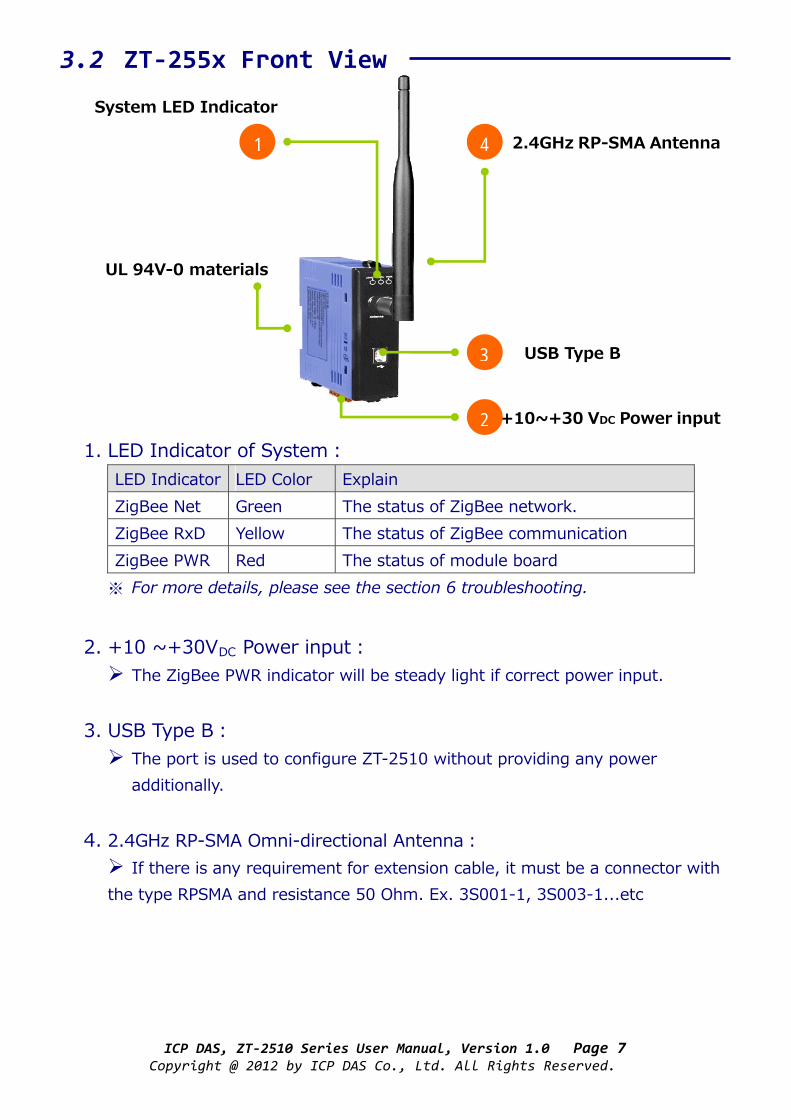
D. “RF Power” is the transmit power. Code Note 0x0F Typical Maximum 0x08 Fit the CE/FCC certification 0x00 Typical Minimum
※ The parameter adjustment purely personal behavior, ICP DAS can not guarantee to pass CE/FCC certification if adjusting this parameter, nor assume any liability because of the adjustment parameters derived from the RF Power.
4.2 Connecting the Power and Host PC 1. Connect the interface USB port for doing configuration.
CA‐0915
Windows Based PC
ICP DAS, ZT‐2510 Series User Manual, Version 1.0 Page 10 Copyright @ 2012 by ICP DAS Co., Ltd. All Rights Reserved.

4.3 Configuring ZigBee Setting 1. Launch the “ZT Configuration Utility” and click the [ZT Series] button.
2. Click the [Serial Port] icon and then select the COM Port number.
3. After selecting the COM Port number, a list of model numbers will be
displayed. Select the name of the module that you want to configure. After clicking the button, the utility will begin checking the connection.
2
1
3
ICP DAS, ZT‐2510 Series User Manual, Version 1.0 Page 11 Copyright @ 2012 by ICP DAS Co., Ltd. All Rights Reserved.
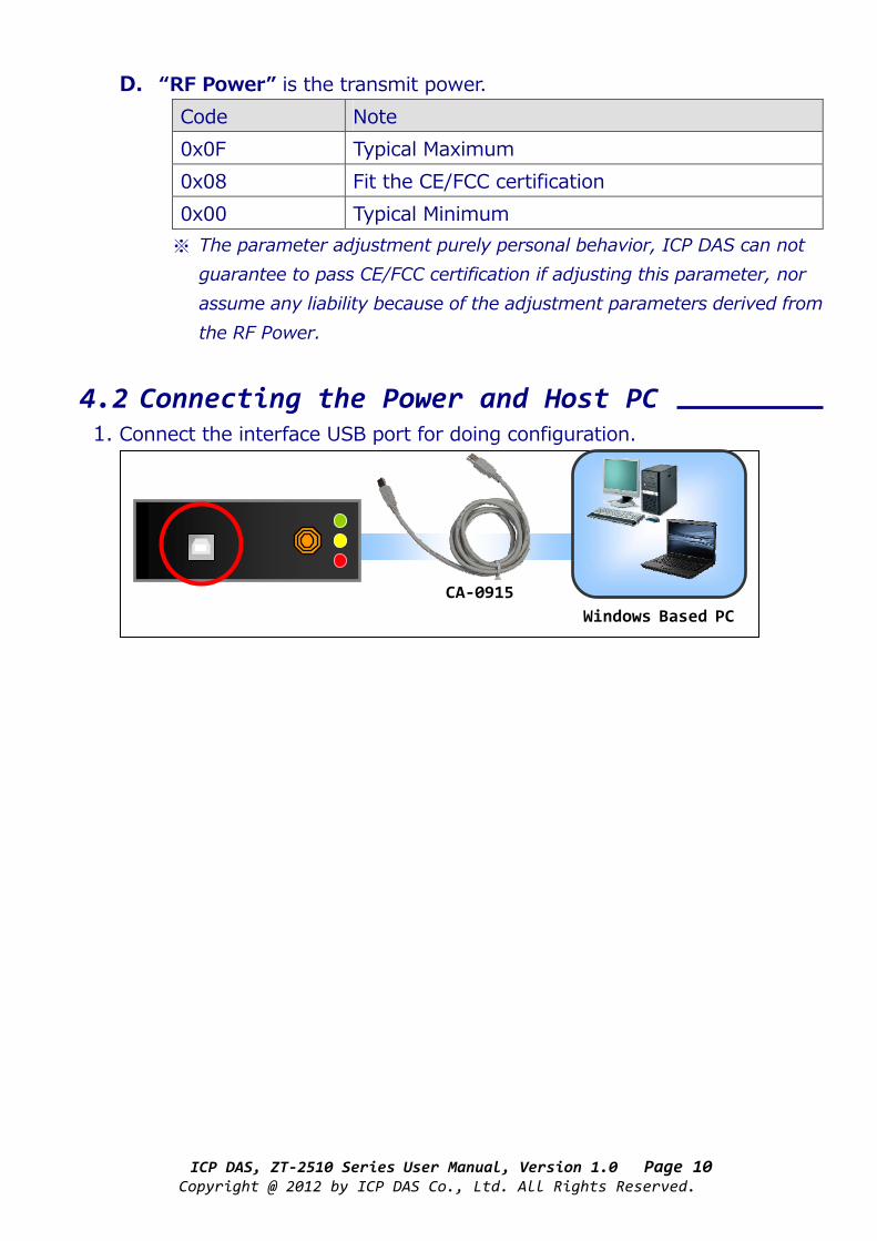
4. Once a connection is established, select either the [Default] or the [Wizard] function from the settings mode page.
5. Whether you select either the [Default] or the [Wizard] option for
performing configuration, both are used to configure the Pan ID, Node ID, RF Channel, RF Power and so the relevant parameters.
6. Once the module configuration has been completed, the message “The
Configuration was successful” will be displayed and it means the configuration has completed.
Default Wizard
4
ICP DAS, ZT‐2510 Series User Manual, Version 1.0 Page 12 Copyright @ 2012 by ICP DAS Co., Ltd. All Rights Reserved.

5 ZT‐2510 Applications (1) ZT-2510 is suitable used in which environment is many obstacles
and interferences.
HIGHVOLTAGE
WARNING
HIGHVOLTAGE
WARNING
[ZigBee Coordinator]
[ZigBee Router] [ZigBee End Device]
[ZigBee Coordinator]
[ZigBee Router] [ZigBee End Device]
ZT-2510
ICP DAS, ZT‐2510 Series User Manual, Version 1.0 Page 13 Copyright @ 2012 by ICP DAS Co., Ltd. All Rights Reserved.

(2) ZT-2510 is suitable used in which environment need to extend the communication range.
(3) ZT-2510 is suitable used as redundant routing path.
[ZigBee Coordinator]
[ZigBee Coordinator]
[ZigBee Router] [ZigBee End Device]
[ZigBee Router] [ZigBee End Device]
ZT-2510 ZT-2510
ICP DAS, ZT‐2510 Series User Manual, Version 1.0 Page 14 Copyright @ 2012 by ICP DAS Co., Ltd. All Rights Reserved.

6 Trouble shooting (1) LED Indicator Status: LED Indicator Status Introduction
The status of ZigBee network [ZigBee Router (Slave)] Steady Lit Signal Strength Blinking (500 ms) Signal Available Blinking (1s) Signal Weak
ZigBee Net (Green LED)
Blinking (2s) Signal Terrible or No ZigBee Network The status of ZigBee communication Blinking Receiving ZigBee data
ZigBee RxD (Yellow LED)
Steady Unlit No ZigBee data received The status of module board Steady Lit Power on
ZigBee PWR (Red LED)
Steady Unlit Power off
ICP DAS, ZT‐2510 Series User Manual, Version 1.0 Page 15 Copyright @ 2012 by ICP DAS Co., Ltd. All Rights Reserved.

(2) Technical Support. If you are any difficulties using the ZT-255x module, save the ZigBee configurations using the described below. Please also provide a description of problem and attach file to an email and send it to [email protected] 1. Set the DIP switch of the ZT-255x device to the [ZBSET] position
then reboot the device. Launch the ZT Configuration Utility and select [Save Log] icon to save the configuration of ZT-255x as a file.
2. After clicking the [Save Log] icon, enter the “File Name” and “File
Path” in the Windows save dialog. Once the configuration has been successfully saved, the following message will be displayed.
ICP DAS, ZT‐2510 Series User Manual, Version 1.0 Page 16 Copyright @ 2012 by ICP DAS Co., Ltd. All Rights Reserved.

7 Appendixes
Technology Support If there is any question or concerns for using ZT-2000 series module, please feel free to contact us:[email protected] If there is any question or concern for using ZT-2000 series module, please feel free to contact us. ICP DAS will reply you within three days at most as possible as we can. Taiwan Europe Website:http://www.icpads.com Website:http://www.icpdas-europe.com E-Mail:[email protected] E-mail:[email protected] TEL:886-3-597-3366 TEL:+49(0) 7121-143324-0 FAX:886-3-597-3733 FAX:+49(0) 7121-14324-90
China USA Website:http://www.icpdas.com.cn Website:http://www.icpdas-usa.com E-Mail:[email protected] E-Mail:mailto:[email protected] TEL:86-21-6247-1722 TEL:1-310-517-9888 x101 FAX:86-21-6247-1725 FAX:1-310-517-0998
ICP DAS, ZT‐2510 Series User Manual, Version 1.0 Page 17 Copyright @ 2012 by ICP DAS Co., Ltd. All Rights Reserved.


![ZigBee RF4CE Stack User Guide - NXP Semiconductors · 094945r00ZB ZigBee RF4CE Specification [ZigBee Alliance document] 094950r00ZB ZigBee RF4CE Device Type List [ZigBee Alliance](https://img.pdfslide.us/doc/110x75/5f168d2f412bb13bb1076764/zigbee-rf4ce-stack-user-guide-nxp-semiconductors-094945r00zb-zigbee-rf4ce-specification.jpg)