Embed Size (px)
Citation preview
SMS-531 Intelligent 3G Modbus SMS/Voice
Alarm Controller
User’s Manual V1.0
High Quality, Industrial Data Acquisition, and Control Products
SMS-531 User’s Manual v1.0
Warranty
All products manufactured by ICP DAS are warranted against defective
materials for a period of one year from the date of delivery to the original
purchaser.
Warning
ICP DAS assumes no liability for damages consequent to the use of this
product. ICP DAS reserves the right to change this manual at any time
without notice. The information furnished by ICP DAS is believed to be
accurate and reliable. However, no responsibility is assumed by ICP DAS
for its use, or for any infringements of patents or other rights of third
parties resulting from its use.
Copyright
Copyright 2012 by ICP DAS CO., LTD. All rights reserved worldwide.
Trademark
The names used for identification only may be registered trademarks of
their respective companies.
Version Date Author Description
1.0 2013/01/24 William Release version
SMS-531 User’s Manual v1.0
I
Table of Contents
1. Introduction ............................................................................................. 1
1.1 Features ............................................................................................................... 2
1.2 Applications ........................................................................................................ 2
2. Hardware ................................................................................................. 4
2.1 Specifications ..................................................................................................... 4
2.2 Appearance and Pin Assignments ....................................................................... 5
2.3 Dimensions ......................................................................................................... 6
2.4 LED Indicators ................................................................................................... 7
2.5 Installing the SMS-531 ....................................................................................... 8
3. Installing the GT-531 Series Utility ....................................................... 9
3.1 Installing .NET Compact Framework ................................................................ 9
3.2 Installing GT-531 Series Utility......................................................................... 11
4. The GT-531 Series Utility Operation Description .............................. 14
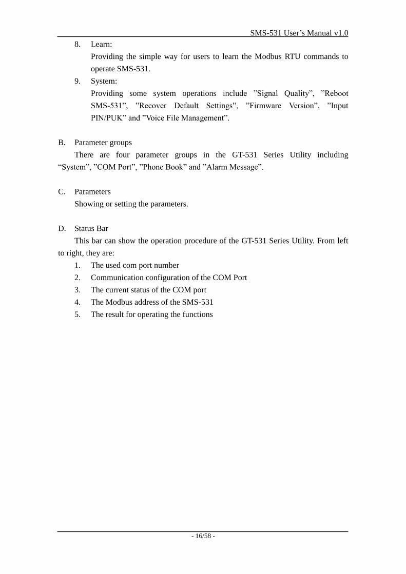
4.1 Main Menu ....................................................................................................... 15
4.2 File Menu .......................................................................................................... 17
4.3 Connecting to the SMS-531 ............................................................................. 17
4.4 Parameters ........................................................................................................ 18
4.4.1 System ................................................................................................... 18
4.4.2 COM Port .............................................................................................. 20
4.4.3 Phone Book ........................................................................................... 20
4.4.4 Alarm Message ...................................................................................... 22
4.5 Downloading/Uploading the SMS-531’s Parameters ....................................... 23
4.6 Learning Modbus RTU Commands and Testing .............................................. 24
4.7 System .............................................................................................................. 26
4.7.1 Signal Quality ........................................................................................ 26
4.7.2 Inquiring Firmware Version ................................................................... 27
4.7.3 Inputting the PIN/PUK Code ................................................................. 28
4.7.4 Voice File Management ......................................................................... 29
4.7.5 Reset the SMS-531 ................................................................................ 30
4.7.6 Recover to the Factory Settings ............................................................. 30
4.8 Language .......................................................................................................... 31
4.9 Exit ................................................................................................................... 31
5. Example .................................................................................................. 32
5.1 Example 1: Sending the general alarm SMS (Level Trigger) .......................... 33
5.2 Example 2: Sending the variable alarm SMS ................................................... 37
5.3 Example 3: Sending the alarm SMS dynamically ............................................ 41
5.4 Example 4: Sending the alarm voice ................................................................ 44
SMS-531 User’s Manual v1.0
II
5.5 Example 5: Receiving the SMS ........................................................................ 47
5.6 Example 6: Sending the general alarm SMS (Edge Trigger) ........................... 51
6. SMS-531 Modbus Address Table ......................................................... 55
7. Troubleshooting ..................................................................................... 58
SMS-531 User’s Manual v1.0
- 1/58 -
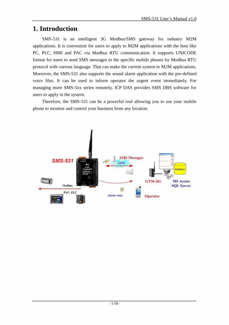
1. Introduction
SMS-531 is an intelligent 3G Modbus/SMS gateway for industry M2M
applications. It is convenient for users to apply to M2M applications with the host like
PC, PLC, HMI and PAC via Modbus RTU communication. It supports UNICODE
format for users to send SMS messages to the specific mobile phones by Modbus RTU
protocol with various language. That can make the current system to M2M applications.
Moreover, the SMS-531 also supports the sound alarm application with the pre-defined
voice files. It can be used to inform operator the urgent event immediately. For
managing more SMS-5xx series remotely, ICP DAS provides SMS DBS software for
users to apply in the system.
Therefore, the SMS-531 can be a powerful tool allowing you to use your mobile
phone to monitor and control your business from any location.
SMS-531 User’s Manual v1.0
- 2/58 -
1.1 Features
Support GSM 850/900/1800/1900 MHz Quad-band frequency
Support WCDMA 850/900/1900/2100 MHz Quad-band frequency
Support Modbus RTU slave protocol
Support max. 256 short messages and voice alarms
Support max. 70 Unicode Characters
Easy to setup and configure
Escalation and reminder function
Up to 256 mobile phones can be alerted for each alarm point
These phone numbers can be divided into groups
Configurable SMS messages
The content of sending SMS message can be changed by Modbus protocol
Built-in Watchdog Function
Industrial Design with Surge Protection
Support SMS DB of ICP DAS software
1 RS-485, 2 RS-232 port
Support micro SD/SDHC card. (max. 32G bytes)
Support DC +10 VDC ~ +30 VDC Power Input
DIN Rail design
1.2 Applications
Remote equipment maintenance and automation
Vending or Gaming monitor system
Home/Factory security
Escalators & Elevators
Energy Management
Temperature Monitoring
SMS-531 User’s Manual v1.0
- 3/58 -
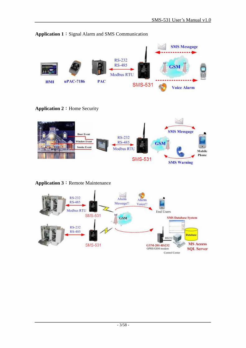
Application 1:Signal Alarm and SMS Communication
Application 2:Home Security
Application 3:Remote Maintenance
SMS-531 User’s Manual v1.0
- 4/58 -
2. Hardware
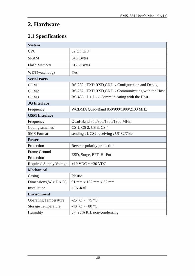
2.1 Specifications
System
CPU 32 bit CPU
SRAM 64K Bytes
Flash Memory 512K Bytes
WDT(watchdog) Yes
Serial Ports
COM1 RS-232 : TXD,RXD,GND:Configuration and Debug
COM2 RS-232 : TXD,RXD,GND:Communicating with the Host
COM3 RS-485 : D+,D-:Communicating with the Host
3G Interface
Frequency WCDMA Quad-Band 850/900/1900/2100 MHz
GSM Interface
Frequency Quad-Band 850/900/1800/1900 MHz
Coding schemes CS 1, CS 2, CS 3, CS 4
SMS Format sending : UCS2 receiving : UCS2/7bits
Power
Protection Reverse polarity protection
Frame Ground
Protection ESD, Surge, EFT, Hi-Pot
Required Supply Voltage +10 VDC ~ +30 VDC
Mechanical
Casing Plastic
Dimensions(W x H x D) 91 mm x 132 mm x 52 mm
Installation DIN-Rail
Environment
Operating Temperature -25 °C ~ +75 °C
Storage Temperature -40 °C ~ +80 °C
Humidity 5 ~ 95% RH, non-condensing
SMS-531 User’s Manual v1.0
- 5/58 -
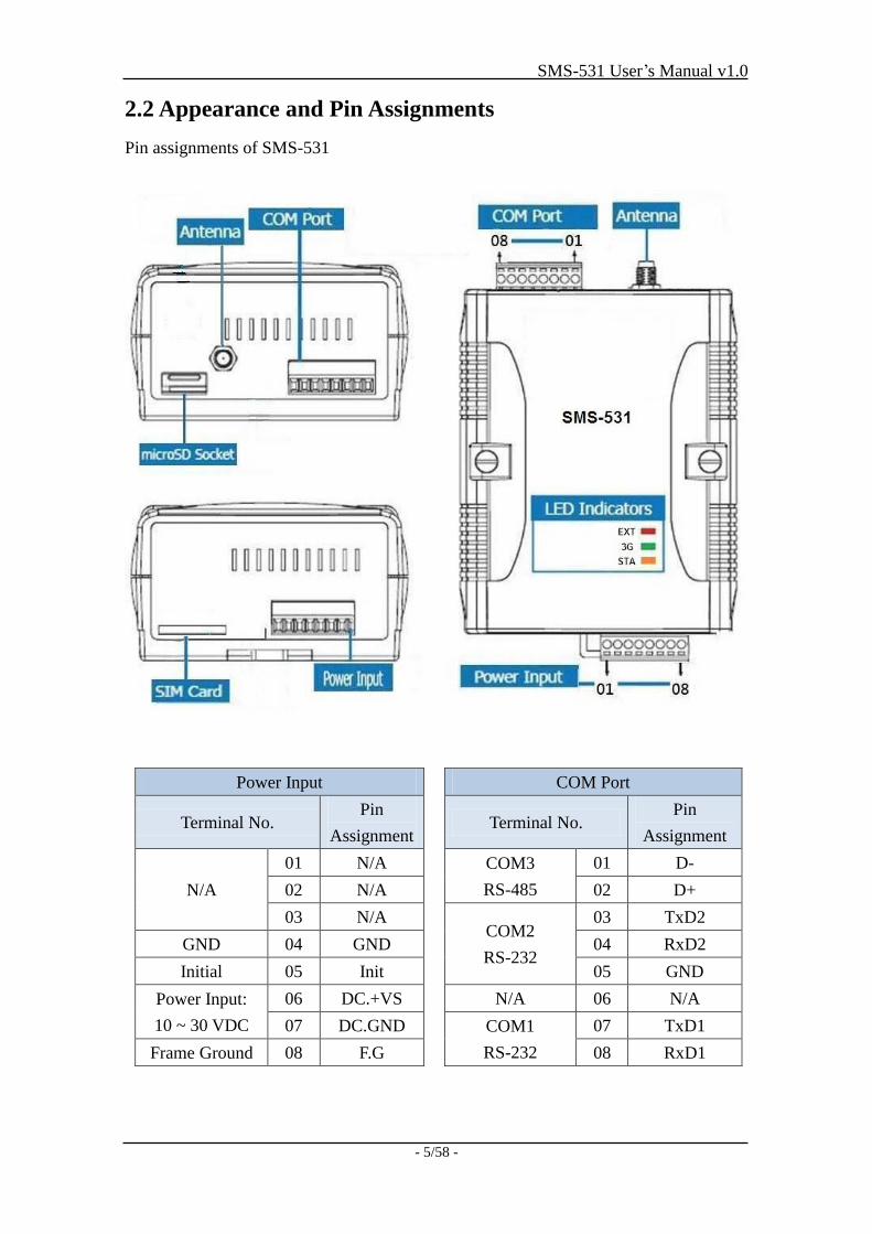
2.2 Appearance and Pin Assignments
Pin assignments of SMS-531
Power Input
Terminal No. Pin
Assignment
N/A
01 N/A
02 N/A
03 N/A
GND 04 GND
Initial 05 Init
Power Input:
10 ~ 30 VDC
06 DC.+VS
07 DC.GND
Frame Ground 08 F.G
COM Port
Terminal No. Pin
Assignment
COM3
RS-485
01 D-
02 D+
COM2
RS-232
03 TxD2
04 RxD2
05 GND
N/A 06 N/A
COM1
RS-232
07 TxD1
08 RxD1
SMS-531 User’s Manual v1.0
- 6/58 -
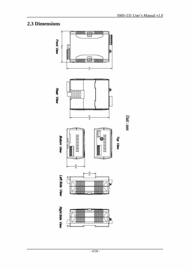
2.3 Dimensions
SMS-531 User’s Manual v1.0
- 7/58 -
2.4 LED Indicators
There are three LED indicators to help users to judge the various conditions in the
SMS-531. The description is as follows:
A. EXT (Red): The External Power LED is to indicate whether the power is
supplied or not.
The power is active The power is not active
On Off
B. 3G (Green): The modem LED can indicate the status of 3G module. (After
modem registered)
(1) Use 3G SIM card.
3G module normal 3G module fail
Blanking*2 (2 sec) Off or Blanking (not 2 sec)
(2) Use 2G SIM card.
3G module normal 3G module fail
Blanking*1 (2 sec) Off or Blanking (not 2 sec)
Note: When the SMS-531 sends voice alarm, the 3G LED is continuous on.
C. STA (Orange): The System LED is to indicate if the SMS-531 is normal or
fail.
Normal(idle) Running 3G error Wrong PIN/PUK code
Blanking (1 sec) Blanking (0.5 sec) Always on or off Blinking per 50 ms
SMS-531 User’s Manual v1.0
- 8/58 -
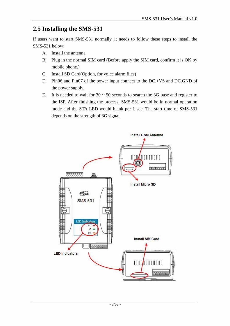
2.5 Installing the SMS-531
If users want to start SMS-531 normally, it needs to follow these steps to install the
SMS-531 below:
A. Install the antenna
B. Plug in the normal SIM card (Before apply the SIM card, confirm it is OK by
mobile phone.)
C. Install SD Card(Option, for voice alarm files)
D. Pin06 and Pin07 of the power input connect to the DC.+VS and DC.GND of
the power supply.
E. It is needed to wait for 30 ~ 50 seconds to search the 3G base and register to
the ISP. After finishing the process, SMS-531 would be in normal operation
mode and the STA LED would blank per 1 sec. The start time of SMS-531
depends on the strength of 3G signal.
SMS-531 User’s Manual v1.0
- 9/58 -
3. Installing the GT-531 Series Utility
It needs the runtime environment with .NET Framework 2.0 or above to execute
the GT-531 Series Utility in the PC. If there has .NET Framework 2.0 or above in the
PC, the section 3.1 can be omitted.
3.1 Installing .NET Compact Framework
The user can download the .NET Compact Framework 2.0 or above from
Microsoft web site. The install figure is as follows:
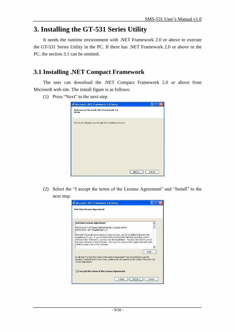
(1) Press “Next” to the next step.
(2) Select the “I accept the terms of the License Agreement” and “Install” to the
next step.
SMS-531 User’s Manual v1.0
- 10/58 -
(3) The installation process would be going.
(4) After finishing the installation, press “Finish” to exit the program.
SMS-531 User’s Manual v1.0
- 11/58 -
3.2 Installing GT-531 Series Utility
A. Plug in the shipment CD into the PC
B. Execute \software\pc_utility\Install_GT531_Series_Utility_Vxxx.exe
The installation figure is as follows:
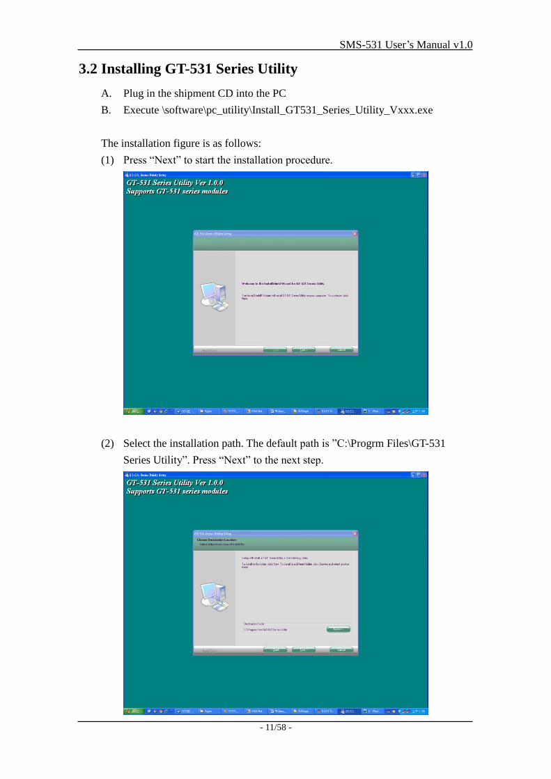
(1) Press “Next” to start the installation procedure.
(2) Select the installation path. The default path is ”C:\Progrm Files\GT-531
Series Utility”. Press “Next” to the next step.
SMS-531 User’s Manual v1.0
- 12/58 -
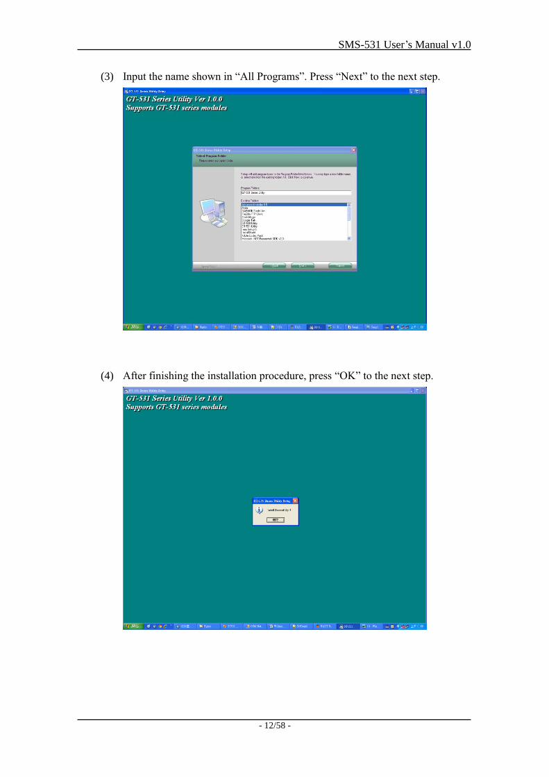
(3) Input the name shown in “All Programs”. Press “Next” to the next step.
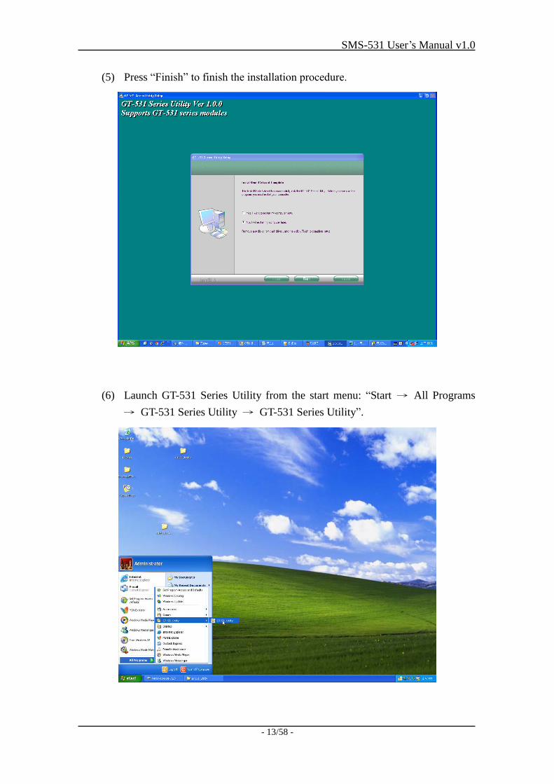
(4) After finishing the installation procedure, press “OK” to the next step.
SMS-531 User’s Manual v1.0
- 13/58 -
(5) Press “Finish” to finish the installation procedure.
(6) Launch GT-531 Series Utility from the start menu: “Start → All Programs
→ GT-531 Series Utility → GT-531 Series Utility”.
SMS-531 User’s Manual v1.0
- 14/58 -
4. The GT-531 Series Utility Operation Description
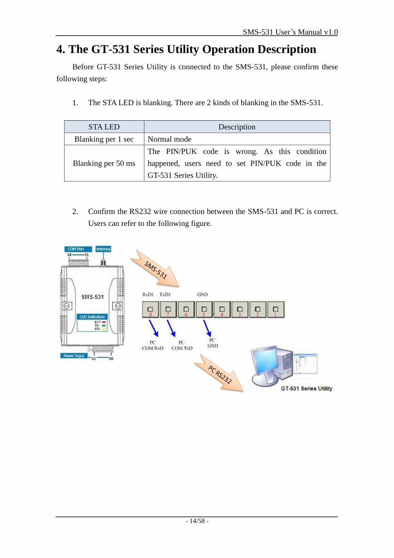
Before GT-531 Series Utility is connected to the SMS-531, please confirm these
following steps:
1. The STA LED is blanking. There are 2 kinds of blanking in the SMS-531.
STA LED Description
Blanking per 1 sec Normal mode
Blanking per 50 ms
The PIN/PUK code is wrong. As this condition
happened, users need to set PIN/PUK code in the
GT-531 Series Utility.
2. Confirm the RS232 wire connection between the SMS-531 and PC is correct.
Users can refer to the following figure.
SMS-531 User’s Manual v1.0
- 15/58 -
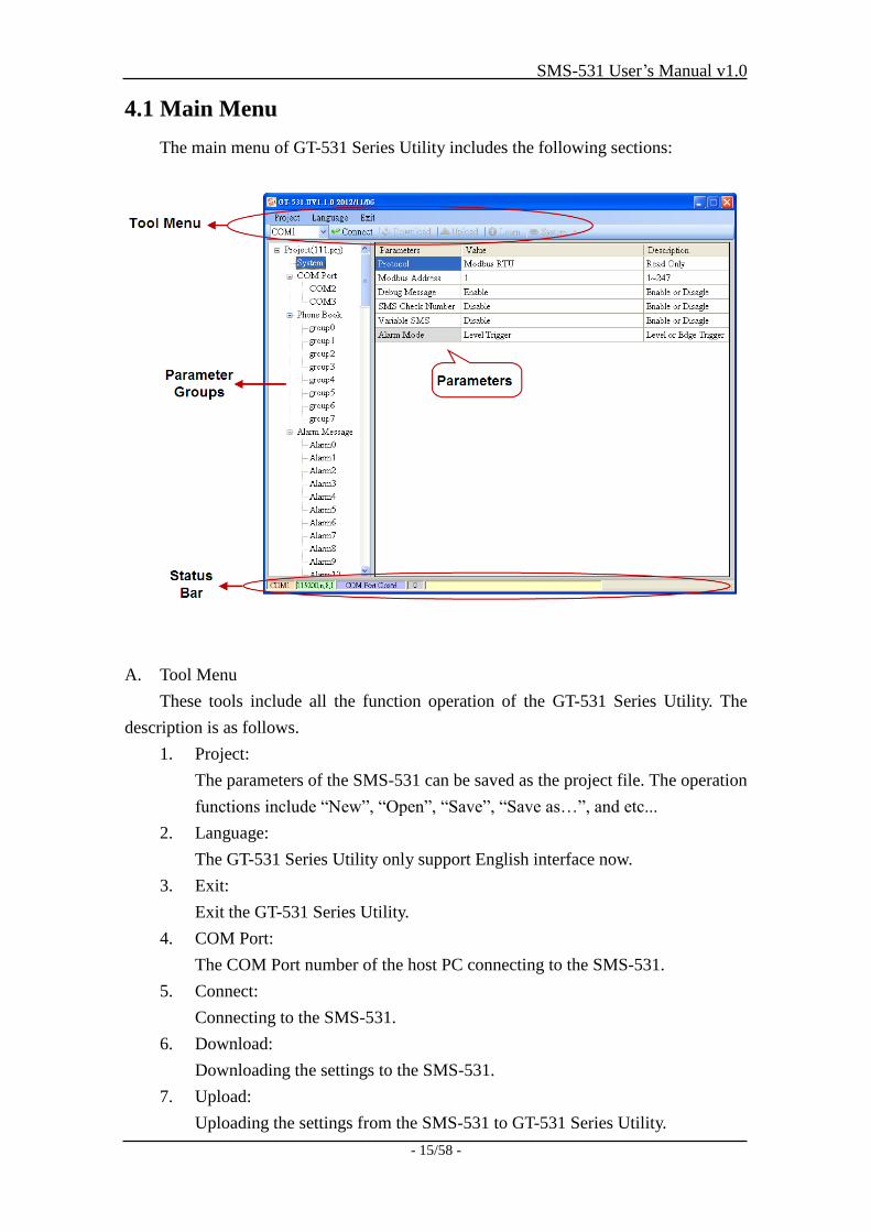
4.1 Main Menu
The main menu of GT-531 Series Utility includes the following sections:
A. Tool Menu
These tools include all the function operation of the GT-531 Series Utility. The
description is as follows.
1. Project:
The parameters of the SMS-531 can be saved as the project file. The operation
functions include “New”, “Open”, “Save”, “Save as…”, and etc...
2. Language:
The GT-531 Series Utility only support English interface now.
3. Exit:
Exit the GT-531 Series Utility.
4. COM Port:
The COM Port number of the host PC connecting to the SMS-531.
5. Connect:
Connecting to the SMS-531.
6. Download:
Downloading the settings to the SMS-531.
7. Upload:
Uploading the settings from the SMS-531 to GT-531 Series Utility.
SMS-531 User’s Manual v1.0
- 16/58 -
8. Learn:
Providing the simple way for users to learn the Modbus RTU commands to
operate SMS-531.
9. System:
Providing some system operations include ”Signal Quality”, ”Reboot
SMS-531”, ”Recover Default Settings”, ”Firmware Version”, ”Input
PIN/PUK” and ”Voice File Management”.
B. Parameter groups
There are four parameter groups in the GT-531 Series Utility including
“System”, ”COM Port”, ”Phone Book” and ”Alarm Message”.
C. Parameters
Showing or setting the parameters.
D. Status Bar
This bar can show the operation procedure of the GT-531 Series Utility. From left
to right, they are:
1. The used com port number
2. Communication configuration of the COM Port
3. The current status of the COM port
4. The Modbus address of the SMS-531
5. The result for operating the functions
SMS-531 User’s Manual v1.0
- 17/58 -
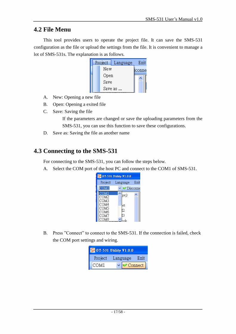
4.2 File Menu
This tool provides users to operate the project file. It can save the SMS-531
configuration as the file or upload the settings from the file. It is convenient to manage a
lot of SMS-531s. The explanation is as follows.
A. New: Opening a new file
B. Open: Opening a exited file
C. Save: Saving the file
If the parameters are changed or save the uploading parameters from the
SMS-531, you can use this function to save these configurations.
D. Save as: Saving the file as another name
4.3 Connecting to the SMS-531
For connecting to the SMS-531, you can follow the steps below.
A. Select the COM port of the host PC and connect to the COM1 of SMS-531.
B. Press ”Connect” to connect to the SMS-531. If the connection is failed, check
the COM port settings and wiring.
SMS-531 User’s Manual v1.0
- 18/58 -
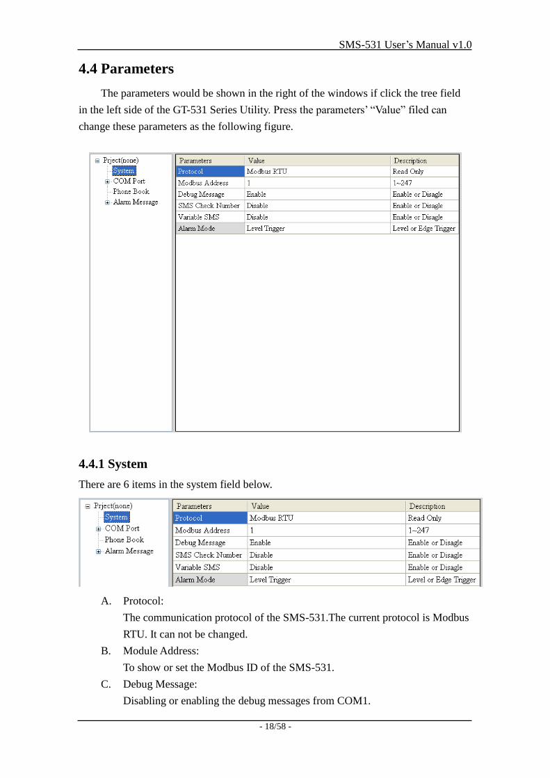
4.4 Parameters
The parameters would be shown in the right of the windows if click the tree field
in the left side of the GT-531 Series Utility. Press the parameters’ “Value” filed can
change these parameters as the following figure.
4.4.1 System
There are 6 items in the system field below.
A. Protocol:
The communication protocol of the SMS-531.The current protocol is Modbus
RTU. It can not be changed.
B. Module Address:
To show or set the Modbus ID of the SMS-531.
C. Debug Message:
Disabling or enabling the debug messages from COM1.
SMS-531 User’s Manual v1.0
- 19/58 -
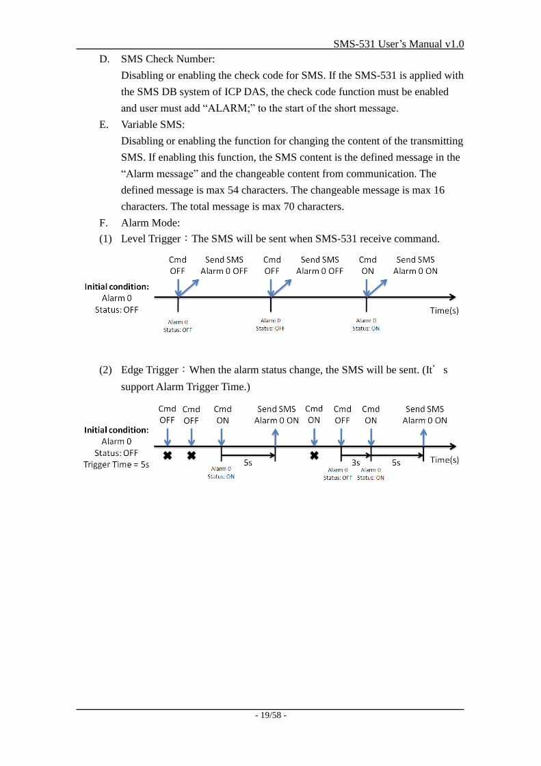
D. SMS Check Number:
Disabling or enabling the check code for SMS. If the SMS-531 is applied with
the SMS DB system of ICP DAS, the check code function must be enabled
and user must add “ALARM;” to the start of the short message.
E. Variable SMS:
Disabling or enabling the function for changing the content of the transmitting
SMS. If enabling this function, the SMS content is the defined message in the
“Alarm message” and the changeable content from communication. The
defined message is max 54 characters. The changeable message is max 16
characters. The total message is max 70 characters.
F. Alarm Mode:
(1) Level Trigger:The SMS will be sent when SMS-531 receive command.
(2) Edge Trigger:When the alarm status change, the SMS will be sent. (It’s
support Alarm Trigger Time.)
SMS-531 User’s Manual v1.0
- 20/58 -
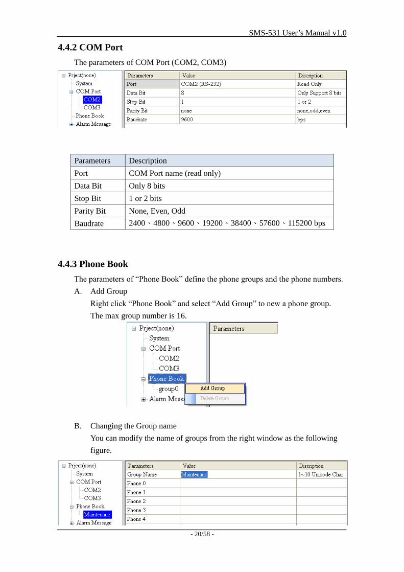
4.4.2 COM Port
The parameters of COM Port (COM2, COM3)
Parameters Description
Port COM Port name (read only)
Data Bit Only 8 bits
Stop Bit 1 or 2 bits
Parity Bit None, Even, Odd
Baudrate 2400、4800、9600、19200、38400、57600、115200 bps
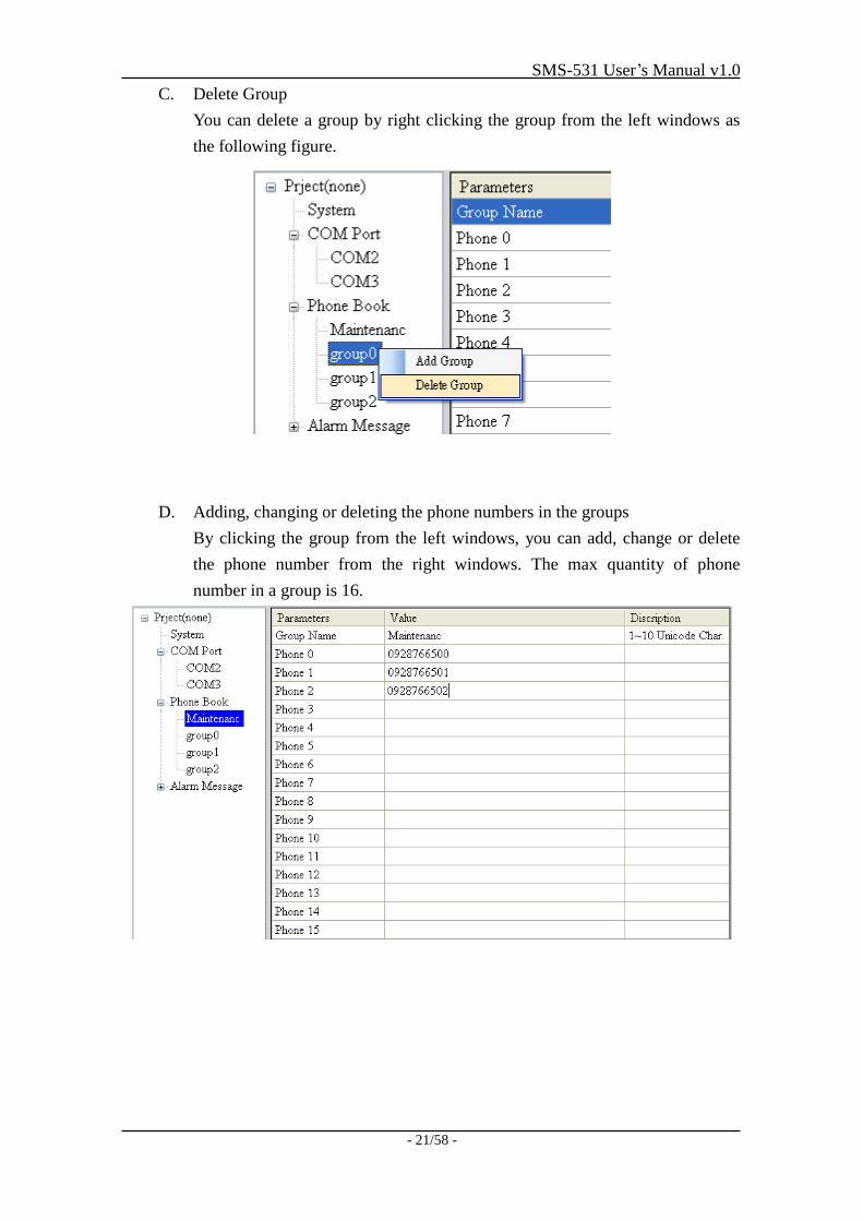
4.4.3 Phone Book
The parameters of “Phone Book” define the phone groups and the phone numbers.
A. Add Group
Right click “Phone Book” and select “Add Group” to new a phone group.
The max group number is 16.
B. Changing the Group name
You can modify the name of groups from the right window as the following
figure.
SMS-531 User’s Manual v1.0
- 21/58 -
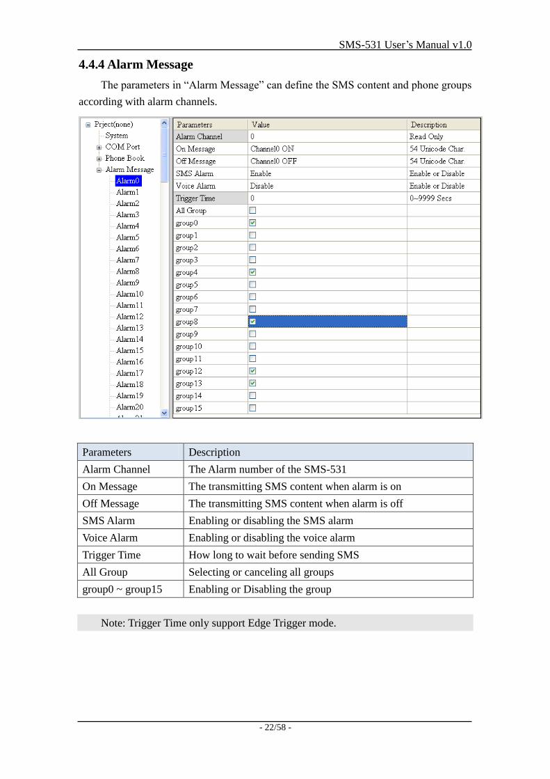
C. Delete Group
You can delete a group by right clicking the group from the left windows as
the following figure.
D. Adding, changing or deleting the phone numbers in the groups
By clicking the group from the left windows, you can add, change or delete
the phone number from the right windows. The max quantity of phone
number in a group is 16.
SMS-531 User’s Manual v1.0
- 22/58 -
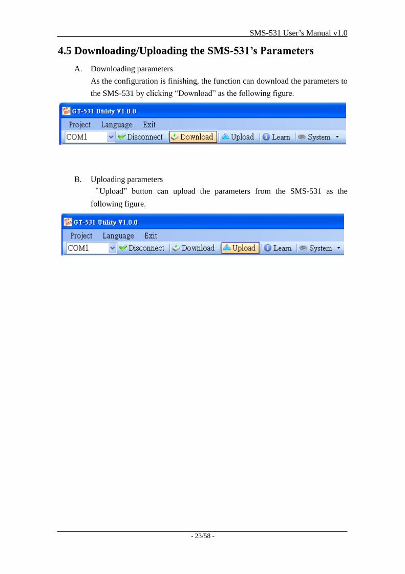
4.4.4 Alarm Message
The parameters in “Alarm Message” can define the SMS content and phone groups
according with alarm channels.
Parameters Description
Alarm Channel The Alarm number of the SMS-531
On Message The transmitting SMS content when alarm is on
Off Message The transmitting SMS content when alarm is off
SMS Alarm Enabling or disabling the SMS alarm
Voice Alarm Enabling or disabling the voice alarm
Trigger Time How long to wait before sending SMS
All Group Selecting or canceling all groups
group0 ~ group15 Enabling or Disabling the group
Note: Trigger Time only support Edge Trigger mode.
SMS-531 User’s Manual v1.0
- 23/58 -
4.5 Downloading/Uploading the SMS-531’s Parameters
A. Downloading parameters
As the configuration is finishing, the function can download the parameters to
the SMS-531 by clicking “Download” as the following figure.
B. Uploading parameters
“Upload” button can upload the parameters from the SMS-531 as the
following figure.
SMS-531 User’s Manual v1.0
- 24/58 -
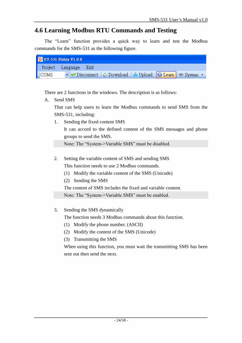
4.6 Learning Modbus RTU Commands and Testing
The “Learn” function provides a quick way to learn and test the Modbus
commands for the SMS-531 as the following figure.
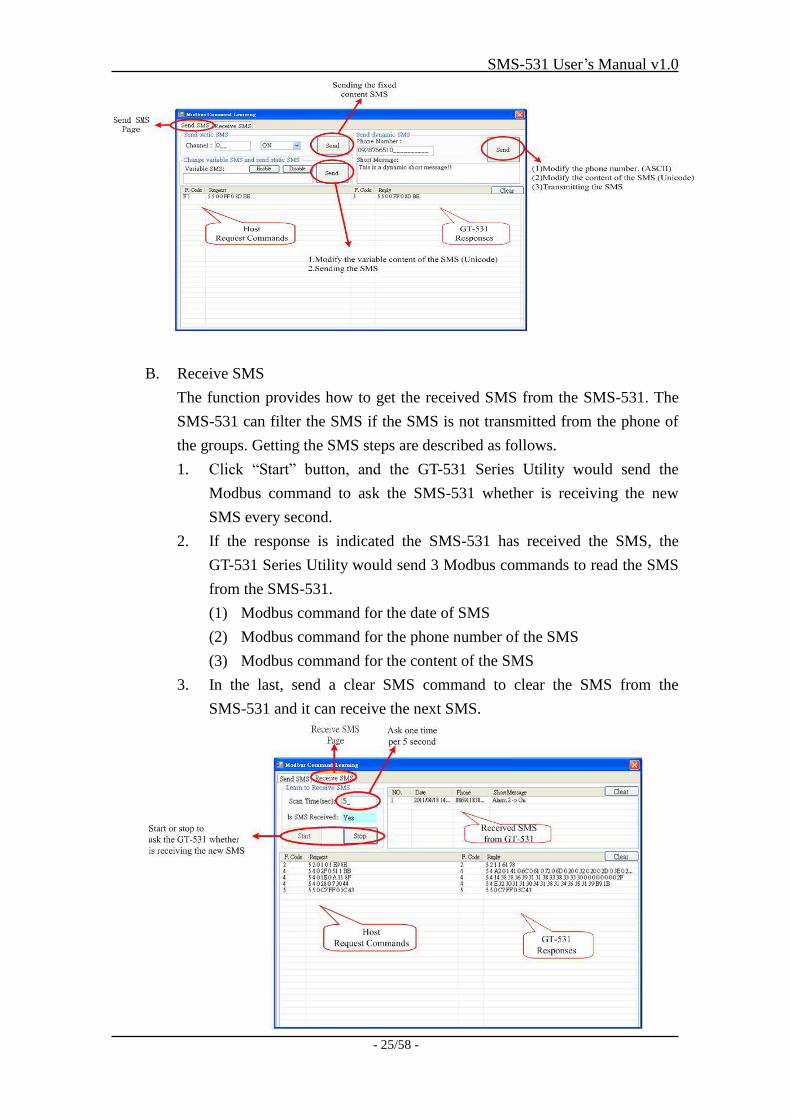
There are 2 functions in the windows. The description is as follows:
A. Send SMS
That can help users to learn the Modbus commands to send SMS from the
SMS-531, including:
1. Sending the fixed content SMS
It can accord to the defined content of the SMS messages and phone
groups to send the SMS.
Note: The “System->Variable SMS” must be disabled.
2. Setting the variable content of SMS and sending SMS
This function needs to use 2 Modbus commands.
(1) Modify the variable content of the SMS (Unicode)
(2) Sending the SMS
The content of SMS includes the fixed and variable content.
Note: The “System->Variable SMS” must be enabled.
3. Sending the SMS dynamically
The function needs 3 Modbus commands about this function.
(1) Modify the phone number. (ASCII)
(2) Modify the content of the SMS (Unicode)
(3) Transmitting the SMS
When using this function, you must wait the transmitting SMS has been
sent out then send the next.
SMS-531 User’s Manual v1.0
- 25/58 -
B. Receive SMS
The function provides how to get the received SMS from the SMS-531. The
SMS-531 can filter the SMS if the SMS is not transmitted from the phone of
the groups. Getting the SMS steps are described as follows.
1. Click “Start” button, and the GT-531 Series Utility would send the
Modbus command to ask the SMS-531 whether is receiving the new
SMS every second.
2. If the response is indicated the SMS-531 has received the SMS, the
GT-531 Series Utility would send 3 Modbus commands to read the SMS
from the SMS-531.
(1) Modbus command for the date of SMS
(2) Modbus command for the phone number of the SMS
(3) Modbus command for the content of the SMS
3. In the last, send a clear SMS command to clear the SMS from the
SMS-531 and it can receive the next SMS.
SMS-531 User’s Manual v1.0
- 26/58 -
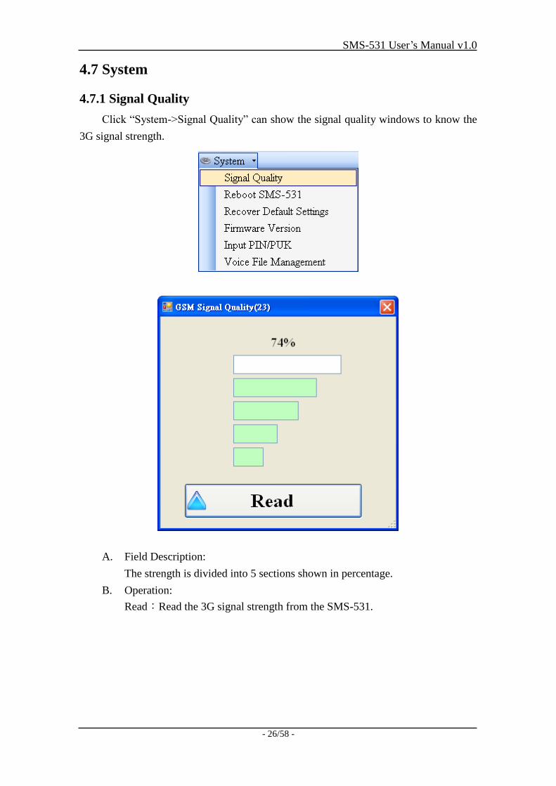
4.7 System
4.7.1 Signal Quality
Click “System->Signal Quality” can show the signal quality windows to know the
3G signal strength.
A. Field Description:
The strength is divided into 5 sections shown in percentage.
B. Operation:
Read:Read the 3G signal strength from the SMS-531.
SMS-531 User’s Manual v1.0
- 27/58 -
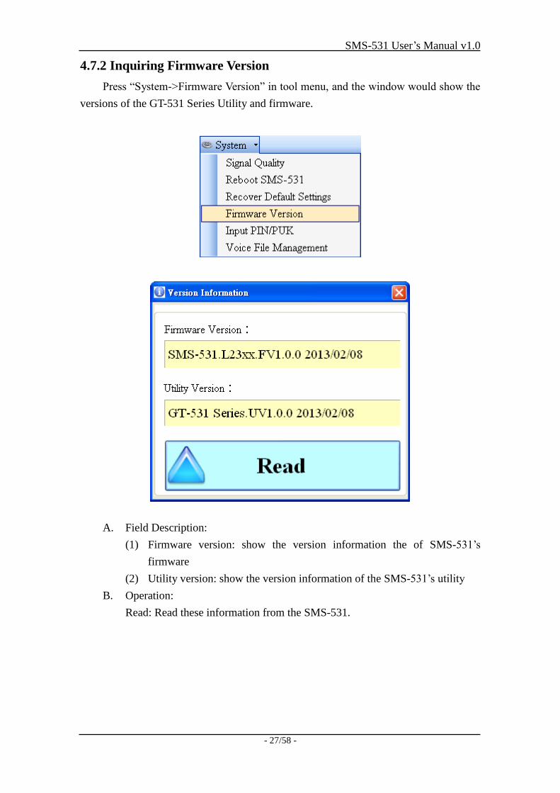
4.7.2 Inquiring Firmware Version
Press “System->Firmware Version” in tool menu, and the window would show the
versions of the GT-531 Series Utility and firmware.
A. Field Description:
(1) Firmware version: show the version information the of SMS-531’s
firmware
(2) Utility version: show the version information of the SMS-531’s utility
B. Operation:
Read: Read these information from the SMS-531.
SMS-531 User’s Manual v1.0
- 28/58 -
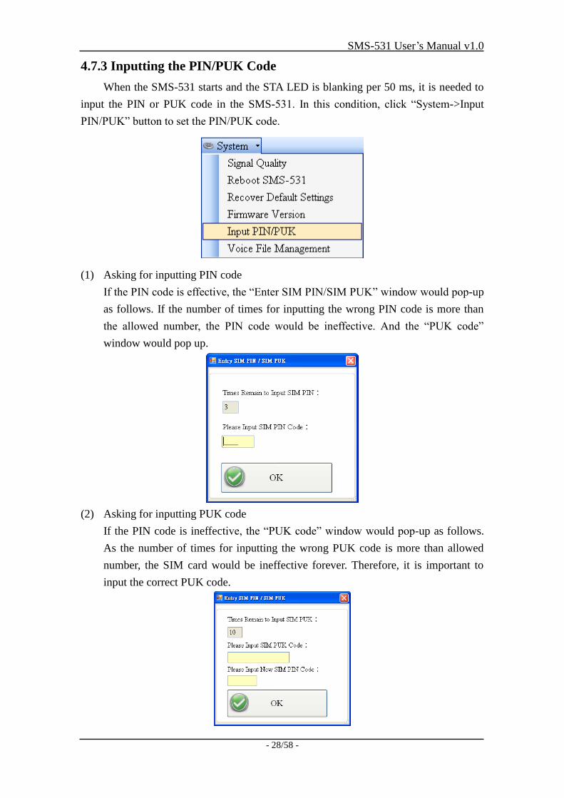
4.7.3 Inputting the PIN/PUK Code
When the SMS-531 starts and the STA LED is blanking per 50 ms, it is needed to
input the PIN or PUK code in the SMS-531. In this condition, click “System->Input
PIN/PUK” button to set the PIN/PUK code.
(1) Asking for inputting PIN code
If the PIN code is effective, the “Enter SIM PIN/SIM PUK” window would pop-up
as follows. If the number of times for inputting the wrong PIN code is more than
the allowed number, the PIN code would be ineffective. And the “PUK code”
window would pop up.
(2) Asking for inputting PUK code
If the PIN code is ineffective, the “PUK code” window would pop-up as follows.
As the number of times for inputting the wrong PUK code is more than allowed
number, the SIM card would be ineffective forever. Therefore, it is important to
input the correct PUK code.
SMS-531 User’s Manual v1.0
- 29/58 -
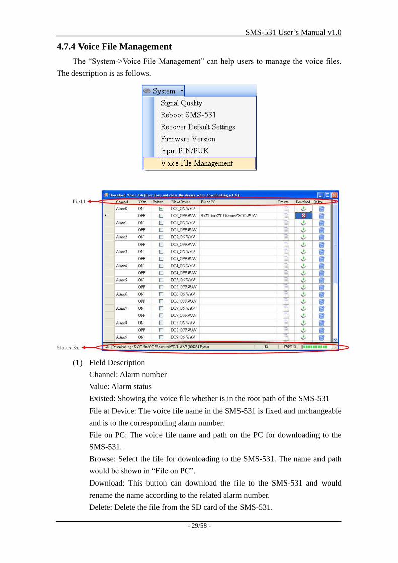
4.7.4 Voice File Management
The “System->Voice File Management” can help users to manage the voice files.
The description is as follows.
(1) Field Description
Channel: Alarm number
Value: Alarm status
Existed: Showing the voice file whether is in the root path of the SMS-531
File at Device: The voice file name in the SMS-531 is fixed and unchangeable
and is to the corresponding alarm number.
File on PC: The voice file name and path on the PC for downloading to the
SMS-531.
Browse: Select the file for downloading to the SMS-531. The name and path
would be shown in “File on PC”.
Download: This button can download the file to the SMS-531 and would
rename the name according to the related alarm number.
Delete: Delete the file from the SD card of the SMS-531.
SMS-531 User’s Manual v1.0
- 30/58 -
(2) Status Bar
The status bar shows the SD status and the downloading information. The
information is as follows from left to right.
1. The SD status: OK: Normal, NO: SD card error.
2. The voice file path, name and size
3. The current downloading time
4. The block number of the file and the transmitted block
5. The percent of downloading
Note: Due to the downloading file of the Utility is using COM port, the
downloading speed is not fast. If the file size is over 1 Mbytes, we recommend users to
copy and rename the file by SD card reader.
(3) Sound Format
SMS-531 only support WAV file and the following file format needed:
File type *.Wav
Audio type PCM
Data bit 16 bits
Channel Single track
Sample rate 8 kHz,11 kHz
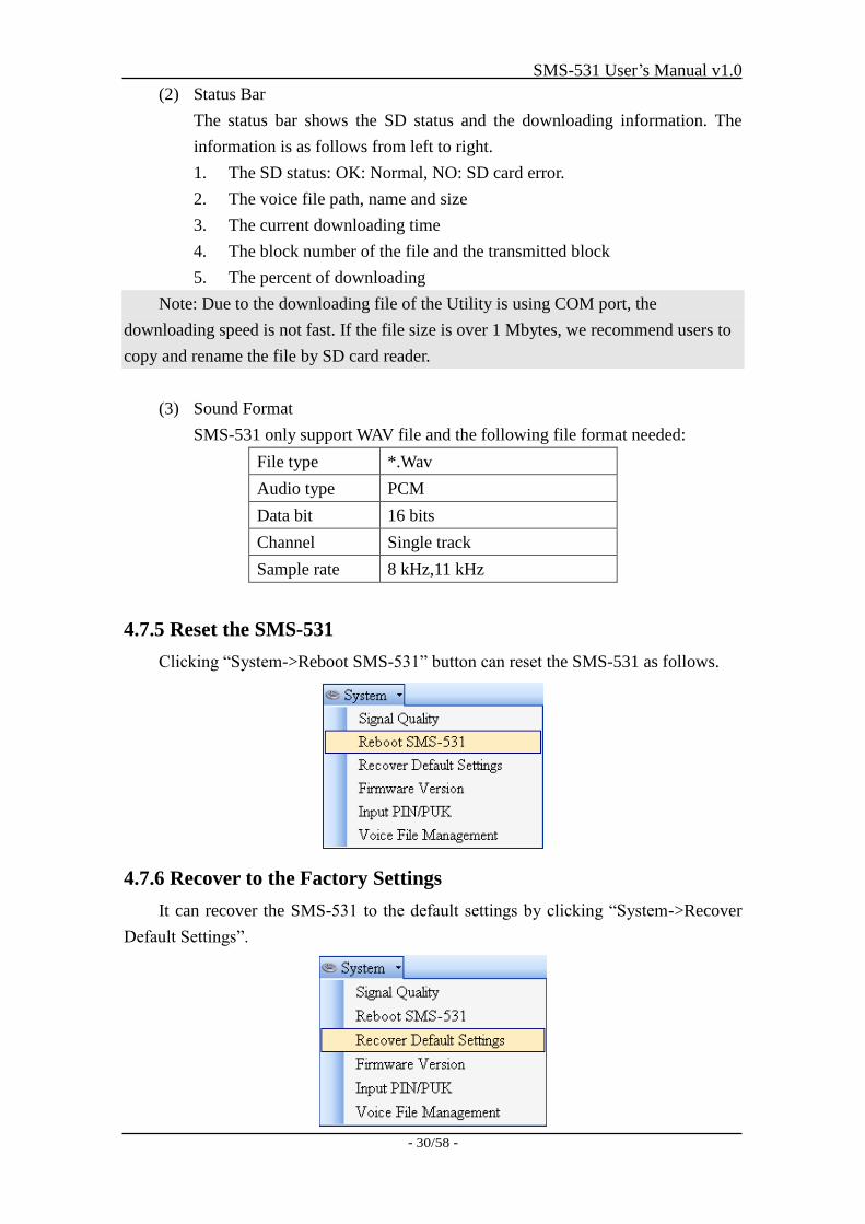
4.7.5 Reset the SMS-531
Clicking “System->Reboot SMS-531” button can reset the SMS-531 as follows.
4.7.6 Recover to the Factory Settings
It can recover the SMS-531 to the default settings by clicking “System->Recover
Default Settings”.
SMS-531 User’s Manual v1.0
- 31/58 -
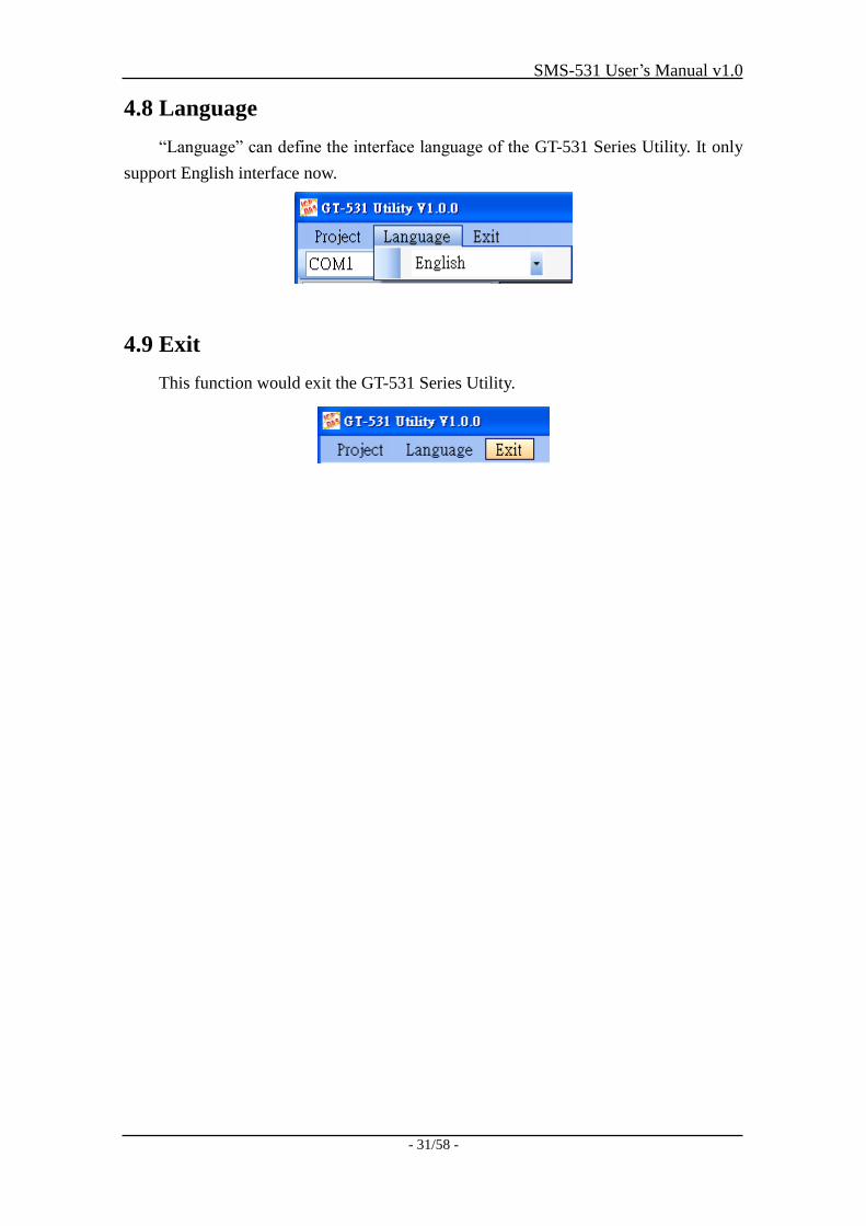
4.8 Language
“Language” can define the interface language of the GT-531 Series Utility. It only
support English interface now.
4.9 Exit
This function would exit the GT-531 Series Utility.
SMS-531 User’s Manual v1.0
- 32/58 -
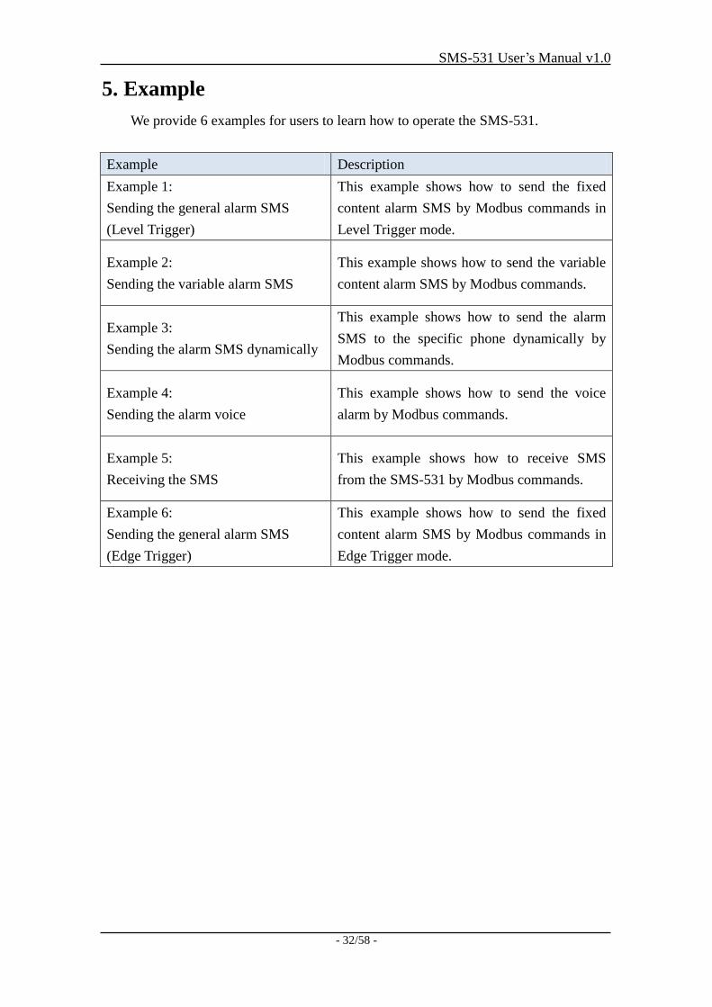
5. Example
We provide 6 examples for users to learn how to operate the SMS-531.
Example Description
Example 1:
Sending the general alarm SMS
(Level Trigger)
This example shows how to send the fixed
content alarm SMS by Modbus commands in
Level Trigger mode.
Example 2:
Sending the variable alarm SMS
This example shows how to send the variable
content alarm SMS by Modbus commands.
Example 3:
Sending the alarm SMS dynamically
This example shows how to send the alarm
SMS to the specific phone dynamically by
Modbus commands.
Example 4:
Sending the alarm voice
This example shows how to send the voice
alarm by Modbus commands.
Example 5:
Receiving the SMS
This example shows how to receive SMS
from the SMS-531 by Modbus commands.
Example 6:
Sending the general alarm SMS
(Edge Trigger)
This example shows how to send the fixed
content alarm SMS by Modbus commands in
Edge Trigger mode.
SMS-531 User’s Manual v1.0
- 33/58 -
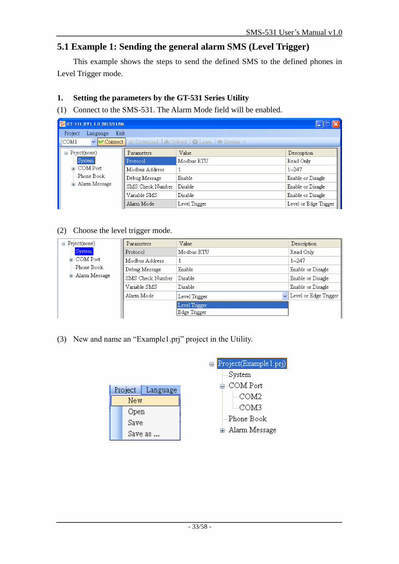
5.1 Example 1: Sending the general alarm SMS (Level Trigger)
This example shows the steps to send the defined SMS to the defined phones in
Level Trigger mode.
1. Setting the parameters by the GT-531 Series Utility
(1) Connect to the SMS-531. The Alarm Mode field will be enabled.
(2) Choose the level trigger mode.
(3) New and name an “Example1.prj” project in the Utility.
SMS-531 User’s Manual v1.0
- 34/58 -
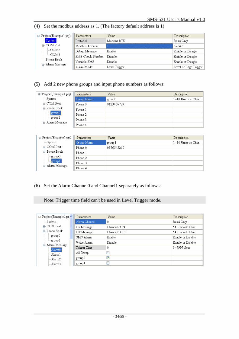
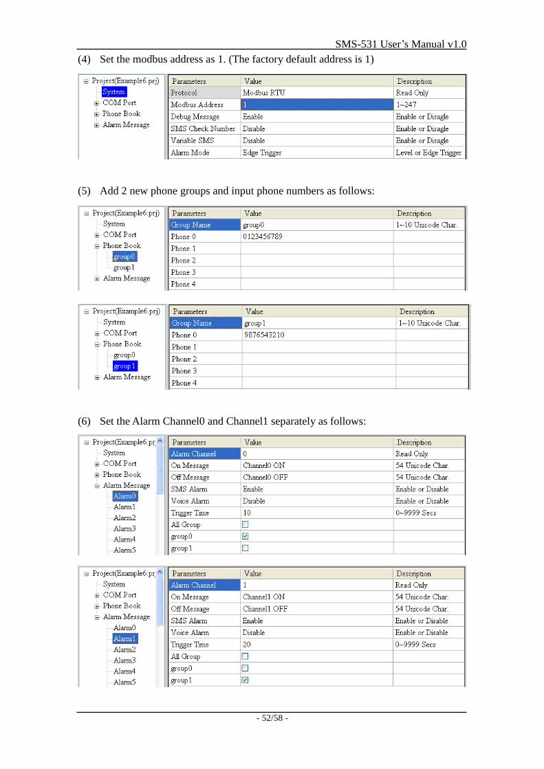
(4) Set the modbus address as 1. (The factory default address is 1)
(5) Add 2 new phone groups and input phone numbers as follows:
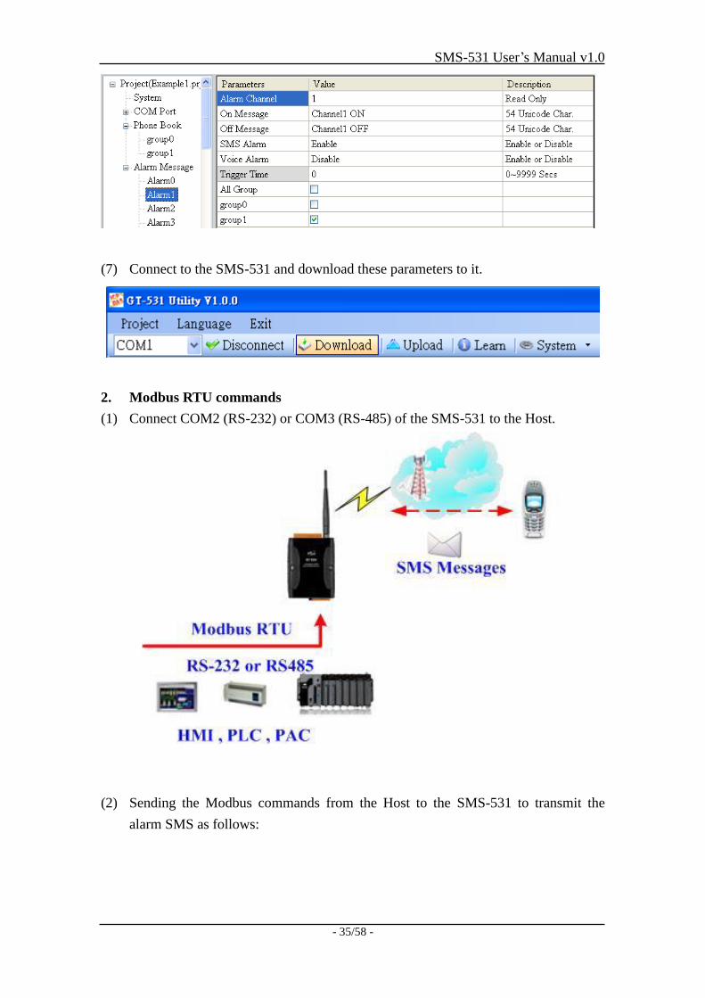
(6) Set the Alarm Channel0 and Channel1 separately as follows:
Note: Trigger time field can't be used in Level Trigger mode.
SMS-531 User’s Manual v1.0
- 35/58 -
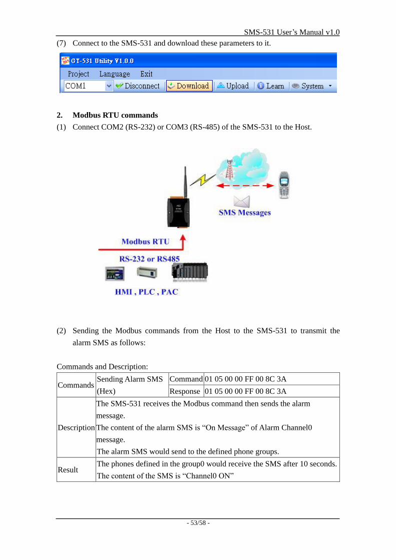
(7) Connect to the SMS-531 and download these parameters to it.
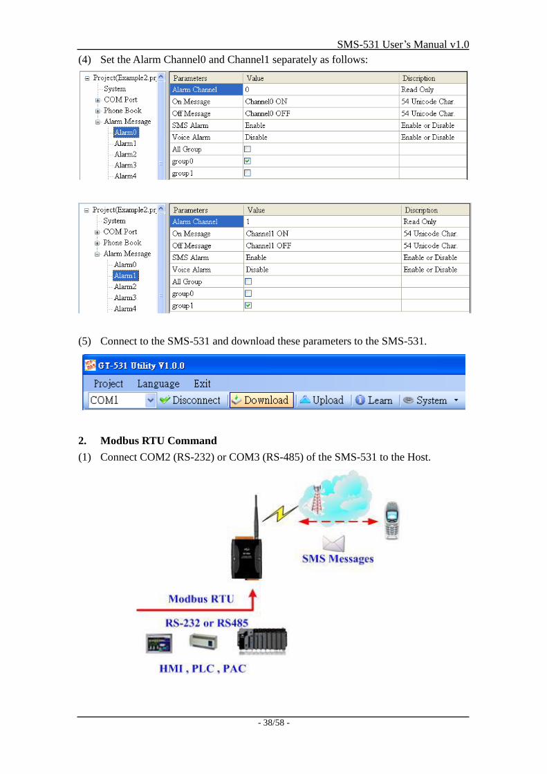
2. Modbus RTU commands
(1) Connect COM2 (RS-232) or COM3 (RS-485) of the SMS-531 to the Host.
(2) Sending the Modbus commands from the Host to the SMS-531 to transmit the
alarm SMS as follows:
SMS-531 User’s Manual v1.0
- 36/58 -
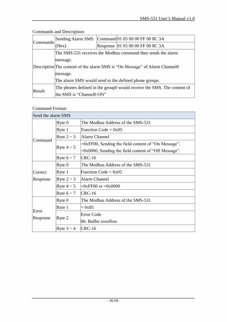
Commands and Description:
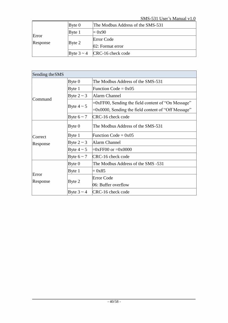
Commands Sending Alarm SMS
(Hex)
Command 01 05 00 00 FF 00 8C 3A
Response 01 05 00 00 FF 00 8C 3A
Description
The SMS-531 receives the Modbus command then sends the alarm
message.
The content of the alarm SMS is “On Message” of Alarm Channel0
message.
The alarm SMS would send to the defined phone groups.
Result The phones defined in the group0 would receive the SMS. The content of
the SMS is “Channel0 ON”
Command Format:
Send the alarm SMS
Command
Byte 0 The Modbus Address of the SMS-531
Byte 1 Function Code = 0x05
Byte 2 ~ 3 Alarm Channel
Byte 4 ~ 5 =0xFF00, Sending the field content of “On Message”.
=0x0000, Sending the field content of “Off Message”.
Byte 6 ~ 7 CRC-16
Correct
Response
Byte 0 The Modbus Address of the SMS-531
Byte 1 Function Code = 0x05
Byte 2 ~ 3 Alarm Channel
Byte 4 ~ 5 =0xFF00 or =0x0000
Byte 6 ~ 7 CRC-16
Error
Response
Byte 0 The Modbus Address of the SMS-531
Byte 1 = 0x85
Byte 2 Error Code
06: Buffer overflow
Byte 3 ~ 4 CRC-16
SMS-531 User’s Manual v1.0
- 37/58 -
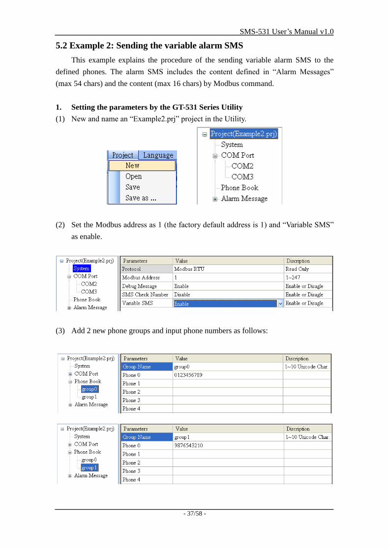
5.2 Example 2: Sending the variable alarm SMS
This example explains the procedure of the sending variable alarm SMS to the
defined phones. The alarm SMS includes the content defined in “Alarm Messages”
(max 54 chars) and the content (max 16 chars) by Modbus command.
1. Setting the parameters by the GT-531 Series Utility
(1) New and name an “Example2.prj” project in the Utility.
(2) Set the Modbus address as 1 (the factory default address is 1) and “Variable SMS”
as enable.
(3) Add 2 new phone groups and input phone numbers as follows:
SMS-531 User’s Manual v1.0
- 38/58 -
(4) Set the Alarm Channel0 and Channel1 separately as follows:
(5) Connect to the SMS-531 and download these parameters to the SMS-531.
2. Modbus RTU Command
(1) Connect COM2 (RS-232) or COM3 (RS-485) of the SMS-531 to the Host.
SMS-531 User’s Manual v1.0
- 39/58 -
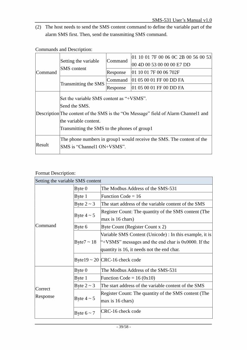
(2) The host needs to send the SMS content command to define the variable part of the
alarm SMS first. Then, send the transmitting SMS command.
Commands and Description:
Command
Setting the variable
SMS content
Command 01 10 01 7F 00 06 0C 2B 00 56 00 53
00 4D 00 53 00 00 00 E7 DD
Response 01 10 01 7F 00 06 702F
Transmitting the SMS Command 01 05 00 01 FF 00 DD FA
Response 01 05 00 01 FF 00 DD FA
Description
Set the variable SMS content as “+VSMS”.
Send the SMS.
The content of the SMS is the “On Message” field of Alarm Channel1 and
the variable content.
Transmitting the SMS to the phones of group1
Result The phone numbers in group1 would receive the SMS. The content of the
SMS is “Channel1 ON+VSMS”.
Format Description:
Setting the variable SMS content
Command
Byte 0 The Modbus Address of the SMS-531
Byte 1 Function Code = 16
Byte 2 ~ 3 The start address of the variable content of the SMS
Byte 4 ~ 5 Register Count: The quantity of the SMS content (The
max is 16 chars)
Byte 6 Byte Count (Register Count x 2)
Byte7 ~ 18
Variable SMS Content (Unicode) : In this example, it is
“+VSMS” messages and the end char is 0x0000. If the
quantity is 16, it needs not the end char.
Byte19 ~ 20 CRC-16 check code
Correct
Response
Byte 0 The Modbus Address of the SMS-531
Byte 1 Function Code = 16 (0x10)
Byte 2 ~ 3 The start address of the variable content of the SMS
Byte 4 ~ 5 Register Count: The quantity of the SMS content (The
max is 16 chars)
Byte 6 ~ 7 CRC-16 check code
SMS-531 User’s Manual v1.0
- 40/58 -
Error
Response
Byte 0 The Modbus Address of the SMS-531
Byte 1 = 0x90
Byte 2 Error Code
02: Format error
Byte 3 ~ 4 CRC-16 check code
Sending the SMS
Command
Byte 0 The Modbus Address of the SMS-531
Byte 1 Function Code = 0x05
Byte 2 ~ 3 Alarm Channel
Byte 4 ~ 5 =0xFF00, Sending the field content of “On Message”
=0x0000, Sending the field content of “Off Message”
Byte 6 ~ 7 CRC-16 check code
Correct
Response
Byte 0 The Modbus Address of the SMS-531
Byte 1 Function Code = 0x05
Byte 2 ~ 3 Alarm Channel
Byte 4 ~ 5 =0xFF00 or =0x0000
Byte 6 ~ 7 CRC-16 check code
Error
Response
Byte 0 The Modbus Address of the SMS -531
Byte 1 = 0x85
Byte 2 Error Code
06: Buffer overflow
Byte 3 ~ 4 CRC-16 check code
SMS-531 User’s Manual v1.0
- 41/58 -
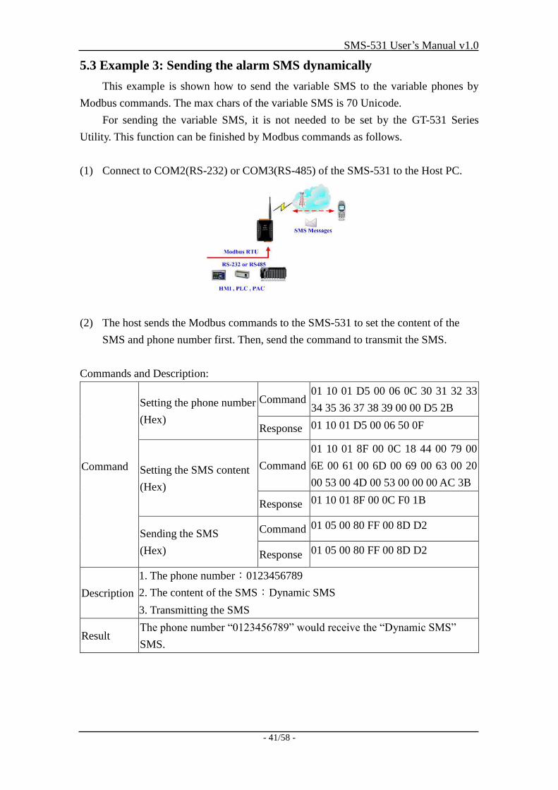
5.3 Example 3: Sending the alarm SMS dynamically
This example is shown how to send the variable SMS to the variable phones by
Modbus commands. The max chars of the variable SMS is 70 Unicode.
For sending the variable SMS, it is not needed to be set by the GT-531 Series
Utility. This function can be finished by Modbus commands as follows.
(1) Connect to COM2(RS-232) or COM3(RS-485) of the SMS-531 to the Host PC.
(2) The host sends the Modbus commands to the SMS-531 to set the content of the
SMS and phone number first. Then, send the command to transmit the SMS.
Commands and Description:
Command
Setting the phone number
(Hex)
Command 01 10 01 D5 00 06 0C 30 31 32 33
34 35 36 37 38 39 00 00 D5 2B
Response 01 10 01 D5 00 06 50 0F
Setting the SMS content
(Hex)
Command
01 10 01 8F 00 0C 18 44 00 79 00
6E 00 61 00 6D 00 69 00 63 00 20
00 53 00 4D 00 53 00 00 00 AC 3B
Response 01 10 01 8F 00 0C F0 1B
Sending the SMS
(Hex)
Command 01 05 00 80 FF 00 8D D2
Response 01 05 00 80 FF 00 8D D2
Description
1. The phone number:0123456789
2. The content of the SMS:Dynamic SMS
3. Transmitting the SMS
Result The phone number “0123456789” would receive the “Dynamic SMS”
SMS.
SMS-531 User’s Manual v1.0
- 42/58 -
Format Description:
Setting the variable phone number
Command
Byte 0 The Modbus Address of the SMS-531
Byte 1 Function Code = 16 (0x10)
Byte 2 ~ 3 The start address of the phone number
Byte 4 ~ 5 Register Count: The register size of the phone number
Byte 6 Byte Count(Register Counter x 2)
Byte7 ~ 18
The phone number (ASCII code). The end char is
0x00. If the number size is 20, it is needed not the end
char.
Byte 19 ~ 20 CRC-16 check code
Correct
response
Byte 0 The Modbus Address of the SMS-531
Byte 1 Function Code = 16 (0x10)
Byte 2 ~ 3 The start address of the phone number
Byte 4 ~ 5 Register Count: The register size of the phone number
Byte 6 ~ 7 CRC-16 check code
Error response
Byte 0 The Modbus Address of the SMS-531
Byte 1 = 0x90
Byte 2
Error Code
02: The SMS-531 is sending the SMS. The phone
number is unchangeable.
Byte 3 ~ 4 CRC-16 check code
Setting the content of the SMS
Command
Byte 0 The Modbus Address of the SMS-531
Byte 1 Function Code = 16 (0x10)
Byte 2 ~ 3 The start address of the sent SMS
Byte 4 ~ 5 Register Count: The size of the SMS. The max is 70
Unicode.
Byte 6 Byte Count(Register Counter x 2)
Byte7 ~ 30
The content of the SMS (Unicode code). The end char
is 0x0000. If the size of the SMS is 70, it is not needed
the end char.
Byte 31 ~ 32 CRC-16 check code
Correct
Response
Byte 0 The Modbus Address of the SMS-531
Byte 1 Function Code = 16 (0x10)
Byte 2 ~ 3 The start address of the sent SMS
Byte 4 ~ 5 Register Count: The size of the SMS. The max is 70
Unicode.
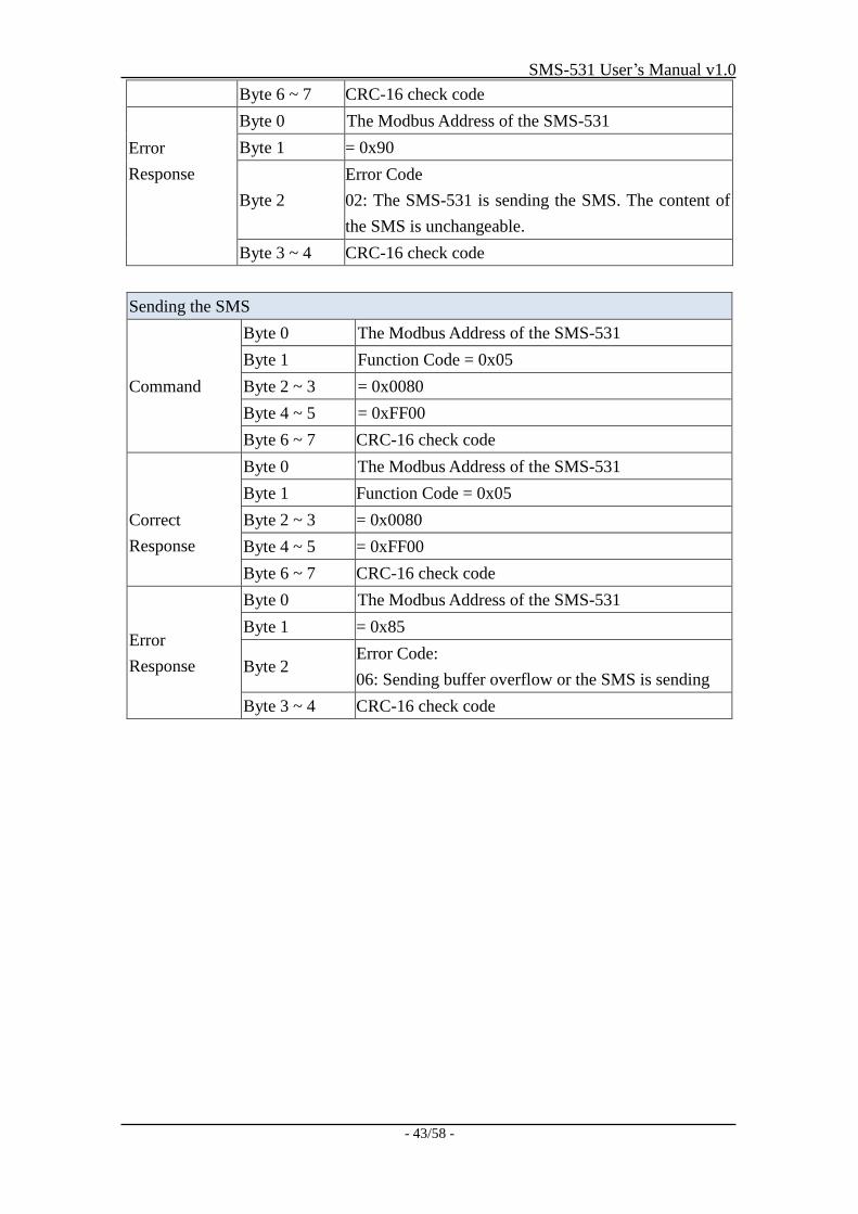
SMS-531 User’s Manual v1.0
- 43/58 -
Byte 6 ~ 7 CRC-16 check code
Error
Response
Byte 0 The Modbus Address of the SMS-531
Byte 1 = 0x90
Byte 2
Error Code
02: The SMS-531 is sending the SMS. The content of
the SMS is unchangeable.
Byte 3 ~ 4 CRC-16 check code
Sending the SMS
Command
Byte 0 The Modbus Address of the SMS-531
Byte 1 Function Code = 0x05
Byte 2 ~ 3 = 0x0080
Byte 4 ~ 5 = 0xFF00
Byte 6 ~ 7 CRC-16 check code
Correct
Response
Byte 0 The Modbus Address of the SMS-531
Byte 1 Function Code = 0x05
Byte 2 ~ 3 = 0x0080
Byte 4 ~ 5 = 0xFF00
Byte 6 ~ 7 CRC-16 check code
Error
Response
Byte 0 The Modbus Address of the SMS-531
Byte 1 = 0x85
Byte 2 Error Code:
06: Sending buffer overflow or the SMS is sending
Byte 3 ~ 4 CRC-16 check code
SMS-531 User’s Manual v1.0
- 44/58 -
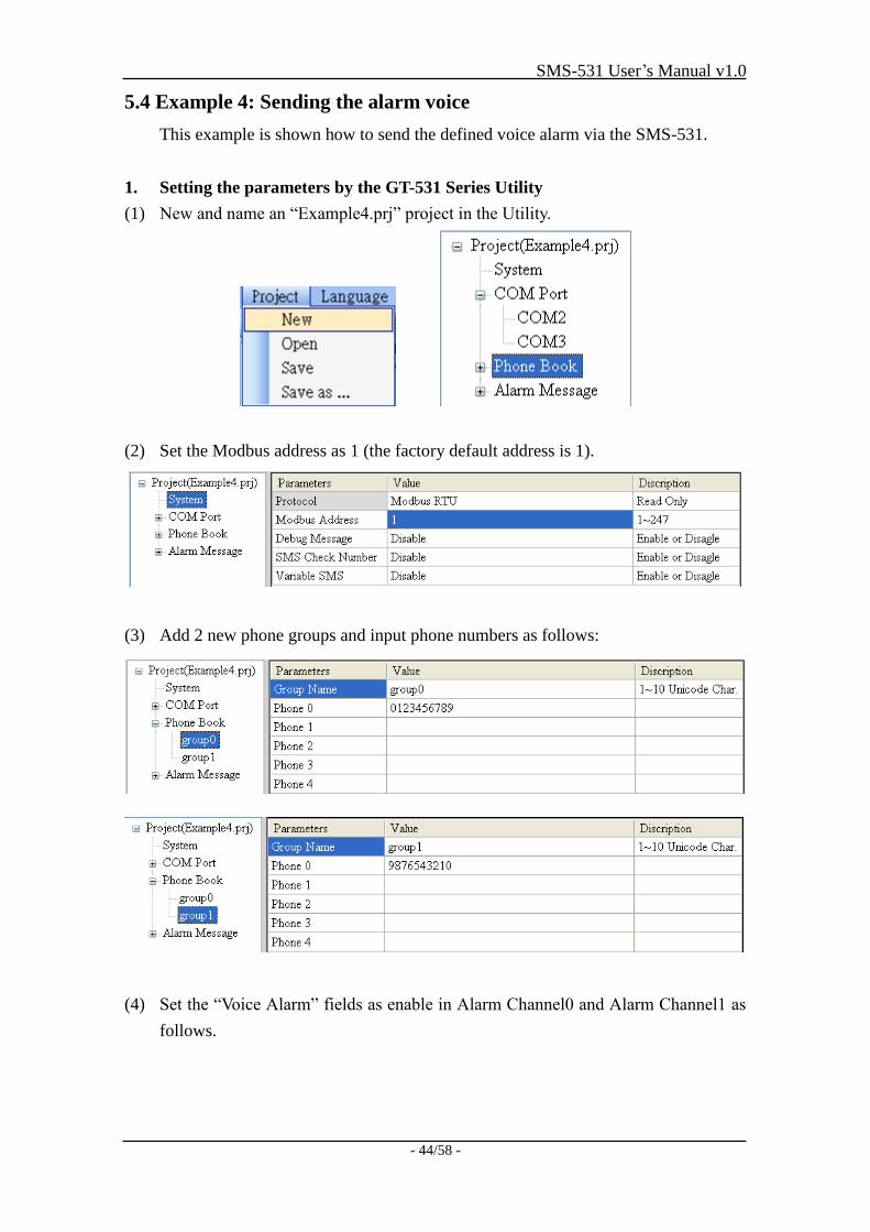
5.4 Example 4: Sending the alarm voice
This example is shown how to send the defined voice alarm via the SMS-531.
1. Setting the parameters by the GT-531 Series Utility
(1) New and name an “Example4.prj” project in the Utility.
(2) Set the Modbus address as 1 (the factory default address is 1).
(3) Add 2 new phone groups and input phone numbers as follows:
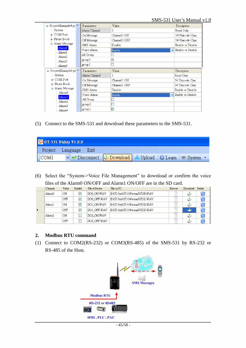
(4) Set the “Voice Alarm” fields as enable in Alarm Channel0 and Alarm Channel1 as
follows.
SMS-531 User’s Manual v1.0
- 45/58 -
(5) Connect to the SMS-531 and download these parameters to the SMS-531.
(6) Select the “System->Voice File Management” to download or confirm the voice
files of the Alarm0 ON/OFF and Alarm1 ON/OFF are in the SD card.
2. Modbus RTU command
(1) Connect to COM2(RS-232) or COM3(RS-485) of the SMS-531 by RS-232 or
RS-485 of the Host.
SMS-531 User’s Manual v1.0
- 46/58 -
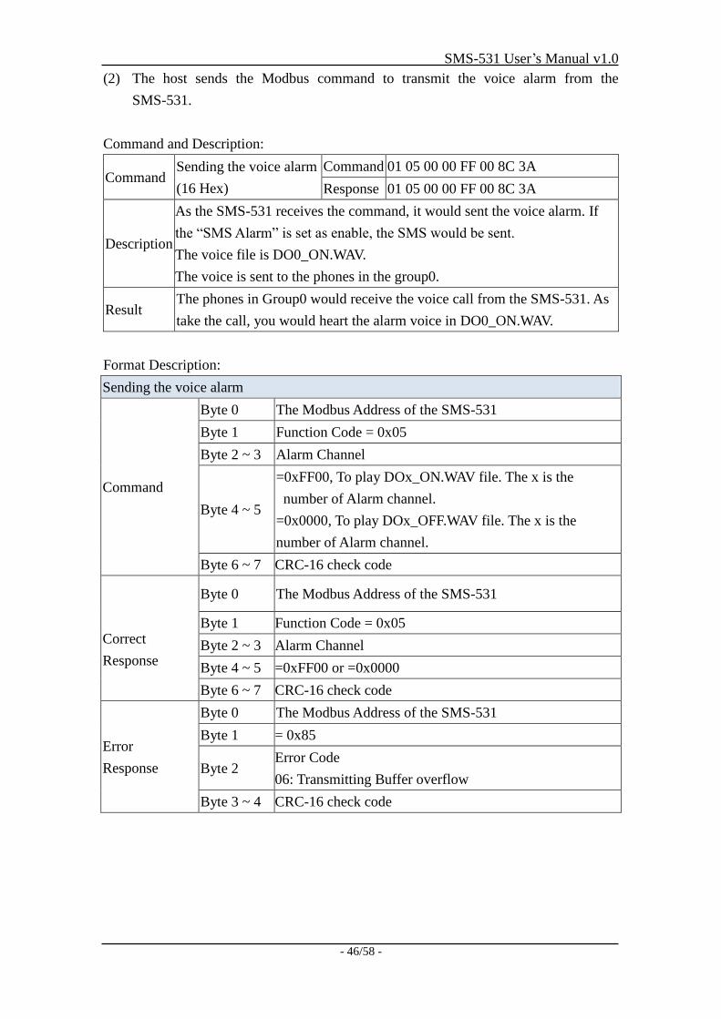
(2) The host sends the Modbus command to transmit the voice alarm from the
SMS-531.
Command and Description:
Command Sending the voice alarm
(16 Hex)
Command 01 05 00 00 FF 00 8C 3A
Response 01 05 00 00 FF 00 8C 3A
Description
As the SMS-531 receives the command, it would sent the voice alarm. If
the “SMS Alarm” is set as enable, the SMS would be sent.
The voice file is DO0_ON.WAV.
The voice is sent to the phones in the group0.
Result The phones in Group0 would receive the voice call from the SMS-531. As
take the call, you would heart the alarm voice in DO0_ON.WAV.
Format Description:
Sending the voice alarm
Command
Byte 0 The Modbus Address of the SMS-531
Byte 1 Function Code = 0x05
Byte 2 ~ 3 Alarm Channel
Byte 4 ~ 5
=0xFF00, To play DOx_ON.WAV file. The x is the
number of Alarm channel.
=0x0000, To play DOx_OFF.WAV file. The x is the
number of Alarm channel.
Byte 6 ~ 7 CRC-16 check code
Correct
Response
Byte 0 The Modbus Address of the SMS-531
Byte 1 Function Code = 0x05
Byte 2 ~ 3 Alarm Channel
Byte 4 ~ 5 =0xFF00 or =0x0000
Byte 6 ~ 7 CRC-16 check code
Error
Response
Byte 0 The Modbus Address of the SMS-531
Byte 1 = 0x85
Byte 2 Error Code
06: Transmitting Buffer overflow
Byte 3 ~ 4 CRC-16 check code
SMS-531 User’s Manual v1.0
- 47/58 -
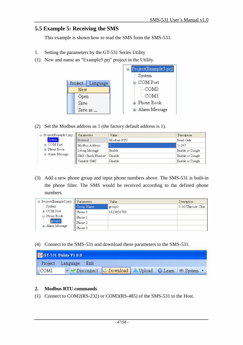
5.5 Example 5: Receiving the SMS
This example is shown how to read the SMS form the SMS-531.
1. Setting the parameters by the GT-531 Series Utility
(1) New and name an “Example5.prj” project in the Utility.
(2) Set the Modbus address as 1 (the factory default address is 1).
(3) Add a new phone group and input phone numbers above. The SMS-531 is built-in
the phone filter. The SMS would be received according to the defined phone
numbers.
(4) Connect to the SMS-531 and download these parameters to the SMS-531.
2. Modbus RTU commands
(1) Connect to COM2(RS-232) or COM3(RS-485) of the SMS-531 to the Host.
SMS-531 User’s Manual v1.0
- 48/58 -
(2) The host can send the Modbus command periodically to inquire the SMS-531
whether has received the SMS. If the SMS-531 has received the SMS, you can
send the command to read it.
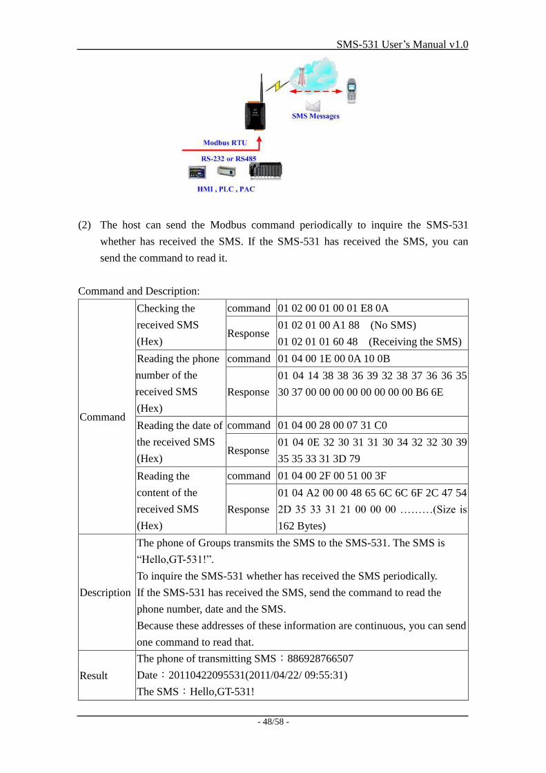
Command and Description:
Command
Checking the
received SMS
(Hex)
command 01 02 00 01 00 01 E8 0A
Response 01 02 01 00 A1 88 (No SMS)
01 02 01 01 60 48 (Receiving the SMS)
Reading the phone
number of the
received SMS
(Hex)
command 01 04 00 1E 00 0A 10 0B
Response
01 04 14 38 38 36 39 32 38 37 36 36 35
30 37 00 00 00 00 00 00 00 00 B6 6E
Reading the date of
the received SMS
(Hex)
command 01 04 00 28 00 07 31 C0
Response 01 04 0E 32 30 31 31 30 34 32 32 30 39
35 35 33 31 3D 79
Reading the
content of the
received SMS
(Hex)
command 01 04 00 2F 00 51 00 3F
Response
01 04 A2 00 00 48 65 6C 6C 6F 2C 47 54
2D 35 33 31 21 00 00 00 ………(Size is
162 Bytes)
Description
The phone of Groups transmits the SMS to the SMS-531. The SMS is
“Hello,GT-531!”.
To inquire the SMS-531 whether has received the SMS periodically.
If the SMS-531 has received the SMS, send the command to read the
phone number, date and the SMS.
Because these addresses of these information are continuous, you can send
one command to read that.
Result
The phone of transmitting SMS:886928766507
Date:20110422095531(2011/04/22/ 09:55:31)
The SMS:Hello,GT-531!
SMS-531 User’s Manual v1.0
- 49/58 -
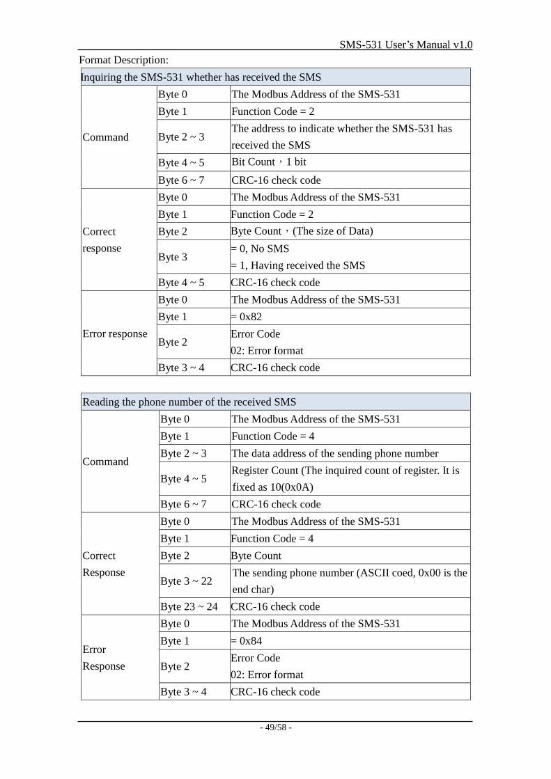
Format Description:
Inquiring the SMS-531 whether has received the SMS
Command
Byte 0 The Modbus Address of the SMS-531
Byte 1 Function Code = 2
Byte 2 ~ 3 The address to indicate whether the SMS-531 has
received the SMS
Byte 4 ~ 5 Bit Count,1 bit
Byte 6 ~ 7 CRC-16 check code
Correct
response
Byte 0 The Modbus Address of the SMS-531
Byte 1 Function Code = 2
Byte 2 Byte Count,(The size of Data)
Byte 3 = 0, No SMS
= 1, Having received the SMS
Byte 4 ~ 5 CRC-16 check code
Error response
Byte 0 The Modbus Address of the SMS-531
Byte 1 = 0x82
Byte 2 Error Code
02: Error format
Byte 3 ~ 4 CRC-16 check code
Reading the phone number of the received SMS
Command
Byte 0 The Modbus Address of the SMS-531
Byte 1 Function Code = 4
Byte 2 ~ 3 The data address of the sending phone number
Byte 4 ~ 5 Register Count (The inquired count of register. It is
fixed as 10(0x0A)
Byte 6 ~ 7 CRC-16 check code
Correct
Response
Byte 0 The Modbus Address of the SMS-531
Byte 1 Function Code = 4
Byte 2 Byte Count
Byte 3 ~ 22 The sending phone number (ASCII coed, 0x00 is the
end char)
Byte 23 ~ 24 CRC-16 check code
Error
Response
Byte 0 The Modbus Address of the SMS-531
Byte 1 = 0x84
Byte 2 Error Code
02: Error format
Byte 3 ~ 4 CRC-16 check code
SMS-531 User’s Manual v1.0
- 50/58 -
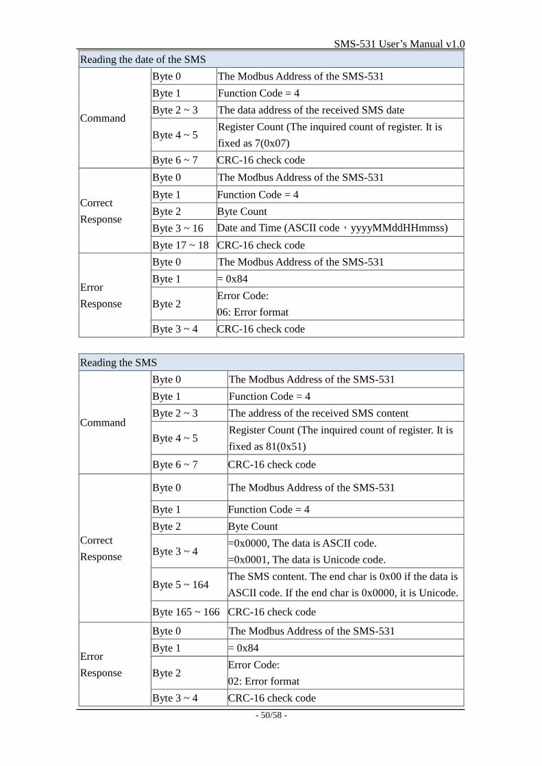
Reading the date of the SMS
Command
Byte 0 The Modbus Address of the SMS-531
Byte 1 Function Code = 4
Byte 2 ~ 3 The data address of the received SMS date
Byte 4 ~ 5 Register Count (The inquired count of register. It is
fixed as 7(0x07)
Byte 6 ~ 7 CRC-16 check code
Correct
Response
Byte 0 The Modbus Address of the SMS-531
Byte 1 Function Code = 4
Byte 2 Byte Count
Byte 3 ~ 16 Date and Time (ASCII code,yyyyMMddHHmmss)
Byte 17 ~ 18 CRC-16 check code
Error
Response
Byte 0 The Modbus Address of the SMS-531
Byte 1 = 0x84
Byte 2 Error Code:
06: Error format
Byte 3 ~ 4 CRC-16 check code
Reading the SMS
Command
Byte 0 The Modbus Address of the SMS-531
Byte 1 Function Code = 4
Byte 2 ~ 3 The address of the received SMS content
Byte 4 ~ 5 Register Count (The inquired count of register. It is
fixed as 81(0x51)
Byte 6 ~ 7 CRC-16 check code
Correct
Response
Byte 0 The Modbus Address of the SMS-531
Byte 1 Function Code = 4
Byte 2 Byte Count
Byte 3 ~ 4 =0x0000, The data is ASCII code.
=0x0001, The data is Unicode code.
Byte 5 ~ 164 The SMS content. The end char is 0x00 if the data is
ASCII code. If the end char is 0x0000, it is Unicode.
Byte 165 ~ 166 CRC-16 check code
Error
Response
Byte 0 The Modbus Address of the SMS-531
Byte 1 = 0x84
Byte 2 Error Code:
02: Error format
Byte 3 ~ 4 CRC-16 check code
SMS-531 User’s Manual v1.0
- 51/58 -
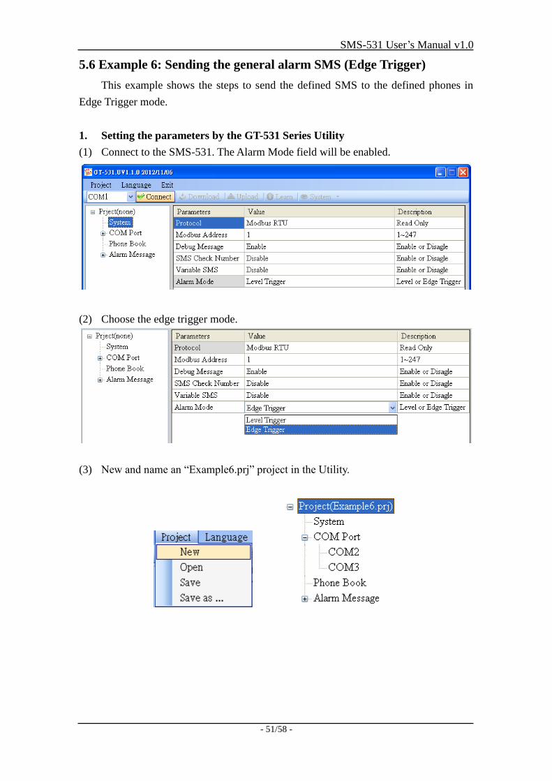
5.6 Example 6: Sending the general alarm SMS (Edge Trigger)
This example shows the steps to send the defined SMS to the defined phones in
Edge Trigger mode.
1. Setting the parameters by the GT-531 Series Utility
(1) Connect to the SMS-531. The Alarm Mode field will be enabled.
(2) Choose the edge trigger mode.
(3) New and name an “Example6.prj” project in the Utility.
SMS-531 User’s Manual v1.0
- 52/58 -
(4) Set the modbus address as 1. (The factory default address is 1)
(5) Add 2 new phone groups and input phone numbers as follows:
(6) Set the Alarm Channel0 and Channel1 separately as follows:
SMS-531 User’s Manual v1.0
- 53/58 -
(7) Connect to the SMS-531 and download these parameters to it.
2. Modbus RTU commands
(1) Connect COM2 (RS-232) or COM3 (RS-485) of the SMS-531 to the Host.
(2) Sending the Modbus commands from the Host to the SMS-531 to transmit the
alarm SMS as follows:
Commands and Description:
Commands Sending Alarm SMS
(Hex)
Command 01 05 00 00 FF 00 8C 3A
Response 01 05 00 00 FF 00 8C 3A
Description
The SMS-531 receives the Modbus command then sends the alarm
message.
The content of the alarm SMS is “On Message” of Alarm Channel0
message.
The alarm SMS would send to the defined phone groups.
Result The phones defined in the group0 would receive the SMS after 10 seconds.
The content of the SMS is “Channel0 ON”
SMS-531 User’s Manual v1.0
- 54/58 -
Command Format:
Send the alarm SMS
Command
Byte 0 The Modbus Address of the SMS-531
Byte 1 Function Code = 0x05
Byte 2 ~ 3 Alarm Channel
Byte 4 ~ 5 =0xFF00, Sending the field content of “On Message”.
=0x0000, Sending the field content of “Off Message”.
Byte 6 ~ 7 CRC-16
Correct
Response
Byte 0 The Modbus Address of the SMS-531
Byte 1 Function Code = 0x05
Byte 2 ~ 3 Alarm Channel
Byte 4 ~ 5 =0xFF00 or =0x0000
Byte 6 ~ 7 CRC-16
Error
Response
Byte 0 The Modbus Address of the SMS-531
Byte 1 = 0x85
Byte 2
Error Code
06: Buffer overflow
13: Alarm status are the same (EX: Original status is ON,
want to change the status to ON)
Byte 3 ~ 4 CRC-16
SMS-531 User’s Manual v1.0
- 55/58 -
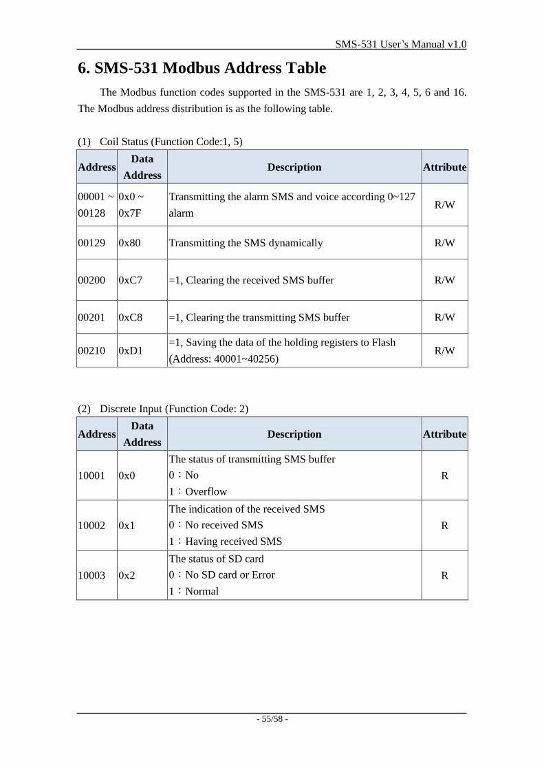
6. SMS-531 Modbus Address Table
The Modbus function codes supported in the SMS-531 are 1, 2, 3, 4, 5, 6 and 16.
The Modbus address distribution is as the following table.
(1) Coil Status (Function Code:1, 5)
Address Data
Address Description Attribute
00001 ~
00128
0x0 ~
0x7F
Transmitting the alarm SMS and voice according 0~127
alarm R/W
00129 0x80 Transmitting the SMS dynamically R/W
00200 0xC7 =1, Clearing the received SMS buffer R/W
00201 0xC8 =1, Clearing the transmitting SMS buffer R/W
00210 0xD1 =1, Saving the data of the holding registers to Flash
(Address: 40001~40256) R/W
(2) Discrete Input (Function Code: 2)
Address Data
Address Description Attribute
10001 0x0
The status of transmitting SMS buffer
0:No
1:Overflow
R
10002 0x1
The indication of the received SMS
0:No received SMS
1:Having received SMS
R
10003 0x2
The status of SD card
0:No SD card or Error
1:Normal
R
SMS-531 User’s Manual v1.0
- 56/58 -
(3) Input Register (Function Code: 4)
Address Data
Address Description Attribute
30001 ~
30016
0x0 ~
0xF
The status of transmitting SMS buffer 0~15
(1) High Byte:Buffer status
0-> Idle
1-> Waiting for transmitting
2-> Transmitting
3-> Transmitting OK
4-> Transmitting fault
(2) Low Byte :Error code
R
30017 0x10 The last transmitting SMS buffer number R
30018 0x11
The status of transmitting dynamic SMS
(1) High Byte:Status
0-> Idle
1-> System busy or waiting for transmitting
2-> Transmitting
3-> Transmitting OK
4-> Transmitting fault
(2) Low Byte:Error code
R
30019 0x12 The 3G signal strength
0~31s or 99(Error) R
30031 ~
30040
0x1E ~
0x27
The SMS transmitter’s phone number. ASCII code by
end char 0x00. R
30041 ~
30047
0x28 ~
0x2E The date and time of receiving SMS R
30048 0x2F
The format of the received SMS
0x0000=ASCII
0x0001=Unicode
R
30049 ~
30128
0x30 ~
0x7F
The content of the received SMS
ASCII: By end char 0x00
Unicode:By end char 0x0000
R
Note: Query the status of transmitting SMS can't be used in Edge Trigger mode.
SMS-531 User’s Manual v1.0
- 57/58 -
(4) Holding Register(Output Register) (Function Code: 3, 6, 16)
Address Data
Address Description Attribute
40200 0xC7 Module Address(Modbus Net ID),1~247 R/W
40201 0xC8
COM2
(1) High Byte
Code 0x04 0x05 0x06 0x07
Baud 2400 4800 9600 19200
Code 0x08 0x09 0x0A
Baud 38400 57600 115200
(2) Low Byte
Bit 2:0 (Data Bit)
011:8 Data Bits
Bite 4:3(stop bit)
00:1 stop bit
01:2 stop bit
Bite 6:5(parity)
00:no parity
01:odd parity
10:even parity
R/W
40202 0xC9 COM3 setting. The data format is as COM2 R/W
40207 0xCE
Enabling or Disabling the debug message
0x0000=Disable
0x0001=Enable
R/W
40208 0xCF
Enabling or Disabling the SMS with the check code
0x0000=Disable
0x0001=Enable
R/W
40384 ~
40399
0x17F ~
0x18E
The variable content of the SMS (Unicode by the end
char 0x0000) R/W
40400 ~
40469
0x18F ~
0x1D4
The dynamic transmitting SMS content (Unicode by the
end char 0x0000) R/W
40470 ~
40479
0x1D5 ~
0x1DE
The phone number for the dynamic transmitting SMS
(ASCII by the end char 0x00) R/W
SMS-531 User’s Manual v1.0
- 58/58 -
7. Troubleshooting
Item Trouble state Solution
1 STA is always on
1. Check SIM card.
2. Check Antenna.
3. Check the 3G signal strength.
2 STA led is blanking per 50 ms.
It shows the SIM card needs to input PIN or
PUK code. The SMS-531 is not set these code
or the wrong codes. You can set these code
in ”System->Input PIN/PUK”.
3 The GT-531 Series Utility can
not connect to the SMS-531
1. Check STA LED blinking every 1 sec.
2. Check the COM port wire connection.
4 Can not receive the SMS Please confirm the transmitter’s phone number
is in the groups.
5 The defined phone received an
abnormal SMS
The SMS-531 support only Unicode SMS.
Confirm the defined SMS content is Unicode.
6 The SMS-531 is not replied by
Modbus command
1. Confirm the wire connection.
2. Confirm the Modbus ID of the SMS-531.
3. Confirm the COM port configuration.
7 Can not hear the voice alarm
from the SMS-531
Confirm the SD card is normal and the voice file
is in it.
8 SMS DBS could not received the
SMS from SMS-531
User must add “ALARM;” to the start of the
short message.