Embed Size (px)
Citation preview
LUMINESCENCE TECHNIQUES: INSTRUMENTATION
AND METHODS
LARS BéTTER-JENSEN*
Risù National Laboratory, DK 4000 Roskilde, Denmark
AbstractÐThis paper describes techniques, instruments and methods used in luminescence dating andenvironmental dosimetry in many laboratories around the world. These techniques are based on twophenomena ± thermally stimulated luminescence and optically stimulated luminescence. The most com-monly used luminescence stimulation and detection techniques are reviewed and information is givenon recent developments in instrument design and on the state of the art in luminescence measurementsand analysis. # 1998 Elsevier Science Ltd. All rights reserved
1. INTRODUCTION
Luminescence arises from stimulation, either ther-
mal or optical, of minerals that have been pre-
viously exposed to ionising radiation. During
exposure, radiation energy is accumulated and
stored in the crystal lattice; this energy is stored in
the form of electrons that have been trapped at
defects in the lattice. During stimulation, the
trapped charge is released and as a result the lumi-
nescence signal becomes zero. Radiation-induced
luminescence should be distinguished from other
luminescence phenomena, e.g. photoluminescence,
phosphorescence, etc. which are not dose dependent
and thus not relevant to dating or dosimetry.
Thermally stimulated luminesence, usually called
thermoluminescence (TL), has been used extensively
since the early 1950s to measure nuclear radiation
doses (Daniels et al., 1953), following the commer-
cial availability of su�ciently sensitive and reliable
photomultiplier (PM) tubes. TL was subsequently
applied to archaeological dating in the early 1960s
(e.g. Aitken et al., 1964, 1968a; Mejdahl, 1969) and
to geological dating in the early 1980s (e.g. Wintle
and Huntley, 1980).
Optically stimulated luminescence (OSL) was
introduced for dating by Huntley et al. (1985), who
selected the 514 nm line from an argon laser to
stimulate luminescence from quartz. This technique
was subsequently taken up by other laboratories
using both quartz and feldspar, and a variety of
stimulation light sources (HuÈ tt et al., 1988; Aitken
and Smith, 1988; Spooner and Questiaux, 1990;
Poolton and Baili�, 1989; Bùtter-Jensen et al., 1991;
Bùtter-Jensen and Duller, 1992). An immediate ad-
vantage of OSL over TL is that it is normally
measured at or close to room temperature and is
thus a less destructive method. OSL also measures
only the component of the trapped electron popu-lation that is most sensitive to light. In geologicaldating, this is important because this component is
most likely to be emptied (or ``reset'') during trans-port prior to deposition and burial.More recently, luminescence techniques similar to
those used in dating have been adopted for retro-spective dose assessment, i.e. reconstruction of radi-ation doses received by the general population after
nuclear accidents. Typically, radiation doses aredetermined from TL or OSL measurements carriedout on quartz and feldspar samples extracted frombricks, tiles, pottery or porcelain items collected in
nuclear accident areas such as Chernobyl (e.g.Godfrey-Smith and Haskell, 1993; Baili�, 1995;Bùtter-Jensen et al., 1996).
In the following sections these di�erent lumines-cence dating and dosimetry techniques and methodsare described and information is provided on recent
achievements in instrument development and inluminescence detection and analysis.
2. THE PM TUBE, ELECTRONICS ANDSAMPLES
Both TL and OSL are normally detected using aphotomultiplier tube which, after 40 years, still con-stitutes the vital component in a luminescence
measurement system. The photomultiplier is a vac-uum tube that includes a photosensitive cathode, anumber of electron multiplying dynodes and ananode normally held at about 1000 V. Light pho-
tons interact with the photoelectric cathode material(e.g. potassium±caesium), causing the emission ofelectrons which are then attracted to the positive
voltage of the ®rst dynode. Depending on thedynode material (e.g. antimony±caesium), two or
Radiation Measurements Vol. 27, No. 5/6, pp. 749±768, 1997# 1998 Elsevier Science Ltd. All rights reserved
Printed in Great Britain1350-4487/98 $19.00+0.00PII: S1350-4487(97)00206-0
*To whom all correspondence should be addressed.
749
three electrons are then emitted for each electron
striking it. These electrons are again attracted by
the next dynode, and so on, resulting in several
million electrons reaching the anode for each elec-
tron emitted from the cathode. Thus a light photon
reaching the photocathode is converted to an elec-
trical pulse at the anode. However, not all photons
are converted to pulses and, additionally, the
photomultiplier is not equally sensitive to photons
emitted at di�erent wavelengths. This results in a
quantum e�ciency of up to 25%, depending on the
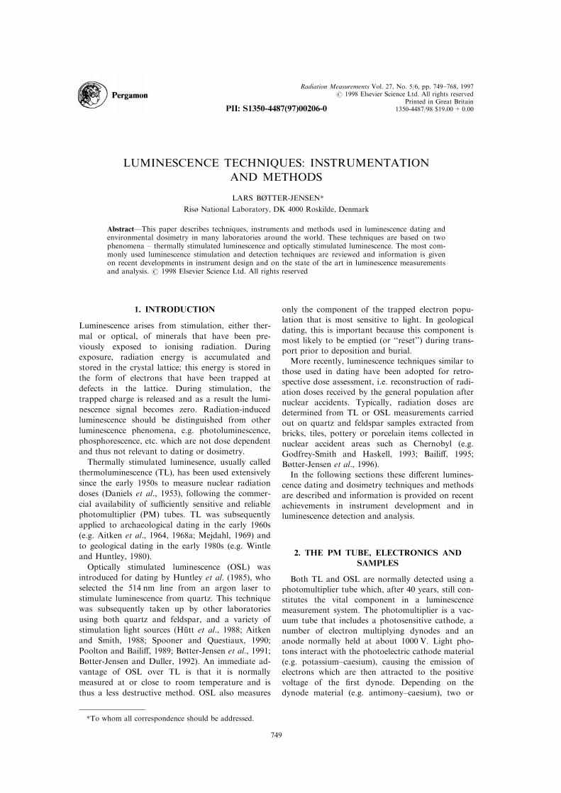
wavelength. Typically, a bialkali PM tube, such as
EMI 9235, has a selective response curve with a
maximum detection e�ciency peaking around
400 nm, which is suitable for the luminescence emis-
sion spectra from both quartz and feldspars. Other
types of PM tubes, such as EMI 9658 and RCA
31034, are available with an extended sensitivity in
the red region (S-20 cathode) which is particularly
suitable for the investigation of the red-emission
from some feldspar types (e.g. Visocekas, 1993). S-
20 cathode PM tubes normally need cooling to
reduce the dark noise, using commercially available
Peltier-element coolers. The quantum e�ciency ver-
sus photon energy or wavelength is shown for
bialkali and S-20 PM tubes in Fig. 1.
In principle, the PM tube can be operated in two
modes. One method is based on smoothing the
pulses arriving at the PM anode and thereby gener-
ating a DC current signal that, if ampli®ed and fed
to a recorder, is able to directly produce a TL glow
curve (see Section 3.1). Digitising the DC signal
may be performed using a current-to-pulse rate con-
verter system which allows a wide response range of
the order of 7 decades, and the possibility of o�set-
ting the dark current to zero (Shapiro, 1970).
However, a more sensitive mode is to directly count
the single pulses generated from light photons inter-
acting with the photocathode, and using a fast
pulse ampli®er and a pulse height discriminator tofeed a ratemeter or scaler (e.g. Aitken et al., 1968b;
Aitken, 1985). Modern bialkali PM tubes, such asEMI 9235QA, are now available with a dark countrate of less than 20 cps at room temperature. A
further advantage of the single photon countingtechnique is that the counts accumulated during ameasurement can be directly converted into absol-
ute light intensity without knowledge of the PMampli®cation factor; this facilitates comparisonbetween di�erent systems.
Samples for luminescence measurements are typi-cally prepared either as multiple mineral ®ne grains(<10 microns) or pure mineral coarse grains(>100 microns) on standardised 0.5-mm thick steel
or aluminium discs of diameter 10 mm.Alternatively, samples can be prepared in 10-mmdepressed cups made of 0.1-mm thick nickel or
platinum foils. During TL and OSL measurementsthe discs or cups are placed on a heater elementplate or lifted into a focused stimulation light
beam, respectively.
3. THERMALLY STIMULATEDLUMINESCENCE
3.1. Glow curves
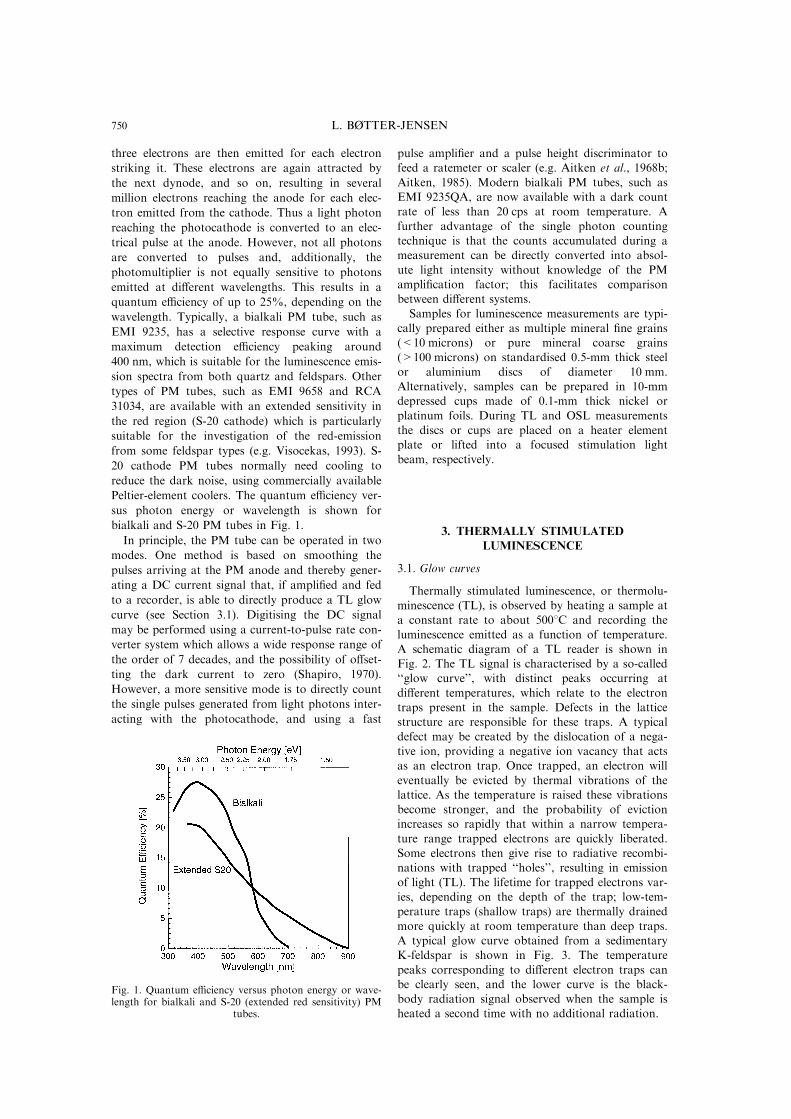
Thermally stimulated luminescence, or thermolu-minescence (TL), is observed by heating a sample ata constant rate to about 5008C and recording the
luminescence emitted as a function of temperature.A schematic diagram of a TL reader is shown inFig. 2. The TL signal is characterised by a so-called``glow curve'', with distinct peaks occurring at
di�erent temperatures, which relate to the electrontraps present in the sample. Defects in the latticestructure are responsible for these traps. A typical
defect may be created by the dislocation of a nega-tive ion, providing a negative ion vacancy that actsas an electron trap. Once trapped, an electron will
eventually be evicted by thermal vibrations of thelattice. As the temperature is raised these vibrationsbecome stronger, and the probability of evictionincreases so rapidly that within a narrow tempera-
ture range trapped electrons are quickly liberated.Some electrons then give rise to radiative recombi-nations with trapped ``holes'', resulting in emission
of light (TL). The lifetime for trapped electrons var-ies, depending on the depth of the trap; low-tem-perature traps (shallow traps) are thermally drained
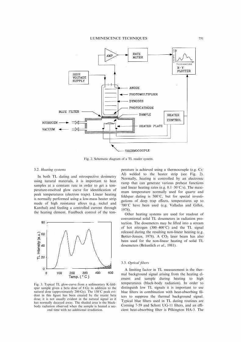
more quickly at room temperature than deep traps.A typical glow curve obtained from a sedimentaryK-feldspar is shown in Fig. 3. The temperature
peaks corresponding to di�erent electron traps canbe clearly seen, and the lower curve is the black-body radiation signal observed when the sample isheated a second time with no additional radiation.
Fig. 1. Quantum e�ciency versus photon energy or wave-length for bialkali and S-20 (extended red sensitivity) PM
tubes.
L. BéTTER-JENSEN750
3.2. Heating systems
In both TL dating and retrospective dosimetry
using natural materials, it is important to heat
samples at a constant rate in order to get a tem-perature-resolved glow curve for identi®cation of
peak temperatures (electron traps). Linear heating
is normally performed using a low-mass heater strip
made of high resistance alloys (e.g. nickel andKanthal) and feeding a controlled current through
the heating element. Feedback control of the tem-
perature is achieved using a thermocouple (e.g. Cr/Al) welded to the heater strip (see Fig. 2).Normally, heating is controlled by an electronic
ramp that can generate various preheat functionsand linear heating rates (e.g. 0.1±308C/s). The maxi-mum temperature normally used for quartz and
feldspar dating is 5008C, but for special investi-gations of deep trap e�ects, temperatures up to7008C have been used (e.g. Valladas and Gillot,
1978).Other heating systems are used for readout of
conventional solid TL dosemeters in radiation pro-
tection. The dosemeters may be lifted into a streamof hot nitrogen (300±4008C) and the TL signalreleased during the resulting non-linear heating (e.g.Bùtter-Jensen, 1978). A CO2 laser beam has also
been used for the non-linear heating of solid TLdosemeters (BraÈ unlich et al., 1981).
3.3. Optical ®lters
A limiting factor in TL measurement is the ther-mal background signal arising from the heating el-ement and sample during heating to high
temperatures (black-body radiation). In order todistinguish low TL signals it is important to useblue ®lters in combination with heat-absorbing ®l-
ters to suppress the thermal background signal.Typical blue ®lters used in TL dating routines areCorning 7-59 and Schott UG-11 ®lters, and an e�-cient heat-absorbing ®lter is Pilkington HA-3. The
Fig. 2. Schematic diagram of a TL reader system.
Fig. 3. Typical TL glow-curve from a sedimentary K-feld-spar sample given a beta dose of 8 Gy in addition to thenatural dose (approximately 200 Gy). The 1508C peak evi-dent in this ®gure has been created by the recent betadose; it is not usually evident in the natural signal as ithas normally decayed away. The shaded area is the black-body radiation observed when the sample is heated a sec-
ond time with no additional irradiation.
LUMINESCENCE TECHNIQUES 751
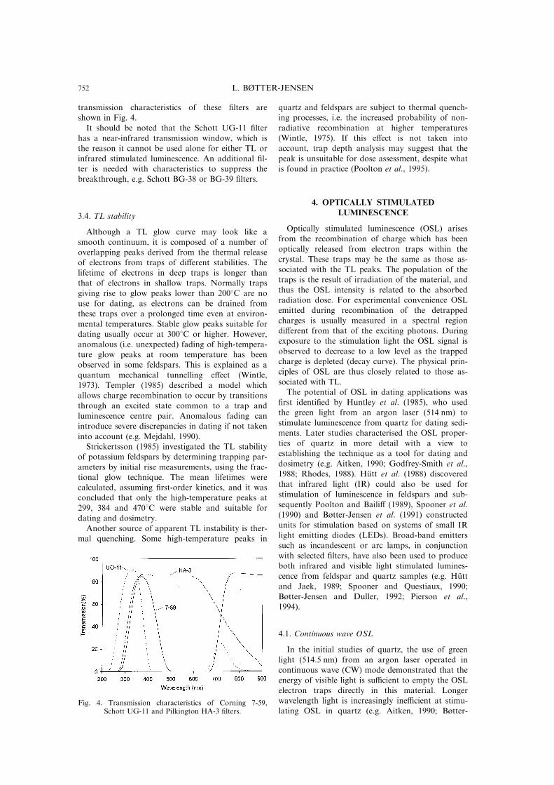
transmission characteristics of these ®lters areshown in Fig. 4.
It should be noted that the Schott UG-11 ®lterhas a near-infrared transmission window, which isthe reason it cannot be used alone for either TL or
infrared stimulated luminescence. An additional ®l-ter is needed with characteristics to suppress thebreakthrough, e.g. Schott BG-38 or BG-39 ®lters.
3.4. TL stability
Although a TL glow curve may look like a
smooth continuum, it is composed of a number ofoverlapping peaks derived from the thermal releaseof electrons from traps of di�erent stabilities. The
lifetime of electrons in deep traps is longer thanthat of electrons in shallow traps. Normally trapsgiving rise to glow peaks lower than 2008C are no
use for dating, as electrons can be drained fromthese traps over a prolonged time even at environ-mental temperatures. Stable glow peaks suitable for
dating usually occur at 3008C or higher. However,anomalous (i.e. unexpected) fading of high-tempera-ture glow peaks at room temperature has beenobserved in some feldspars. This is explained as a
quantum mechanical tunnelling e�ect (Wintle,1973). Templer (1985) described a model whichallows charge recombination to occur by transitions
through an excited state common to a trap andluminescence centre pair. Anomalous fading canintroduce severe discrepancies in dating if not taken
into account (e.g. Mejdahl, 1990).Strickertsson (1985) investigated the TL stability
of potassium feldspars by determining trapping par-
ameters by initial rise measurements, using the frac-tional glow technique. The mean lifetimes werecalculated, assuming ®rst-order kinetics, and it wasconcluded that only the high-temperature peaks at
299, 384 and 4708C were stable and suitable fordating and dosimetry.Another source of apparent TL instability is ther-
mal quenching. Some high-temperature peaks in
quartz and feldspars are subject to thermal quench-ing processes, i.e. the increased probability of non-
radiative recombination at higher temperatures(Wintle, 1975). If this e�ect is not taken intoaccount, trap depth analysis may suggest that the
peak is unsuitable for dose assessment, despite whatis found in practice (Poolton et al., 1995).
4. OPTICALLY STIMULATEDLUMINESCENCE
Optically stimulated luminescence (OSL) arisesfrom the recombination of charge which has been
optically released from electron traps within thecrystal. These traps may be the same as those as-sociated with the TL peaks. The population of thetraps is the result of irradiation of the material, and
thus the OSL intensity is related to the absorbedradiation dose. For experimental convenience OSLemitted during recombination of the detrapped
charges is usually measured in a spectral regiondi�erent from that of the exciting photons. Duringexposure to the stimulation light the OSL signal is
observed to decrease to a low level as the trappedcharge is depleted (decay curve). The physical prin-ciples of OSL are thus closely related to those as-
sociated with TL.The potential of OSL in dating applications was
®rst identi®ed by Huntley et al. (1985), who usedthe green light from an argon laser (514 nm) to
stimulate luminescence from quartz for dating sedi-ments. Later studies characterised the OSL proper-ties of quartz in more detail with a view to
establishing the technique as a tool for dating anddosimetry (e.g. Aitken, 1990; Godfrey-Smith et al.,1988; Rhodes, 1988). HuÈ tt et al. (1988) discovered
that infrared light (IR) could also be used forstimulation of luminescence in feldspars and sub-sequently Poolton and Baili� (1989), Spooner et al.
(1990) and Bùtter-Jensen et al. (1991) constructedunits for stimulation based on systems of small IRlight emitting diodes (LEDs). Broad-band emitterssuch as incandescent or arc lamps, in conjunction
with selected ®lters, have also been used to produceboth infrared and visible light stimulated lumines-cence from feldspar and quartz samples (e.g. HuÈ tt
and Jaek, 1989; Spooner and Questiaux, 1990;Bùtter-Jensen and Duller, 1992; Pierson et al.,1994).
4.1. Continuous wave OSL
In the initial studies of quartz, the use of greenlight (514.5 nm) from an argon laser operated incontinuous wave (CW) mode demonstrated that the
energy of visible light is su�cient to empty the OSLelectron traps directly in this material. Longerwavelength light is increasingly ine�cient at stimu-lating OSL in quartz (e.g. Aitken, 1990; Bùtter-
Fig. 4. Transmission characteristics of Corning 7-59,Schott UG-11 and Pilkington HA-3 ®lters.
L. BéTTER-JENSEN752
Jensen et al., 1994a). In contrast, luminescence can
be excited in feldspars with wavelengths in the near
infrared, because of one or more excitation reson-
ances in this material. This has been explained in
terms of a two-step thermo-optical process (HuÈ tt et
al., 1988) where charge is promoted from the
ground state of the defect to a series of metastable
excited states. This di�erence in stimulation charac-
teristics can be made use of in various ways, e.g.
for testing the purity of quartz samples and for
measurements of mixed samples (e.g. Spooner and
Questiaux, 1990; Bùtter-Jensen and Duller, 1992).
Thus the two main stimulation methods currently
being used in routine OSL dating are: (i) infrared
stimulated luminescence (IRSL), which is useful
only with feldspars, and (ii) green light stimulated
luminescence (GLSL), which works with both feld-
spars and quartz. GLSL is also e�ective with cer-
amics (porcelain) and some synthetic materials such
as Al2O3:C (Bùtter-Jensen and McKeever, 1996;
Bùtter-Jensen et al., 1997a).
In both IRSL and GLSL it is vital to avoid the
excitation light source a�ecting the PM tube. This
is achieved by a combination of suitable optical
stimulation and detection ®lters.
4.1.1. Continuous wave (CW) IRSL. In CW
IRSL it is comparatively easy to separate the stimu-
lation wavelengths (typically centered around
850 nm) from the luminescence emission of feld-
spars (380±420 nm). As the IR light emitted from
an IR light emitting diode is a narrow band (e.g.
for TEMPT 484 LED: 880 R 80 nm) it is only a
matter of protecting the PM tube with a detection
®lter with high attenuation in the infrared range
and a high transmission in the visible range. A
widely used ®lter is a Schott BG-39 which is a blue-
green transmission ®lter with excellent character-
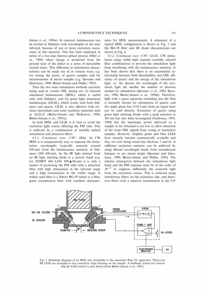
istics for IRSL measurements. A schematic of a
typical IRSL con®guration is shown in Fig. 5 and
the BG-39 ®lter and IR diode characteristics are
shown in Fig. 6.4.1.2. Continuous wave (CW) GLSL. CW stimu-
lation using visible light requires carefully selected
®lter combinations to prevent the stimulation light
from interfering with the luminescence emission. It
has been shown that there is an exponential re-
lationship between both bleachability and OSL e�-
ciency of quartz and the energy of the stimulation
light, i.e. the shorter the wavelength of the exci-
tation light the smaller the number of photons
needed for stimulation (Spooner et al., 1988; Spoo-
ner, 1994; Bùtter-Jensen et al., 1994a). Therefore,
light with a green spectrum extending into the blue
is normally chosen for stimulation of quartz, and
the single green line (514.5 nm) from an argon laser
can be used directly. Excitation of quartz using
green light emitting diodes with a peak emission at
565 nm has also been investigated (Galloway, 1993,
1994) but the maximum power delivered to a
sample so far obtained is too low to allow detection
of the weak OSL signals from young or insensitive
samples. However, brighter green and blue LEDs
have recently become commercially available and
they are now being tested (see Sections 5 and 6). A
su�cient excitation intensity can be achieved by
using ®ltered wavelength bands from incandescent
halogen or arc xenon lamps (Spooner and Ques-
tiaux, 1990; Bùtter-Jensen and Duller, 1992). The
relative attenuation between the stimulation light
band and the PM response must be of the order of
10ÿ15 to suppress su�ciently the scattered light
from the excitation source. This is achieved using
interference ®lters on the excitation side, and detec-
tion ®lters with a selective transmission in the UV
Fig. 5. Schematic diagram of an IRSL unit attachable to the automatic Risù TL apparatus. Thirty-twoIR LEDs are arranged in two concentric rings focusing on the sample. A feedback system for control-
ling the LED current is also shown (from Bùtter-Jensen et al., 1991).
LUMINESCENCE TECHNIQUES 753
range. A commonly used detection ®lter for GLSL
using broad band excitation is a Hoya U-340 with
peak transmission around 340 nm. A GLSL con-
®guration using a halogen lamp as the excitation
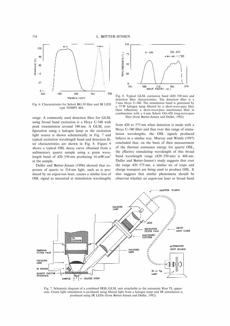
light source is shown schematically in Fig. 7 and
typical excitation wavelength band and detection ®l-
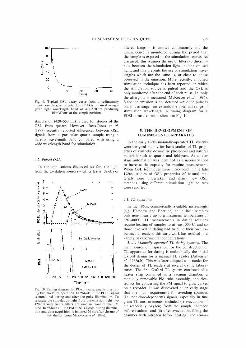
ter characteristics are shown in Fig. 8. Figure 9
shows a typical OSL decay curve obtained from a
sedimentary quartz sample using a green wave-
length band of 420±550 nm producing 16 mW/cm2
at the sample.
Duller and Bùtter-Jensen (1996) showed that ex-
posure of quartz to 514 nm light, such as is pro-
duced by an argon-ion laser, causes a similar loss of
OSL signal as measured at stimulation wavelengths
from 420 to 575 nm when detection is made with a
Hoya U-340 ®lter and that over this range of stimu-
lation wavelengths, the OSL signals produced
behave in a similar way. Murray and Wintle (1997)
concluded that, on the basis of their measurement
of the thermal assistance energy for quartz OSL,
the e�ective stimulating wavelength of this broad
band wavelength range (420±550 nm) is 468 nm.
Duller and Bùtter-Jensen's study suggests that over
the range 420±575 nm, a similar set of traps and
charge transport are being used to produce OSL. It
also suggests that similar phenomena should be
observed whether an argon-ion laser or broad band
Fig. 6. Characteristics for Schott BG-39 ®lter and IR LEDtype TEMPT 484.
Fig. 7. Schematic diagram of a combined IRSL/GLSL unit attachable to the automatic Risù TL appar-atus. Green light stimulation is produced using ®ltered light from a halogen lamp and IR stimulation is
produced using IR LEDs (from Bùtter-Jensen and Duller, 1992).
Fig. 8. Typical GLSL excitation band (420±550 nm) anddetection ®lter characteristics. The detection ®lter is a5 mm Hoya U-340. The stimulation band is generated bya 75 W halogen lamp ®ltered by a short-wave-pass ®lter(heat re¯ection), a short-wave-pass interference ®lter incombination with a 6 mm Schott GG-420 long-wave-pass
®lter (from Bùtter-Jensen and Duller, 1992).
L. BéTTER-JENSEN754
stimulation (420±550 nm) is used for studies of the
OSL from quartz. However, Rees-Jones et al.(1997) recently reported di�erences between OSLsignals from a particular quartz sample using a
narrow wavelength band compared with using awide wavelength band for stimulation.
4.2. Pulsed OSL
In the applications discussed so far, the lightfrom the excitation sources ± either lasers, diodes or
®ltered lamps ± is emitted continuously and theluminescence is monitored during the period that
the sample is exposed to the stimulation source. Asdiscussed, this requires the use of ®lters to discrimi-nate between the stimulation light and the emitted
light, and this prevents the use of stimulation wave-lengths which are the same as, or close to, thoseobserved in the emission. More recently, a pulsed
stimulation technique has been reported, in whichthe stimulation source is pulsed and the OSL isonly monitored after the end of each pulse, i.e. only
the afterglow is measured (McKeever et al., 1996).Since the emission is not detected while the pulse ison, this arrangement extends the potential range ofstimulation wavelength. A timing diagram for a
POSL measurement is shown in Fig. 10.
5. THE DEVELOPMENT OFLUMINESCENCE APPARATUS
In the early 1960s manually-operated TL systemswere designed mainly for basic studies of TL prop-erties of synthetic dosimetric phosphors and natural
materials such as quartz and feldspars. At a laterstage automation was identi®ed as a necessary toolto increase the capacity for routine measurement.
When OSL techniques were introduced in the late1980s, studies of OSL properties of natural ma-terials were undertaken and many new OSLmethods using di�erent stimulation light sources
were reported.
5.1. TL apparatus
In the 1960s, commercially available instruments(e.g. Harshaw and Eberline) could heat samples
only non-linearly up to a maximum temperature of350±4008C. TL measurements in dating routinesrequire heating of samples to at least 5008C, and so
those involved in dating had to build their own ex-perimental readers; this early work has resulted in avariety of experimental con®gurations.
5.1.1. Manually operated TL dating systems. Themain source of inspiration for the construction ofTL apparatus for dating is undoubtedly the initialOxford design for a manual TL reader (Aitken et
al., 1968a,b). This was later adopted as a model forthe design of TL readers at several dating labora-tories. The ®rst Oxford TL system consisted of a
heater strip contained in a vacuum chamber, amanually removable PM tube assembly, and elec-tronics for converting the PM signal to glow curves
on a recorder. It was discovered at an early stagethat the main requirement for avoiding spurious(i.e. non-dose-dependent) signals, especially in ®ne
grain TL measurements, included (i) evacuation ofair (especially oxygen) from the sample chamberbefore readout, and (ii) after evacuation, ®lling thechamber with nitrogen before heating. The atmos-
Fig. 9. Typical OSL decay curve from a sedimentaryquartz sample given a beta dose of 2 Gy obtained using agreen light wavelength band of 420±550 nm producing
16 mW/cm2 at the sample position.
Fig. 10. Timing diagram for POSL measurements illustrat-ing two modes of operation. In ``Mode I'' the POSL signalis monitored during and after the pulse illumination. Toseparate the stimulation light from the emission light two420-nm interference ®lters are used in front of the PMtube. In ``Mode II'' the PM tube is closed during illumina-tion and data acquisition is initiated 20 ms after closure of
the shutter (from McKeever et al., 1996).
LUMINESCENCE TECHNIQUES 755
phere was controlled using a vacuum gauge and
manual valves for vacuum and nitrogen. TheOxford concept was later taken up and modi®ed tomeet special requirements e.g. by Unfried and Vana
(1982) who built a system based on photon count-ing and heating samples up to 5008C in any atmos-phere. Visocekas (1979) and Huntley et al. (1988)
constructed their own manually operated exper-imental TL readers which were used to study TL at
low and constant temperatures (isothermal decay)and TL emission spectra, respectively. Vana et al.(1988) developed a manual TL dating system that
allowed heating up to 7008C in any atmosphere andcollection of measurements on a personal computer.Brou and Valladas (1975) constructed a special high
temperature TL glow-oven with cooled heater term-inals which allowed for heating up to 8008C. Thiswas used to study the high temperature peaks ofvolcanic materials (Valladas and Gillot, 1978). Par-allel to the development work carried out in di�er-
ent laboratories the Daybreak and Littlemorecompanies introduced commercially availablemanually-operated TL systems based on a glow-
oven for single measurements and photon countingtechniques, speci®cally intended for dating appli-
cations.5.1.2. Automatic TL dating apparatus. In the late
1960s the demand on TL dating laboratories to rou-
tinely carry out a large number of measurementsaccentuated the need for equipment with automaticchanging of samples. An automatic TL reader,
using a planchette sample changer capable ofmeasuring 12 samples in sequence, was ®rst devel-oped at Risù (Bùtter-Jensen and Bechmann, 1968).
With the establishment of the Nordic Laboratoryfor TL Dating at Risù in 1977, microprocessor and
PC-controlled 24-sample automatic TL readers weredeveloped for routine dating of a large number ofsamples (Bùtter-Jensen and Bundgaard, 1978; Bùt-
ter-Jensen and Mejdahl, 1980; Bùtter-Jensen et al.,1983). Bùtter-Jensen (1988) described an automaticTL system made up of a software-controlled 24-
sample glow-oven/sample changer, and one or twobeta irradiators, all contained in a vacuum
chamber. The automated Risù TL reader (modelTL-DA-8) ®rst became commercially available in1983 and some years later the Daybreak and Little-
more companies constructed 20-sample and 24-sample automatic TL readers, respectively, buildingon the concept of the initial Risù design (see Sec-
tion 6). Baili� and Younger (1988) built a 24-sample microprocessor-based semi-automatic TL
apparatus, designed mainly for research, that incor-porated an on-plate beta irradiator and automaticcontrol of vacuum and nitrogen atmospheres. At a
later stage Galloway (1991) produced a 40-samplesystem and Henzinger et al. (1994) reported a fullyautomated 60-sample automatic TL reader system
developed at Atominstitut der OÈ sterreichischen Uni-versitaÈ t, Vienna. In addition to the sample changer,
this system incorporated a beta irradiator position,an alpha irradiator position, a preheat position and
a TL readout position. More recently Valladas etal. (1996) reported a simple automatic TL appar-atus that can accommodate 16 samples. The turnta-
ble of this system pushes the samples in sequenceonto a hotplate, and heating is performed withoutlifting the samples from the turntable.
5.2. OSL apparatus
Huntley et al. (1985) ®rst showed that 514 nmlaser light could be used to measure dose-dependent
OSL from quartz. However, the expense of estab-lishing such laser facilities meant that this techniquewould be available only in a very limited number of
laboratories. As a consequence, the observation byHuÈ tt et al. (1988) that OSL in feldspars could bestimulated with infrared wavelengths was of import-
ance. This made possible the use of inexpensive andreadily available IR light emitting diodes (LEDs) asthe stimulation light source. As a result, IRSLrapidly became the most popular dating tool. Green
LEDs give orders of magnitude less power than IRLEDs, and so the best alternative to lasers for vis-ible light stimulation was the light spectra obtained
from heavy ®ltered halogen or xenon lamps (e.g.Bùtter-Jensen and Duller, 1992).In OSL measurements, preheating of samples is
normally required to remove charge from shallowtraps prior to light stimulation (e.g. Huntley et al.,1996). This can either be done in an oven kept at a
selected temperature or for short duration preheat,as part of the measurement cycle in the reader. Therate of decay of OSL, and the degree of bleaching,have also been shown to depend on the sample tem-
perature at which the OSL measurement is carriedout. For instance Wintle and Murray (1997) rec-ommend OSL of quartz at 1258C to remove inter-
action with the 1108C TL peak. Therefore, it isimportant that OSL apparatus be equipped with aheating facility for both preheating and readout at
elevated temperature. Also, since erasure of theOSL signal still leaves most of the TL signal unaf-fected, it is possible to measure ®rst OSL and thenTL on the same sample as suggested by Godfrey-
Smith et al. (1988) and demonstrated by Bùtter-Jensen and Duller (1992).
5.2.1. IRSL apparatus. Poolton and Baili� (1989),
Spooner et al. (1990) and Bùtter-Jensen et al. (1991)described the use of IR LEDs for IR stimulation offeldspars and obtained very promising results. Bùt-
ter-Jensen et al. (1991) constructed an IRSL add-onunit to be mounted directly between the PM tubeassembly and the glow-oven of the automated Risù
TL apparatus (see Fig. 5). Thirty-two IR LEDswere arranged in two concentric rings. IRSLemitted vertically through the ring of diodes wasthen measured with the same PM as used for the
L. BéTTER-JENSEN756
TL measurements. A BG-39 detection ®lter rejectedthe scattered IR light. The total power delivered to
the sample using GaA1/As IR LEDs (TEMPT 484,880 R 80 nm) was measured as 40 mW/cm2 at adiode current of 50 mA. A feedback servo system
served to stabilise the current through the LEDs(see Fig. 5).Spooner and Questiaux (1990) used an infrared
light spectrum ®ltered from a xenon lamp for opti-cal stimulation of feldspar samples. The use of anexcimer dye laser and an IR diode laser for IRSL
dating was described by HuÈ tt and Jaek (1989,1990).5.2.2. GLSL apparatus. The demand for OSL dat-
ing of quartz and an alternative to laser stimulation
led to the development of OSL systems based ongreen light LEDs or green light wavelength bands®ltered from incandescent broad band lamps. Gal-
loway (1993, 1994) described initial investigationsinto the use of green light LEDs for stimulation ofquartz and feldspars. The system was based on a
ring of 16 green LEDs, type TLMP 7513 with peakemission at 565 nm, illuminating the sample. Therelatively small power that could be delivered to the
sample and the heavy ®ltering of the photomulti-plier cathode necessary to avoid stray light from theLED emission band resulted in slowly decayingOSL curves that required readout times in the order
of 2000 s to give useful signals for dose assessment.However, these initial investigations into greenLEDs for OSL dosimetry provided a good basis for
investigations of new more powerful green LEDsbeing continuously developed (see Section 6).
Bùtter-Jensen and Duller (1992) developed a
compact green light OSL (GLSL) system based onthe light emitted from a simple low-power halogenlamp. This lamp provides a broad band light sourcefrom which a suitable stimulation spectrum can be
selected using optical ®lters. The stimulation unitalso incorporated a ring of IR LEDs at a short dis-tance from the sample. The GLSL/IRSL unit was
designed to be mounted onto the automated RisùTL apparatus, thus providing ¯exible combinedIRSL/GLSL/TL features. A low-power (75 W)
tungsten halogen lamp ®ltered to produce a stimu-lation wavelength band from 420±550 nm delivereda power of 16 mW/cm2 to the sample. The OSL sig-
nals obtained from quartz were observed to decayat the same rate as that observed using an argonlaser (514 nm) delivering 50 mW/cm2 at the sample,presumably because of the higher energies present
in the broad band from the ®ltered halogen lamp.The principle of the GLSL unit is shown in Fig. 7.
5.3. Commercially available TL/OSL systems
Three main distributers of TL/OSL dating equip-ment are: Daybreak Nuclear and Medical Systems,USA, ELSEC-Littlemore Scienti®c Engineering
Company, UK, and Risù National Laboratory,Denmark.
The Daybreak instrument programme includes astandard 20-sample automatic TL reader (model1100) using an on-board computer and serial inter-
face to a host computer. The samples are moved bya sweep arm from the sample turntable to the heat-ing/reading position and back. An upgraded model
1150 TL reader is available with a capacity of 57samples achieved by vertically stacking three 20-sample platters. Various OSL attachments are avail-
able based on xenon and halogen lamps. A compact®bre optic illuminator attachment was recentlyreported by Bortolot (1997) (see Section 6), and anew OSL reader design (without TL facilities) based
on 60-sample capacity is under development.The Littlemore Company has two standard auto-
mated luminescence dating instruments available.
One is a 24-sample automated TL reader (withoutOSL attachments) and the other is a 64-sampleoptical dating system (without TL facilities) which
is available with either IR LED stimulation or vis-ible light stimulation using a ®ltered lamp module.An attachable beta irradiator is provided for the
automated TL reader.Risù National Laboratory provides an automatic
combined TL/IRSL/GLSL dating system that canaccommodate di�erent sample turntables containing
24, 36 or 48 samples, respectively. The most recentmodel of OSL accessory is a unit containing IRLEDs in close proximity to the sample, and green
light stimulation from long-life (2000 h) high-power(150 W) halogen and xenon lamps and a liquidlightguide to provide high transmission. A close
sample-to-detector spacing has resulted in a signi®-cantly enhanced OSL sensitivity (see Section 6). Asoftware-controlled beta irradiator attachment forin situ irradiations of samples is also provided. A
new sequence software has also signi®cantlyextended the ¯exibility and measurement capabili-ties.
5.4. Development of specialised OSL equipment
5.4.1. OSL equipment for sediment dating and ret-rospective accident dosimetry. Intensive dating of
thick sediment deposits can be very time-consum-ing, and often provides little information that couldnot be obtained from a few carefully selected
samples. Changes in the stratigraphy relating to, forinstance, breaks in the deposition history will showup as discontinuities in the apparent radiation dose
in the sediment either as a result of di�erent age ordi�erent bleaching. As a consequence, it is desirableto be able to rapidly assess the luminescence prop-
erties of the sediment at regular intervals down asection, preferably in the ®eld. Poolton et al. (1994)described a compact portable computer-controlledOSL apparatus that allows the measurement of in-
LUMINESCENCE TECHNIQUES 757
frared OSL of sediments in the ®eld, whether in the
form of loose grains or compressed pellets. The unit
uses IR LEDs for excitation with bleaching and
IRSL regeneration provided by cold gas discharge
lamps.
When several tens of metres of sediment core are
available for study, it is often di�cult to decide
exactly where to select material for detailed analysis
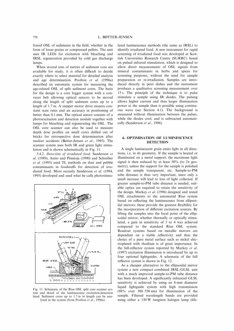
and age determination. Poolton et al. (1996a)
described an automatic system for measuring the
age-related OSL of split sediment cores. The basis
for the design is a core logger system with a con-
veyer belt allowing optical sensors to be moved
along the length of split sediment cores up to a
length of 1.7 m. A stepper motor drive ensures con-
stant scan rates and an accuracy in positioning of
better than 0.1 mm. The optical sensor consists of a
photoexcitation and detection module together with
lamps for bleaching and regenerating the OSL. The
OSL core scanner can also be used to measure
depth dose pro®les on small cores drilled out of
bricks for retrospective dose determination after
nuclear accidents (Bùtter-Jensen et al., 1995). The
scanner system uses both IR and green light stimu-
lation and is shown schematically in Fig. 11.
5.4.2. Detection of irradiated food. Sanderson et
al. (1989), Autio and Pinnioja (1990) and Schreiber
et al. (1993) used TL methods on dust and pebble
contaminants in foodstu�s for detection of irra-
diated food. More recently Sanderson et al. (1994,
1995) developed and used what he calls photostimu-
lated luminescence methods (the same as IRSL) toidentify irradiated food. A new instrument for rapid
screening of irradiated food was developed at Scot-tish Universities Research Centre (SURRC) basedon pulsed infrared stimulation, which is designed to
allow direct measurements of OSL signals frommineral contaminants in herbs and spices forscreening purposes, without the need for sample
preparation or re-irradiation. Samples are intro-duced directly in petri dishes and the instrumentproduces a qualitative screening measurement over
15 s. The principle of the technique is to pulsestimulate a sample using IR diodes. The pulsingallows higher current and thus larger illuminationpower at the sample than is possible using continu-
ous wave (see Section 4.1). The background ismeasured without illumination between the pulses,while the diodes cool, and is subtracted automati-
cally (Sanderson et al., 1996).
6. OPTIMISATION OF LUMINESCENCEDETECTION
A single luminescent grain emits light in all direc-tions, i.e. in 4p geometry. If the sample is heated orilluminated on a metal support, the maximum light
signal is then reduced by at least 50% (to 2p geo-metry), unless the support for the sample is polishedand the sample transparent, etc. Sample-to-PM
tube distance is thus very important, since only asmall increase will lead to loss of light collected. Ifgreater sample-to-PM tube distance is needed, suit-
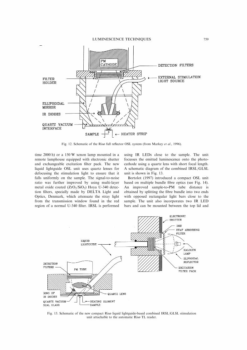
able optics are required to retain the sensitivity ofthe design. Markey et al. (1996) designed and testedOSL attachments to the automated Risù systembased on re¯ecting the luminescence from ellipsoi-
dal mirrors; these provide the greatest ¯exibility forthe incorporation of di�erent excitation sources. Bylifting the samples into the focal point of the ellip-
soidal mirror, whether thermally or optically stimu-lated, a gain in sensitivity of 3 to 4 was achievedcompared to the standard Risù OSL system.
Readout systems based on metallic mirrors aredependent on a stable re¯ectivity and thus thechoice of a pure metal surface such as nickel elec-troplated with rhodium is of great importance. In
the full-re¯ector system reported by Markey et al.(1997) excitation illuminaton is introduced by up tofour optional lightguides. A schematic of the full
re¯ector system is shown in Fig. 12.As a cheaper alternative to the ellipsoidal mirror
system a new compact combined IRSL/GLSL unit
with a much improved sample-to-PM tube distancehas been developed. A signi®cantly enhanced GLSLsensitivity is achieved by using an 8-mm diameter
liquid lightguide system with high transmission(98% over 380±550 nm) for illumination of thesample. Filtered wavelength bands are providedusing either a 150 W tungsten halogen lamp (life-
Fig. 11. Schematic of the Risù OSL split core scanner sys-tem and detail of the luminescence excitation/detectionhead. Sediment cores up to 1.7 m in length can be ana-
lysed in the system (from Poolton et al., 1996a).
L. BéTTER-JENSEN758
time 2000 h) or a 150 W xenon lamp mounted in a
remote lamphouse equipped with electronic shutter
and exchangeable excitation ®lter pack. The new
liquid lightguide OSL unit uses quartz lenses for
defocusing the stimulation light to ensure that it
falls uniformly on the sample. The signal-to-noise
ratio was further improved by using multi-layer
metal oxide coated (ZrO2/SiO2) Hoya U-340 detec-
tion ®lters, specially made by DELTA Light and
Optics, Denmark, which attenuate the stray light
from the transmission window found in the red
region of a normal U-340 ®lter. IRSL is performed
using IR LEDs close to the sample. The unit
focusses the emitted luminescence onto the photo-
cathode using a quartz lens with short focal length.
A schematic diagram of the combined IRSL/GLSL
unit is shown in Fig. 13.
Bortolot (1997) introduced a compact OSL unit
based on multiple bundle ®bre optics (see Fig. 14).
An improved sample-to-PM tube distance is
obtained by splitting the ®bre bundle into two ends
with opposed rectangular light bars close to the
sample. The unit also incorporates two IR LED
bars and can be mounted between the top lid and
Fig. 12. Schematic of the Risù full re¯ector OSL system (from Markey et al., 1996).
Fig. 13. Schematic of the new compact Risù liquid lightguide-based combined IRSL/GLSL stimulationunit attachable to the automatic Risù TL reader.
LUMINESCENCE TECHNIQUES 759
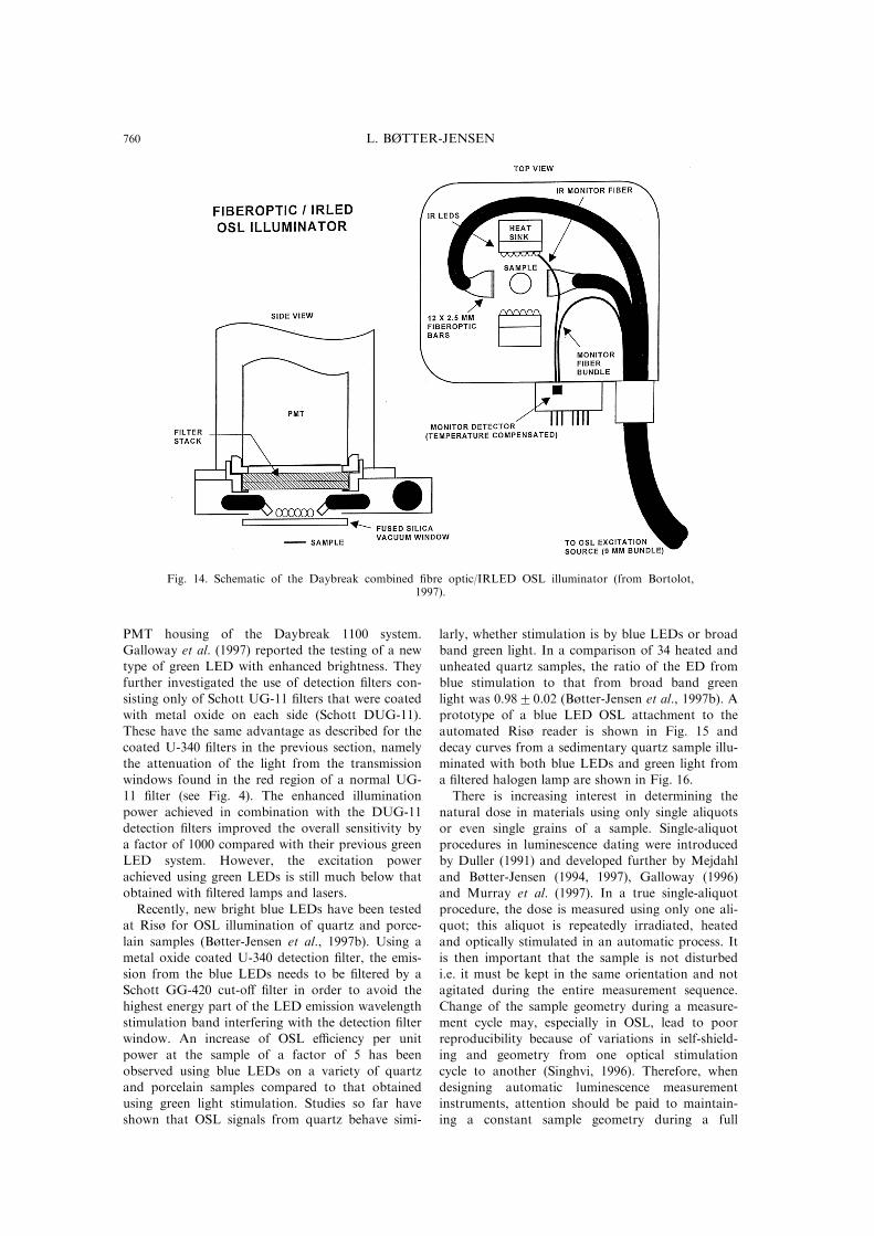
PMT housing of the Daybreak 1100 system.
Galloway et al. (1997) reported the testing of a new
type of green LED with enhanced brightness. They
further investigated the use of detection ®lters con-
sisting only of Schott UG-11 ®lters that were coated
with metal oxide on each side (Schott DUG-11).
These have the same advantage as described for the
coated U-340 ®lters in the previous section, namely
the attenuation of the light from the transmission
windows found in the red region of a normal UG-
11 ®lter (see Fig. 4). The enhanced illumination
power achieved in combination with the DUG-11
detection ®lters improved the overall sensitivity by
a factor of 1000 compared with their previous green
LED system. However, the excitation power
achieved using green LEDs is still much below that
obtained with ®ltered lamps and lasers.
Recently, new bright blue LEDs have been tested
at Risù for OSL illumination of quartz and porce-
lain samples (Bùtter-Jensen et al., 1997b). Using a
metal oxide coated U-340 detection ®lter, the emis-
sion from the blue LEDs needs to be ®ltered by a
Schott GG-420 cut-o� ®lter in order to avoid the
highest energy part of the LED emission wavelength
stimulation band interfering with the detection ®lter
window. An increase of OSL e�ciency per unit
power at the sample of a factor of 5 has been
observed using blue LEDs on a variety of quartz
and porcelain samples compared to that obtained
using green light stimulation. Studies so far have
shown that OSL signals from quartz behave simi-
larly, whether stimulation is by blue LEDs or broad
band green light. In a comparison of 34 heated and
unheated quartz samples, the ratio of the ED from
blue stimulation to that from broad band green
light was 0.9820.02 (Bùtter-Jensen et al., 1997b). A
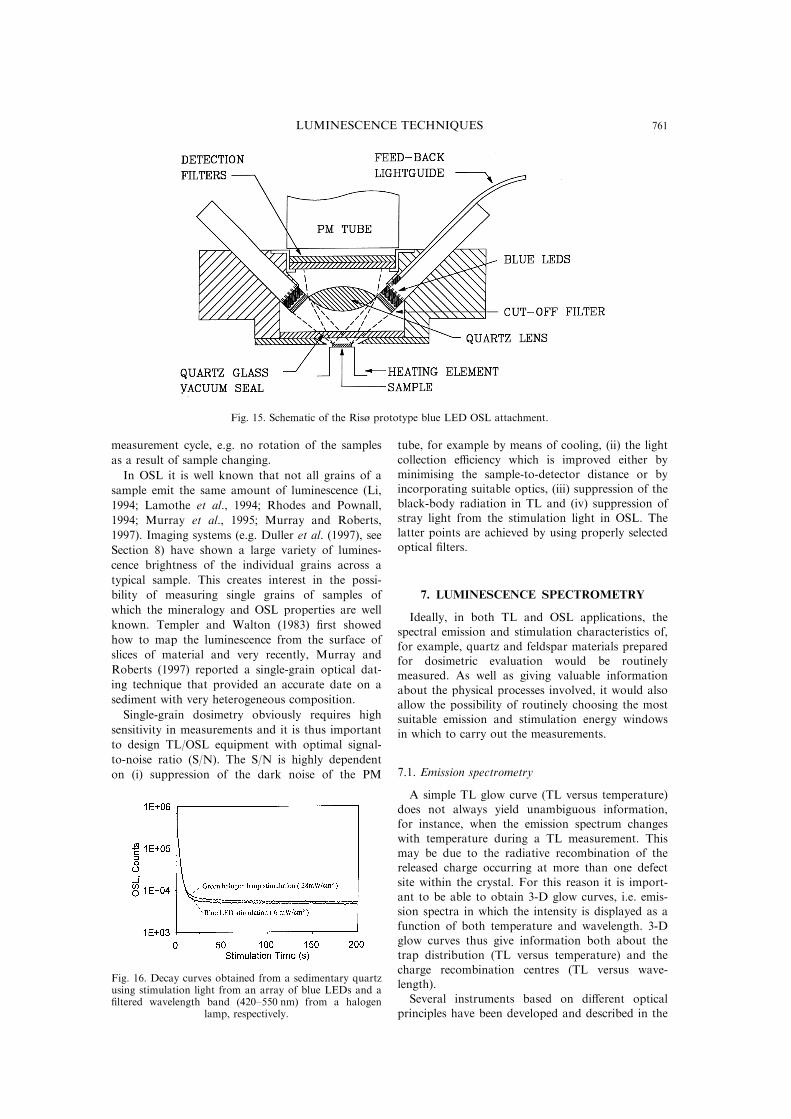
prototype of a blue LED OSL attachment to the
automated Risù reader is shown in Fig. 15 and
decay curves from a sedimentary quartz sample illu-
minated with both blue LEDs and green light from
a ®ltered halogen lamp are shown in Fig. 16.
There is increasing interest in determining the
natural dose in materials using only single aliquots
or even single grains of a sample. Single-aliquot
procedures in luminescence dating were introduced
by Duller (1991) and developed further by Mejdahl
and Bùtter-Jensen (1994, 1997), Galloway (1996)
and Murray et al. (1997). In a true single-aliquot
procedure, the dose is measured using only one ali-
quot; this aliquot is repeatedly irradiated, heated
and optically stimulated in an automatic process. It
is then important that the sample is not disturbed
i.e. it must be kept in the same orientation and not
agitated during the entire measurement sequence.
Change of the sample geometry during a measure-
ment cycle may, especially in OSL, lead to poor
reproducibility because of variations in self-shield-
ing and geometry from one optical stimulation
cycle to another (Singhvi, 1996). Therefore, when
designing automatic luminescence measurement
instruments, attention should be paid to maintain-
ing a constant sample geometry during a full
Fig. 14. Schematic of the Daybreak combined ®bre optic/IRLED OSL illuminator (from Bortolot,1997).
L. BéTTER-JENSEN760
measurement cycle, e.g. no rotation of the samples
as a result of sample changing.
In OSL it is well known that not all grains of a
sample emit the same amount of luminescence (Li,
1994; Lamothe et al., 1994; Rhodes and Pownall,
1994; Murray et al., 1995; Murray and Roberts,
1997). Imaging systems (e.g. Duller et al. (1997), see
Section 8) have shown a large variety of lumines-
cence brightness of the individual grains across a
typical sample. This creates interest in the possi-
bility of measuring single grains of samples of
which the mineralogy and OSL properties are well
known. Templer and Walton (1983) ®rst showed
how to map the luminescence from the surface of
slices of material and very recently, Murray and
Roberts (1997) reported a single-grain optical dat-
ing technique that provided an accurate date on a
sediment with very heterogeneous composition.
Single-grain dosimetry obviously requires high
sensitivity in measurements and it is thus important
to design TL/OSL equipment with optimal signal-
to-noise ratio (S/N). The S/N is highly dependent
on (i) suppression of the dark noise of the PM
tube, for example by means of cooling, (ii) the light
collection e�ciency which is improved either byminimising the sample-to-detector distance or byincorporating suitable optics, (iii) suppression of the
black-body radiation in TL and (iv) suppression ofstray light from the stimulation light in OSL. Thelatter points are achieved by using properly selectedoptical ®lters.
7. LUMINESCENCE SPECTROMETRY
Ideally, in both TL and OSL applications, thespectral emission and stimulation characteristics of,
for example, quartz and feldspar materials preparedfor dosimetric evaluation would be routinelymeasured. As well as giving valuable information
about the physical processes involved, it would alsoallow the possibility of routinely choosing the mostsuitable emission and stimulation energy windows
in which to carry out the measurements.
7.1. Emission spectrometry
A simple TL glow curve (TL versus temperature)does not always yield unambiguous information,for instance, when the emission spectrum changes
with temperature during a TL measurement. Thismay be due to the radiative recombination of thereleased charge occurring at more than one defect
site within the crystal. For this reason it is import-ant to be able to obtain 3-D glow curves, i.e. emis-sion spectra in which the intensity is displayed as a
function of both temperature and wavelength. 3-Dglow curves thus give information both about thetrap distribution (TL versus temperature) and the
charge recombination centres (TL versus wave-length).Several instruments based on di�erent optical
principles have been developed and described in the
Fig. 15. Schematic of the Risù prototype blue LED OSL attachment.
Fig. 16. Decay curves obtained from a sedimentary quartzusing stimulation light from an array of blue LEDs and a®ltered wavelength band (420±550 nm) from a halogen
lamp, respectively.
LUMINESCENCE TECHNIQUES 761
literature. Dispersive rapid scanning systems based
on di�raction gratings were described in the early
1970s by Harris and Jackson (1970) and Mattern et
al. (1971). Methods using optical ®lters have also
been employed: Baili� et al. (1977) reported a rapid
scanning TL spectrometer based on successive
narrow band interference ®lters of 20 nm bandwidth
®xed on a common turntable; Bùtter-Jensen et al.
(1994b) developed a compact scanning monochro-
mator based on a moveable variable interference ®l-
ter. Huntley et al. (1988) built a spectrometer based
on a custom-made concave holographic grating in
connection with a microchannel plate PM tube and
image converter to obtain wavelength-resolved spec-
tra of a variety of mineral samples. A sensitive spec-
trometer based on Fourier transform spectroscopy
which o�ers high aperture for light collection and
continuous detection at all wavelengths in the range
350±600 nm was developed by Prescott et al. (1988).
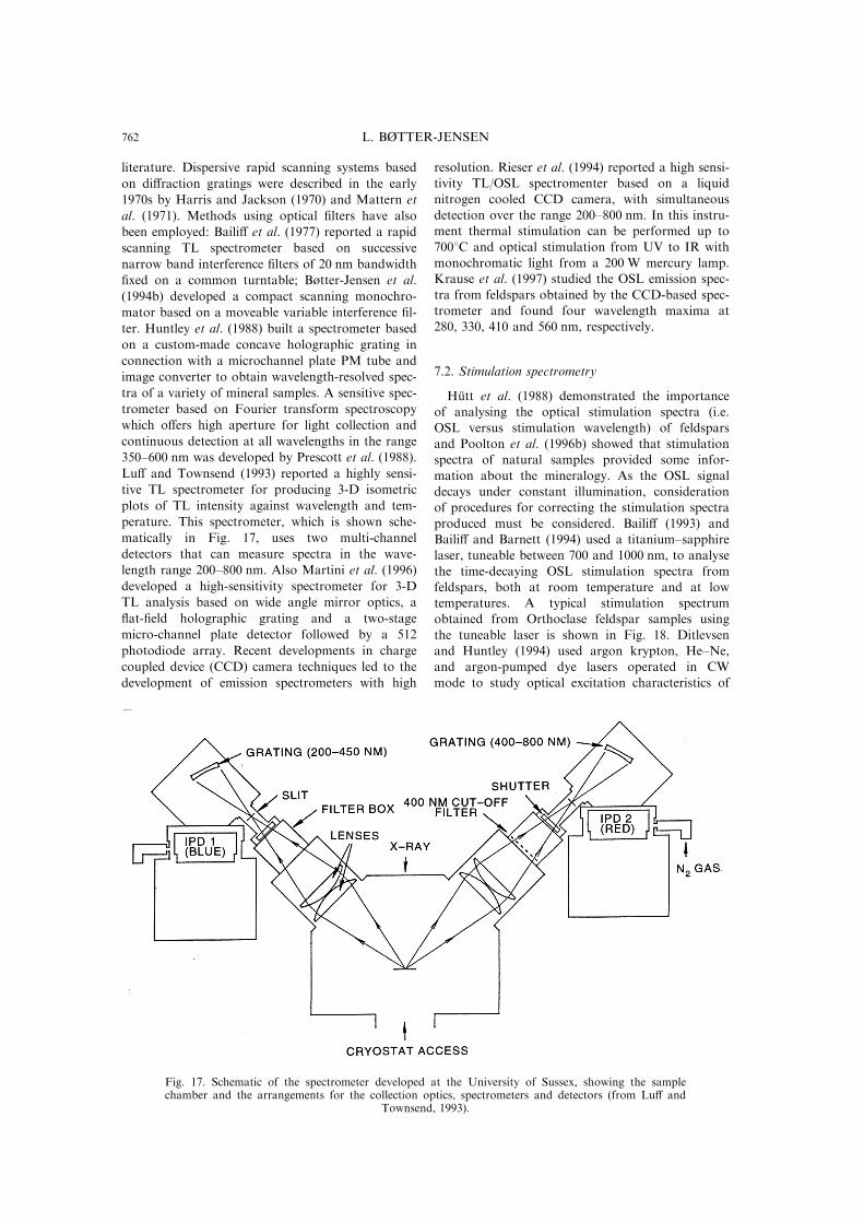
Lu� and Townsend (1993) reported a highly sensi-
tive TL spectrometer for producing 3-D isometric
plots of TL intensity against wavelength and tem-
perature. This spectrometer, which is shown sche-
matically in Fig. 17, uses two multi-channel
detectors that can measure spectra in the wave-
length range 200±800 nm. Also Martini et al. (1996)
developed a high-sensitivity spectrometer for 3-D
TL analysis based on wide angle mirror optics, a
¯at-®eld holographic grating and a two-stage
micro-channel plate detector followed by a 512
photodiode array. Recent developments in charge
coupled device (CCD) camera techniques led to the
development of emission spectrometers with high
resolution. Rieser et al. (1994) reported a high sensi-tivity TL/OSL spectromenter based on a liquid
nitrogen cooled CCD camera, with simultaneousdetection over the range 200±800 nm. In this instru-ment thermal stimulation can be performed up to
7008C and optical stimulation from UV to IR withmonochromatic light from a 200 W mercury lamp.Krause et al. (1997) studied the OSL emission spec-
tra from feldspars obtained by the CCD-based spec-trometer and found four wavelength maxima at280, 330, 410 and 560 nm, respectively.
7.2. Stimulation spectrometry
HuÈ tt et al. (1988) demonstrated the importanceof analysing the optical stimulation spectra (i.e.
OSL versus stimulation wavelength) of feldsparsand Poolton et al. (1996b) showed that stimulationspectra of natural samples provided some infor-
mation about the mineralogy. As the OSL signaldecays under constant illumination, considerationof procedures for correcting the stimulation spectra
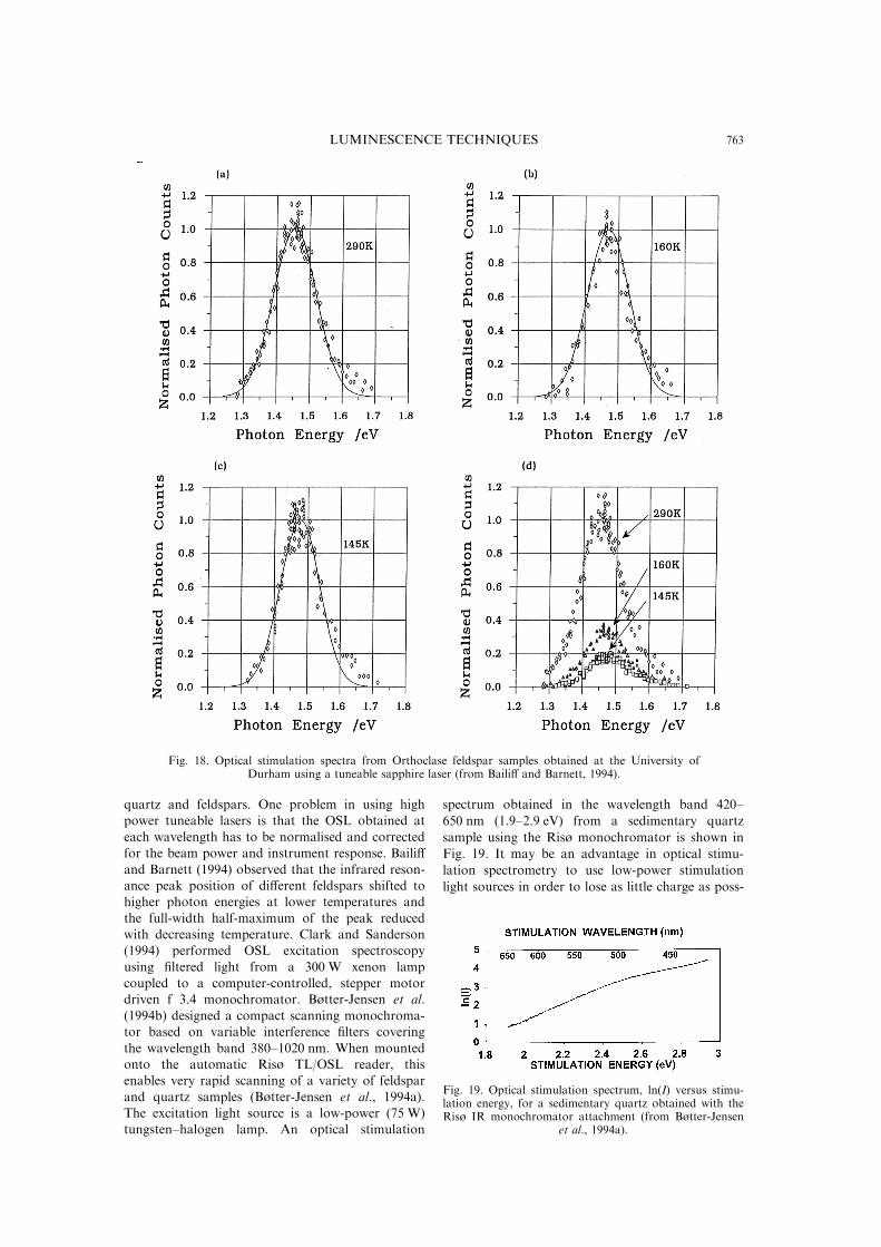
produced must be considered. Baili� (1993) andBaili� and Barnett (1994) used a titanium±sapphirelaser, tuneable between 700 and 1000 nm, to analyse
the time-decaying OSL stimulation spectra fromfeldspars, both at room temperature and at lowtemperatures. A typical stimulation spectrumobtained from Orthoclase feldspar samples using
the tuneable laser is shown in Fig. 18. Ditlevsenand Huntley (1994) used argon krypton, He±Ne,and argon-pumped dye lasers operated in CW
mode to study optical excitation characteristics of
Fig. 17. Schematic of the spectrometer developed at the University of Sussex, showing the samplechamber and the arrangements for the collection optics, spectrometers and detectors (from Lu� and
Townsend, 1993).
L. BéTTER-JENSEN762
quartz and feldspars. One problem in using highpower tuneable lasers is that the OSL obtained at
each wavelength has to be normalised and correctedfor the beam power and instrument response. Baili�
and Barnett (1994) observed that the infrared reson-ance peak position of di�erent feldspars shifted tohigher photon energies at lower temperatures and
the full-width half-maximum of the peak reducedwith decreasing temperature. Clark and Sanderson(1994) performed OSL excitation spectroscopy
using ®ltered light from a 300 W xenon lampcoupled to a computer-controlled, stepper motordriven f 3.4 monochromator. Bùtter-Jensen et al.
(1994b) designed a compact scanning monochroma-tor based on variable interference ®lters covering
the wavelength band 380±1020 nm. When mountedonto the automatic Risù TL/OSL reader, thisenables very rapid scanning of a variety of feldspar
and quartz samples (Bùtter-Jensen et al., 1994a).The excitation light source is a low-power (75 W)tungsten±halogen lamp. An optical stimulation
spectrum obtained in the wavelength band 420±
650 nm (1.9±2.9 eV) from a sedimentary quartz
sample using the Risù monochromator is shown in
Fig. 19. It may be an advantage in optical stimu-
lation spectrometry to use low-power stimulation
light sources in order to lose as little charge as poss-
Fig. 18. Optical stimulation spectra from Orthoclase feldspar samples obtained at the University ofDurham using a tuneable sapphire laser (from Baili� and Barnett, 1994).
Fig. 19. Optical stimulation spectrum, ln(I) versus stimu-lation energy, for a sedimentary quartz obtained with theRisù IR monochromator attachment (from Bùtter-Jensen
et al., 1994a).
LUMINESCENCE TECHNIQUES 763
ible during OSL readout. Then corrections areneeded only for the intensity spectrum of the excit-
ing lamp since the trapped charge evicted during arapid scan can be reduced to typically 10%.
8. LUMINESCENCE IMAGING
The majority of luminescence measurements are
made using PM tubes with bialkali photocathodes.These devices o�er high sensitivity in the blue andnear ultra-violet. However, the PM tube used for
such measurements integrates the luminescence sig-nal from the entire sample and gives no indicationof any spatial variation in luminescence intensity
within a sample. Duller (1991) initiated the develop-ment of a technique for measuring the dose in asingle aliquot. The study of luminescence signalseven from individual grains is likely to become im-
portant, especially for the understanding of sourcesof scatter from one aliquot to another, to separatemineral-speci®c luminescence signals from poly-
mineralic samples, and in the development ofmethods for single grain dosimetry (e.g. Murrayand Roberts, 1997). Single grain dosimetry, how-
ever, would be far more practical if many grainsmounted on the same aliquot could be irradiated,preheated and measured simultaneously and thenusing an imaging system to separate the lumines-
cence signals from the individual grains. Hashimoto
et al. (1986) developed techniques for imaging TL
signals from sliced rock samples and quartz from
beach sands using extremely high-sensitivity colour
®lms. At a later stage Hashimoto et al. (1989) and
Kawamura and Hashimoto (1995) converted the
TL colour images (TLCI) from photographic form
into a computer process that made it possible to
obtain quantitative information and to distinguish
for example between blue and red coloured grains.
Hashimoto et al. (1995) obtained OSL images of
some X- and gamma-irradiated granite slices using
photon detection through a 570 nm bandpass ®lter
with diode-laser excitation of 910 nm. Several other
laboratories have attempted to develop systems
capable of imaging the luminescence signal from a
sample. Recently three groups have used imaging
photon detectors (IPDs), two at University of
Oxford (Smith et al., 1991; McFee and Tite, 1994)
and another at University of Utah, Salt Lake City
(Berggraaf and Haskell, 1994). These instruments
retain the high sensitivity of a PM tube, but are
rather expensive and di�cult to operate. The devel-
opment of solid state imaging systems based on
charge coupled device (CCD) technology o�ers an
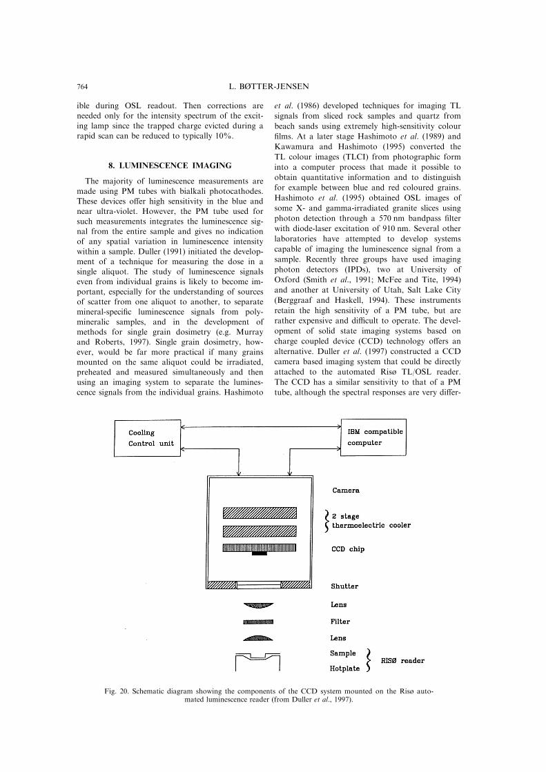
alternative. Duller et al. (1997) constructed a CCD
camera based imaging system that could be directly
attached to the automated Risù TL/OSL reader.
The CCD has a similar sensitivity to that of a PM
tube, although the spectral responses are very di�er-
Fig. 20. Schematic diagram showing the components of the CCD system mounted on the Risù auto-mated luminescence reader (from Duller et al., 1997).
L. BéTTER-JENSEN764
ent. This CCD system is capable of detecting natu-ral luminescence signals with a spatial resolution of
as high as 17 mm. Temperature-resolved TL signalsand time-resolved OSL curves can be obtainedusing software and the luminescence signals gener-
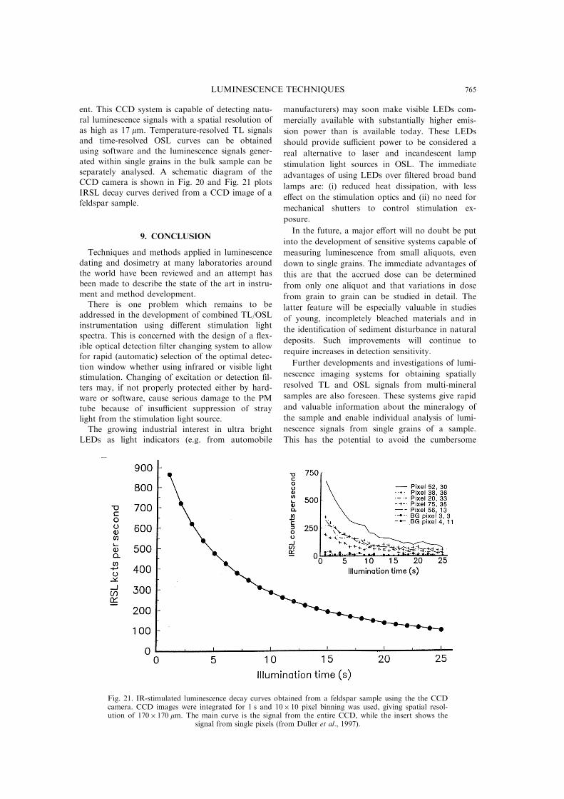
ated within single grains in the bulk sample can beseparately analysed. A schematic diagram of theCCD camera is shown in Fig. 20 and Fig. 21 plots
IRSL decay curves derived from a CCD image of afeldspar sample.
9. CONCLUSION
Techniques and methods applied in luminescence
dating and dosimetry at many laboratories aroundthe world have been reviewed and an attempt hasbeen made to describe the state of the art in instru-
ment and method development.There is one problem which remains to be
addressed in the development of combined TL/OSL
instrumentation using di�erent stimulation lightspectra. This is concerned with the design of a ¯ex-ible optical detection ®lter changing system to allowfor rapid (automatic) selection of the optimal detec-
tion window whether using infrared or visible lightstimulation. Changing of excitation or detection ®l-ters may, if not properly protected either by hard-
ware or software, cause serious damage to the PMtube because of insu�cient suppression of straylight from the stimulation light source.
The growing industrial interest in ultra brightLEDs as light indicators (e.g. from automobile
manufacturers) may soon make visible LEDs com-
mercially available with substantially higher emis-
sion power than is available today. These LEDs
should provide su�cient power to be considered a
real alternative to laser and incandescent lamp
stimulation light sources in OSL. The immediate
advantages of using LEDs over ®ltered broad band
lamps are: (i) reduced heat dissipation, with less
e�ect on the stimulation optics and (ii) no need for
mechanical shutters to control stimulation ex-
posure.
In the future, a major e�ort will no doubt be put
into the development of sensitive systems capable of
measuring luminescence from small aliquots, even
down to single grains. The immediate advantages of
this are that the accrued dose can be determined
from only one aliquot and that variations in dose
from grain to grain can be studied in detail. The
latter feature will be especially valuable in studies
of young, incompletely bleached materials and in
the identi®cation of sediment disturbance in natural
deposits. Such improvements will continue to
require increases in detection sensitivity.
Further developments and investigations of lumi-
nescence imaging systems for obtaining spatially
resolved TL and OSL signals from multi-mineral
samples are also foreseen. These systems give rapid
and valuable information about the mineralogy of
the sample and enable individual analysis of lumi-
nescence signals from single grains of a sample.
This has the potential to avoid the cumbersome
Fig. 21. IR-stimulated luminescence decay curves obtained from a feldspar sample using the the CCDcamera. CCD images were integrated for 1 s and 10� 10 pixel binning was used, giving spatial resol-ution of 170�170 mm. The main curve is the signal from the entire CCD, while the insert shows the
signal from single pixels (from Duller et al., 1997).
LUMINESCENCE TECHNIQUES 765
mechanical and chemical separation processes pre-sently required.
AcknowledgementsÐThe author has drawn heavily onpublications kindly supplied by a number of authors whohave contributed to the development of a wide variety ofluminescence techniques and methods. However, havingbeen in the ®eld of developing luminescence instrumentsand methods for many years, the author of the presentpaper is inevitably biased towards the work carried out atRisù and I apologise to those who might feel that theirwork has not been given adequate attention.The author isgrateful to Andrew Murray and Vagn Mejdahl for goingthrough the manuscript and for helpful comments anddiscussions.The development of the new Risù OSL unitdescribed was partly funded by the EU project ``DoseReconstruction''.
REFERENCES
Aitken, M. J., Tite, M. S. and Reid, J. (1964)Thermoluminescent dating of ancient ceramics.Nature 202, 1032±1033.
Aitken, M. J., Zimmerman, D. W. and Fleming, S.J. (1968a) Thermoluminescent dating of ancient pot-tery. Nature 219, 442±444.
Aitken, M. J., Alldred, J. C. and Thompson, J. (1968b) Aphoton-ratemeter system for low-level thermolumi-nescence measurements. In: Proc. 2nd Int. Conf. onLuminescence Dosimetry, Gatlinburg, CONF-680920,pp. 281±290. U.S. National Bureau of Standards,Washington D.C.
Aitken, M. J. (1985) Thermoluminescence Dating.Academic Press, London.
Aitken, M. J. and Smith, B. W. (1988) Optical dating:recuperation after heating. Quat. Sci. Rev. 7, 387±393.
Aitken, M. J. (1990) Optical dating of sediments: Initialresults from Oxford. Archaeometry 32, 19±31.
Autio, T. and Pinnioja, S. (1990) Identi®cation of irra-diated foods by thermoluminescence of mineral con-tamination. Z. Lebens. Unters. Forsch. 191, 177±180.
Baili�, I. K., Morris, D. A. and Aitken, M. J. (1977) Arapid interference spectrometer: Application to lowlevel thermoluminescence emission. J. Phys. E: Sci.Instrum. 10, 1156±1160.
Baili�, I. K. and Younger, E. J. (1988) Computer-con-trolled TL apparatus. Nucl. Tracks Radiat. Meas. 14,171±176.
Baili�, I. K. (1993) Measurement of the stimulation spec-trum (1.2±1.7 eV) for a specimen of potassium feld-spar using a solid state laser. Radiat. Prot. Dosim.47, 649±653.
Baili�, I. K. and Barnett, S. M. (1994) Characteristics ofinfrared-stimulated luminescence from a feldspar atlow temperatures. Radiat. Meas. 23, 541±545.
Baili�, I. K. (1995) The use of ceramics for retrospectivedosimetry in the Chernobyl exclusion zone. Radiat.Meas. 24, 507±512.
Berggraaf, D. and Haskell, E. H. (1994) A software pack-age for TL/OSL spectrometry and extraction of glowcurves from individual grains. Radiat. Meas. 23, 537.
Bortolot, V. J. (1997) Improved OSL excitation with ®ber-optics and focused lamps. Radiat. Meas. 27, 101±106.
Bùtter-Jensen, L. and Bechmann, P. (1968) A versatileautomatic sample changer for reading of thermolumi-nescence dosimeters and phosphors. In: Proc. 2ndInt. Conf. on Luminescence Dosimetry, Gatlinburg,CONF-680920, pp. 640±649. U.S. National Bureauof Standards, Washington D.C.
Bùtter-Jensen, L. (1978) A single, hot N2-gas TL readerincorporating a post-irradiation annealing facility.Nucl. Instrum. Meth. 153, 413±418.
Bùtter-Jensen, L. and Bundgaard, J. (1978) An automaticreader for TL dating. PACT 2, 48±56.
Bùtter-Jensen, L. and Mejdahl, V. (1980) Determinationof archaeological doses for TL dating using an auto-mated TL apparatus. Nucl. Instrum. Meth. 175, 213±215.
Bùtter-Jensen, L., Bundgaard, J. and Mejdahl, V. (1983)An HP-85 microcomputer-controlled automatedreader system for TL dating. PACT 9, 343±349.
Bùtter-Jensen, L. (1988) The automated Risù TL datingreader system. Nucl. Tracks Radiat. Meas. 14, 177±180.
Bùtter-Jensen, L., Ditlevsen, C. and Mejdahl, V. (1991)Combined OSL (infrared) and TL studies of feld-spars. Nucl. Tracks Radiat. Meas. 18, 257±263.
Bùtter-Jensen, L. and Duller, G. A. T. (1992) A new sys-tem for measuring OSL from quartz samples. Nucl.Tracks. Radiat. Meas. 20, 549±553.
Bùtter-Jensen, L., Duller, G. A. T. and Poolton, N. R.J. (1994a) Excitation and emission spectrometry ofstimulated luminescence from quartz and feldspars.Radiat. Meas. 23, 613±616.
Bùtter-Jensen, L., Poolton, N. R. J., Willumsen, F. andChristiansen, H. (1994b) A compact design formonochromatic OSL measurements in the wave-length range 380±1020 nm. Radiat. Meas. 23, 519±522.
Bùtter-Jensen, L., Jungner, H. and Poolton, N. R. J. (1995)A continuous OSL scanning method for analysis ofradiation depth-dose pro®les in bricks. Radiat. Meas.24, 525±529.
Bùtter-Jensen, L., Markey, B. G., Poolton, N. R. J. andJungner, H. (1996) Luminescence properties of porce-lain ceramics relevant to retrospective radiation do-simetry. Radiat. Prot. Dosim. 65(1±4), 369±372.
Bùtter-Jensen, L. and McKeever, S. W. S. (1996) Opticallystimulated luminescence dosimetry using natural andsynthetic materials. Radiat. Prot. Dosim. 65(1±4),273±280.
Bùtter-Jensen, L., Agersnap Larsen, N., Markey, B. G. andMcKeever, S. W. S. (1997a) Al2O3:C as a sensitiveOSL dosemeter for rapid assessment of environmen-tal photon dose rates. Radiat. Meas. 27, 295±298.
Bùtter-Jensen, L., Mejdahl, V. and Murray, A. S. (1997b)New light on OSL. Submitted to Quat. Sci. Rev.(Quat. Geochron).
BraÈ unlich, P., Gasiot, J., Fillard, J. P. and Castagne ,M. (1981) Laser heating of thermoluminescent dielec-tric layers. Appl. Phys. Lett. 39(9), 769±771.
Brou, R. and Valladas, G. (1975) Appareil pour la mesurede la thermoluminescence des petits e chantillons.Nucl. Instrum. Methods 127, 109±113.
Clark, R. J. and Sanderson, D. C. W. (1994)Photostimulated luminescence excitation spectroscopyof feldspars and micas. Radiat. Meas. 23, 641±646.
Daniels, F., Boyd, C. A. and Saunders, D. F. (1953)Thermoluminescence as a research tool. Science 117,343±349.
Ditlevsen, C. and Huntley, D. J. (1994) Optical excitationof trapped charges in quartz, potassium feldsparsand mixed silicates: the dependence on photonenergy. Radiat. Meas. 23, 675±682.
Duller, G. A. T. (1991) Equivalent dose determinationusing single aliquots. Nucl. Tracks. Radiat. Meas. 18,371±378.
Duller, G. A. T. and Bùtter-Jensen, L. (1996) Comparisonof optically stimulated luminescence signals fromquartz using di�erent stimulation wavelengths.Radiat. Meas. 26, 603±609.
L. BéTTER-JENSEN766
Duller, G. A. T., Bùtter-Jensen, L. and Markey, B.G. (1997) A luminescence imaging system based on acharge coupled device (CCD) camera. Radiat. Meas.27, 91±99.
Galloway, R. B. (1991) A versatile 40-sample system forTL and OSL investigations. Nucl. Tracks Radiat.Meas. 18, 265±271.
Galloway, R. B. (1993) Stimulation of luminescence usinggreen light emitting diodes. Radiat. Prot. Dosim. 47,679±682.
Galloway, R. B. (1994) On the stimulation of lumines-cence with green light emitting diodes. Radiat. Meas.23(2/3), 547±550.
Galloway, R. B. (1996) Equivalent dose determinationusing only one sample: alternative analysis of dataobtained from infrared stimulation of feldspars.Radiat. Meas. 26, 103±106.
Galloway, R. B., Hong, D. G. and Napier, H. J. (1997) Asubstantially improved green light emitting diode sys-tem for luminescence stimulation. Meas. Sci. Technol.8, 267±271.
Godfrey-Smith, D. I., Huntley, D. J. and Chen, W.-H. (1988) Optical dating studies of quartz and feld-spar sediment extracts. Quat. Sci. Rev. 7, 373±380.
Godfrey-Smith, D. I. and Haskell, E. H. (1993)Application of optically stimulated luminescence tothe dosimetry of recent radiation events monitoringlow total absorbed dose. Health Phys. 65, 396±404.
Harris, A. M. and Jackson, J. H. (1970) A rapid scanningspectrometer for the region 200±850 nm: applicationof thermoluminescent emission spectra. J. Phys. E3,374.
Hashimoto, T., Hayashi, Y., Koyanagi, A., Yokosaka,K. and Kimura, K. (1986) Red and blue colorationof thermoluminescence from natural quartz sands.Nucl. Tracks Radiat. Meas. 11, 229±235.
Hashimoto, T., Yokasaka, K., Habaku, H. and Hayashi,Y. (1989) Provenance search of dune sands usingthermoluminescence colour images (TLCIs) fromquartz grains. Nucl. Tracks Radiat. Meas. 16, 3±10.
Hashimoto, T., Notoya, S., Ojima, T. and Hoteida,M. (1995) Optically stimulated luminescence (OSL)and some other luminescence images from graniteslices exposed with radiations. Radiat. Meas. 24,227±237.
Henzinger, R., Kubelik, M. and Vana, N. (1994) Dieentwicklung eines vollautomatischen TL- auswertege-raÈ tes (HVK) unter besonderer beruÈ cksichtigung derziegeldatierung. In: Proc. Jahrestagung der DeutschenMineralogischen Gesellschaft und der GesellschaftDeutscher Chemiker-Arbeitkreis ArchaÈometrie,Oldenburg, MaÈ rz 1994.
Huntley, D. J., Godfrey-Smith, D. I. and Thewalt, M. L.W. (1985) Optical dating of sediments. Nature 313,105±107.
Huntley, D. J., Godfrey-Smith, D. I., Thewalt, M. L.W. and Berger, G. W. (1988) Thermoluminescencespectra of some mineral samples relevant to thermo-luminescence dating. J. Lumin. 39, 123±136.
Huntley, D. J., Short, M. A. and Dunphy, K. (1996) Deeptraps in quartz and their use for optical dating. Can.J. Phys. 74, 81±91.
HuÈ tt, G., Jaek, I. and Tchonka, J. (1988) Optical dating:K-feldspars optical response stimulation spectra.Quat. Sci. Rev. 7, 381±386.
HuÈ tt, G. and Jaek, I. (1989) Infrared stimulated photolu-minescence dating of sediments. Ancient TL 7, 48±51.
HuÈ tt, G. and Jaek, I. (1990) Photoluminescence dating onalkali feldspars: Physical ground, equipment andsome results. Radiat. Prot. Dosim. 34, 73±74.
Kawamura, K. and Hashimoto, T. (1995) Construction ofautomatic photographic system for after-glow colourimages (AGCI). Radioisotopes 44, 379±388.
Krause, W. E., Krbetschek, M. R. and Stolz, W. (1997)Dating of Quaternary Lake sediments from theSchirmacher Oasis (East Antarctica) by infra-redstimulated luminescence (IRSL)detected at the wave-length of 560 nm. Quat. Sci. Rev. (Quat. Geochron.)16, 387±392.
Lamothe, M., Balescu, S. and Auclair, M. (1994) NaturalIRSL intensities and apparent luminescence ages ofsingle feldspar grains extracted from partiallybleached sediments. Radiat. Meas. 23, 555±562.
Li, S.-H. (1994) Optical dating: insu�ciently bleachedsediments. Radiat. Meas. 23, 563±567.
Lu�, B. J. and Townsend, P. D. (1993) High sensitivitythermoluminescence spectrometer. Meas. Sci.Technol. 4, 65±71.
Markey, B. G., Bùtter-Jensen, L., Poolton, N. R. J.,Christiansen, H. E. and Willumsen, F. (1996) A newsensitive system for measurement of thermally andoptically stimulated luminescence. Radiat. Prot.Dosim. 66(1/4), 413±418.
Markey, B. G., Bùtter-Jensen, L. and Duller, G. A.T. (1997) A new ¯exible system for measuring ther-mally and optically stimulated luminescence. Radiat.Meas. 27, 83±89.
Martini, M., Paravisi, S. and Liguori, C. (1996) A newhigh sensitive spectrometer for 3-D thermolumines-cence analysis. Radiat. Prot. Dosim. 66, 447±450.
Mattern, P. L., Lengweiler, K. and Levy, P. W. (1971)Apparatus for the simultaneous determination ofthermoluminescent intensity and spectral distribution.Mod. Geol. 2, 293±294.
McFee, C. J. and Tite, M. S. (1994) Investigations into thethermoluminescence properties of single quartz grainsusing an imaging photon detector. Radiat. Meas. 23,355±360.
McKeever, S. W. S., Markey, B. G. and Akselrod, M.S. (1996) Pulsed optically-stimulated luminescencedosimetry using a-Al2O3:C. Radiat. Prot. Dosim. 65,267±272.
Mejdahl, V. (1969) Thermoluminescence dating of ancientDanish ceramics. Archaeometry 11, 99±104.
Mejdahl, V. (1990) Thermoluminescence dating. Norw.Arch. Rev. 23, 21±29.
Mejdahl, V. and Bùtter-Jensen, L. (1994) Luminescencedating of archaeological materials using a new tech-nique based on single aliquot measurements. Quat.Sci. Rev. (Quat. Geochron.) 13, 551±554.
Mejdahl, V. and Bùtter-Jensen, L. (1997) Experience withthe SARA OSL method. Radiat. Meas. 27, 291±294.
Murray, A. S., Olley, J. M. and Caitcheon, G. C. (1995)Measurement of equivalent doses in quartz from con-temporary water-lain sediments using optically stimu-lated luminescence. Quat. Sci. Rev. (Quat.Geochron.) 14, 365±371.
Murray, A. S., Roberts, R. G. and Wintle, A. G. (1997)Equivalent dose measurement using a single aliquotof quartz. Radiat. Meas. 27, 171±184.
Murray, A. S. and Roberts, R. G. (1997) Determining theburial time of single grains of quartz using opticallystimulated luminescence. Earth Planet. Sci. Lett. (inpress).
Murray, A. S. and Wintle, A. G. (1997) Factors control-ling the shape of the OSL decay curve in quartz.Radiat. Meas., in press.
Pierson, J., Forman, S. L., Lepper, K. and Conley,G. (1994) A variable narrow bandpass opticallystimulated luminescence system for Quaternary geo-chronology. Radiat. Meas. 23, 533±535.
Poolton, N. R. J. and Baili�, I. K. (1989) The use ofLEDs as an excitation source for photoluminescencedating of sediments. Ancient TL 7, 18±20.
Poolton, N. R. J., Bùtter-Jensen, L., Wintle, A. G.,Jakobsen, J., Jùrgensen, F. and Knudsen, K.
LUMINESCENCE TECHNIQUES 767
L. (1994) A portable system for the measurement ofsediment OSL in the ®eld. Radiat. Meas. 23, 529±532.
Poolton, N. R. J., Bùtter-Jensen, L. and Duller, G. A.T. (1995) Thermal quenching of luminescence pro-cesses in feldspars. Radiat. Meas. 24, 57±66.
Poolton, N. R. J., Bùtter-Jensen, L., Wintle, A. G., Ypma,P. J., Knudsen, K. L., Mejdahl, V., Mauz, B.,Christiansen, H. E., Jakobsen, J., Jùrgensen, F. andWillumsen, F. (1996a) A scanning system for measur-ing the age-related luminescence of split sedimentcores. Boreas 25, 195±207.
Poolton, N. R. J., Bùtter-Jensen, L. and Johnsen,O. (1996b) On the relationship between luminescenceexcitation spectra and feldspar mineralogy. Radiat.Meas. 26, 93±101.
Prescott, J. R., Fox, P. J., Akber, R. A. and Jensen, H.E. (1988) Thermoluminescence emission spec-trometer. Appl. Phys. 27(16), 3496±3502.
Rees-Jones, J., Hall, S. J. B. and Rink, W. J. (1997) A lab-oratory inter-comparison of quartz optically stimu-lated luminescence (OSL) results. Quat. Sci. Rev.(Quat. Geochron.) 16, 275±280.
Rhodes, E. J. (1988) Methodological considerations in theoptical dating of quartz. Quat. Sci. Rev. 7, 359±400.
Rhodes, E. J. and Pownall, L. (1994) Zeroing of the OSLsignal in quartz from young glacio¯uvial sediments.Radiat. Meas. 23, 581±585.
Rieser, U., Krebetcheck, M. R. and Stolz, W. (1994)CCD-camera based high sensitivity TL/OSL-spec-trometer. Radiat. Meas. 23, 523±528.
Sanderson, D. C. W., Slater, C. and Cairns, K. J. (1989)Detection of irradiated food. Nature 340, 23±24.
Sanderson, D. C. W., Carmichael, L. A., Ni Rian, S.,Naylor, J. D. and Spencer, J. Q. (1994)Luminescence studies to identify irradiated food.Food Sci. Technol. Today 8(2), 93±96.
Sanderson, D. C. W., Carmichael, L. A. and Naylor, J. D.(1995) Photostimulated luminescence and thermolu-minescence techniques for the detection of irradiatedfood. Food Sci. Technol. Today 9(3), 150±154 (B).
Sanderson, D. C. W., Carmichael, L. A. and Naylor, J. D.(1996) Recent advances in thermoluminescence andphotostimulated luminescence detection methods forirradiated foods. In: Detection Methods for IrradiatedFood: Current Status (eds C. H. McMurray et al.),pp. 124±138. Royal Society of Chemistry,Cambridge.
Schreiber, G. A., Helle, N. and BoÈ gl, K. W. (1993)Detection of irradiated food ± methods and routineapplication (a review). Int. J. Radiat. Biol. 63, 105±130.
Shapiro, E. G. (1970) A wide-dynamic current-to-fre-quency converter. IEEE Trans. Nucl. Sci. NS-17, no.1, 335.
Singhvi, A. K. (1996) Personal communication.Smith, B. W., Wheeler, G. C. W. S., Rhodes, E. J. and
Spooner, N. A. (1991) Luminescence dating of zircon
using an imaging photon detector. Nucl. TracksRadiat. Meas. 18, 273±278.
Spooner, N. A., Prescott, J. R. and Hutton, J. T. (1988)The e�ect of illumination wavelength on the bleach-ing of thermoluminescence (TL) of quartz. Quat. Sci.Rev. 7, 325±330.
Spooner, N. A., Aitken, M. J., Smith, B. W., Franks,M. and McElroy, C. (1990) Archaeological dating byinfrared stimulated luminescence using a diode array.Radiat. Prot. Dosim. 34, 83±86.
Spooner, N. A. and Questiaux, D. G. (1990) Optical dat-ing ± Achenheim beyond the Eemian using green/in-frared stimulation. In: Synopsis from a Workshop onLong and Short Range Limits in LuminescenceDating, April 1989. RLAHA Occasional PublicationNo. 9, pp. 97±103, Oxford.
Spooner, N. A. (1994) On the optical dating signal fromquartz. Radiat. Meas. 23(2/3), 593±600.
Strickertsson, K. (1985) The thermoluminescence of pot-assium feldspars ± glow curve characteristics and in-itial rise measurements. Nucl. Tracks Radiat. Meas.10, 613±617.
Templer, R. and Walton, A. (1983) Image intensi®er stu-dies of TL in zircons. PACT 9, 299±308.
Templer, R. H. (1985) The localised transition model ofanomalous fading. Radiat. Prot. Dosim. 17, 493±497.
Unfried, E. and Vana, N. (1982) Archaeological dating atthe Atominstitute Vienna. PACT 6, 438±445.
Valladas, G. and Gillot, P. Y. (1978) Dating of Olby lava¯ow using heated quartz pebbles: some problems.PACT 2, 141±150.
Valladas, G., Mercier, N. and Le tuve , R. (1996) A simpleautomatic TL apparatus of new design. Ancient TL,in press.
Vana, N., Erlach, R., Fugger, M., Gratzl, W. andReichhalter, I. (1988) A computerized TL read-outsystem for dating and phototransfer measurements.Nucl. Tracks Radiat. Meas. 14, 181±184.
Visocekas, R. (1979) De la luminescence da la calciteapre s irradiation cathodique: thermoluminescence etluminescence par e�et tunnel. The se de Doctoratd'Etat, Universite Pierre et Marie Curie.
Visocekas, R. (1993) Tunnelling radiative recombinationin K-feldspar sanidine. Nucl. Tracks Radiat. Meas.21, 175±178.
Wintle, A. G. (1973) Anomalous fading of thermolumines-cence in mineral samples. Nature 245, 143±144.
Wintle, A. G. (1975) Thermal quenching of thermolumi-nescence in quartz. Geophys. J. R. Astr. Soc. 41, 107±113.
Wintle, A. G. and Huntley, D. J. (1980)Thermoluminescence dating of ocean sediments. Can.J. Earth Sci. 17, 348±360.
Wintle, A. G. and Murray, A. S. (1997) The relationshipbetween quartz thermoluminescence, photo-trans-ferred thermoluminescence, and optically stimulatedluminescence. Radiat. Meas., 27, 611±624.
L. BéTTER-JENSEN768