Embed Size (px)
Citation preview
LPMS Reference Manual
1
INTRODUCTION
LPMS
Reference Manual Version 1.3.4
LPMS-B (Standard / OEM) LPMS-CU (Standard / OEM)
LPMS-CANAL LPMS-UARTAL
LPMS-USBAL LPMS-CURS
LPMS Reference Manual
2
INTRODUCTION
I. INTRODUCTION
Welcome to the LP-RESEARCH Motion Sensor (LPMS) reference manual.
In this manual we will explain everything you need to know to set up the LPMS hardware, install
its software and get started with integrating the sensor in your own software project. We have put a
lot of effort into making the LPMS a great product, but we are always eager to improve and work on
new developments. If you have any further questions or comments regarding this manual please feel
free to contact us anytime.
For more information on the LPMS or other product series, please refer to datasheets and user
manuals, available from the LP-RESEARCH website at the following address:
http://www.lp-research.com.
LPMS Reference Manual
3
TABLE OF CONTENTS
II. TABLE OF CONTENTS
I. INTRODUCTION....................................................................................................................... 2
II. TABLE OF CONTENTS ....................................................................................................... 3
III. DOCUMENT REVISION HISTORY .................................................................................. 7
IV. INTRODUCTION .................................................................................................................. 8
Measurement Output ......................................................................................................................... 8
Technical Background ...................................................................................................................... 8
Communication Methods .................................................................................................................. 9
Calibration ........................................................................................................................................ 9
Size and Run-times ........................................................................................................................... 9
Application Areas ........................................................................................................................... 10
V. DEVICE SPECIFICATIONS .................................................................................................. 11
Common Parameters for all LPMS Models .................................................................................... 11
Device Specific Parameters and Connectors .................................................................................. 12
LPMS-B ...................................................................................................................................... 12
LPMS-CU ................................................................................................................................... 14
LPMS-CANAL ........................................................................................................................... 15
LPMS-CURS .............................................................................................................................. 16
LPMS-USBAL ............................................................................................................................ 18
VI. OPERATION ........................................................................................................................ 19
Powering Up and Operation Modes ................................................................................................ 19
Host Device Communication .......................................................................................................... 21
Bluetooth 2 .................................................................................................................................. 21
USB ............................................................................................................................................. 21
CAN Bus ..................................................................................................................................... 21
RS-232, TTL-level serial ............................................................................................................ 22
Orientation Data .............................................................................................................................. 23
Sensor Orientation Alignment Modes ............................................................................................. 25
Heading reset .............................................................................................................................. 25
LPMS Reference Manual
4
TABLE OF CONTENTS
Object reset ................................................................................................................................. 25
Alignment reset ........................................................................................................................... 26
Data Acquisition ............................................................................................................................. 27
Raw Sensor Data ......................................................................................................................... 27
Orientation Data .......................................................................................................................... 27
Filter Settings .................................................................................................................................. 28
Filter Modes ................................................................................................................................ 28
Magnetometer Correction Setting ............................................................................................... 29
Acceleration Compensation Setting ............................................................................................ 29
Gyroscope Threshold .................................................................................................................. 29
Gyroscope Auto-calibration Function ......................................................................................... 30
Low Pass Filter Setting ............................................................................................................... 30
Calibration Methods ....................................................................................................................... 30
Gyroscope Bias Calibration and Threshold ................................................................................ 30
Magnetometer Calibration .......................................................................................................... 31
Multiple-device Synchronization .................................................................................................... 33
Trade-offs and Limitations .............................................................................................................. 34
VII. COMMUNICATION PROTOCOL .................................................................................... 34
LPBUS Protocol ............................................................................................................................. 34
GET Commands .......................................................................................................................... 34
SET Commands .......................................................................................................................... 34
Packet Format ............................................................................................................................. 35
Data Format in a Packet Data Field ............................................................................................ 36
Sensor Measurement Data in Streaming Mode ........................................................................... 36
Example Communication................................................................................................................ 38
RequestSensor Configuration ..................................................................................................... 38
Request Gyroscope Range .......................................................................................................... 39
Set Accelerometer Range ............................................................................................................ 40
Read Sensor Data ........................................................................................................................ 41
ASCII Format Output ..................................................................................................................... 42
lpCAN Protocol .............................................................................................................................. 42
CANopen and Sequential CAN Protocol ........................................................................................ 44
VIII. OpenMAT LIBRARY ...................................................................................................... 51
LPMS Reference Manual
5
TABLE OF CONTENTS
Overview ......................................................................................................................................... 51
Introduction ................................................................................................................................. 51
Application Installation under Windows ..................................................................................... 52
LpmsControl Software Operation ................................................................................................... 52
Overview ..................................................................................................................................... 52
GUI Elements ............................................................................................................................. 52
Scanning, Discovering and Saving Devices................................................................................ 57
Connecting and Disconnecting a Device .................................................................................... 58
Recording and Playing Back Data .............................................................................................. 59
Switching View Modes ............................................................................................................... 59
Uploading New Firmware ........................................................................................................... 61
The LpSensor Library ..................................................................................................................... 61
Building Your Application .......................................................................................................... 61
Important Classes ........................................................................................................................ 62
Example Code (C++) .................................................................................................................. 69
IX. APPENDIX ........................................................................................................................... 72
Appendix A –COMMON CONVERSION ROUTINES ................................................................. 72
Conversion Quaternion to Matrix ............................................................................................... 72
Conversion Quaternion to Euler Angles (ZYX rotation sequence) ............................................. 73
Appendix B – LPBUS Protocol Command List ............................................................................. 74
Acknowledged and Not-acknowledged Identifiers ..................................................................... 74
Firmware Update and In-Application-Programmer Upload Commands .................................... 74
Configuration and Status Commands ......................................................................................... 74
Mode Switching Commands ....................................................................................................... 76
Data Transmission Commands ................................................................................................... 77
Register Value Save and Reset Command .................................................................................. 79
Reference Setting and Offset Reset Command ........................................................................... 79
Self-Test Command .................................................................................................................... 80
IMU ID Setting Command .......................................................................................................... 80
Gyroscope Settings Command .................................................................................................... 80
Accelerometer Settings Command .............................................................................................. 83
Magnetometer Settings Command .............................................................................................. 84
Filter Settings Command ............................................................................................................ 87
UART Settings Commands ......................................................................................................... 90
CAN Bus Settings Command ..................................................................................................... 91

LPMS Reference Manual
6
TABLE OF CONTENTS
APPENDIX C – SOFTWARE REVISION HISTORY................................................................... 95
APPENDIX D – MECHANICAL DIMENSIONS ....................................................................... 101
LPMS-B .................................................................................................................................... 101
LPMS-CU ................................................................................................................................. 102
LPMS-CANAL ......................................................................................................................... 102
LPMS-CURS ............................................................................................................................ 103
LPMS-USBAL .......................................................................................................................... 103
LPMS Reference Manual
7
DOCUMENT REVISION HISTORY
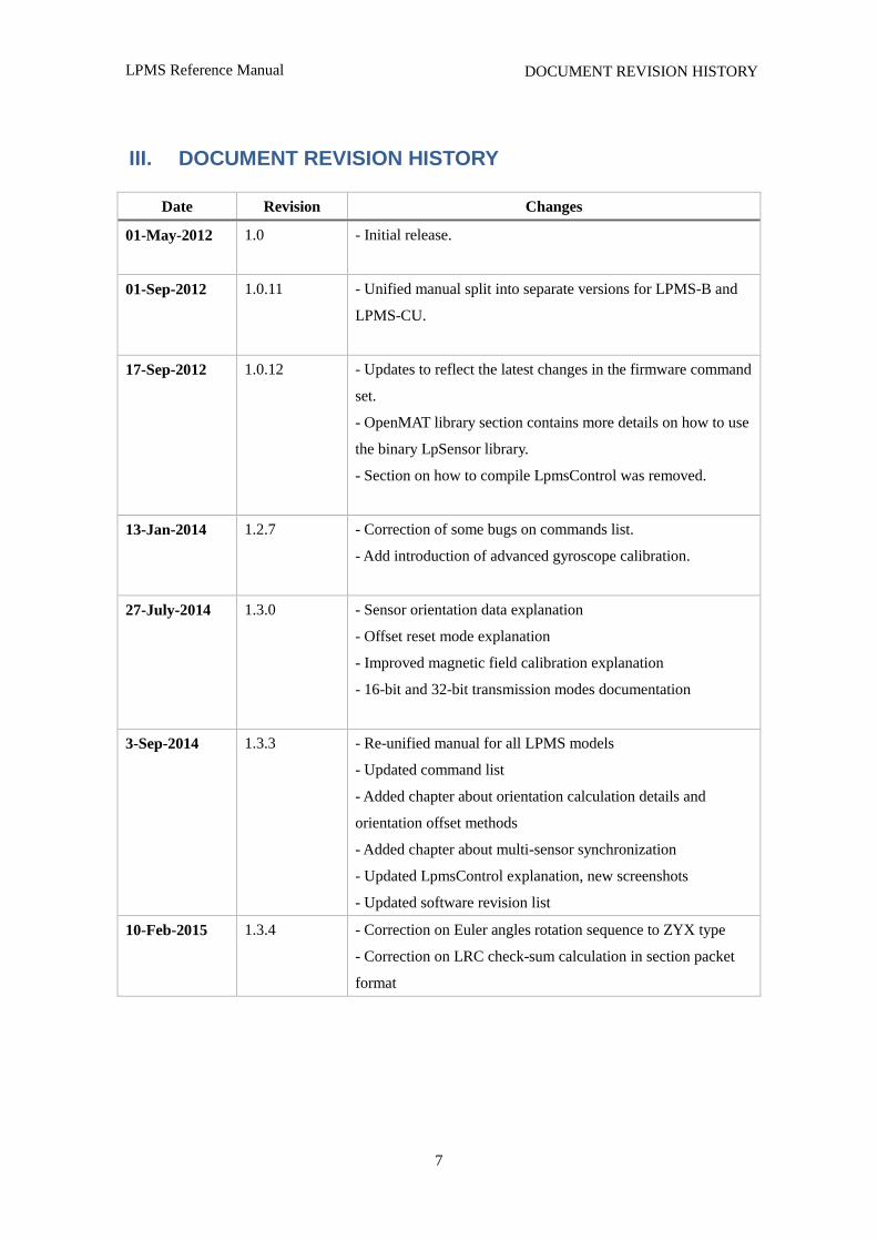
III. DOCUMENT REVISION HISTORY
Date Revision Changes
01-May-2012 1.0 - Initial release.
01-Sep-2012 1.0.11 - Unified manual split into separate versions for LPMS-B and
LPMS-CU.
17-Sep-2012 1.0.12 - Updates to reflect the latest changes in the firmware command
set.
- OpenMAT library section contains more details on how to use
the binary LpSensor library.
- Section on how to compile LpmsControl was removed.
13-Jan-2014 1.2.7 - Correction of some bugs on commands list.
- Add introduction of advanced gyroscope calibration.
27-July-2014 1.3.0 - Sensor orientation data explanation
- Offset reset mode explanation
- Improved magnetic field calibration explanation
- 16-bit and 32-bit transmission modes documentation
3-Sep-2014 1.3.3 - Re-unified manual for all LPMS models
- Updated command list
- Added chapter about orientation calculation details and
orientation offset methods
- Added chapter about multi-sensor synchronization
- Updated LpmsControl explanation, new screenshots
- Updated software revision list
10-Feb-2015 1.3.4 - Correction on Euler angles rotation sequence to ZYX type
- Correction on LRC check-sum calculation in section packet
format
LPMS Reference Manual
8
INTRODUCTION
IV. INTRODUCTION
Measurement Output
The LP-RESEARCH Motion Sensor (LPMS) is a miniature, multi-purpose inertial measurement
unit. We designed the unit to be as small as possible so that it can be used in a wide range of
applications, from measuring the human motion to the stabilization of ground vehicles or airplanes.
The unit can measure orientation in 360 degrees about all three global axes. Measurements are taken
digitally and transmitted to a data analysis system in the form of orientation quaternion or Euler
angles. Whereas Euler angles are one way of describing the orientation of an object, a quaternion
allows orientation measurement without encountering the so-called Gimbal‟s lock. This is achieved
by using a four-element vector to express orientation around all axes without being limited by
singularities. A more in-depth explanation of the quaternion output of the LPMS will follow further
on in this manual. Optionally an LPMS can be equipped with a barometric pressure sensor to extend
the application range of the sensor and to be used e.g. in connection with a GPS unit for global
position measurements.
Technical Background
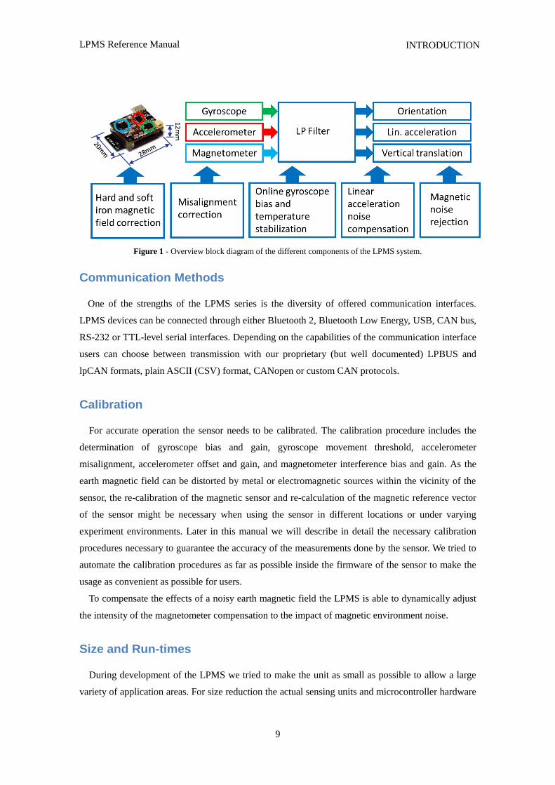
To measure the orientation of an object, the sensor internally uses three different sensing
units(four if the optional pressure sensor is used). These units are micro-electro-mechanical system
(MEMS) sensors that integrate complex mechanical and electronic capabilities on a miniaturized
device. The units used in the LPMS for orientation determination are a 3-axis gyroscope (detecting
angular velocity), a 3-axis accelerometer (detecting the directing of the earth‟s gravity field) and a
3-axis magnetometer to measure the direction of the earth magnetic field. In principle orientation
data about all three room axes can be determined by integrating the angular velocity data from the
gyroscope. However through the integration step the error from the gyroscope measurements,
although it might be very small, has an exponential influence on the calculation causing the resulting
angle values to drift. Therefore we correct the orientation data from the gyroscope with information
from the accelerometer (roll and pitch) and magnetometer (yaw) to calculate orientation information
of high accuracy and stability while guaranteeing fast sampling rates. We combine the orientation
information from the three sensing units using a complementary filter in conjunction with an
extended Kalman filter (EKF), resulting in the so-called LP-Filter. The Kalman filter allows us to
reduce the measurement error especially in case of regular movements (e.g. human gait analysis,
vehicle vibration analysis etc.). The internal sampling and filtering rate of the sensor is 400Hz. The
data stream frequency is independent from the sampling and processing rate and can be adjusted
depending on the selected communication interface.
LPMS Reference Manual
9
INTRODUCTION
Figure 1 - Overview block diagram of the different components of the LPMS system.
Communication Methods
One of the strengths of the LPMS series is the diversity of offered communication interfaces.
LPMS devices can be connected through either Bluetooth 2, Bluetooth Low Energy, USB, CAN bus,
RS-232 or TTL-level serial interfaces. Depending on the capabilities of the communication interface
users can choose between transmission with our proprietary (but well documented) LPBUS and
lpCAN formats, plain ASCII (CSV) format, CANopen or custom CAN protocols.
Calibration
For accurate operation the sensor needs to be calibrated. The calibration procedure includes the
determination of gyroscope bias and gain, gyroscope movement threshold, accelerometer
misalignment, accelerometer offset and gain, and magnetometer interference bias and gain. As the
earth magnetic field can be distorted by metal or electromagnetic sources within the vicinity of the
sensor, the re-calibration of the magnetic sensor and re-calculation of the magnetic reference vector
of the sensor might be necessary when using the sensor in different locations or under varying
experiment environments. Later in this manual we will describe in detail the necessary calibration
procedures necessary to guarantee the accuracy of the measurements done by the sensor. We tried to
automate the calibration procedures as far as possible inside the firmware of the sensor to make the
usage as convenient as possible for users.
To compensate the effects of a noisy earth magnetic field the LPMS is able to dynamically adjust
the intensity of the magnetometer compensation to the impact of magnetic environment noise.
Size and Run-times
During development of the LPMS we tried to make the unit as small as possible to allow a large
variety of application areas. For size reduction the actual sensing units and microcontroller hardware
LPMS Reference Manual
10
INTRODUCTION
are integrated into one main-board with a 6-layer PCB design. The communication hardware
interface is implemented on an extension-board, which is stacked above the main-board. Each LPMS
consists of these two boards as a whole unit (except the module of LPMS-CURS which has only one
board). The main-board contains the actual sensor devices and manages the sensor data acquisition.
The extension-board contains the communication hardware to transmit data to a host system
Application Areas
The LPMS is suitable for a wide range of applications. One of the applications focuses for a small
scale motion sensor is the measurement of human movement for injury rehabilitation, gait cycle
analysis, surgical skill training etc. The sensor can also be effectively used in the field of virtual
reality, navigation, robotics, or for measuring vehicle dynamics. If more than one sensor is used for a
sensor network the motion of complex objects as necessary in cinematic motion capturing or
animation movie production is possible.
LPMS Reference Manual
11
DEVICE SPECIFICATIONS
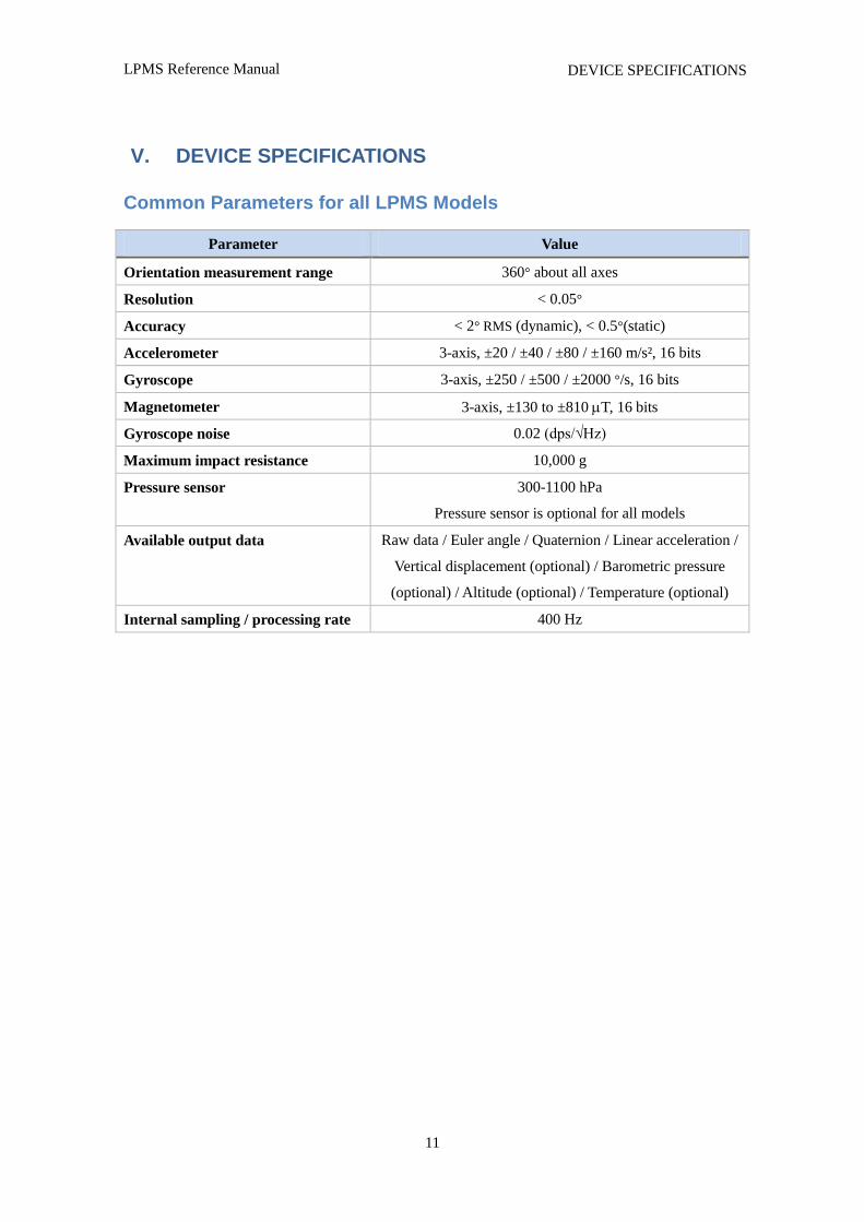
V. DEVICE SPECIFICATIONS
Common Parameters for all LPMS Models
Parameter Value
Orientation measurement range 360° about all axes
Resolution < 0.05°
Accuracy < 2° RMS (dynamic), < 0.5°(static)
Accelerometer 3-axis, ±20 / ±40 / ±80 / ±160 m/s², 16 bits
Gyroscope 3-axis, ±250 / ±500 / ±2000 °/s, 16 bits
Magnetometer 3-axis, ±130 to ±810 T, 16 bits
Gyroscope noise 0.02 (dps/√Hz)
Maximum impact resistance 10,000 g
Pressure sensor 300-1100 hPa
Pressure sensor is optional for all models
Available output data Raw data / Euler angle / Quaternion / Linear acceleration /
Vertical displacement (optional) / Barometric pressure
(optional) / Altitude (optional) / Temperature (optional)
Internal sampling / processing rate 400 Hz
LPMS Reference Manual
12
DEVICE SPECIFICATIONS
Device Specific Parameters and Connectors
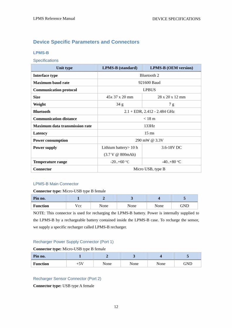
LPMS-B
Specifications
Unit type LPMS-B (standard) LPMS-B (OEM version)
Interface type Bluetooth 2
Maximum baud rate 921600 Baud
Communication protocol LPBUS
Size 45x 37 x 20 mm 28 x 20 x 12 mm
Weight 34 g 7 g
Bluetooth 2.1 + EDR, 2.412 - 2.484 GHz
Communication distance < 18 m
Maximum data transmission rate 133Hz
Latency 15 ms
Power consumption 290 mW @ 3.3V
Power supply Lithium battery> 10 h
(3.7 V @ 800mAh)
3.6-18V DC
Temperature range -20..+60 °C -40..+80 °C
Connector Micro USB, type B
LPMS-B Main Connector
Connector type: Micro-USB type B female
Pin no. 1 2 3 4 5
Function Vcc None None None GND
NOTE: This connector is used for recharging the LPMS-B battery. Power is internally supplied to
the LPMS-B by a rechargeable battery contained inside the LPMS-B case. To recharge the sensor,
we supply a specific recharger called LPMS-B recharger.
Recharger Power Supply Connector (Port 1)
Connector type: Micro-USB type B female
Pin no. 1 2 3 4 5
Function +5V None None None GND
Recharger Sensor Connector (Port 2)
Connector type: USB type A female
LPMS Reference Manual
13
DEVICE SPECIFICATIONS
Pin no. 1 2 3 4 5
Function Vcc None None None GND
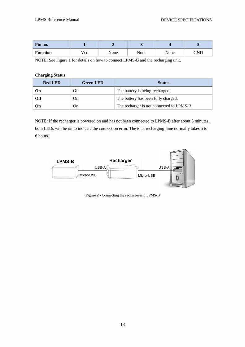
NOTE: See Figure 1 for details on how to connect LPMS-B and the recharging unit.
Charging Status
Red LED Green LED Status
On Off The battery is being recharged.
Off On The battery has been fully charged.
On On The recharger is not connected to LPMS-B.
NOTE: If the recharger is powered on and has not been connected to LPMS-B after about 5 minutes,
both LEDs will be on to indicate the connection error. The total recharging time normally takes 5 to
6 hours.
Figure 2 - Connecting the recharger and LPMS-B
LPMS Reference Manual
14
DEVICE SPECIFICATIONS
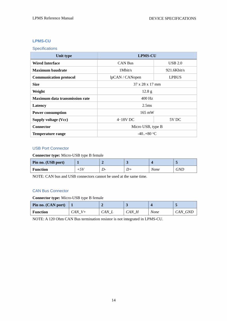
LPMS-CU
Specifications
Unit type LPMS-CU
Wired Interface CAN Bus USB 2.0
Maximum baudrate 1Mbit/s 921.6Kbit/s
Communication protocol lpCAN / CANopen LPBUS
Size 37 x 28 x 17 mm
Weight 12.8 g
Maximum data transmission rate 400 Hz
Latency 2.5ms
Power consumption 165 mW
Supply voltage (Vcc) 4-18V DC 5V DC
Connector Micro USB, type B
Temperature range -40..+80 °C
USB Port Connector
Connector type: Micro-USB type B female
Pin no. (USB port) 1 2 3 4 5
Function +5V D- D+ None GND
NOTE: CAN bus and USB connectors cannot be used at the same time.
CAN Bus Connector
Connector type: Micro-USB type B female
Pin no. (CAN port) 1 2 3 4 5
Function CAN_V+ CAN_L CAN_H None CAN_GND
NOTE: A 120 Ohm CAN Bus termination resistor is not integrated in LPMS-CU.
LPMS Reference Manual
15
DEVICE SPECIFICATIONS
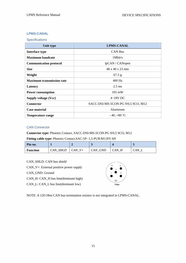
LPMS-CANAL
Specifications
Unit type LPMS-CANAL
Interface type CAN Bus
Maximum baudrate 1Mbit/s
Communication protocol lpCAN / CANopen
Size 48 x 40 x 23 mm
Weight 67.5 g
Maximum transmission rate 400 Hz
Latency 2.5 ms
Power consumption 165 mW
Supply voltage (Vcc) 4-18V DC
Connector SACC-DSI-MS-5CON-PG 9/0,5 SCO, M12
Case material Aluminum
Temperature range - 40..+80 °C
CAN Connector
Connector type: Phoenix Contact, SACC-DSI-MS-5CON-PG 9/0,5 SCO, M12
Fitting cable type: Phoenix Contact,SAC-5P- 1,5-PUR/M12FS SH
Pin no. 1 2 3 4 5
Function CAN_SHLD CAN_V+ CAN_GND CAN_H CAN_L
CAN_SHLD: CAN bus shield
CAN_V+: External positive power supply
CAN_GND: Ground
CAN_H: CAN_H bus line(dominant high)
CAN_L: CAN_L bus line(dominant low)
NOTE: A 120 Ohm CAN bus termination resistor is not integrated in LPMS-CANAL.
LPMS Reference Manual
16
DEVICE SPECIFICATIONS
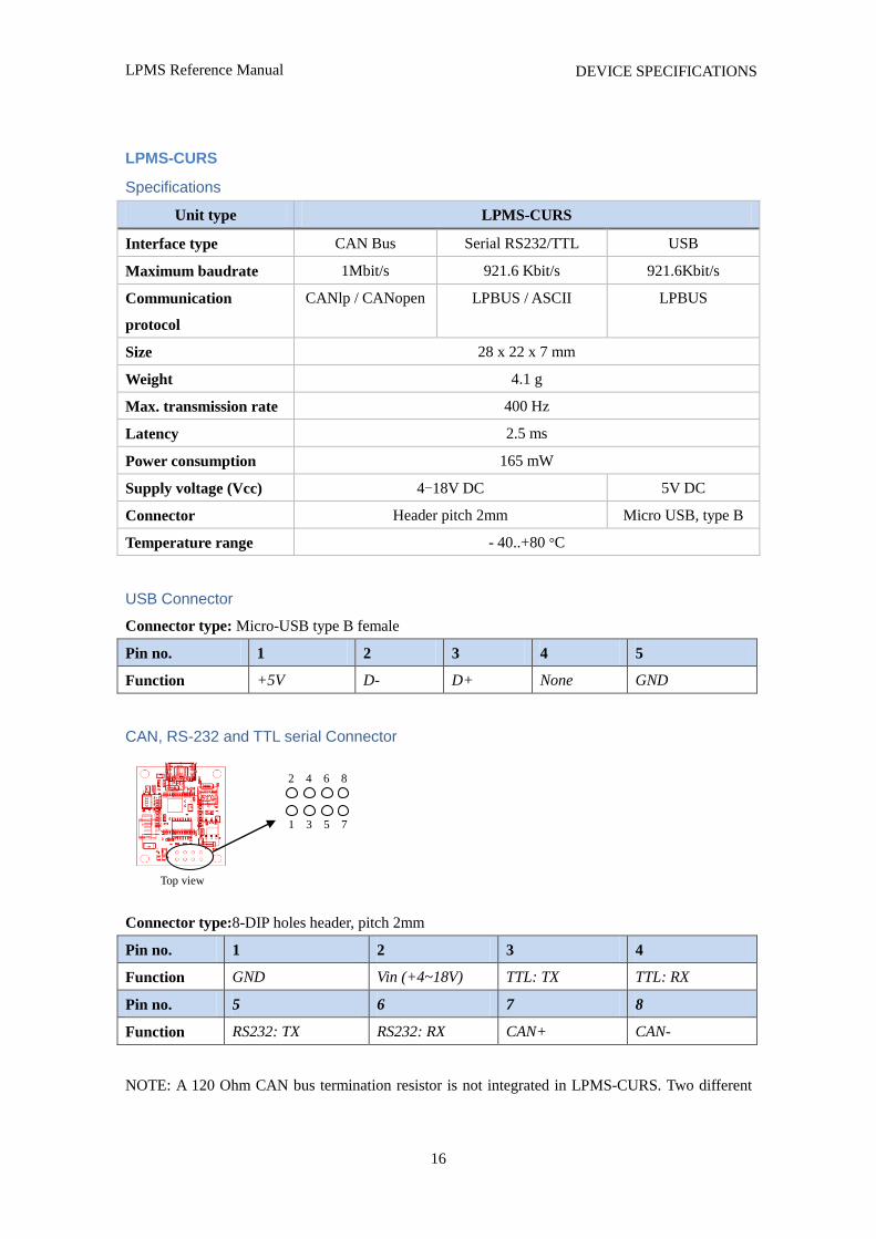
LPMS-CURS
Specifications
Unit type LPMS-CURS
Interface type CAN Bus Serial RS232/TTL USB
Maximum baudrate 1Mbit/s 921.6 Kbit/s 921.6Kbit/s
Communication
protocol
CANlp / CANopen LPBUS / ASCII LPBUS
Size 28 x 22 x 7 mm
Weight 4.1 g
Max. transmission rate 400 Hz
Latency 2.5 ms
Power consumption 165 mW
Supply voltage (Vcc) 4-18V DC 5V DC
Connector Header pitch 2mm Micro USB, type B
Temperature range - 40..+80 °C
USB Connector
Connector type: Micro-USB type B female
Pin no. 1 2 3 4 5
Function +5V D- D+ None GND
CAN, RS-232 and TTL serial Connector
Connector type:8-DIP holes header, pitch 2mm
Pin no. 1 2 3 4
Function GND Vin (+4~18V) TTL: TX TTL: RX
Pin no. 5 6 7 8
Function RS232: TX RS232: RX CAN+ CAN-
NOTE: A 120 Ohm CAN bus termination resistor is not integrated in LPMS-CURS. Two different
1 3 5 7
2 4 6 8
Top view

LPMS Reference Manual
17
DEVICE SPECIFICATIONS
interface connectors cannot be used at the same time.
NOTE: LPMS-CURS is available in different firmware configurations, supporting:
1. CAN bus and USB. Data is streamed via CAN bus at power-on.
2. RS-232 and USB. Data is streamed via RS-232 at power-on.
3. TTL serial and USB. Data is streamed via TTL serial at power-on.
The USB port for all three modules above is for communicating with a PC-based host system.
LPMS Reference Manual
18
DEVICE SPECIFICATIONS
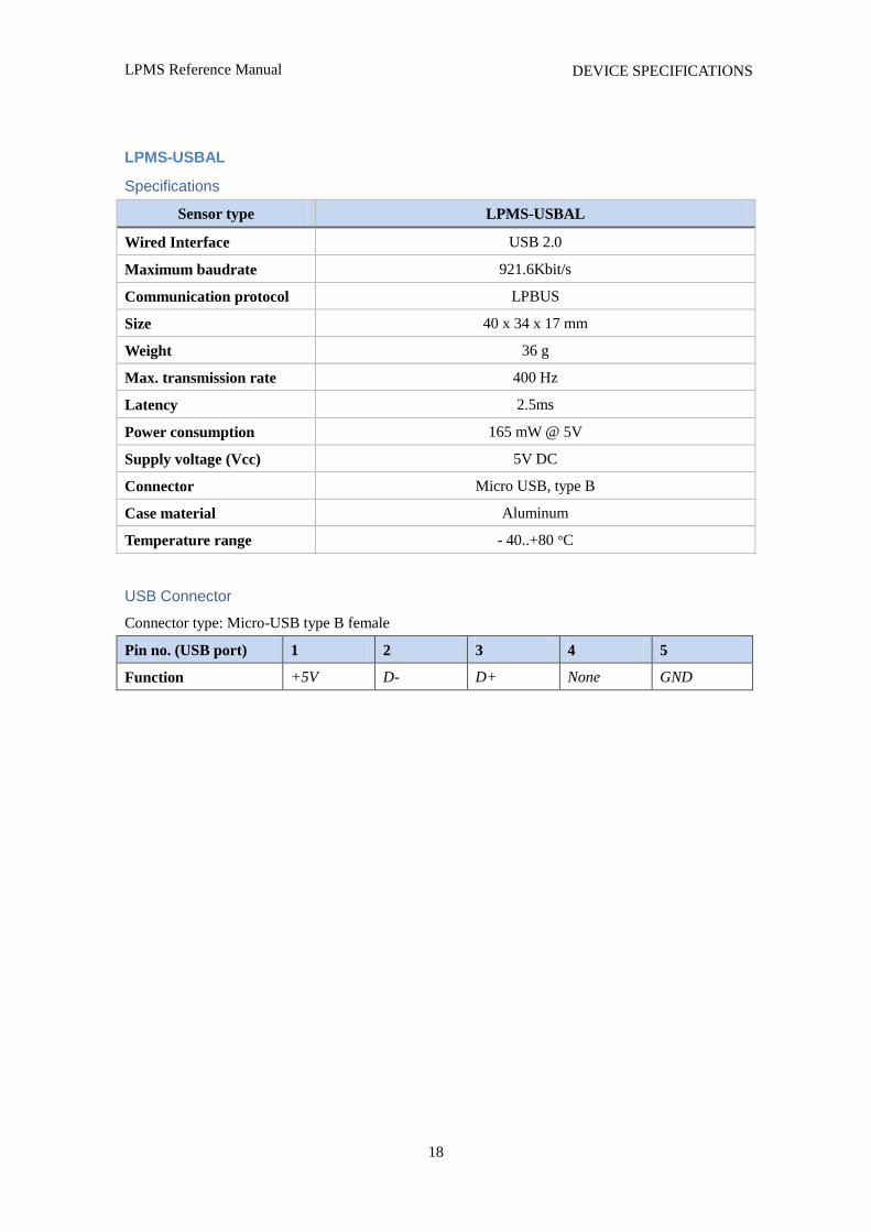
LPMS-USBAL
Specifications
Sensor type LPMS-USBAL
Wired Interface USB 2.0
Maximum baudrate 921.6Kbit/s
Communication protocol LPBUS
Size 40 x 34 x 17 mm
Weight 36 g
Max. transmission rate 400 Hz
Latency 2.5ms
Power consumption 165 mW @ 5V
Supply voltage (Vcc) 5V DC
Connector Micro USB, type B
Case material Aluminum
Temperature range - 40..+80 °C
USB Connector
Connector type: Micro-USB type B female
Pin no. (USB port) 1 2 3 4 5
Function +5V D- D+ None GND
LPMS Reference Manual
19
OPERATION
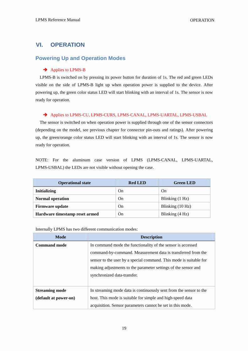
VI. OPERATION
Powering Up and Operation Modes
Applies to LPMS-B
LPMS-B is switched on by pressing its power button for duration of 1s. The red and green LEDs
visible on the side of LPMS-B light up when operation power is supplied to the device. After
powering up, the green color status LED will start blinking with an interval of 1s. The sensor is now
ready for operation.
Applies to LPMS-CU, LPMS-CURS, LPMS-CANAL, LPMS-UARTAL, LPMS-USBAL
The sensor is switched on when operation power is supplied through one of the sensor connectors
(depending on the model, see previous chapter for connector pin-outs and ratings). After powering
up, the green/orange color status LED will start blinking with an interval of 1s. The sensor is now
ready for operation.
NOTE: For the aluminum case version of LPMS (LPMS-CANAL, LPMS-UARTAL,
LPMS-USBAL) the LEDs are not visible without opening the case.
Operational state Red LED Green LED
Initializing On On
Normal operation On Blinking (1 Hz)
Firmware update On Blinking (10 Hz)
Hardware timestamp reset armed On Blinking (4 Hz)
Internally LPMS has two different communication modes:
Mode Description
Command mode In command mode the functionality of the sensor is accessed
command-by-command. Measurement data is transferred from the
sensor to the user by a special command. This mode is suitable for
making adjustments to the parameter settings of the sensor and
synchronized data-transfer.
Streaming mode
(default at power-on)
In streaming mode data is continuously sent from the sensor to the
host. This mode is suitable for simple and high-speed data
acquisition. Sensor parameters cannot be set in this mode.
LPMS Reference Manual
20
OPERATION
NOTE: The sensor is set to streaming mode by default after powering on. Command mode may
be set via the corresponding LPBUS command. The current operation mode can be saved into sensor
flash memory. We will specify the available commands in detail later on in this manual.
Applies to LPMS-CU, LPMS-CURS CAN version, LPMS-CANAL
Data is initially streamed via CAN bus. Data communication is switched to USB once the first
LPBUS byte has been received through the USB port.
Applies LPMS-UARTAL, LPMS-CURS RS-232 and TTL versions
Data is initially streamed via serial port. Data communication is switched to USB once the first
LPBUS byte has been received through the USB port.
LPMS Reference Manual
21
OPERATION
Host Device Communication
Bluetooth 2
Applies to LPMS-B
To connect to the sensor, a Bluetooth connection request must be sent to the Bluetooth MAC
address of LPMS-B. This MAC address is displayed as sensor device ID in the LpmsControl
application.
Users should connect to the Bluetooth module of LPMS-B using a standard class 2 Bluetooth host
interface that supports SPP (serial protocol profile). A key-code for pairing is not normally required.
Should you be asked for a key-code anyway, enter “1234”. Establishing a connection with the sensor
usually takes around 2 to 5 seconds. The Bluetooth device name of the sensor for device discovery is
LPMS-B. The baudrate of the Bluetooth connection is 921600bit/s.
NOTE: Bluetooth communication always uses the LPBUS binary format for input / output.
USB
Applies to LPMS-CU, LPMS-CURS, LPMS-USBAL
The USB interface of the LPMS-USBAL, LPMS-CU or LPMS-CURS uses a serial-to-USB
interface IC by the company FTDI. Drivers for this IC for all major operating systems can be
downloaded from their website: http://www.ftdichip.com/FTDrivers.htm.
There are two options for communicating with the FTDI chip:
1. By downloading a virtual com port driver (VCP): This driver allows you to see the LPMS as
COM port in your operating system. All communication is done using standard COM port
access procedures. The default connection baudrate is 912.6Kbit/s, 8N1, with hardware flow
control.
2. By accessing the FTDI chip directly using a DLL library: FTDI offers a convenient library that
allows users to communicate with their USB interface ICs.
NOTE: USB communication always uses the LPBUS binary format for input / output.
CAN Bus
Applies to LPMS-CU, LPMS-CANAL, LPMS-CURS
Users should be able to communicate with LPMS-CU, LPMS-CANAL or LPMS-CURS using
any standard CAN interface. The CAN message uses standard 11 bits identifier and 8 bytes of data.
The default connection baud rate is 125Kbit/s.
LPMS Reference Manual
22
OPERATION
CAN bus communication can be switched to one of the following formats:
1. CANopen (default) messages, output only
2. Sequential (custom) CAN messages, output only
3. LPBUS binary format (lpCAN)
NOTE: Format settings can be changed through LpmsControl application or direct LPBUS
communication commands.
RS-232, TTL-level serial
Applies to LPMS-CURS, LPMS-UARTAL
The UART interface for both, RS232 and TTL-level serial uses a baud rate default setting of
115200 bit/s, 8N1, no hardware flow control.
RS-232 and TTL-level serial communication can be switched to one of the following formats:
1. LP-BUS binary (default)
2. ASCII plain text
NOTE: Format settings can be changed through the LpmsControl application or direct LPBUS
communication commands.
LPMS Reference Manual
23
OPERATION
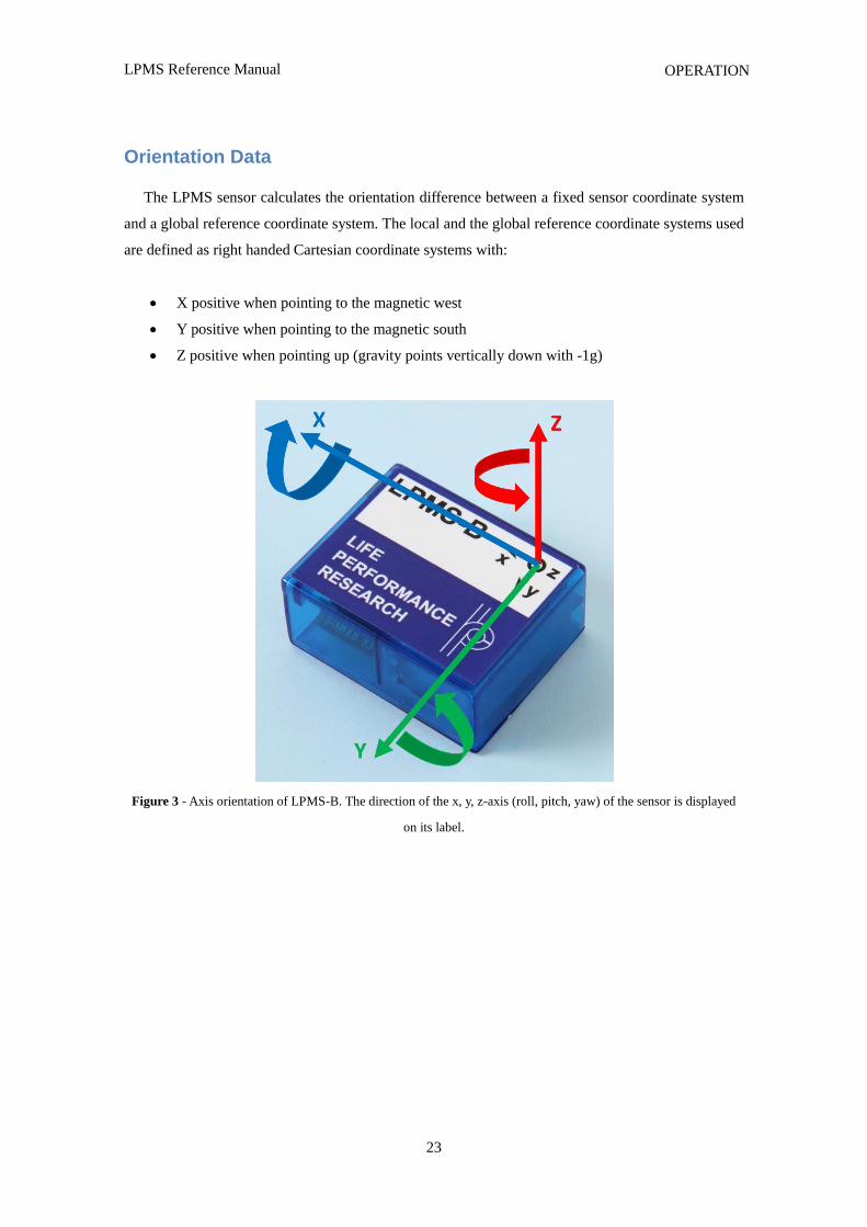
Orientation Data
The LPMS sensor calculates the orientation difference between a fixed sensor coordinate system
and a global reference coordinate system. The local and the global reference coordinate systems used
are defined as right handed Cartesian coordinate systems with:
X positive when pointing to the magnetic west
Y positive when pointing to the magnetic south
Z positive when pointing up (gravity points vertically down with -1g)
Figure 3 - Axis orientation of LPMS-B. The direction of the x, y, z-axis (roll, pitch, yaw) of the sensor is displayed
on its label.
LPMS Reference Manual
24
OPERATION
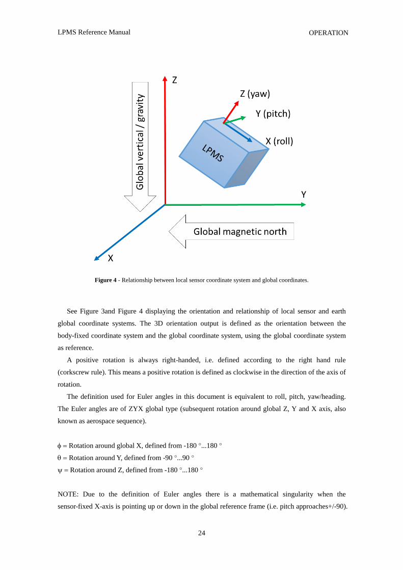
Figure 4 - Relationship between local sensor coordinate system and global coordinates.
See Figure 3and Figure 4 displaying the orientation and relationship of local sensor and earth
global coordinate systems. The 3D orientation output is defined as the orientation between the
body-fixed coordinate system and the global coordinate system, using the global coordinate system
as reference.
A positive rotation is always right-handed, i.e. defined according to the right hand rule
(corkscrew rule). This means a positive rotation is defined as clockwise in the direction of the axis of
rotation.
The definition used for Euler angles in this document is equivalent to roll, pitch, yaw/heading.
The Euler angles are of ZYX global type (subsequent rotation around global Z, Y and X axis, also
known as aerospace sequence).
Rotation around global X, defined from -180 °...180 °
Rotation around Y, defined from -90 °...90 °
Rotation around Z, defined from -180 °...180 °
NOTE: Due to the definition of Euler angles there is a mathematical singularity when the
sensor-fixed X-axis is pointing up or down in the global reference frame (i.e. pitch approaches+/-90).
LPMS Reference Manual
25
OPERATION
This singularity is not present in quaternion output.
Sensor Orientation Alignment Modes
Heading reset
Often it is important that the global Z-axis remains along the vertical (defined by local gravity
vector), but the global X-axis has to be in a particular direction. In this case a heading reset may be
used. When performing a heading reset, the new global reference frame is chosen such that the
global X-axis points in the direction of the sensor while keeping the global Z-axis vertical (along
gravity, pointing upwards). In other words: The global Z-axis point upwards along gravity, where the
X and Y axis orthogonally form a perpendicular plane.
NOTE: After a heading reset, the yaw may not be exactly zero, this occurs especially when the
X-axis is close to the vertical. This is caused by the definition of the yaw when using Euler angles,
which becomes unstable when the pitch approaches +/-90 deg.
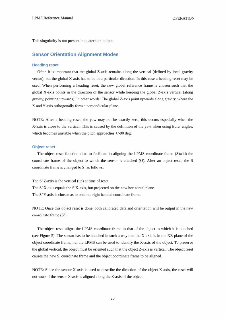
Object reset
The object reset function aims to facilitate in aligning the LPMS coordinate frame (S)with the
coordinate frame of the object to which the sensor is attached (O). After an object reset, the S
coordinate frame is changed to S‟ as follows:
The S‟ Z-axis is the vertical (up) at time of reset
The S‟ X-axis equals the S X-axis, but projected on the new horizontal plane.
The S‟ Y-axis is chosen as to obtain a right handed coordinate frame.
NOTE: Once this object reset is done, both calibrated data and orientation will be output in the new
coordinate frame (S‟).
The object reset aligns the LPMS coordinate frame to that of the object to which it is attached
(see Figure 5). The sensor has to be attached in such a way that the X-axis is in the XZ-plane of the
object coordinate frame, i.e. the LPMS can be used to identify the X-axis of the object. To preserve
the global vertical, the object must be oriented such that the object Z-axis is vertical. The object reset
causes the new S‟ coordinate frame and the object coordinate frame to be aligned.
NOTE: Since the sensor X-axis is used to describe the direction of the object X-axis, the reset will
not work if the sensor X-axis is aligned along the Z-axis of the object.
LPMS Reference Manual
26
OPERATION
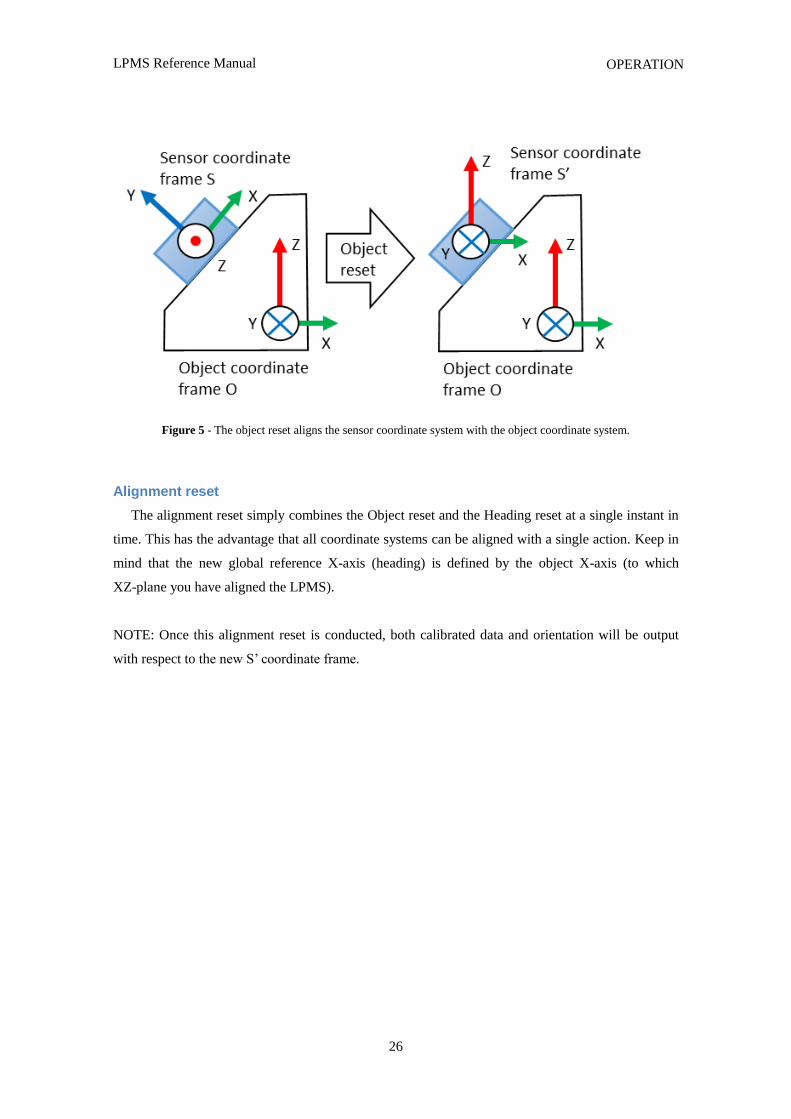
Figure 5 - The object reset aligns the sensor coordinate system with the object coordinate system.
Alignment reset
The alignment reset simply combines the Object reset and the Heading reset at a single instant in
time. This has the advantage that all coordinate systems can be aligned with a single action. Keep in
mind that the new global reference X-axis (heading) is defined by the object X-axis (to which
XZ-plane you have aligned the LPMS).
NOTE: Once this alignment reset is conducted, both calibrated data and orientation will be output
with respect to the new S‟ coordinate frame.
LPMS Reference Manual
27
OPERATION
Data Acquisition
Raw Sensor Data
The LPMS contains three MEMS sensors: A gyroscope, an accelerometer and a magnetometer.
The raw data from all three of these sensors can be accessed by the host system based on the LPBUS
protocol. The raw sensor data can be used to check if the current acquisition range of the sensors is
sufficient and if the different sensors generate correct output. Users can also implement their own
sensor fusion algorithms using the raw sensor data values. Sensor range and data sampling speed can
be set by sending commands to the firmware.
The LPMS is delivered in a factory-calibrated state, but it might be necessary to recalibrate the
sensors if the measurement environment changes (different ambient electromagnetic field, strong
temperature change). Please refer to the following sections for a detailed introduction of sensor
calibration methods.
1. Gyroscope raw data: Data from sensor is calibrated (bias, scaling and misalignment applied)
2. Accelerometer raw data: Data from sensor is calibrated (bias, scaling and misalignment applied)
3. Magnetometer raw data: Data from sensor is scaled, but not hard / soft iron calibrated (scaling
and misalignment applied)
Orientation Data
The LPMS has two orientation output formats: quaternion and Euler angle. As the Euler angle
representation of orientation is subject to the Gimbal lock, we strongly recommend users to rely on
quaternion representation for orientation calculation.
LPMS Reference Manual
28
OPERATION
Filter Settings
Data from the three MEMS sensors is combined using an extended complementary Kalman filter
(LP-Filter) to calculate the orientation data, like quaternion and Euler angle. To make the filter
operate correctly, its parameters need to be set in an appropriate way.
Filter Modes
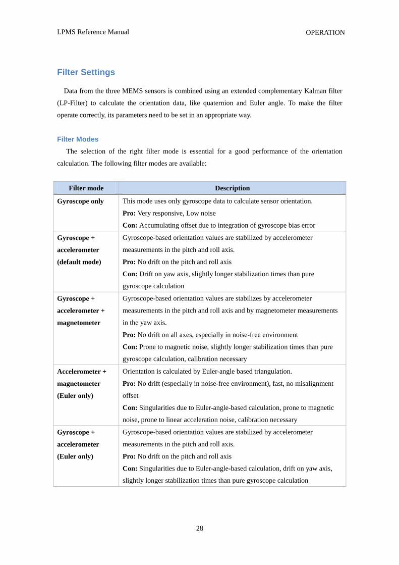
The selection of the right filter mode is essential for a good performance of the orientation
calculation. The following filter modes are available:
Filter mode Description
Gyroscope only This mode uses only gyroscope data to calculate sensor orientation.
Pro: Very responsive, Low noise
Con: Accumulating offset due to integration of gyroscope bias error
Gyroscope +
accelerometer
(default mode)
Gyroscope-based orientation values are stabilized by accelerometer
measurements in the pitch and roll axis.
Pro: No drift on the pitch and roll axis
Con: Drift on yaw axis, slightly longer stabilization times than pure
gyroscope calculation
Gyroscope +
accelerometer +
magnetometer
Gyroscope-based orientation values are stabilizes by accelerometer
measurements in the pitch and roll axis and by magnetometer measurements
in the yaw axis.
Pro: No drift on all axes, especially in noise-free environment
Con: Prone to magnetic noise, slightly longer stabilization times than pure
gyroscope calculation, calibration necessary
Accelerometer +
magnetometer
(Euler only)
Orientation is calculated by Euler-angle based triangulation.
Pro: No drift (especially in noise-free environment), fast, no misalignment
offset
Con: Singularities due to Euler-angle-based calculation, prone to magnetic
noise, prone to linear acceleration noise, calibration necessary
Gyroscope +
accelerometer
(Euler only)
Gyroscope-based orientation values are stabilized by accelerometer
measurements in the pitch and roll axis.
Pro: No drift on the pitch and roll axis
Con: Singularities due to Euler-angle-based calculation, drift on yaw axis,
slightly longer stabilization times than pure gyroscope calculation
LPMS Reference Manual
29
OPERATION
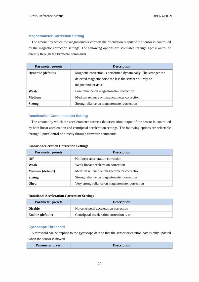
Magnetometer Correction Setting
The amount by which the magnetometer corrects the orientation output of the sensor is controlled
by the magnetic correction settings. The following options are selectable through LpmsControl or
directly through the firmware commands.
Parameter presets Description
Dynamic (default) Magnetic correction is performed dynamically. The stronger the
detected magnetic noise the less the sensor will rely on
magnetometer data.
Weak Low reliance on magnetometer correction
Medium Medium reliance on magnetometer correction
Strong Strong reliance on magnetometer correction
Acceleration Compensation Setting
The amount by which the accelerometer corrects the orientation output of the sensor is controlled
by both linear acceleration and centripetal acceleration settings. The following options are selectable
through LpmsControl or directly through firmware commands.
Linear Acceleration Correction Settings
Parameter presets Description
Off No linear acceleration correction
Weak Weak linear acceleration correction
Medium (default) Medium reliance on magnetometer correction
Strong Strong reliance on magnetometer correction
Ultra Very strong reliance on magnetometer correction
Rotational Acceleration Correction Settings
Parameter presets Description
Disable No centripetal acceleration correction
Enable (default) Centripetal acceleration correction is on
Gyroscope Threshold
A threshold can be applied to the gyroscope data so that the sensor orientation data is only updated
when the sensor is moved.
Parameter preset Description
LPMS Reference Manual
30
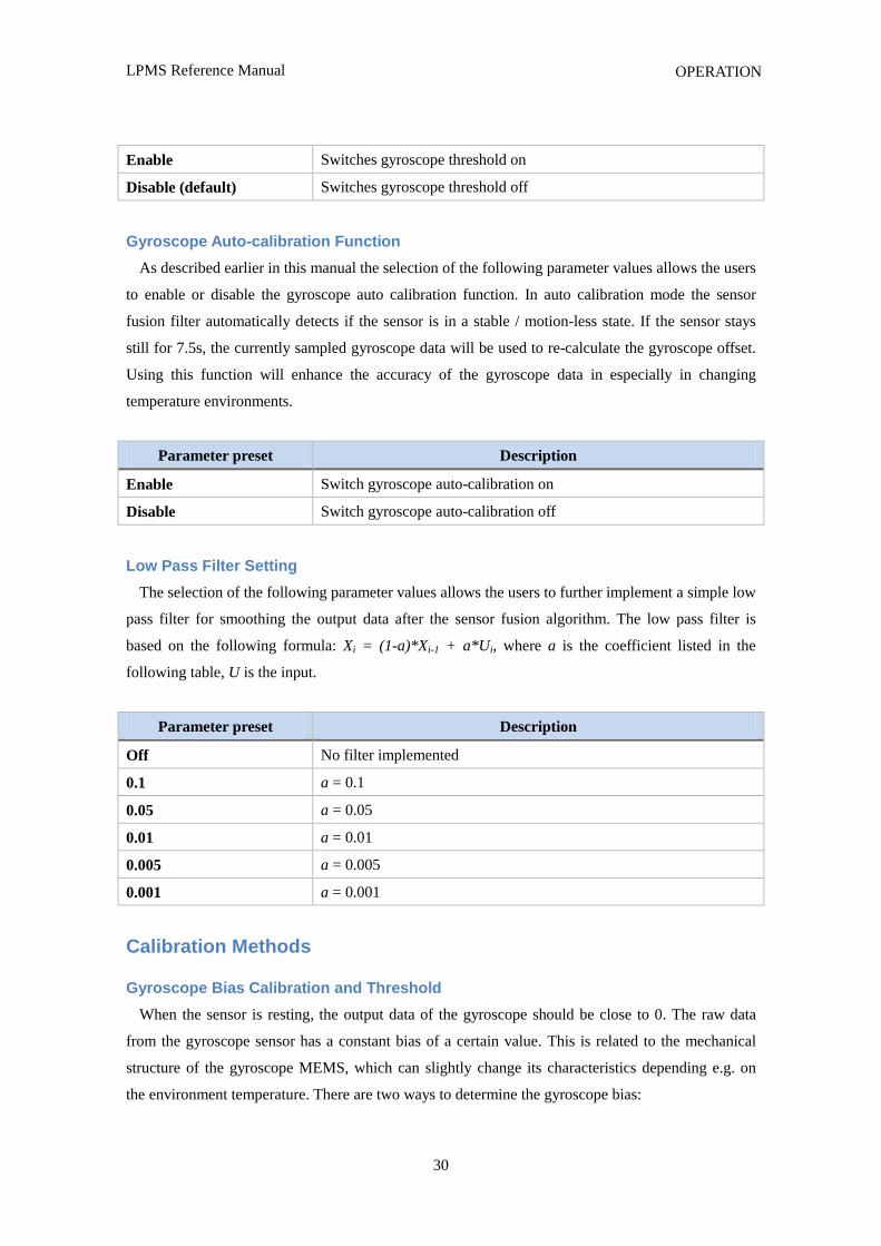
OPERATION
Enable Switches gyroscope threshold on
Disable (default) Switches gyroscope threshold off
Gyroscope Auto-calibration Function
As described earlier in this manual the selection of the following parameter values allows the users
to enable or disable the gyroscope auto calibration function. In auto calibration mode the sensor
fusion filter automatically detects if the sensor is in a stable / motion-less state. If the sensor stays
still for 7.5s, the currently sampled gyroscope data will be used to re-calculate the gyroscope offset.
Using this function will enhance the accuracy of the gyroscope data in especially in changing
temperature environments.
Parameter preset Description
Enable Switch gyroscope auto-calibration on
Disable Switch gyroscope auto-calibration off
Low Pass Filter Setting
The selection of the following parameter values allows the users to further implement a simple low
pass filter for smoothing the output data after the sensor fusion algorithm. The low pass filter is
based on the following formula: Xi = (1-a)*Xi-1 + a*Ui, where a is the coefficient listed in the
following table, U is the input.
Parameter preset Description
Off No filter implemented
0.1 a = 0.1
0.05 a = 0.05
0.01 a = 0.01
0.005 a = 0.005
0.001 a = 0.001
Calibration Methods
Gyroscope Bias Calibration and Threshold
When the sensor is resting, the output data of the gyroscope should be close to 0. The raw data
from the gyroscope sensor has a constant bias of a certain value. This is related to the mechanical
structure of the gyroscope MEMS, which can slightly change its characteristics depending e.g. on
the environment temperature. There are two ways to determine the gyroscope bias:
LPMS Reference Manual
31
OPERATION
1. Automatic calibration: If the sensor is in a motion-less state for more than 7.5s the gyroscope
bias will be automatically readjusted.
2. Manual calibration: To determine the bias value manually the following calibration procedure
needs to be applied. Alternatively to calibration from the LpmsControl application, the calibration
can also be triggered through direct communication with the sensor.
Step Description
1 Put the sensor in a resting (non-moving) position
2 Trigger the gyroscope calibration procedure either through a firmware command or using
the “Calibrate gyroscope” function in LpmsControl software
3 The gyroscope calibration will take around 30s. After that the gyroscope is calibrated,
normal operation can be resumed
The gyroscope threshold will set up an angular speed limit, below which the LPMS will not
process any motion data. This setting can be used to suppress noise or vibrations that might impact
the sensor measurements. Users should be careful when applying this functionality, though, as
motion information below the threshold will be lost and this might significantly reduce the accuracy
of the overall orientation measurement.
Magnetometer Calibration
During the magnetometer calibration procedure several parameters about the magnetic
environment close to the sensor are to be determined: magnetometer bias / gain on the X, Y and
Z-axis and length / direction of the local geomagnetic field vector. In most environments the earth
magnetic field is influenced by electromagnetic noise sources such as power lines, metal etc. As a
result the magnetic field becomes de-centered and deformed.
LPMS Reference Manual
32
OPERATION
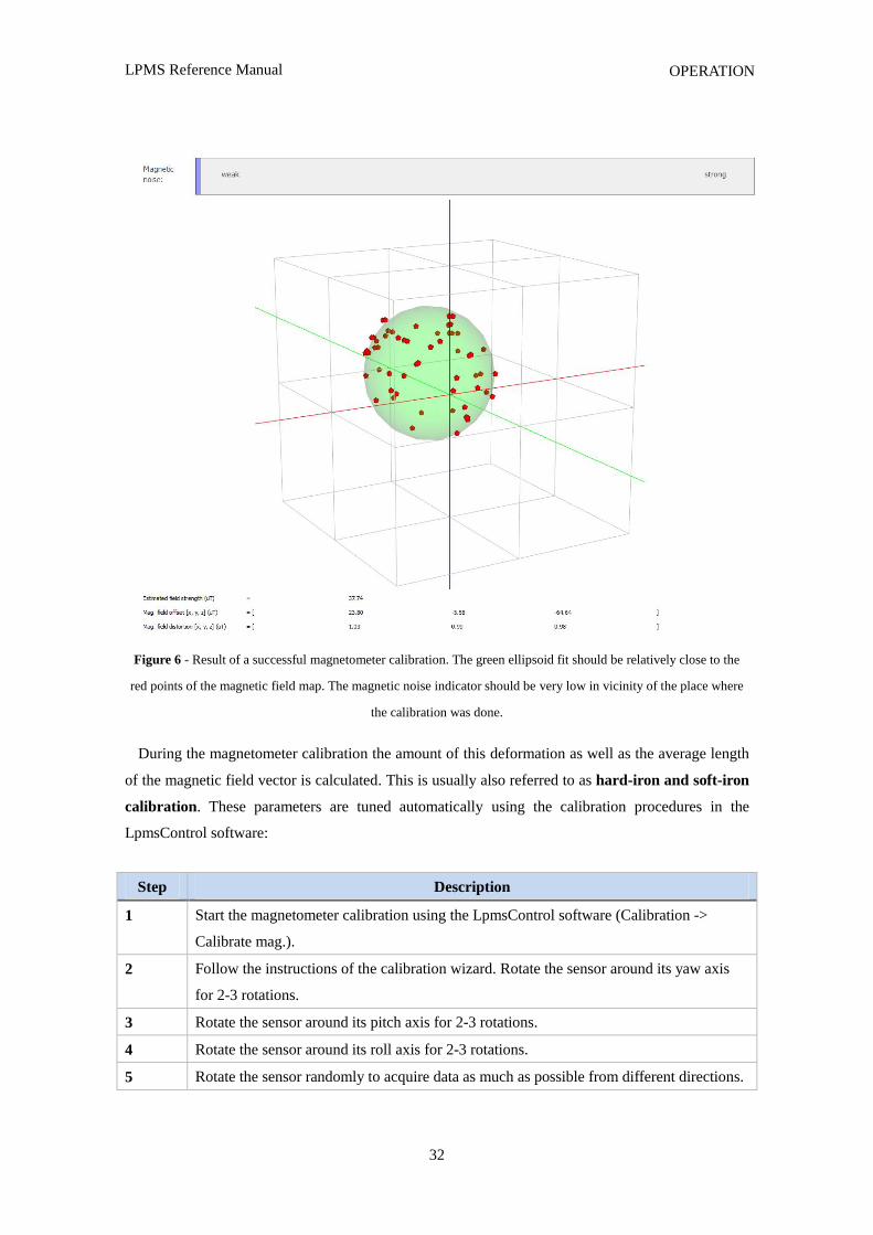
Figure 6 - Result of a successful magnetometer calibration. The green ellipsoid fit should be relatively close to the
red points of the magnetic field map. The magnetic noise indicator should be very low in vicinity of the place where
the calibration was done.
During the magnetometer calibration the amount of this deformation as well as the average length
of the magnetic field vector is calculated. This is usually also referred to as hard-iron and soft-iron
calibration. These parameters are tuned automatically using the calibration procedures in the
LpmsControl software:
Step Description
1 Start the magnetometer calibration using the LpmsControl software (Calibration ->
Calibrate mag.).
2 Follow the instructions of the calibration wizard. Rotate the sensor around its yaw axis
for 2-3 rotations.
3 Rotate the sensor around its pitch axis for 2-3 rotations.
4 Rotate the sensor around its roll axis for 2-3 rotations.
5 Rotate the sensor randomly to acquire data as much as possible from different directions.
LPMS Reference Manual
33
OPERATION
6 The collection of the field map data is finished after 40 seconds. This is followed by
calculation of the geomagnetic field vector (local earth magnetic field inclination). Keep
the sensor close to the calibration location and press the Next button in the calibration
wizard.
7 After 10 seconds the calibration is complete.
There are two methods for calibrating the hard iron offset and soft iron matrix:
1. Ellipsoid fit: Parameters are calculated by creating a map of the environment field and then fitting
an ellipsoid through the point data. The point cloud after rotating the sensor around its axes should
look similar to Figure 6.
2. Min / max fit: Parameters are calculated by measuring the minimum and maximum field values
for each axis during the sensor rotation process. This method can in principle be used for planar
magnetometer calibration. This is important in cases where the magnetometer is fixed to a reference
frame that can‟t be rotated around all axes e.g. a car.
NOTE: The calculations for the magnetometer calibration are currently executed within the
LpSensor library running on the host. They can‟t be triggered directly from communication
commands on the sensor.
Multiple-device Synchronization
Applies to LPMS-B
Because of the unreliable timing of a Bluetooth connection, multiple LPMS-B cannot be accurately
synchronized over-the-air. LPMS-B offers functionality to use one of its digital IO lines to
synchronize with a trigger signal.
To manually reset the timestamp of LPMS-B to 0, please follow the steps below:
1. Arm manual timestamp reset via LpmsControl or LPBUS command 83
(SET_ARM_HARDWARE_TIMESTAMP_RESET). The green status LED of LPMS-B
should now be blinking at 4Hz.
2. Trigger a timestamp reset by connecting pin 2 of the re-charging connector of LPMS-B to
GND. At the moment of the trigger, the sensor timestamp will be reset to 0. The maximum
delay to occur between trigger and timestamp reset is 2.5ms.
Applies to all models
LPMS Reference Manual
34
COMMUNICATION PROTOCOL
The LPMS timestamp will be reset to 0 automatically after 10737418.2375 seconds.
Trade-offs and Limitations
Although we put a lot of effort into the design of the LPMS, there are a few limitations that need
to be taken into account when using the sensor. The accuracy of the sensor is limited by the
electronic noise level of the MEMS sensors. The system runs at an internal measurement and
processing frequency of 400Hz. The parameters of the filter that fuses the data from the gyroscope,
magnetometer and accelerometer need to be adjusted well, in order to achieve measurements with
maximum accuracy. Furthermore, in case the sensor is used in changing environments, the sensor
occasionally might need to be re-calibrated. The greatest drawback of the measurement principle of
the sensor certainly is its sensitivity to a noisy earth magnetic field (e.g. in the vicinity of hard / soft
iron, electric motors etc.). In such situations the use of the filter mode and parameters of the filter
must be well considered. In case of LPMS-B, battery run-times should be taken into account when
planning usage of the sensor for a new application. Furthermore, the wireless Bluetooth connection
puts a limit on the maximum range and the maximum data update frequency.
VII. COMMUNICATION PROTOCOL
LPBUS Protocol
LPBUS is a communication protocol based on the industry standard MODBUS protocol. It is the
default communication format used by LPMS devices.
An LPBUS communication packet has two basic command types, GET and SET, that are sent
from a host (PC, mobile data logging unit etc.) to a client (LPMS device). Later in this manual we
will show a description of all supported commands to the sensor, their type and transported data.
GET Commands
Data from the client is read using GET requests. A GET request usually contains no data. The
answer from the client to a GET request contains the requested data.
SET Commands
Data registers of the client are written using SET requests. A SET command from the host
contains the data to be set. The answer from the client is either ACK(acknowledged) for a successful
write, or NACK(not acknowledged) for a failure to set the register occurred.
LPMS Reference Manual
35
COMMUNICATION PROTOCOL
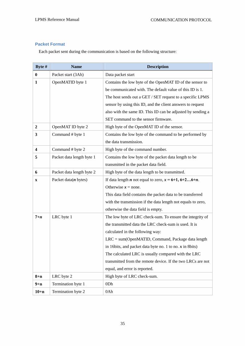
Packet Format
Each packet sent during the communication is based on the following structure:
Byte # Name Description
0 Packet start (3Ah) Data packet start
1 OpenMATID byte 1 Contains the low byte of the OpenMAT ID of the sensor to
be communicated with. The default value of this ID is 1.
The host sends out a GET / SET request to a specific LPMS
sensor by using this ID, and the client answers to request
also with the same ID. This ID can be adjusted by sending a
SET command to the sensor firmware.
2 OpenMAT ID byte 2 High byte of the OpenMAT ID of the sensor.
3 Command # byte 1 Contains the low byte of the command to be performed by
the data transmission.
4 Command # byte 2 High byte of the command number.
5 Packet data length byte 1 Contains the low byte of the packet data length to be
transmitted in the packet data field.
6 Packet data length byte 2 High byte of the data length to be transmitted.
x
Packet data(n bytes)
If data length n not equal to zero, x = 6+1, 6+2…6+n.
Otherwise x = none.
This data field contains the packet data to be transferred
with the transmission if the data length not equals to zero,
otherwise the data field is empty.
7+n LRC byte 1 The low byte of LRC check-sum. To ensure the integrity of
the transmitted data the LRC check-sum is used. It is
calculated in the following way:
LRC = sum(OpenMATID, Command, Package data length
in 16bits, and packet data byte no. 1 to no. x in 8bits)
The calculated LRC is usually compared with the LRC
transmitted from the remote device. If the two LRCs are not
equal, and error is reported.
8+n LRC byte 2 High byte of LRC check-sum.
9+n Termination byte 1 0Dh
10+n Termination byte 2 0Ah
LPMS Reference Manual
36
COMMUNICATION PROTOCOL
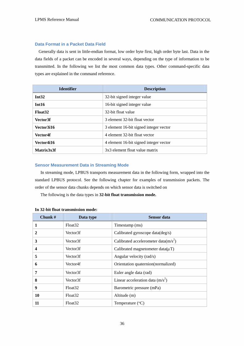
Data Format in a Packet Data Field
Generally data is sent in little-endian format, low order byte first, high order byte last. Data in the
data fields of a packet can be encoded in several ways, depending on the type of information to be
transmitted. In the following we list the most common data types. Other command-specific data
types are explained in the command reference.
Identifier Description
Int32 32-bit signed integer value
Int16 16-bit signed integer value
Float32 32-bit float value
Vector3f 3 element 32-bit float vector
Vector3i16 3 element 16-bit signed integer vector
Vector4f 4 element 32-bit float vector
Vector4i16 4 element 16-bit signed integer vector
Matrix3x3f 3x3 element float value matrix
Sensor Measurement Data in Streaming Mode
In streaming mode, LPBUS transports measurement data in the following form, wrapped into the
standard LPBUS protocol. See the following chapter for examples of transmission packets. The
order of the sensor data chunks depends on which sensor data is switched on
The following is the data types in 32-bit float transmission mode.
In 32-bit float transmission mode:
Chunk # Data type Sensor data
1 Float32 Timestamp (ms)
2 Vector3f Calibrated gyroscope data(deg/s)
3 Vector3f Calibrated accelerometer data(m/s2)
4 Vector3f Calibrated magnetometer data(T)
5 Vector3f Angular velocity (rad/s)
6 Vector4f Orientation quaternion(normalized)
7 Vector3f Euler angle data (rad)
8 Vector3f Linear acceleration data (m/s2)
9 Float32 Barometric pressure (mPa)
10 Float32 Altitude (m)
11 Float32 Temperature (°C)
LPMS Reference Manual
37
COMMUNICATION PROTOCOL
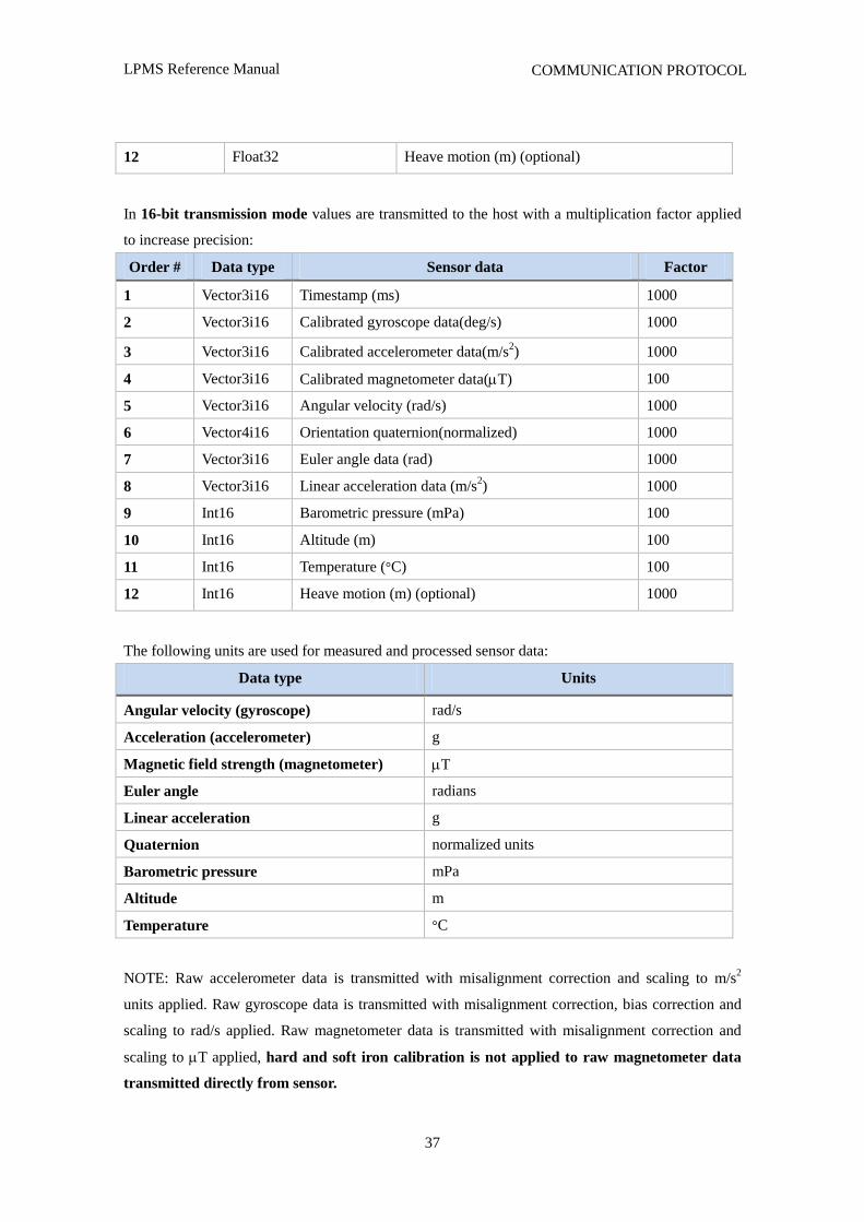
12 Float32 Heave motion (m) (optional)
In 16-bit transmission mode values are transmitted to the host with a multiplication factor applied
to increase precision:
Order # Data type Sensor data Factor
1 Vector3i16 Timestamp (ms) 1000
2 Vector3i16 Calibrated gyroscope data(deg/s) 1000
3 Vector3i16 Calibrated accelerometer data(m/s2) 1000
4 Vector3i16 Calibrated magnetometer data(T) 100
5 Vector3i16 Angular velocity (rad/s) 1000
6 Vector4i16 Orientation quaternion(normalized) 1000
7 Vector3i16 Euler angle data (rad) 1000
8 Vector3i16 Linear acceleration data (m/s2) 1000
9 Int16 Barometric pressure (mPa) 100
10 Int16 Altitude (m) 100
11 Int16 Temperature (°C) 100
12 Int16 Heave motion (m) (optional) 1000
The following units are used for measured and processed sensor data:
Data type Units
Angular velocity (gyroscope) rad/s
Acceleration (accelerometer) g
Magnetic field strength (magnetometer) T
Euler angle radians
Linear acceleration g
Quaternion normalized units
Barometric pressure mPa
Altitude m
Temperature °C
NOTE: Raw accelerometer data is transmitted with misalignment correction and scaling to m/s2
units applied. Raw gyroscope data is transmitted with misalignment correction, bias correction and
scaling to rad/s applied. Raw magnetometer data is transmitted with misalignment correction and
scaling to T applied, hard and soft iron calibration is not applied to raw magnetometer data
transmitted directly from sensor.
LPMS Reference Manual
38
COMMUNICATION PROTOCOL
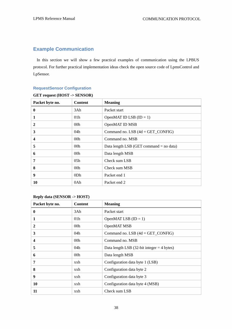
Example Communication
In this section we will show a few practical examples of communication using the LPBUS
protocol. For further practical implementation ideas check the open source code of LpmsControl and
LpSensor.
RequestSensor Configuration
GET request (HOST -> SENSOR)
Packet byte no. Content Meaning
0 3Ah Packet start
1 01h OpenMAT ID LSB (ID = 1)
2 00h OpenMAT ID MSB
3 04h Command no. LSB (4d = GET_CONFIG)
4 00h Command no. MSB
5 00h Data length LSB (GET command = no data)
6 00h Data length MSB
7 05h Check sum LSB
8 00h Check sum MSB
9 0Dh Packet end 1
10 0Ah Packet end 2
Reply data (SENSOR -> HOST)
Packet byte no. Content Meaning
0 3Ah Packet start
1 01h OpenMAT LSB (ID = 1)
2 00h OpenMAT MSB
3 04h Command no. LSB (4d = GET_CONFIG)
4 00h Command no. MSB
5 04h Data length LSB (32-bit integer = 4 bytes)
6 00h Data length MSB
7 xxh Configuration data byte 1 (LSB)
8 xxh Configuration data byte 2
9 xxh Configuration data byte 3
10 xxh Configuration data byte 4 (MSB)
11 xxh Check sum LSB
LPMS Reference Manual
39
COMMUNICATION PROTOCOL
12 xxh Check sum MSB
13 0Dh Packet end 1
14 0Ah Packet end 2
xx = Value depends on the current sensor configuration.
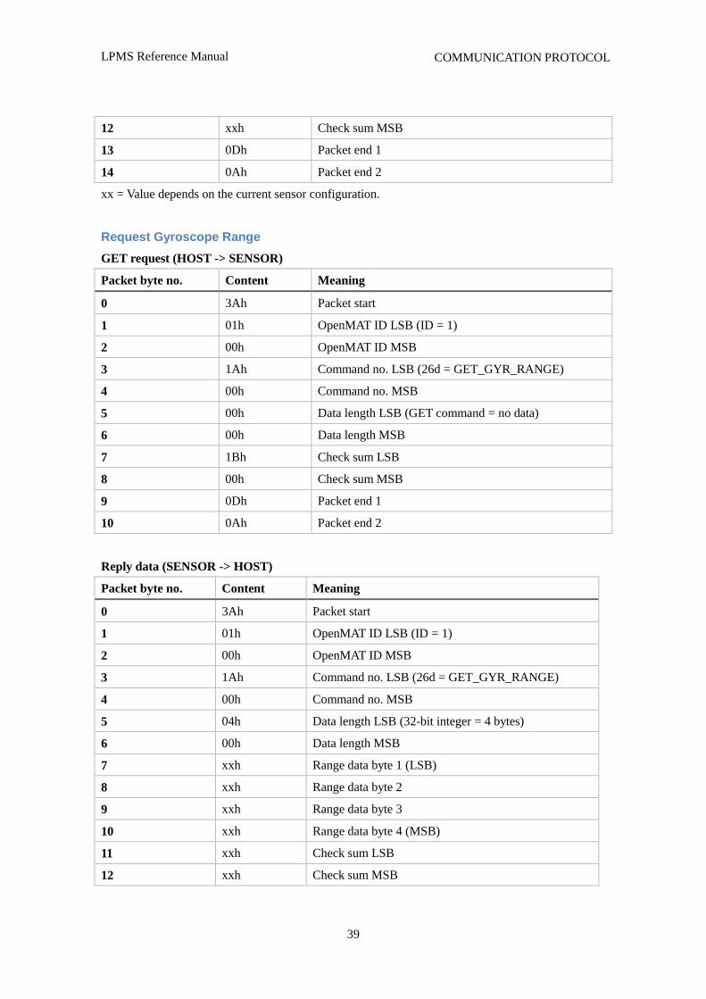
Request Gyroscope Range
GET request (HOST -> SENSOR)
Packet byte no. Content Meaning
0 3Ah Packet start
1 01h OpenMAT ID LSB (ID = 1)
2 00h OpenMAT ID MSB
3 1Ah Command no. LSB (26d = GET_GYR_RANGE)
4 00h Command no. MSB
5 00h Data length LSB (GET command = no data)
6 00h Data length MSB
7 1Bh Check sum LSB
8 00h Check sum MSB
9 0Dh Packet end 1
10 0Ah Packet end 2
Reply data (SENSOR -> HOST)
Packet byte no. Content Meaning
0 3Ah Packet start
1 01h OpenMAT ID LSB (ID = 1)
2 00h OpenMAT ID MSB
3 1Ah Command no. LSB (26d = GET_GYR_RANGE)
4 00h Command no. MSB
5 04h Data length LSB (32-bit integer = 4 bytes)
6 00h Data length MSB
7 xxh Range data byte 1 (LSB)
8 xxh Range data byte 2
9 xxh Range data byte 3
10 xxh Range data byte 4 (MSB)
11 xxh Check sum LSB
12 xxh Check sum MSB
LPMS Reference Manual
40
COMMUNICATION PROTOCOL
13 0Dh Packet end 1
14 0Ah Packet end 2
xx = Value depends on the current sensor configuration.
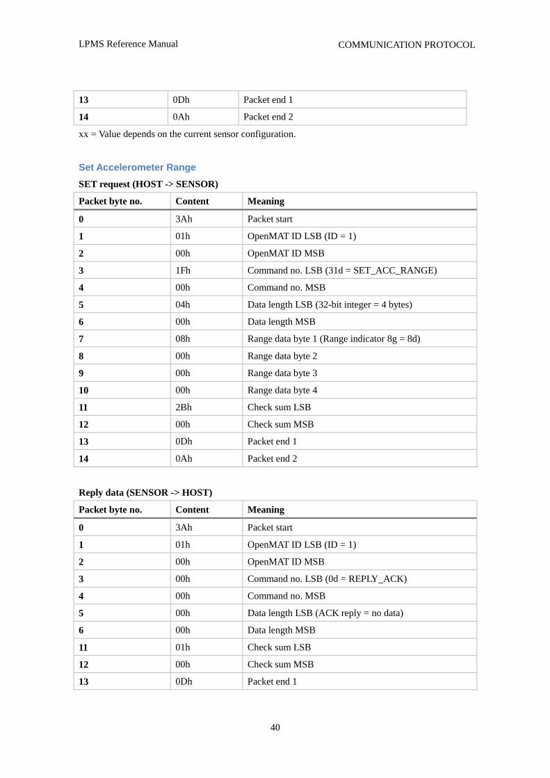
Set Accelerometer Range
SET request (HOST -> SENSOR)
Packet byte no. Content Meaning
0 3Ah Packet start
1 01h OpenMAT ID LSB (ID = 1)
2 00h OpenMAT ID MSB
3 1Fh Command no. LSB (31d = SET_ACC_RANGE)
4 00h Command no. MSB
5 04h Data length LSB (32-bit integer = 4 bytes)
6 00h Data length MSB
7 08h Range data byte 1 (Range indicator 8g = 8d)
8 00h Range data byte 2
9 00h Range data byte 3
10 00h Range data byte 4
11 2Bh Check sum LSB
12 00h Check sum MSB
13 0Dh Packet end 1
14 0Ah Packet end 2
Reply data (SENSOR -> HOST)
Packet byte no. Content Meaning
0 3Ah Packet start
1 01h OpenMAT ID LSB (ID = 1)
2 00h OpenMAT ID MSB
3 00h Command no. LSB (0d = REPLY_ACK)
4 00h Command no. MSB
5 00h Data length LSB (ACK reply = no data)
6 00h Data length MSB
11 01h Check sum LSB
12 00h Check sum MSB
13 0Dh Packet end 1
LPMS Reference Manual
41
COMMUNICATION PROTOCOL
14 0Ah Packet end 2
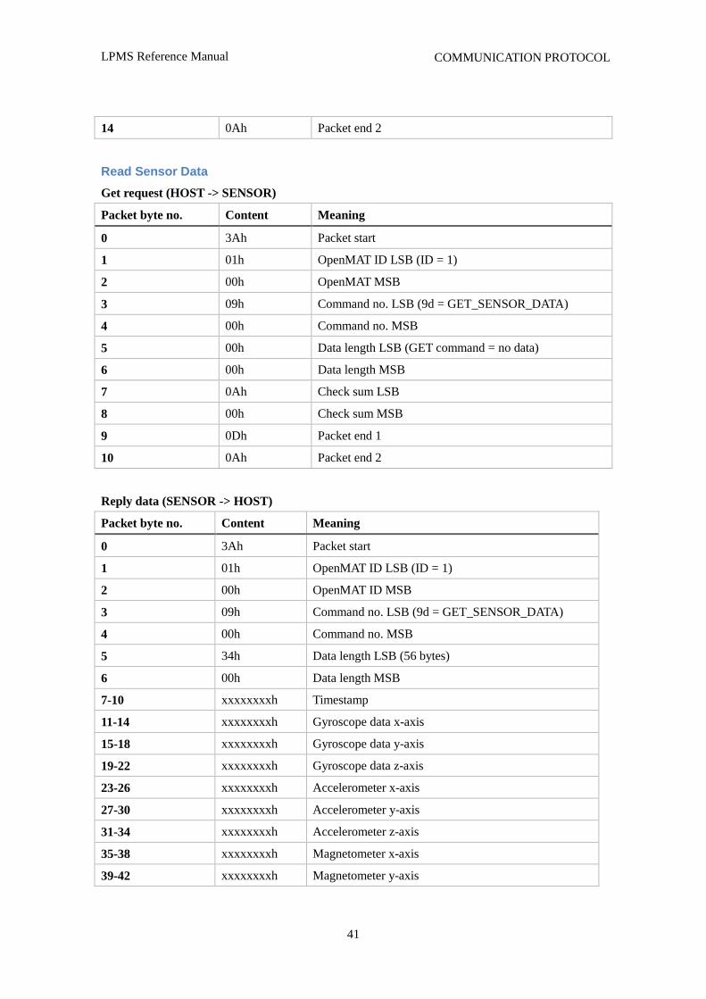
Read Sensor Data
Get request (HOST -> SENSOR)
Packet byte no. Content Meaning
0 3Ah Packet start
1 01h OpenMAT ID LSB (ID = 1)
2 00h OpenMAT MSB
3 09h Command no. LSB (9d = GET_SENSOR_DATA)
4 00h Command no. MSB
5 00h Data length LSB (GET command = no data)
6 00h Data length MSB
7 0Ah Check sum LSB
8 00h Check sum MSB
9 0Dh Packet end 1
10 0Ah Packet end 2
Reply data (SENSOR -> HOST)
Packet byte no. Content Meaning
0 3Ah Packet start
1 01h OpenMAT ID LSB (ID = 1)
2 00h OpenMAT ID MSB
3 09h Command no. LSB (9d = GET_SENSOR_DATA)
4 00h Command no. MSB
5 34h Data length LSB (56 bytes)
6 00h Data length MSB
7-10 xxxxxxxxh Timestamp
11-14 xxxxxxxxh Gyroscope data x-axis
15-18 xxxxxxxxh Gyroscope data y-axis
19-22 xxxxxxxxh Gyroscope data z-axis
23-26 xxxxxxxxh Accelerometer x-axis
27-30 xxxxxxxxh Accelerometer y-axis
31-34 xxxxxxxxh Accelerometer z-axis
35-38 xxxxxxxxh Magnetometer x-axis
39-42 xxxxxxxxh Magnetometer y-axis
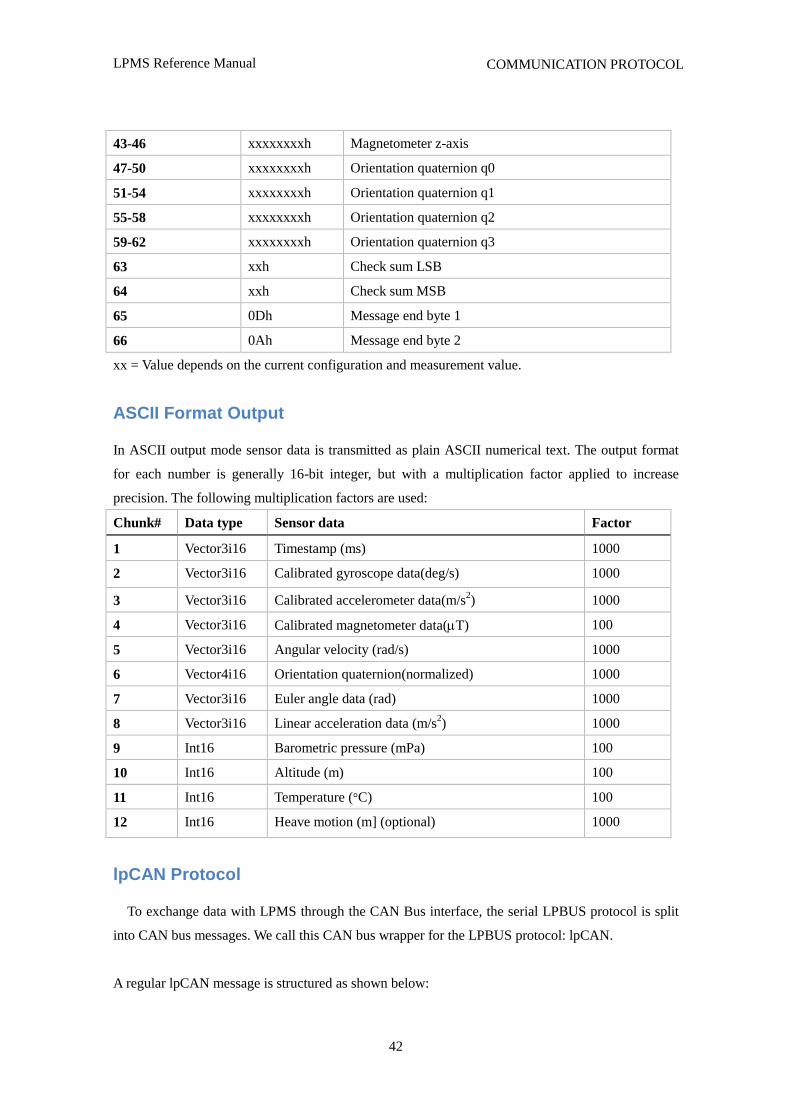
LPMS Reference Manual
42
COMMUNICATION PROTOCOL
43-46 xxxxxxxxh Magnetometer z-axis
47-50 xxxxxxxxh Orientation quaternion q0
51-54 xxxxxxxxh Orientation quaternion q1
55-58 xxxxxxxxh Orientation quaternion q2
59-62 xxxxxxxxh Orientation quaternion q3
63 xxh Check sum LSB
64 xxh Check sum MSB
65 0Dh Message end byte 1
66 0Ah Message end byte 2
xx = Value depends on the current configuration and measurement value.
ASCII Format Output
In ASCII output mode sensor data is transmitted as plain ASCII numerical text. The output format
for each number is generally 16-bit integer, but with a multiplication factor applied to increase
precision. The following multiplication factors are used:
Chunk# Data type Sensor data Factor
1 Vector3i16 Timestamp (ms) 1000
2 Vector3i16 Calibrated gyroscope data(deg/s) 1000
3 Vector3i16 Calibrated accelerometer data(m/s2) 1000
4 Vector3i16 Calibrated magnetometer data(T) 100
5 Vector3i16 Angular velocity (rad/s) 1000
6 Vector4i16 Orientation quaternion(normalized) 1000
7 Vector3i16 Euler angle data (rad) 1000
8 Vector3i16 Linear acceleration data (m/s2) 1000
9 Int16 Barometric pressure (mPa) 100
10 Int16 Altitude (m) 100
11 Int16 Temperature (°C) 100
12 Int16 Heave motion (m] (optional) 1000
lpCAN Protocol
To exchange data with LPMS through the CAN Bus interface, the serial LPBUS protocol is split
into CAN bus messages. We call this CAN bus wrapper for the LPBUS protocol: lpCAN.
A regular lpCAN message is structured as shown below:
LPMS Reference Manual
43
COMMUNICATION PROTOCOL
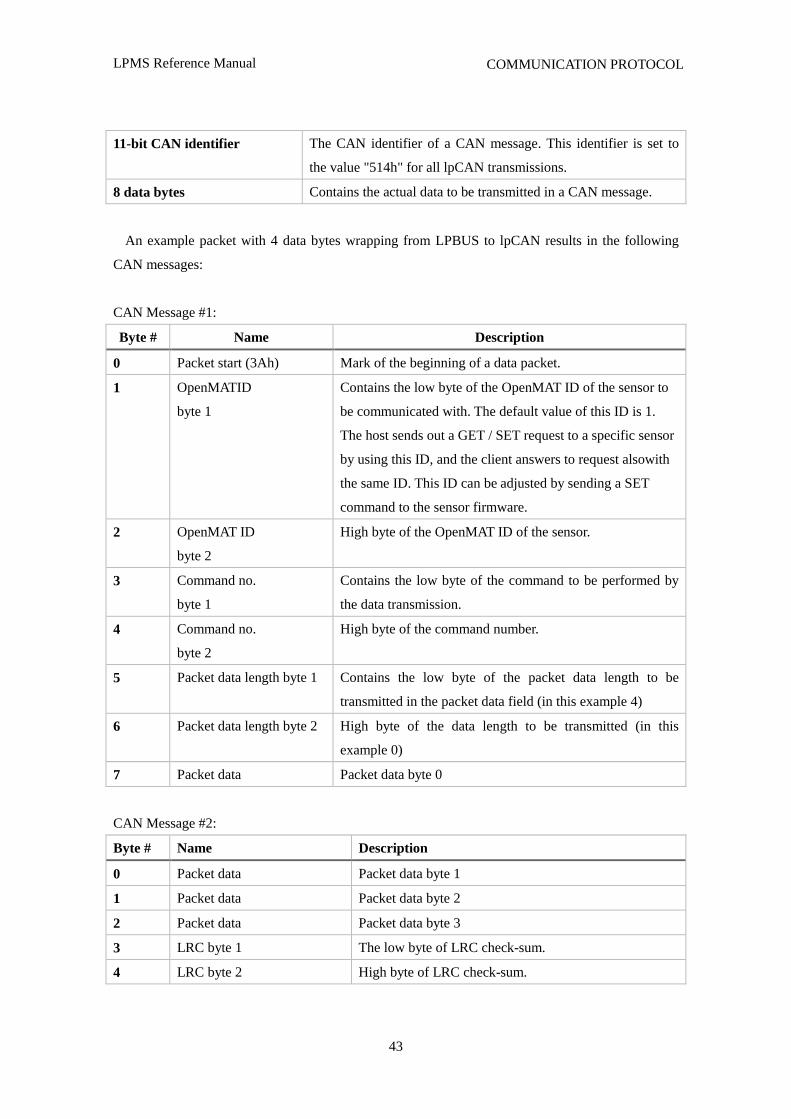
11-bit CAN identifier The CAN identifier of a CAN message. This identifier is set to
the value "514h" for all lpCAN transmissions.
8 data bytes Contains the actual data to be transmitted in a CAN message.
An example packet with 4 data bytes wrapping from LPBUS to lpCAN results in the following
CAN messages:
CAN Message #1:
Byte # Name Description
0 Packet start (3Ah) Mark of the beginning of a data packet.
1 OpenMATID
byte 1
Contains the low byte of the OpenMAT ID of the sensor to
be communicated with. The default value of this ID is 1.
The host sends out a GET / SET request to a specific sensor
by using this ID, and the client answers to request alsowith
the same ID. This ID can be adjusted by sending a SET
command to the sensor firmware.
2 OpenMAT ID
byte 2
High byte of the OpenMAT ID of the sensor.
3 Command no.
byte 1
Contains the low byte of the command to be performed by
the data transmission.
4 Command no.
byte 2
High byte of the command number.
5 Packet data length byte 1 Contains the low byte of the packet data length to be
transmitted in the packet data field (in this example 4)
6 Packet data length byte 2 High byte of the data length to be transmitted (in this
example 0)
7 Packet data Packet data byte 0
CAN Message #2:
Byte # Name Description
0 Packet data Packet data byte 1
1 Packet data Packet data byte 2
2 Packet data Packet data byte 3
3 LRC byte 1 The low byte of LRC check-sum.
4 LRC byte 2 High byte of LRC check-sum.

LPMS Reference Manual
44
COMMUNICATION PROTOCOL
5 Termination byte 1 0Dh
6 Termination byte 2 0Ah
7 Not used 0
The number of messages needed to contain the data depends on the length of the data to be
transmitted. Each CAN message is 8 bytes long. Unused bytes of a message are filled with 0.
CANopen and Sequential CAN Protocol
In CANopen and sequential CAN transmission mode, two or more output words of measurement
data can be assigned to a CAN channel. In sequential CAN mode the channel addressing can be
individually controlled. In CANopen mode, 4 TPDO (Transmission Data Process Object) messages
and a heartbeat message are transmitted. Sensor data is assigned to specific messages either using the
LpmsControl application or direct LPBUS communication.
Data is continuously sent from the sensor to the host with the streaming frequency selected in the
LpmsControl application at the selected baudrate. The data to be transmitted can be selected to
adjust the bus bandwidth used by the LPMS system.
NOTE: In CANopen mode a heartbeat message is transmitted with a frequency between 0.1 Hz and
2 Hz.
The format of CANopen and Sequential CAN bus messages is controlled by the following
parameters:
Channel mode
Value mode
Start ID:
IMU ID
In CANopen mode, the message base address is calculated in the following way:
Base CAN ID = Start ID+ IMU ID
In sequential CAN mode, the message base address is calculated in the following way:
Base CAN ID = Start ID + (IMU ID - 1)*8
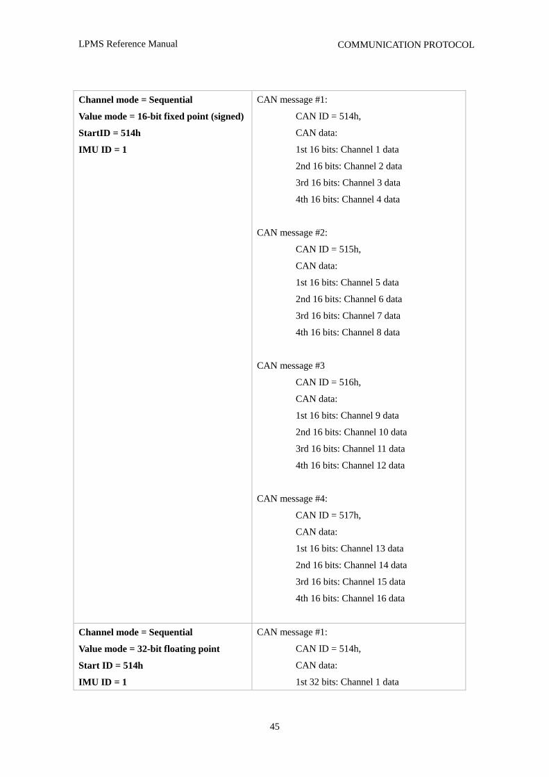
Therefore, using these parameters the following message formats can be adjusted:
Parameter settings Resulting channel message setup
LPMS Reference Manual
45
COMMUNICATION PROTOCOL
Channel mode = Sequential
Value mode = 16-bit fixed point (signed)
StartID = 514h
IMU ID = 1
CAN message #1:
CAN ID = 514h,
CAN data:
1st 16 bits: Channel 1 data
2nd 16 bits: Channel 2 data
3rd 16 bits: Channel 3 data
4th 16 bits: Channel 4 data
CAN message #2:
CAN ID = 515h,
CAN data:
1st 16 bits: Channel 5 data
2nd 16 bits: Channel 6 data
3rd 16 bits: Channel 7 data
4th 16 bits: Channel 8 data
CAN message #3
CAN ID = 516h,
CAN data:
1st 16 bits: Channel 9 data
2nd 16 bits: Channel 10 data
3rd 16 bits: Channel 11 data
4th 16 bits: Channel 12 data
CAN message #4:
CAN ID = 517h,
CAN data:
1st 16 bits: Channel 13 data
2nd 16 bits: Channel 14 data
3rd 16 bits: Channel 15 data
4th 16 bits: Channel 16 data
Channel mode = Sequential
Value mode = 32-bit floating point
Start ID = 514h
IMU ID = 1
CAN message #1:
CAN ID = 514h,
CAN data:
1st 32 bits: Channel 1 data
LPMS Reference Manual
46
COMMUNICATION PROTOCOL
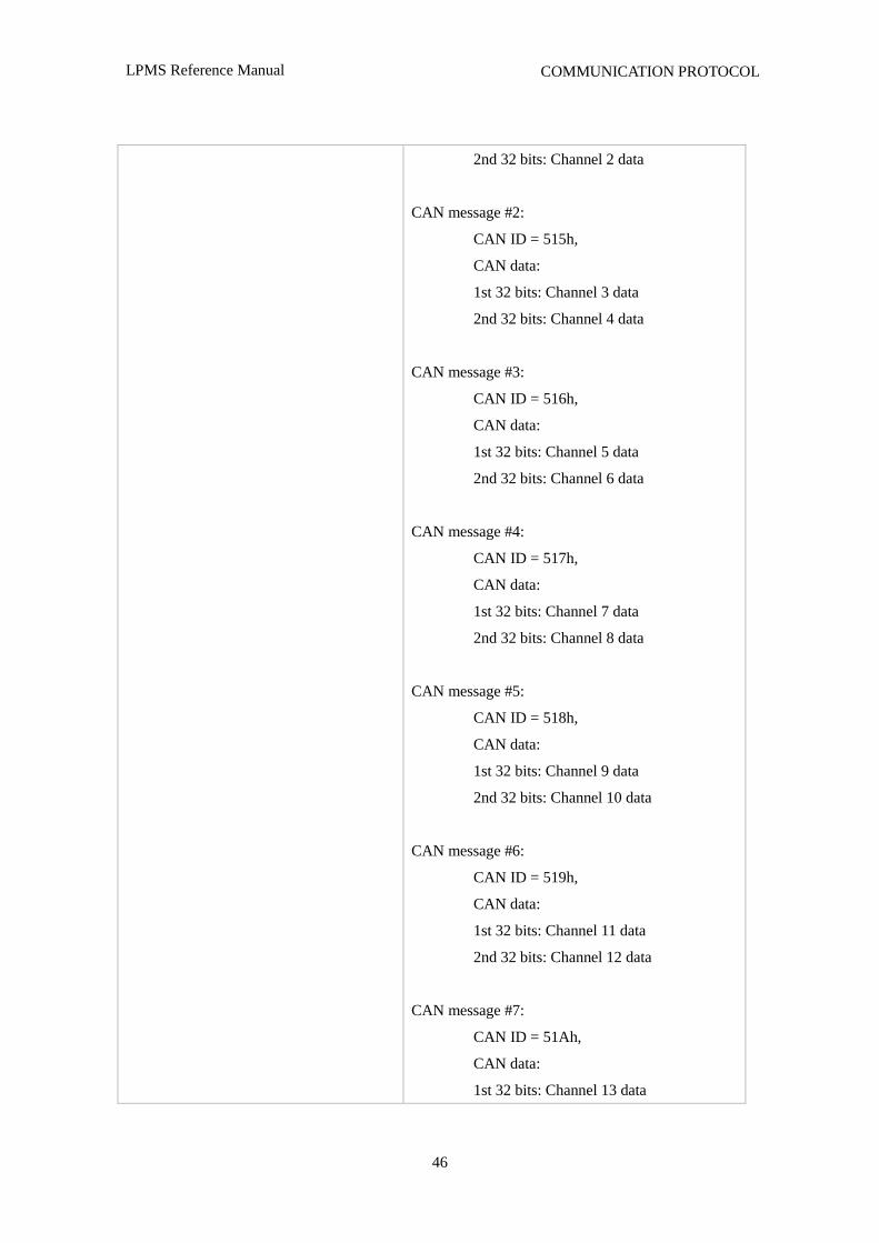
2nd 32 bits: Channel 2 data
CAN message #2:
CAN ID = 515h,
CAN data:
1st 32 bits: Channel 3 data
2nd 32 bits: Channel 4 data
CAN message #3:
CAN ID = 516h,
CAN data:
1st 32 bits: Channel 5 data
2nd 32 bits: Channel 6 data
CAN message #4:
CAN ID = 517h,
CAN data:
1st 32 bits: Channel 7 data
2nd 32 bits: Channel 8 data
CAN message #5:
CAN ID = 518h,
CAN data:
1st 32 bits: Channel 9 data
2nd 32 bits: Channel 10 data
CAN message #6:
CAN ID = 519h,
CAN data:
1st 32 bits: Channel 11 data
2nd 32 bits: Channel 12 data
CAN message #7:
CAN ID = 51Ah,
CAN data:
1st 32 bits: Channel 13 data
LPMS Reference Manual
47
COMMUNICATION PROTOCOL
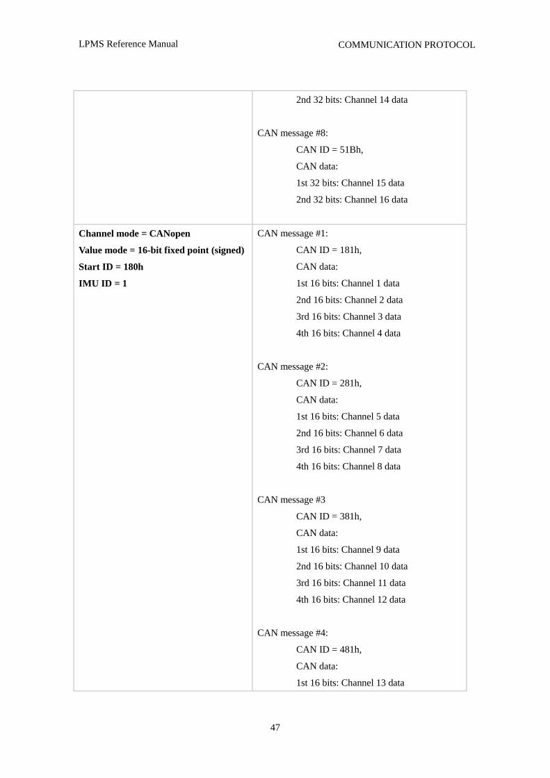
2nd 32 bits: Channel 14 data
CAN message #8:
CAN ID = 51Bh,
CAN data:
1st 32 bits: Channel 15 data
2nd 32 bits: Channel 16 data
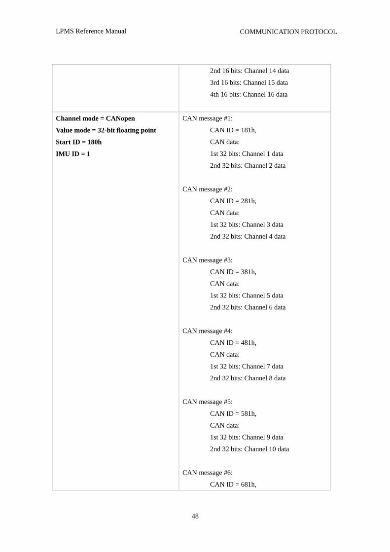
Channel mode = CANopen
Value mode = 16-bit fixed point (signed)
Start ID = 180h
IMU ID = 1
CAN message #1:
CAN ID = 181h,
CAN data:
1st 16 bits: Channel 1 data
2nd 16 bits: Channel 2 data
3rd 16 bits: Channel 3 data
4th 16 bits: Channel 4 data
CAN message #2:
CAN ID = 281h,
CAN data:
1st 16 bits: Channel 5 data
2nd 16 bits: Channel 6 data
3rd 16 bits: Channel 7 data
4th 16 bits: Channel 8 data
CAN message #3
CAN ID = 381h,
CAN data:
1st 16 bits: Channel 9 data
2nd 16 bits: Channel 10 data
3rd 16 bits: Channel 11 data
4th 16 bits: Channel 12 data
CAN message #4:
CAN ID = 481h,
CAN data:
1st 16 bits: Channel 13 data
LPMS Reference Manual
48
COMMUNICATION PROTOCOL
2nd 16 bits: Channel 14 data
3rd 16 bits: Channel 15 data
4th 16 bits: Channel 16 data
Channel mode = CANopen
Value mode = 32-bit floating point
Start ID = 180h
IMU ID = 1
CAN message #1:
CAN ID = 181h,
CAN data:
1st 32 bits: Channel 1 data
2nd 32 bits: Channel 2 data
CAN message #2:
CAN ID = 281h,
CAN data:
1st 32 bits: Channel 3 data
2nd 32 bits: Channel 4 data
CAN message #3:
CAN ID = 381h,
CAN data:
1st 32 bits: Channel 5 data
2nd 32 bits: Channel 6 data
CAN message #4:
CAN ID = 481h,
CAN data:
1st 32 bits: Channel 7 data
2nd 32 bits: Channel 8 data
CAN message #5:
CAN ID = 581h,
CAN data:
1st 32 bits: Channel 9 data
2nd 32 bits: Channel 10 data
CAN message #6:
CAN ID = 681h,
LPMS Reference Manual
49
COMMUNICATION PROTOCOL
CAN data:
1st 32 bits: Channel 11 data
2nd 32 bits: Channel 12 data
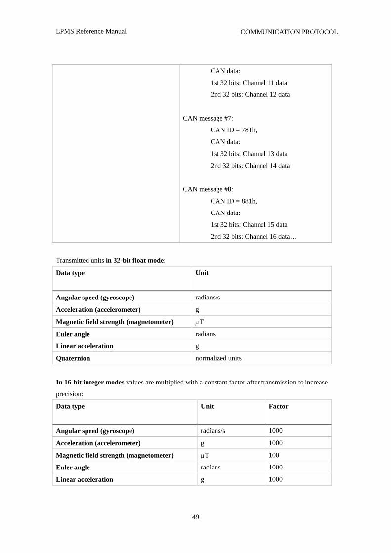
CAN message #7:
CAN ID = 781h,
CAN data:
1st 32 bits: Channel 13 data
2nd 32 bits: Channel 14 data
CAN message #8:
CAN ID = 881h,
CAN data:
1st 32 bits: Channel 15 data
2nd 32 bits: Channel 16 data…
Transmitted units in 32-bit float mode:
Data type Unit
Angular speed (gyroscope) radians/s
Acceleration (accelerometer) g
Magnetic field strength (magnetometer) T
Euler angle radians
Linear acceleration g
Quaternion normalized units
In 16-bit integer modes values are multiplied with a constant factor after transmission to increase
precision:
Data type Unit
Factor
Angular speed (gyroscope) radians/s 1000
Acceleration (accelerometer) g 1000
Magnetic field strength (magnetometer) T 100
Euler angle radians 1000
Linear acceleration g 1000

LPMS Reference Manual
50
COMMUNICATION PROTOCOL
Quaternion normalized units 1000
LPMS Reference Manual
51
OpenMAT LIBRARY
VIII. OpenMAT LIBRARY
Overview
Introduction
The OpenMAT (Open motion analysis toolkit) is the software package delivered with an LPMS
device. The package contains the basic hardware device drivers for the sensors, a C++ library to
easily access the functionality of the IMUs and various other examples and utility programs. Except
for our proprietary algorithms the library is open-source. This includes the firmware of the LPMS
devices. OpenMAT consists of the following components:
Core applications
LpSensor: The core library to manage communication with LPMS devices
LpmsControl: An application to control and use LPMS devices
LpMocap: Full-body human motion capture application
Programming examples
LpmsSimpleExample: A simple example on how to use the LpSensor library
LpmsSanAngeles: Virtual reality application using an LPMS device for viewpoint control in a 3D
environment
LpmsBNativeAndroidLibrary: Java application for acquiring data from LPMS-B on an Android
device
Support components
OpenMATInstaller: Script to build a Windows installer based on NSIS
LpSensorCWrapper: C language wrapper for LpSensor
LpSensorCWrapperTest: Simple test application for C language wrapper
LpmsTimingAnalyzer: Analyzes timing consistency of an LPMS
Sensor firmware
LpmsFirmware: Open-source version of the LPMS firmware
LpmsIAP: In-application programmer for the LPMS
OpenMAT is available as binary release and as source code release. If you would like to use the
included applications in their original form, please use the binary release. This is suggested as the
easiest way to start because it allows you to easily test the functionality of your sensor. The source
LPMS Reference Manual
52
OpenMAT LIBRARY
code of OpenMAT is available from the LP-RESEARCH Bitbucket repository:
https://bitbucket.org/lpresearch/openmat
Application Installation under Windows
Please follow the steps below to install an OpenMAT binary release under Windows. The binary
release includes the OpenMAT API pre-compiled for Windows 32-bit.
1. Download the latest OpenMAT installer from
http://www.lp-research.com/support/
2. Start OpenMAT-x.x.x-Setup.exe (x.x.x being the latest version number)
3. Follow the displayed installation instructions
LpmsControl Software Operation
Overview
The LpmsControl application allows users to control various aspects of an LPMS device.In
particular the application has the following core functionality:
List all LPMS devices connected to the system
Connect to up to 256 sensors simultaneously
Adjust all sensor parameters (sensor range etc.).
Set orientation offsets
Initiate accelerometer, gyroscope and magnetometer calibration.
Display the acquired data in real-time either as line graphs or a 3D image
Record data from the sensors to a CSV data file
Play back data from a previously recorded CSV file
Upload new firmware and in-application-programming software to the sensor
GUI Elements
Toolbar Items
The key functionality of LpmsControl can be accessed via the toolbar. See an overview of the
toolbar in Figure 7, Figure 8, Figure 9 and Figure 10.
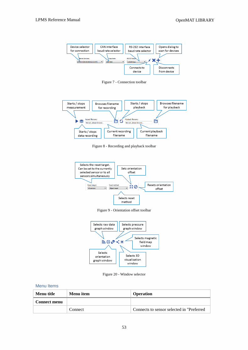
LPMS Reference Manual
53
OpenMAT LIBRARY
Figure 7 - Connection toolbar
Figure 8 - Recording and playback toolbar
Figure 9 - Orientation offset toolbar
Figure 20 - Window selector
Menu Items
Menu title Menu item Operation
Connect menu
Connect Connects to sensor selected in "Preferred
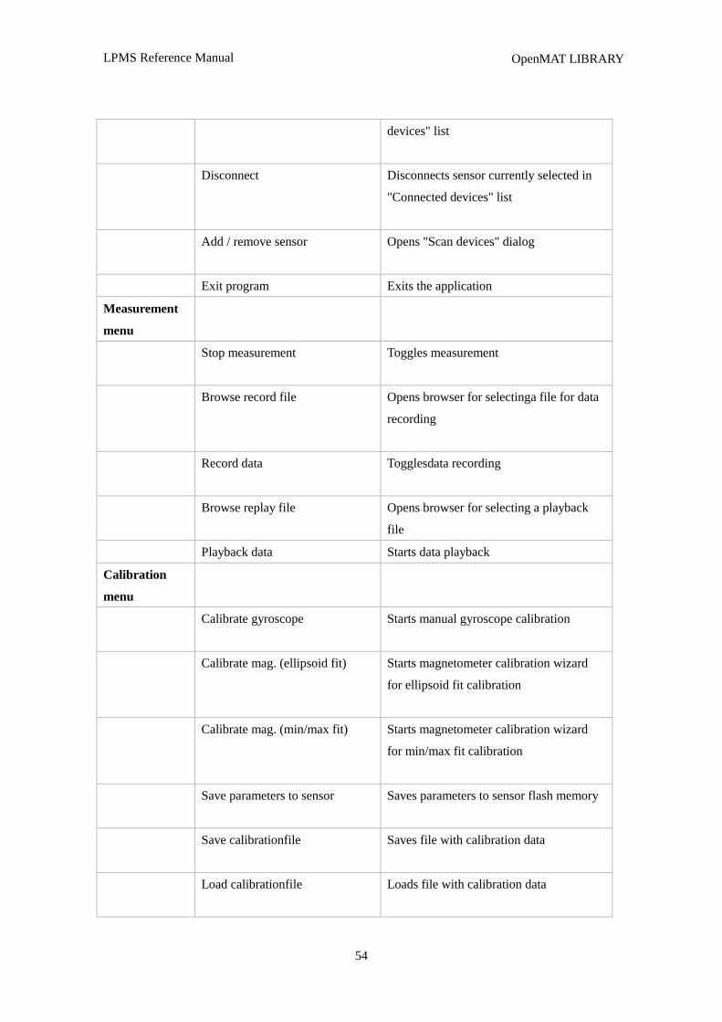
LPMS Reference Manual
54
OpenMAT LIBRARY
devices" list
Disconnect Disconnects sensor currently selected in
"Connected devices" list
Add / remove sensor Opens "Scan devices" dialog
Exit program Exits the application
Measurement
menu
Stop measurement Toggles measurement
Browse record file Opens browser for selectinga file for data
recording
Record data Togglesdata recording
Browse replay file
Opens browser for selecting a playback
file
Playback data Starts data playback
Calibration
menu
Calibrate gyroscope Starts manual gyroscope calibration
Calibrate mag. (ellipsoid fit) Starts magnetometer calibration wizard
for ellipsoid fit calibration
Calibrate mag. (min/max fit) Starts magnetometer calibration wizard
for min/max fit calibration
Save parameters to sensor Saves parameters to sensor flash memory
Save calibrationfile Saves file with calibration data
Load calibrationfile Loads file with calibration data
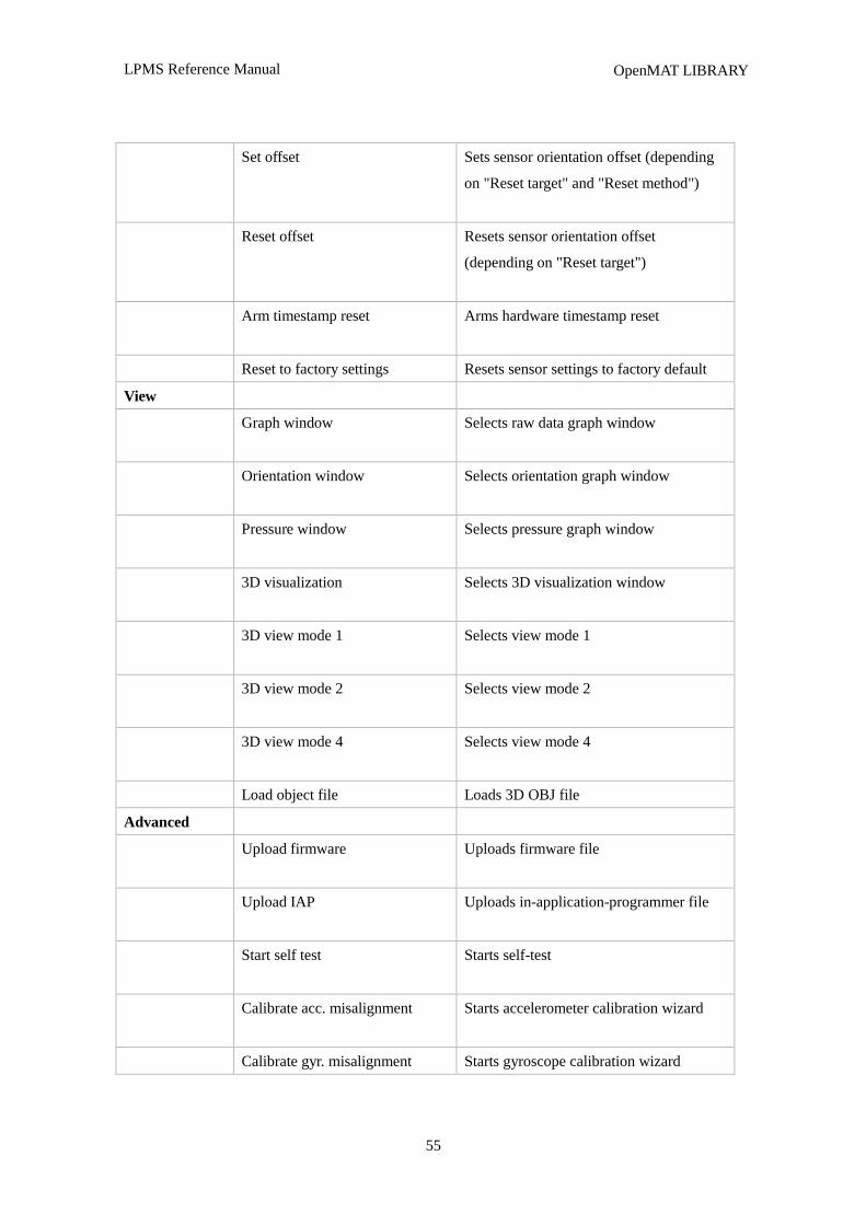
LPMS Reference Manual
55
OpenMAT LIBRARY
Set offset Sets sensor orientation offset (depending
on "Reset target" and "Reset method")
Reset offset Resets sensor orientation offset
(depending on "Reset target")
Arm timestamp reset Arms hardware timestamp reset
Reset to factory settings Resets sensor settings to factory default
View
Graph window Selects raw data graph window
Orientation window Selects orientation graph window
Pressure window Selects pressure graph window
3D visualization Selects 3D visualization window
3D view mode 1 Selects view mode 1
3D view mode 2 Selects view mode 2
3D view mode 4 Selects view mode 4
Load object file Loads 3D OBJ file
Advanced
Upload firmware
Uploads firmware file
Upload IAP
Uploads in-application-programmer file
Start self test
Starts self-test
Calibrate acc. misalignment
Starts accelerometer calibration wizard
Calibrate gyr. misalignment Starts gyroscope calibration wizard
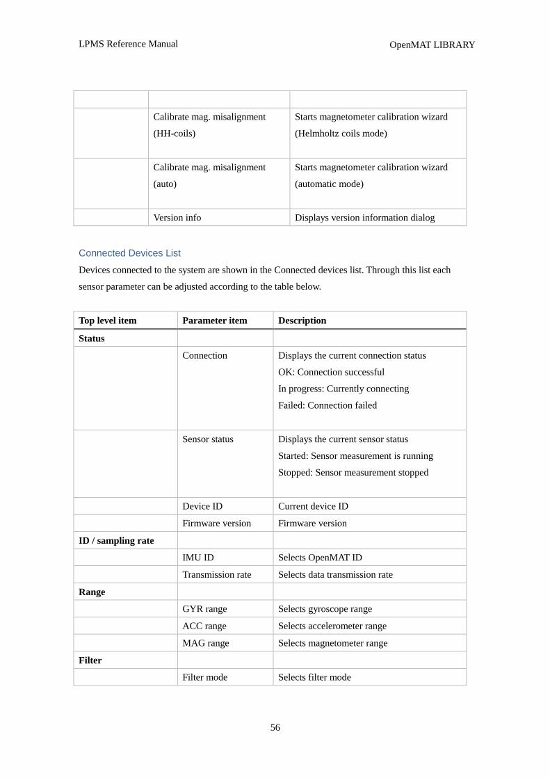
LPMS Reference Manual
56
OpenMAT LIBRARY
Calibrate mag. misalignment
(HH-coils)
Starts magnetometer calibration wizard
(Helmholtz coils mode)
Calibrate mag. misalignment
(auto)
Starts magnetometer calibration wizard
(automatic mode)
Version info Displays version information dialog
Connected Devices List
Devices connected to the system are shown in the Connected devices list. Through this list each
sensor parameter can be adjusted according to the table below.
Top level item Parameter item Description
Status
Connection Displays the current connection status
OK: Connection successful
In progress: Currently connecting
Failed: Connection failed
Sensor status Displays the current sensor status
Started: Sensor measurement is running
Stopped: Sensor measurement stopped
Device ID Current device ID
Firmware version Firmware version
ID / sampling rate
IMU ID Selects OpenMAT ID
Transmission rate Selects data transmission rate
Range
GYR range Selects gyroscope range
ACC range Selects accelerometer range
MAG range Selects magnetometer range
Filter
Filter mode Selects filter mode
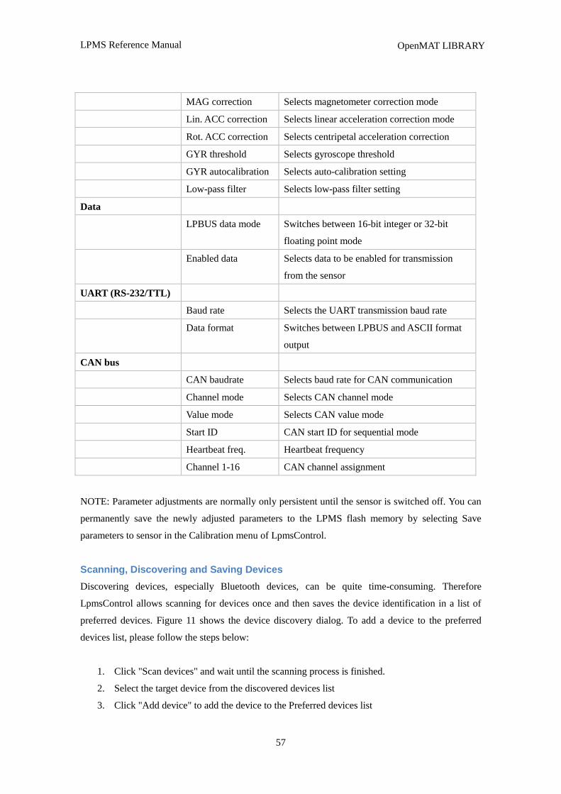
LPMS Reference Manual
57
OpenMAT LIBRARY
MAG correction Selects magnetometer correction mode
Lin. ACC correction Selects linear acceleration correction mode
Rot. ACC correction Selects centripetal acceleration correction
GYR threshold Selects gyroscope threshold
GYR autocalibration Selects auto-calibration setting
Low-pass filter Selects low-pass filter setting
Data
LPBUS data mode Switches between 16-bit integer or 32-bit
floating point mode
Enabled data Selects data to be enabled for transmission
from the sensor
UART (RS-232/TTL)
Baud rate Selects the UART transmission baud rate
Data format Switches between LPBUS and ASCII format
output
CAN bus
CAN baudrate Selects baud rate for CAN communication
Channel mode Selects CAN channel mode
Value mode Selects CAN value mode
Start ID CAN start ID for sequential mode
Heartbeat freq. Heartbeat frequency
Channel 1-16 CAN channel assignment
NOTE: Parameter adjustments are normally only persistent until the sensor is switched off. You can
permanently save the newly adjusted parameters to the LPMS flash memory by selecting Save
parameters to sensor in the Calibration menu of LpmsControl.
Scanning, Discovering and Saving Devices
Discovering devices, especially Bluetooth devices, can be quite time-consuming. Therefore
LpmsControl allows scanning for devices once and then saves the device identification in a list of
preferred devices. Figure 11 shows the device discovery dialog. To add a device to the preferred
devices list, please follow the steps below:
1. Click "Scan devices" and wait until the scanning process is finished.
2. Select the target device from the discovered devices list
3. Click "Add device" to add the device to the Preferred devices list
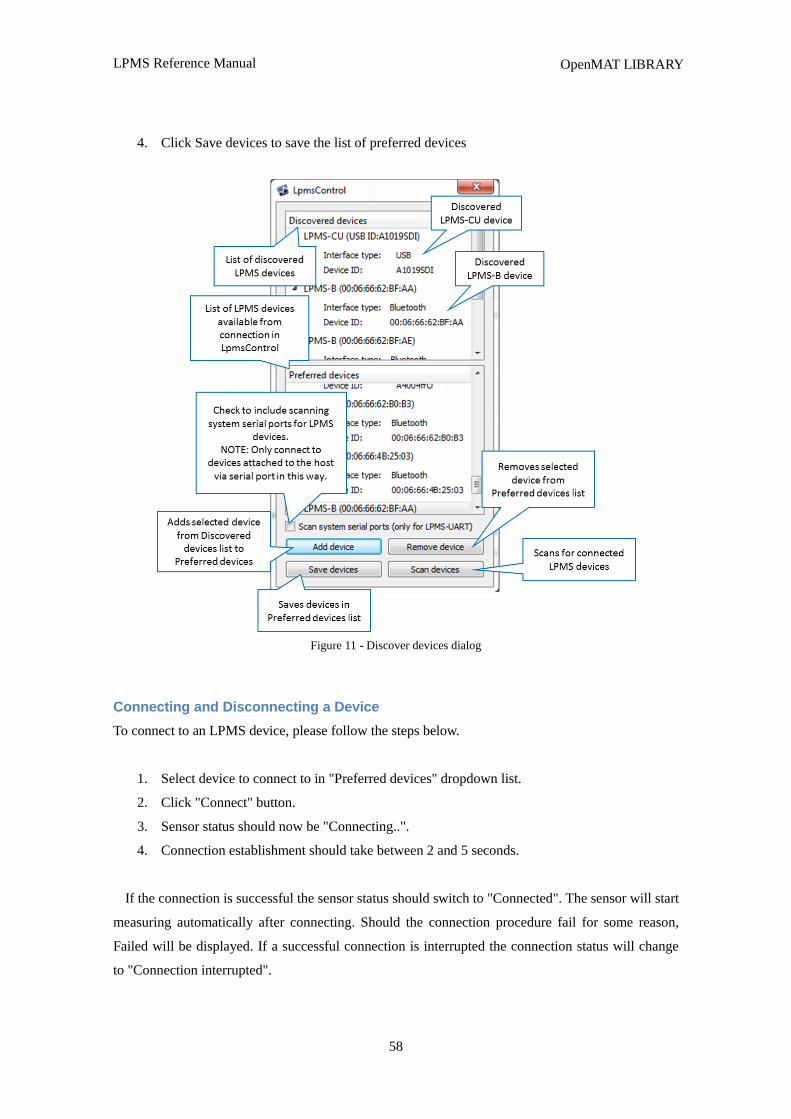
LPMS Reference Manual
58
OpenMAT LIBRARY
4. Click Save devices to save the list of preferred devices
Figure 11 - Discover devices dialog
Connecting and Disconnecting a Device
To connect to an LPMS device, please follow the steps below.
1. Select device to connect to in "Preferred devices" dropdown list.
2. Click "Connect" button.
3. Sensor status should now be "Connecting..".
4. Connection establishment should take between 2 and 5 seconds.
If the connection is successful the sensor status should switch to "Connected". The sensor will start
measuring automatically after connecting. Should the connection procedure fail for some reason,
Failed will be displayed. If a successful connection is interrupted the connection status will change
to "Connection interrupted".
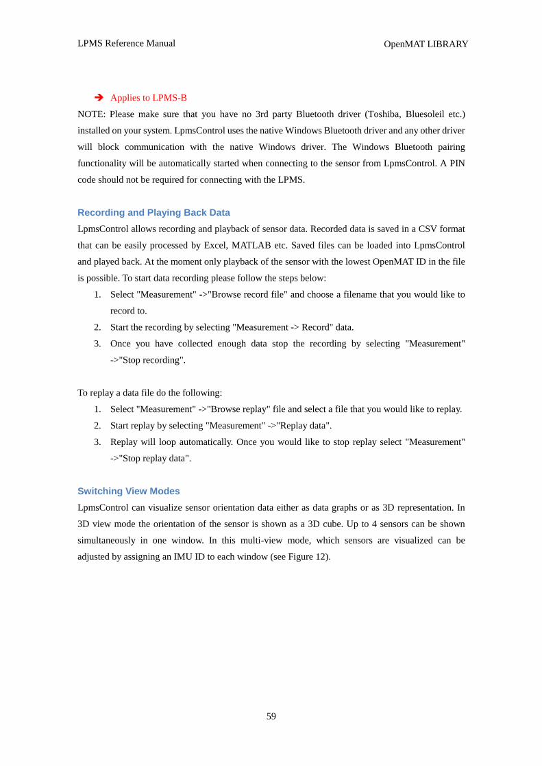
LPMS Reference Manual
59
OpenMAT LIBRARY
Applies to LPMS-B
NOTE: Please make sure that you have no 3rd party Bluetooth driver (Toshiba, Bluesoleil etc.)
installed on your system. LpmsControl uses the native Windows Bluetooth driver and any other driver
will block communication with the native Windows driver. The Windows Bluetooth pairing
functionality will be automatically started when connecting to the sensor from LpmsControl. A PIN
code should not be required for connecting with the LPMS.
Recording and Playing Back Data
LpmsControl allows recording and playback of sensor data. Recorded data is saved in a CSV format
that can be easily processed by Excel, MATLAB etc. Saved files can be loaded into LpmsControl
and played back. At the moment only playback of the sensor with the lowest OpenMAT ID in the file
is possible. To start data recording please follow the steps below:
1. Select "Measurement" ->"Browse record file" and choose a filename that you would like to
record to.
2. Start the recording by selecting "Measurement -> Record" data.
3. Once you have collected enough data stop the recording by selecting "Measurement"
->"Stop recording".
To replay a data file do the following:
1. Select "Measurement" ->"Browse replay" file and select a file that you would like to replay.
2. Start replay by selecting "Measurement" ->"Replay data".
3. Replay will loop automatically. Once you would like to stop replay select "Measurement"
->"Stop replay data".
Switching View Modes
LpmsControl can visualize sensor orientation data either as data graphs or as 3D representation. In
3D view mode the orientation of the sensor is shown as a 3D cube. Up to 4 sensors can be shown
simultaneously in one window. In this multi-view mode, which sensors are visualized can be
adjusted by assigning an IMU ID to each window (see Figure 12).
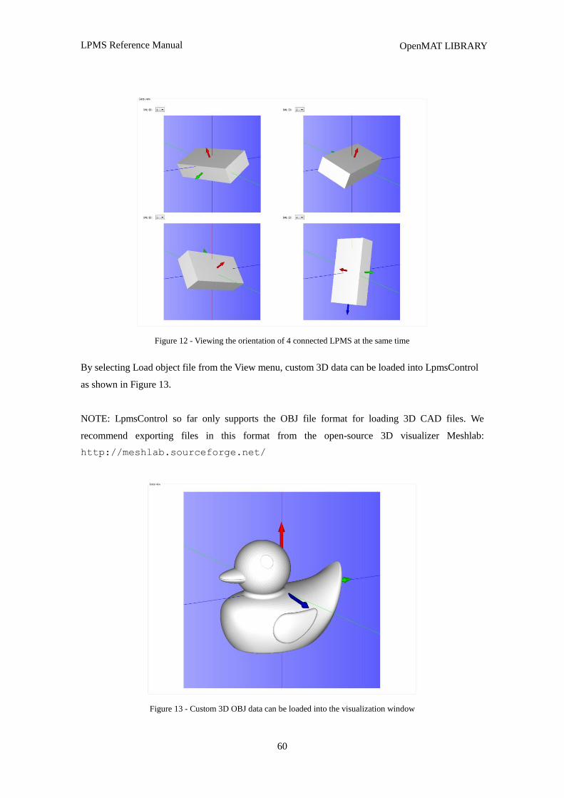
LPMS Reference Manual
60
OpenMAT LIBRARY
Figure 12 - Viewing the orientation of 4 connected LPMS at the same time
By selecting Load object file from the View menu, custom 3D data can be loaded into LpmsControl
as shown in Figure 13.
NOTE: LpmsControl so far only supports the OBJ file format for loading 3D CAD files. We
recommend exporting files in this format from the open-source 3D visualizer Meshlab:
http://meshlab.sourceforge.net/
Figure 13 - Custom 3D OBJ data can be loaded into the visualization window
LPMS Reference Manual
61
OpenMAT LIBRARY
Uploading New Firmware
Please follow the following steps carefully when you are updating the sensor firmware. Invalid
operation might result in an incomplete firmware update and brick the sensor.
1. Start your current LpmsControl software.
2. Connect to the sensor you would like to update.
3. Choose the “Save parameters to file” function from the “Calibration” menu of LpmsControl
to save the current sensor calibration results into a .txt file on your local host system.
4. Select Upload firmware function in the “Advanced” menu.
5. Click OK and select the new firmware file. Be careful that you select the right file which
should be named as LpmsXFirmwareX.X.X.bin (with X being the sensor type identifier and
firmware version).
6. Wait for the upload process to finish. It should take around 30 seconds. At around 15s the
green LED on the sensor should begin to blink rapidly (~10 Hz).
7. Disconnect from the sensor and exit LpmsControl.
8. Now install the new LpmsControl application. The previous LpmsControl application does
not need to be un-installed.
9. Start LpmsControl and connect to your sensor.
10. Choose the “Load parameters fromfile” function from the “Calibration” menu of
LpmsControl to recover the previous sensor calibration results.
11. Choose the “Save parameters”tosensor function from the calibration menu of LpmsControl
to save the previous sensor calibration results into sensor flash.
12. The update is finished. Make sure everything works as expected.
The LpSensor Library
Building Your Application
The LpSensor library contains classes that allow a user to integrate LPMS devices into their own
applications. The standard library is a Windows 32-bit C++ library for MS Visual C++
(express) 2010. Should you require a binary of the library to work on another operating system or
64-bit applications, please contact LP-RESEARCH.
Compiling applications that use the LpSensor library requires the following components:
Header files (usually in C:/OpenMAT/include):
LpmsSensorManagerI.h Contains the interface for the LpmsSensorManager class.
LPMS Reference Manual
62
OpenMAT LIBRARY
LpmsSensorI.h Contains the interface for the LpmsSensor class
ImuData.h Structure for containing output data from a LPMS device
LpmsDefinitions.h Macro definitions for accessing LPMS
DeviceListItem.h Contains the class definition for an element of a LPMS device list
LIB files (usually in C:/OpenMAT/lib/x86):
LpSensorD.lib LpSensor library (Debug version)
LpSensor.lib LpSensor library (Release version)
DLL files (usually in C:/OpenMAT/lib/x86):
LpSensorD.dll LpSensor library (Debug version)
LpSensor.dll LpSensor library (Release version)
PCANBasic.dll PeakCAN library DLL for CAN interface communication (optional).
ftd2xx.dll The FTDI library to communicate with an LPMS over USB.
To compile the application please do the following:
1. Include LpmsSensorManagerI.h.
2. Add LpSensor.lib (or LpSensorD.lib if you are compiling in debug mode) to the link libraries
file list of your application
3. Make sure that you set a path to LpSensor.dll / LpSensorD.dll, PCANBasic.dll (optional) and
ftd2xx.dll so that the runtime file of your application can access them.
4. Build your application.
Important Classes
SensorManager
The sensor manager class wraps a number of LpmsSensor instances into one class, handles device
discovery and device polling. For user applications the following methods are most commonly used.
Please refer to the interface file SensorManagerI.h for more information.
NOTE: An instance of LpmsSensor is returned by the static function
LpmsSensorManagerFactory(). See the example listing in the next section for more information
how to initialize an LpmsSensorManager object.
Method name SensorManager(void)
Parameters none
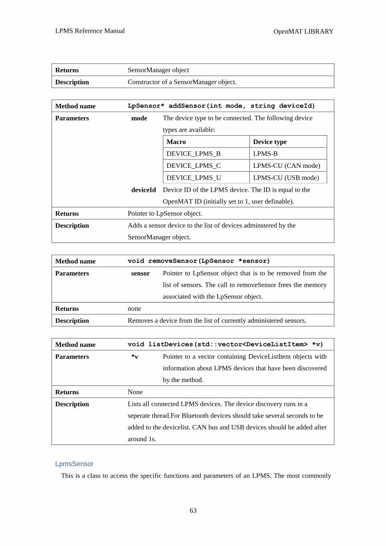
LPMS Reference Manual
63
OpenMAT LIBRARY
Returns SensorManager object
Description Constructor of a SensorManager object.
Method name LpSensor* addSensor(int mode, string deviceId)
Parameters mode The device type to be connected. The following device
types are available:
Macro Device type
DEVICE_LPMS_B LPMS-B
DEVICE_LPMS_C LPMS-CU (CAN mode)
DEVICE_LPMS_U LPMS-CU (USB mode)
deviceId Device ID of the LPMS device. The ID is equal to the
OpenMAT ID (initially set to 1, user definable).
Returns Pointer to LpSensor object.
Description Adds a sensor device to the list of devices adminstered by the
SensorManager object.
Method name void removeSensor(LpSensor *sensor)
Parameters sensor Pointer to LpSensor object that is to be removed from the
list of sensors. The call to removeSensor frees the memory
associated with the LpSensor object.
Returns none
Description Removes a device from the list of currently administered sensors.
Method name void listDevices(std::vector<DeviceListItem> *v)
Parameters *v Pointer to a vector containing DeviceListItem objects with
information about LPMS devices that have been discovered
by the method.
Returns None
Description Lists all connected LPMS devices. The device discovery runs in a
seperate thread.For Bluetooth devices should take several seconds to be
added to the devicelist. CAN bus and USB devices should be added after
around 1s.
LpmsSensor
This is a class to access the specific functions and parameters of an LPMS. The most commonly
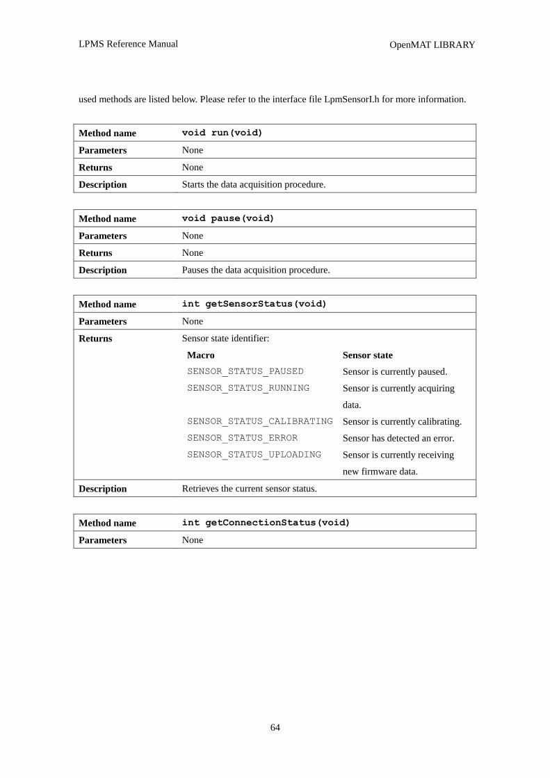
LPMS Reference Manual
64
OpenMAT LIBRARY
used methods are listed below. Please refer to the interface file LpmSensorI.h for more information.
Method name void run(void)
Parameters None
Returns None
Description Starts the data acquisition procedure.
Method name void pause(void)
Parameters None
Returns None
Description Pauses the data acquisition procedure.
Method name int getSensorStatus(void)
Parameters None
Returns Sensor state identifier:
Macro Sensor state
SENSOR_STATUS_PAUSED Sensor is currently paused.
SENSOR_STATUS_RUNNING Sensor is currently acquiring
data.
SENSOR_STATUS_CALIBRATING Sensor is currently calibrating.
SENSOR_STATUS_ERROR Sensor has detected an error.
SENSOR_STATUS_UPLOADING Sensor is currently receiving
new firmware data.
Description Retrieves the current sensor status.
Method name int getConnectionStatus(void)
Parameters None
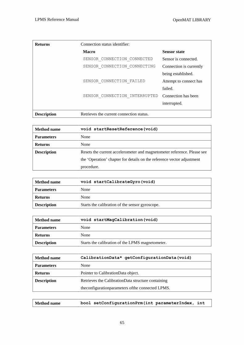
LPMS Reference Manual
65
OpenMAT LIBRARY
Returns Connection status identifier:
Macro Sensor state
SENSOR_CONNECTION_CONNECTED Sensor is connected.
SENSOR_CONNECTION_CONNECTING Connection is currently
being established.
SENSOR_CONNECTION_FAILED Attempt to connect has
failed.
SENSOR_CONNECTION_INTERRUPTED Connection has been
interrupted.
Description Retrieves the current connection status.
Method name void startResetReference(void)
Parameters None
Returns None
Description Resets the current accelerometer and magnetometer reference. Please see
the „Operation‟ chapter for details on the reference vector adjustment
procedure.
Method name void startCalibrateGyro(void)
Parameters None
Returns None
Description Starts the calibration of the sensor gyroscope.
Method name void startMagCalibration(void)
Parameters None
Returns None
Description Starts the calibration of the LPMS magnetometer.
Method name CalibrationData* getConfigurationData(void)
Parameters None
Returns Pointer to CalibrationData object.
Description Retrieves the CalibrationData structure containing
theconfigurationparameters ofthe connected LPMS.
Method name bool setConfigurationPrm(int parameterIndex, int
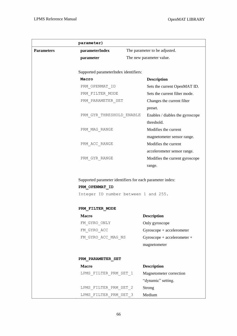
LPMS Reference Manual
66
OpenMAT LIBRARY
parameter)
Parameters parameterIndex The parameter to be adjusted.
parameter The new parameter value.
Supported parameterIndex identifiers:
Macro Description
PRM_OPENMAT_ID Sets the current OpenMAT ID.
PRM_FILTER_MODE Sets the current filter mode.
PRM_PARAMETER_SET Changes the current filter
preset.
PRM_GYR_THRESHOLD_ENABLE Enables / diables the gyroscope
threshold.
PRM_MAG_RANGE Modifies the current
magnetometer sensor range.
PRM_ACC_RANGE Modifies the current
accelerometer sensor range.
PRM_GYR_RANGE Modifies the current gyroscope
range.
Supported parameter identifiers for each parameter index:
PRM_OPENMAT_ID
Integer ID number between 1 and 255.
PRM_FILTER_MODE
Macro Description
FM_GYRO_ONLY Only gyroscope
FM_GYRO_ACC Gyroscope + accelerometer
FM_GYRO_ACC_MAG_NS Gyroscope + accelerometer +
magnetometer
PRM_PARAMETER_SET
Macro Description
LPMS_FILTER_PRM_SET_1 Magnetometer correction
“dynamic” setting.
LPMS_FILTER_PRM_SET_2 Strong
LPMS_FILTER_PRM_SET_3 Medium
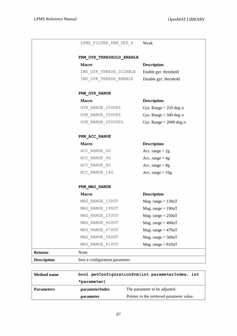
LPMS Reference Manual
67
OpenMAT LIBRARY
LPMS_FILTER_PRM_SET_4 Weak
PRM_GYR_THRESHOLD_ENABLE
Macro Description
IMU_GYR_THRESH_DISABLE Enable gyr. threshold
IMU_GYR_THRESH_ENABLE Disable gyr. thershold
PRM_GYR_RANGE
Macro Description
GYR_RANGE_250DPS Gyr. Range = 250 deg./s
GYR_RANGE_500DPS Gyr. Range = 500 deg./s
GYR_RANGE_2000DPS Gyr. Range = 2000 deg./s
PRM_ACC_RANGE
Macro Description
ACC_RANGE_2G Acc. range = 2g
ACC_RANGE_4G Acc. range = 4g
ACC_RANGE_8G Acc. range = 8g
ACC_RANGE_16G Acc. range = 16g
PRM_MAG_RANGE
Macro Description
MAG_RANGE_130UT Mag. range = 130uT
MAG_RANGE_190UT Mag. range = 190uT
MAG_RANGE_250UT Mag. range = 250uT
MAG_RANGE_400UT Mag. range = 400uT
MAG_RANGE_470UT Mag. range = 470uT
MAG_RANGE_560UT Mag. range = 560uT
MAG_RANGE_810UT Mag. range = 810uT
Returns None
Description Sets a configuration parameter.
Method name bool getConfigurationPrm(int parameterIndex, int
*parameter)
Parameters parameterIndex The parameter to be adjusted.
parameter Pointer to the retrieved parameter value.
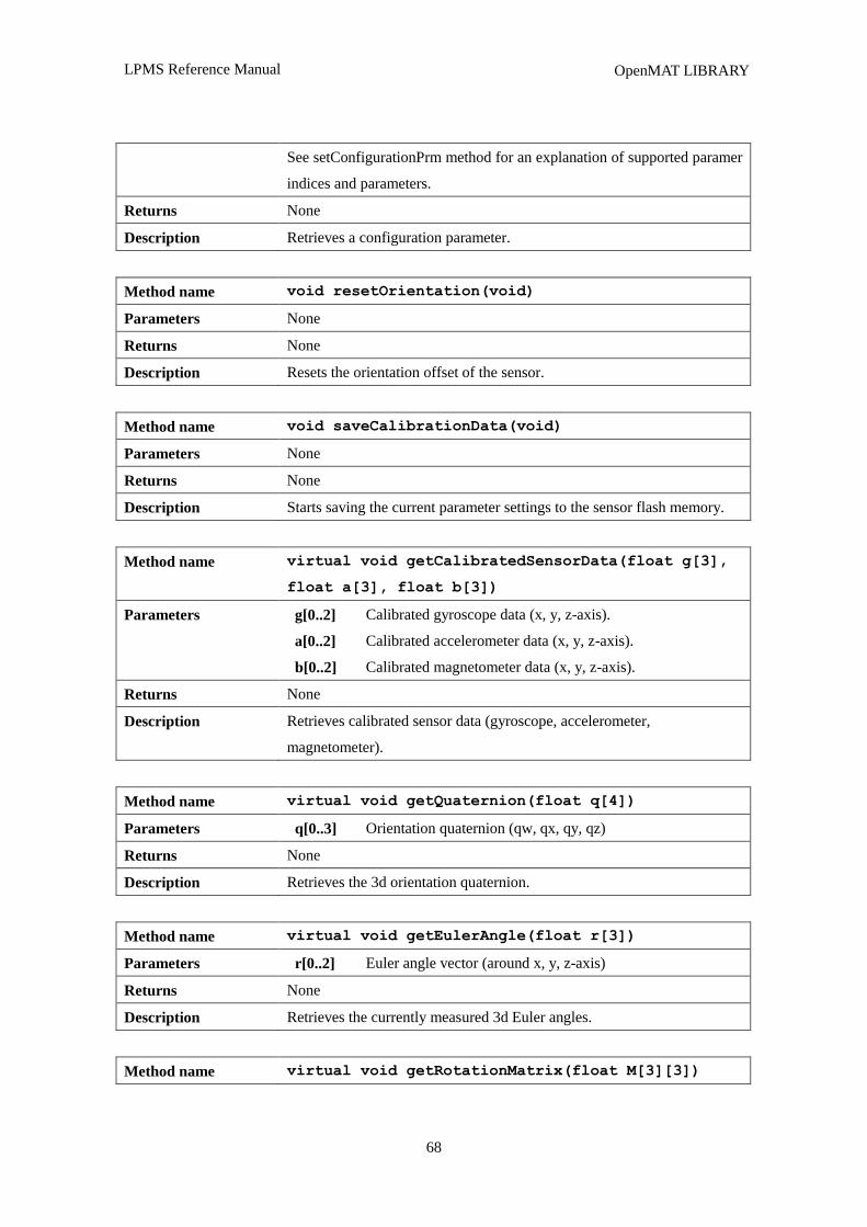
LPMS Reference Manual
68
OpenMAT LIBRARY
See setConfigurationPrm method for an explanation of supported paramer
indices and parameters.
Returns None
Description Retrieves a configuration parameter.
Method name void resetOrientation(void)
Parameters None
Returns None
Description Resets the orientation offset of the sensor.
Method name void saveCalibrationData(void)
Parameters None
Returns None
Description Starts saving the current parameter settings to the sensor flash memory.
Method name virtual void getCalibratedSensorData(float g[3],
float a[3], float b[3])
Parameters g[0..2] Calibrated gyroscope data (x, y, z-axis).
a[0..2] Calibrated accelerometer data (x, y, z-axis).
b[0..2] Calibrated magnetometer data (x, y, z-axis).
Returns None
Description Retrieves calibrated sensor data (gyroscope, accelerometer,
magnetometer).
Method name virtual void getQuaternion(float q[4])
Parameters q[0..3] Orientation quaternion (qw, qx, qy, qz)
Returns None
Description Retrieves the 3d orientation quaternion.
Method name virtual void getEulerAngle(float r[3])
Parameters r[0..2] Euler angle vector (around x, y, z-axis)
Returns None
Description Retrieves the currently measured 3d Euler angles.
Method name virtual void getRotationMatrix(float M[3][3])
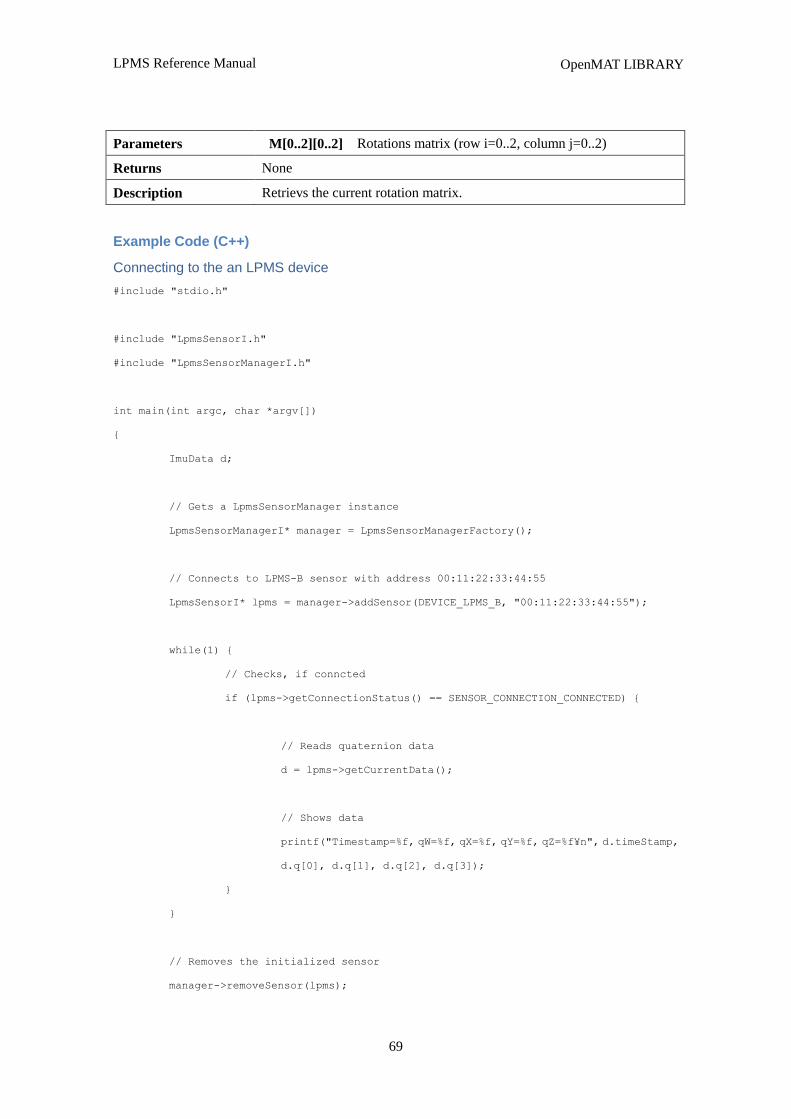
LPMS Reference Manual
69
OpenMAT LIBRARY
Parameters M[0..2][0..2] Rotations matrix (row i=0..2, column j=0..2)
Returns None
Description Retrievs the current rotation matrix.
Example Code (C++)
Connecting to the an LPMS device
#include "stdio.h"
#include "LpmsSensorI.h"
#include "LpmsSensorManagerI.h"
int main(int argc, char *argv[])
{
ImuData d;
// Gets a LpmsSensorManager instance
LpmsSensorManagerI* manager = LpmsSensorManagerFactory();
// Connects to LPMS-B sensor with address 00:11:22:33:44:55
LpmsSensorI* lpms = manager->addSensor(DEVICE_LPMS_B, "00:11:22:33:44:55");
while(1) {
// Checks, if conncted
if (lpms->getConnectionStatus() == SENSOR_CONNECTION_CONNECTED) {
// Reads quaternion data
d = lpms->getCurrentData();
// Shows data
printf("Timestamp=%f, qW=%f, qX=%f, qY=%f, qZ=%f¥n", d.timeStamp,
d.q[0], d.q[1], d.q[2], d.q[3]);
}
}
// Removes the initialized sensor
manager->removeSensor(lpms);
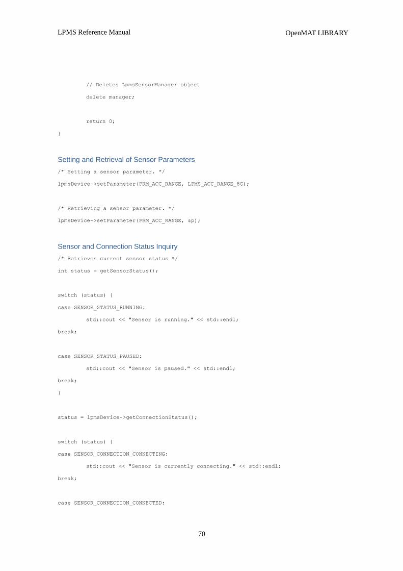
LPMS Reference Manual
70
OpenMAT LIBRARY
// Deletes LpmsSensorManager object
delete manager;
return 0;
}
Setting and Retrieval of Sensor Parameters
/* Setting a sensor parameter. */
lpmsDevice->setParameter(PRM_ACC_RANGE, LPMS_ACC_RANGE_8G);
/* Retrieving a sensor parameter. */
lpmsDevice->setParameter(PRM_ACC_RANGE, &p);
Sensor and Connection Status Inquiry
/* Retrieves current sensor status */
int status = getSensorStatus();
switch (status) {
case SENSOR_STATUS_RUNNING:
std::cout << "Sensor is running." << std::endl;
break;
case SENSOR_STATUS_PAUSED:
std::cout << "Sensor is paused." << std::endl;
break;
}
status = lpmsDevice->getConnectionStatus();
switch (status) {
case SENSOR_CONNECTION_CONNECTING:
std::cout << "Sensor is currently connecting." << std::endl;
break;
case SENSOR_CONNECTION_CONNECTED:

LPMS Reference Manual
71
OpenMAT LIBRARY
std::cout << "Sensor is connected." << std::endl;
break;
}
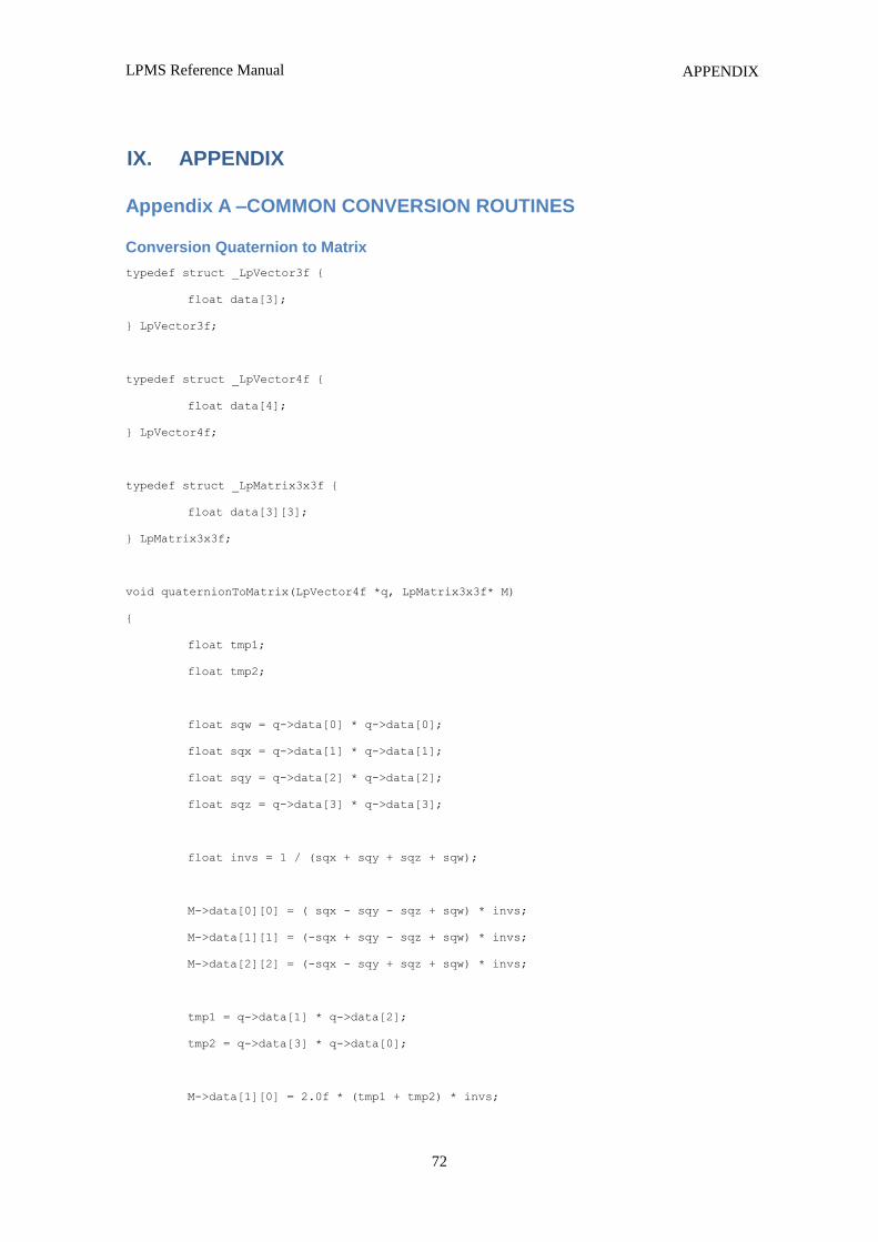
LPMS Reference Manual
72
APPENDIX
IX. APPENDIX
Appendix A –COMMON CONVERSION ROUTINES
Conversion Quaternion to Matrix
typedef struct _LpVector3f {
float data[3];
} LpVector3f;
typedef struct _LpVector4f {
float data[4];
} LpVector4f;
typedef struct _LpMatrix3x3f {
float data[3][3];
} LpMatrix3x3f;
void quaternionToMatrix(LpVector4f *q, LpMatrix3x3f* M)
{
float tmp1;
float tmp2;
float sqw = q->data[0] * q->data[0];
float sqx = q->data[1] * q->data[1];
float sqy = q->data[2] * q->data[2];
float sqz = q->data[3] * q->data[3];
float invs = 1 / (sqx + sqy + sqz + sqw);
M->data[0][0] = ( sqx - sqy - sqz + sqw) * invs;
M->data[1][1] = (-sqx + sqy - sqz + sqw) * invs;
M->data[2][2] = (-sqx - sqy + sqz + sqw) * invs;
tmp1 = q->data[1] * q->data[2];
tmp2 = q->data[3] * q->data[0];
M->data[1][0] = 2.0f * (tmp1 + tmp2) * invs;
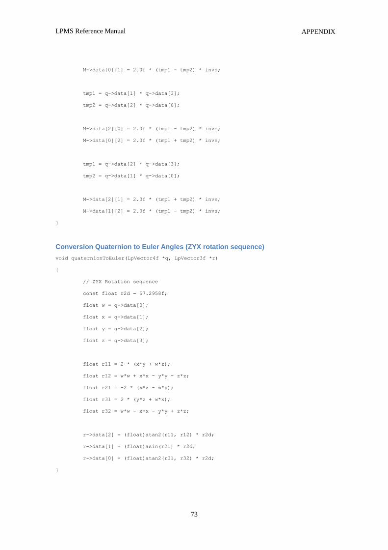
LPMS Reference Manual
73
APPENDIX
M->data[0][1] = 2.0f * (tmp1 - tmp2) * invs;
tmp1 = q->data[1] * q->data[3];
tmp2 = q->data[2] * q->data[0];
M->data[2][0] = 2.0f * (tmp1 - tmp2) * invs;
M->data[0][2] = 2.0f * (tmp1 + tmp2) * invs;
tmp1 = q->data[2] * q->data[3];
tmp2 = q->data[1] * q->data[0];
M->data[2][1] = 2.0f * (tmp1 + tmp2) * invs;
M->data[1][2] = 2.0f * (tmp1 - tmp2) * invs;
}
Conversion Quaternion to Euler Angles (ZYX rotation sequence)
void quaternionToEuler(LpVector4f *q, LpVector3f *r)
{
// ZYX Rotation sequence
const float r2d = 57.2958f;
float w = q->data[0];
float x = q->data[1];
float y = q->data[2];
float z = q->data[3];
float r11 = 2 * (x*y + w*z);
float r12 = w*w + x*x - y*y - z*z;
float r21 = -2 * (x*z - w*y);
float r31 = 2 * (y*z + w*x);
float r32 = w*w - x*x - y*y + z*z;
r->data[2] = (float)atan2(r11, r12) * r2d;
r->data[1] = (float)asin(r21) * r2d;
r->data[0] = (float)atan2(r31, r32) * r2d;
}
LPMS Reference Manual
74
APPENDIX
Appendix B – LPBUS Protocol Command List
Acknowledged and Not-acknowledged Identifiers
Identifier:
Name:
Description:
0
REPLY_ACK
Confirms a successful SET command.
Identifier:
Name:
Description:
1
REPLY_NACK
Reports an error during processing a SET command.
Firmware Update and In-Application-Programmer Upload Commands
Identifier:
Name:
Description:
Packet data:
Data format:
Response:
2
UPDATE_FIRMWARE
Start the firmware update process.
NOTE: By not correctly uploading a firmware file the sensor might become
in-operable. Please only use authorized firmware packages.
Firmware data
Firmware binary file separated into 256 byte chunks for each update packet.
ACK (success) or NACK (error) for each transmitted packet.
Identifier:
Name:
Description:
Packet data:
Data format:
Response:
3
UPDATE_IAP
Start the in-application programmer (IAP) update process.
IAP data
IAP binary file separated into 256 byte chunks for each update packet.
ACK (success) or NACK (error) for each transmitted packet.
Configuration and Status Commands
Identifier:
Name:
Description:
4
GET_CONFIG
Get the current value of the configuration register of the sensor. The
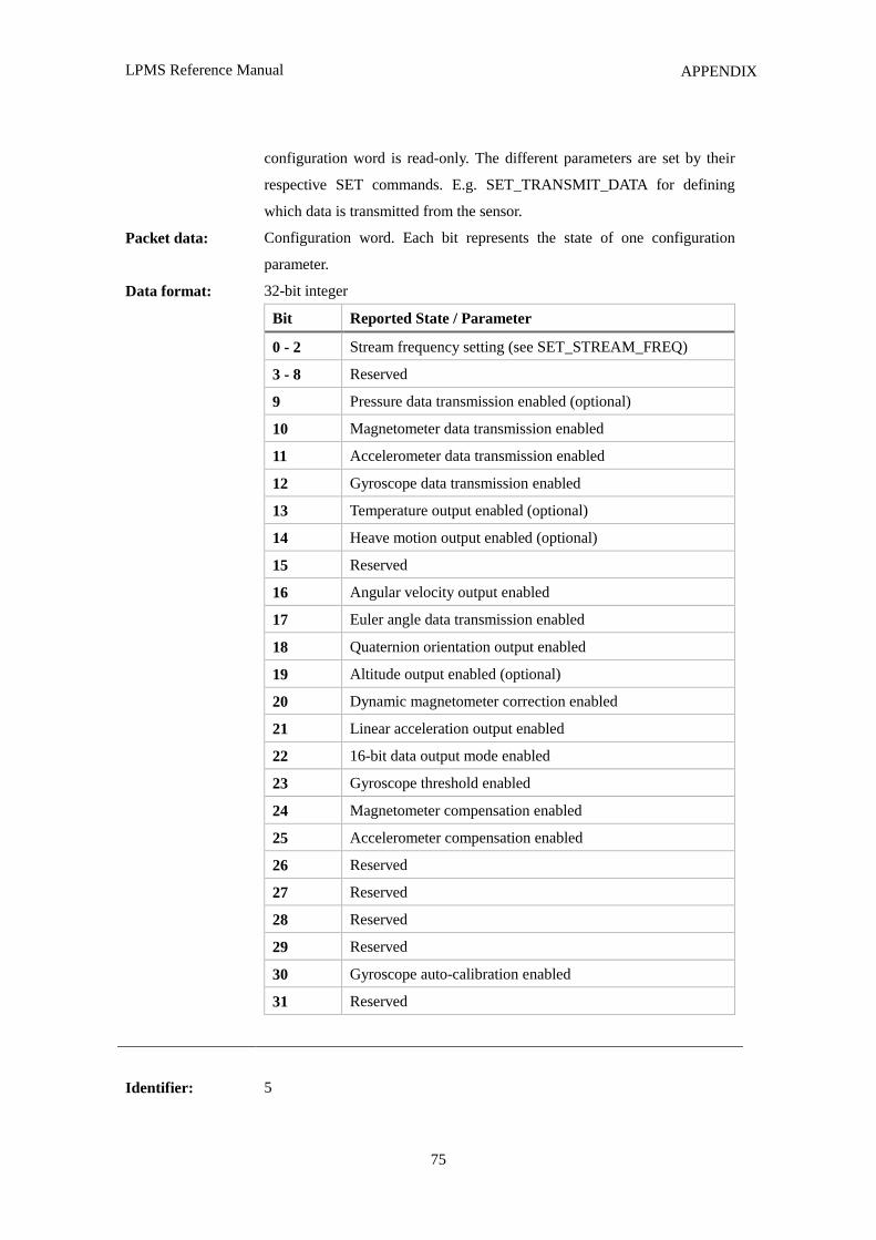
LPMS Reference Manual
75
APPENDIX
Packet data:
Data format:
configuration word is read-only. The different parameters are set by their
respective SET commands. E.g. SET_TRANSMIT_DATA for defining
which data is transmitted from the sensor.
Configuration word. Each bit represents the state of one configuration
parameter.
32-bit integer
Bit Reported State / Parameter
0 - 2 Stream frequency setting (see SET_STREAM_FREQ)
3 - 8 Reserved
9 Pressure data transmission enabled (optional)
10 Magnetometer data transmission enabled
11 Accelerometer data transmission enabled
12 Gyroscope data transmission enabled
13 Temperature output enabled (optional)
14 Heave motion output enabled (optional)
15 Reserved
16 Angular velocity output enabled
17 Euler angle data transmission enabled
18 Quaternion orientation output enabled
19 Altitude output enabled (optional)
20 Dynamic magnetometer correction enabled
21 Linear acceleration output enabled
22 16-bit data output mode enabled
23 Gyroscope threshold enabled
24 Magnetometer compensation enabled
25 Accelerometer compensation enabled
26 Reserved
27 Reserved
28 Reserved
29 Reserved
30 Gyroscope auto-calibration enabled
31 Reserved
Identifier:
5
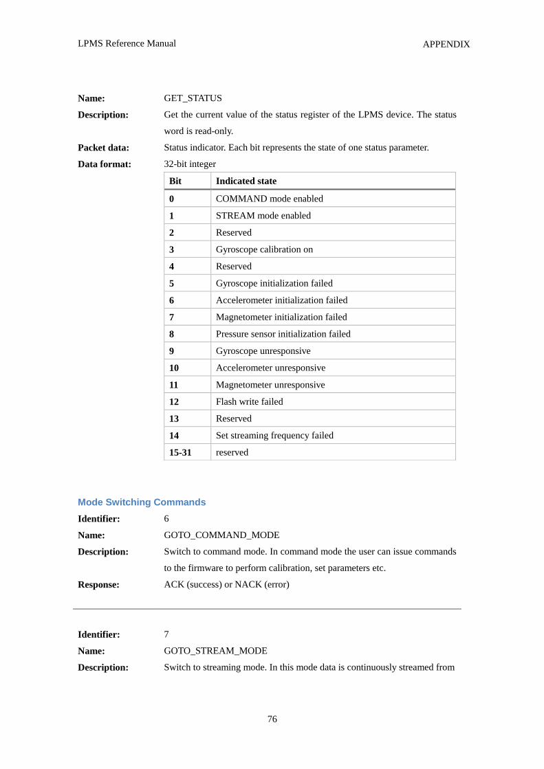
LPMS Reference Manual
76
APPENDIX
Name:
Description:
Packet data:
Data format:
GET_STATUS
Get the current value of the status register of the LPMS device. The status
word is read-only.
Status indicator. Each bit represents the state of one status parameter.
32-bit integer
Bit Indicated state
0 COMMAND mode enabled
1 STREAM mode enabled
2 Reserved
3 Gyroscope calibration on
4 Reserved
5 Gyroscope initialization failed
6 Accelerometer initialization failed
7 Magnetometer initialization failed
8 Pressure sensor initialization failed
9 Gyroscope unresponsive
10 Accelerometer unresponsive
11 Magnetometer unresponsive
12 Flash write failed
13 Reserved
14 Set streaming frequency failed
15-31 reserved
Mode Switching Commands
Identifier:
Name:
Description:
Response:
6
GOTO_COMMAND_MODE
Switch to command mode. In command mode the user can issue commands
to the firmware to perform calibration, set parameters etc.
ACK (success) or NACK (error)
Identifier:
Name:
Description:
7
GOTO_STREAM_MODE
Switch to streaming mode. In this mode data is continuously streamed from
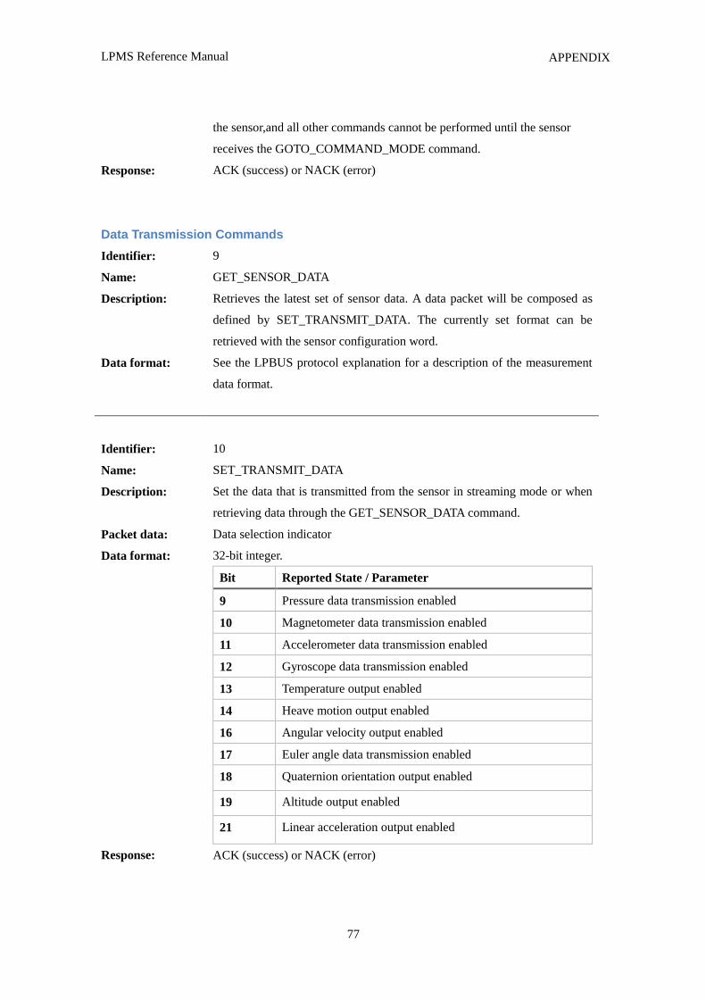
LPMS Reference Manual
77
APPENDIX
Response:
the sensor,and all other commands cannot be performed until the sensor
receives the GOTO_COMMAND_MODE command.
ACK (success) or NACK (error)
Data Transmission Commands
Identifier:
Name:
Description:
Data format:
9
GET_SENSOR_DATA
Retrieves the latest set of sensor data. A data packet will be composed as
defined by SET_TRANSMIT_DATA. The currently set format can be
retrieved with the sensor configuration word.
See the LPBUS protocol explanation for a description of the measurement
data format.
Identifier:
Name:
Description:
Packet data:
Data format:
Response:
10
SET_TRANSMIT_DATA
Set the data that is transmitted from the sensor in streaming mode or when
retrieving data through the GET_SENSOR_DATA command.
Data selection indicator
32-bit integer.
Bit Reported State / Parameter
9 Pressure data transmission enabled
10 Magnetometer data transmission enabled
11 Accelerometer data transmission enabled
12 Gyroscope data transmission enabled
13 Temperature output enabled
14 Heave motion output enabled
16 Angular velocity output enabled
17 Euler angle data transmission enabled
18 Quaternion orientation output enabled
19 Altitude output enabled
21 Linear acceleration output enabled
ACK (success) or NACK (error)
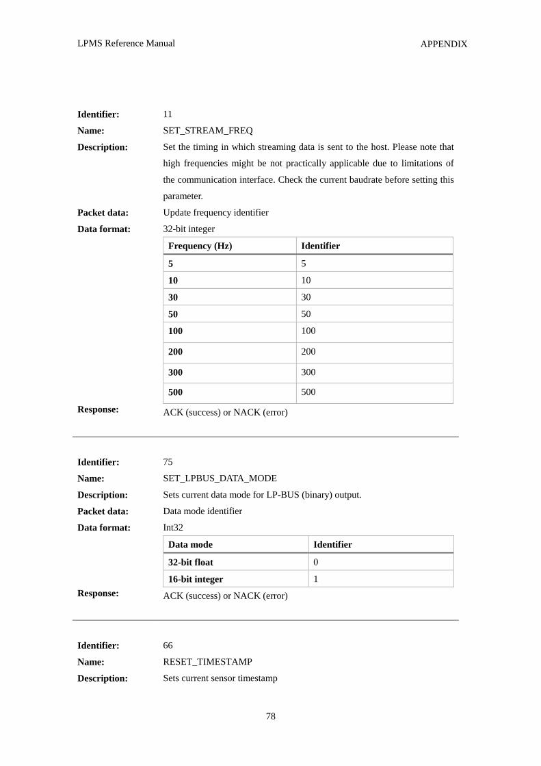
LPMS Reference Manual
78
APPENDIX
Identifier:
Name:
Description:
Packet data:
Data format:
Response:
11
SET_STREAM_FREQ
Set the timing in which streaming data is sent to the host. Please note that
high frequencies might be not practically applicable due to limitations of
the communication interface. Check the current baudrate before setting this
parameter.
Update frequency identifier
32-bit integer
Frequency (Hz) Identifier
5 5
10 10
30 30
50 50
100 100
200 200
300 300
500 500
ACK (success) or NACK (error)
Identifier:
Name:
Description:
Packet data:
Data format:
Response:
75
SET_LPBUS_DATA_MODE
Sets current data mode for LP-BUS (binary) output.
Data mode identifier
Int32
Data mode Identifier
32-bit float 0
16-bit integer 1
ACK (success) or NACK (error)
Identifier:
Name:
Description:
66
RESET_TIMESTAMP
Sets current sensor timestamp
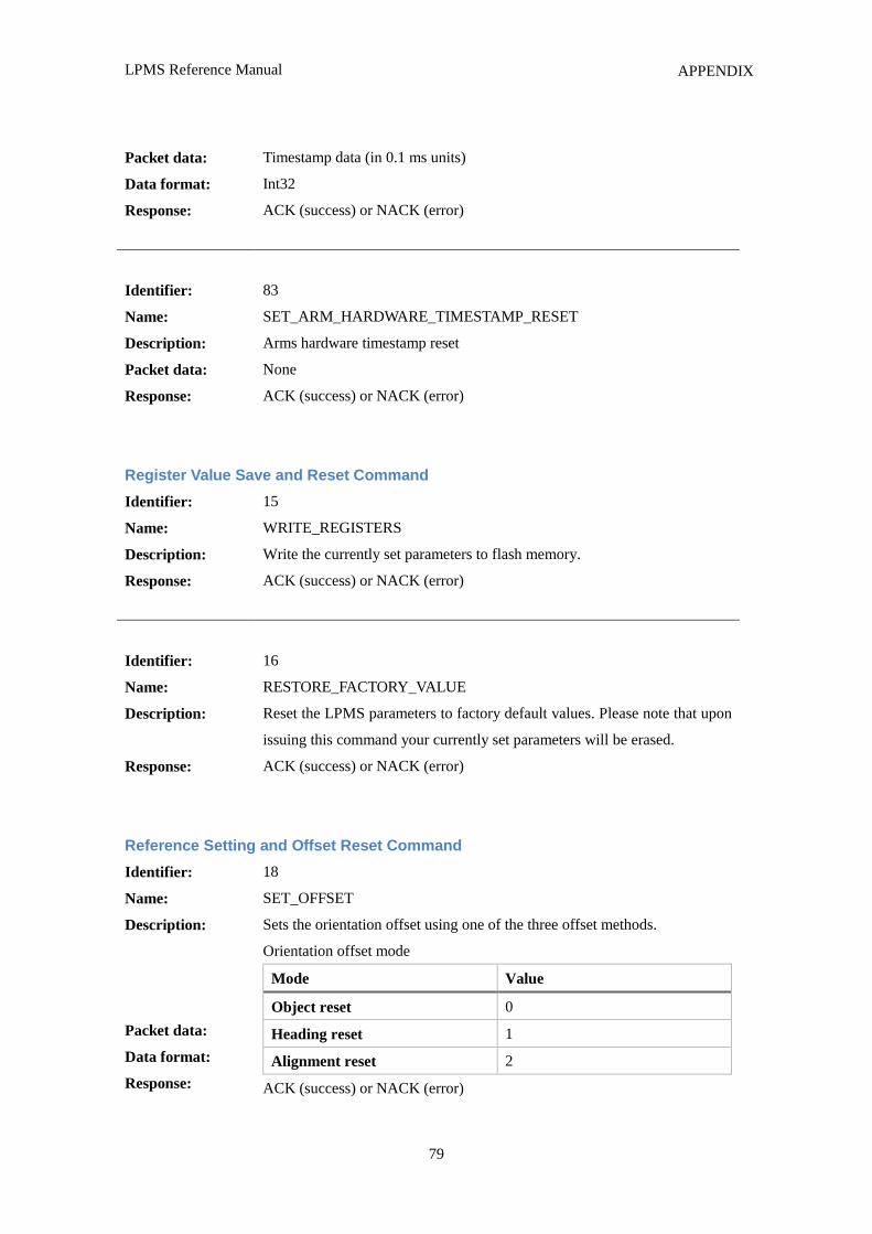
LPMS Reference Manual
79
APPENDIX
Packet data:
Data format:
Response:
Timestamp data (in 0.1 ms units)
Int32
ACK (success) or NACK (error)
Identifier:
Name:
Description:
Packet data:
Response:
83
SET_ARM_HARDWARE_TIMESTAMP_RESET
Arms hardware timestamp reset
None
ACK (success) or NACK (error)
Register Value Save and Reset Command
Identifier:
Name:
Description:
Response:
15
WRITE_REGISTERS
Write the currently set parameters to flash memory.
ACK (success) or NACK (error)
Identifier:
Name:
Description:
Response:
16
RESTORE_FACTORY_VALUE
Reset the LPMS parameters to factory default values. Please note that upon
issuing this command your currently set parameters will be erased.
ACK (success) or NACK (error)
Reference Setting and Offset Reset Command
Identifier:
Name:
Description:
Packet data:
Data format:
Response:
18
SET_OFFSET
Sets the orientation offset using one of the three offset methods.
Orientation offset mode
Mode Value
Object reset 0
Heading reset 1
Alignment reset 2
ACK (success) or NACK (error)
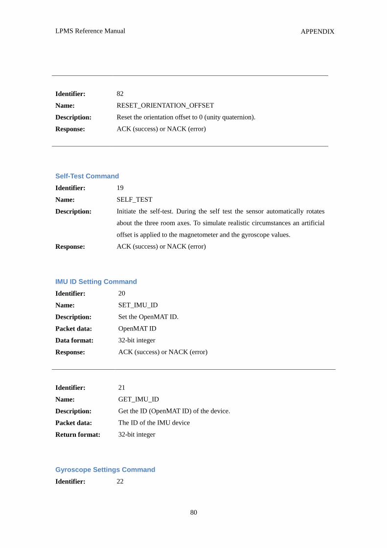
LPMS Reference Manual
80
APPENDIX
Identifier:
Name:
Description:
Response:
82
RESET_ORIENTATION_OFFSET
Reset the orientation offset to 0 (unity quaternion).
ACK (success) or NACK (error)
Self-Test Command
Identifier:
Name:
Description:
Response:
19
SELF_TEST
Initiate the self-test. During the self test the sensor automatically rotates
about the three room axes. To simulate realistic circumstances an artificial
offset is applied to the magnetometer and the gyroscope values.
ACK (success) or NACK (error)
IMU ID Setting Command
Identifier:
Name:
Description:
Packet data:
Data format:
Response:
20
SET_IMU_ID
Set the OpenMAT ID.
OpenMAT ID
32-bit integer
ACK (success) or NACK (error)
Identifier:
Name:
Description:
Packet data:
Return format:
21
GET_IMU_ID
Get the ID (OpenMAT ID) of the device.
The ID of the IMU device
32-bit integer
Gyroscope Settings Command
Identifier: 22
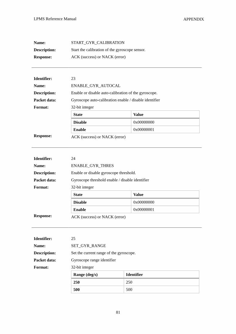
LPMS Reference Manual
81
APPENDIX
Name:
Description:
Response:
START_GYR_CALIBRATION
Start the calibration of the gyroscope sensor.
ACK (success) or NACK (error)
Identifier:
Name:
Description:
Packet data:
Format:
Response:
23
ENABLE_GYR_AUTOCAL
Enable or disable auto-calibration of the gyroscope.
Gyroscope auto-calibration enable / disable identifier
32-bit integer
State Value
Disable 0x00000000
Enable 0x00000001
ACK (success) or NACK (error)
Identifier:
Name:
Description:
Packet data:
Format:
Response:
24
ENABLE_GYR_THRES
Enable or disable gyroscope threshold.
Gyroscope threshold enable / disable identifier
32-bit integer
State Value
Disable 0x00000000
Enable 0x00000001
ACK (success) or NACK (error)
Identifier:
Name:
Description:
Packet data:
Format:
25
SET_GYR_RANGE
Set the current range of the gyroscope.
Gyroscope range identifier
32-bit integer
Range (deg/s) Identifier
250 250
500 500
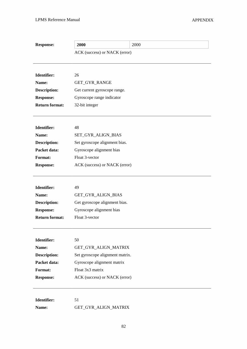
LPMS Reference Manual
82
APPENDIX
Response: 2000 2000
ACK (success) or NACK (error)
Identifier:
Name:
Description:
Response:
Return format:
26
GET_GYR_RANGE
Get current gyroscope range.
Gyroscope range indicator
32-bit integer
Identifier:
Name:
Description:
Packet data:
Format:
Response:
48
SET_GYR_ALIGN_BIAS
Set gyroscope alignment bias.
Gyroscope alignment bias
Float 3-vector
ACK (success) or NACK (error)
Identifier:
Name:
Description:
Response:
Return format:
49
GET_GYR_ALIGN_BIAS
Get gyroscope alignment bias.
Gyroscope alignment bias
Float 3-vector
Identifier:
Name:
Description:
Packet data:
Format:
Response:
50
GET_GYR_ALIGN_MATRIX
Set gyroscope alignment matrix.
Gyroscope alignment matrix
Float 3x3 matrix
ACK (success) or NACK (error)
Identifier:
Name:
51
GET_GYR_ALIGN_MATRIX
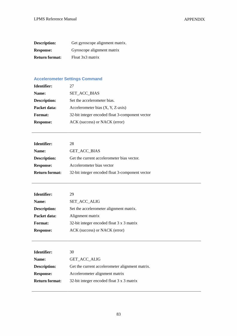
LPMS Reference Manual
83
APPENDIX
Description:
Response:
Return format:
Get gyroscope alignment matrix.
Gyroscope alignment matrix
Float 3x3 matrix
Accelerometer Settings Command
Identifier:
Name:
Description:
Packet data:
Format:
Response:
27
SET_ACC_BIAS
Set the accelerometer bias.
Accelerometer bias (X, Y, Z-axis)
32-bit integer encoded float 3-component vector
ACK (success) or NACK (error)
Identifier:
Name:
Description:
Response:
Return format:
28
GET_ACC_BIAS
Get the current accelerometer bias vector.
Accelerometer bias vector
32-bit integer encoded float 3-component vector
Identifier:
Name:
Description:
Packet data:
Format:
Response:
29
SET_ACC_ALIG
Set the accelerometer alignment matrix.
Alignment matrix
32-bit integer encoded float 3 x 3 matrix
ACK (success) or NACK (error)
Identifier:
Name:
Description:
Response:
Return format:
30
GET_ACC_ALIG
Get the current accelerometer alignment matrix.
Accelerometer alignment matrix
32-bit integer encoded float 3 x 3 matrix
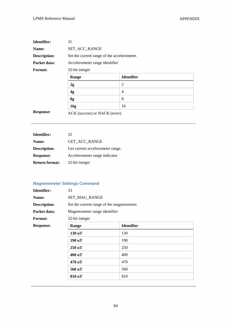
LPMS Reference Manual
84
APPENDIX
Identifier:
Name:
Description:
Packet data:
Format:
Response:
31
SET_ACC_RANGE
Set the current range of the accelerometer.
Accelerometer range identifier
32-bit integer
Range Identifier
2g 2
4g 4
8g 8
16g 16
ACK (success) or NACK (error)
Identifier:
Name:
Description:
Response:
Return format:
32
GET_ACC_RANGE
Get current accelerometer range.
Accelerometer range indicator
32-bit integer
Magnetometer Settings Command
Identifier:
Name:
Description:
Packet data:
Format:
Response:
33
SET_MAG_RANGE
Set the current range of the magnetometer.
Magnetometer range identifier
32-bit integer
Range Identifier
130 uT 130
190 uT 190
250 uT 250
400 uT 400
470 uT 470
560 uT 560
810 uT 810
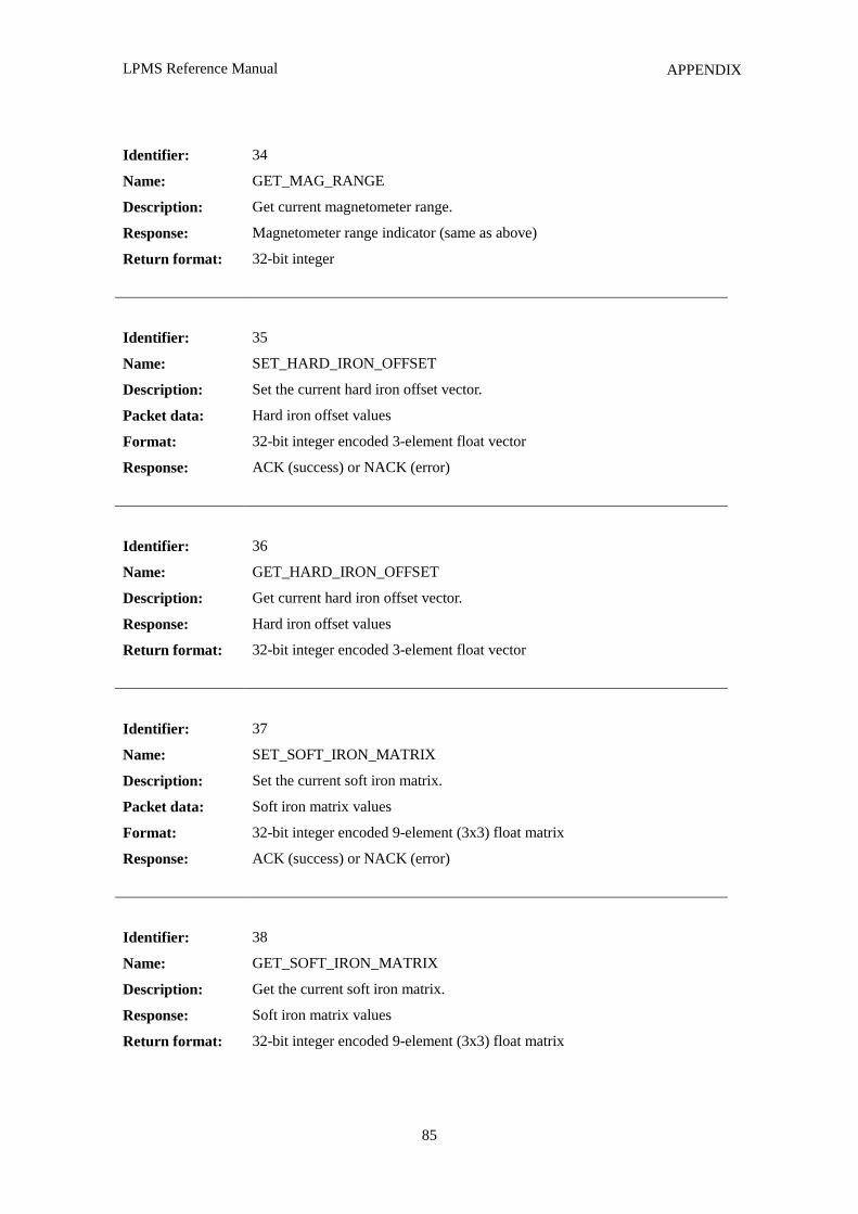
LPMS Reference Manual
85
APPENDIX
Identifier:
Name:
Description:
Response:
Return format:
34
GET_MAG_RANGE
Get current magnetometer range.
Magnetometer range indicator (same as above)
32-bit integer
Identifier:
Name:
Description:
Packet data:
Format:
Response:
35
SET_HARD_IRON_OFFSET
Set the current hard iron offset vector.
Hard iron offset values
32-bit integer encoded 3-element float vector
ACK (success) or NACK (error)
Identifier:
Name:
Description:
Response:
Return format:
36
GET_HARD_IRON_OFFSET
Get current hard iron offset vector.
Hard iron offset values
32-bit integer encoded 3-element float vector
Identifier:
Name:
Description:
Packet data:
Format:
Response:
37
SET_SOFT_IRON_MATRIX
Set the current soft iron matrix.
Soft iron matrix values
32-bit integer encoded 9-element (3x3) float matrix
ACK (success) or NACK (error)
Identifier:
Name:
Description:
Response:
Return format:
38
GET_SOFT_IRON_MATRIX
Get the current soft iron matrix.
Soft iron matrix values
32-bit integer encoded 9-element (3x3) float matrix
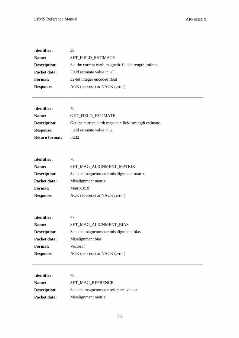
LPMS Reference Manual
86
APPENDIX
Identifier:
Name:
Description:
Packet data:
Format:
Response:
39
SET_FIELD_ESTIMATE
Set the current earth magnetic field strength estimate.
Field estimate value in uT
32-bit integer encoded float
ACK (success) or NACK (error)
Identifier:
Name:
Description:
Response:
Return format:
40
GET_FIELD_ESTIMATE
Get the current earth magnetic field strength estimate.
Field estimate value in uT
Int32
Identifier:
Name:
Description:
Packet data:
Format:
Response:
76
SET_MAG_ALIGNMENT_MATRIX
Sets the magnetometer misalignment matrix.
Misalignment matrix
Matrix3x3f
ACK (success) or NACK (error)
Identifier:
Name:
Description:
Packet data:
Format:
Response:
77
SET_MAG_ALIGNMENT_BIAS
Sets the magnetometer misalignment bias.
Misalignment bias
Vector3f
ACK (success) or NACK (error)
Identifier:
Name:
Description:
Packet data:
78
SET_MAG_REFRENCE
Sets the magnetometer reference vector.
Misalignment matrix
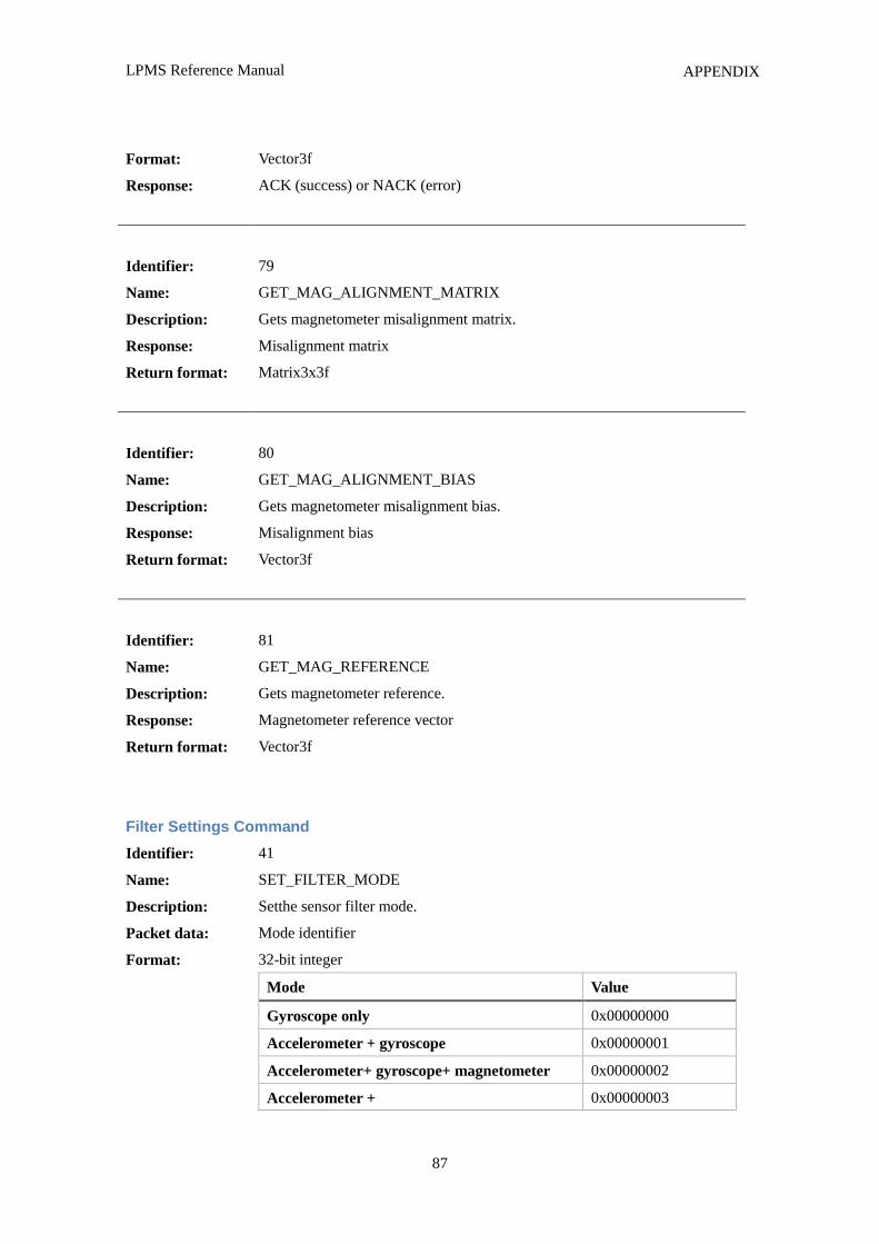
LPMS Reference Manual
87
APPENDIX
Format:
Response:
Vector3f
ACK (success) or NACK (error)
Identifier:
Name:
Description:
Response:
Return format:
79
GET_MAG_ALIGNMENT_MATRIX
Gets magnetometer misalignment matrix.
Misalignment matrix
Matrix3x3f
Identifier:
Name:
Description:
Response:
Return format:
80
GET_MAG_ALIGNMENT_BIAS
Gets magnetometer misalignment bias.
Misalignment bias
Vector3f
Identifier:
Name:
Description:
Response:
Return format:
81
GET_MAG_REFERENCE
Gets magnetometer reference.
Magnetometer reference vector
Vector3f
Filter Settings Command
Identifier:
Name:
Description:
Packet data:
Format:
41
SET_FILTER_MODE
Setthe sensor filter mode.
Mode identifier
32-bit integer
Mode Value
Gyroscope only 0x00000000
Accelerometer + gyroscope 0x00000001
Accelerometer+ gyroscope+ magnetometer 0x00000002
Accelerometer + 0x00000003
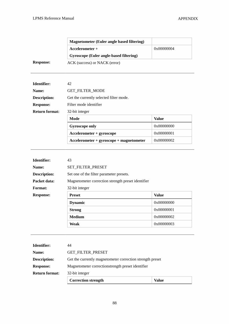
LPMS Reference Manual
88
APPENDIX
Response:
Magnetometer (Euler angle based filtering)
Accelerometer +
Gyroscope (Euler angle-based filtering)
0x00000004
ACK (success) or NACK (error)
Identifier:
Name:
Description:
Response:
Return format:
42
GET_FILTER_MODE
Get the currently selected filter mode.
Filter mode identifier
32-bit integer
Mode Value
Gyroscope only 0x00000000
Accelerometer + gyroscope 0x00000001
Accelerometer + gyroscope + magnetometer 0x00000002
Identifier:
Name:
Description:
Packet data:
Format:
Response:
43
SET_FILTER_PRESET
Set one of the filter parameter presets.
Magnetometer correction strength preset identifier
32-bit integer
Preset Value
Dynamic 0x00000000
Strong 0x00000001
Medium 0x00000002
Weak 0x00000003
Identifier:
Name:
Description:
Response:
Return format:
44
GET_FILTER_PRESET
Get the currently magnetometer correction strength preset
Magnetometer correctionstrength preset identifier
32-bit integer
Correction strength Value
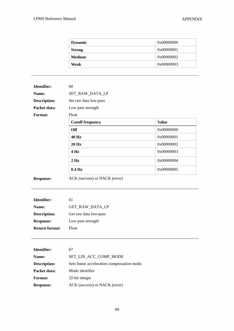
LPMS Reference Manual
89
APPENDIX
Dynamic 0x00000000
Strong 0x00000001
Medium 0x00000002
Weak 0x00000003
Identifier:
Name:
Description:
Packet data:
Format:
Response:
60
SET_RAW_DATA_LP
Set raw data low-pass
Low pass strength
Float
Cutoff frequency Value
Off 0x00000000
40 Hz 0x00000001
20 Hz 0x00000002
4 Hz 0x00000003
2 Hz 0x00000004
0.4 Hz 0x00000005
ACK (success) or NACK (error)
Identifier:
Name:
Description:
Response:
Return format:
61
GET_RAW_DATA_LP
Get raw data low-pass
Low pass strength
Float
Identifier:
Name:
Description:
Packet data:
Format:
Response:
67
SET_LIN_ACC_COMP_MODE
Sets linear acceleration compensation mode.
Mode identifier
32-bit integer
ACK (success) or NACK (error)
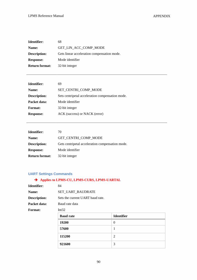
LPMS Reference Manual
90
APPENDIX
Identifier:
Name:
Description:
Response:
Return format:
68
GET_LIN_ACC_COMP_MODE
Gets linear acceleration compensation mode.
Mode identifier
32-bit integer
Identifier:
Name:
Description:
Packet data:
Format:
Response:
69
SET_CENTRI_COMP_MODE
Sets centripetal acceleration compensation mode.
Mode identifier
32-bit integer
ACK (success) or NACK (error)
Identifier:
Name:
Description:
Response:
Return format:
70
GET_CENTRI_COMP_MODE
Gets centripetal acceleration compensation mode.
Mode identifier
32-bit integer
UART Settings Commands
Applies to LPMS-CU, LPMS-CURS, LPMS-UARTAL
Identifier:
Name:
Description:
Packet data:
Format:
84
SET_UART_BAUDRATE
Sets the current UART baud rate.
Baud rate data
Int32
Baud rate Identifier
19200 0
57600 1
115200 2
921600 3
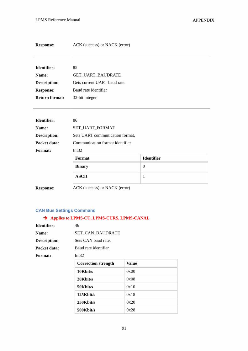
LPMS Reference Manual
91
APPENDIX
Response: ACK (success) or NACK (error)
Identifier:
Name:
Description:
Response:
Return format:
85
GET_UART_BAUDRATE
Gets current UART baud rate.
Baud rate identifier
32-bit integer
Identifier:
Name:
Description:
Packet data:
Format:
Response:
86
SET_UART_FORMAT
Sets UART communication format,
Communication format identifier
Int32
Format Identifier
Binary 0
ASCII 1
ACK (success) or NACK (error)
CAN Bus Settings Command
Applies to LPMS-CU, LPMS-CURS, LPMS-CANAL
Identifier:
Name:
Description:
Packet data:
Format:
46
SET_CAN_BAUDRATE
Sets CAN baud rate.
Baud rate identifier
Int32
Correction strength Value
10Kbit/s 0x00
20Kbit/s 0x08
50Kbit/s 0x10
125Kbit/s 0x18
250Kbit/s 0x20
500Kbit/s 0x28
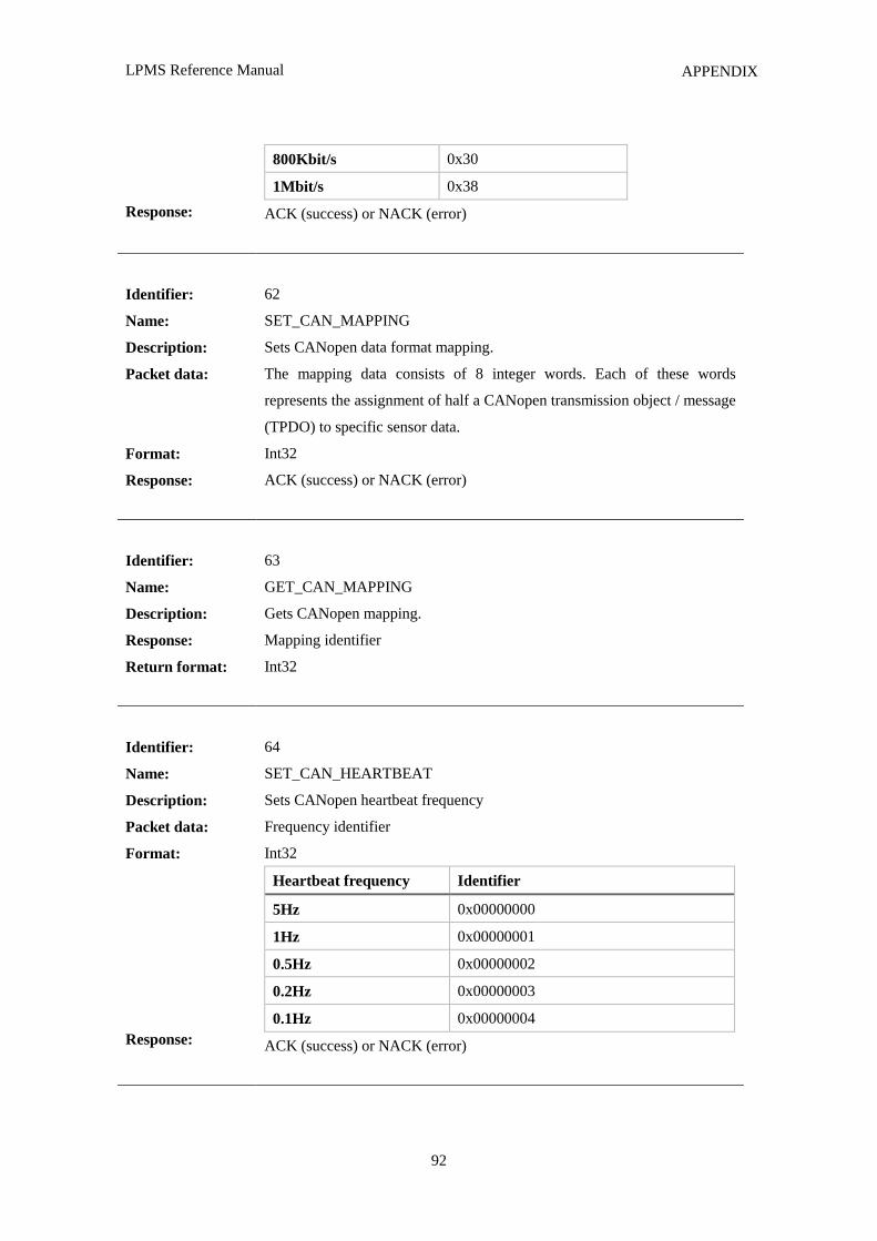
LPMS Reference Manual
92
APPENDIX
Response:
800Kbit/s 0x30
1Mbit/s 0x38
ACK (success) or NACK (error)
Identifier:
Name:
Description:
Packet data:
Format:
Response:
62
SET_CAN_MAPPING
Sets CANopen data format mapping.
The mapping data consists of 8 integer words. Each of these words
represents the assignment of half a CANopen transmission object / message
(TPDO) to specific sensor data.
Int32
ACK (success) or NACK (error)
Identifier:
Name:
Description:
Response:
Return format:
63
GET_CAN_MAPPING
Gets CANopen mapping.
Mapping identifier
Int32
Identifier:
Name:
Description:
Packet data:
Format:
Response:
64
SET_CAN_HEARTBEAT
Sets CANopen heartbeat frequency
Frequency identifier
Int32
Heartbeat frequency Identifier
5Hz 0x00000000
1Hz 0x00000001
0.5Hz 0x00000002
0.2Hz 0x00000003
0.1Hz 0x00000004
ACK (success) or NACK (error)
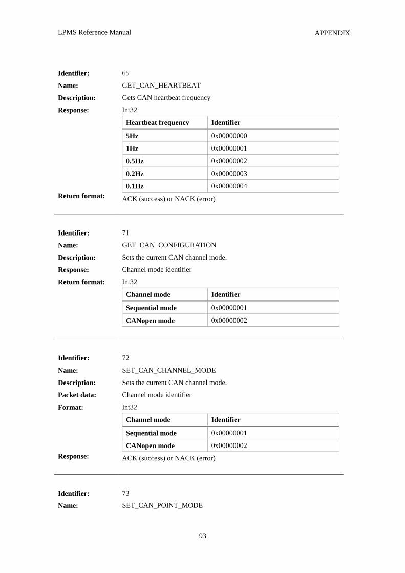
LPMS Reference Manual
93
APPENDIX
Identifier:
Name:
Description:
Response:
Return format:
65
GET_CAN_HEARTBEAT
Gets CAN heartbeat frequency
Int32
Heartbeat frequency Identifier
5Hz 0x00000000
1Hz 0x00000001
0.5Hz 0x00000002
0.2Hz 0x00000003
0.1Hz 0x00000004
ACK (success) or NACK (error)
Identifier:
Name:
Description:
Response:
Return format:
71
GET_CAN_CONFIGURATION
Sets the current CAN channel mode.
Channel mode identifier
Int32
Channel mode Identifier
Sequential mode 0x00000001
CANopen mode 0x00000002
Identifier:
Name:
Description:
Packet data:
Format:
Response:
72
SET_CAN_CHANNEL_MODE
Sets the current CAN channel mode.
Channel mode identifier
Int32
Channel mode Identifier
Sequential mode 0x00000001
CANopen mode 0x00000002
ACK (success) or NACK (error)
Identifier:
Name:
73
SET_CAN_POINT_MODE
LPMS Reference Manual
94
APPENDIX
Description:
Packet data:
Format:
Response:
Sets the current CAN point mode.
Point mode identifier
Int32
Channel mode Identifier
32-bit float mode 0x00000001
16-bit integer mode 0x00000002
ACK (success) or NACK (error)
Identifier:
Name:
Description:
Packet data:
Format:
Response:
74
SET_CAN_START_ID
Sets current CAN message start ID.
Start ID
Int32
ACK (success) or NACK (error)
LPMS Reference Manual
95
APPENDIX
APPENDIX C – SOFTWARE REVISION HISTORY
Version 1.3.3
SW: Added functionality to load 3D CAD data in OBJ format.
Version 1.3.2
FW: BUGFIX! Major overhaul of sensor timing.
FW: Speed optimization of sensor fusion algorithm.
Version 1.3.1
FW: Added ASCII CSV output option for UART models.
Version 1.3.0
FW / SW: Added hardware synchronization functionality.
FW / SW: Added selectable orientation offset modes (object, heading, alignment).
Version 1.2.9
SW: Moved ImuData.h from OpenMATCommon to LpSensor. OpenMATCommon has been
removed.
FW / SW: Switchable baud rate for UART communication. Default baud rate: 115200 bps.
FW / SW: Switchable baud rate for CAN bus communication. Default baud rate: 1 MBit/s.
Version 1.2.8
FW: BUGFIX! Newly added CAN channels now work correctly.
FW / SW: BUGFIX! Firmware upload with packet size 256 bytes now works. 128 byte for
LPMS-BLE.
Version 1.2.7
FW: BUGFIX! Removed timing overhead in I2C communication with gyroscope.
SW: BUGFIX! Display update when switching sensors in LpmsControl now correct.
Version 1.2.6
SW: Added Magnetometer misalignment calibration algorithm. Calibration can either be done by
comparison with acc / gyr data or using a Helmholtz coil.
SW: Added support for multiple BLE sensors.
FW: Added working firmware for BLE communication. Maximum transmission frequency is 30Hz.
LPMS Reference Manual
96
APPENDIX
Version 1.2.5
FW: Added possibility 16-bit data transfer mode for LPBUS.
SW: Added C3D file parser to LpMocap.
SW: Added AVI export functionality to LpMocap.
Version 1.2.4
SW: LpmsControl now uses QT5.
SW: LpSensor now uses C++11 for threading and therefore requires VS2012 on Windows.
SW: Updated LpMocap to support new direct network communication with LpmsControl.
SW: OpenMAT server has been deprecated.
Version 1.2.3
SW: BUGFIX! Quaternion data is now written in correct order into data file recorded by
LpmsControl.
FW: Added additional acceleration compensation setting (ultra) for very strong concussions.
FW / SW: Doubled the number of available channels for CAN bus assignment (8 -> 16).
Version 1.2.2
SW: Added 3D visualization and graphs to LPMS Android application.
FW: BUGFIX! In LPMS-CURS TTL version sensor didn‟t switch into TTL mode on first input byte
through TTL UART port.
SW: Further improvements to Android application.
Version 1.2.1
SW: Added replay functionality to LpmsControl.
SW: Added support for LPMS-CURS and LPMS-UARTAL.
FW: Adapted firmware for new LPMS-CURS.
Version 1.2.1
SW: Added support for IXXAT CAN bus interface.
FW / SW: Preliminary version of LPMS-BLE firmware and software.
SW: Removed 3rd
party libraries from project.
SW: Tested compatibility with Ubuntu Linux.
SW: BUGFIX! Fixed data overflow when connecting to LPMS-B.
Version 1.2.0
LPMS Reference Manual
97
APPENDIX
FW / SW: More effective queuing of output data via Bluetooth to guarantee correct transmission.
FW / SW: LpCAN protocol was modified to enhance performance for more than one LPMS-CU on
the same CAN bus. This change doesn‟t affect CANOpen or sequential CAN streaming.
SW: In case a transmission timeout occurs LpSensor now tries to re-connect for 5 times until it
reports a transmission error.
SW: Created a C wrapper of LpSensor for use of the library with C# and Matlab.
FW: Adjusted for stronger magnetometer compensation
Version 1.1.1
SW: Improved Bluetooth device discovery
SW: Implemented checks for invalid firmware file upload
FW: BUGFIX! Fixed bug in sequential CAN bus communication.
SW: Added timestamp parsing in Android application
SW: Basic support for multiple sensors in Android application
FW / SW: Added new options to CAN bus interface (Channel mode, Value mode, Start ID). 16-bit
fixed point values support.
FW / SW: Added possibility to synchronously reset timestamps for all connected sensors.
SW: BUGFIX! Fixed bug in detection of heave motion enabled sensor.
SW: Network support in OpenMAT (through ICE) has been removed for binary distributions. To
build an OpenMAT network OpenMAT needs to be built from source with ICE support
enabled. ICE is published under the GNU General Public License.
Version 1.1.0
SW: Added several parameter combos.
SW: Improved magnetometer calibration.
SW: Changed gyroscope calibration to use rate table.
FW: Added optional dynamic covariance adjustment for linear acceleration.
FW: Added optional dynamic covariance adjustment for rotational acceleration.
FW: Added timestamp to sensor data
FW: Added optional heave motion tracking
Version 1.0.15
SW: Moved data recording function into the library. Now managed from LpmsSensorManager.
Accurate timestamp synchronization.
SW: Added barometric pressure, altimeter, temperature display.
FW: Added CAN bus protocol with fixed-point values (Custom 3).
LPMS Reference Manual
98
APPENDIX
FW: Added gyroscope calibration.
FW: Added barometric pressure, altimeter, temperature output.
Version 1.0.14
FW: Finally fixed bug that had sensor communication freeze for several seconds in some cases.
FW: Added watchdog for gyro., acc. and mag. sensor. Reboot is data acquisition hangs. Good
for CAN bus critical applications.
SW: Complete configuration data write and read with each parameter change.
SW: Simplified interface a bit more.
Version 1.0.13
SW: Added icons instead of text button (toolbar).
SW: Added preferred devices dialog. Devices can be added and saved. Scan with every program start
not necessary.
SW: Calibration data can be saved to an XML file. Therefore data can be backed up and restored
before / after firmware update.
Version 1.0.12
SW: Magnetometer calibration calculation moved to LpmsControl to save resources.
SW: Added accelerometer misalignment calibration.
SW: Added selection of transmission data.
FW: Removed magnetometer calibration from firmware.
FW: Added custom 1 (formerly Aerospace CAN) and custom 2 CAN protocol.
Version 1.0.11
SW: Timeout for ACK and DATA was added for safety because of glitch in firmware.
SW: Linear acceleration indicator was added.
SW: Zeroing of initial IMU data was moved to LpmsSensorIo.
SW: Timeout and automatic reconnect (once) in case of connection loss.
FW: Reduced number of variables passed to filter.
FW: Added linear acceleration processing.
FW: Readjusted filter parameters (especially set mag. medium and low covariance higher). Good
setting especially for medium.
Version 1.0.10
SW: Added dip angle as indicator for field noise.
LPMS Reference Manual
99
APPENDIX
SW: Added covariance adjustment for removal of linear acceleration.
SW: Gradual covariance adjustment instead of switching.
FW: Online gyroscope bias can be switched off.
FW: Factory defaults reset implemented.
Version 1.0.8
SW: Added reset to factory defaults option.
SW: Implemented different sampling rates for data recording.
SW: Added field map window to display magnetic field calibration data.
SW: Added magnetic field noise indicator.
Version 1.0.9
FW: Online gyroscope bias compensation added.
FW: Dynamic magnetometer covariance adjustment implemented.
FW: Magnetic field map read-out to host is possible.
FW: Implementation of streaming mode.
Version 1.0.7
SW: Improved Bluetooth auto-discovery.
SW: Changed “parameter set” parameter to “magnetometer correction” with “strong”, “medium”
and “weak”.
Version 1.0.6
FW: Euler angles in radians are converted to degree in LpmsControl.
Version 1.0.5
SW: Adaption of GUI to new calibration routines.
SW: Added auto-calibration of magnetometer option to sensor settings.
SW: FTDI driver installation is now packaged with main installer again.
Version 1.0.4
SW: Improvement of automatic device detection routines.
SW: Centralized processing of CAN hardware I/O in CanEngine class.
SW: Interface classes for LpSensor and LpSensorManager to reduce dependencies.
Version 1.0.3
LPMS Reference Manual
100
APPENDIX
SW: Added debug and release 32-bit DLL and LIB files for the sensor data acquisition routines.
Packaged classes are: SensorManager, LpmsSensor (inherits LpSensor), ImuData, CalibrationData.
SW: LpmsControl from now on uses the LpSensor library and does not build the classes by itself.
Removed the corresponding content from CMakeLists.txt
Version 1.0.3
FW: Synchronization of UART write during SPI communication in the firmware.
SW: Re-built OpenMAT to be on the safe side that everything works.
Version 1.0.2
SW: BUGFIX! Fixed very fatal dependency bug (partially depending on debug DLLs)
Version 1.0.1
SW: Automatic device discovery was added.
SW: Progress bar for device discovery was added.
Version 1.0.0
SW / FW: First release based on a series of previous in-official releases.
SW: Support for WB-4 devices has been phased out.
SW: Full support for all LPMS models (CAN, USB and Bluetooth).
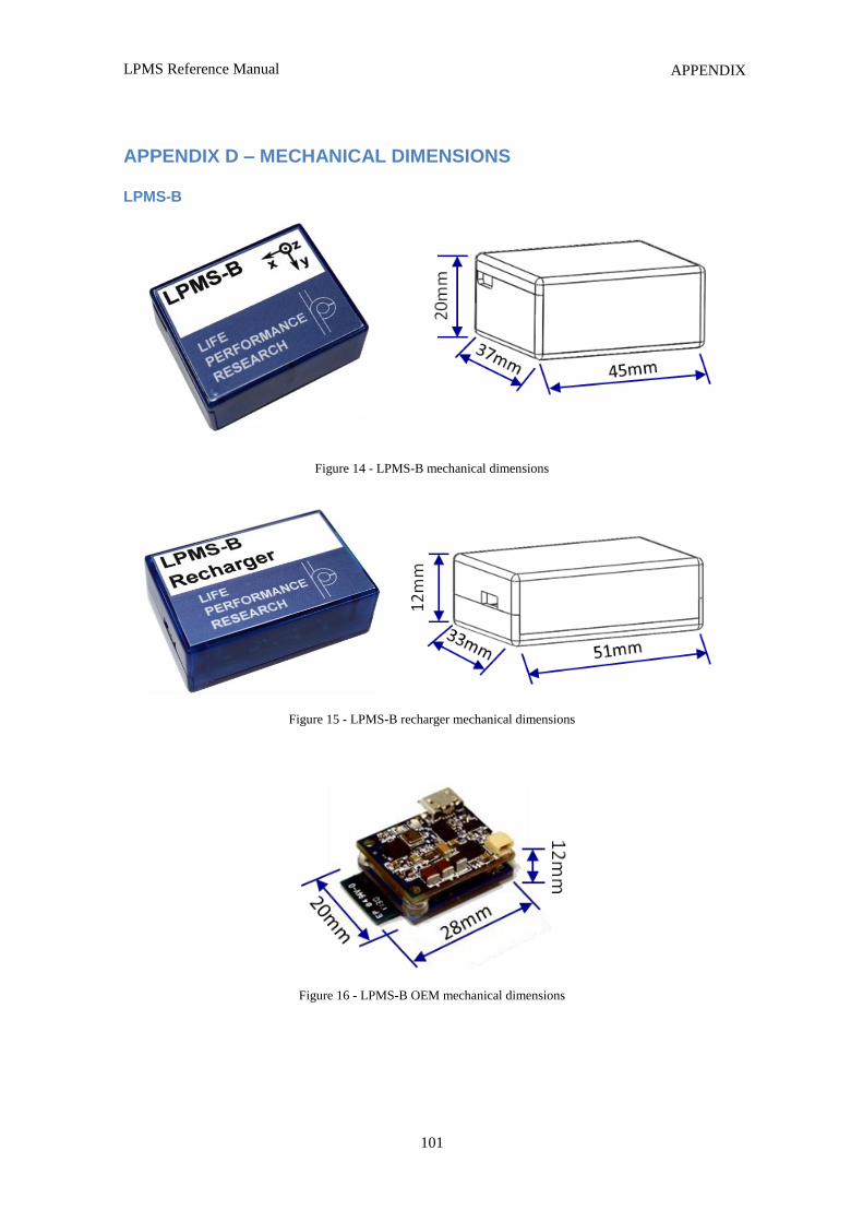
LPMS Reference Manual
101
APPENDIX
APPENDIX D – MECHANICAL DIMENSIONS
LPMS-B
Figure 15 - LPMS-B recharger mechanical dimensions
Figure 16 - LPMS-B OEM mechanical dimensions
Figure 14 - LPMS-B mechanical dimensions
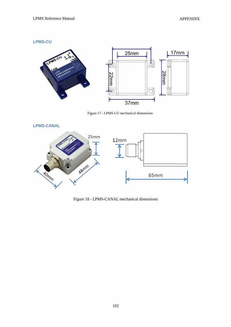
LPMS Reference Manual
102
APPENDIX
LPMS-CU
LPMS-CANAL
Figure 18 - LPMS-CANAL mechanical dimensions
Figure 17 - LPMS-CU mechanical dimensions
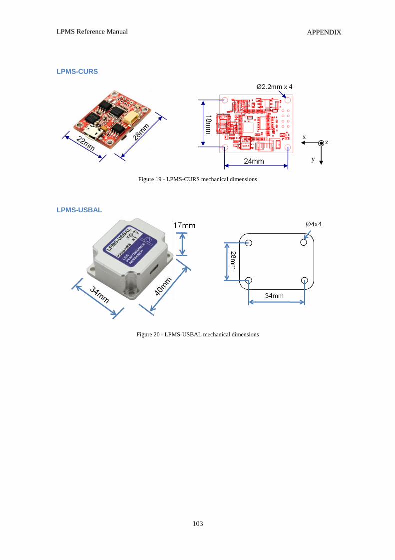
LPMS Reference Manual
103
APPENDIX
LPMS-CURS
Figure 19 - LPMS-CURS mechanical dimensions
LPMS-USBAL
Figure 20 - LPMS-USBAL mechanical dimensions
x
y
z
LPMS Reference Manual
104
APPENDIX
Please Read Carefully:
Information in this document is provided solely in connection with LP-RESEARCH products.
LP-RESEARCH reserves the right to make changes, corrections, modifications or improvements, to
this document, and the products and services described herein at any time, without notice.
All LP-RESEARCH products are sold pursuant to LP-RESEARCH‟s terms and conditions of sale.
Purchasers are solely responsible for the choice, selection and use of the LP-RESEARCH products
and services described herein, and LP-RESEARCH assumes no liability whatsoever relating to the
choice, selection or use of the LP-RESEARCH products and services described herein.
UNLESS OTHERWISE SET FORTH IN LP-RESEARCH’S TERMS AND CONDITIONS OF
SALE LP-RESEARCH DISCLAIMS ANY EXPRESS OR IMPLIED WARRANTY WITH
RESPECT TO THE USE AND/OR SALE OF LP-RESEARCH PRODUCTS INCLUDING
WITHOUT LIMITATION IMPLIED WARRANTIES OF MERCHANTABILITY, FITNESS
FOR A PARTICULAR PURPOSE (AND THEIR EQUIVALENTS UNDER THE LAWS OF
ANY JURISDICTION), OR INFRINGEMENT OF ANY PATENT, COPYRIGHT OR OTHER
INTELLECTUAL PROPERTY RIGHT.
LP-RESEARCH PRODUCTS ARE NOT RECOMMENDED, AUTHORIZED OR
WARRANTED FOR USE IN MILITARY, AIR CRAFT, SPACE, LIFE SAVING, OR LIFE
SUSTAINING APPLICATIONS, NOR IN PRODUCTS OR SYSTEMS WHERE FAILURE
OR MALFUNCTION MAY RESULT IN PERSONAL INJURY, DEATH, OR SEVERE
PROPERTY OR ENVIRONMENTAL DAMAGE. LP-RESEARCH PRODUCTS WHICH
ARE NOT SPECIFIED AS "AUTOMOTIVE GRADE" MAY ONLY BE USED IN
AUTOMOTIVE APPLICATIONS AT USER’S OWN RISK.
© 2014LP-RESEARCH - All rights reserved
Tokyo – Guangzhou – Munich
www.lp-research.com


![Curs 1-6 Traumatisme Curs [Compatibility Mode]](https://img.pdfslide.us/doc/110x75/577cdf6d1a28ab9e78b135f9/curs-1-6-traumatisme-curs-compatibility-mode.jpg)