Embed Size (px)
Citation preview

LPMS-ME1 DK
Manual Ver.1.4
LP-RESEARCH Inc.
http://www.lp-research.com

LPMS-ME1 DK Manual Ver. 1.4
- 1 -
Table of Contents
1. Document Revision History ............................................................................................... - 2 -
2. Introduction ........................................................................................................................ - 3 -
3. Operation ........................................................................................................................... - 4 -
3.1 Base Board Overview .............................................................................................. - 4 -
3.2 GUI Software ........................................................................................................... - 5 -
3.2.1 Software Installation ..................................................................................... - 5 -
3.2.2 Connection with PC ...................................................................................... - 7 -
3.2.3 Coordinate ................................................................................................... - 11 -
4. Hardware Functionality ................................................................................................... - 12 -
4.1 Hardware Structure ................................................................................................ - 12 -
4.2 Interfaces and Switches.......................................................................................... - 13 -
4.2.1 20-pins Header Connector .......................................................................... - 13 -
4.2.2 Setting Switches .......................................................................................... - 15 -
4.3 Schematics ............................................................................................................. - 16 -
4.4 Dimension .............................................................................................................. - 18 -
4.5 Operation Condition .............................................................................................. - 19 -
LPMS-ME1 DK Manual Ver. 1.4
- 2 -
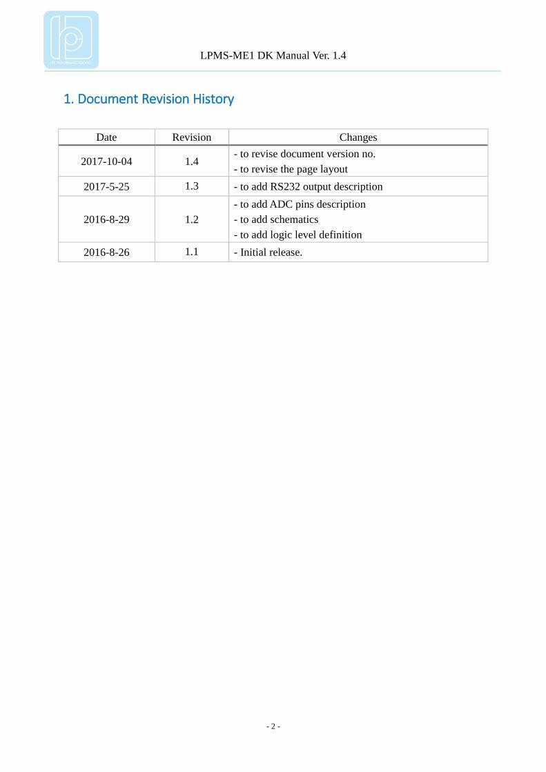
1. Document Revision History
Date Revision Changes
2017-10-04 1.4 - to revise document version no.
- to revise the page layout
2017-5-25 1.3 - to add RS232 output description
2016-8-29 1.2
- to add ADC pins description
- to add schematics
- to add logic level definition
2016-8-26 1.1 - Initial release.

LPMS-ME1 DK Manual Ver. 1.4
- 3 -
2. Introduction
LPMS-ME1 Development Kit (DK) contains a LPMS-ME1 sensor, a base board and
GUI software for sensor manipulation. The base board is designed for hosting LPMS-ME1
sensor, and multiple communication interfaces are available on the base board, such as USB,
UART and RS232. A 20-pins header connector is used for accessing all signals of LPMS-ME1.
The GUI software LpmsControl can visualize/save sensor data, and change the sensor
parameters.
Main features:
LPMS-ME1 DK base board
interface:USB, UART, RS232 (optional), I2C
status LED
setting switches, including settings of start mode, and data output interfaces
20-pins header to layout all LPMS-ME1 signals
LpmsControl software
sensor parameter setting
sensor calibration
7 types of data output
3D data visualization
data saving and replay
NOTE: RS232 interface is not available in default, please contact us if you need RS232
functionality.
LPMS-ME1 DK Manual Ver. 1.4
- 4 -
3. Operation
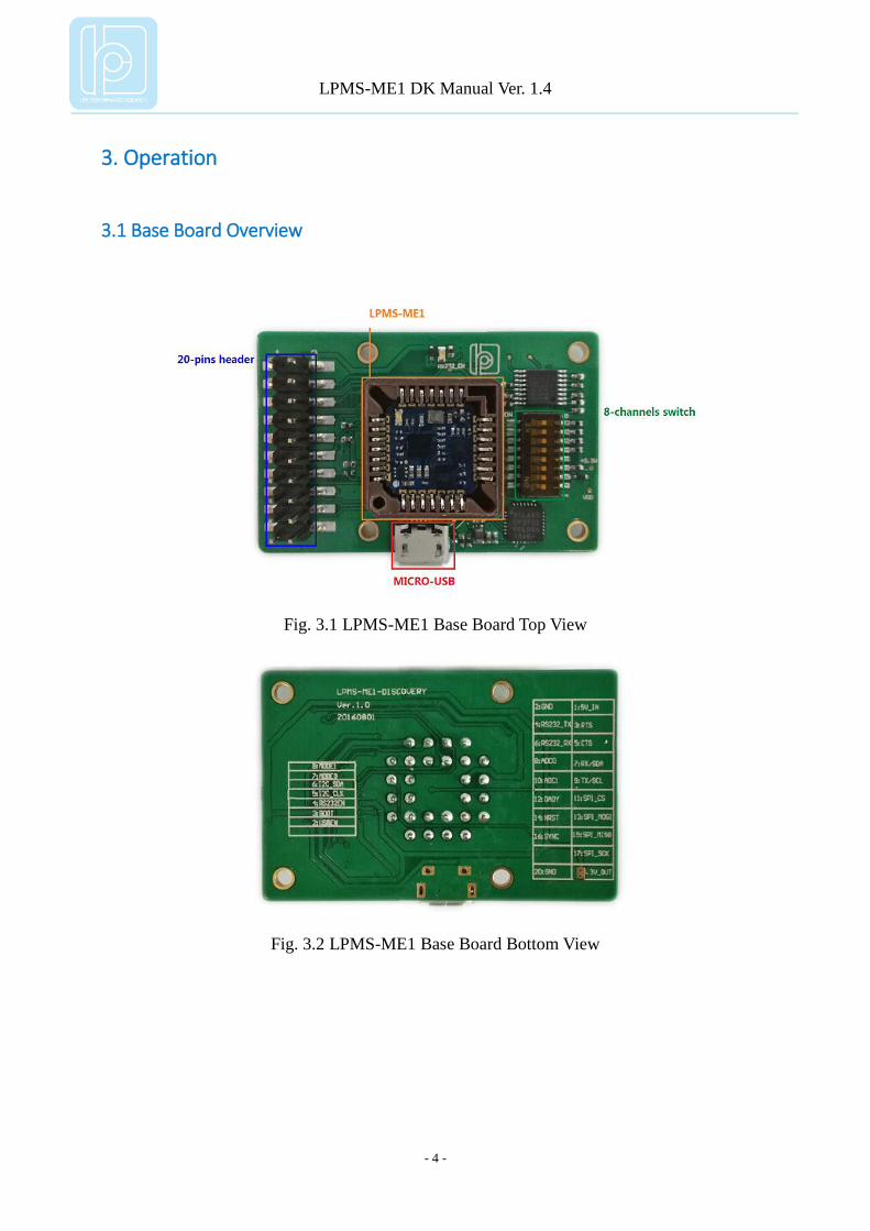
3.1 Base Board Overview
Fig. 3.1 LPMS-ME1 Base Board Top View
Fig. 3.2 LPMS-ME1 Base Board Bottom View
LPMS-ME1 DK Manual Ver. 1.4
- 5 -
3.2 GUI Software
3.2.1 Software Installation
We offer windows OS based software called LpmsControl for users to easily manipulate
the sensor. The LpmsControl software is a sub program of OpenMAT software. Please choose
a correct version of OpenMAT software from our homepage based on the operation system
specification. The followings show an example of installing the OpenMAT software under
Windows 7 32bit system.
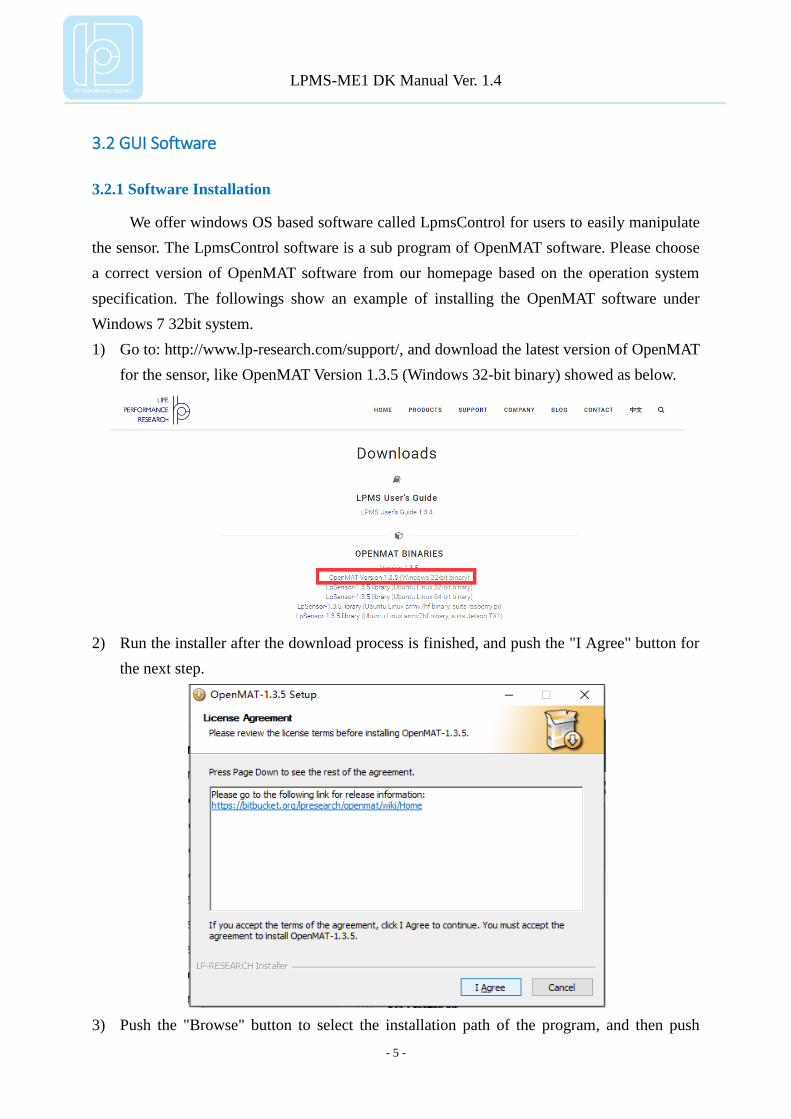
1) Go to: http://www.lp-research.com/support/, and download the latest version of OpenMAT
for the sensor, like OpenMAT Version 1.3.5 (Windows 32-bit binary) showed as below.
2) Run the installer after the download process is finished, and push the "I Agree" button for
the next step.
3) Push the "Browse" button to select the installation path of the program, and then push

LPMS-ME1 DK Manual Ver. 1.4
- 6 -
"Install" to start the installation process.
4) Push the "Close" button to complete the installation.
To run the LpmsControl software from the start menu of your windows system, you can
see the following interface.

LPMS-ME1 DK Manual Ver. 1.4
- 7 -
3.2.2 Connection with PC
In order to use USB,UART or RS232 connection, LPMS-ME1 must be set to UART
mode, and the corresponding hardware interface selection on base board must be enabled. The
interface selection information is introduced in the following sections in details.
Only an example of USB connection is illustrated here, but UART and RS232
connections have similar process.
After connecting the kit with a PC via USB port, the LED on base board should light on
and the LED on LPMS-ME1 should behave like a pulsating light at blue color, which indicates
the sensor is functionally working. Windows operation system will activate the installation of
USB drivers automatically, and the USB is configured as COM port like the image below.
Please follow the instructions below to complete the remaining steps.
1) To select the "Add/remove sensor" under "Connect" menu or click the "+" button on
toolbar.

LPMS-ME1 DK Manual Ver. 1.4
- 8 -
The "add device" window will pop out, as following.
2) To check the option of "Scan system serial ports (only for LPMS-UART)" and click the
"Scan devices" button to start the device discovery process. Please wait until the process is
finished.
3) To select the target sensor ID from the "Discovered devices" list, for example,
"LPMS-CUR(Port:COM9)" in the following image. This COM port should be same as the
one showed in the device manager of Windows.
4) To add the selected sensor to "Preferred devices" list by clicking the "Add device" button.
5) To click the "Save devices" button to save the preferred devices list, and return to main
interface of LpmsControl.

LPMS-ME1 DK Manual Ver. 1.4
- 9 -
6) To select the target sensor ID from the Preferred devices list, and click Connect function
under "Connect" menu or click the lightning button on toolbar to connect the sensor. Note:
The default baudrate of communication is 115200bps.
After completing all the steps above, the LPMS-ME1 should have been connecting with
windows system. Users can check all the data visualization and parameter settings of the
sensor from LpmsControl.
On the left side of the main interface of LpmsControl, users can change the sensor
settings, like measurement range, filter modes, data updating rate, etc. Moreover, the types of
output data can be modified by checking or unchecking the check box of each parameter. For
example, in the following image the "raw magnetometer" is checked so that the acquisition of
magnetic data is enabled.

LPMS-ME1 DK Manual Ver. 1.4
- 10 -

LPMS-ME1 DK Manual Ver. 1.4
- 11 -
3.2.3 Coordinate
Fig. 3.3 Development Kit Coordinate

LPMS-ME1 DK Manual Ver. 1.4
- 12 -
4. Hardware Functionality
4.1 Hardware Structure
Fig. 4.1 Development Kit Hardware Structure

LPMS-ME1 DK Manual Ver. 1.4
- 13 -
4.2 Interfaces and Switches
LPMS-ME1 DK contains one USB port, a 20-pins header connector (pitch 2.54mm), and
8 switches. The USB port can be connected to a host system for data transfer.
4.2.1 20-pins Header Connector
Table 4-1 20-pins Header Connector Pinout
No. Name No. Name
1 5V_IN 2 GND
3 RTS 4 RS232_TX
5 CTS 6 RS232_RX
7 RX/SDA 8 ADC0
9 TX/SCL 10 ADC1
11 SPI_CS 12 DADY
13 SPI_MOSI 14 NRST
15 SPI_MISO 16 SYNC
17 SPI_SCK 18 -
19 3.3V_OUT 20 GND
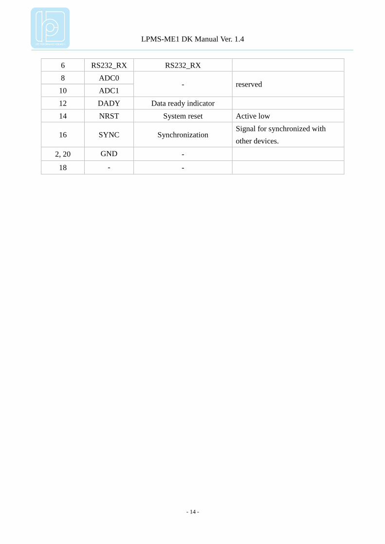
Table 4-2 Pinout Description of 20-pins Header Connector
No. Name Description Remark
1 5V_IN Power supply Power input (3.3V~5.5V)
3 RTS UART_RTS
5 CTS UART_CTS
7 RX/SDA UART mode UART_RX
I2C mode I
2C_SDA
9 TX/SCL UART mode UART_TX
I2C mode I
2C_SCL
11 SPI_CS Chip select
13 SPI_MOSI Slave Data Input
15 SPI_MISO Slave Data Output
17 SPI_SCK Serial Clock
19 3.3V_OUT - +3.3V voltage output
4 RS232_TX RS232_TX
LPMS-ME1 DK Manual Ver. 1.4
- 14 -
6 RS232_RX RS232_RX
8 ADC0 - reserved
10 ADC1
12 DADY Data ready indicator
14 NRST System reset Active low
16 SYNC Synchronization Signal for synchronized with
other devices.
2, 20 GND -
18 - -

LPMS-ME1 DK Manual Ver. 1.4
- 15 -
4.2.2 Setting Switches
Table 4-3 Description of Switches
No. Name Description
1 - -
2 USBEN On: enable USB port, Off: disable USB port.
Default: USB enabled.
3 BOOT
Boot pin of LPMS-ME1.
On: logic high, Off: logic low.
Default: Off.
4 RS232EN On: enable RS232 connection, Off: disable RS232 connection.
Default: RS232 disabled.
5 I2C_CLK
On: I2C CLK pulled high via 10K ohm resistor.
Off: I2C CLK no pull up.
Default: Off
6 I2C_SDA
On: I2C SDA pulled high via 10K ohm resistor.
Off: I2C SDA no pull up.
Default: Off
7 MODE0 On: logic low, Off: logic high
Default: On
8 MODE1 On: logic low, Off: logic high
Default: On
NOTE:
1. MODE0 and MODE1 are the communication mode selection pins of LPMS-ME1.
2. In order to use USB or RS232 connection, LPMS-ME1 must be set to operate in UART
mode, which means that MODE0 and MODE1 should be set to logic low.

LPMS-ME1 DK Manual Ver. 1.4
- 16 -
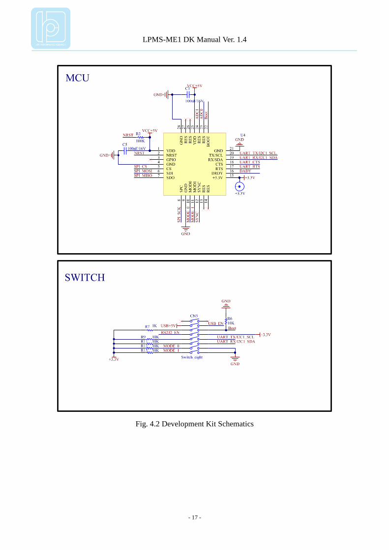
4.3 Schematics
LPMS-ME1 DK Manual Ver. 1.4
- 17 -
Fig. 4.2 Development Kit Schematics
LPMS-ME1 DK Manual Ver. 1.4
- 18 -
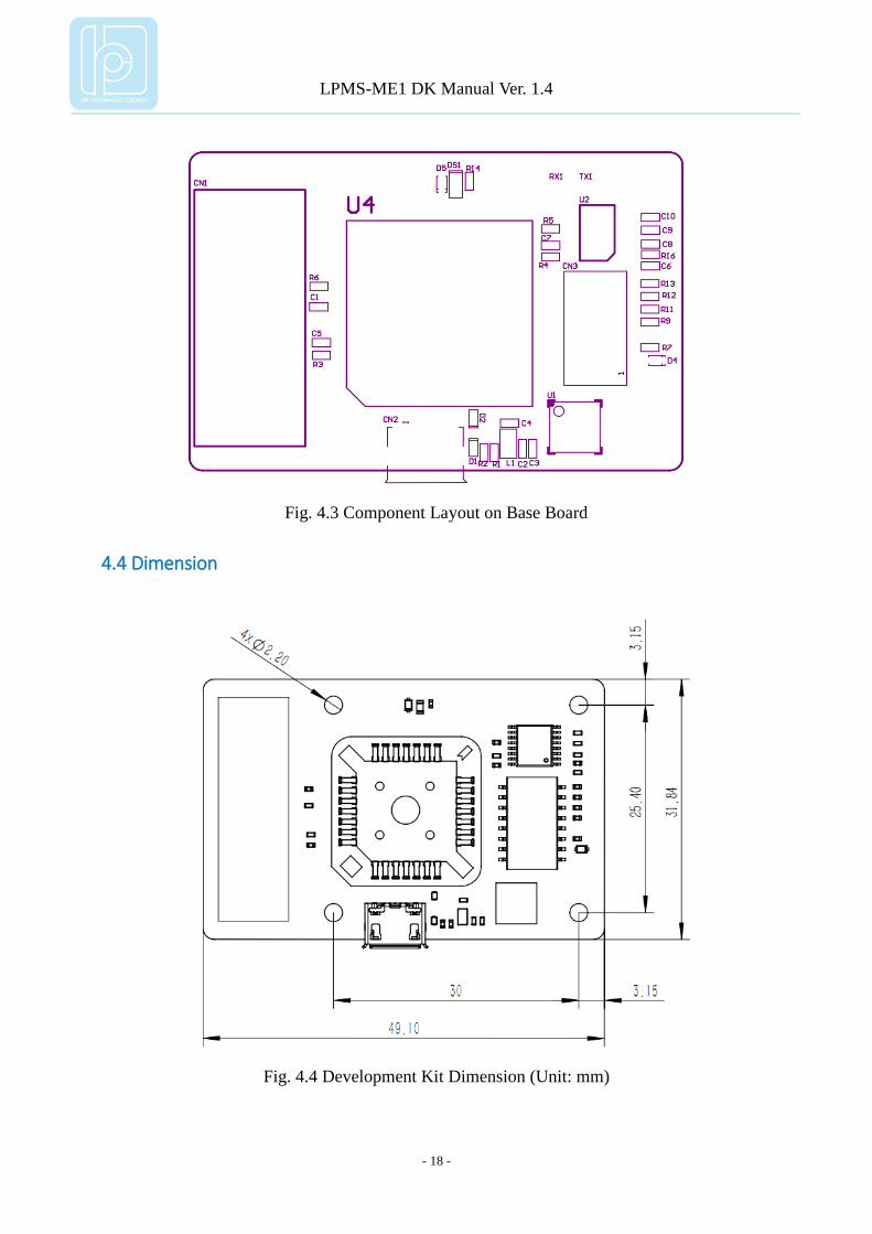
Fig. 4.3 Component Layout on Base Board
4.4 Dimension
Fig. 4.4 Development Kit Dimension (Unit: mm)

LPMS-ME1 DK Manual Ver. 1.4
- 19 -
4.5 Operation Condition
Table 4-4 Operation Condition
Item Value Unit
Power Supply 3.3~5.5 V
Working Temperature -40~85 °C
Copyright © 2017, LP-RESEARCH Inc. All rights reserved.
http://www.lp-research.com