Embed Size (px)
Citation preview

LP-GasServiceman’sManual
The LP-Gas Serviceman’s ManualEngineered Controls International, Inc., ECII®, has prepared this LP-Gas Serviceman’s Manual for use by installation servicemen and others requiring a handy reference for field service work. It deals with subjects that can be useful to field servicemen striving for greater efficiency and safer installations. For the more technical problems and theories, the many texts and manuals concerning the particular subject should be consulted.
This manual is not intended to conflict with fed-eral, state, or local ordinances and regulations. These should be observed at all times.
This information is intended to be forwarded throughout the product distribution chain. Additional copies are available from Engineered Controls International, Inc. and RegO® Products Master Distributors.
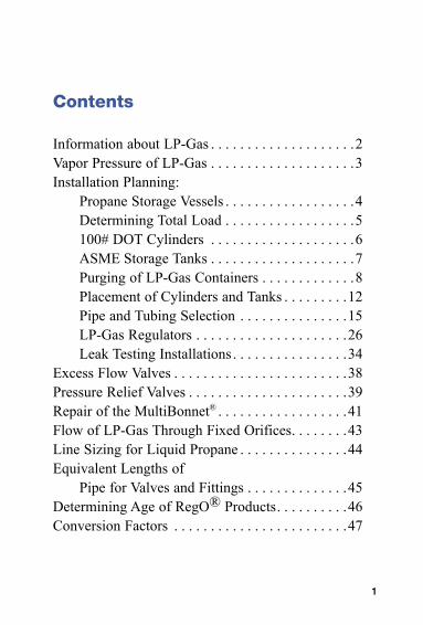
Contents
Information about LP-Gas . . . . . . . . . . . . . . . . . . . .2Vapor Pressure of LP-Gas . . . . . . . . . . . . . . . . . . . .3Installation Planning:
Propane Storage Vessels . . . . . . . . . . . . . . . . . .4Determining Total Load . . . . . . . . . . . . . . . . . .5100# DOT Cylinders . . . . . . . . . . . . . . . . . . . .6ASME Storage Tanks . . . . . . . . . . . . . . . . . . . .7Purging of LP-Gas Containers . . . . . . . . . . . . .8Placement of Cylinders and Tanks . . . . . . . . .12Pipe and Tubing Selection . . . . . . . . . . . . . . .15LP-Gas Regulators . . . . . . . . . . . . . . . . . . . . .26Leak Testing Installations . . . . . . . . . . . . . . . .34
Excess Flow Valves . . . . . . . . . . . . . . . . . . . . . . . .38Pressure Relief Valves . . . . . . . . . . . . . . . . . . . . . .39Repair of the MultiBonnet® . . . . . . . . . . . . . . . . . .41Flow of LP-Gas Through Fixed Orifices. . . . . . . .43Line Sizing for Liquid Propane . . . . . . . . . . . . . . .44Equivalent Lengths of
Pipe for Valves and Fittings . . . . . . . . . . . . . .45Determining Age of RegO® Products. . . . . . . . . .46Conversion Factors . . . . . . . . . . . . . . . . . . . . . . . .47
1
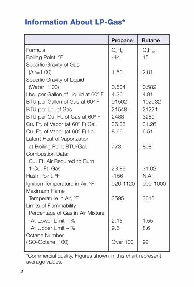
Information About LP-Gas*
Formula C3H8 C4H10
Boiling Point, ºF -44 15Specific Gravity of Gas (Air=1.00) 1.50 2.01
Specific Gravity of Liquid (Water=1.00) 0.504 0.582
Lbs. per Gallon of Liquid at 60º F 4.20 4.81BTU per Gallon of Gas at 60º F 91502 102032BTU per Lb. of Gas 21548 21221BTU per Cu. Ft. of Gas at 60º F 2488 3280Cu. Ft. of Vapor (at 60º F) Gal. 36.38 31.26Cu. Ft. of Vapor (at 60º F) Lb. 8.66 6.51Latent Heat of Vaporizationat Boiling Point BTU/Gal. 773 808
Combustion Data: Cu. Ft. Air Required to Burn1 Cu. Ft. Gas 23.86 31.02
Flash Point, ºF -156 N.A.Ignition Temperature in Air, ºF 920-1120 900-1000Maximum FlameTemperature in Air, ºF 3595 3615
Limits of Flammability Percentage of Gas in Air Mixture;At Lower Limit – % 2.15 1.55At Upper Limit – % 9.6 8.6
Octane Number (ISO-Octane=100) Over 100 92
*Commercial quality. Figures shown in this chart represent average values.
Propane Butane
2
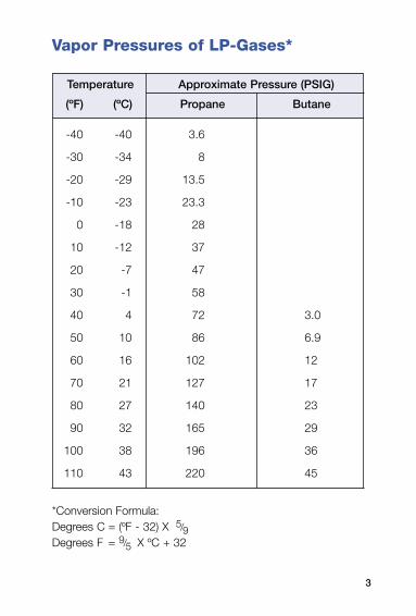
Vapor Pressures of LP-Gases*
-40 -40 3.6
-30 -34 8
-20 -29 13.5
-10 -23 23.3
0 -18 28
10 -12 37
20 -7 47
30 -1 58
40 4 72 3.0
50 10 86 6.9
60 16 102 12
70 21 127 17
80 27 140 23
90 32 165 29
100 38 196 36
110 43 220 45
*Conversion Formula:Degrees C = (ºF - 32) X 5/9Degrees F = 9/5 X ºC + 32
Temperature Approximate Pressure (PSIG)
(ºF) (ºC) Propane Butane
3
Propane Storage VesselsThe withdrawal of propane vapor from a vessel lowers the contained pressure. This causes the liquid to “boil” in an effort to restore the pressure by generating vapor to replace that which was withdrawn. The required “latent heat of vaporization” is surrendered by the liquid and causes the temperature of the liquid to drop as a result of the heat so expended.The heat lost due to the vaporization of the liquid is replaced by the heat in the air surrounding the container. This heat is transferred from the air through the metal surface of the vessel into the liquid. The area of the vessel in contact with vapor is not considered because the heat absorbed by the vapor is negligible. The surface area of the vessel that is bathed in liquid is known as the “wetted surface.” The greater this wetted surface, or in other words the greater the amount of liquid in the vessel, the greater the vaporization capacity of the system. A larger container would have a larger wetted surface area and therefore would have greater vaporizing capacity. If the liquid in the vessel receives heat for vaporization from the outside air, the higher the outside air temperature, the higher the vapor-ization rate of the system. How all this affects the vapor-ization rate of 100-pound cylinders is shown on page 6. It will be noted from this chart that the worst conditions for vaporization rate are when the container has a small amount of liquid in it and the outside air temperature is low.With the principles stated above in mind, simple formulae for determining the proper number of DOT cylinders and proper size of ASME storage containers for various loads where temperatures may reach 0ºF will be found on pages 6 and 7 respectively.
4
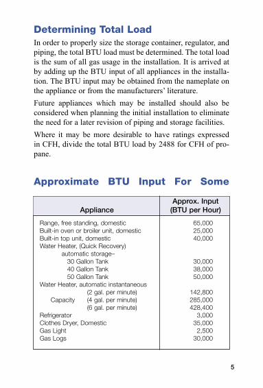
Determining Total LoadIn order to properly size the storage container, regulator, and piping, the total BTU load must be determined. The total load is the sum of all gas usage in the installation. It is arrived at by adding up the BTU input of all appliances in the installa-tion. The BTU input may be obtained from the nameplate on the appliance or from the manufacturers’ literature.Future appliances which may be installed should also be considered when planning the initial installation to eliminate the need for a later revision of piping and storage facilities.Where it may be more desirable to have ratings expressed in CFH, divide the total BTU load by 2488 for CFH of pro-pane.
Approximate BTU Input For Some
Range, free standing, domestic 65,000Built-in oven or broiler unit, domestic 25,000Built-in top unit, domestic 40,000Water Heater, (Quick Recovery)
automatic storage–30 Gallon Tank 30,00040 Gallon Tank 38,00050 Gallon Tank 50,000
Water Heater, automatic instantaneous (2 gal. per minute) 142,800
Capacity (4 gal. per minute) 285,000 (6 gal. per minute) 428,400
Refrigerator 3,000Clothes Dryer, Domestic 35,000Gas Light 2,500Gas Logs 30,000
Approx. Input Appliance (BTU per Hour)
5

100 LB. CylindersHow Many Are Required
“Rule of Thumb” Guide forInstalling 100 Lb. Cylinders
For continuous draws where temperatures may reach 0ºF. Assume the vaporization rate of a 100 lb. cylin-der as approximately 50,000 BTU per hour.
Number of cylinders per side = Total load in BTU 50,000
Example:
Assume total load = 200,000 BTU/hr.
Cylinders per side = 200,000 = 4 cylinders per side 50,000
Vaporization Rate - 100 Lb. Propane Cylinders(Approximate)
This chart shows the vaporization rate of containers in terms of the temperature of the liquid and the wet surface area of the container. When the temperature is lower of if the container has less liquid in it, the vaporization rate of the container is a lower value.
100 113,000 167,000 214,000 277,000 300,000 90 104,000 152,000 200,000 247,000 277,000 80 94,000 137,000 180,000 214,000 236,000 70 83,000 122,000 160,000 199,000 214,000 60 75,000 109,000 140,000 176,000 192,000 50 64,000 94,000 125,000 154,000 167,000 40 55,000 79,000 105,000 131,000 141,000 30 45,000 66,000 85,000 107,000 118,000 20 36,000 51,000 68,000 83,000 92,000 10 28,000 38,000 49,000 60,000 66,000
Lbs. of Maximum Continuous Draw In BTU Per Hour At Propane Various Temperatures In Degrees F. In Cyl. 0ºF 20ºF 40ºF 60ºF 70ºF
6
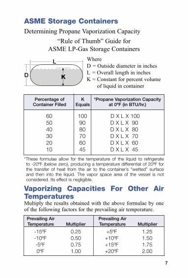
ASME Storage ContainersDetermining Propane Vaporization Capacity
“Rule of Thumb” Guide forASME LP-Gas Storage Containers
WhereD = Outside diameter in inchesL = Overall length in inchesK = Constant for percent volume
of liquid in container
60 100 D X L X 100 50 90 D X L X 90 40 80 D X L X 80 30 70 D X L X 70 20 60 D X L X 60 10 45 D X L X 45
*These formulae allow for the temperature of the liquid to refrigerate to -20ºF (below zero), producing a temperature differential of 20ºF for the transfer of heat from the air to the container’s “wetted” surface and then into the liquid. The vapor space area of the vessel is not considered. Its effect is negligible.
Vaporizing Capacities For Other Air TemperaturesMultiply the results obtained with the above formulae by one of the following factors for the prevailing air temperature.
-15ºF 0.25 +5ºF 1.25 -10ºF 0.50 +10ºF 1.50 -5ºF 0.75 +15ºF 1.75 0ºF 1.00 +20ºF 2.00
Percentage of K *Propane Vaporization Capacity Container Filled Equals at 0ºF (in BTU/hr.)
Prevailing Air Prevailing Air Temperature Multiplier Temperature Multiplier
7
Proper Purging of LP-Gas ContainersThe Importance of PurgingA very important step which must not be overlooked by LP-Gas distributors is the importance of properly purging new LP-Gas containers. Attention to this important procedure will promote customer satisfaction and greatly reduce service calls on new installations. Consider the following: • Both ASME and DOT specifications require hydrostatic
testing of vessels after fabrication. This is usually done with water.
• Before charging with propane, the vessel will contain the normal amount of air.
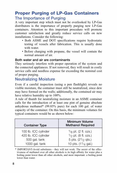
Both water and air are contaminantsThey seriously interfere with proper operation of the system and the connected appliances. If not removed, they will result in costly service calls and needless expense far exceeding the nominal cost of proper purging.Neutralizing MoistureEven if a careful inspection (using a pen flashlight) reveals no visible moisture, the container must still be neutralized, since dew may have formed on the walls; additionally, the contained air may have relative humidity up to 100%.A rule of thumb for neutralizing moisture in an ASME container calls for the introduction of at least one pint of genuine absolute anhydrous methanol* (99.85% pure) for each 100 gal. of water capacity of the container. On this basis, the minimum volumes for typical containers would be as shown below:
100 lb. ICC cylinder 1/8 pt. (2 fl. ozs.) 420 lb. ICC cylinder 1/2 pt. (8 fl. ozs.) 500 gal. tank 5 pts. (21/2 qts.) 1000 gal. tank 10 pts. (11/4 gal.)
* IMPORTANT-Avoid substitutes - they will not work. The secret of the effec-tiveness of methanol over all other alcohols is its high affinity for water plus a boiling point lower than all other alcohols, and most important: a boiling point lower than water.
Container Type
Minimum Volume Methanol Required
8
Proper Purging of LP-Gas ContainersThe Importance of Purging AirIf the natural volume of atmosphere in the vessel is not removed before the first fill, these problems will result:
• Installations made in spring and summer will experience excessive and false container pressures. This will cause the safety relief valve to open, blowing off the excess pressure.
• The air mixture present in the vapor space will be carried to the appliances. This may result in as many as 5 or more service calls from pilot light extinguishment.
• If a vapor return equalizing hose is not used, the contained air will be compressed above the liquid level, resulting in slow filling.
• If a vapor equalizing hose is used, the air, and any moisture it contains, will be transferred from the storage tank to the transport.
Additionally, if atmospheric air is properly purged from the storage tank;
• the storage tank will fill faster,• appliances will perform more consistently• relief valves will be less likely to pop off at consumer
installations.
Never Purge with LiquidThe wrong way is of course the easiest way. Never purge a container with liquid propane. To do so causes the liquid to flash into vapor, chilling the container, and condensing any moisture vapor on the walls where it remains while the pres-sure is being blown down. Additionally, less than 50% or as little as 25% of the air will be removed by this easy but wrong method.The correct procedure for purging air is shown on the following page.
9
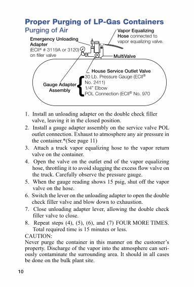
Proper Purging of LP-Gas ContainersPurging of Air
1. Install an unloading adapter on the double check filler valve, leaving it in the closed position.
2. Install a gauge adapter assembly on the service valve POL outlet connection. Exhaust to atmosphere any air pressure in the container.*(See page 11)
3. Attach a truck vapor equalizing hose to the vapor return valve on the container.
4. Open the valve on the outlet end of the vapor equalizing hose, throttling it to avoid slugging the excess flow valve on the truck. Carefully observe the pressure gauge.
5. When the gauge reading shows 15 psig, shut off the vapor valve on the hose.
6. Switch the lever on the unloading adapter to open the double check filler valve and blow down to exhaustion.
7. Close unloading adapter lever, allowing the double check filler valve to close.
8. Repeat steps (4), (5), (6), and (7) FOUR MORE TIMES. Total required time is 15 minutes or less.
CAUTION: Never purge the container in this manner on the customer’s property. Discharge of the vapor into the atmosphere can seri-ously contaminate the surrounding area. It should in all cases be done on the bulk plant site.
Gauge Adapter Assembly {
MultiValve
House Service Outlet Valve
Vapor Equalizing Hose connected to vapor equalizing valve.Emergency Unloading
Adapter(ECII® # 3119A or 3120) on filler valve
10
30 Lb. Pressure Gauge (ECII® No. 2411)1/4” ElbowPOL Connection (ECII® No. 970
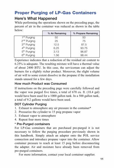
Proper Purging of LP-Gas ContainersHere’s What HappenedWhile performing the operations shown on the preceding page, the percent of air in the container was reduced as shown in the table below:
Experience indicates that a reduction of the residual air content to 6.25% is adequate. The resulting mixture will have a thermal value of about 2400 BTU. In this case, the serviceman can adjust the burners for a slightly richer product. Moreover, the slight volume of air will to some extent dissolve in the propane if the installation stands unused for a few days.How much Product was ConsumedIf instructions on the preceding page were carefully followed and the vapor was purged five times, a total of 670 cu. ft. (18.4 gal) would have been used for a 1000 gallon tank. In a 500 gallon tank, a total of 9.2 gallons would have been used.DOT Cylinder Purging1. Exhaust to atmosphere any air pressure in the container*2. Pressurize the cylinder to 15 psig propane vapor3. Exhaust vapor to atmosphere4. Repeat four more times* Pre-Purged containersFor LP-Gas containers that are purchased pre-purged it is not necessary to follow the purging procedure previously shown in this handbook. Simply attach an adapter onto the POL service connection and introduce propane vapor into the container. Allow container pressure to reach at least 15 psig before disconnecting the adapter. Air and moisture have already been removed from pre-purged containers.
For more information, contact your local container supplier.
1st Purging 50 50 2nd Purging 25 75 3rd Purging 12.5 87.5 4th Purging 6.25 93.75 5th Purging 3.13 96.87 6th Purging 1.56 98.44
% Air Remaining % Propane Remaining
11
Proper Placement of Cylinders and Tanks
After the proper number of DOT cylinders or proper size of ASME storage containers has been determined, care must be taken in selecting the most accessible, but “safety approved” site for their location.
Consideration should be given to the customer’s desires as to location of LP-Gas containers, and the ease of exchanging cylinders of refilling the storage tanks with the delivery truck––BUT precedence must be given to state and local regulations and NFPA 58, Liquefied Petroleum Gas Code. Refer to this standard when plan-ning placement of LP-Gas containers. Copies are available from the National Fire Protection Association, Batterymarch Park, Quincy, MA 02269.
The charts on the following pages are reprinted with permission of NFPA 58-1998, LP-Gas Code, Copyright © 1998, National Fire Protection Association, Quincy, MA 02269. This reprinted material is not the complete and official position of the NFPA on the referenced subject which is represented only by the standard in its entirety.
12
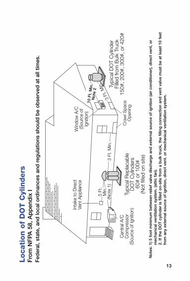
Locati
on
of
DO
T C
ylin
ders
Fro
m N
FP
A 5
8, A
pp
end
ix I
Fed
eral
, sta
te, a
nd lo
cal o
rdin
ance
s an
d r
egul
atio
ns s
houl
d b
e o
bse
rved
at
all t
imes
.
10 F
t. M
in.
Not
e 2
No
tes:
1) 5
fo
ot
min
imum
bet
wee
n re
lief
valv
e d
isch
arg
e an
d e
xter
nal s
our
ce o
f ig
nitio
n (a
ir c
ond
itio
ner)
, dire
ct v
ent,
or
mec
hani
cal v
entil
atio
n sy
stem
. (at
tic f
an).
2.
If t
he D
OT
cyl
ind
er is
fill
ed o
n-si
te f
rom
a b
ulk
truc
k, t
he f
illin
g c
onn
ectio
n an
d v
ent
valv
e m
ust
be
at le
ast
10 f
eet
fro
m a
ny e
xter
nal s
our
ce o
f ig
nitio
n, d
irect
ven
t. o
r m
echa
nica
l ven
tilat
ion
syst
em.
13
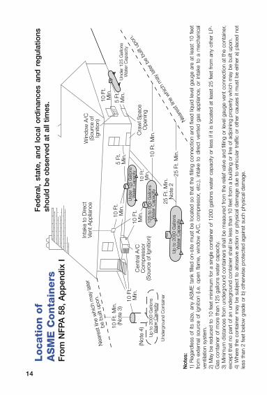
Locati
on
of
A
SM
E C
on
tain
ers
Fro
m N
FP
A 5
8, A
pp
end
ix I
No
tes:
1) R
egar
dles
s of
its
size
, an
y A
SM
E t
ank
fille
d on
-site
mus
t be
loca
ted
so t
hat
the
fillin
g co
nnec
tion
and
fixed
liqu
id le
vel g
auge
are
at
leas
t 10
fee
t fro
m e
xter
nal s
ourc
e of
igni
tion
(i.e.
ope
n fla
me,
win
dow
A/C
, co
mpr
esso
r, et
c.),
inta
ke t
o di
rect
ven
ted
gas
appl
ianc
e, o
r in
take
to
a m
echa
nica
l ve
ntila
tion
syst
em.
2) M
ay b
e re
duce
d to
10
feet
min
imum
for
a si
ngle
con
tain
er o
f 120
0 ga
llons
wat
er c
apac
ity o
r le
ss if
it is
loca
ted
at le
ast
25 fe
et fr
om a
ny o
ther
LP
-G
as c
onta
iner
of m
ore
than
125
gal
lons
wat
er c
apac
ity.
3) M
inim
um d
ista
nces
from
und
ergr
ound
con
tain
ers
shal
l be
mea
sure
d fro
m t
he r
elie
f val
ve a
nd fi
lling
or le
vel g
auge
ven
t co
nnec
tion
at t
he c
onta
iner
, ex
cept
tha
t no
par
t of
an
unde
rgro
und
cont
aine
r sh
all b
e le
ss t
han
10 fe
et fr
om a
bui
ldin
g or
line
of a
djoi
ning
pro
pert
y w
hich
may
be
built
upo
n.4)
Whe
re t
he c
onta
iner
may
be
subj
ect
to a
bras
ive
actio
n or
phy
sica
l dam
age
due
to v
ehic
ular
tra
ffic
or o
ther
cau
ses
it m
ust
be e
ither
a) p
lace
d no
t le
ss t
han
2 fe
et b
elow
gra
de o
r b)
oth
erw
ise
prot
ecte
d ag
ains
t su
ch p
hysi
cal d
amag
e.
14
5 Ft
.M
in.
Fed
eral
, st
ate,
and
lo
cal
ord
inan
ces
and
reg
ulat
ions
sh
oul
d b
e o
bse
rved
at
all t
imes
.
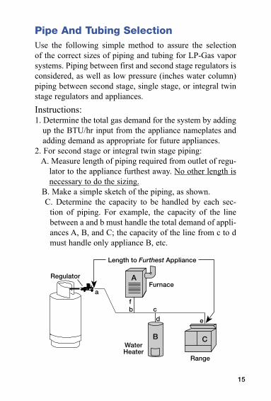
Pipe And Tubing SelectionUse the following simple method to assure the selection of the correct sizes of piping and tubing for LP-Gas vapor systems. Piping between first and second stage regulators is considered, as well as low pressure (inches water column) piping between second stage, single stage, or integral twin stage regulators and appliances.Instructions:1. Determine the total gas demand for the system by adding
up the BTU/hr input from the appliance nameplates and adding demand as appropriate for future appliances.
2. For second stage or integral twin stage piping: A. Measure length of piping required from outlet of regu-
lator to the appliance furthest away. No other length is necessary to do the sizing.
B. Make a simple sketch of the piping, as shown. C. Determine the capacity to be handled by each sec-
tion of piping. For example, the capacity of the line between a and b must handle the total demand of appli-ances A, B, and C; the capacity of the line from c to d must handle only appliance B, etc.
15
Pipe And Tubing Selection
D. Using Table 3 select proper size of tubing or pipe for each section of piping, using values in BTU/hr for the length determined from step #2-A. If exact length is not on chart, use next longer length. Do not use any other length for this purpose! Simply select the size that shows at least as much capacity as needed for each piping section.
3. For piping between first and second stage regulators A. For a simple system with only one second stage regula-
tor, merely measure length of piping required between outlet of first stage regulator and inlet of second stage regulator. Select piping or tubing required from Table 1.
B. For systems with multiple second stage regulators, measure length of piping required to reach the second stage regulator that is furthest away. Make a simple sketch, and size each leg of piping using Table 1, 2, or 3 using values shown in column corresponding to the length as measured above, same as when handling second stage piping.
16
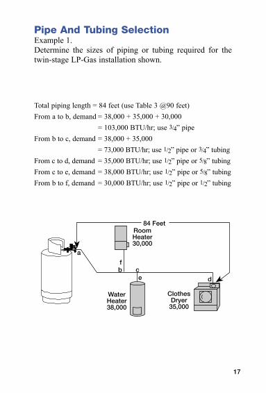
Pipe And Tubing SelectionExample 1.Determine the sizes of piping or tubing required for the twin-stage LP-Gas installation shown.
Total piping length = 84 feet (use Table 3 @90 feet)From a to b, demand = 38,000 + 35,000 + 30,000 = 103,000 BTU/hr; use 3/4” pipe From b to c, demand = 38,000 + 35,000 = 73,000 BTU/hr; use 1/2” pipe or 3/4” tubingFrom c to d, demand = 35,000 BTU/hr; use 1/2” pipe or 5/8” tubingFrom c to e, demand = 38,000 BTU/hr; use 1/2” pipe or 5/8” tubingFrom b to f, demand = 30,000 BTU/hr; use 1/2” pipe or 1/2” tubing
17
ClothesDryer
35,000
WaterHeater38,000
84 Feet
a
b cd
f
e
RoomHeater30,000
18
Pipe And Tubing Selection
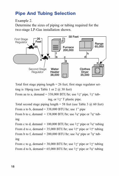
Example 2.Determine the sizes of piping or tubing required for the two-stage LP-Gas installation shown.
Total first stage piping length = 26 feet; first stage regulator set-ting is 10psig (use Table 1 or 2 @ 30 feet)From aa to a, demand = 338,000 BTU/hr; use 1/2” pipe, 1/2” tub-
ing, or 1/2” T plastic pipe.Total second stage piping length = 58 feet (use Table 3 @ 60 feet)From a to b, demand = 338,000 BTU/hr; use 1” pipeFrom b to c, demand = 138,000 BTU/hr; use 3/4” pipe or 7/8” tub-ingFrom c to d, demand = 100,000 BTU/hr; use 1/2” pipe or 3/4” tubingFrom d to e, demand = 35,000 BTU/hr; use 1/2” pipe or 1/2” tubingFrom b to f, demand = 200,000 BTU/hr; use 3/4” pipe or 7/8” tub-ingFrom c to g, demand = 38,000 BTU/hr; use 1/2” pipe or 1/2” tubingFrom d to h, demand = 65,000 BTU/hr; use 1/2” pipe or 5/8” tubing
Furnace200,000
ClothesDryer
35,000
WaterHeater38,000
58 Feet
aa
b c d
e
f
Range65,000
ha
a g
26Feet
First StageRegulator
Second StageRegulator
19
Pipe And Tubing Selection
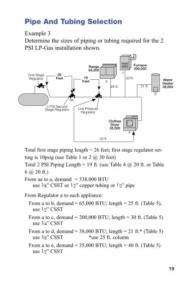
Example 3Determine the sizes of piping or tubing required for the 2 PSI LP-Gas installation shown.
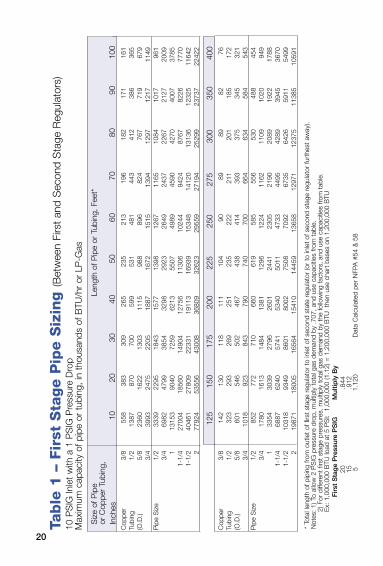
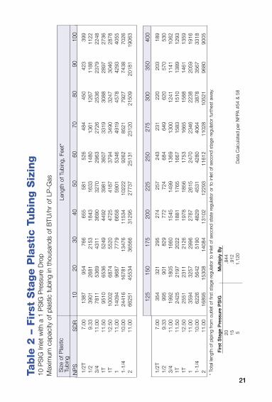
Total first stage piping length = 26 feet; first stage regulator set-ting is 10psig (use Table 1 or 2 @ 30 feet)Total 2 PSI Piping Length = 19 ft. (use Table 4 @ 20 ft. or Table 6 @ 20 ft.)From aa to a, demand = 338,000 BTU
use 3/8” CSST or 1/2” copper tubing or 1/2” pipe
From Regulator a to each appliance:From a to b, demand = 65,000 BTU; length = 25 ft. (Table 5),
use 1/2” CSSTFrom a to c, demand = 200,000 BTU; length = 30 ft. (Table 5)
use 3/4” CSSTFrom a to d, demand = 38,000 BTU; length = 21 ft.* (Table 5)
use 3/8” CSST *use 25 ft. columnFrom a to e, demand = 35,000 BTU; length = 40 ft. (Table 5)
use 1/2” CSST
Furnace200,000
ClothesDryer
35,000
WaterHeater38,000
Range65,000
2 PSI SecondStage Regulator Line Pressure
Regulator
c
d
e
aa
a
b
25 ft.
30 ft.
21 ft.
40 ft.
26Feet
First StageRegulator 19
Feet
20
Tab
le 1
– F
irst
Sta
ge P
ipe S
izin
g (B
etw
een
Firs
t an
d S
econ
d S
tage
Reg
ulat
ors)
10 P
SIG
Inle
t w
ith a
1 P
SIG
Pre
ssur
e D
rop
Max
imum
cap
acity
of p
ipe
or t
ubin
g, in
tho
usan
ds o
f BTU
/hr
or L
P-G
as
Cop
per
3/8
558
383
309
265
235
213
196
182
171
161
Tubi
ng
1/2
1387
87
0 70
0 59
9 53
1 48
1 44
3 41
2 38
6 36
5(O
.D.)
5/8
2360
16
22
1303
11
15
988
896
824
767
719
679
3/
4 39
93
2475
22
05
1887
16
72
1515
13
94
1297
12
17
1149
Pip
e S
ize
1/2
3339
22
95
1843
15
77
1398
12
67
1165
10
84
1017
96
1
3/4
6982
47
99
3854
32
98
2923
26
49
2437
22
67
2127
20
09
1 13
153
9040
72
59
6213
55
07
4989
45
90
4270
40
07
3785
1-
1/4
2700
4 18
560
1490
4 12
756
1130
6 10
244
9424
87
67
8226
77
70
1-1/
2 40
461
2780
9 22
331
1911
3 16
939
1534
8 14
120
1313
6 12
325
1164
2
2 77
924
5355
6 43
008
3680
9 32
623
2955
9 27
194
2529
9 23
737
2242
2
Cop
per
3/8
142
130
118
111
104
90
89
89
82
76Tu
bing
1/
2 32
3 29
3 26
9 25
1 23
5 22
2 21
1 20
1 18
5 17
2(O
.D.)
5/8
601
546
502
467
438
414
393
375
345
321
3/
4 10
18
923
843
790
740
700
664
634
584
543
Pip
e S
ize
1/2
852
772
710
660
619
585
556
530
488
454
3/
4 17
80
1613
14
84
1381
12
96
1224
11
62
1109
10
20
949
1
3354
30
39
2796
26
01
2441
23
05
2190
20
89
1922
17
88
1-1/
4 68
87
6240
57
41
5340
50
11
4733
44
95
4289
39
45
3670
1-
1/2
1031
8 93
49
8601
80
02
7508
70
92
6735
64
26
5911
54
99
2 19
871
1800
5 16
564
1541
0 14
459
1365
8 12
971
1237
5 11
385
1059
1
Siz
e of
Pip
e Le
ngth
of P
ipe
or T
ubin
g, F
eet*
or
Cop
per
Tubi
ng,
Inch
es
10
20
30
40
50
60
70
80
90
100
12
5 15
0 17
5 20
0 22
5 25
0 27
5 30
0 35
0 40
0
* To
tal l
engt
h of
pip
ing
from
out
let
of fi
rst
stag
e re
gula
tor
to in
let
of s
econ
d st
ate
regu
lato
r (o
r to
inle
t of
sec
ond
stag
e re
gula
tor
furt
hest
aw
ay).
Not
es: 1
) To
allo
w 2
PS
IG p
ress
ure
drop
, mul
tiply
tot
al g
as d
eman
d by
.707
, and
use
cap
aciti
es fr
om t
able
.
2) F
or d
iffer
ent
first
sta
ge p
ress
ures
, mul
tiply
tot
al g
as d
eman
d by
the
follo
win
g fa
ctor
s, a
nd u
se c
apac
ities
from
tab
le.
E
x: 1
,000
,000
BTU
load
at
5 P
SI:
1,0
00,0
00 (1
.12)
= 1
,200
,000
BTU
th
en u
se c
hart
bas
es o
n 1,
200,
000
BTU
Fir
st S
tag
e P
ress
ure
PS
IG
Mul
tiply
By
20
.8
44
15
.912
5
1.12
0 D
ata
Cal
cula
ted
per
NFP
A #
54 &
58
21
Tab
le 2
– F
irst
Sta
ge P
last
ic T
ubin
g S
izin
g
10 P
SIG
Inle
t w
ith a
1 P
SIG
Pre
ssur
e D
rop
Max
imum
cap
acity
of p
last
ic t
ubin
g in
tho
usan
ds o
f BTU
/hr
of L
P-G
as
1/2T
7.
00
1387
95
4 76
6 65
5 58
1 52
6 48
4 45
0 42
3 39
91/
2 9.
33
3901
26
81
2153
18
43
1633
14
80
1361
12
67
1188
11
223/
4 11
.00
7811
53
69
4311
36
90
3270
29
63
2726
25
36
2379
22
481T
11
.50
9510
65
36
5249
44
92
3981
36
07
3319
30
88
2897
27
361T
12
.50
1000
2 68
74
5520
47
25
4187
37
94
3490
32
47
3046
28
781
11.0
0 14
094
9687
77
79
6658
59
01
5346
49
19
4578
42
93
4055
1-1/
4 10
.00
2441
6 16
781
1347
6 11
534
1022
2 92
62
8521
79
27
7438
70
262
11.0
0 66
251
4553
4 36
566
3129
5 27
737
2513
1 23
120
2150
9 20
181
1906
3 1/
2T
7.00
35
4 32
1 29
5 27
4 25
7 24
3 23
1 22
0 20
3 18
91/
2 9.
33
995
901
829
772
724
684
649
620
570
530
3/4
11.0
0 19
92
1805
16
60
1545
14
99
1369
13
00
1241
11
41
1062
1T
11.5
0 24
25
2197
20
22
1881
17
65
1667
15
83
1510
13
89
1293
1T
12.5
0 25
51
2311
21
26
1978
18
56
1753
16
65
1588
14
61
1359
1 11
.00
3594
32
57
2996
27
87
2615
24
70
2346
22
38
2059
19
161-
1/4
10.0
0 62
26
5642
51
90
4829
45
31
4280
40
64
3878
35
67
3318
2 11
.00
1689
5 15
308
1408
4 13
102
1229
3 11
612
1102
8 10
521
9680
90
05
Siz
e of
Pla
stic
Le
ngth
of T
ubin
g, F
eet*
Tu
bing
NP
S
SD
R
10
20
30
40
50
60
70
80
90
100
12
5 15
0 17
5 20
0 22
5 25
0 27
5 30
0 35
0 40
0
* To
tal l
engt
h of
pip
ing
from
out
let
of fi
rst
stag
e re
gula
tor
to in
let
of s
econ
d st
ate
regu
lato
r or
to
inle
t of
sec
ond
stag
e re
gula
tor
furt
hest
aw
ay.
Fir
st S
tag
e P
ress
ure
PS
IG
Mul
tiply
By
20
.8
44
15
.912
5
1.12
0 D
ata
Cal
cula
ted
per
NFP
A #
54 &
58
Tab
le 3
– S
econ
d S
tage o
r In
tegra
l Tw
in S
tage P
ipe S
izin
g11
Inch
es W
ater
Col
umn
Inle
t w
ith a
1/2
Inch
Wat
er C
olum
n D
rop
Max
imum
cap
acity
of p
ipe
or t
ubin
g in
tho
usan
ds o
f BTU
/hr
of L
P-G
as
Cop
per
3/8
49
34
27
23
20
19
––
––
––
––Tu
bing
1/
2 11
0 76
61
52
46
42
38
36
33
32
(O.D
.) 5/
8 20
6 15
1 11
4 97
86
78
71
67
62
59
3/
4 34
8 23
9 19
2 16
4 14
6 13
2 12
0 11
3 10
5 10
0
7/8
536
368
296
253
224
203
185
174
161
154
Pip
e S
ize
1/2
291
200
161
137
122
110
102
94
87
84
3/4
608
418
336
287
255
231
212
198
185
175
1
1146
78
8 63
2 54
1 48
0 43
5 40
0 37
2 34
9 33
0
1-1/
4 23
53
1617
12
99
1111
98
5 89
2 82
1 76
4 71
7 67
7
1-1/
2 35
25
2423
19
46
1665
14
76
1337
12
30
1144
10
74
1014
2
6789
46
66
3747
32
07
2842
25
75
2369
22
04
2068
19
54
Cop
per
3/8
––
––
––
––
––
––
––
––
––
––Tu
bing
1/
2 ––
––
––
––
––
––
––
––
––
––
(O.D
.) 5/
8 ––
––
––
––
––
––
––
––
––
––
3/
4 ––
––
––
––
––
––
––
––
––
––
7/
8 ––
––
––
––
––
––
––
––
––
––
Pip
e S
ize
1/2
74
67
62
58
54
51
48
46
43
40
3/4
155
141
129
120
113
107
101
97
89
83
1 29
2 26
5 24
4 22
7 21
3 20
1 19
1 18
2 16
7 15
6
1-1/
4 60
0 54
4 50
0 46
5 43
7 41
2 39
2 37
4 34
4 32
0
Siz
e of
Pip
e Le
ngth
of P
ipe
or T
ubin
g, F
eet*
or
Cop
per
Tubi
ng,
Inch
es
10
20
30
40
50
60
70
80
90
100
12
5 15
0 17
5 20
0 22
5 25
0 27
5 30
0 35
0 40
0
* To
tal l
engt
h of
pip
ing
from
out
let
of r
egul
ator
to
appl
ianc
e fu
rthe
st a
way
.
Dat
a C
alcu
late
d pe
r N
FPA
#54
& 5
8
22
23
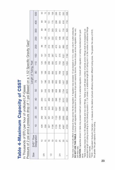
Tab
le 4
-Maxi
mu
m C
apacit
y of
CS
ST
In T
hous
ands
of B
TU p
er h
our
of u
ndilu
ted
LP-G
ases
P
ress
ure
of 2
psi
and
a p
ress
ure
drop
of 1
psi
(Bas
ed o
n a
1.52
Spe
cific
Gra
vity
Gas
)*
3/8
13
426
262
238
203
181
147
140
124
101
86
77
69
60
53
15
55
8 34
7 31
6 27
1 24
3 19
6 18
9 16
9 13
7 11
8 10
5 96
82
72
1/2
18
927
591
540
469
420
344
333
298
245
213
191
173
151
135
19
11
06
701
640
554
496
406
393
350
287
248
222
203
175
158
23
17
35
1120
10
27
896
806
663
643
578
477
415
373
343
298
268
3/4
25
2168
13
84
1266
11
00
986
809
768
703
575
501
448
411
355
319
30
40
97
2560
23
31
2012
17
94
1457
14
10
1256
10
21
880
785
716
616
550
1 31
47
20
2954
26
92
2323
20
72
1685
16
29
1454
11
82
1019
91
0 82
9 71
6 63
8
Le
ngth
of T
ubin
g, F
eet
Siz
e E
HD
** F
low
D
esig
natio
n 10
25
30
40
50
75
80
11
0 15
0 20
0 25
0 30
0 40
0 50
0
Tabl
e do
es n
ot in
clud
e ef
fect
of p
ress
ure
drop
acr
oss
the
line
regu
lato
r. If
regu
lato
r lo
ss e
xcee
ds 1
/2 p
si (b
ased
on
13 in
. wat
er c
olum
n ou
tlet
pres
sure
), D
O N
OT
US
E T
HIS
TA
BLE
. Con
sult
with
reg
ulat
or m
anuf
actu
rer
for
pres
sure
dro
ps a
nd c
apac
ity fa
ctor
s. P
ress
ure
drop
s ac
ross
a r
egul
ator
may
var
y w
ith fl
ow r
ate.
CA
UT
ION
: Cap
aciti
es s
how
n in
tab
le m
ay e
xcee
d m
axim
um c
apac
ity fo
r a
sele
cted
reg
ulat
or. C
onsu
lt w
ith r
egul
ator
or
tubi
ng m
anuf
actu
rer
for
guid
-an
ce.
*Tab
le in
clud
es lo
sses
for
four
90-
degr
ee b
ends
and
tw
o en
d fit
tings
. Tub
ing
runs
with
larg
er n
umbe
r of
ben
ds a
nd/o
r fit
tings
sha
ll be
incr
ease
d by
an
equi
vale
nt le
ngth
of t
ubin
g ac
cord
ing
to t
he fo
llow
ing
equa
tion:
L-1
.3n
whe
re L
is a
dditi
onal
leng
th (f
t) of
tub
ing
and
n is
the
num
ber
of a
dditi
onal
fitt
ings
an
d/or
ben
ds.
**E
HD
––
Equ
ival
ent
Hyd
raul
ic D
iam
eter
––
A m
easu
re o
f the
rel
ativ
e hy
drau
lic e
ffici
ency
bet
wee
n di
ffere
nt t
ubin
g si
zes.
The
gre
ater
the
val
ue o
f EH
D,
the
grea
ter
the
gas
capa
city
of t
he t
ubin
g.
24
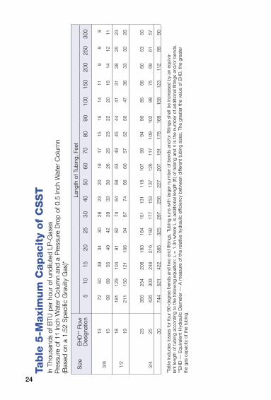
Tab
le 5
-Maxi
mu
m C
apacit
y of
CS
ST
In T
hous
ands
of B
TU p
er h
our
of u
ndilu
ted
LP-G
ases
P
ress
ure
of 1
1 In
ch W
ater
Col
umn
and
a P
ress
ure
Dro
p of
0.5
Inch
Wat
er C
olum
n (B
ased
on
a 1.
52 S
peci
fic G
ravi
ty G
as)*
3/8
13
72
50
39
34
30
28
23
20
19
17
15
15
14
11
9 8
8
15
99
69
55
49
42
39
33
30
26
25
23
22
20
15
14
12
11
1/2
18
181
129
104
91
82
74
64
58
53
49
45
44
41
31
28
25
23
19
21
1 15
0 12
1 10
6 94
87
74
66
60
57
52
50
47
36
33
30
26
23
35
5 25
4 20
8 18
3 16
4 15
1 13
1 11
8 10
7 99
94
90
85
66
60
53
50
3/4
25
426
303
248
216
192
177
153
137
126
117
109
102
98
75
69
61
57
30
74
4 52
1 42
2 36
5 32
5 29
7 25
6 22
7 20
7 19
1 17
8 16
9 15
9 12
3 11
2 99
90
Le
ngth
of T
ubin
g, F
eet
Siz
e E
HD
** F
low
D
esig
natio
n 5
10
15
20
25
30
40
50
60
70
80
90
100
150
200
250
300
*Tab
le in
clud
es lo
sses
for
four
90-
degr
ee b
ends
and
tw
o en
d fit
tings
. Tub
ing
runs
with
larg
er n
umbe
r of
ben
ds a
nd/o
r fit
tings
sha
ll be
incr
ease
d by
an
equi
va-
lent
leng
th o
f tub
ing
acco
rdin
g to
the
follo
win
g eq
uatio
n: L
= 1
.3n
whe
re L
is a
dditi
onal
leng
th (f
t) of
tub
ing
and
n is
the
num
ber
of a
dditi
onal
fitt
ings
and
/or
bend
s.**
EH
D –
– E
quiv
alen
t H
ydra
ulic
Dia
met
er –
– A
mea
sure
of t
he r
elat
ive
hydr
aulic
effi
cien
cy b
etw
een
diffe
rent
tub
ing
size
s. T
he g
reat
er t
he v
alue
of E
HD
, the
gre
ater
th
e ga
s ca
paci
ty o
f the
tub
ing.
25
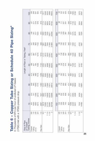
Tab
le 6
– C
op
per
Tube S
izin
g o
r S
chedule
40 P
ipe S
izin
g*
In T
hous
ands
of B
TU p
er h
our
of u
ndilu
ted
LP-G
ases
2
PS
IG in
let
with
a 1
PS
IG p
ress
ure
drop
Cop
per
3/8
451
310
249
213
189
171
157
146
137
130
Tubi
ng
1/2
1020
70
1 56
3 48
2 42
7 38
7 35
6 33
1 31
1 29
4(O
.D.)
5/8
1900
13
06
1049
89
8 79
5 72
1 66
3 61
7 57
9 54
7
3/4
3215
22
10
1774
15
19
1346
12
19
1122
10
44
979
925
Pip
e S
ize
1/2
2687
18
47
1483
12
69
1125
10
19
938
872
819
773
3/
4 56
19
3862
31
01
2654
23
52
2131
19
61
1824
17
12
1617
1
1058
5 72
75
5842
50
00
4431
40
15
3694
34
36
3224
30
46
1-1/
4 21
731
1493
6 11
994
1026
5 90
98
8243
75
84
7055
66
20
6253
1-
1/2
3256
0 22
378
1797
1 15
381
1363
2 12
351
1136
3 10
571
9918
93
69
2 62
708
4309
9 34
610
2962
1 26
253
2378
7 21
884
2035
9 19
102
1804
3
Cop
per
3/8
104
89
79
72
66
61
58
54
49
45Tu
bing
1/
2 23
6 20
2 17
9 16
2 14
9 13
9 13
0 12
3 11
1 10
2(O
.D.)
5/8
439
376
333
302
278
258
242
229
207
191
3/
4 74
3 63
6 56
3 51
1 47
0 43
7 41
0 38
7 35
1 32
3
Pip
e S
ize
1/2
621
531
471
427
393
365
343
324
293
270
3/
4 12
98
1111
98
5 89
2 82
1 76
4 71
7 67
7 61
3 56
4
1 24
46
2093
18
55
1681
15
46
1439
13
50
1275
11
55
1063
1-
1/4
5021
42
98
3809
34
51
3175
29
54
2771
26
18
2372
21
82
1-
1/2
7524
64
39
5707
51
71
4757
44
26
4152
39
22
3554
32
70
2 14
490
1240
1 10
991
9959
91
62
8523
79
97
7554
68
44
6297
Siz
e of
Pip
e Le
ngth
of P
ipe
or T
ubin
g, F
eet*
or
Cop
per
Tu
bing
, Inc
hes
10
20
30
40
50
60
70
80
90
100
15
0 20
0 25
0 30
0 35
0 40
0 45
0 50
0 60
0 70
0
26
LP-Gas RegulatorsThe regulator truly is the heart of an LP-Gas installation. It must compensate for variations in tank pressure from as low as 8 psig to 220 psig – and still deliver a steady flow of LP-Gas at 11” w.c. to consuming appliances. The regulator must deliver this pressure despite a variable load from intermittent use of the appliances.The use of a two-stage system offers the ultimate in pin-point regulation. Two-stage regulation can result in a more profitable LP-Gas operation for the dealer resulting from less maintenance and fewer installation call-backs.Single Stage/Twin-Stage RegulationNFPA 58 (1998) states that single stage regulators shall not be installed in fixed piping systems. This requirement includes systems for appliances on RVs, motor homes, manufactured housing, and food service vehicles. In these cases a twin-stage regulator must be used. The requirements do not apply to small outdoor cooking appliances, such as gas grills, provided the input rating is 100,000 BTU/hr or less.Two Stage RegulationTwo-Stage regulation has these advantages:Uniform Appliance PressuresThe installation of a two-stage system–one high pressure regulator at the container to compensate for varied inlet pressures, and one low pressure regulator at the building to supply a constant deliv-ery pressure to the appliances–helps ensure maximum efficiency and trouble-free operation year round. Two-stage systems keep pressure variations within 1” w.c. at the appliances.Reduced Freeze-ups/Service CallsRegulator freeze-up occurs when moisture in the gas condenses and freezes on cold surfaces of the regulator nozzle. The nozzle becomes chilled when high pressure gas expands across it into the regulator body.Two-stage systems can greatly reduce the possibility of freeze-ups and resulting service calls as the expansion of gas from tank pressure to 11” w.c. is divided into two steps, with less chill-ing effect at each regulator. In addition, after the gas exits the first-stage regulator and enters the first-stage transmission line, it
27
LP-Gas Regulatorspicks up heat from the line, further reducing the possibility of second-stage freeze-up.Economy of InstallationIn a twin-stage system, transmission line piping between the con-tainer and the appliances must be large enough to accommodate the required volume of gas at 11”w.c.. In contrast, the line between the first and second-stage regulators in two-stage systems can be much smaller as it delivers gas at 10 psig to the second stage regulator. Often the savings in piping cost will pay for the second regulator.In localities where winter temperatures are extremely low, atten-tion should be given to the setting of the first stage regulator to avoid the possibility of propane vapors recondensing into liquid in the line downstream of the first-stage regulator. For instance, if temperatures reach as low as -20ºF, the first-stage regulator should not be set higher than 10 psig. If temperatures reach as low as -35ºF, the setting of the first-stage regulator should not be higher than 5 psig.As an additional benefit, older single-stage systems can be easily converted to two-stage systems using existing supply lines when they prove inadequate to meet added loads.Allowance for Future AppliancesA high degree of flexibility is offered in new installations of two-stage systems. Appliances can be added later to the present load–provided the high pressure regulator can handle the increase– by the addition of a second low pressure regulator. Since appliances can be regulated independently, demands from other parts of the installation will not affect their individual performances.
Regulator Lockup TroubleshootingThe Problem:A new, properly installed ECII® regulator has a high lock-up, does not lock up, or is creeping.This is often caused by foreign material on the regulator seat disc. Foreign material usually comes from system piping upstream of the regulator. This material prevents the inlet nipple from properly seating on the seat disc.The Solution:There is a simple procedure that can be completed in the field that will resolve the problems in most cases. This procedure should be

28
LP-Gas Regulatorsdone by qualified service personnel only.Once it has been determined that a new regulator has not properly locked up, the following steps should be followed:
Step 1Hold the neck of the regulator body securely with a wrench. Remove the inlet with a second wrench by turning clockwise (left hand thread).Save the inlet nipple and gasket for reassembly.
Step 2Inspect the regulator seat disc. Wipe it clean using a dry, clean cloth.Inspect the inlet nipple to be sure the seating surface is clean and not dam-aged.
Step 3Reinstall the inlet nipple and gasket by turning counterclockwise into neck of regulator (left hand thread). Hold the neck of the regulator body secure with a wrench. Tighten the inlet nipple into the regulator with a second wrench. Tighten to 35 ft/lbs torque–do not overtighten.Be careful not to damage threads.After completing these steps, be sure system piping is clean and that new pigtails are being used.Reinstall the regulator, check for leaks and properly check the system.
Hold neck of regulator securely with this wrench
Turn this wrench clockwise
Seat Disc
Inlet Nipple
Hold neck of regulator securely with this wrench
Turn this wrench counterclockwise
29
LP-Gas RegulatorsPigtailsIf you are replacing an old regulator, remember to replace the cop-per pigtail. The old pigtail may contain corrosion which can restrict flow. In addition, corrosion may flake off and wedge between the regulator orifice and seat disc–preventing proper lock-up at zero flow.Regulator Vents/InstallationThe elements, such as freezing rain, sleet, snow, ice, mud, or debris, can obstruct the vent and prevent the regulator from operat-ing properly. This can result in high pressure gas at the appliances resulting in explosion or fire.Regulator vents must be clear and fully open at all times. Regulators installed in accordance with NFPA #58 will meet these requirements.In general, regulators should be installed with the vent facing down and under a protective cover. Screened vents must be checked to see that the screen is in place at all times. If the vent is clogged or screen missing, cleaning of the vent and screen replacement is necessary. If there is evidence of foreign material inside the vent, the regulator should be replaced.In applications where the regulator employs a vent discharge pipe, be sure it is installed with the outlet down and protected with a screen or suppressor. See RegO® Products Safety Warning WB-1 for important warning information on regulators.
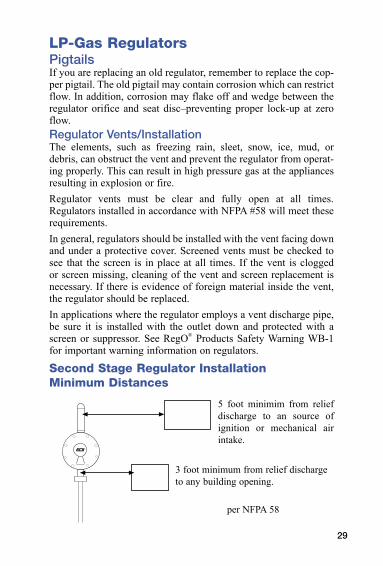
Second Stage Regulator Installation Minimum Distances
3 foot minimum from relief discharge to any building opening.
per NFPA 58
®
5 foot minimim from relief discharge to an source of ignition or mechanical air intake.
30
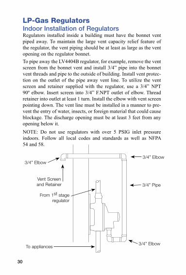
LP-Gas RegulatorsIndoor Installation of RegulatorsRegulators installed inside a building must have the bonnet vent piped away. To maintain the large vent capacity relief feature of the regulator, the vent piping should be at least as large as the vent opening on the regulator bonnet.To pipe away the LV4404B regulator, for example, remove the vent screen from the bonnet vent and install 3/4” pipe into the bonnet vent threads and pipe to the outside of building. Install vent protec-tion on the outlet of the pipe away vent line. To utilize the vent screen and retainer supplied with the regulator, use a 3/4” NPT 90º elbow. Insert screen into 3/4” F.NPT outlet of elbow. Thread retainer into outlet at least 1 turn. Install the elbow with vent screen pointing down. The vent line must be installed in a manner to pre-vent the entry of water, insects, or foreign material that could cause blockage. The discharge opening must be at least 3 feet from any opening below it.NOTE: Do not use regulators with over 5 PSIG inlet pressure indoors. Follow all local codes and standards as well as NFPA 54 and 58.
3/4” Elbow
3/4” Pipe
3/4” Elbow
3/4” Elbow
Vent Screen and Retainer
From 1st stage regulator
To appliances
31
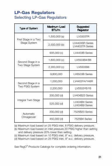
LP-Gas RegulatorsSelecting LP-Gas Regulators
(a) Maximum load based on 25 PSIG inlet, 8 PSIG delivery pressure.(b) Maximum load based on inlet pressure 20 PSIG higher than setting
and delivery pressure 20% lower than setting.(c) Maximum load based on 10 PSIG inlet, 9” w.c. delivery pressure.(d) Maximum load based on 25 PSIG inlet, 9” w.c. delivery pressure.
See RegO® Products Catalogs for complete ordering information.
metsySfoepyT metsySfoepyT metsySfoepyT metsySfoepyT metsySfoepyTdaoLmumixaM daoLmumixaM daoLmumixaM daoLmumixaM daoLmumixaM
.rh/UTB .rh/UTB .rh/UTB .rh/UTB .rh/UTBdetsegguS detsegguS detsegguS detsegguS detsegguSrotalugeR rotalugeR rotalugeR rotalugeR rotalugeR
owTaniegatStsriFmetsySegatS
)a(000,005,1 RT3033VL
)b(000,005,2seireSRS3044VLseireSRT3044VL
aniegatSdnoceSmetsySegatSowT
)c(000,539 seireSB3044VL
)c(000,006,1 6B/4B3055VL
)c(000,003,2 8B3055VL
000,008,9 seireSB3056VL
aniegatSdnoceSmetsySGISPowT
000,000,1 R64Y/4Y3044VL
000,002,2 8Y/6Y3055VL
egatSniwTlargetnI
)d(000,002 seireS32B404VL
)d(000,525seireS4B404VLseireS9B404VL
citamotuArevoeganhC
)d(000,002 seireS32B5257
)d(000,054 seireS4B5257
32
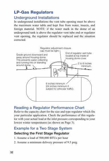
LP-Gas RegulatorsUnderground InstallationsIn underground installations the vent tube opening must be above the maximum water table and kept free from water, insects, and foreign material. NOTE: if the water mark in the dome of an underground tank is above the regulator vent tube end or regulator vent opening, the regulator should be replaced and the situation corrected.
Reading a Regulator Performance ChartRefer to the capacity chart for the size and type regulator which fits your particular application. Check the performance of this regula-tor with your actual load at the inlet pressure corresponding to your lowest winter temperatures (as shown on Page 3).
Example for a Two Stage SystemSelecting the First Stage Regulator1. Assume a load of 500,000 BTUs per hour2. Assume a minimum delivery pressure of 9.5 psig.
Grade ground downward andaway around housing dome.This prevents water collectingand running into or standingaround dome.
Regulator adjustment closurecap must be tight.
End of regulator vent tubelocated at top inside ofhousing dome cover.
2 to 6 inchesminimum.
6 inches minimum(24 inches minimum ifsubject to vehicular traffic).
33
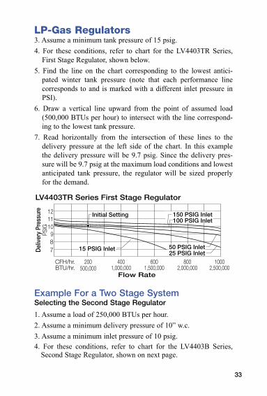
LP-Gas Regulators3. Assume a minimum tank pressure of 15 psig.4. For these conditions, refer to chart for the LV4403TR Series,
First Stage Regulator, shown below.5. Find the line on the chart corresponding to the lowest antici-
pated winter tank pressure (note that each performance line corresponds to and is marked with a different inlet pressure in PSI).
6. Draw a vertical line upward from the point of assumed load (500,000 BTUs per hour) to intersect with the line correspond-ing to the lowest tank pressure.
7. Read horizontally from the intersection of these lines to the delivery pressure at the left side of the chart. In this example the delivery pressure will be 9.7 psig. Since the delivery pres-sure will be 9.7 psig at the maximum load conditions and lowest anticipated tank pressure, the regulator will be sized properly for the demand.
Example For a Two Stage SystemSelecting the Second Stage Regulator
1. Assume a load of 250,000 BTUs per hour.2. Assume a minimum delivery pressure of 10” w.c.3. Assume a minimum inlet pressure of 10 psig.4. For these conditions, refer to chart for the LV4403B Series,
Second Stage Regulator, shown on next page.
50 PSIG Inlet25 PSIG Inlet
15 PSIG Inlet
150 PSIG Inlet100 PSIG Inlet
12
1011
987D
eliv
ery
Pres
sure
PSIG
200500,000
6001,500,000
4001,000,000
8002,000,000
10002,500,000
CFH/hr.BTU/hr.
LV4403TR Series First Stage Regulator
Initial Setting
Flow Rate
34
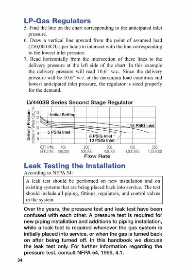
LP-Gas Regulators5. Find the line on the chart corresponding to the anticipated inlet
pressure.6. Draw a vertical line upward from the point of assumed load
(250,000 BTUs per hour) to intersect with the line corresponding to the lowest inlet pressure.
7. Read horizontally from the intersection of these lines to the delivery pressure at the left side of the chart. In this example the delivery pressure will read 10.6” w.c.. Since the delivery pressure will be 10.6” w.c. at the maximum load condition and lowest anticipated inlet pressure, the regulator is sized properly for the demand.
Leak Testing the InstallationAccording to NFPA 54:A leak test should be performed on new installation and on existing systems that are being placed back into service. The test should include all piping, fittings, regulators, and control valves in the system.
Over the years, the pressure test and leak test have been confused with each other. A pressure test is required for new piping installation and additions to piping installation, while a leak test is required whenever the gas system is initially placed into service, or when the gas is turned back on after being turned off. In this handbook we discuss the leak test only. For further information regarding the pressure test, consult NFPA 54, 1999, 4.1.
13
1112
1098D
eliv
ery
Pres
sure
Inch
es o
f Wat
er C
olum
n
100250,000
300750,000
200500,000
4001,000,000
5001,250,000
CFH/hr.BTU/hr.
LV4403B Series Second Stage Regulator
Initial Setting
5 PSIG Inlet
15 PSIG Inlet
Flow Rate
8 PSIG Inlet10 PSIG Inlet
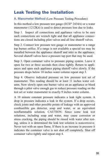
Leak Testing the InstallationA. Manometer Method (Low Pressure Testing Procedure)
In this method a low pressure test gauge (ECII® 2434A) or a water manometer (1212Kit) is used to detect pressure loss due to leaks.Step 1. Inspect all connections and appliance valves to be sure such connections are wrench tight and that all appliance connec-tions are closed including pilot valves and all line shutoff valves.
Step 2. Connect low pressure test gauge or manometer to a range top burner orifice. If a range is not available a special tee may be installed between the appliance shutoff and inlet to the appliance. Several shutoff valves have a pressure tap port that may be used.
Step 3. Open container valve to pressure piping system. Leave it open for two or three seconds then close tightly. Return to appli-ances and open each appliance piping shutoff valve slowly. If the pressure drops below 10 inches water column repeat step 3.
Step 4. Observe indicated pressure on low pressure test set of manometer. This reading should be at least 11 inches water col-umn. Now slowly open one burner valve on an appliance or bleed through a pilot valve enough gas to reduce pressure reading on the test set or water manometer to exactly 9 inches water column.
A 10 minute constant pressure indicates a leak tight system. A drop in pressure indicates a leak in the system. If a drop occurs, check joints and other possible points of leakage with an approved combustible gas detector, soap and water, or an equivalent nonflammable solution. CAUTION: Since some leak test solutions, including soap and water, may cause corrosion or stress cracking, the piping should be rinsed with water after test-ing, unless it is determined the leak test solution is noncorrosive. Never test with an open flame. If there is an increase in pressure it indicates the container valve is not shut off completely. Shut off container valve tightly and repeat step 4.
35
36
Leak Testing the InstallationB. Gauge Adapter Method (High Pressure Testing Procedure)Step 1. Inspect all connections and appliance valves to be sure such connections are wrench tight and that all appliance valves are closed including the pilot valves.Step 2. Install an ECII® 2962 high pressure test gauge adapter on the tank service valve and connect the other end of the gauge adapter to the pigtail and regulator inlet.Step 3. Open container valve to allow the system to pressurize while observing indicated pressure on 300 pound testing gauge.Step 4. Close service valve tightly. Note pressure reading on the pressure gauge, then slowly bleed gas between service valve and gauge adapter, reduce pressure to 10 PSIG less than the original reading on the gauge and retighten gauge adapter into service valve or close bleeder port. Note reading on gauge.If gauge reading remains constant for 10 minutes, it can be assumed the system is leak tight. If the pressure reading drops, it indicates a leak somewhere in the high or low pressure piping system. NOTE: A pressure drop of 15 psig in 10 minutes time indicates a leak as little as 10 BTU of gas per hour. Check joints and other possible points of leakage with an approved combus-tible gas detector, soap and water, or an equivalent nonflammable solution. CAUTION: Since some leak test solutions, including soap and water, may cause corrosion or stress cracking, the piping should be rinsed with water after testing, unless it is determined the leak test solution is noncorrosive. Never test with an open flame. If there is an increase in pressure it indicates the container valve is not shut off completely. Shut off container valve tightly and repeat step 4.Step 5. Disconnect the 2962 test gauge adapter from the service shut off valve. Reconnect pigtail, tighten and test with soap and water or an appropriate leak detector solution (refer to caution in step 4., above).Step 6. Proceed with manometer method, steps 2 through 4. Never check for leaks with an open flame.
37
Leak Testing the InstallationNOTE: After the piping system and appliance connections have been proven to be leak tight, the air may be purged from lines. Refer to NPGA Propane Safety and Technical Support Manual Bulletin T403 and NFPA 54 for more information.Regulator Delivery PressureCheck the regulator delivery pressure with approximately half the total appliance load in use. Your gauge should read 11 inches water column at the appliance. Adjust regulator if necessary. Following this, turn on all appliances to make sure that pressure is maintained at full load. If an excessive pressure drop occurs, inspect line for “kinks,” “flats,” or other restrictions.CAUTION: Appliance regulators are installed on most appliances and may be preset by the manufacturer for flow pressure lower than 11 inches water column. It is recommended the manometer or test gauge be installed at a location other than the range orifice or appliance pressure tap when performing lockup and delivery pressure checks.
Regulator Lock-up and LeakageAfter this, shut off all appliance valves to determine if the regula-tor has a worn seat or if it has been set too high to compensate for line losses due to undersize piping. A slight rise in pressure will occur under these conditions. This is called the “lock-up” pressure. The lock-up pressure should not exceed 130% of the regulator set delivery pressure. A quick rise in pressure above this point will indicate undersize piping.Continue this same test for 5 minutes or more. If a creeping rise is noticed in the pressure, the regulator seat is not closing off prop-erly. Inspect regulator inlet nozzle for dirt, scratches, or dents, and seat disc for signs of wear. Replace where necessary.For more information, refer to NFPA 54, Section on Inspection, Testing and Purging, NPGA Propane Safety and Technical Support Manual Bulletin 403, “Pressure testing and leak checking LP Gas piping systems.” For more information on setting single stage regu-lators, request RegO® Products Technical Guide 107.
38
Proper Use of Excess Flow ValvesThe primary purpose of an excess flow valve is to protect against excessive flow when breakage of pipe lines or hose rupture takes place. When we refer to breakage or rupture, a clean and complete separation is assumed. It is obvious that, if the damage is only a crack or if the piping is crushed at the point of failure, the escaping flow will be restricted and may or may not pass sufficient vapor or liquid to cause the excess flow valve to close.An excess flow valve, while in its normal open position, permits the flow of liquid or gas in either direction. Flow is controlled in one direction only. Each excess flow valve is stamped with an arrow showing the direction in which the flow is controlled. If the flow in that direction exceeds a predetermined rate the valve automatically closes. Manufacturers’ catalogs show the closing flow rating both in terms of liquid and vapor.Since excess flow valves depend on flow for closure, the line leading away from the excess flow valve should be large enough so that it will not excessively restrict the flow. If the pipe run is unusually long or restricted by numerous elbows, tees, or other fittings, consideration should be given to the use of larger size pipe and fittings. Never use a pipe size smaller than that of the excess flow valve.It is considered good practice to select an excess flow valve with a rated closing flow approximately 50% greater than the antici-pated normal flow. This is important because valves which have a closing flow very close to the normal flow may chatter or slug closed when surges in the line occur either during normal operation or due to the rapid opening of a control valve.Excess flow valves should be tested and proven at the time of installation and at periodic intervals not to exceed one year. The tests should include a simulated break in the line by the quick opening of a shutoff valve at the farthest possible point in the piping which the excess flow valve is intended to protect. If the valve closes under these conditions, it is reasonable to assume that it will close in the event of accidental breakage of the piping at any point closer to the excess flow valve.See RegO® Products Safety Warning WB-3 for important warning information
39
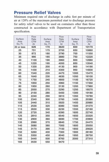
Pressure Relief ValvesMinimum required rate of discharge in cubic feet per minute of air at 120% of the maximum permitted start to discharge pressure for safety relief valves to be used on containers other than those constructed in accordance with Department of Transportation specification.
20 or less253035404550556065707580859095
100105110115120125130135140145150155160165
626751872990
11001220133014301540164017501850195020502150224023402440253026302720281029002990308031703260335034403530
170175180185190195200210220230240250260270280290300310320330340350360370380390400450500550
362037003790388039604050413043004470463048004960513052905450561057605920608062306390654066906840700071507300804087609470
600650700750800850900950
100010501100115012001250130013501400145015001550160016501700175018001850190019502000
1017010860115501222012880135401419014830154701610016720173501796018570191801978020380209802157022160227402332023900244702505025620261802675027310
SurfaceArea
Sq. Ft.
FlowRateCFM Air
Surface Area
Sq. Ft.
FlowRateCFMAir
Surface Area
Sq. Ft.
FlowRateCFMAir
40
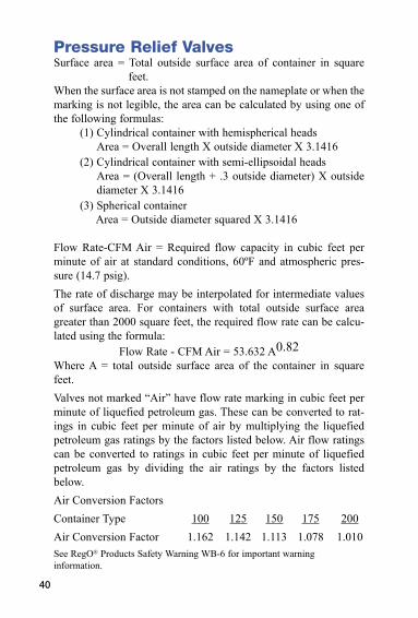
Pressure Relief ValvesSurface area = Total outside surface area of container in square
feet.When the surface area is not stamped on the nameplate or when the marking is not legible, the area can be calculated by using one of the following formulas:
(1) Cylindrical container with hemispherical headsArea = Overall length X outside diameter X 3.1416
(2) Cylindrical container with semi-ellipsoidal headsArea = (Overall length + .3 outside diameter) X outside diameter X 3.1416
(3) Spherical containerArea = Outside diameter squared X 3.1416
Flow Rate-CFM Air = Required flow capacity in cubic feet per minute of air at standard conditions, 60ºF and atmospheric pres-sure (14.7 psig).The rate of discharge may be interpolated for intermediate values of surface area. For containers with total outside surface area greater than 2000 square feet, the required flow rate can be calcu-lated using the formula:
Flow Rate - CFM Air = 53.632 A0.82Where A = total outside surface area of the container in square feet.Valves not marked “Air” have flow rate marking in cubic feet per minute of liquefied petroleum gas. These can be converted to rat-ings in cubic feet per minute of air by multiplying the liquefied petroleum gas ratings by the factors listed below. Air flow ratings can be converted to ratings in cubic feet per minute of liquefied petroleum gas by dividing the air ratings by the factors listed below.Air Conversion FactorsContainer Type 100 125 150 175 200Air Conversion Factor 1.162 1.142 1.113 1.078 1.010See RegO® Products Safety Warning WB-6 for important warning information.
41
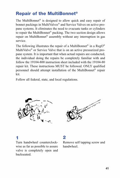
Repair of the MultiBonnet®
The MultiBonnet® is designed to allow quick and easy repair of bonnet packings in MultiValves® and Service Valves on active pro-pane systems. It eliminates the need to evacuate tanks or cylinders to repair the MultiBonnet® packing. The two section design allows repair on MultiBonnet® assembly without any interruption in gas service.The following illustrates the repair of a MultiBonnet® in a RegO® MultiValve® or Service Valve that is on an active pressurized pro-pane system. It is important that when actual repairs are conducted, the individual doing the repairs be completely familiar with and follow the 19104-800 instruction sheet included with the 19104-80 repair kit. These instructions MUST be followed. ONLY qualified personnel should attempt installation of the MultiBonnet® repair kit.Follow all federal, state, and local regulations.
1Turn handwheel counterclock-wise as far as possible to assure valve is completely open and backseated.
2Remove self tapping screw and handwheel.
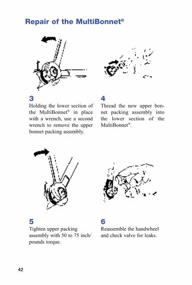
42
Repair of the MultiBonnet®
3Holding the lower section of the MultiBonnet® in place with a wrench, use a second wrench to remove the upper bonnet packing assembly.
4Thread the new upper bon-net packing assembly into the lower section of the MultiBonnet®.
5Tighten upper packing assembly with 50 to 75 inch/pounds torque.
6Reassemble the handwheel and check valve for leaks.
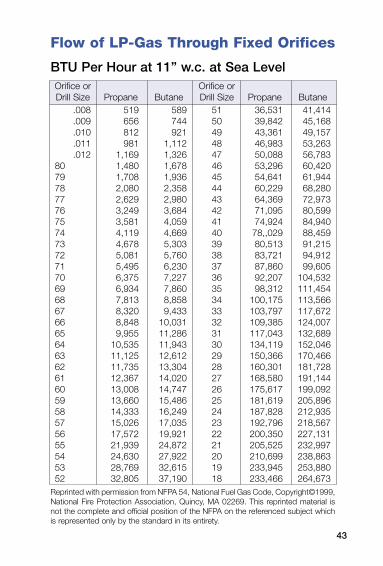
43
Flow of LP-Gas Through Fixed Orifices
BTU Per Hour at 11” w.c. at Sea Level
.008
.009
.010
.011
.0128079787776757473727170696867666564636261605958575655545352
519656812981
1,1691,4801,7082,0802,6293,2493,5814,1194,6785,0815,4956,3756,9347,8138,3208,8489,955
10,53511,12511,73512,36713,00813,66014,33315,02617,57221,93924,63028,76932,805
589744921
1,1121,3261,6781,9362,3582,9803,6844,0594,6695,3035,7606,2307,2277,8608,8589,433
10,03111,28611,94312,61213,30414,02014,74715,48616,24917,03519,92124,87227,92232,61537,190
51504948474645444342414039383736353433323130292827262524232221201918
36,53139,84243,36146,98350,08853,29654,64160,22964,36971,09574,92478,,02980,51383,72187,86092,20798,312
100,175103,797109,385117,043134,119150,366160,301168,580175,617181,619187,828192,796200,350205,525210,699233,945233,466
41,41445,16849,15753,26356,78360,42061,94468,28072,97380,59984,94088,45991,21594,91299,605
104,532111,454113,566117,672124,007132,689152,046170,466181,728191,144199,092205,896212,935218,567227,131232,997238,863253,880264,673
Orifice or Drill Size Propane Butane
Orifice or Drill Size Propane Butane
Reprinted with permission from NFPA 54, National Fuel Gas Code, Copyright©1999, National Fire Protection Association, Quincy, MA 02269. This reprinted material is not the complete and official position of the NFPA on the referenced subject which is represented only by the standard in its entirety.
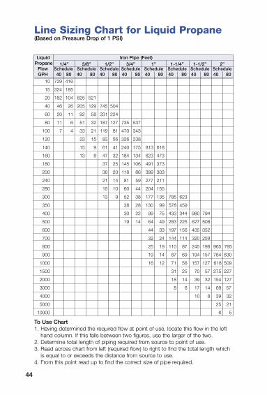
44
10 729 416
15 324 185
20 182 104 825 521
40 46 26 205 129 745 504
60 20 11 92 58 331 224
80 11 6 51 32 187 127 735 537
100 7 4 33 21 119 81 470 343
120 23 15 83 56 326 238
140 15 9 61 41 240 175 813 618
160 13 8 47 32 184 134 623 473
180 37 25 145 106 491 373
200 30 20 118 86 399 303
240 21 14 81 59 277 211
280 15 10 60 44 204 155
300 13 9 52 38 177 135 785 623
350 38 28 130 99 578 459
400 30 22 99 75 433 344 980 794
500 19 14 64 49 283 225 627 508
600 44 33 197 156 435 352
700 32 24 144 114 320 259
800 25 19 110 87 245 198 965 795
900 19 14 87 69 194 157 764 630
1000 16 12 71 56 157 127 618 509
1500 31 25 70 57 275 227
2000 18 14 39 32 154 127
3000 8 6 17 14 69 57
4000 10 8 39 32
5000 25 21
10000 6 5
Liquid Iron Pipe (Feet) Propane 1/4” 3/8” 1/2” 3/4” 1” 1-1/4” 1-1/2” 2” Flow Schedule Schedule Schedule Schedule Schedule Schedule Schedule Schedule GPH 40 80 40 80 40 80 40 80 40 80 40 80 40 80 40 80
To Use Chart1. Having determined the required flow at point of use, locate this flow in the left
hand column. If this falls between two figures, use the larger of the two.2. Determine total length of piping required from source to point of use.3. Read across chart from left (required flow) to right to find the total length which
is equal to or exceeds the distance from source to use.4. From this point read up to find the correct size of pipe required.
Line Sizing Chart for Liquid Propane(Based on Pressure Drop of 1 PSI)
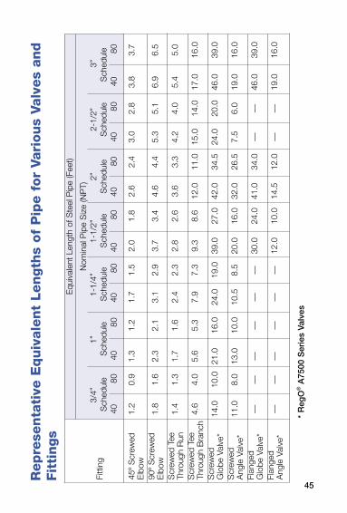
45
Rep
rese
nta
tive
Equiv
ale
nt
Length
s of
Pip
e f
or
Vari
ous
Valv
es
and
Fit
tin
gs
Fitt
ing
45º
Scr
ewed
1.
2 0.
9 1.
3 1.
2 1.
7 1.
5 2.
0 1.
8 2.
6 2.
4 3.
0 2.
8 3.
8 3.
7E
lbow
90º
Scr
ewed
1.
8 1.
6 2.
3 2.
1 3.
1 2.
9 3.
7 3.
4 4.
6 4.
4 5.
3 5.
1 6.
9 6.
5E
lbow
Scr
ewed
Tee
1.
4 1.
3 1.
7 1.
6 2.
4 2.
3 2.
8 2.
6 3.
6 3.
3 4.
2 4.
0 5.
4 5.
0Th
roug
h R
un
Scr
ewed
Tee
4.
6 4.
0 5.
6 5.
3 7.
9 7.
3 9.
3 8.
6 12
.0
11.0
15
.0
14.0
17
.0
16.0
Thro
ugh
Bra
nch
Scr
ewed
14
.0
10.0
21
.0
16.0
24
.0
19.0
39
.0
27.0
42
.0
34.5
24
.0
20.0
46
.0
39.0
Glo
be V
alve
*S
crew
ed
11.0
8.
0 13
.0
10.0
10
.5
8.5
20.0
16
.0
32.0
26
.5
7.5
6.0
19.0
16
.0A
ngle
Val
ve*
Flan
ged
––
––
––
––
––
––
30.0
24
.0
41.0
34
.0
––
––
46.0
39
.0G
lobe
Val
ve*
Flan
ged
––
––
––
––
––
––
12.0
10
.0
14.5
12
.0
––
––
19.0
16
.0A
ngle
Val
ve*
Equ
ival
ent
Leng
th o
f Ste
el P
ipe
(Fee
t)
Nom
inal
Pip
e S
ize
(NP
T)
3/4”
1”
1-
1/4”
1-
1/2”
2”
2-
1/2”
3”
S
ched
ule
Sch
edul
e S
ched
ule
Sch
edul
e S
ched
ule
Sch
edul
e S
ched
ule
40
80
40
80
40
80
40
80
40
80
40
80
40
80
* R
egO
® A
7500
Ser
ies
Valv
es
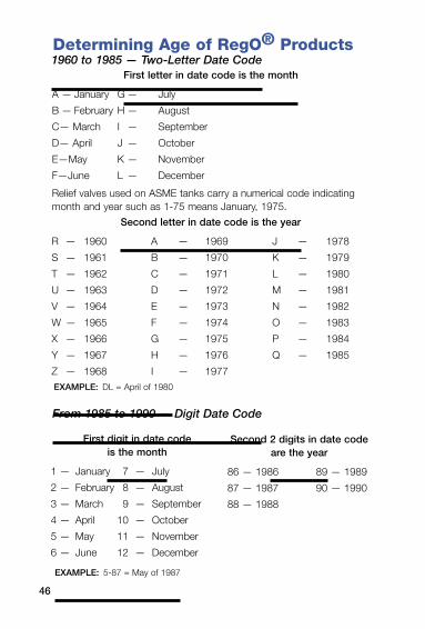
46
Determining Age of RegO® Products1960 to 1985 — Two-Letter Date Code
First letter in date code is the month
A — January G — July
B — February H — August
C— March I — September
D— April J — October
E—May K — November
F—June L — December
Relief valves used on ASME tanks carry a numerical code indicating month and year such as 1-75 means January, 1975.
Second letter in date code is the year
R — 1960 A — 1969 J — 1978
S — 1961 B — 1970 K — 1979
T — 1962 C — 1971 L — 1980
U — 1963 D — 1972 M — 1981
V — 1964 E — 1973 N — 1982
W — 1965 F — 1974 O — 1983
X — 1966 G — 1975 P — 1984
Y — 1967 H — 1976 Q — 1985
Z — 1968 I — 1977EXAMPLE: DL = April of 1980
From 1985 to 1990 — Digit Date Code
First digit in date code is the month
1 — January 7 — July
2 — February 8 — August
3 — March 9 — September
4 — April 10 — October
5 — May 11 — November
6 — June 12 — December
Second 2 digits in date code are the year
86 — 1986 89 — 1989
87 — 1987 90 — 1990
88 — 1988
EXAMPLE: 5-87 = May of 1987
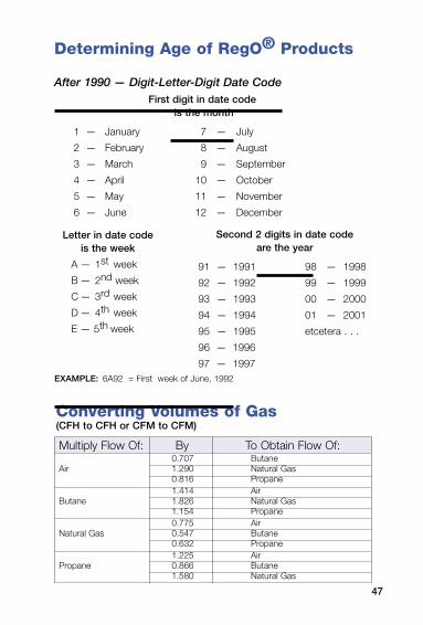
47
Converting Volumes of Gas(CFH to CFH or CFM to CFM)
0.707 ButaneAir 1.290 Natural Gas 0.816 Propane 1.414 AirButane 1.826 Natural Gas 1.154 Propane 0.775 AirNatural Gas 0.547 Butane 0.632 Propane 1.225 AirPropane 0.866 Butane 1.580 Natural Gas
Multiply Flow Of: By To Obtain Flow Of:
EXAMPLE: 6A92 = First week of June, 1992
After 1990 — Digit-Letter-Digit Date CodeFirst digit in date code
is the month
1 — January 7 — July
2 — February 8 — August
3 — March 9 — September
4 — April 10 — October
5 — May 11 — November
6 — June 12 — December
Letter in date code is the week
A — 1st week
B — 2nd week
C — 3rd week
D — 4th week
E — 5th week
Second 2 digits in date code are the year
91 — 1991 98 — 1998
92 — 1992 99 — 1999
93 — 1993 00 — 2000
94 — 1994 01 — 2001
95 — 1995 etcetera . . .
96 — 1996
97 — 1997
Determining Age of RegO® Products
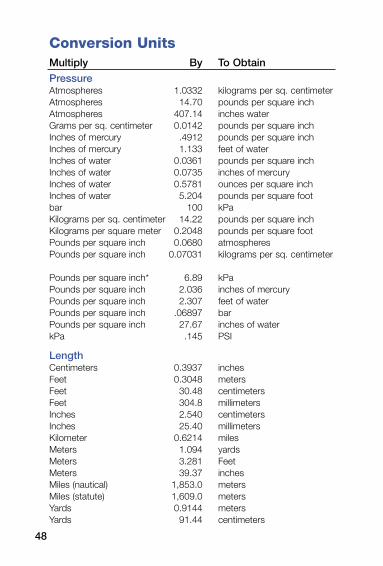
48
Conversion UnitsMultiply By To Obtain
PressureAtmospheres 1.0332 kilograms per sq. centimeterAtmospheres 14.70 pounds per square inchAtmospheres 407.14 inches waterGrams per sq. centimeter 0.0142 pounds per square inchInches of mercury .4912 pounds per square inchInches of mercury 1.133 feet of waterInches of water 0.0361 pounds per square inchInches of water 0.0735 inches of mercuryInches of water 0.5781 ounces per square inchInches of water 5.204 pounds per square footbar 100 kPaKilograms per sq. centimeter 14.22 pounds per square inchKilograms per square meter 0.2048 pounds per square footPounds per square inch 0.0680 atmospheresPounds per square inch 0.07031 kilograms per sq. centimeter
Pounds per square inch* 6.89 kPaPounds per square inch 2.036 inches of mercuryPounds per square inch 2.307 feet of waterPounds per square inch .06897 barPounds per square inch 27.67 inches of waterkPa .145 PSI
LengthCentimeters 0.3937 inchesFeet 0.3048 metersFeet 30.48 centimetersFeet 304.8 millimetersInches 2.540 centimetersInches 25.40 millimetersKilometer 0.6214 milesMeters 1.094 yardsMeters 3.281 FeetMeters 39.37 inchesMiles (nautical) 1,853.0 metersMiles (statute) 1,609.0 metersYards 0.9144 metersYards 91.44 centimeters
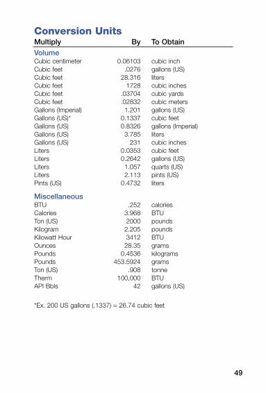
Conversion UnitsMultiply By To Obtain
VolumeCubic centimeter 0.06103 cubic inchCubic feet .0276 gallons (US)Cubic feet 28.316 litersCubic feet 1728 cubic inchesCubic feet .03704 cubic yardsCubic feet .02832 cubic metersGallons (Imperial) 1.201 gallons (US)Gallons (US)* 0.1337 cubic feetGallons (US) 0.8326 gallons (Imperial)Gallons (US) 3.785 litersGallons (US) 231 cubic inchesLiters 0.0353 cubic feetLiters 0.2642 gallons (US)Liters 1.057 quarts (US)Liters 2.113 pints (US)Pints (US) 0.4732 liters
MiscellaneousBTU .252 caloriesCalories 3.968 BTUTon (US) 2000 poundsKilogram 2.205 poundsKilowatt Hour 3412 BTUOunces 28.35 gramsPounds 0.4536 kilogramsPounds 453.5924 gramsTon (US) .908 tonneTherm 100,000 BTUAPI Bbls 42 gallons (US)
*Ex. 200 US gallons (.1337) = 26.74 cubic feet
49

Manual L-545 Copyright 1962 Revised 7/03 Printed in the USA 08-0703-0862
100 RegO Drive PO Box 247 Elon, NC 27244 USAPhone (336) 449-7707 Fax (336) 449-6594
• Distributor Information • Service Manuals• Application Guides • Product Literature• Product Updates • Technical Guides