Embed Size (px)
Citation preview
Milcom 2016 Track 2 - Networking Protocols and Performance
LOS Discovery for Highly Directional Full Duplex RFIFSO Transceivers
Suman Bhunia*, Mahmudur Khan t, Shamik Sengupta+ and Murat Yuksel§ *+Dept. of Computer Science and Engineering, University of Nevada, Reno, USA
t§Department of Electrical and Computer Engineering, University of Central Florida, Orlando, USA *[email protected], t [email protected], [email protected], §[email protected]
Abstract-Full duplex directional Radio Frequency (RF) I Free-Space-Optical (FSO) transceivers are envisioned to play a great role in future generation wireless networks. They provide
benefits in terms of better throughput, enhanced spectrum utilization and lower interference from unwanted sources. However, the stringent requirement of line-of-sight (LOS) communication makes it tough for a mobile node to maintain a link without apriori information about its neighbor's position. Hence, neighbor discovery takes a very crucial role in mobile ad hoc networks with directional transceivers. In this paper, we focus on neighbor discovery using full duplex directional transceivers. We consider two nodes that can discover each other by steering their transceivers with a randomly chosen angular speed and performing a simple three way handshaking protocol. We provide a theoretical analysis of the proposed neighbor discovery method. Additionally, we propose an algorithm where each node chooses its transceiver's angular speed and renews it if the neighbor is not discovered within an optimal time interval. We evaluate the algorithm via simulations and show its effectiveness under various scenarios.
Keywords-Full duplex, directional, RF, FSO, neighbor discovery, ad hoc, VANET, MANET
I. INTRODUCTION
In recent years, high gain directional antennas have attracted strong interest from the wireless community especially for ad hoc networks [1], [2], [3]. Directional antennas provide higher gain for signal reception and higher throughput than the traditional omnidirectional ones. Also, using directional antenna for signal reception reduces interference caused from unwanted directions as well as jamming. This directionality further improves spatial reuse. The directional antenna brings another advantage in terms of security as the transmission can not be intercepted or detected from a point that is not in the direction of the transmission beam. All these advantages of directional antennas are suitable for tactical ad hoc networks where multiple entities desire to transmit high bandwidth data streams simultaneously with a requirement of lower interference and reduced probability of being jammed or intercepted.
Alongside providing huge benefits, directional transceivers pose a unique challenge in maintaining links with neighbors. These transceivers require maintenance of line-of-sight (LOS) between neighbors particularly for small wavelength bands such as free-space-optical (FSO) (infrared or visible) and millimeter-wave bands. Due to the reduced field-of-view compared to the omni-directional case, a close-to-perfect alignment between the transmitter and the receiver may be required for the cOlmnunication link to work. So, a node has to steer its transceiver to face it towards the neighbor it wants to communicate with. Even if two nodes are within each others' communication range, they can not communicate if their
The authors acknowledge partial support from NSF award CNS #1346600, CNS #1422354, US ARO DURIP grant W911NF-14-1-0531, and the NASA NY Space Consortium.
978-1-5090-3781-0/16/$31.00 ©2016 IEEE
receiver
i ·
.. f ........ ·· .... ·· ... ... --... ..,./ receiver gain pattern
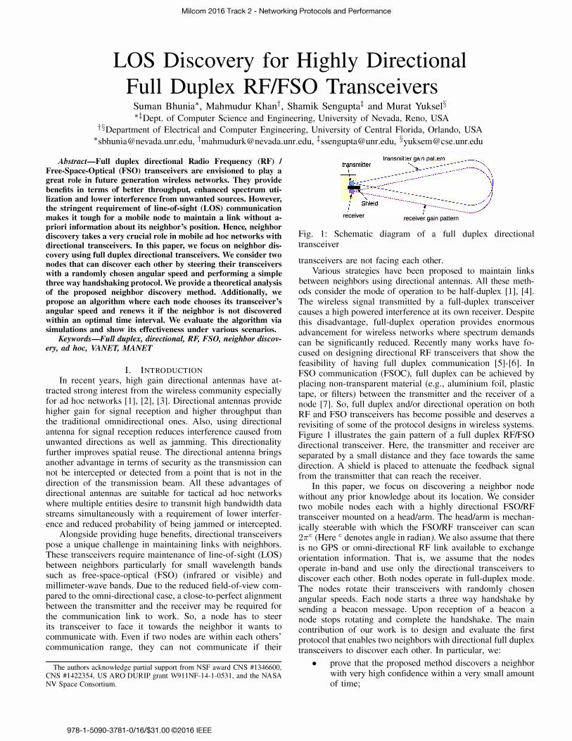
Fig. 1: Schematic diagram of a full duplex directional transceiver
transceivers are not facing each other. Various strategies have been proposed to maintain links
between neighbors using directional antennas. All these methods consider the mode of operation to be half-duplex [1], [4]. The wireless signal transmitted by a full-duplex transceiver causes a high powered interference at its own receiver. Despite this disadvantage, full-duplex operation provides enormous advancement for wireless networks where spectrum demands can be significantly reduced. Recently many works have focused on designing directional RF transceivers that show the feasibility of having full duplex communication [5]-[6]. In FSO communication (FSOC), full duplex can be achieved by placing non-transparent material (e.g., aluminium foil, plastic tape, or filters) between the transmitter and the receiver of a node [7]. So, full duplex and/or directional operation on both RF and FSO transceivers has become possible and deserves a revisiting of some of the protocol designs in wireless systems. Figure 1 illustrates the gain pattern of a full duplex RFIFSO directional transceiver. Here, the transmitter and receiver are separated by a small distance and they face towards the same direction. A shield is placed to attenuate the feedback signal from the transmitter that can reach the receiver.
In this paper, we focus on discovering a neighbor node without any prior knowledge about its location. We consider two mobile nodes each with a highly directional FSOIRF transceiver mounted on a head/arm. The head/arm is mechanically steerable with which the FSOIRF transceiver can scan 27rc (Here C denotes angle in radian). We also assume that there is no GPS or omni-directional RF link available to exchange orientation information. That is, we assume that the nodes operate in-band and use only the directional transceivers to discover each other. Both nodes operate in full-duplex mode. The nodes rotate their transceivers with randomly chosen angular speeds. Each node starts a three way handshake by sending a beacon message. Upon reception of a beacon a node stops rotating and complete the handshake. The main contribution of our work is to design and evaluate the first protocol that enables two neighbors with directional full duplex transceivers to discover each other. In particular, we:
• prove that the proposed method discovers a neighbor with very high confidence within a very small amount of time;
Milcom 2016 Track 2 - Networking Protocols and Performance
• propose a protocol where the nodes choose angular speed randomly and reinstates the speed after a threshold time; and
• show through simulation that the proposed mechanism works well for both stationary and mobile ad hoc networks.
The simulation results confirm that, with the proposed protocol, the average discovery time can be as small as 68 for mobile nodes with divergence angle of 7r 136c and 1.228 for mobile nodes with divergence angle of 7r 1I5c.
The rest of the paper is organized as follows: Section II surveys the relevant background on directional transmission and neighbor discovery. The proposed methodology, theoretical analysis and the algorithms are described in Section III. Section IV illustrates the simulation scenarios and discusses the results. Finally, Section V concludes the paper.
II. BACKGROUND
In this section, we first discuss the motivation for directional transmission using both FSO and RF cOlmnunications. Then, we present the already proposed neighbor discovery protocols for directional transmission and their shortcomings.
A. Directional Transmission In [8], a new technology involving FSOC between un
manned aircrafts (e.g., Aquila - UAV developed by Facebook) is proposed, that will help connect areas of the world that currently do not have Internet infrastructure. A method for establishing and maintaining an FSO link among nearby balloons with the aid of GPS, RF, camera, and communication with a ground station is presented in [9].
Unlike these out-of-band techniques, in [10], we proposed an in-band method that deals with the problem of maintenance of LOS alignment between two autonomous mobile nodes moving on 2D plane with mechanical steering of FSO transceivers. For RF-challenged environments, such in-band techniques that only use the FSO link itself with no dependence on RF-based links are necessary.
B. Directional Neighbor Discovery Neighbor discovery for directional RF has been well ex
plored. Choudhury et al. [I], [4] have designed a MAC protocol for ad hoc networks with directional transmitter and omnidirectional receivers. They suggested that nodes can transmit their positional information with omni-directional transmitters in order for all nodes to be aware of their neighbors' positions. Ramanathan et al. [ll] presented UDAAN, the first full system deployment of ad hoc network utilizing directional antennas. It uses heartbeat messages to exchange the position information and uses GPS clock cycle synchronization for neighbor discovery. This prototype uses omni-directional antennas for establishing the connection with new neighbors.
Zhang et al. [3], [12] proposed two algorithms for neighbor discovery with directional RF communication. The authors considered that the nodes are synchronized and use synchronized slots to transmit neighbor discovery requests. Although [3] provides a good analysis on number of slots required to complete the neighbor discovery, the consideration of all nodes using synchronous slots is not very practical. Pei et al. [13] proposed another neighbor discovery protocol for directional MANETs based on synchronous search.
lakllari et al. [14] is the only earlier work we found that deals with directional transmitter and receiver. It proposed a
polling based MAC protocol for MANETs where all nodes are synchronized in terms of the polling slots. It allocates slots for discovering new neighbors when all nodes in a MANET points to random direction and advertise for neighbor discovery. It also provides a framework to compute neighbor discovery time. We assume no synchronization among nodes.
Most of the proposed neighbor discovery algorithms consider either omni-directional transmission or omni-directional reception, and immobile nodes. Also, some works consider availability of GPS and some consider that all nodes have prior information about neighbors' movement. To the best of our knowledge, this is the first work on directional neighbor discovery protocol with full-duplex mode of conununication and without any out-of-band support like GPS or an extra communication channel.
III. METHODOLOGY
A. Assumptions We assume the followings for our proposed model:
1) Node IDs: Each node is assigned with an unique identifier (such as MAC address).
2) Full Duplex: The cOlmnunication between the nodes is full-duplex.
3) Mobility: The nodes can move autonomously and are within transmission range of each other in a 2D plane.
4) Frequency: The discovery phase use in-band communication and does not require a separate control channel.
5) Directional: Both the transmitter and the receiver of a node face towards the same direction and rotate together as shown in Figure 1. The receiver can receive signal from a neighbor that is within its main beam and the transmission beam of the neighbor must face towards the receiver. As a node's own transmitter and receiver face the same direction, its own transmission will not cause any interference to its receiver.
6) Gain: We consider that the nodes use highly directional transceivers with fixed beam width. We consider very high transmission gain in the direction of the main lobe and zero gain outside in the direction that is outside of main lobe.
7) Transceiver rotation: The nodes can rotate their transceivers using mechanically steerable heads. While performing neighbor discovery, both nodes rotate in the same manner (both clockwise/both counterclockwise).
8) Asynchronous algorithm: The nodes run the proposed algorithm in a distributed manner without any synchronization mechanism.
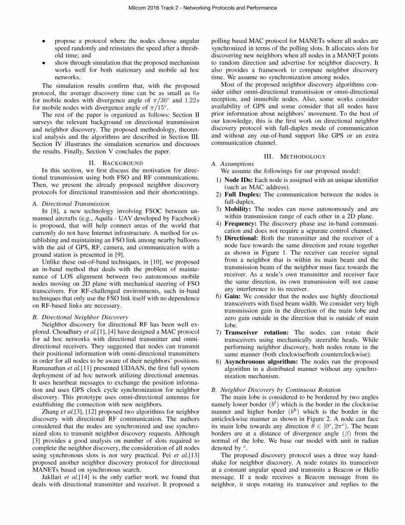
B. Neighbor Discovery by Continuous Rotation The main lobe is considered to be bordered by two angles
namely lower border (bl) which is the border in the clockwise manner and higher border (bh) which is the border in the anticlockwise manner as shown in Figure 2. A node can face its main lobe towards any direction e E [OC,27rC). The beam borders are at a distance of divergence angle (f3) from the normal of the lobe. We base our model with unit in radian denoted by c.
The proposed discovery protocol uses a three way handshake for neighbor discovery. A node rotates its transceiver at a constant angular speed and transmits a Beacon or Hello message. If a node receives a Beacon message from its neighbor, it stops rotating its transceiver and replies to the
Milcom 2016 Track 2 - Networking Protocols and Performance
Symbol j3
Wx T
fix bl b� '"
TABLE I: List of used symbols
Description divergence angle of a transceiver chosen angular speed of transceiver of node x minimum time required to complete three way handshake initial angle at which x directs its transceiver beam border in clockwise direction beam border in anticlockwise direction chosen statistical confidence
Ta time required to have", confidence for neighbor discovery
a'
bl : y:
I · ·
time=tt
· ' time=to••• •• -.,/
Fig. 2: Schema for neighbor discovery
a
neighbor with a B-ACK message. The node receiving the BACK message also stops rotating its transceiver and replies with an ACK message to the neighbor denoting completion of neighbor discovery. Upon completion of neighbor discovery, the nodes move to link maintenance phase as proposed in our earlier work [10].
C. Theoretical analysis In this section we investigate the probability of neighbor
discovery within a bounded time. The used symbols are listed in Table I. Let us consider that the total time required to send Beacon, receive B-ACK and then to send ACK is T. It incorporates the transmission (ttran), propagation (tprop) and processing (tproe) delays at both ends. T can be calculated as:
ttran T
Beacon size + B-ACK size + ACK size data rate
ttran + 3 x tprop + 2 x tproe (1)
Now, tprop will vary with distance but we can consider a maximum propagation delay as the time required for the signal to propagate within transmission range which is in the order of nano seconds. tproc can also vary depending on the hardware and the work load on the processor at that moment.
Theorem 1: If the angular speed of either of the transceivers is greater than 2(3/ T, neighbors can not be discovered.
Proof Let us consider the case of two stationary nodes x and y as depicted in Figure 2. At time t = to, x is facing its transceiver at an angle of ex and y is facing its transceiver
at ey. Now, we need to find out when x and y would be able to discover each other. It is obvious that the nodes can discover each other if at a certain time x and y both face their transceivers towards each other for at least T amount of time. As it takes x's beam 2(3/wx seconds to scan across y, the maximum angular speed for x should not be more than 2(3/ T so that the transceivers of x and y can hear each other for at least T amount of time. As shown in Figure 2, lower beam border of x, b�, will reach aa' in (ex - (3)/wx seconds. Let's say l� and h� denotes the time when b� and b� respectively reaches the LOS axis aa'. Then:
In x
(ex - (3) + 2mf (2) n E [0,1,2, . . . . J
Wx (ex + (3) + 2mf
n E [0,1,2, . . . . J (3) Wx
Similarly, for y, the beam borders will reach aa' at: (ey - (3) + (2m - 1)7f
Wy (ey + (3) + (2m - 1)7f
Wy ,
m E [0,1,2, . . . . J (4)
m E [0,1,2, . . . . J (5)
Thus, the discovery can be completed if for any value of nand m, the following condition is satisfied
min(h�, h;;') - max(l�,l;;') � T (6) For successful neighbor discovery the main beam of a node
has to face its neighbor for at least T time, i.e. V n h� -l� � T. Replacing these values from (2) and (3) , we can derive that 2(3/wx � T. Thus Wx � 2(3/T. Similarly, we can prove that Wy � 2(3/T. Thus, they can not discover each other if any one of them has a angular speed greater than 2(3/T. •
Theorem 2: If nodes x and y rotate their transceivers with same angular speed w, then they can be discovered iff
ex - 2(3 + WT ± 7f < ey < ex + 2(3 - WT ± 7f (7) Proof Let the orientation of the transceivers of nodes x
and y with respect to x-axis be ex and ey respectively. As shown in Figure 2, e; = ex - (3, e� = ex + (3, et = ey - (3 and e; = ey + (3. Case I: ex + 7f < ey. Then, b� will reach aa' before bt does. Here, e� will reach aa' at t = (ex - (3)/w seconds. e� will reach aa' at t = (ex + (3) / W seconds. Then, e� has to reach aa'
before t = (ex+(3)/w - T. SO, (ey-(3)/w < �ex+(3)/W-T+7f or, ey < ex + 2(3 - WT + 7f. Case II: ex + 7f > ey. Then bt will be aligned with aa' before bt. Then, e; must leave aa' only after (ex - (3)/w + T, which yields, ey > ex - 2(3 + WT + 7f. Thus, the condition for successful neighbor discovery is, ex - 2(3 + WT + 7f < ey < ex + 2(3 - WT + 7f. Similarly, we can prove that, ex - 2(3 + WT - 7f < ey < ex + 2(3 - WT - 7f. Consolidating these two equations will yield (7). •
Lemma 1: The probability that the nodes discover each other increases as the tlcm increases, where tlem is the Least Common Multiple (LCM) of the time required for each of the transceivers' full rotation.
Proof The transceivers of nodes x and y will complete a circle in 27f /wx and 27f /wy seconds respectively. Both nodes will come to same formation after every LCM(27f/wx,27f/wy) seconds. So, we can say that the probability of discovery Pd is equal to the probability of discovery within tlem, Plcm. Within

Milcom 2016 Track 2 - Networking Protocols and Performance
this time, b� will touch aa' nx times where, l tlcm J nx = 27r /wx (8)
where, tlcm = LCM(27r/wx,27r/wy). Let us assume that at time tl, b� touches aa'. If b� can touch aa' within :: -7 time, then it can receive the beacon and complete the handshake. So, for a successful discovery b� can be at most at 7r+Wy(� -7). Thus, we can write probability of discovery in the first rotation Po as
W (2(3 - 7) Y Wx Po = --"'----27r (9)
Since, within tlcm time, the transceiver will rotate nx times, it will have as many chances to complete the discovery. So, probability of discover in tlcm can be written as:
Plcm = 1 - (1 - po tx (10)
Combining (8) , (9) and (10) , it is clear that if tlcm is high then the probability of detection is high. •
Corollary 1: Probability of discovery within time t can be approximated as:
- Lt/tlc=J + (1 ) Pt - Plcm -Plcm Pt' (11)
Proof As b� will cross the same position every tlcm, we can say that the probability of discovery within a time that is a multiple of the tlcm will be same as Plcm. Let us assume, after spending tlcm x It/tlcmJ time, node x will have t' time left for discovery. The number of full rotations of x within t' can be derived as:
nt' = l27r�WX J (12)
where, t' = t -tlcm X It/tlcmJ. Then, probability of discovery within nt' rotation,
Pn" = 1 - (1 - po)n" (13) Let us assume, after nt', there is til time left. Similar to
(9) , we can say that b� can touch the aa' line anytime between o and 27r /wx - 7. Thus, the probability of discovery within a time til where til is less time than a full rotation, can be derived as:
til Pt" = Po x --- ; 27r/wx
where, til = t' - 27r X nt'. Wx probability of discovery in t' as:
7 :s; t' :s; 27r /wx (14)
Then we can calculate the
Pt' = Pn" + Pt" (15)
Since, probability of discovery in first n tlcm time is same as probability of discovery in first tlcm, we can write, probability of discovery within time t can be written as (11) .
•
D. Rotational Speed Reset Time A node randomly chooses its transceiver's rotational speed
without any knowledge about its neighbor's location or rotational speed. Now, for some combinations of the rotational speeds of a pair of neighboring nodes, the discovery time can be very high (for an example if they choose equal speed). Therefore, if a node does not discover its neighbor within a given time period it resets it's rotational speed.
Let Pt(Wmin, WmaX) be the probability of discovery within time t where Wmin and Wmax are the lower and the upper limit of choosing the angular speed Wx and wy. Since having a strict range (0,2(3/7) for choosing a rotational speed may not be optimal, the range is chosen as [Wmin, WmaX] at the starting of the neighbor discovery phase. Let a E (0, 1) be a statistical significance for neighbor discovery (i.e., the probability of neighbor not being discovered is a). Then under the base model assumption, we can find out the time required, To., to ensure the probability of neighbor discovery of at least 1 -a.
(16)
s.t. Pt(Wmin, WmaX) 2 1 - a Now, for a given a, the optimal values for To. can be
observed as:
Wm,in ,W'max s.t. Wmin E [0,2(3/7)
wmax E (0,2(3/7] Wmin < Wmax
Now, from the optimal value of Wmin and Wmax are:
opt wmin
Wopt max Wrnin
W'max
(17)
(18)
(19)
The mathematical model for obtaining J1D( discovery) within a given time, resembles a continuous space markov chain as the initial position for the nodes are in [0, 27r). We observed the effect of Wmin, Wmax on To. through rigorous simulations. The simulation results are discussed in Section IV-A3.
E. Randomized Neighbor Discovery Algorithm 1 presents the steps of neighbor discovery
whereas Figure 3 illustrates the state diagram of a node. The main idea behind this algorithm is to rotate the transceivers in a steady speed w and if the neighbor is not discovered within a given amount of time then W is changed.
As the first step, a node chooses an optimal confidence level, a, given (3 and 7. The optimal value of a is observed through simulation described in Section IV-B. The node uses (17) to determine optimal values for Wmin and Wmax and randomly selects an angular speed from (Wmin, WmaX). At this point the node can forecast that within To. seconds the neighbor can be discovered with a probability greater than 1 - a. A timeout value is set as the current time with addition to To.. Now, the node starts rotating its transceiver clockwise and sends beacon messages. Since we are considering full duplex communication, the node can receive beacon from the neighbor while transmitting beacons. If a beacon is successfully received from the neighbor node, it stops rotating its transceiver and sends an B-ACK message. Similarly, if B-ACK is received from a neighbor, it stops rotating and sends a ACK message to denote completion of the three way handshaking. The node transitions to link maintenance phase after successful completion of the handshaking. If neither B-ACK nor a beacon is received, the node keeps transmitting beacon messages while maintaining the angular speed. If the handshaking procedure is not complete during the timeout interval, the node changes to a new rotational speed for the transceivers. This new rotational

Milcom 2016 Track 2 - Networking Protocols and Performance
eacon recel I send B·ACK, stop rotating
Beacon sent
I start rotation with w _�==-�=:.=-
B·ACK not received
Tatimeout
ACK received
B·AC received I stop rotating
sen ACK
Fig. 3: State transition diagram
speed is again randomly picked from (Wmin, wmax) .
Algorithm 1: Algorithm for neighbor discovery 1 Choose optimal confidence level 0:
2 Determine Wmin and Wmax from the optimal point 3 Choose an angular speed W E (Wmin, wmax) 4 Timeout f- current_time + Tex 5 Start rotating the transceiver with W
6 Send the Beacon 7 if Beacon received from other node then 8 L stop rotating and send B-ACK
9 else if ACK received from neighbor then 10 l stop rotating send ACK 11 Start link maintenance phase 12 else if currenCtime > Timeout then 13 L Goto step 3
14 else 15 L Goto step 6
IV. SIMUL ATIONS AND RESULTS
We performed simulations using Python and MATLAB to analyze the effectiveness of the proposed neighbor discovery algorithm. We considered both stationary (both nodes stationary) and mobile scenarios. We assumed the nodes to be in the transmission range (100m) of each other. Different divergence angles (7r/60c,7r/36c,7r/24c,7r/15C) were considered for the simulations.
We consider the MAC layer frame structure of the nodes to be similar to that of WiFi. A frame consists of preamble, header, payload (data) and CRC field. For the three handshaking messages (Beacon, B-ACK and ACK) of the neighbor discovery protocol the payload size is zero. In this case, frame size is considered to be 38 bytes long. Considering 1 Mbps data rate, the transmission time for one packet is 304 J.Ls. Since, propagation delay is negligible compared to other delays, the value of 7 can be determined from (1) as: 7 = 3 x 304 + 2 x 100 = 1112 J.L s.
A. Both nodes stationary 1) Obtaining statistical significance 0:: As the first step,
we run a pilot simulation to see if neighbor discovery can be achieved within a short time with high confidence. Note that, here the nodes do not apply periodic reset of the angular speed. In every simulation, the nodes are initialized with their initial transceiver orientation randomly chosen from [0, 27r)c. Also, each node randomly chooses its rotational speed from [0,2,8/7) cis. The simulation monitors when the two nodes
Fig. 5: Depiction of optimal Tex for ,8 = 7r /60
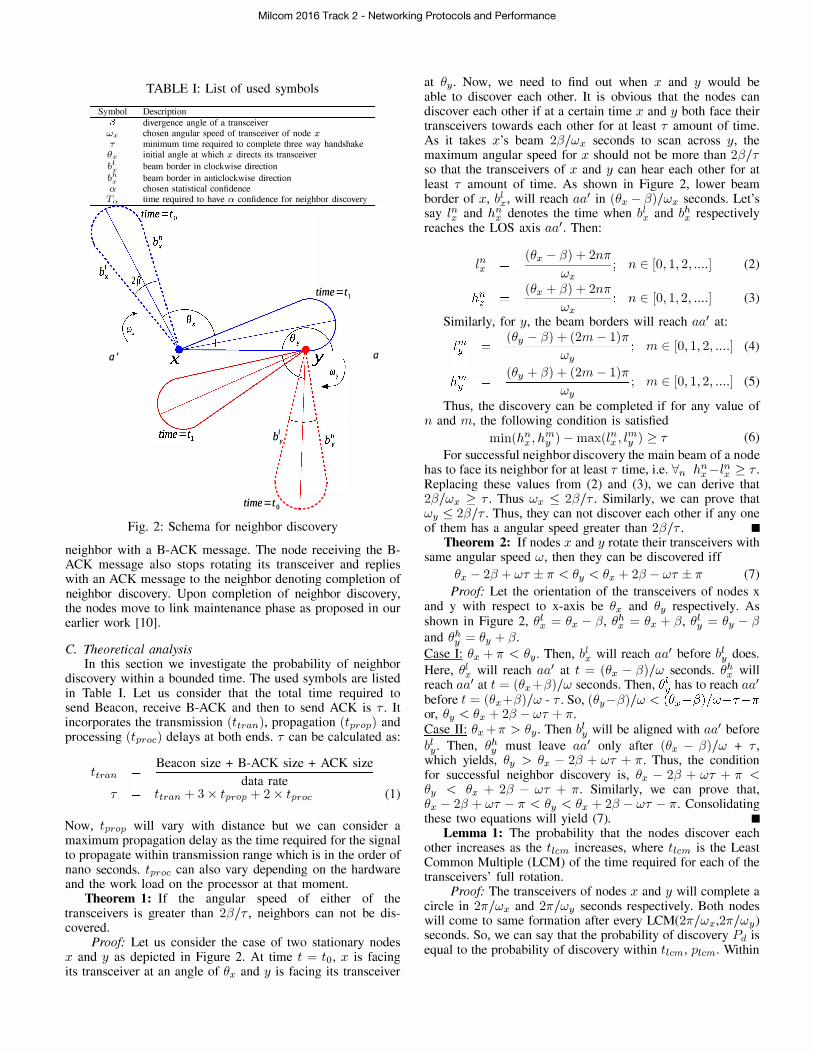
discover each other. This simulation is repeated 1,000,000 times to obtain reliable results. Here, the packet processing time is considered to be 100 J.LS. Figure 4a plots the probability of neighbor discovery within a given time. Here, xaxis represents time spent in seconds and y-axis represents the cumulative probability of neighbor discovery within time t. Four divergence angles of transceivers are being considered here. It is clear from the figure that the higher the divergence angle, the lower the amount of time is required for neighbor discovery. Note that, for some cases the neighbor discovery might never happen (for example if both the nodes choose same angular speed). In this case, the time taken for discovery will be 00. Thus, the cumulative distribution function will never reach L We can see that the neighbor can be discovered with a probability > 0.9 within a short period of time. However, to obtain a discovery probability of 0.95, a node needs significantly longer period of time. This necessitates the periodic reset of the angular speed.
2) Effect of packet processing delay: Figure 4b depicts the effect of packet processing delay on the performance of the neighbor discovery protocoL Here, x-axis represents the processing delay in J.LS and y-axis represents the rotational speed reset time that is required to obtain 0.1 confidence (To.d, i.e. neighbor discovery probability of 0.9. For each set of parameters the simulation is repeated 1,000,000 times to obtain reliable results. At each simulation a node chooses an angular speed, W E (0,2,8/7), where 7 is calculated according to (1) . We can clearly see that for a very narrow beam transceiver (,8 = 7r /60), an increase in the processing time significantly increases the reset time; thus, increasing the neighbor discovery time. For transceivers with wider beam (,8 = 7r /36c or 7r /24c or 7r /15C), the increase in reset time as the processing delay increases is less significant
3) Choosing optimal Wmin and Wmax: Figure 4c illustrates the effect of choosing different range of the angular speed. Here the results are plotted for two different values of divergent angle and three different ranges of the angular speed. It is very clear from the picture that choosing a hard range of (0,2,8/7) does not provide optimal result as probability of discover� is lower in this case than that for the range of (0.252;,0.75 f).
In this section, the simulation is intended to obtain optimal values of Wmin and Wmax as a function of ,8, 7 and 0:. The processing time is 100 J.Ls and 7 is calculated as in (1) .
Milcom 2016 Track 2 - Networking Protocols and Performance
(a) Cumulative probability of dis- (b) Time required to obtain 90% (c) Example of the effect of differ- (d) Average discovery time. Two covery within a time t probability of discovery ent Wmin and Wmax mobile nodes with f3 = 7f /36.
Fig. 4: Simulation Results
TABLE II: Tg,pt in seconds for different a and (3 TopI
a f3-1r/60 /3-1r/36Q f3-1r/24 f3-1r/15 0.1 19.0 7.0 3.0 2.0
0.09 20.0 8.0 4.0 2.0 0.08 22.0 8.0 4.0 2.0 0.07 25.0 9.0 4.0 2.0 0.06 29.0 10.0 5.0 2.0 0.05 33.0 12.0 6.0 3.0 0.04 40.0 15.0 7.0 3.0 0.03 51.0 20.0 9.0 4.0 0.02 74.0 28.0 13.0 5.0 0.01 100.0 51.0 23.0 10.0
SimulatIOns are performed with dtfterent values of a. figure 5 presents the relationship between the range of angular speeds (Wmin, wmax) and the time required for neighbor discovery with probability of 0.95 or a = 0.05. Note that, in this plot both Wmin and Wmax are chosen from [O,2(3/T] . The results demonstrate that Ta. is a concave function with respect to Wmin and Wmax· We found that Wmin = 0.25 X 2(3/T and Wmax = 0.75 X 2(3/T provides the optimal point (Tg,Pt). Table II provides the obtained Tg,pt for different values of a
and (3.
B. Both nodes mobile Here, we consider both nodes to be mobile. The nodes'
initial positions, speed (between 0-2.5m/s) and transceiver orientation are randomly chosen. The divergence angle (3 is chosen as 7f /36. The simulator assumes a packet processing delay of 100 J.Ls. The transceivers use Algorithm 1 for discovering the neighbor. Note that Tg,pt is chosen from Table II and used as the rotational speed reset time. The simulation results are plotted in Figure 4d. Here x-axis denotes the chosen confidence level a and y-axis denotes the average time required to complete neighbor discovery. The figure also depicts 95% confidence interval of the time required for neighbor discovery. It can be observed from the figure that at a = 0.06, the average neighbor discovery time is the lowest. So, for (3 = 7f /36 and processing delay of 100 J.LS, the optimal a = 0.06.
V. CONCLUSION
We proposed a novel approach for neighbor discovery in both stationary and mobile scenarios. We consider two nodes, each equipped with a mechanically steerable head/arm on which a highly directional FSO or RF transceiver is mounted. The nodes rotate the transceivers and send search signals to discover the neighbor. We proposed a method for finding optimal rotational speeds for the node's heads mounted with transceivers. Through extensive simulations we showed that the nodes can discover each other within reasonable period of time.
We plan to perform real test-bed experiments to evaluate the effectiveness of the proposed method. Another possible line of future work is to consider a ground-to-air link or consider LOS discovery between two airborne mobile nodes using directional FSO or RF transceivers.
REFERENCES
[I] R. R. Choudhury. X. Yang. R. Ramanathan. and N. H. Vaidya, "Using directional antennas for medium access control in ad hoc networks," in International conference on Mobile computing and networking, pp. 59-70, ACM, 2002.
[2] S. Bhunia, Y. Behzadan, P. A. Regis, and S. Sengupta, "Adaptive beam nuUing in multihop ad hoc networks against a jammer in motion," Computer Networks, pp. -, 2016.
[3] Z. Zhang and B. Li, "Neighbor discovery in mobile ad hoc selfconfiguring networks with directional antennas: algorithms and comparisons," Wireless Communications, IEEE Transactions on, vol. 7, no. 5, pp. 1540-1549, 2008.
[4] R. R. Choudhury, X. Yang, R. Ramanathan, and N. H. Vaidya, "On designing mac protocols for wireless networks using directional antennas," IEEE Transactions on Mobile Computing, vol. 5, no. 5, 2006.
[5] E. Everett, M. Duarte, C. Dick, and A. Sabharwal, "Empowering fullduplex wireless communication by exploiting directional diversity," in ASILOMAR, pp. 2002-2006, IEEE, 2011.
[6] E. Everett, A. Sahai, and A. Sabharwal, "Passive self-interference suppression for full-duplex infrastructure nodes," Wireless Communi
cations, IEEE Transactions on, vol. 13, no. 2, pp. 680-694, 2014.
[7] A. Sevincer, M. Bilgi, and M. Yuksel, "Automatic realignment with electronic steering of free-space-optical transceivers in manets: A proofof-concept prototype," Ad Hoc Networks, vol. 11, no. 1, 2013.
[8] "Facebook laser communication." https://www.facebook.comlzuck/vide -os/l 01 0227495 17253011.
[9] R. W. DeVaul, E. Teller, C. L. Biffle, and J. Weaver, "Establishing optical-communication lock with nearby balloon," Jan. 9 2012. US Patent App. 13/346,645.
[10] M. Khan and M. Yuksel, "Maintaining a free-space-optical communication link between two autonomous mobiles," in IEEE WCNC, pp. 3154-3159, IEEE, 2014.
[II] R. Ramanathan, J. Redi, C. Santivanez, D. Wiggins, and S. Polit, "Ad hoc networking with directional antennas: a complete system solution," IEEE JSAC, vol. 23, no. 3, pp. 496-506, 2005.
[12] Z. Zhang, "Performance of neighbor discovery algorithms in mobile ad hoc self-configuring networks with directional antennas;' in IEEE
MILCOM 2005, pp. 3162-3168, 2005.
[13] G. Pei, M. M. Albuquerque, J. H. Kim, D. P. Nast, and P. R. Norris, "A neighbor discovery protocol for directional antenna networks," in IEEE
MILCOM, pp. 487-492, IEEE, 2005.
[14] G. Jakllari, W. Luo, and S. Y. Krishnamurthy, "An integrated neighbor discovery and mac protocol for ad hoc networks using directional antennas," Wireless Communications, IEEE Transactions on, vol. 6, no. 3, pp. 1114-1024, 2007.