Embed Size (px)
Citation preview
1Wireless Radio Modem User’s ManualRev:B1.2
WarrantyAll products manufactured by ICP DAS are warranted
against defective materials for a period of one year from the dateof delivery to the original purchaser.Warning
ICP DAS assume no liability for damages consequent tothe use of this product. ICP DAS reserves the right to change thismanual at any time without notice. The information furnished byICP DAS is believed to be accurate and reliable. However, no re-sponsibility is assumed by ICP DAS for its use, nor for any in-fringements of patents or other rights of third parties resulting fromits use.Copyright
Copyright 1999 by ICP DAS. All rights are reserved.Trademark
The names used for identification only maybe registeredtrademarks of their respective companies.
Wireless Radio ModemUser’s Manual
Date:2001-11
2 Wireless Radio Modem User’s Manual Rev:B1.2
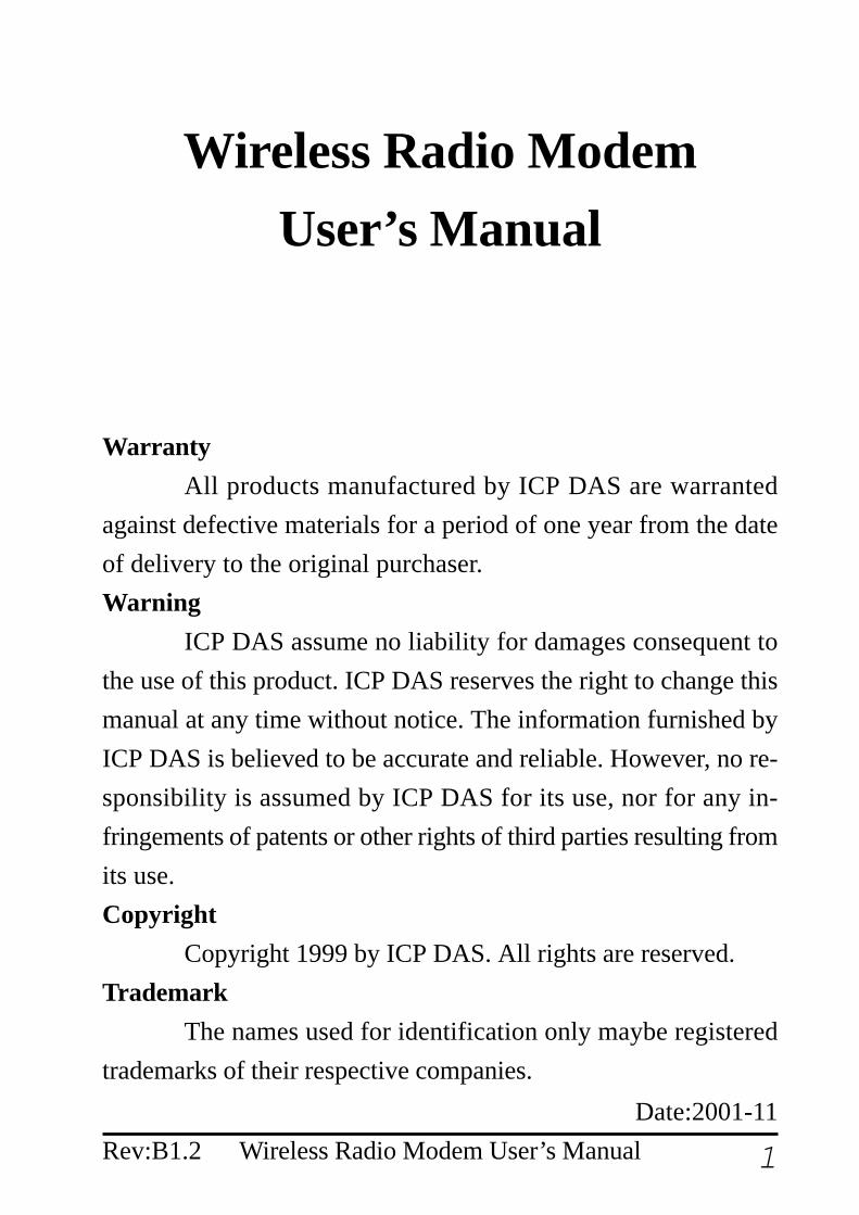
Table of Contents
1. Introduction.....................................................41.1 Block Diagram ...........................................41.2 Specifications .............................................5
1.2.1 SST-900EXT Wireless Radio Modem .......... 51.2.2 SST-2400EXT Wireless Radio Modem ........ 61.2.3 SST-900A External 900MHz Antenna ......... 71.2.4 SST-2400A-3 External 2.4GHz Antenna ..... 71.2.5 SST-2400A-12 External 2.4GHz Antenna ... 81.2.6 SST-2400A-13 External 2.4GHz Antenna ... 8
1.3 Pin Assignment ..........................................91.4 Jumper Setting .........................................101.5 Wire Connection ...................................... 111.6 Dimension ................................................14
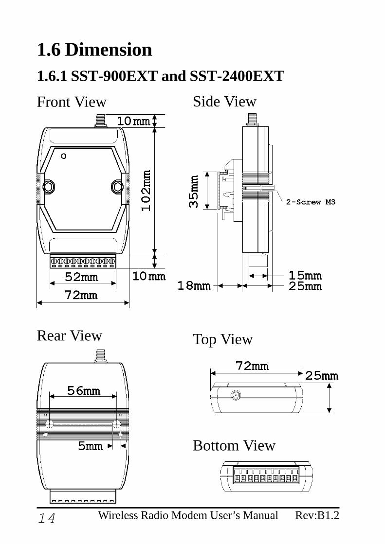
1.6.1 SST-900EXT and SST-2400EXT ............... 141.6.2 DIN-RAIL Mounting .................................. 151.6.4 Pannel Mounting......................................... 16
2 Configuration .................................................172.1 Full-duplex and Half-duplex ....................172.2 Synchronous and Asynchronous ..............182.3 Configuration Select ................................192.4 Operation Mode 1 ....................................20

3Wireless Radio Modem User’s ManualRev:B1.2
2.5 Operation Mode 2 ....................................212.6 Operation Mode 3 ....................................22
3 Application......................................................233.1 Peer-to-Peer Communication...................233.2 Asynchronous Connection .......................243.3 Multiple PCs Communication..................253.4 Connect I-7000 Modules .........................263.5 Communication Bridge............................273.6 Network Communication .........................28
4 Wireless Radio Modem User’s Manual Rev:B1.2
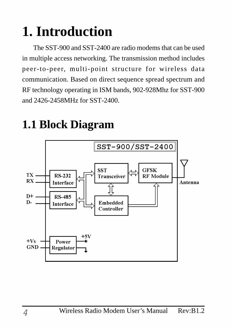
1. IntroductionThe SST-900 and SST-2400 are radio modems that can be used
in multiple access networking. The transmission method includespeer-to-peer, multi-point structure for wireless datacommunication. Based on direct sequence spread spectrum andRF technology operating in ISM bands, 902-928Mhz for SST-900and 2426-2458MHz for SST-2400.
1.1 Block Diagram

5Wireless Radio Modem User’s ManualRev:B1.2
1.2 Specifications1.2.1 SST-900EXT Wireless Radio ModemRF Communication TransceiverFrequency Band : 909 to 924 MHz for SST-900Channel Spacing : 2.048 MHz (8 channels jumper select)Output Power : 20±2 dBmModulation : GMSKTime Division DuplexingTransimition Range : Max 300MSST TransceiverDirect Sequency Spread SpectrumNon-Overlapping Channels : 8 channels, jumper select (only forfull-duplex operation)Full-duplex or Half-duplex, jumper selectSynchronization or Asynchronization, jumper selectSerial Communication InterfaceRS-232(TxD, RxD, GND) and RS-485(D+, D-), jumper selectBaudrate : 600bps to 57600bps, jumper selectEnvironmentOperating Temperature : 0°C to 50°CStorage Temperature : -30°C to 70°CPower SupplyInput : +10 to +30VDC, unregulatedConsumption : 1.5W

6 Wireless Radio Modem User’s Manual Rev:B1.2
1.2.2 SST-2400EXT Wireless Radio ModemRF Communication TransceiverFrequency Band : 2426 to 2458 MHzChannel Spacing : 2.048 MHz (8 channels jumper select)Output Power : 20±2 dBmModulation : GMSKTime Division DuplexingTransimition Range : Max 300M with bundled antenna
Max 1000M with SST-2400A-3 antennaMax 5000M with SST-2400A-12 antennaMax 5000M with SST-2400A-13 antenna
SST TransceiverDirect Sequency Spread SpectrumNon-Overlapping Channels : 8 channels, jumper select (only forfull-duplex operation)Full-duplex or Half-duplex, jumper selectSynchronization or Asynchronization, jumper selectSerial Communication InterfaceRS-232(TxD, RxD, GND) and RS-485(D+, D-), jumper selectBaudrate : 600bps to 57600bps, jumper selectEnvironmentOperating Temperature : 0°C to 50°CStorage Temperature : -30°C to 70°CPower SupplyInput : +10 to +30VDC, unregulatedConsumption : 1.5W

7Wireless Radio Modem User’s ManualRev:B1.2
1.2.3 SST-900A External 900MHz AntennaExternal antenna for SST-900EXTMaximum Distance : 1000MWeight : 1000gAntenna Gain : 5dBCable : RG58C/U, 4M
1.2.4 SST-2400A-3 External 2.4GHz AntennaExternal antenna for SST-2400Maximum Distance : 1000MWeight : 150gAntenna Gain : 3dBCable : RG58A/U, 1M
8 Wireless Radio Modem User’s Manual Rev:B1.2
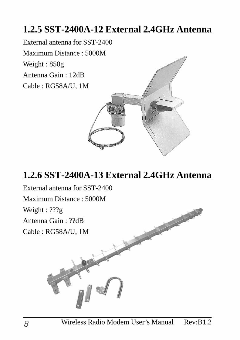
1.2.5 SST-2400A-12 External 2.4GHz AntennaExternal antenna for SST-2400Maximum Distance : 5000MWeight : 850gAntenna Gain : 12dBCable : RG58A/U, 1M
1.2.6 SST-2400A-13 External 2.4GHz AntennaExternal antenna for SST-2400Maximum Distance : 5000MWeight : ???gAntenna Gain : ??dBCable : RG58A/U, 1M

9Wireless Radio Modem User’s ManualRev:B1.2
1.3 Pin Assignment
DSR Reserved signal of diagnosticRX Receive of RS-232TX Transimit of RS-232GND Ground of RS-232(Y)D+ Data+ of RS-485(G)D- Data- of RS-485(R)+Vs +10 to +30V DC power supply input(B)GND Ground of power supply input
10 Wireless Radio Modem User’s Manual Rev:B1.2
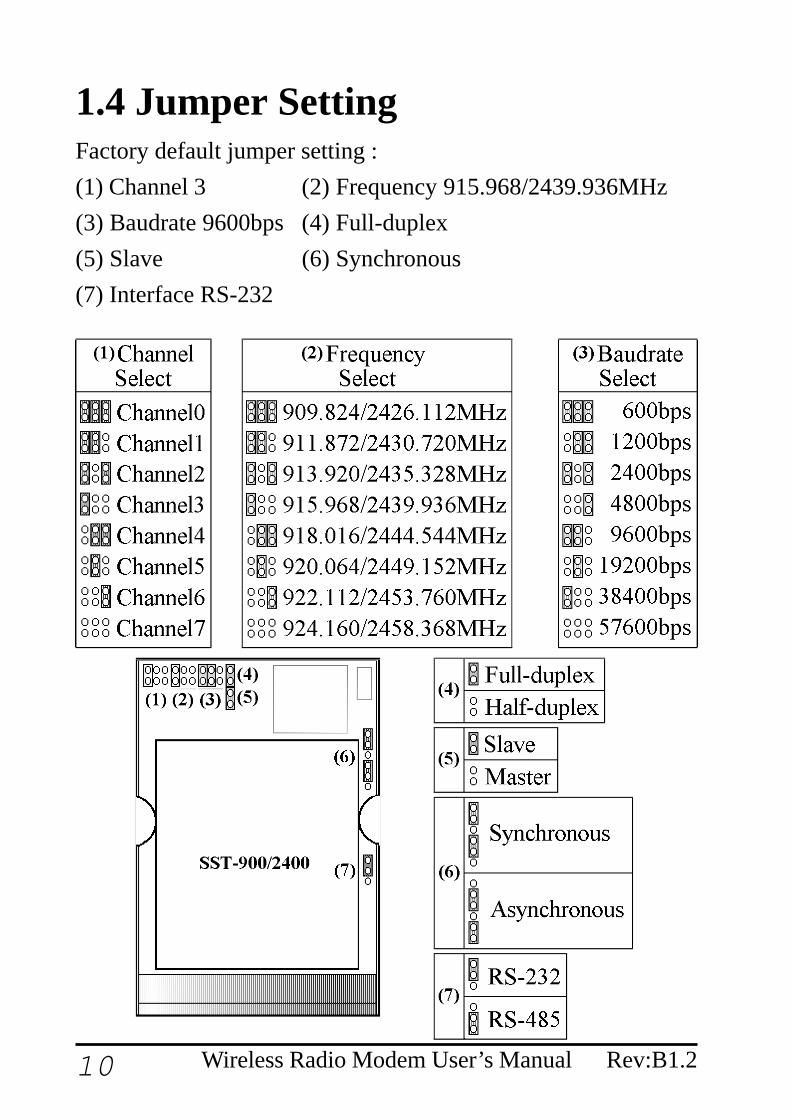
1.4 Jumper SettingFactory default jumper setting :(1) Channel 3 (2) Frequency 915.968/2439.936MHz(3) Baudrate 9600bps (4) Full-duplex(5) Slave (6) Synchronous(7) Interface RS-232

11Wireless Radio Modem User’s ManualRev:B1.2
1.5 Wire ConnectionWire Connection for PC’s RS-232 and SST-900/2400 :1. The jumper(7) position in
RS-232 side
2. Connect SST-900/2400’sGND to CA-0910’s GND,TX to TX and RX to RX.
3. Connect CA-0910’s DB-9female connector to PC’sR S - 2 3 2 D B - 9 m a l econnector.
Wire Connection for I-7000 and SST-900/2400 via RS-4851. The jumper(7) position in
RS-485 side.
2. D+ of SST-900/2400 to D+of RS-485 bus.
3. D- of SST-900/2400 to D-of RS-485 bus.
12 Wireless Radio Modem User’s Manual Rev:B1.2
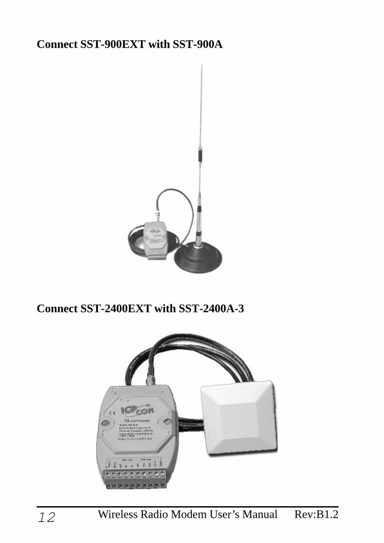
Connect SST-900EXT with SST-900A
Connect SST-2400EXT with SST-2400A-3

13Wireless Radio Modem User’s ManualRev:B1.2
Connect SST-2400EXT with SST-2400A-12
Connect SST-2400EXT with SST-2400A-13
14 Wireless Radio Modem User’s Manual Rev:B1.2
Rear View
Front View Side View
Bottom View
Top View
1.6 Dimension1.6.1 SST-900EXT and SST-2400EXT

15Wireless Radio Modem User’s ManualRev:B1.2
1.6.2 DIN-RAIL Mounting
Antenna ofSST-2400EXT
Antenna ofSST-900EXT

16 Wireless Radio Modem User’s Manual Rev:B1.2
1.6.4 Pannel Mounting
17Wireless Radio Modem User’s ManualRev:B1.2
2 Configuration2.1 Full-duplex and Half-duplex
Full-duplex is to transimit and receive data at the sametime, and half-duplex is to transimit and receive data at seperatetime. While using full-duplex mode, only peer-to-peer operationis available. For work in multi-point operation, half-duplex is theonly choice.
While working in full-duplex mode, one of the two com-munication modules is set as master and the other is set as slave.And both modules have same baudrate, frequency and channelselect.
While working in half-duplex mode, the all modules havethe same configuration. The baudrate and frequency select needall the same, and all modules select slave mode. The channel se-lect is invalid for half-duplex mode. In half-duplex mode, onlyone module may transimit at the same time. If more than one mod-ule transimit data at the same time, the received data is not correct.

18 Wireless Radio Modem User’s Manual Rev:B1.2
2.2 Synchronous and AsynchronousIn synchronous mode is that the serial data need to
specificed format, 1 start bit, 8 data bits, no parity bit and 1 stopbit.The data is readed in fixed data format and transimt. The re-ceiver receive the data and output the data in fixed data format.
In asynchronous mode, the data is sampled and thentransimit. And the receiver received data and regenerate the databy the sampled data. For the limitation of sampling rate of 32KHz,the data rate is limited to 14.4Kbps in order to prevent the distor-tion of the output data. While using asynchronous mode, only RS-232 interface may work.

19Wireless Radio Modem User’s ManualRev:B1.2
2.3 Configuration SelectThere are 3 different configuration of SST-900 and SST-
2400 modules.Operation Mode 1 : Full-duplex, Synchronous
Peer-to-peer communicationOne master configuration and one slave configurationMax baudrate : 19200bpsFixed data format : 1-bit start, 8-bit data, no parity, 1-bit stop
Operation Mode 2 : Half-duplex, SynchronousMultiple nodescommunicationAll slave configurationMax baudrate : 57600bpsFixed data format : 1-bit start, 8-bit data, no parity, 1-bit stopDelay between transimit and receiveChannel select is disabled
Operation Mode 3 : Full-duplex, AsynchronousPeer-to-peerOne master configuration and one slave configurationMax baudrate : 14400bpsVariable data formatRS-232 interface only

20 Wireless Radio Modem User’s Manual Rev:B1.2
2.4 Operation Mode 1Operation mode 1 is full-duplex, synchronous, fixed data
format communication configuration. The mode is the most com-mon mode for peer-to-peer communication. This mode may en-code the input data streams and transimit to the other SST modules.And the other modules may decode the data streams and put intoserial communication line. This may decrease the communicationerror rate and increase the communication stability.Jumper Seeting : Refer Sec.1.4 for detail(1) : Select one channel(2) : Select one frequency(3) : Select one baudrate, max 19200 bps(4) : Full-duplex(5) : Select master or slave(6) : Synchronous(7) : RS-232 or RS-485Benefits :1. Most stable communication2. Full-duplex communicationLimitation :1. Fixed data format2. Peer-to-peer only3. Baudrates up to 19200 bps
21Wireless Radio Modem User’s ManualRev:B1.2
2.5 Operation Mode 2Operation mode 2 is half-duplex, synchronous, fixed data
format communication configuration. This mode may operate forcommunication with two or more SST modules. While operationin this mode, all SST modules are virtually connect together withan invisible line. All communication data broadcast to every SSTmodule. The mode is suitable to build a wireless communicationnetwork with max baudrate 57600bps. For the fewer error correc-tion mechanism, the mode may have more communication errorthan operation mode 1.Jumper Seeting : Refer Sec.1.4 for detail(1) : Channel select is useless(2) : Select one frequency(3) : Select one baudrate(4) : Half-duplex(5) : Slave(6) : Synchronous(7) : RS-232 or RS-485Benefits :1. Multiple nodes communication2. Baudrates up to 57600 bpsLimitation :1. Fixed data format2. Half-duplex only

22 Wireless Radio Modem User’s Manual Rev:B1.2
2.6 Operation Mode 3Operation mode 3 is full-duplex, asynchronous commu-
nication configuration. This mode is work by the way of sampleand rebuild. The SST module samples the serial input (RX of RS-232) and transimit to the other SST module, and receive from RFto rebuild the serial output (TX of RS-232). For the limitation ofsampling rate, the data waveform may be distorition for higherdata rate.Jumper Seeting : Refer Sec.1.4 for detail(1) : Channel select is useless(2) : Select one frequency(3) : Baudrate select is useless(4) : Full-duplex(5) : Select master or slave(6) : Asynchronous(7) : RS-232Benefits :1. Full-duplex communication2. Variable data formatsLimitation :1. Peer-to-peer only2. Baudrates up to 14400 bps3. RS-232 interface only
23Wireless Radio Modem User’s ManualRev:B1.2
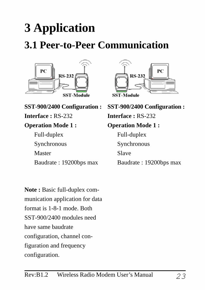
3 Application3.1 Peer-to-Peer Communication
SST-900/2400 Configuration :Interface : RS-232Operation Mode 1 :
Full-duplexSynchronousMasterBaudrate : 19200bps max
SST-900/2400 Configuration :Interface : RS-232Operation Mode 1 :
Full-duplexSynchronousSlaveBaudrate : 19200bps max
Note : Basic full-duplex com-munication application for dataformat is 1-8-1 mode. BothSST-900/2400 modules needhave same baudrateconfiguration, channel con-figuration and frequencyconfiguration.
24 Wireless Radio Modem User’s Manual Rev:B1.2
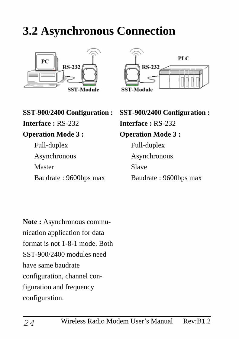
3.2 Asynchronous Connection
SST-900/2400 Configuration :Interface : RS-232Operation Mode 3 :
Full-duplexAsynchronousMasterBaudrate : 9600bps max
SST-900/2400 Configuration :Interface : RS-232Operation Mode 3 :
Full-duplexAsynchronousSlaveBaudrate : 9600bps max
Note : Asynchronous commu-nication application for dataformat is not 1-8-1 mode. BothSST-900/2400 modules needhave same baudrateconfiguration, channel con-figuration and frequencyconfiguration.
25Wireless Radio Modem User’s ManualRev:B1.2
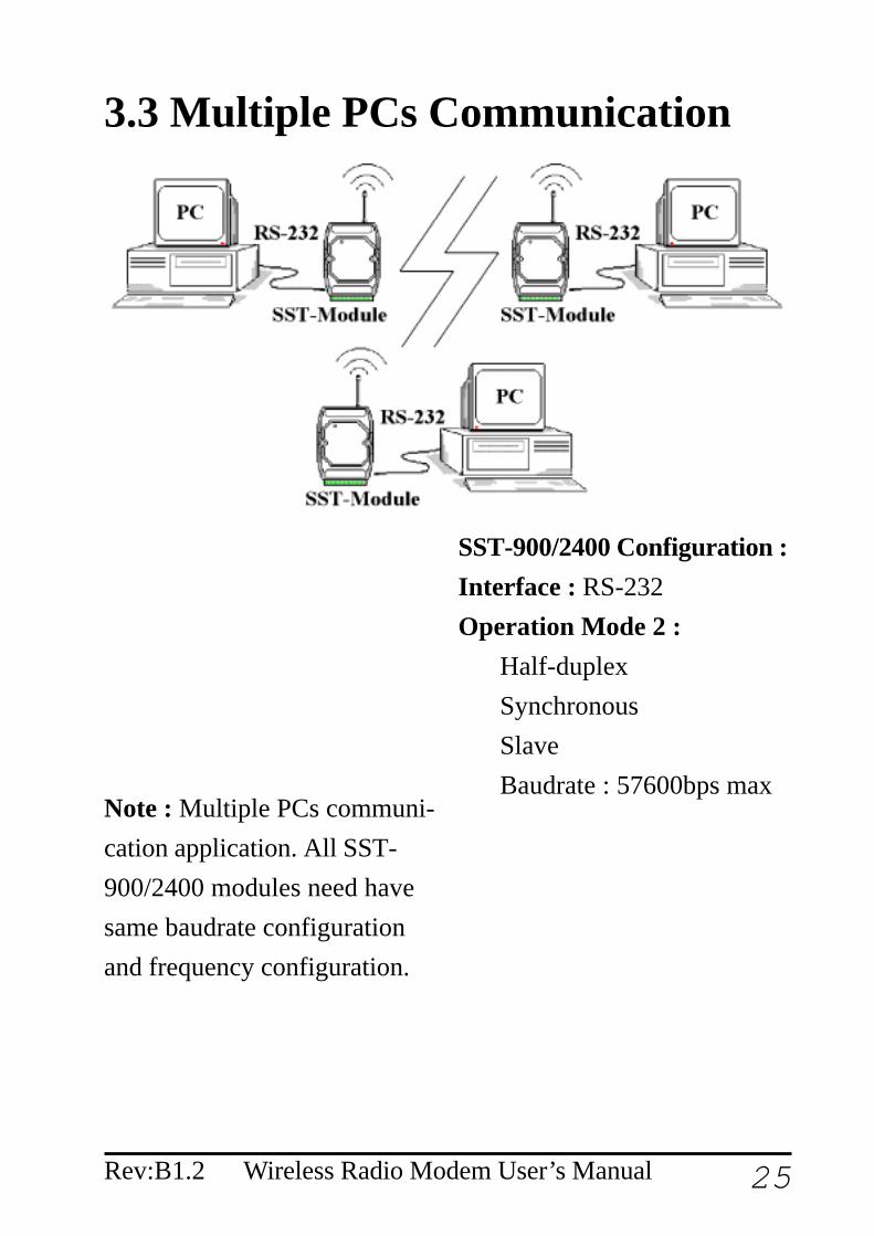
3.3 Multiple PCs Communication
SST-900/2400 Configuration :Interface : RS-232Operation Mode 2 :
Half-duplexSynchronousSlaveBaudrate : 57600bps max
Note : Multiple PCs communi-cation application. All SST-900/2400 modules need havesame baudrate configurationand frequency configuration.

26 Wireless Radio Modem User’s Manual Rev:B1.2
3.4 Connect I-7000 Modules
SST-900/2400 Configuration :Interface : RS-232Operation Mode 1 :
Full-duplexSynchronousMasterBaudrate : 19200bps max
SST-900/2400 Configuration :Interface : RS-485Operation Mode 1 :
Full-duplexSynchronousSlaveBaudrate : 19200bps max
Note : Connect I-7000 mod-ules with SST-900/2400modules. Both SST-900/2400modules need have samebaudrate configuration, chan-nel configuration and fre-quency configuration.
27Wireless Radio Modem User’s ManualRev:B1.2
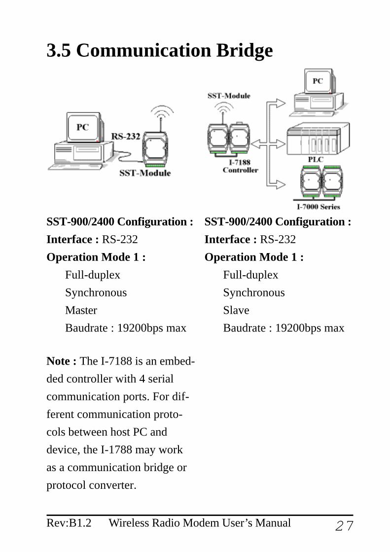
3.5 Communication Bridge
SST-900/2400 Configuration :Interface : RS-232Operation Mode 1 :
Full-duplexSynchronousMasterBaudrate : 19200bps max
SST-900/2400 Configuration :Interface : RS-232Operation Mode 1 :
Full-duplexSynchronousSlaveBaudrate : 19200bps max
Note : The I-7188 is an embed-ded controller with 4 serialcommunication ports. For dif-ferent communication proto-cols between host PC anddevice, the I-1788 may workas a communication bridge orprotocol converter.

28 Wireless Radio Modem User’s Manual Rev:B1.2
3.6 Network Communication
SST-900/2400 Configuration :Interface : RS-232 or RS-485Operation Mode 2 :
Half-duplexSynchronousSlaveBaudrate : 57600bps max
Note : Builde wireless networkvia SST-900/2400 and I-7188.The network is master-slavestructure, and only one mastermay exist at the smae time.


![FEATURES & BENEFITS€¦ · 6' [1.8m] GB, GBA 12" [305mm] 18" [457mm] 30" [760mm] 2 Duplex 3 Duplex 4 Duplex 5 Duplex 6 Duplex • Hard-Wired models • Cord-Ended models CUSTOM PLUGMOLD](https://img.pdfslide.us/doc/110x75/5fc2103c504884668467a733/features-benefits-6-18m-gb-gba-12-305mm-18-457mm-30.jpg)


![Duplex and Super Duplex [Fittings and Flanges] final](https://img.pdfslide.us/doc/110x75/61a6ddf752ba2a16af77519c/duplex-and-super-duplex-fittings-and-flanges-final.jpg)