Embed Size (px)
Citation preview

In-band Full Duplex Radio: A survey
Ashish Kumar Rao
Research Scholar, Department of Electronics Engineering Institute of Engineering and Technology
Lucknow, U.P., India
Rajiv Kumar Singh
Assistant Professor Department of Electronics Engineering Institute of Engineering and Technology
Lucknow, U.P., India
Neelam Srivastava
Director, Rajkiya Engineering College Kannauj, U. P., India
Abstract
Massive development in the field of wireless communication
enables utmost utilization of the precious spectrum. However,
many devices are working in half-duplex (HD) mode and
consume valuable resources by employing frequency-division
or time-division. The recent research shows that the full-
duplex (FD) system is one of the most promising solution for
saving the time and frequency resource. The full duplex
system allows simultaneous communication at the same
frequency. Thus, the operation in full duplex reduce the
spectrum requirement of a given communication system by
half. In this paper we have presented the survey of self-
interference in FD communication and discussed the
cooperative spectrum sensing scenario in FD Cognitive radio.
Keywords: Full Duplex communication, self-interference,
Cognitive radio networks.
Introduction With the increasing number of new devices such as smart
phone, tablet, laptops and their applications in recent years, the
data traffic especially mobile video data traffic has increased
[1, 2]. Therefore, it is important to increase the network
capacity and spectral efficiency to overcome the spectrum
scarcity problem and make the devices to efficiently use these
bandwidth-consuming applications and services. Full Duplex
communication is one of the liberal of promises concept to
improve spectral efficiency, and resource utilization in cellular
networks [3, 4]. For efficient spectrum utilization, Cognitive
Radio (CR) has been recommended as the best solution. CR
permits the secondary user (unlicensed) to use licensed bands
allocated to primary users (licensed). In conventional CR
systems, spectrum sensing is done before data transmission in
each time slot, which is widely known as the “listen-before-
talk” protocol. This procedure takes more time in sensing in
comparison to data transmission and during the data
transmission sensing is not performed. Hence, this protocol
has two inherent problems: 1) reduced transmission time due
to sensing, 2) burdening of spectral resources as two bands are
used for communication. On the other hand, full duplex (FD)
cognitive radio works on the principle of “listen and talk”
protocol [5]. In this protocol, the spectrum sensing and
reporting is performed simultaneously in the same channel,
which doubles the spectral efficiency in comparison to (HD-
CR).
Therefore, this paper presents limitation of previous
technology of half duplex communication and the research
advances that enable FD communications for wireless
networks, as well as the state-of-the-art research and
development and related information, will be very useful for
researchers and engineers. This is the primary motivation for
writing this paper.
The remaining paper is organised as: in second part we have
discussed the introduction of FD communication and self-
interference cancellation techniques, current state of art and
key application in FD communication. Self-interference
cancellation mechanism is discussed in second part and
Spectrum sensing in CR network is discussed in third part of
the paper. In last section, we have discussed some challenges
and conclusion.
Full Duplex Communication
In FD communication data transmission and reception is
performed simultaneously at the same frequency, which
doubles the spectral efficiency. However, due to line-of-sight
component known as self-interference (SI), it has been
considered as impractical since last few years. Hence, it was
very tough to extract the desired signal due to overwhelm the
receiver. Hence, SI problem remained a big issue until
recently. In recent years, the enormous growth in the area of SI
suppression in FD systems makes the revolution in FD
communications and their application in cellular
communication and cognitive radio communication (CRC).
International Journal of Applied Engineering Research ISSN 0973-4562 Volume 14, Number 2, 2019 (Special Issue) © Research India Publications. http://www.ripublication.com
Page 183 of 189

The comparison between half duplex cognitive radio network
and full duplex cognitive radio networks are as given in below
Table 1.
Table 1: Half-Duplex vs Full-Duplex
Parameter Half Duplex
Cognitive Radio
Networks
Full Duplex Cognitive Radio
Networks
Spectrum
Sensing (SS)
The duration for
spectrum sensing is
predefined. This is not
continuous in nature.
In FD, duration for spectrum
sensing is not predefined. This
is continuous in nature.
Self-
Interference
Suppression Not applicable in HD
CRNs.
Different approaches are used
for self-interference
suppression in full-duplex
CRNs such as active and
passive approach.
Secondary
Transmit
Power
Increase in the power
in HD-CRN increases
the throughput also.
In full duplex CRN, there is a
trade-off between throughput
and power.
PR Activity PR activity in half
duplex CRNs
monitors primary user
with several model.
In FD CRN, PU activity
becomes more reliable due to
continuous spectrum sensing.
Security Less secure in
comparison to FD
CRNs.
Anti-jamming antennas in FD
CRNs mitigate the impact of
various eavesdroppers.
Self-Interference Cancellation
The main impediment in FD communication is to sufficiently
suppress the SI, as shown in Fig. 1, depending on internodes
distance, the self-interference varies in the range of 50–110
dB, which is greater than the received signal.
Figure 1: Full Duplex communication [6]
Figure 2: Full-duplex self-interference [6]
It is shown in Fig. 2 that the SI dominates on the desired
received signal. This creates the problem in Analog-to-Digital
Converters (ADC), because most dynamic range is affected by
the SI. Therefore, the signal to noise ratio (SNR) is low and
effective bits for the desired received signal are much smaller.
Hence, it is necessary to reduce SI before ADC in analog
circuit.
There are three major techniques for self-interference
cancellation, as follows [6]
A. Antenna Placement
Fig. 3, shows the SI cancellation method in FD communication.
In this multiple antenna placement, the signal from the
transmitting antenna cancel with each other. Hence the self-
interference is reduced significantly in narrowband signal. This
antenna placement has the limitation that it effectively works
only on narrowband signals.
Figure 3: Full duplex using multiple antennas [8]
B. Active Analog Cancellation
As discussed that the problem in ADC output SNR occurs due
to SI. Hence, to overcome this problem, an active analog
cancellation circuit has been implemented as illustrated in Fig.
4. In this circuit the propagation channel has been adaptively
duplicated from the transmitting to the receiving antenna,
which consequently removes the SI.
Figure 4: Full duplex using active analog cancellation [6]
C. Active Digital Cancellation
The residual interference (RSI) is mitigated through applying
active digital cancellation scheme after analog self- interference
cancellation scheme. Active digital cancellation is seen as an
adaptive filter design procedure in which a training sequence is
needed to train the filter tap weights, which reduce the residual
interference energy. In this procedure once the filter
RSSI ∑ Attenuation
& Delay
RF Baseband
Baseband RF
Balun Cancellation
TX1
Antenna Cancellation
ADC
ℓ
ℓ
𝜋 𝑝ℎ𝑎𝑠𝑒 𝑠ℎ𝑖𝑓𝑡𝑒𝑟
Digital
Cancellation
d 𝑑 +𝜆
2
RX TX2
RF
Interference
Cancellation
TX
Sig
nal
: Signal of interest
: Self-interference
TX TX
RX RX
Node
2
Node
1
International Journal of Applied Engineering Research ISSN 0973-4562 Volume 14, Number 2, 2019 (Special Issue) © Research India Publications. http://www.ripublication.com
Page 184 of 189

coefficients are obtained, the data are transmitted and the self-
interference is mitigated.
Current state of the art
In the literature, many SI reduction techniques have been
surveyed. In [7], author proposed several interference
suppression mechanisms and by the experimental results shows
the reduced self-interference level. This make the full duplex
procurable to achieve higher rates than half duplex. A FD
decode-and-cancel network scheme has been proposed in [8],
for improved interference cancellation. This scheme is able to
overcome the problem of SI at the FD node. In [9], two models
for self-interference cancellation have been proposed for FD
communication. The SI is considered as random and unknown
in first model, while in the second model, the SI is considered
as precisely known. In-band full-duplex Wi-Fi radio design and
implementation is presented in [10], which reduces the SI level
by including new analog and digital cancellation approach. In
[11], a balanced/unbalanced (Balun) transformer is taken in
account signal inversion in addition to adaptive cancellation in
designing and implementing a FD radio. Further, the resource
allocation problem in case of FD is discussed in many research
papers. In [12], for wireless relay networks in half duplex mode
and full duplex mode, the optimal resource allocation schemes
have been proposed.
However, the dynamic resource allocation techniques have
been proposed in FD as well as HD modes, which maximize
the network throughput under a certain delay constraint. In
[13], optimum power allocation schemes are studied. In this
scheme, individual power constraints, lower and upper bounds
on the capacity of the channel model have been analytically
obtained. In [14], to improve throughput of FD wireless link, a
power allocation scheme and two different models are
proposed and analyzed at a given certain delay constraint. In
[15], to improve the sum rate of FD bidirectional transmissions,
an optimal dynamic power allocation technique is proposed.
Key Application Scenarios
The main feature of FD technology is simultaneous data
transmission and reception, and its potential to double spectral
efficiency. This paper, considers the following three main
applications 1) Full duplex bidirectional communications, 2)
Full duplex cooperative communications, and 3) full duplex
cognitive radio networks (CRN).
Figure 5: Full-duplex bidirectional communication [6]
Fig. 5 shows a pair of FD transmitter and receiver. Here the
two FD nodes A and node B transmit and receive data
simultaneously in the same frequency band. The NA and NB
antennas are connected with node A and bode B respectively.
The linkAB, is represents the transmission link from the node A
to node B, and transmission link from node B to node A is
denoted as linkBA.
Each node A and B receives the two signals; one, the required
signal from second node, and second, SI signal from its own
transmitting antenna. Thus, if the SI is removed completely,
spectral efficiency gets double in case of FD as compared to
HD communications.
Fig. 6 shows the next application of FD in cooperative
communications. This is generally haves three nodes, source
node, relay node, and a destination node. In this model the
source node transmits its signal to destination node and relay
node provides the diversity to the source node by receiving,
amplifying and retransmitting the source signal. In Fig. 6, we
consider that the linkSR is presented the transmission links from
node S to node R, the transmission link from node R to node D
is denoted as linkRD. Similar to the FD bidirectional
transmission, the spectral efficiency can be doubled in FD
cooperative communication, if the FD transmission is used at
the relay node.
Figure 6: Full- duplex cooperative communications [6]
Now, we consider FD-CRNs. Spectrum sensing (SS) is
performed by SU to identifying white spaces that can be used
by SUs. Traditionally in half duplex systems, the SUs does not
transmit their data during the SS and does not perform sensing
during the data transmission. Hence, the precious resource of
spectrum gets wasted and unable to sense PU activity
efficiently. On the other hand, as shown in Fig. 7, if the SUs
works in FD mode, it performs the SS and data transmission
simultaneously and overcome the problems of conventional
HD CRNs.
Figure 7: Full-duplex cognitive radio network [8]
Apart from the discussed applications, FD communication is
applicable to many others aspects, such as Ad hoc networks,
SU2
Sensing
PU
SU1
Ant2 Ant1
Self-interference
Transmission
linkSR LinkRD
.
.
.
.
.
.
.
.
R S D
Node A
Node B
linkAB
.
.
.
.
.
.
linkBA
International Journal of Applied Engineering Research ISSN 0973-4562 Volume 14, Number 2, 2019 (Special Issue) © Research India Publications. http://www.ripublication.com
Page 185 of 189
local area networks, cellular networks, vehicle communication,
satellite communication etc. Taking an example of FD cellular
network, where the base station operates in FD, and support
uplink and downlink communications simultaneously, which
can double the spectral efficiency.
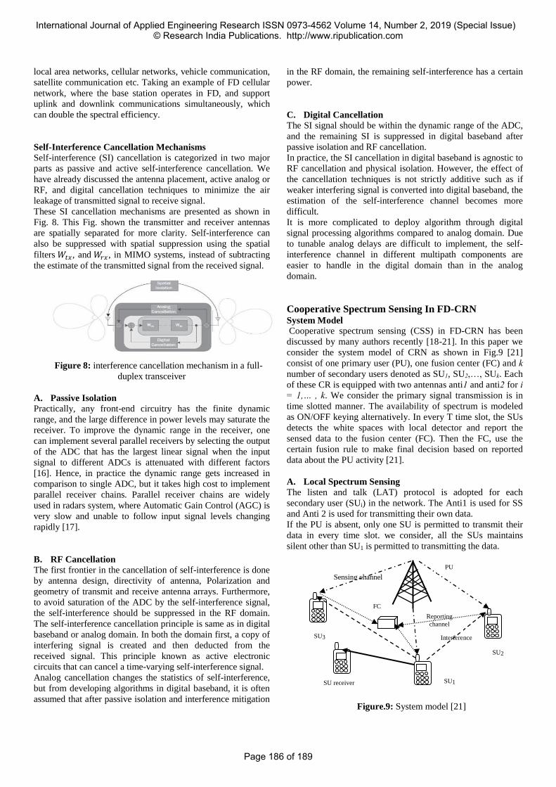
Self-Interference Cancellation Mechanisms
Self-interference (SI) cancellation is categorized in two major
parts as passive and active self-interference cancellation. We
have already discussed the antenna placement, active analog or
RF, and digital cancellation techniques to minimize the air
leakage of transmitted signal to receive signal.
These SI cancellation mechanisms are presented as shown in
Fig. 8. This Fig. shown the transmitter and receiver antennas
are spatially separated for more clarity. Self-interference can
also be suppressed with spatial suppression using the spatial
filters 𝑊𝑡𝑥, and 𝑊𝑟𝑥, in MIMO systems, instead of subtracting
the estimate of the transmitted signal from the received signal.
Figure 8: interference cancellation mechanism in a full-
duplex transceiver
A. Passive Isolation
Practically, any front-end circuitry has the finite dynamic
range, and the large difference in power levels may saturate the
receiver. To improve the dynamic range in the receiver, one
can implement several parallel receivers by selecting the output
of the ADC that has the largest linear signal when the input
signal to different ADCs is attenuated with different factors
[16]. Hence, in practice the dynamic range gets increased in
comparison to single ADC, but it takes high cost to implement
parallel receiver chains. Parallel receiver chains are widely
used in radars system, where Automatic Gain Control (AGC) is
very slow and unable to follow input signal levels changing
rapidly [17].
B. RF Cancellation
The first frontier in the cancellation of self-interference is done
by antenna design, directivity of antenna, Polarization and
geometry of transmit and receive antenna arrays. Furthermore,
to avoid saturation of the ADC by the self-interference signal,
the self-interference should be suppressed in the RF domain.
The self-interference cancellation principle is same as in digital
baseband or analog domain. In both the domain first, a copy of
interfering signal is created and then deducted from the
received signal. This principle known as active electronic
circuits that can cancel a time-varying self-interference signal.
Analog cancellation changes the statistics of self-interference,
but from developing algorithms in digital baseband, it is often
assumed that after passive isolation and interference mitigation
in the RF domain, the remaining self-interference has a certain
power.
C. Digital Cancellation
The SI signal should be within the dynamic range of the ADC,
and the remaining SI is suppressed in digital baseband after
passive isolation and RF cancellation.
In practice, the SI cancellation in digital baseband is agnostic to
RF cancellation and physical isolation. However, the effect of
the cancellation techniques is not strictly additive such as if
weaker interfering signal is converted into digital baseband, the
estimation of the self-interference channel becomes more
difficult.
It is more complicated to deploy algorithm through digital
signal processing algorithms compared to analog domain. Due
to tunable analog delays are difficult to implement, the self-
interference channel in different multipath components are
easier to handle in the digital domain than in the analog
domain.
Cooperative Spectrum Sensing In FD-CRN System Model
Cooperative spectrum sensing (CSS) in FD-CRN has been
discussed by many authors recently [18-21]. In this paper we
consider the system model of CRN as shown in Fig.9 [21]
consist of one primary user (PU), one fusion center (FC) and k
number of secondary users denoted as SU1, SU2,…, SUk. Each
of these CR is equipped with two antennas anti1 and anti2 for i = 1,… , k. We consider the primary signal transmission is in
time slotted manner. The availability of spectrum is modeled
as ON/OFF keying alternatively. In every T time slot, the SUs
detects the white spaces with local detector and report the
sensed data to the fusion center (FC). Then the FC, use the
certain fusion rule to make final decision based on reported
data about the PU activity [21].
A. Local Spectrum Sensing
The listen and talk (LAT) protocol is adopted for each
secondary user (SUi) in the network. The Anti1 is used for SS
and Anti 2 is used for transmitting their own data.
If the PU is absent, only one SU is permitted to transmit their
data in every time slot. we consider, all the SUs maintains
silent other than SU1 is permitted to transmitting the data.
Figure.9: System model [21]
SU1
SU2
SU3
SU receiver
Interference
Reporting
channel
Sensing channel
FC
PU
International Journal of Applied Engineering Research ISSN 0973-4562 Volume 14, Number 2, 2019 (Special Issue) © Research India Publications. http://www.ripublication.com
Page 186 of 189

The PU and SU1 are the two signal presents in the
environment, each of these can be active or silent. Hence, on
the behalf of these signal there are four cases should be clearly
defined as: 𝐻00 , denotes that the primary transmitter is not
transmitting the data and secondary transmitter not detecting
the status of PT. Hence, ST gives the false alarm and does not
transmit the data. 𝐻01, denotes that the primary transmitter is
active and secondary transmitter is silent. 𝐻10 , denotes that
the secondary transmitter transmit data. Hence, in this case,
the consumed energy is utilized to perform sensing and
transmitting of data. 𝐻11, denotes the primary transmitter and
secondary transmitter both active at a same time due to miss-
detection.
For SU1, the suppression of received signal at Ant11, is the
residual self-interference (RSI). The RSI is modeled according
to Gaussian distributed [22-24], and the variance is
proportional to SU1’s transmit power. Hence, the received
signal at Ant1, presented as:
𝑦1 = {
ℎ1𝑠𝑝+𝑤+𝑢1, 𝐻00
𝑤+𝑢1 𝐻10
ℎ1𝑠𝑝+ 𝑢1 𝐻01
𝑢1 𝐻11
(1)
Where, 𝑠𝑝 is the PU’s signal, ℎ1 ∼ 𝐶𝒩(0, 𝜎12)σ12 denotes the
Rayleigh channel gain from the PU to Ant1, 𝑢1∼ 𝐶𝒩(0, 𝜎𝑢2),
shows the complex-valued Gaussian noise and 𝑤 ∼ 𝐶𝒩(0,𝜎11
2 𝜎𝑠2), shows the residual self-interference term with 𝜎𝑠
2 and
𝜎112 presents the SU1’s signal power and the level of
suppression of SI respectively.
For SUs other than i=1, other SUi (𝑖 ≠1), signal from SU1 is
deported as interference. Then we can get 𝑦𝑖 as:
𝑦𝑖 = {
ℎ𝑖𝑠𝑝+ℎ1𝑖𝑠1+𝑢𝑖, 𝐻00
ℎ1𝑖𝑠1+𝑢𝑖, 𝐻10
ℎ𝑖𝑠𝑝+ 𝑢𝑖, 𝐻01
𝑢𝑖 𝐻11
(2)
where 𝑠1 Presents the SU1’s signal, ℎ𝑖 ∼ 𝐶𝒩(0, 𝜎𝑖2), denotes
channel gain from PU to SU1 and ℎ1𝑖 ∼ 𝐶𝒩(0, 𝜎1𝑖2 ) presents
the channels gain from the PU to SUi. Here, we consider SUs
are use the energy detection technique for SS, in which, the test
statistics Mi is used to calculate average power in one time slot.
𝑀𝑖 = 1
𝑁𝑠∑ |𝑦𝑖(𝑛)|2𝑁𝑠
𝑛=1 , (3)
In this model, SU uses energy detection to perform sensing of
signal, where Ns is the total number of sample taken and Mi is the received signal energy and number of sample Ns = fs*T, with fs sampling rate. yi(n) is the nth sample of the received
signal. Local detection threshold would vary accordingly as
received signal activity because the all SU varies according to
SU1’s activity
Let X = 0/1 presents the state of SU1 as silent/active. Let us
consider 𝜖𝑖𝑋 denotes decision threshold at SUi then local false
alarm probabilities and probability of miss detection given by:
𝑃𝑖𝑚𝑋 (𝜖𝑖𝑋) = 𝑃𝑟(𝑀𝑖 < 𝜖𝑖𝑋|ℋ𝑋1) (4)
𝑃𝑖𝑓𝑋 (𝜖𝑖𝑋) = 𝑃𝑟(𝑀𝑖 < 𝜖𝑖𝑋|ℋ𝑋0) (5)
B. Data Reporting and decision-making process at FC
Here, let us consider that the SUs sends their own decision to
the FC. By considering that there is no error present in data
reporting process. The ‘OR’ fusion rule is use to make final
decision. In ‘OR’ fusion rule, the FC decides that PU is present,
if at least one SU reports, that the PU is present. On the basis of
this decision, the miss detection probability and false alarm
probability is obtained as
𝑃𝑚𝑋 = ∏ 𝑃𝑖𝑚
𝑋𝑘𝑖=1 ,
𝑃𝑓𝑋 = 1 − ∏ 1 − 𝑃𝑖𝑓
𝑋𝑘𝑖=1 , (6)
Analysis of CSS in the FD-CRN
This section mainly focuses on sensing performance and
throughput in cooperative spectrum sensing (CSS) using LAT
protocol.
A. Probabilities of Miss Detection and Probabilities False Alarm
In (3), the y (n) is independent identically distributed (iid) in
any certain period of time and Ns are large enough. The
probability density function (PDF) of Mi can be approximated
by a Gaussian distribution [18]. As presented in [19], the
probability density function (PDF) of the test statistics at any
SUi, is according to (1) and (2). Here we consider that the SU1’s
and PU’s signals is modulated as phase shift keying (PSK) with
all the independent channels. 𝜎𝑃2 denotes the PU’s signal
power. The interference term ℎ1𝑖𝑠1 is modeled as random
complex gaussian distributed. We can write the PDF of
𝑀𝑖(𝑖 ≠1) and 𝑀𝑖, in similar forms. Statistical properties and
their details description are presented in Table I. Here signal to
noise ratio (SNR) from the PU to SUi and INR due to SU1 is
denoted as 𝛾𝑖 = 𝜎𝑖
2𝜎𝑃2
𝜎𝑢2 and 𝛾1𝑖 =
𝜎1𝑖2 𝜎𝑠
2
𝜎𝑢2 , respectively.
Table 1: Hypothesis Testing
Hyp
othe
sis
PU SU1 Mean E[Mi] Var[Mi]
H00 Idle Silent 𝜎𝑢2
𝜎𝑢4
𝑁𝑠
H01 Busy Silent (1 + 𝛾𝑖)𝜎𝑢2
(1 + 𝛾𝑖)2𝜎𝑢
4
𝑁𝑠
H10 Idle Active (1 + 𝛾1𝑖)𝜎𝑢2
(1 + 𝛾1𝑖)2𝜎𝑢
4
𝑁𝑠
H11 Busy Active (1 + 𝛾𝑖
+ 𝛾1𝑖)𝜎𝑢2
(1 + 𝛾𝑖 + 𝛾1𝑖)2𝜎𝑢
4
𝑁𝑠
Using Table I, the local miss detection probabilities and the
probability of false alarm at SUi can be derived from (4) and
(5) as:
𝑃𝑖𝑚0 (𝜖𝑖0) = 1 − 𝑄 ((
𝜖𝑖0
(1 + 𝛾𝑖)𝜎𝑢2
− 1) √𝑁𝑠),
𝑃𝑖𝑓0 (𝜖𝑖0) = 𝑄 ((
𝜖𝑖0
𝜎𝑢2 − 1) √𝑁𝑠),
𝑃𝑖𝑚1 (𝜖𝑖1) = 1 − 𝑄 ((
𝜖𝑖1
(1 + 𝛾𝑖 + 𝛾1𝑖)𝜎𝑢2
− 1) √𝑁𝑠),
𝑃𝑖𝑚1 (𝜖𝑖1) = 𝑄 ((
𝜖𝑖1
(1 + 𝛾1𝑖)𝜎𝑢2
− 1) √𝑁𝑠),
(7)
International Journal of Applied Engineering Research ISSN 0973-4562 Volume 14, Number 2, 2019 (Special Issue) © Research India Publications. http://www.ripublication.com
Page 187 of 189

Where, Q(.) is complementary cumulative distribution function
of standard Gaussian function.
Q(x) = 1
√2π∫ exp (−
t2
2) dt
∞
x.
The miss detection probability and false alarm probability can be presented as [19, 21], respectively,
𝑃𝑚 = 𝑃𝑚
0
1+ 𝑃𝑚0 − 𝑃𝑚
1
𝑃𝑓 = 𝑃𝑓
1
1+ 𝑃𝑓0− 𝑃𝑓
1
We can obtain miss detection probability and probability false
alarm for the system by substituting the equation (7) to 6), and
then to (8). Let us assume the common case, where the
maximum miss detection probability of the system is stable.
Constraints of 𝑃𝑚0 , 𝑃𝑚
1 and 𝑃𝑖𝑚𝑋 of are presented in (8), and (6)
respectively. For convenience, we fix all the probability of miss
detection 𝑃𝑖𝑚𝑋 to be the same without further optimization.
𝑃𝑖𝑚𝑋 = (𝑃𝑚)1 𝑘⁄ , ∀𝑚= 1, 2, … , 𝑘, 𝑋 = 0, 1 (9)
The respective thresholds 𝜖𝑖𝑋 can be obtained as:
𝜖𝑖0 = (𝑄−1(1−𝑃𝑚
1 𝑘⁄)
√𝑁𝑠+ 1) (1 + 𝛾𝑖)𝜎𝑢
2
𝜖𝑖1 = (𝑄−1(1−𝑃𝑚
1 𝑘⁄)
√𝑁𝑠+ 1) (1 + 𝛾𝑖 + 𝛾1𝑖)𝜎𝑢
2
From the above equation, we can observe the increase in
thresholds if RSI included in the system. Then the local false
alarm probabilities will be:
𝑃𝑖𝑓0 (𝑃𝑚) = 𝑄(𝑄−1(1 − 𝑃𝑚
1 𝑘⁄)(1 + 𝛾𝑖) + 𝛾𝑖√𝑁𝑠),
𝑃𝑖𝑓1 (𝑃𝑚) = 𝑄 (𝑄−1(1 − 𝑃𝑚
1 𝑘⁄) (1 +
𝛾𝑖
1 + 𝛾1𝑖
) +𝛾𝑖√𝑁𝑠
1 + 𝛾1𝑖
)
(10)
Putting (10) to (6) and (8), the false alarm probability of the
system can be formulated.
Now we can compare the performance of CSS-LAT protocol
and the (non-CSS) performance on the basis of equation
obtained from (7) and (8). In CSS, as presented in (9), the local
miss detection probabilities 𝑃𝑖𝑚𝑋 at higher level are permitted at
every cooperating SU and the respective local false alarm
probabilities drastically reduced. Let us consider, if there are 10
cooperative SUs and miss detection probability of system is set
to 0.01. Using (9), 𝑃𝑖𝑚𝑋 > 63%, which is comparatively large,
and 𝑃𝑖𝑓𝑋 which is reduced at their minimum level. Prosecute,
interference among two SUs may be very small level and the
result of sensing may be much authentic compared to
transmitting SU result. Hence, the performance of CSS is far
better than non-CSS CRN.
B. Secondary Throughput SU1 starts transmitting the data to the secondary receiver (SR),
once white spaces are detected. The secondary throughput can
be calculated as:
𝐶 = (1 − 𝑃𝑓)𝑙𝑜𝑔2 (1 + 𝜎𝑠
2𝜎𝑡2
𝜎𝑢2
) = (1 − 𝑃𝑓)𝑙𝑜𝑔2(1 + 𝛾𝑡)
= 1−𝑃𝑓
0
1−𝑃𝑓 0+ 𝑃𝑓
1 . 𝑙𝑜𝑔2(1 + 𝛾𝑡) (11)
Where, the Rayleigh channel variance from SU1 to the receiver is denoted as 𝜎𝑡
2 , and the SNR in transmission is denoted
as𝛾𝑡 = 𝜎𝑠
2𝜎𝑡2
𝜎𝑢2 , 𝑃𝑓
0 and 𝑃𝑓1are probability of false alarm.
From the (11), it is clear that two factors are related to transmit
power 𝜎𝑠2. As the 𝜎𝑠
2 increases, the interference to noise ratio
(INRs), (γi) also increases and 𝑃𝑓1 increases accordingly.
Besides that, the obtainable sum rate 𝑙𝑜𝑔2(1 + 𝛾𝑡) increases.
Hence, there is tradeoff between throughput and transmit power
is obtained.
Conclusion Full duplex CRNs can improve the throughput by simultaneous
sensing and transmission of data. Due to advancement in self-
interference suppression (SIS) technology, FD-CRN evolves as
the better promising solution for licensed band exploitation. In
this article, we have done extensive comparison of half duplex
(HD) and full duplex (FD) communication and also covered the
analysis of cooperative spectrum and throughput calculations.
After analyzing these parameters, we concluded that the in FD-
CRN improves the detection. References [1] C.-X. Wang, F. Haider, X. Gao, X.-H. You, Y. Yang, D.
Yuan, H. Aggoune, H. Haas, S. Fletcher, and E.
Hepsaydir, “Cellular architecture and key technologies
for 5G wireless communication networks,” IEEE
Commun. Mag., vol. 52, no. 2, pp. 122–130, 2014.
[2] A. Wunder, P. Jung, M. Kasparick, T. Wild, F. Schaich,
Y. Chen, S. Brink, I. Gaspar, N. Michailow, A. Festag,
L. Mendes, N. Cassiau, D. Ktenas, M. Dryjanski, S.
Pietrzyk, B. Eged, P. Vago, and F. Wiedmann,
“5GNOW: non-orthogonal, asynchronous waveforms for
future mobile applications,” IEEE Commun. Mag., vol.
52, no. 2, pp. 97–105, 2014.
[3] S. Hong, J. Brand, J. Choi, M. Jain, J. Mehlman, S. Katti,
and P. Levis, “Applications of self-interference
cancellation in 5G and beyond,” IEEE Commun. Mag.,
vol. 52, no. 2, pp. 114–121, Feb. 2014.
[4] X. Hong, J. Wang, C.-X. Wang, and J. Shi, “Cognitive
radio in 5G: a perspective on energy-spectral efficiency
trade-off,” IEEE Commun. Mag., vol. 52, no. 7, pp. 46–
53, July 2014.
[5] Liao, Yun, Tianyu Wang, Lingyang Song, and Zhu Han,
“Listen-and-talk: Full-duplex cognitive radio networks,”
In GLOBECOM, pp. 3068-3073. 2014.
[6] Lingyang song, Risto Wichman, yanghui Li, Zhu
Han,”Full-Duplex Communications and Networks,”
Cambridge university press, 2017.
[7] M. Duarte and A. Sabharwal, “Full-Duplex Wireless
Communications Using Off-the-Shelf Radios: Feasibility
and First Results,” in Proceedings of Asilomar
Conference on Signals, Systems and Computers
(8)
International Journal of Applied Engineering Research ISSN 0973-4562 Volume 14, Number 2, 2019 (Special Issue) © Research India Publications. http://www.ripublication.com
Page 188 of 189

(ASILOMAR), Pacific Grove, CA, Nov. 2010, pp.
1558–1562.
[8] J. Bai and A. Sabharwal, “Decode-and-Cancel for
Interference Cancellation in a Three-Node Full-Duplex
Network,” in Proceedings of Asilomar Conference on
Signals, Systems and Computers (ASILOMAR), Pacific
Grove, CA, Nov. 2012, pp. 1285–1289.
[9] A. Thangaraj, R. Ganti, and S. Bhashyam, “Self-
Interference Cancellation Models for Full-Duplex
Wireless Communications,” in International Conference
on Signal Processing and Communications (SPCOM),
Bangalore, Jul. 2012, pp. 1–5.
[10] Bharadia, E. McMilin, and S. Katti, “Full Duplex
Radios,” in Proc. ACM SIGCOMM, New York, NY,
Aug. 2013, pp. 375–386.
[11] M. Jainy, J. I. Choiy, T. M. Kim, D. Bharadia, S. Seth,
K. Srinivasan, P. Levis, S. Katti, and P. Sinha,
“Practical, Real-Time, Full Duplex Wireless,” in ACM
MobiCom, Las Vegas, Nevada, Sep. 2011, pp. 301–312.
[12] W. Cheng, X. Zhang, and H. Zhang, “Full/Half Duplex
Based Resource Allocations for Statistical Quality of
Service Provisioning in Wireless Relay Networks,” in
IEEE INFOCOM, Orlando, FL, Mar. 2012, pp. 864–872.
[13] M. J. Emadi, A. G. Davoodi, and M. R. Aref,
“Analytical Power Allocation for a Full-Duplex Decode-
and- Forward Relay Channel,” IET Communications,
vol. 7, no. 13, pp. 1338–1347, Sep. 2013.
[14] W. Cheng, X. Zhang, and H. Zhang, “QoS Driven Power
Allocation over Full-Duplex Wireless Links,” in IEEE
International Conference on Communications (ICC),
Ottawa, ON, Jun. 2012, pp. 5286–5290.
[15] ——, “Optimal Dynamic Power Control for Full-Duplex
Bidirectional-Channel Based Wireless Networks,” in
IEEE INFOCOM, Turin, Apr. 2013, pp. 3120–3128.
[16] V. Gregers-Hansen, S. Brockett, and P. Cahill, “A
Stacked A-to-D Converter for Increased Radar Signal
Processor Dynamic Range,” in Proc. Radar Conf.,
Atlanta, GA, 2001, pp. 169–174.
[17] V. Bringi and V. Chandrasekar, Polarimetric Doppler
Weather Radar: Principles and Applications. Cambridge
University Press, 2001.
[18] Santosh kumar Sabat, Prabhat Kumar Sharma, Abhay
Gandhi, “Full-Duplex Cooperative Spectrum Sensing
with Primary User Activity in Cognitive Radio
Networks” IETE Technical Review, 2017, vol 34, pp 4-
14.
[19] Santoshkumar Sabat, Abhay Gandhi, Prabhat Kumar
Sharma,” Cooperative spectrum sensing in full-duplex
CRN with primary user activity,” 10th International
Conference on Communication Systems & Networks
(COMSNETS), 2018, IEEE, pp 410-413.
[20] Santosh kumar Sabat, Prabhat Kumar Sharma, Abhay
Gandhi, “Spectrum Sensing in Mobile Full-Duplex
Cognitive Radio”, in Proc. IEEE International
Conference on Advanced Networks and
Telecommunications Systems (ANTS), Indore, India,
Dec. 2018, pp. 511-515.
[21] Yun Liao, Tianyu Wang, Lingyang Song, and Bingli
Jiao, “Cooperative Spectrum Sensing for Full-Duplex
Cognitive Radio Networks” Proceedings of the 2014
IEEE ICCS pp 56-60.
[22] F. Akyildiz, B. F. Lo, and R. Balakrishnan, “Cooperative
spectrum sensing in cognitive radio networks: a survey,”
Physical Communication, vol. 4, no. 1, pp. 40-62, 2011.
[23] Everett, A. Sahai and A. Sabharwal, “Passive self-
interference suppression for full-duplex infrastructure
nodes,” IEEE Trans. on Wireless Comm., vol. 13, no. 2,
pp. 680-694, Feb. 2014.
[24] Ashish Kuma Rao, Rajiv Kumar Singh, Neelam
Srivastava,”Full-Duplex Wireless Communiation in
Cognitive Radio Networks: A Survey” Proceedings of
the Int. National Conf. of VLSI, Communication and
Signal Processing, MNNIT, Allahabad 2018.
International Journal of Applied Engineering Research ISSN 0973-4562 Volume 14, Number 2, 2019 (Special Issue) © Research India Publications. http://www.ripublication.com
Page 189 of 189