Embed Size (px)
Citation preview
LONGITUDINAL BEAM DIAGNOSTICS FOR THE ILCINJECTORS AND BUNCH COMPRESSORS∗
P. Piot1,4, A. Bracke1, V. Demir2, C. Jing3, T. Maxwell1,4, J. G. Power3, M. M. Rihaoui1,3
1 Department of Physics, Northern Illinois University DeKalb, IL 601152 Department of Electrical Engineering, Northern Illinois University DeKalb, IL 60115
3 High Energy Physics Division, Argonne National Laboratory, Argonne, IL 60439, USA4 Accelerator Physics Center, Fermi National Accelerator Laboratory, Batavia, IL 60510, USA
Abstract
We present a diagnostics suite and analyze techniquesfor setting up the longitudinal beam dynamics in Inter-national Linear Collider injectors and bunch compressors.Techniques to measure the first order moments and recoverthe first order longitudinal transfer map of the injector’s in-tricate bunching scheme are presented. Coherent transitionradiation diagnostics needed to measure and monitor thebunch length downstream of the ∼ 5 GeV bunch compres-sor are investigated using a vector diffraction model.
INTRODUCTION
In the foreseen International Linear Collider (ILC) elec-tron and positron bunches are collided at 500 GeV inthe center-of-mass. The design luminosity requires thebunches to be as short as 100 μm (rms) at the interactionpoint [1]. A bunch compressor based on a two-stage wig-gler scheme is used to compress the bunch by a factor ∼ 30to 50 at ∼ 5 GeV downstream of the damping ring beforeentering the main linac [2].
Before injection into the damping ring both electronand positron beams undergo intricate longitudinal phasespace manipulation. The electron beam is generated viaphotoemission using a long laser pulse to mitigate spacecharge. The beam bunching is then done via ballisticbunching using sub-harmonic bunchers. After accelera-tion to 5 GeV, the beam is manipulated to reduce its frac-tional energy spread in a so-called energy compressor tosatisfy the damping ring requirements. The positron beamis manipulated in similar ways but its low energy dynam-ics is more intricate due to the transverse-longitudinal cou-pling imparted in the capture and adiabatic matching sec-tion which is optimized to collect the positrons downstreamof the convertor.
In this Paper we give an overview of our effort to de-velop several longitudinal phase space diagnostic systemsand techniques to monitor the longitudinal phase spacegymnastics along the ILC injectors and bunch compressors.Numerical simulations, hardware development along with
∗This work is supported by the U.S. D.O.E. under Contract DE-FG02-06ER41435 with Northern Illinois University and under Contract No. DE-AC02-06CH11357 with Argonne National Laboratory. The work of P.P.and T. M. is partially sponsored by the Fermi Research Alliance, LLCunder Contract No. DE-AC02-07CH11359 with the U.S. D.O.E.
experimental tests are discussed. The goal of this work is toultimately provide technique for setting-up and monitoringthe main components of ILC bunching systems.
LONGITUDINAL TRANSFER MAPFUNCTIONS
Concept
The measurement of longitudinal transfer function (LTF)consists of impressing a perturbation (e.g. photocathodedrive-laser phase shift, phase or amplitude variation of a rfcavity) around its nominal operating point and measuringthe associated effect on the time-of-flight (TOF) of the elec-tron (or positron) bunch using phase detectors and energymeasurements located downstream. This method was pio-neered in the CEBAF recirculating accelerator at JeffersonLab [3] and later implemented in an energy recovering free-electron laser [4]. Depending on the type of perturbation(phase or amplitude) and the corresponding measurement(TOF or energy change), one can in principle access all theelements of the longitudinal phase space transfer map. Forinstance varying the phase of an accelerating cavity andmeasuring the associated TOF (resp. energy) variation pro-vides information on the 〈t|t〉 [resp. 〈E|t〉] elements whosefirst order expansions under TRANSPORT formalism are theM55 (resp. M65) transfer matrix elements.
The LTF technique is in principle applicable in both elec-tron and positron injectors. In the case of the positron injec-tor, the impact on the diagnostics of the intricate couplingbetween longitudinal and transverse dynamics (in the adia-batic matching section) remains to be studied. Simulationsof the ILC electron injector proposed in Ref. [5] were per-formed to investigate the possible use of LTF as a way toset-up the bunching system in the electron injector: an ex-ample of simulated compression efficiency (〈t|t〉) patternsis presented in Fig. 1 for the nominal setting of the bunch-ing setting, and for two cases of mis-tuning of the injectorsub-harmonic buncher. We see that different parametersaffect the LTF in different ways. Here the photocathodelaser phase is varied and the phase corresponding relativeTOF change is recorded downstream of the pre-acceleratorat about ∼ 60 MeV. The simulations are performed withASTRA [6]. The simulated LTF pattern changes dependingon the sub-harmonic buncher. Such a feature demonstrates
Proceedings of PAC09, Vancouver, BC, Canada TH6REP011
Instrumentation
T03 - Beam Diagnostics and Instrumentation 3971
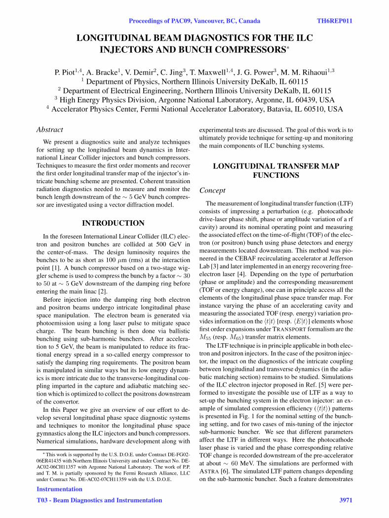
the usefulness of the technique for troubleshooting the lon-gitudinal phase space manipulation in the ILC injectors.
−0.6 −0.4 −0.2 0 0.2 0.4 0.6
−0.15
−0.1
−0.05
0
0.05
photocathode laser delay time (ns)
rela
tive
time
of a
rriv
al (
ns) case 2
case 1
nominal
Figure 1: An example of the sensitivity of longitudinaltransfer function (LTF) on the bunching system of the elec-tron injector for the nominal setting, the case when the firstsubharmonic buncher amplitude is detuned by 20% (case 1)and the case when the second sub-harmonic bunch phase ischanged by −20◦ (case 2). In these simulations, the photo-cathode drive-laser phase was varied and the correspondingtime-of-flight from the photocathode to the diagnostics lo-cated downstream of the bunching section was measured.
Similar results have been obtained for the ILC bunchcompressor. Single-particle beam dynamics simulationsof the baseline detailed in Ref. [2] were performed us-ing a one-dimensional program [7]. We modeled the LTFmeasurement by considering two phase detectors locateddownstream of each of the wiggler chicanes composing thebunch compressor. A possible measurement would con-sist of simultaneously varying the phases of the two linacsections in the bunch compressor: this would be equiva-lent to a change in the incoming bunch arrival time. Themeasurements of the relative change of TOF downstreamof each of the chicanes provide information on the associ-ated 〈t|t〉 LTF. We performed simulations for several tunesof the first bunch compressor linac phase; see Fig. 2. Thesimulations also include the phase and relative amplitudejitter of the bunch compressor linacs [taken to be respec-tively 0.25◦ (rms) and 1 × 10⁻³ (rms)]. Although the in-clusion of the linac jitter sources greatly reduces the sensi-tivity of the measured LTF on mis-settings of the phase ofthe first linac section, the technique still provides sufficientinformation for troubleshooting purposes.
Implementation & Preliminary Tests
In view of the relatively large bunch length comparedto, e.g., FEL accelerators, the required sensitivity for thetime-of-flight detector is in the 100 fs regime. Such a res-olution can be achieved using conventional rf mixing tech-niques [9]. The phase detector schematics is presented in
−40 −20 0 20 40−10
−5
0
5
δφ0
δφ1
−40 −20 0 20 40−2
−1
0
1
2
δφ0
δφ2
Figure 2: An example of the sensitivity of longitudinaltransfer function (LTF) of the bunch compressor system forthe nominal setting (red), and a change in ±2◦) in the phaseof the first stage bunch compressor linac. In these simula-tions, the incoming bunch arrival time (phase δφ0) and thethereby induced phase shift downstream of the first stage(δφ1) and second stage (δφ2) of the bunch compressor isrecorded.
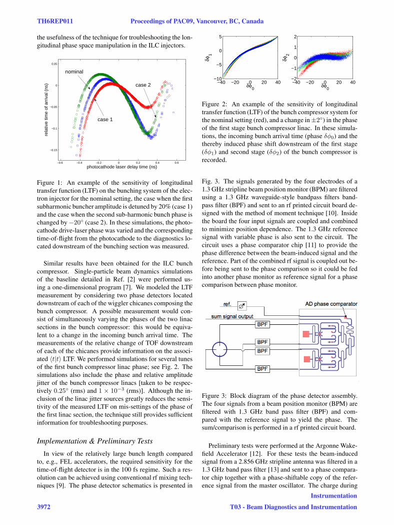
Fig. 3. The signals generated by the four electrodes of a1.3 GHz stripline beam position monitor (BPM) are filteredusing a 1.3 GHz waveguide-style bandpass filters band-pass filter (BPF) and sent to an rf printed circuit board de-signed with the method of moment technique [10]. Insidethe board the four input signals are coupled and combinedto minimize position dependence. The 1.3 GHz referencesignal with variable phase is also sent to the circuit. Thecircuit uses a phase comparator chip [11] to provide thephase difference between the beam-induced signal and thereference. Part of the combined rf signal is coupled out be-fore being sent to the phase comparison so it could be fedinto another phase monitor as reference signal for a phasecomparison between phase monitor.
Figure 3: Block diagram of the phase detector assembly.The four signals from a beam position monitor (BPM) arefiltered with 1.3 GHz band pass filter (BPF) and com-pared with the reference signal to yield the phase. Thesum/comparison is performed in a rf printed circuit board.
Preliminary tests were performed at the Argonne Wake-field Accelerator [12]. For these tests the beam-inducedsignal from a 2.856 GHz stripline antenna was filtered in a1.3 GHz band pass filter [13] and sent to a phase compara-tor chip together with a phase-shiftable copy of the refer-ence signal from the master oscillator. The charge during
TH6REP011 Proceedings of PAC09, Vancouver, BC, Canada
3972
Instrumentation
T03 - Beam Diagnostics and Instrumentation

these experiments was approximately 1 nC and the result-ing signals are shown in Fig. 4. We verified the signal wassensitive to the rf gun phase. Measurement of the LTF willbe performed in the near future.
0 100 200 300 400 500 600−0.05
0
0.05
time (ns)
BP
F o
ut (
V)
a)
0 100 200 300 400 500 600−0.05
0
0.05
time (ns)
ref.
(V)
b)
0 100 200 300 400 500 6000
1
2
time (ns)
AD
out
(V
)
c)
Figure 4: Preliminary test of the phase detector at the AWA.The beam induced signal downstream of the 1.3 GHz BPF(a) is compared to the 1.3 GHz reference signal (b) in aAnalog Device chip whose output voltage (c) is propor-tional to the phase difference between the beam-inducedand reference signals.
COHERENT TRANSITION RADIATION
Frequency-domain analysis of radiation produced by rel-ativistic picosecond-long electron beam can provide infor-mation on the beam’s charge density. In particular inter-ferometry and spectrometry of coherent transition radia-tion (TR) emitted by the bunch have proved to be powerfuldiagnostics. However, for the range of bunch length ex-pected downstream of the ILC bunch compressors (σz ∈[150 − 500] μm depending on the mode of operation; seeRef. [1]), the relevant wavelengths of the coherent radia-tion is in the sub-mm, a regime where diffraction effectssignificantly alter the response function of the bunch lengthdiagnostics based on coherent radiation. In the case of co-herent TR, for instance, the finite diameter of the metallicfoil used as a radiator will affect the mm-range spectrum ofemitted TR. Another noxious effect results from the highenergy electron beam which force the coherent TR detec-tor to be located in the near field region [i.e. the observationpoint R is at a distance much smaller than the “formationlength” associated to TR R < γλ2, where γ is the Lorentzfactor and λ the observation wavelength]. Both of these ef-fects preclude the use of the Frank-Ginzburg formula. Asoftware based on wavefront propagation was developedand used to model the generation and transport of TR [14].An example of calculation performed for a 5 GeV elec-tron striking a finite size TR radiator is depicted in Fig. 5showing the frequency response of a TR-based diagnostics.An algorithm to correct for this non-uniform response have
been developed and numerically tested [15]. Simulations ofspectral analysis of the emitted TR via dispersion througha grating have also been performed [16].
Figure 5: Transition radiation generated by a 5 GeV elec-tron in the sub-mm wavelength regime. Left plot: spectralspectral radiance with a 25 mm foil at observation distanceR = 15.24 cm (� 6”). Right plot: acceptance ratios R(ν)of viewing windows of 12.5 mm and 25.0 mm radius at adistance of 15.2 cm from the emission source.
REFERENCES
[1] See T. Raubenheimer, ”Suggested beam pa-rameters for ILC”, available at http://www-project.slac.stanford.edu/ilc/acceldev/beampar/.
[2] S. Seletskiy, P. Tennenbaum, in Proc. PAC07 (Albu-querque), 1958 (2007)
[3] G. A. Krafft, in AIP Conf. Proc. 367, 46 (1996).
[4] P. Piot, et al., PRSTAB 6, 030702 (2003).
[5] A. Curtoni, M. Jablonka, report TESLA-2001-22 availablefrom DESY (2001).
[6] K. Flottmann, ASTRA: A Space Charge Tracking Algo-rithm, available at http://www.desy.de/˜mpyflo .
[7] P. Piot, Fermilab report Beams Document 3335-v1 (2009).
[8] D. Hardy, et al., in Proc of PAC97, 2265 (2007).
[9] N. S. Sereno, et al., PRSTAB 11, 072801 (2008).
[10] M. H. Al Sharkawy, V. Demir, A. Z. Elsherbeni, Electro-magnetic Scattering using the iterative multi-region Tech-nique, Synthesis Lecture on Computational Electromagnet-ics, Morgan & Claypool Publishers, December 2007.
[11] Chip AD8302 from Analog Device, Inc.
[12] See for information http://www.hep.anl.gov/awa/ .
[13] The waveguide-type bandpass filter was designed by the Mi-crowave Filter Company, Inc.
[14] T. J. Maxwell Diffraction Analysis of Coherent Transi-tion Radiation Interferometry in Electron Linear Accelera-tors, Master of Science Thesis, Northern Illinois University(2007).
[15] T. J. Maxwell et al., in Proc. of BIW08 (Lake Tahoe) paper# TUPTPF020 (in press, 2008).
[16] T. J. Maxwell et al., manuscript in preparation.
Proceedings of PAC09, Vancouver, BC, Canada TH6REP011
Instrumentation
T03 - Beam Diagnostics and Instrumentation 3973
![ILC DR lattice - Cornell University · Yi-Peng Sun et al. ILC DR Alternative Lattice Design 20 LOW ALPHA LATTICE (3) Natural energy spread [ 10-3] 1.28 Natural bunch length [ mm ]](https://img.pdfslide.us/doc/110x75/6101cd08e8e2923eb56cf1e2/ilc-dr-lattice-cornell-university-yi-peng-sun-et-al-ilc-dr-alternative-lattice.jpg)