Embed Size (px)
Citation preview
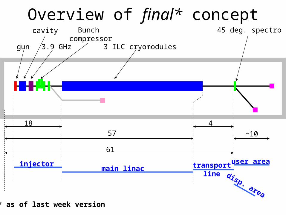
~10
18
57
4
61
gun 3.9 GHz
cavity Bunch compressor
3 ILC cryomodules
45 deg. spectro
injectormain linac
user area
disp. area
transportline
Overview of final* concept
* as of last week version
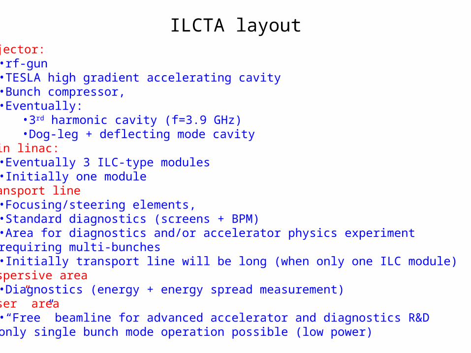
•Injector: •rf-gun•TESLA high gradient accelerating cavity•Bunch compressor, •Eventually:
•3rd harmonic cavity (f=3.9 GHz)•Dog-leg + deflecting mode cavity
•Main linac:•Eventually 3 ILC-type modules•Initially one module
•Transport line•Focusing/steering elements, •Standard diagnostics (screens + BPM)•Area for diagnostics and/or accelerator physics experimentrequiring multi-bunches•Initially transport line will be long (when only one ILC module)
•Dispersive area•Diagnostics (energy + energy spread measurement)
•“User” area•“Free” beamline for advanced accelerator and diagnostics R&D only single bunch mode operation possible (low power)
ILCTA layout
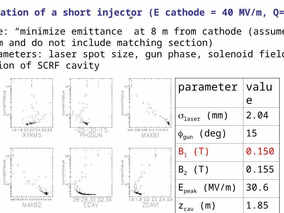
Optimization of a short injector (E cathode = 40 MV/m, Q=3.2 nC)
•Objective: “minimize emittance” at 8 m from cathode (assume round beam and do not include matching section)•Free parameters: laser spot size, gun phase, solenoid fields, E-fieldand location of SCRF cavity
parameter value
laser (mm) 2.04
gun (deg) 15
B1 (T) 0.150
B2 (T) 0.155
Epeak (MV/m) 30.6
zcav (m) 1.85
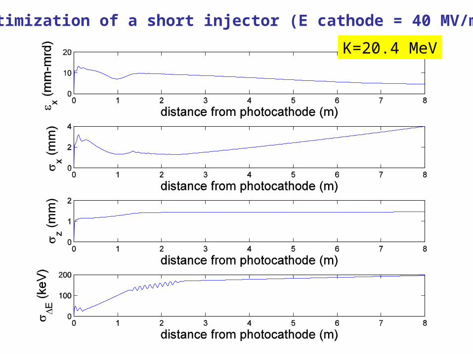
Optimization of a short injector (E cathode = 40 MV/m)
K=20.4 MeV
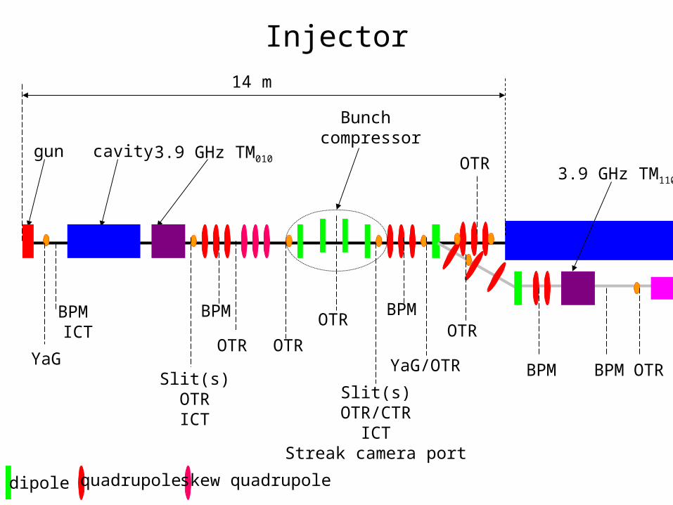
Injector
gun 3.9 GHz TM010cavity
Bunch compressor
3.9 GHz TM110
BPM BPM
Slit(s)OTRICT
OTR
Slit(s)OTR/CTR
ICTStreak camera port
YaG/OTR
OTR
BPM BPM
OTR
OTR
OTRYaG
BPM ICT
14 m
dipole quadrupole
OTR
skew quadrupole
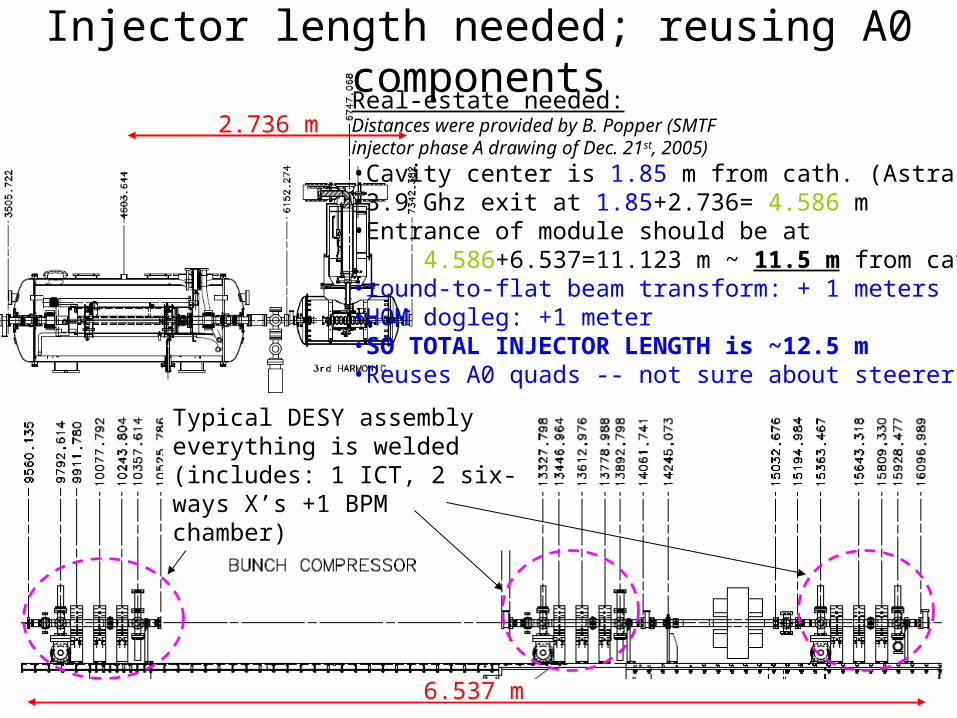
2.736 m
6.537 m
Real-estate needed:Distances were provided by B. Popper (SMTF injector phase A drawing of Dec. 21st, 2005)
•Cavity center is 1.85 m from cath. (Astra sim.)•3.9 Ghz exit at 1.85+2.736= 4.586 m •Entrance of module should be at 4.586+6.537=11.123 m ~ 11.5 m from cath.•round-to-flat beam transform: + 1 meters•HOM dogleg: +1 meter•SO TOTAL INJECTOR LENGTH is ~12.5 m•Reuses A0 quads -- not sure about steerers
Injector length needed; reusing A0 components
Typical DESY assemblyeverything is welded(includes: 1 ICT, 2 six-ways X’s +1 BPM chamber)
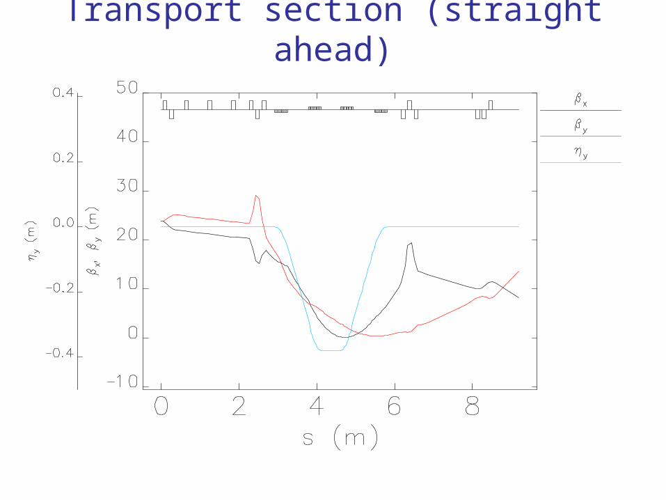
Transport section (straight ahead)
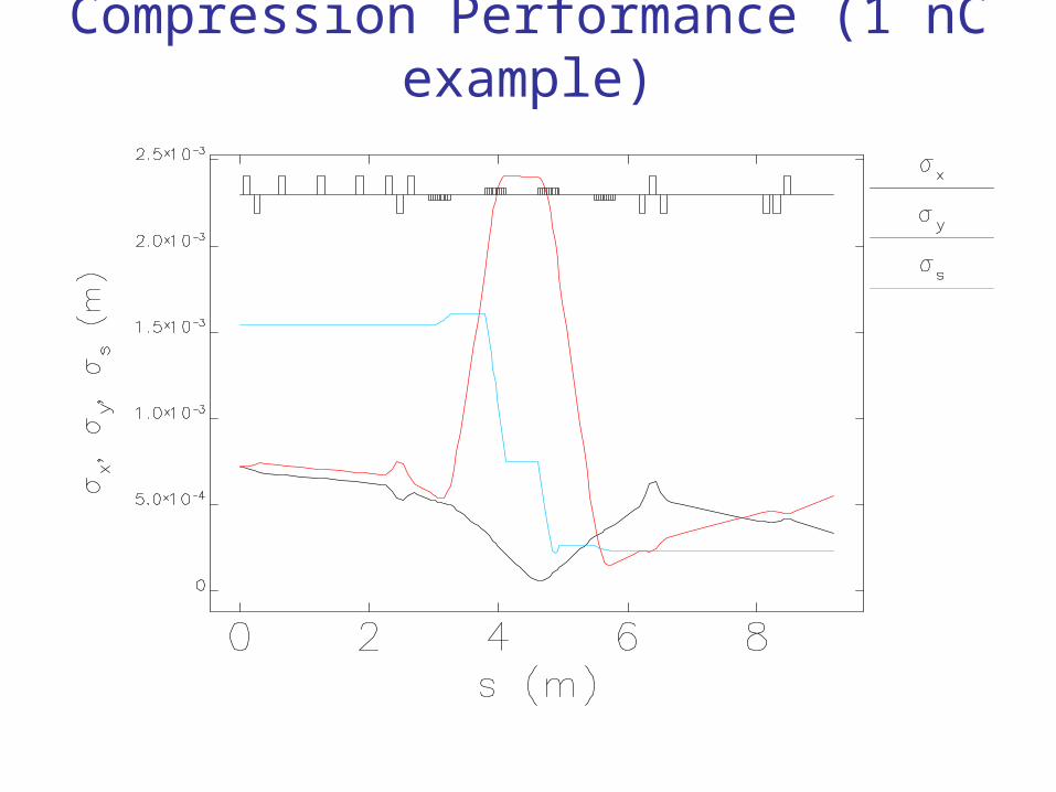
Compression Performance (1 nC example)
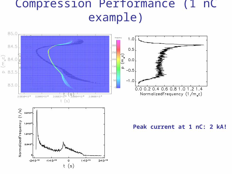
Compression Performance (1 nC example)
Peak current at 1 nC: 2 kA!
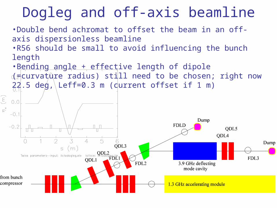
Dogleg and off-axis beamline•Double bend achromat to offset the beam in an off-axis dispersionless beamline•R56 should be small to avoid influencing the bunch length•Bending angle + effective length of dipole (=curvature radius) still need to be chosen; right now 22.5 deg, Leff=0.3 m (current offset if 1 m)
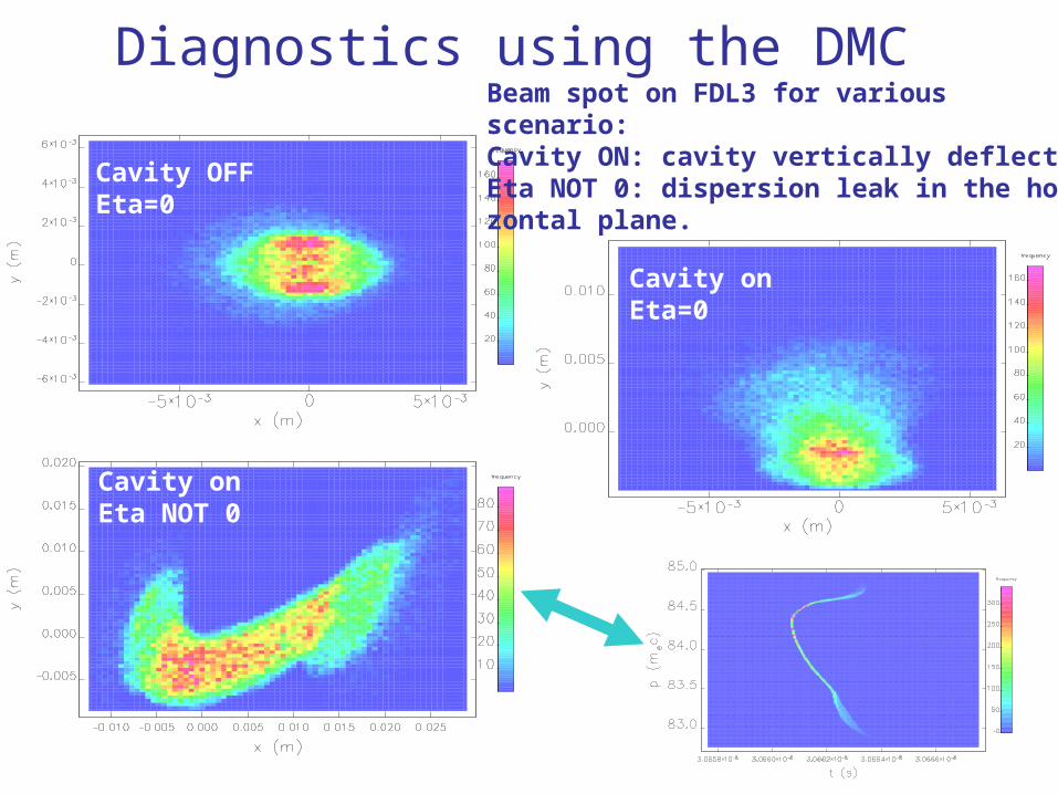
Diagnostics using the DMC
Cavity OFFEta=0
Cavity onEta NOT 0
Cavity onEta=0
Beam spot on FDL3 for various scenario:Cavity ON: cavity vertically deflectingEta NOT 0: dispersion leak in the hori-zontal plane.
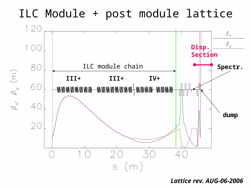
ILC module chain
III+ III+ IV+
Spectr.
dump
ILC Module + post module lattice
Disp. Section
Lattice rev. AUG-06-2006
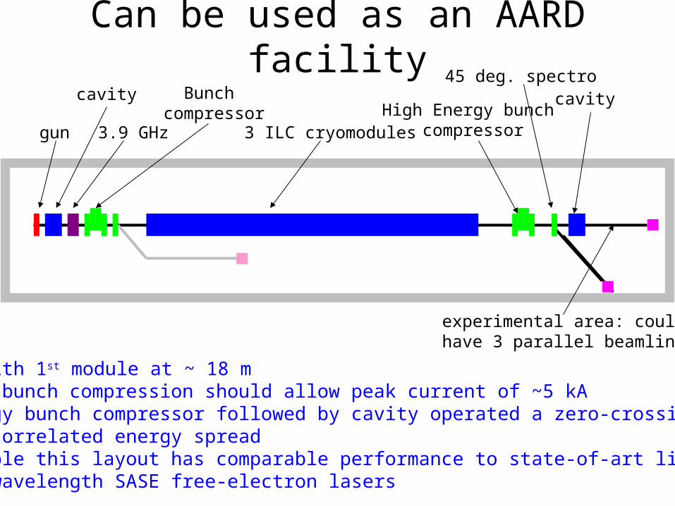
•Example with 1st module at ~ 18 m•Two stage bunch compression should allow peak current of ~5 kA •High energy bunch compressor followed by cavity operated a zero-crossing to remove correlated energy spread •In principle this layout has comparable performance to state-of-art linac-driver for short wavelength SASE free-electron lasers
gun 3.9 GHz
cavity Bunch compressor
3 ILC cryomodules
45 deg. spectro
High Energy bunch compressor
cavity
experimental area: could have 3 parallel beamline
Can be used as an AARD facility
•Finally all parties agreed on a possible layout at ILCTA
•Preliminary “look at” indicate no show stopper•Layout fit building, •Head room for upgrade (e.g. new gun location)
•Immediate work if focused on ILC-type applications, and simulation of related experiment (e.g. wakefield studies will be performed)
•The facility is “good-enough” to support an advanced R&D program
•First parasitically to ILC-related studies•Then dedicated to AARD with addition of new hall…
Summary & on-going work