Embed Size (px)
Citation preview
Location-based augmented reality on mobile phones
Remi Paucher and Matthew TurkComputer Science Department
University of California, Santa [email protected] | [email protected]
Abstract
The computational capability of mobile phones has beenrapidly increasing, to the point where augmented reality hasbecome feasible on cell phones. We present an approach toindoor localization and pose estimation in order to supportaugmented reality applications on a mobile phone platform.Using the embedded camera, the application localizes thedevice in a familiar environment and determines its orien-tation. Once the 6 DOF pose is determined, 3D virtual ob-jects from a database can be projected into the image anddisplayed for the mobile user. Off-line data acquisition con-sists of acquiring images at different locations in the envi-ronment. The online pose estimation is done by a feature-based matching between the cell phone image and an imageselected from the precomputed database using the phone’ssensors (accelerometer and magnetometer).
The application enables the user both to visualize vir-tual objects in the camera image and to localize the user ina familiar environment. We describe in detail the processof building the database and the pose estimation algorithmused on the mobile phone. We evaluate the algorithm per-formance as well as its accuracy in terms of reprojectiondistance of the 3D virtual objects in the cell phone image.
1. IntroductionThere have been many augmented reality systems using
various approaches for visual augmentation of the scene.Most of these methods fall into one of two categories:pose computation and object recognition. Many in the ARcommunity use object recognition to provide informationabout the recognizable objects viewed by the user. How-ever this approach works only if the user is looking at spe-cific known objects; it does not support augmented realitywhen there are no special objects in the scene. A more flex-ible approach is to determine the 6 DOF pose of the sensor,which enables the projection of any 3D virtual object froma database into the image the user is viewing at any locationin the 3D scene.
Our work uses an approach of this type, computing thesensor pose in an indoor environment and augmenting thescene by projecting 3D information into the image. Amongmany images of the environment taken at different locationsin the environment offline (creating a local database for usein the AR system), the algorithm selects the database im-age which is the most similar to the live cell phone image.The next step is to match the two images to find point cor-respondences, based on features extracted in both images.Then the pose between the two images can be computed sothat the position and the orientation of the cell phone cam-era can be known. 3D virtual objects from the database arethen projected in the image according to the computed poseas depicted in Figure 1.
Using mobile phones for augmented reality has both ad-vantages and drawbacks. First, cell phones with cameras arebecoming ubiquitous, so this is the most convenient plat-form on which to do augmented reality. AR applicationscan also benefit from cell phone sensors such as accelerom-eters and magnetometers, which can improve the quality ofaugmented reality and facilitate user tracking. However, de-spite rapid advances in mobile phones as a computing plat-form, their performance for real-time imaging applicationsis still very limited. Their computation power is equivalentto that of a typical computer perhaps ten years ago. Theyalso have relatively slow memory access and a small cache.Many do not support floating-point numbers natively, mak-ing some computations quite slow.
Many applications tracking cell phone position and ori-entation send data to a remote computer that does the com-putations and sends back the results to the mobile device.This approach is not well adapted to augmented reality ap-plications because of bandwidth limitations and the over-head and additional power consumption of data communi-cation. For these reasons, we chose in this work to do all thecomputation on the mobile device. Considering the trend incell phone computation power, it will most likely be feasi-ble to develop real-time AR applications processed locallyin the near future.
This work aims at showing the feasibility of doing indoor

Figure 1. Application overview. The database contains several im-ages taken at different locations (the green dots) in the indoor en-vironment (blue blob). The arrows are the optical axes and theangles represent fields of view. The pose (translation T and ro-tation R) between the cell phone image (bold blue lines) and adatabase image is computed by image matching. Then the 3D vir-tual objects (represented by yellow cubes) are projected into thecell phone image. Here, only one virtual object is seen by the cellphone.
localization and augmented reality on the fly using only thecell phone’s sensors and processing. Such a system couldbe used, for example, in a museum by visitors, to view tourdirections and information about pieces of art when point-ing their phones at them.
The paper is organized as follows: In Section 2 we dis-cuss the related work. Section 3 will describe the pre-processing steps to learn the environment and the databasebuilding process. In Section 4 we will present how the addi-tional cell phone sensors help in pose estimation. Our algo-rithms for image matching and pose computation on the cellphone side will be described in Section 5, and our resultsare presented in Section 6. We conclude with a discussionon the results and further work.
2. Related work
Early localization systems used radio signals to deter-mine the user location and relied on a remote server [8] [11].These systems came with a significant infrastructure cost.
Much work has been done in the robotics community onlocalization [18] [14] [6] [17]. However, the robots usu-ally have fewer degrees of freedom, and much of the workrelies on landmarks. Also many of these systems do notprovide metric localization, because they do not deal with a3D model.
The augmented reality community often uses markers inthe environment because of the low computation power re-
quirements and their robustness [16] [15] [19]. Some worksuse them for localization [9] [10] [13]. However this is aninvasive solution since objects have to be tagged with thesecodes. Our approach does not require one to place any ad-ditional content in the environment. Much of the work inthe AR community uses object detection and recognitiontechniques rather than pose estimation.
SLAM approaches like [5] enable to localize the user bybuilding a map on-the-fly. However this kind of approach ismore appropriate to small unfamiliar workspaces and pro-vide much less precise maps.
6 DOF pose estimation has become possible on mo-bile phones due to the increasing computation power avail-able on these devices [20]. However, for large and uncon-strained environments pose estimation may be infeasibledue to the difficulties of efficiently matching a given imagewith a database of information about the complete environ-ment. In this work, we consider only database images thatare likely to be seen by the camera at its estimated posi-tion. Therefore the approach is easily scalable to wide ar-eas, unlike approaches that search the whole database [12].Arth et al. [1] worked on the problem of localization oncell phones by feature matching, using a potential visibleset (PVS) approach to search only relevant images. Theirmethod searches all the point sets adjacent to the camera’slocation. The embedded sensors on today’s cell phones en-able us to go a step further and produce an estimate of thecamera pose before any processing of the image.
3. Database buildingThe first step in the application is to acquire data in ad-
vance about the environment; e.g., to go through a museumand create a database that will be used subsequently by ARapplications in the building. This involves carrying a cam-era rig through the space and preprocessing this data on ahost computer. The data comprises images of the environ-ment taken at different locations. For each image, we storethe pose of the camera (its absolute rotation and position)and its intrinsic parameters. Then we extract SURF fea-tures [2] in each of the images and store their positions inthe image as well as their descriptors. On the cell phone ap-plication, we want the user localization to be metric; this re-quires us to have metric information in the database. There-fore we use a stereo camera for the database images, whichproduces the depth for each pixel of the image. As a result,we also store the 3D position of the features in each image.For a reason to be explained below, we also store the 3Dposition of the center of the images.
Among all the detected SURF features, we have tochoose the most robust ones; i.e., those that are likely tobe detected in the cell phone image and be close to the newfeature in terms of descriptor similarity. In order to do that,we track each feature over several frames and keep only the
ones that were successfully tracked over all the frames. Thecriterion to keep a feature from one frame to the next oneis that the feature position remains close to its previous po-sition and that the distance between the descriptors is shortenough. In practice, we track the SURF features while thestereo camera remains still. This eliminates many of thefeatures detected because of the noise in the image.
4. Cell phone sensors and pose estimation
Once the database has been collected and processed, theindoor environment is ready to support location-based ARon the mobile phone. As we will see in Section 5, havinga coarse estimate of the pose makes the image retrieval stepeasier and accelerates the pose estimation algorithm. In thiswork, we used the N97 phone from Nokia. It has severalsensors to help us with the pose estimation such as GPS, anaccelerometer, a magnetometer and a rotation sensor.
First, when considering cell phone pose estimation, wehave to define an absolute coordinate system. As a right-handed cartesian coordinate system, we chose the system(−→E ,−→g ,
−→N ), where
−→E is East, −→g gravity and
−→N North.
In this section, we will show how to use the cell phonesensors to produce a camera pose estimation in the definedcoordinate system.
4.1. Position
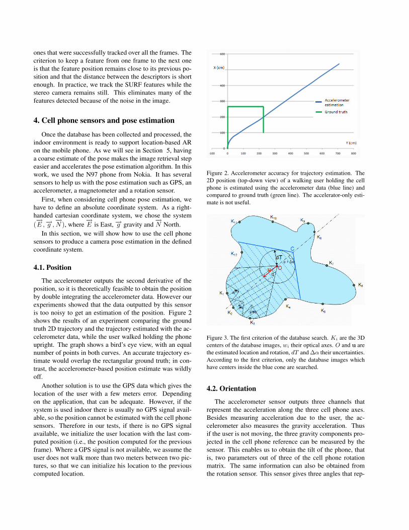
The accelerometer outputs the second derivative of theposition, so it is theoretically feasible to obtain the positionby double integrating the accelerometer data. However ourexperiments showed that the data outputted by this sensoris too noisy to get an estimation of the position. Figure 2shows the results of an experiment comparing the groundtruth 2D trajectory and the trajectory estimated with the ac-celerometer data, while the user walked holding the phoneupright. The graph shows a bird’s eye view, with an equalnumber of points in both curves. An accurate trajectory es-timate would overlap the rectangular ground truth; in con-trast, the accelerometer-based position estimate was wildlyoff.
Another solution is to use the GPS data which gives thelocation of the user with a few meters error. Dependingon the application, that can be adequate. However, if thesystem is used indoor there is usually no GPS signal avail-able, so the position cannot be estimated with the cell phonesensors. Therefore in our tests, if there is no GPS signalavailable, we initialize the user location with the last com-puted position (i.e., the position computed for the previousframe). Where a GPS signal is not available, we assume theuser does not walk more than two meters between two pic-tures, so that we can initialize his location to the previouscomputed location.
Figure 2. Accelerometer accuracy for trajectory estimation. The2D position (top-down view) of a walking user holding the cellphone is estimated using the accelerometer data (blue line) andcompared to ground truth (green line). The accelerator-only esti-mate is not useful.
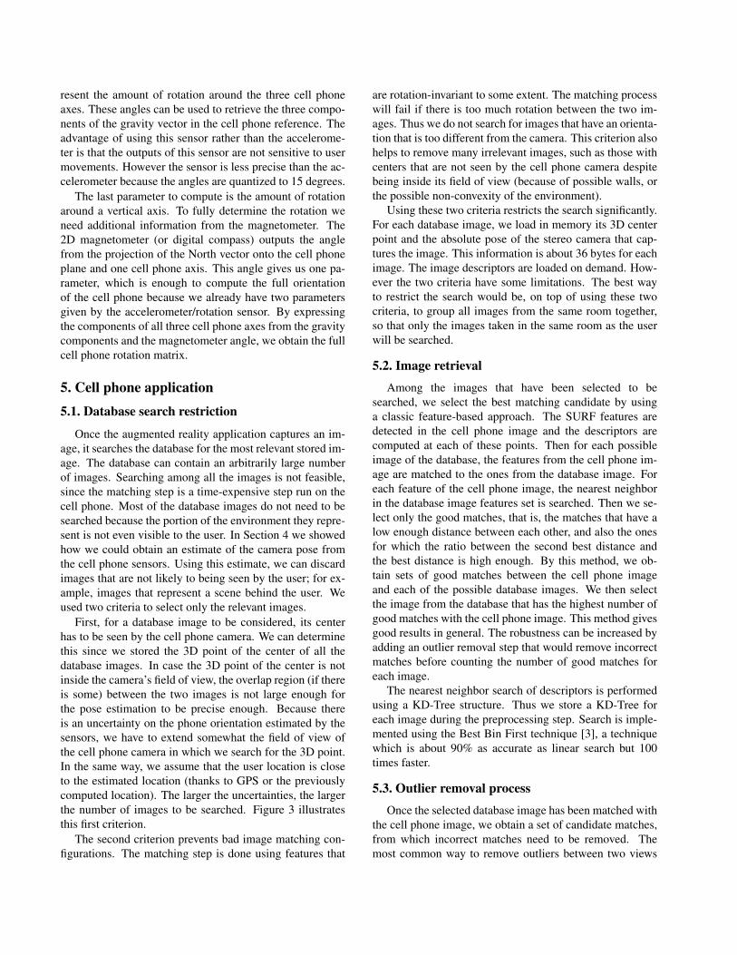
Figure 3. The first criterion of the database search. Ki are the 3Dcenters of the database images, wi their optical axes. O and u arethe estimated location and rotation, dT and ∆α their uncertainties.According to the first criterion, only the database images whichhave centers inside the blue cone are searched.
4.2. Orientation
The accelerometer sensor outputs three channels thatrepresent the acceleration along the three cell phone axes.Besides measuring acceleration due to the user, the ac-celerometer also measures the gravity acceleration. Thusif the user is not moving, the three gravity components pro-jected in the cell phone reference can be measured by thesensor. This enables us to obtain the tilt of the phone, thatis, two parameters out of three of the cell phone rotationmatrix. The same information can also be obtained fromthe rotation sensor. This sensor gives three angles that rep-
resent the amount of rotation around the three cell phoneaxes. These angles can be used to retrieve the three compo-nents of the gravity vector in the cell phone reference. Theadvantage of using this sensor rather than the accelerome-ter is that the outputs of this sensor are not sensitive to usermovements. However the sensor is less precise than the ac-celerometer because the angles are quantized to 15 degrees.
The last parameter to compute is the amount of rotationaround a vertical axis. To fully determine the rotation weneed additional information from the magnetometer. The2D magnetometer (or digital compass) outputs the anglefrom the projection of the North vector onto the cell phoneplane and one cell phone axis. This angle gives us one pa-rameter, which is enough to compute the full orientationof the cell phone because we already have two parametersgiven by the accelerometer/rotation sensor. By expressingthe components of all three cell phone axes from the gravitycomponents and the magnetometer angle, we obtain the fullcell phone rotation matrix.
5. Cell phone application
5.1. Database search restriction
Once the augmented reality application captures an im-age, it searches the database for the most relevant stored im-age. The database can contain an arbitrarily large numberof images. Searching among all the images is not feasible,since the matching step is a time-expensive step run on thecell phone. Most of the database images do not need to besearched because the portion of the environment they repre-sent is not even visible to the user. In Section 4 we showedhow we could obtain an estimate of the camera pose fromthe cell phone sensors. Using this estimate, we can discardimages that are not likely to being seen by the user; for ex-ample, images that represent a scene behind the user. Weused two criteria to select only the relevant images.
First, for a database image to be considered, its centerhas to be seen by the cell phone camera. We can determinethis since we stored the 3D point of the center of all thedatabase images. In case the 3D point of the center is notinside the camera’s field of view, the overlap region (if thereis some) between the two images is not large enough forthe pose estimation to be precise enough. Because thereis an uncertainty on the phone orientation estimated by thesensors, we have to extend somewhat the field of view ofthe cell phone camera in which we search for the 3D point.In the same way, we assume that the user location is closeto the estimated location (thanks to GPS or the previouslycomputed location). The larger the uncertainties, the largerthe number of images to be searched. Figure 3 illustratesthis first criterion.
The second criterion prevents bad image matching con-figurations. The matching step is done using features that
are rotation-invariant to some extent. The matching processwill fail if there is too much rotation between the two im-ages. Thus we do not search for images that have an orienta-tion that is too different from the camera. This criterion alsohelps to remove many irrelevant images, such as those withcenters that are not seen by the cell phone camera despitebeing inside its field of view (because of possible walls, orthe possible non-convexity of the environment).
Using these two criteria restricts the search significantly.For each database image, we load in memory its 3D centerpoint and the absolute pose of the stereo camera that cap-tures the image. This information is about 36 bytes for eachimage. The image descriptors are loaded on demand. How-ever the two criteria have some limitations. The best wayto restrict the search would be, on top of using these twocriteria, to group all images from the same room together,so that only the images taken in the same room as the userwill be searched.
5.2. Image retrieval
Among the images that have been selected to besearched, we select the best matching candidate by usinga classic feature-based approach. The SURF features aredetected in the cell phone image and the descriptors arecomputed at each of these points. Then for each possibleimage of the database, the features from the cell phone im-age are matched to the ones from the database image. Foreach feature of the cell phone image, the nearest neighborin the database image features set is searched. Then we se-lect only the good matches, that is, the matches that have alow enough distance between each other, and also the onesfor which the ratio between the second best distance andthe best distance is high enough. By this method, we ob-tain sets of good matches between the cell phone imageand each of the possible database images. We then selectthe image from the database that has the highest number ofgood matches with the cell phone image. This method givesgood results in general. The robustness can be increased byadding an outlier removal step that would remove incorrectmatches before counting the number of good matches foreach image.
The nearest neighbor search of descriptors is performedusing a KD-Tree structure. Thus we store a KD-Tree foreach image during the preprocessing step. Search is imple-mented using the Best Bin First technique [3], a techniquewhich is about 90% as accurate as linear search but 100times faster.
5.3. Outlier removal process
Once the selected database image has been matched withthe cell phone image, we obtain a set of candidate matches,from which incorrect matches need to be removed. Themost common way to remove outliers between two views
is using a RANSAC [4] loop computing the fundamentalmatrix at each iteration. Depending on the algorithm used,5, 7 or 8 points are needed to compute the fundamental ma-trix. We considered that algorithms that need fewer than 8points are too time-consuming, even if they are more pre-cise. However the 8-point algorithm uses a linear criterionthat gives very poor results in the presence of noise, whichis why using it inside a RANSAC loop gives unusable re-sults. This leads both to discarding inliers and to acceptingoutliers. We cannot use this because the pose computationalgorithm is very sensitive to outliers, so it needs to dealonly with inliers. Therefore we first remove the most obvi-ous wrong matches by approximating the transformation asplanar. Thus we first fit a homography between the two setsof points using the Least Median of Square algorithm. Thenthe points that lie too far from their image by the homogra-phy are considered as outliers. In other words, only pointsthat roughly satisfy a planar criterion are selected. The cho-sen threshold is of course high, so that depth changes areallowed. This step removes most of the outliers and is fastbecause it requires only four matches to estimate the ho-mography at each iteration. We can then use the 8-pointalgorithm combined with RANSAC to remove the final out-liers. Since matches have been filtered before this step, weneed only a small number of RANSAC iterations.
The 8-point algorithm works well to remove outliers dur-ing the last step of the outlier removal, but because of itspoor accuracy it fails to give a precise estimate of the fun-damental matrix, even when refining the estimate using allof the inliers. It can only be used to remove outliers but notto estimate the pose.
We also considered removing the outliers using the 3Dpoints coordinates to estimate the 6 DOF pose from threepoints [7] in a RANSAC loop. However this method is morecomplex because it requires solving polynomial equationswhich lead to up to four solutions. We chose not to use itbecause we obtained similar results with our method in lesstime.
5.4. Pose computation
At this step we have a set of presumably correct matchesbetween the cell phone and the database images, which en-ables us to compute the relative pose between the two im-ages. Given 2D-3D matches, we have to find the translationand the rotation between the two cameras. In the following,ci and di are 2D points in the cell phone and the databaseimages respectively, Xi is a 3D point in the database systemcoordinates, and Kc and Kd are the calibration matrices ofthe cell phone and the stereo camera, respectively. In thissection, we propose two different methods to estimate thepose.
5.4.1 Reprojection minimization
The final goal is that the projected virtual objects match theimage content as close as possible. Therefore, the reprojec-tion error of the database 3D points in the cell phone imageis the most meaningful criterion to minimize. No matterwhich method we use, the final pose estimation step has tobe the minimization of this criterion:
minR,T
∑i
∥∥∥∥ Kc (RXi + T)(Kc (RXi + T))3
−(
ci
1
)∥∥∥∥2
The minimization is done using the Levenberg-Marquardt algorithm, over six parameters (three for the ro-tation and three for the translation). Of course the pose hasto be well estimated before doing this local minimization.In our tests if the number of matches is high, the estimationdoes not have to be very precise for the global minimum tobe found. A pose estimation using the 8-point algorithm isadequate. The problem is now to initialize the pose beforedoing the final minimization.
5.4.2 First initialization method
Because the 8-point algorithm does not give good results,we propose an alternative algorithm to initialize the pose.We have an estimate (R) of the rotation given by the cellphone sensors. We can still minimize the sum of squaresas in the 8-point algorithm, but only over the translationparameters, by setting the rotation equal to the sensors es-timate. The translation can only be estimated up to scalewhen using the 2D points, so the minimization is done ononly two parameters. Plus we do not have the essential ma-trix constraints problems from the 8-point algorithm any-more, because we minimize directly over pose parameters.The × symbol stands for cross product.
minT‖T‖=1
∑i
(T.(ci × Rdi
))2
The resolution is done using an SVD decomposition on a3×3 matrix, which is very fast. This is precise because therotation is well estimated by the cell phone sensors. Thissame method can be used inside a RANSAC loop to re-move the outliers; it requires only two points to determinethe translation and is very fast. We have tested this outlierremoval technique, but it does not remove all the outliers,and performs worse in general than the homography fit.
Next we refine the pose by minimizing the Sampson cri-terion, which is more meaningful than a linear criterion:
minF
∑i
( (ci
T Fdi
)2(Fdi)
21 + (Fdi)
22 + (FT ci)
21 + (FT ci)
22
)
where the fundamental matrix F is expressed as a functionof the pose parameters: F = Kd
−T [T]×RKc−1.
In this minimization, the translation is represented inspherical coordinates and the rotation via the angle/axis rep-resentation. The minimization is thus done over five param-eters thanks to the Levenberg-Marcquardt algorithm. Thisminimization is of course local, so it needs a good initial-ization. We initialize it with the pose estimation from theprevious algorithm.
At this point, the translation has only been estimated upto scale. To obtain the translation norm, we use point depthsfrom the stereo camera (database). For each match, we cancompute the translation norm value using geometric consid-erations in triangles. Among all these values for the trans-lation norm, selecting the median is the best choice to besensitive to noisy matches as little as possible.
5.4.3 Second initialization method
The previous method provides an accurate 6 DOF pose es-timation. However it is rather slow because it involves anLM minimization. We propose an alternative method to ini-tialize the pose. Let us consider this minimization (R is theestimation of the orientation using the cell phone sensors):
minT
∑i
∥∥∥∥Kc
(RXi + T
)−(RXi + T
)3
(ci
1
)∥∥∥∥2
This criterion is the linearized version of the final crite-rion we want to minimize. Of course it is less meaningful,because it gives more importance to the points that have ahigh depth and to the ones that lie far from the image cen-ter. But it has the advantage of being much more easily andquickly minimized. Because the rotation is estimated bythe cell phone sensors, the minimization is done over onlythe three translation parameters. The derivatives of this ex-pression are linear, so it requires only one 3×3 matrix SVDdecomposition to compute the translation parameters.
This method is faster than the previous one because ituses only one SVD decomposition. In our experiments it isslightly more robust for finding the global minimum.
6. Results and performance6.1. Augmented reality
In our tests, we picked in the 3D model some 3D pointsthat correspond to something remarkable in the environ-ment. All the 3D virtual objects we used for the AR ex-periments are planar rectangles. Although any 3D objectcan be inserted in the database, rectangles make it easier forvisualization and error measuring. We built a database ofimages in a lab environment and picked rectangles in the 3Dmodel. After the user points the cell phone in the direction
of these objects, the pose between the cell phone cameraand the database image is computed. The visible objectsare then projected into the cell phone image according tothe pose estimation. Figure 4 shows the augmented picture;the reprojection error is about four pixels for a 640×480image. As we can see, the final minimization is a manda-tory step. As always, there is a trade-off between qualityand time. The bigger the images, the more features will beextracted, so the precision will be better but the algorithmwill be slower.
We can have even better results when the rotation islower. In the previous test, the rotation was about 45 de-grees. Figure 6 shows a result where rotation is close to 0degrees and the error is only about two pixels.
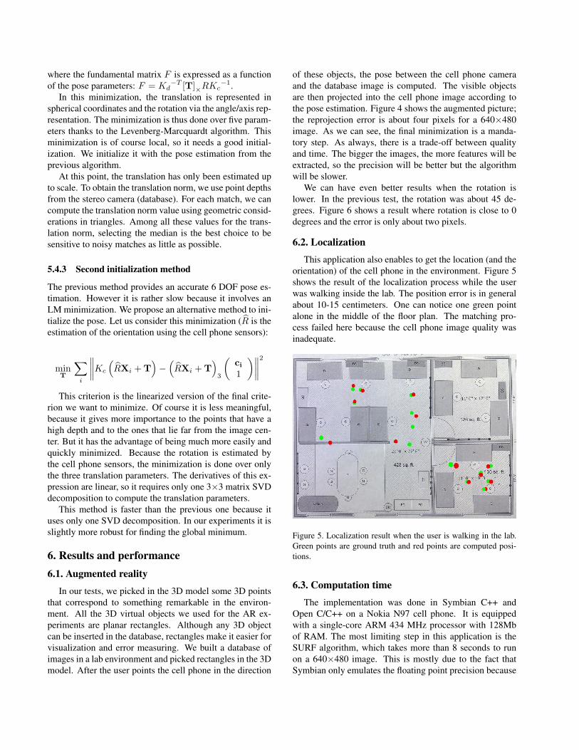
6.2. Localization
This application also enables to get the location (and theorientation) of the cell phone in the environment. Figure 5shows the result of the localization process while the userwas walking inside the lab. The position error is in generalabout 10-15 centimeters. One can notice one green pointalone in the middle of the floor plan. The matching pro-cess failed here because the cell phone image quality wasinadequate.
Figure 5. Localization result when the user is walking in the lab.Green points are ground truth and red points are computed posi-tions.
6.3. Computation time
The implementation was done in Symbian C++ andOpen C/C++ on a Nokia N97 cell phone. It is equippedwith a single-core ARM 434 MHz processor with 128Mbof RAM. The most limiting step in this application is theSURF algorithm, which takes more than 8 seconds to runon a 640×480 image. This is mostly due to the fact thatSymbian only emulates the floating point precision because
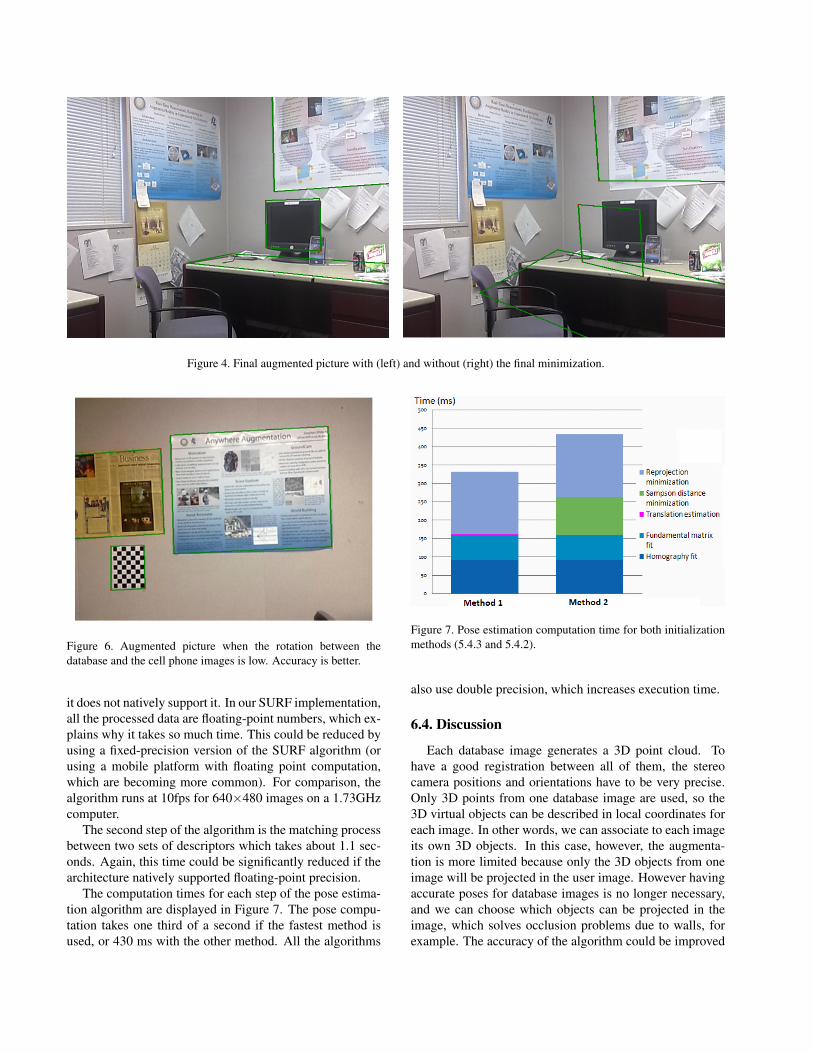
Figure 4. Final augmented picture with (left) and without (right) the final minimization.
Figure 6. Augmented picture when the rotation between thedatabase and the cell phone images is low. Accuracy is better.
it does not natively support it. In our SURF implementation,all the processed data are floating-point numbers, which ex-plains why it takes so much time. This could be reduced byusing a fixed-precision version of the SURF algorithm (orusing a mobile platform with floating point computation,which are becoming more common). For comparison, thealgorithm runs at 10fps for 640×480 images on a 1.73GHzcomputer.
The second step of the algorithm is the matching processbetween two sets of descriptors which takes about 1.1 sec-onds. Again, this time could be significantly reduced if thearchitecture natively supported floating-point precision.
The computation times for each step of the pose estima-tion algorithm are displayed in Figure 7. The pose compu-tation takes one third of a second if the fastest method isused, or 430 ms with the other method. All the algorithms
Figure 7. Pose estimation computation time for both initializationmethods (5.4.3 and 5.4.2).
also use double precision, which increases execution time.
6.4. Discussion
Each database image generates a 3D point cloud. Tohave a good registration between all of them, the stereocamera positions and orientations have to be very precise.Only 3D points from one database image are used, so the3D virtual objects can be described in local coordinates foreach image. In other words, we can associate to each imageits own 3D objects. In this case, however, the augmenta-tion is more limited because only the 3D objects from oneimage will be projected in the user image. However havingaccurate poses for database images is no longer necessary,and we can choose which objects can be projected in theimage, which solves occlusion problems due to walls, forexample. The accuracy of the algorithm could be improved
if the quality of the images was improved. The stereo cam-era is very sensitive to brightness and reflective surfaces.To capture good quality images with the stereo camera, theuser has to choose manually the parameters (gain, exposure,etc.) that differ for each image. The same goes for the cellphone images. With Symbian APIs, instead of capturing a640×480 image, the camera actually captures a 480×360image that is rescaled to 640×480. Thus a lot of precisionis lost to the detriment of the matching step. Because ofthis issue, there is also a large uncertainty in the cell phonecalibration parameters that we obtained thanks to Zhang’salgorithm [21].
7. Conclusion and further workIn this paper we showed that augmented reality using 6
DOF tracking is feasible on mobile phones. The cell phoneis tracked with a precision of about 10-15cm, which trans-lates to error in the augmented images of about a few pixels.For further work, we would like to improve the translationinitialization before the final minimization. That could besolved by increasing the frame rate, so that the user move-ment between two frames would be low enough to be ableto initialize the position with the last user position withoutuser speed limitation. Techniques like optical flow or track-ing could then be used to avoid searching the database at ev-ery frame. Because there is no location estimation from thesensors, the user has to start the application at a known loca-tion; otherwise the application has to search all the databaseimages, which is not feasible on the cell phone. This taskwould be very suitable for a remote server, because thesearch can be entirely parallelized. This would be helpfulto initialize the user location. In addition, we may considerswitching from the SURF algorithm to a more lightweightstate-of-the-art feature, such as in [20] where real time per-formance is achieved. Finally, porting the code to an ar-chitecture that would have native support for floating-pointnumbers like the Nokia N900 mobile phone would improvethe frame rate drastically.
References[1] C. Arth, D. Wagner, et al. Wide area localization on mobile
phones. In Proc. IEEE International Symposium on Mixedand Augmented Reality, pp 73–82, Orlando, FL, 2009.
[2] H. Bay, T. Tuytelaars, et al. Surf: Speeded up robust features.In European Conference on Computer Vision, pp 404–417,2006.
[3] J. S. Beis and D. G. Lowe. Shape indexing using approx-imate nearest-neighbour search in high-dimensional spaces.In Proc. IEEE Conf. Comp. Vision Patt. Recog, pp 1000–1006, 1997.
[4] M. A. Fischler and R. C. Bolles. Random sample consen-sus: a paradigm for model fitting with applications to imageanalysis and automated cartography. pp 726–740, 1987.
[5] P. Gemeiner, A. Davison, et al. Improving localization ro-bustness in monocular SLAM using a high-speed camera. InProc. of Robotics: Science and Systems IV, June 2008.
[6] J.-S. Gutmann, W. Burgard, et al. An experimental com-parison of localization methods. In Proc. of the IEEE/RSJInternational Conference on Intelligent Robots and Systems,1998.
[7] R. M. Haralick, C. Lee, et al. Analysis and solutions of thethree point perspective pose estimation problem. Tr, 1991.
[8] A. Harter, A. Hopper, et al. The anatomy of a context-awareapplication. In Proceedings of the 5th Annual ACM/IEEE In-ternational Conference on Mobile Computing and Network-ing, pp 59–68, 1999.
[9] M. Kalkusch, T. Lidy, et al. Structured visual markers forindoor pathfinding. In Proceedings of the First IEEE Inter-national Workshop on ARToolKit. IEEE, 2002.
[10] L. Naimark and E. Foxlin. Circular data matrix fiducialsystem and robust image processing for a wearable vision-inertial self-tracker. In Proceedings of the 1st Interna-tional Symposium on Mixed and Augmented Reality, page 27,Darmstadt, Germany, 2002.
[11] N. B. Priyantha, A. Chakraborty, et al. The Cricket Location-Support System. In 6th ACM MOBICOM, Boston, MA, Au-gust 2000.
[12] N. Ravi, P. Shankar, et al. Indoor localization using cameraphones. In Proceedings of the Seventh IEEE Workshop onMobile Computing Systems & Applications, pp 1–7, 2006.
[13] G. Reitmayr and T. W. Drummond. Initialisation for visualtracking in urban environments. In Proceedings of the 20076th IEEE and ACM International Symposium on Mixed andAugmented Reality, pp 1–9, 2007.
[14] T. Rofer and M. Jungel. Vision-based fast and reactivemonte-carlo localization. In IEEE International Conferenceon Robotics and Automation, pp 856–861, 2003.
[15] M. Rohs. Real-world interaction with camera-phones. In 2ndInternational Symposium on Ubiquitous Computing Systems,pp 74–89, Tokyo, Japan, Nov. 2004.
[16] M. Rohs and P. Zweifel. A conceptual framework for cameraphone-based interaction techniques. In Proc. Pervasive, pp171–189, 2005.
[17] R. Sim and G. Dudek. Mobile robot localization fromlearned landmarks. In Proceedings of IEEE/RSJ Conferenceon Intelligent Robots and Systems (IROS), 1998.
[18] S. Thrun, D. Fox, et al. Robust monte carlo localizationfor mobile robots. Artificial Intelligence, 128(1-2):99–141,2001.
[19] E. Toye, R. Sharp, et al. Using smart phones to access site-specific services. IEEE Pervasive Computing, 4(2):60–66,2005.
[20] D. Wagner, G. Reitmayr, et al. Pose tracking from naturalfeatures on mobile phones. In ISMAR ’08: Proc. IEEE/ACMInternational Symposium on Mixed and Augmented Reality,pp 125–134, 2008.
[21] Z. Zhang. A flexible new technique for camera calibration.IEEE Transactions on Pattern Analysis and Machine Intelli-gence, 22:1330–1334, 1998.


![State of Augmented Reality, Virtual Reality and Mixed Reality · State of Augmented Reality, Virtual Reality and Mixed Reality [Microsoft Hololen] [Ready Player One] Augmented Reality](https://img.pdfslide.us/doc/110x75/5f82ab6da2d89130b90d78c7/state-of-augmented-reality-virtual-reality-and-mixed-reality-state-of-augmented.jpg)