Embed Size (px)
Citation preview
Localized Corrosion and Fatigue Behavior of Ultra-Deep Drilling Alloys
4 March 2014
Office of Fossil Energy NETL-TRS-1-2014
Disclaimer This report was prepared as an account of work sponsored by an agency of the United States Government. Neither the United States Government nor any agency thereof, nor any of their employees, makes any warranty, express or implied, or assumes any legal liability or responsibility for the accuracy, completeness, or usefulness of any information, apparatus, product, or process disclosed, or represents that its use would not infringe privately owned rights. Reference therein to any specific commercial product, process, or service by trade name, trademark, manufacturer, or otherwise does not necessarily constitute or imply its endorsement, recommendation, or favoring by the United States Government or any agency thereof. The views and opinions of authors expressed therein do not necessarily state or reflect those of the United States Government or any agency thereof.
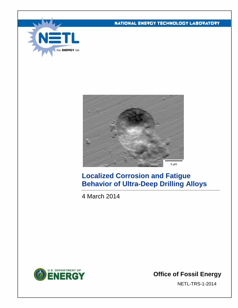
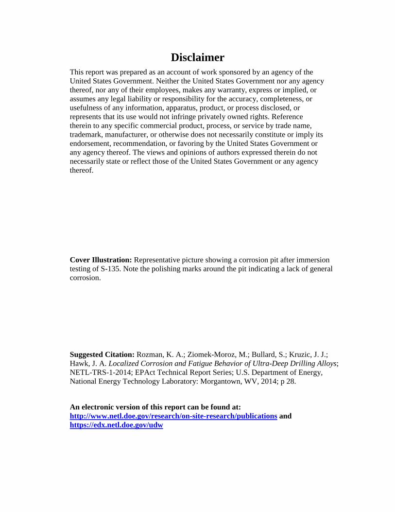
Cover Illustration: Representative picture showing a corrosion pit after immersion testing of S-135. Note the polishing marks around the pit indicating a lack of general corrosion.
Suggested Citation: Rozman, K. A.; Ziomek-Moroz, M.; Bullard, S.; Kruzic, J. J.; Hawk, J. A. Localized Corrosion and Fatigue Behavior of Ultra-Deep Drilling Alloys; NETL-TRS-1-2014; EPAct Technical Report Series; U.S. Department of Energy, National Energy Technology Laboratory: Morgantown, WV, 2014; p 28.
An electronic version of this report can be found at: http://www.netl.doe.gov/research/on-site-research/publications and https://edx.netl.doe.gov/udw
Localized Corrosion and Fatigue Behavior of Ultra-Deep Drilling Alloys
K. A. Rozman1,2, M. Ziomek-Moroz1, S. Bullard1, J. J. Kruzic1,2, J. A. Hawk1
1 U.S. Department of Energy, National Energy Technology Laboratory, 1450 Queen Ave SW, Albany, OR 97321
2 Oregon State University, Materials Science, School of Mechanical, Industrial, and Manufacturing Engineering, 204 Rogers Hall, Corvallis, OR 97331
NETL-TRS-1-2014
4 March 2014
NETL Contacts:
Jeffrey Hawk, Principal Investigator
Margaret Ziomek-Moroz, Principal Investigator
Kelly Rose, Technical Coordinator
George Guthrie, Focus Area Lead

This page intentionally left blank.

Localized Corrosion and Fatigue Behavior of Ultra-Deep Drilling Alloys
Table of Contents EXECUTIVE SUMMARY ...........................................................................................................1 1. INTRODUCTION ..................................................................................................................2 2. MATERIALS AND METHODS ..........................................................................................5
2.1 MATERIALS ...................................................................................................................5 2.2 IMMERSION TESTING .................................................................................................5 2.3 ELECTROCHEMICAL EXPERIMENTS ......................................................................6 2.4 FATIGUE EXPERIMENTS ............................................................................................7
3. RESULTS ...............................................................................................................................9 3.1 MATERIAL CHARACTERIZATION ...........................................................................9 3.2 CORROSION RESULTS ................................................................................................9 3.3 FATIGUE RESULTS ....................................................................................................11
4. DISCUSSION .......................................................................................................................15 5. CONCLUSIONS ..................................................................................................................18 6. REFERENCES .....................................................................................................................19
I
Localized Corrosion and Fatigue Behavior of Ultra-Deep Drilling Alloys
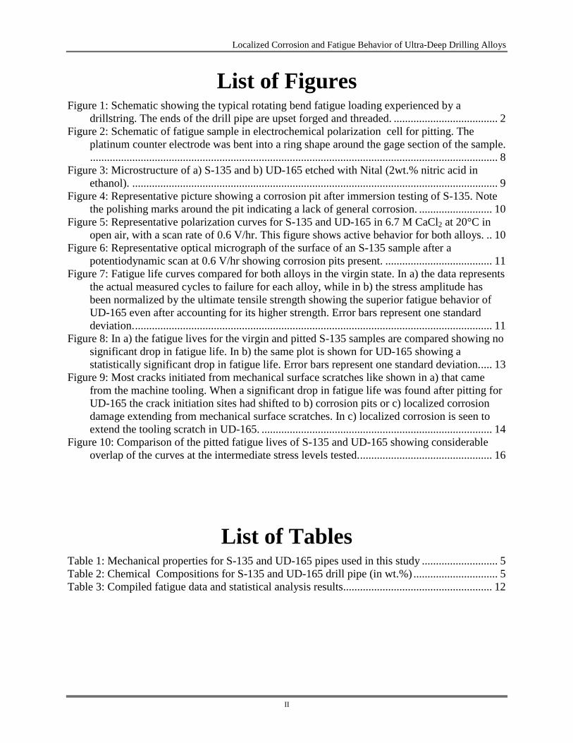
List of Figures Figure 1: Schematic showing the typical rotating bend fatigue loading experienced by a
drillstring. The ends of the drill pipe are upset forged and threaded. ..................................... 2 Figure 2: Schematic of fatigue sample in electrochemical polarization cell for pitting. The
platinum counter electrode was bent into a ring shape around the gage section of the sample. ................................................................................................................................................. 8
Figure 3: Microstructure of a) S-135 and b) UD-165 etched with Nital (2wt.% nitric acid in ethanol). .................................................................................................................................. 9
Figure 4: Representative picture showing a corrosion pit after immersion testing of S-135. Note the polishing marks around the pit indicating a lack of general corrosion. .......................... 10
Figure 5: Representative polarization curves for S-135 and UD-165 in 6.7 M CaCl2 at 20°C in open air, with a scan rate of 0.6 V/hr. This figure shows active behavior for both alloys. .. 10
Figure 6: Representative optical micrograph of the surface of an S-135 sample after a potentiodynamic scan at 0.6 V/hr showing corrosion pits present. ...................................... 11
Figure 7: Fatigue life curves compared for both alloys in the virgin state. In a) the data represents the actual measured cycles to failure for each alloy, while in b) the stress amplitude has been normalized by the ultimate tensile strength showing the superior fatigue behavior of UD-165 even after accounting for its higher strength. Error bars represent one standard deviation. ............................................................................................................................... 11
Figure 8: In a) the fatigue lives for the virgin and pitted S-135 samples are compared showing no significant drop in fatigue life. In b) the same plot is shown for UD-165 showing a statistically significant drop in fatigue life. Error bars represent one standard deviation. .... 13
Figure 9: Most cracks initiated from mechanical surface scratches like shown in a) that came from the machine tooling. When a significant drop in fatigue life was found after pitting for UD-165 the crack initiation sites had shifted to b) corrosion pits or c) localized corrosion damage extending from mechanical surface scratches. In c) localized corrosion is seen to extend the tooling scratch in UD-165. .................................................................................. 14
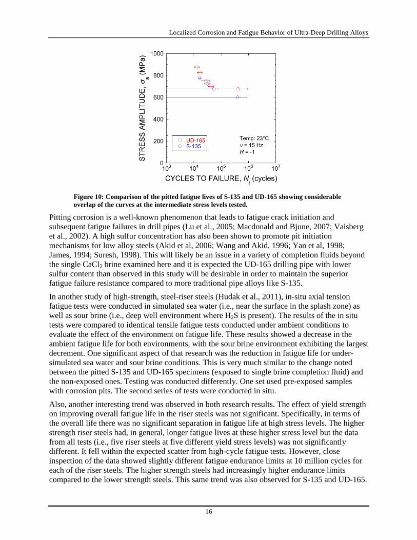
Figure 10: Comparison of the pitted fatigue lives of S-135 and UD-165 showing considerable overlap of the curves at the intermediate stress levels tested. ............................................... 16
List of Tables Table 1: Mechanical properties for S-135 and UD-165 pipes used in this study ........................... 5 Table 2: Chemical Compositions for S-135 and UD-165 drill pipe (in wt.%) .............................. 5 Table 3: Compiled fatigue data and statistical analysis results..................................................... 12
II
Localized Corrosion and Fatigue Behavior of Ultra-Deep Drilling Alloys
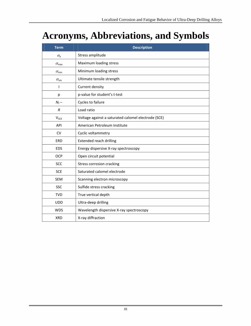
Acronyms, Abbreviations, and Symbols Term Description
σa Stress amplitude
σmax Maximum loading stress
σmin Minimum loading stress
σuts Ultimate tensile strength
I Current density
p p-value for student’s t-test
Nf – Cycles to failure
R Load ratio
VSCE Voltage against a saturated calomel electrode (SCE)
API American Petroleum Institute
CV Cyclic voltammetry
ERD Extended reach drilling
EDS Energy dispersive X-ray spectroscopy
OCP Open circuit potential
SCC Stress corrosion cracking
SCE Saturated calomel electrode
SEM Scanning electron microscopy
SSC Sulfide stress cracking
TVD True vertical depth
UDD Ultra-deep drilling
WDS Wavelength dispersive X-ray spectroscopy
XRD X-ray diffraction
III
Localized Corrosion and Fatigue Behavior of Ultra-Deep Drilling Alloys
Acknowledgments This work was completed as part of National Energy Technology Laboratory (NETL) research for the Department of Energy’s (DOE) Complementary Research Program under Section 999 of the Energy Policy Act of 2005. The authors wish to acknowledge Roy Long (NETL Strategic Center for Natural Gas and Oil) and Elena Melchert (DOE Office of Fossil Energy) for programmatic guidance, direction, and support.
This technical effort was performed in support of the NETL’s ongoing research in Materials Performance in Ultra-Deep Wells under the RES contract DE-FE0004000. The authors would also like to thank Paul Danielson and Keith Collins, of NETL, and Michelle Jennings, of Oregon State University, for assistance with metallography and SEM imaging and analysis. The authors would also like to thank Leianne Sanclemente of Workstrings, LLC, for useful discussions and assistance in obtaining drill pipe samples.
IV
Localized Corrosion and Fatigue Behavior of Ultra-Deep Drilling Alloys
EXECUTIVE SUMMARY Materials failures are a concern associated with the high temperature, high pressure (HPHT) sour environments encountered in deep well drilling. The pressure (> 30 ksi (> 207 MPa)), temperature (> 500°F (> 260°C)) and corrosive constituents (> 5 ppm H2S) in the well environment can induce general corrosion, stress corrosion cracking (SCC), sulfide stress cracking (SSC), pitting corrosion, fatigue failures, and significant wear on components. Consequently, alloys utilized for drilling must have high yield strength, excellent fatigue capability, and excellent toughness with good to excellent corrosion and wear resistance. It is critical to understand the relationships between metallurgical factors and microstructure which affect macro- and micro-mechanical behavior in order to evaluate alloys for use in these extreme environments and thus, ameliorate the incidents of catastrophic corrosion-fatigue or other mechanical-related failure exacerbated by environmental factors. Ultra-deep (> 25,000 feet (> 7,620 m) environments uniquely pose significant challenges for materials used in drilling, mainly because of the extreme compressive loading due to the long drillstrings.
In the report on materials for drilling environments, CaCl2 was used in the research as the corrosion medium The effects of an aqueous CaCl2 solution on (i) the localized corrosion behavior and (ii) the subsequent fatigue life behavior was examined for two high-strength, low-alloy, oil drilling steels, S-135 and UD-165, where S-135 is the current standard drill pipe used in most non-ultra-deep wells. Both S-135 and UD-165 alloys were found to be susceptible to pitting corrosion upon immersion in a 6.7 M CaCl2 simulated drilling completion fluid. UD-165 exhibited superior fatigue strength relative to S-135 for polished (virgin, non-exposed) specimens during fully reversed, high-cycle fatigue life testing. However, UD-165 was found to have a higher density of pits on the sample surface relative to S-135 (i.e., 155 pits/mm2 compared to 89 pits/mm2) after galvanostatic experiments used to accelerate pitting corrosion. This was attributed to higher sulfur content in that alloy, thereby creating a larger number of active initiation sites upon exposure to the corrosive environment. Subsequent fatigue life experiments demonstrated that pitting reduced the fatigue strength advantage of UD-165, while having negligible effect on S-135. The drop in fatigue strength for UD-165 was ultimately traced to crack initiation at either (i) corrosion pits or (ii) surface scratches deepened by localized corrosion attack. Again, this behavior was attributed to the higher sulfur content found in UD-165.
The importance of this research should not be underestimated. The yield strength advantage gained by alloy formulation and manufacturing that led to better fatigue life in the non-exposed condition was negated, in part, due to the “cleanliness” of the alloy. The research showed that sulfur in the alloy led to additional pit initiation when exposed to the solution containing CaCl2 (i.e., single brine completion fluid). The additional pits ultimately resulted in shorter fatigue life for UD-165 at high stress levels that was not expected given its advantage in yield strength. Endurance limit was also not affected.
From a metallurgical standpoint, in order to maintain the fatigue life advantage of UD-165 compared to S-135, or at least reduce the severity of the decrement, future research should focus on alloy cleanliness, i.e., a reduction in sulfur, which can only be achieved during manufacturing practice. Producing a more homogeneous chemical distribution of elements within the steel, and reducing the overall level of sulfur, should lead to reduced pit initiation. Fewer sites for possible fatigue cracks might allow UD-165 to realize its full yield strength advantage at higher stress levels.
1
Localized Corrosion and Fatigue Behavior of Ultra-Deep Drilling Alloys
1. INTRODUCTION Ultra-deep drilling (UDD) is becoming increasingly necessary to reach the world’s oil supplies and is defined as having >7620 m (25,000 ft) true vertical depth (TVD) and reach/TVD < 0.25 (Chandler et al., 2006). Reach refers to horizontal departure from the vertical drill column. This type of drilling applies a different stress state to the drillstring compared to extended reach drilling (ERD), which uses large horizontal departures at shallower depths. While ERD is considered to be high torque, low tension drilling, UDD is high tension with low to moderate torque (Chandler et al., 2006). With respect to fatigue, this presents the challenge of having a higher mean stress during the fatigue cycling.
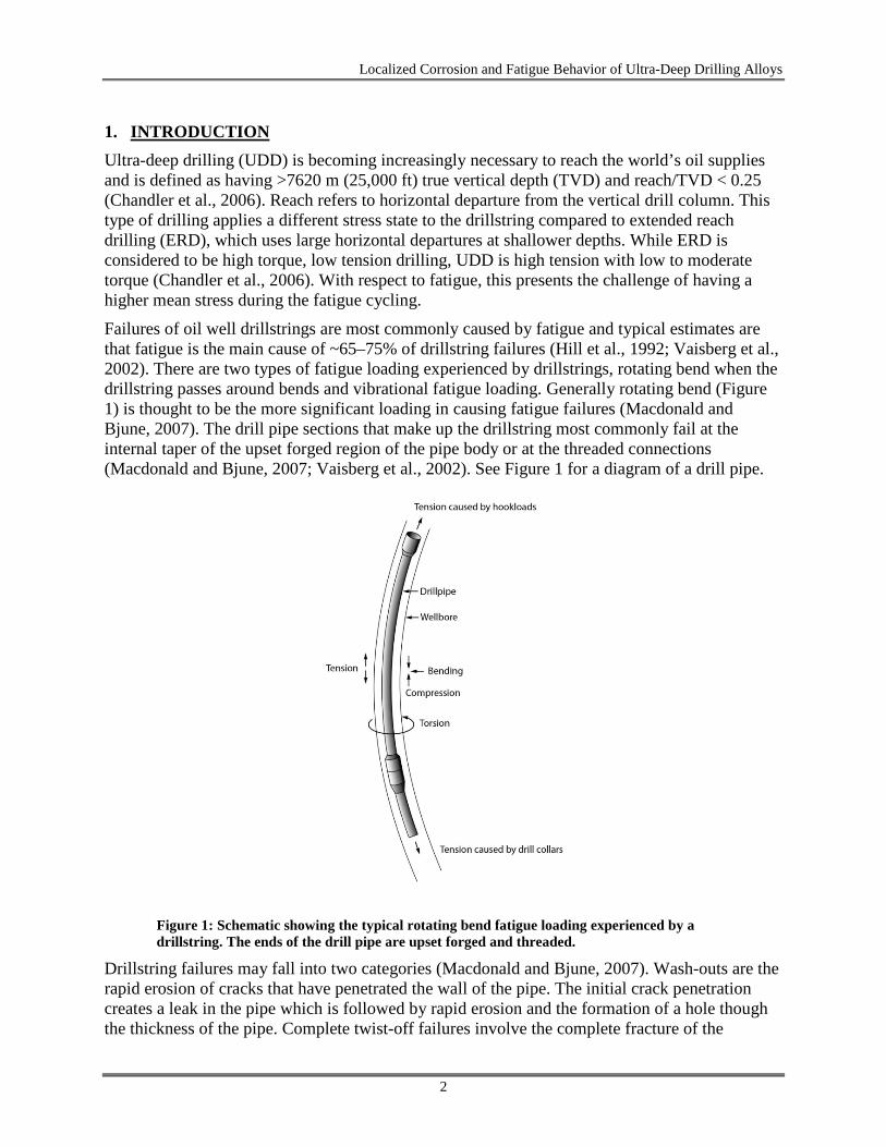
Failures of oil well drillstrings are most commonly caused by fatigue and typical estimates are that fatigue is the main cause of ~65–75% of drillstring failures (Hill et al., 1992; Vaisberg et al., 2002). There are two types of fatigue loading experienced by drillstrings, rotating bend when the drillstring passes around bends and vibrational fatigue loading. Generally rotating bend (Figure 1) is thought to be the more significant loading in causing fatigue failures (Macdonald and Bjune, 2007). The drill pipe sections that make up the drillstring most commonly fail at the internal taper of the upset forged region of the pipe body or at the threaded connections (Macdonald and Bjune, 2007; Vaisberg et al., 2002). See Figure 1 for a diagram of a drill pipe.
Figure 1: Schematic showing the typical rotating bend fatigue loading experienced by a drillstring. The ends of the drill pipe are upset forged and threaded.
Drillstring failures may fall into two categories (Macdonald and Bjune, 2007). Wash-outs are the rapid erosion of cracks that have penetrated the wall of the pipe. The initial crack penetration creates a leak in the pipe which is followed by rapid erosion and the formation of a hole though the thickness of the pipe. Complete twist-off failures involve the complete fracture of the
2
Localized Corrosion and Fatigue Behavior of Ultra-Deep Drilling Alloys
drillstring and the monetary cost of twist-off failures is estimated at roughly ten times that of wash-out failures (Macdonald and Bjune, 2007). The details of the fatigue failures may be further categorized into two types (Hill et al., 1992; Lu et al., 2005; Macdonald and Bjune, 2007; Vaisberg et al., 2002):
1. Fatigue cracking from pre-existing stress concentrations, such as threads or internal tapers (Lu et al., 2005; Macdonald and Bjune, 2007; Vaisberg et al., 2002) or stress concentrations from mechanical damage (Hill et al., 1992; Macdonald and Bjune, 2007; Vaisberg et al., 2002). The propagation of such cracks will generally be accelerated by corrosive environments experienced in drilling, such as H2S from the geologic deposits and chloride ions from drilling fluids (Hill et al., 1992; Vaisberg et al., 2002).
2. Fatigue cracking initiating from corrosion damage, such as pitting (Lu et al., 2005; Macdonald and Bjune, 2007; Vaisberg et al., 2002). Corrosion resistant coatings are often used along the interior of the pipes; however, corrosion pitting and subsequent fatigue failure has often been observed where the coating wears or flakes (Macdonald and Bjune, 2007; Vaisberg et al., 2002). Corrosion inhibiters are often used to help combat corrosion mechanisms.
Drilling to deeper depths causes the drillstring to encounter elevated temperatures (> 392°F (>200°C)) and greater pressures than with more traditional drilling. Additionally, deeper drilling generally requires increasing the strength-to-weight ratio of the drill pipe material while maintaining adequate fracture toughness to prevent catastrophic fatigue failures. This creates a desire for cost-effective, high-strength, high-toughness, low-alloy steels (Chandler et al., 2006; Payne et al., 2003). The American Petroleum Institute (API) standardized steel for high strength is S-135, while higher strength steels such as Z-140, V-150, and UD-165 have been more recently developed to meet the needs of ultra-deep drilling (Brown et al., 2003; Chandler et al., 2006; Payne et al., 2003).
Although drilling muds are fairly non-corrosive to the steels used in drilling, there are several sources of corrosion related phenomena. Often hydrogen sulfide is present in wells, which can lead to corrosion, hydrogen embrittlement, and sulfide stress cracking (Ziomek-Moroz, 2012). Additionally, during the last 15–60 days of drilling, completion fluids are used to prevent damage to rock/clay formations. Depending on the fluid density required and geological formations involved, completion fluids are usually concentrated aqueous solutions containing one or more salts such as CaCl2, NaCl, NH4Cl, KCl, NaBr, CaBr2, or ZnBr2 depending on density, crystallization temperature, and economic requirements (Akers, 2011; Ke and Qu, 2006). Single salt brines generally generate lower corrosion rates than multiple salt brines and corrosivity of the brines generally increases with temperature, brine density, and zinc content (Ke and Qu, 2006). Exposure to such fluids can cause general and localized corrosion of steels, such as pitting, which creates favorable sites for fatigue crack initiation (Akid et al., 2006; Boukerrou and Cottis, 1993; Burns et al., 2012; Horner, et al., 2011; Kawai and Kasai, 1985; Lindley et al., 1982; Wang and Akid, 1996; Yan et al., 1998; Zhou and Turnbull, 1999). Due to the stress concentrating effect of the pits, if corrosion-damaged drill pipes are subsequently reused to drill another well, a drop in fatigue life is expected even if a non-corrosive drilling mud is used.
Accordingly, it is the goal of this report to examine the effect of a typical single-brine completion fluid in causing pitting corrosion for two high-strength drilling alloys, S-135 and
3
Localized Corrosion and Fatigue Behavior of Ultra-Deep Drilling Alloys
UD-165, and the subsequent effect on the fatigue life behavior of those alloys in CaCl2. Literature data indicates that higher corrosion rates were observed for C-90 and 9Cr steels in CaCl2 compared to NaBr at 24°C and 232°C, as well as facilitating higher stress corrosion cracking susceptibility (Craig, 2004). This suggests CaCl2 is fairly aggressive among the single brines. CaCl2 was selected for this study in a high density formulation near the saturation limit. There is also an interest in understanding the corrosion fatigue behavior of these materials while immersed in the corrosive completion fluids, which will be addressed in future studies.
4
Localized Corrosion and Fatigue Behavior of Ultra-Deep Drilling Alloys
2. MATERIALS AND METHODS
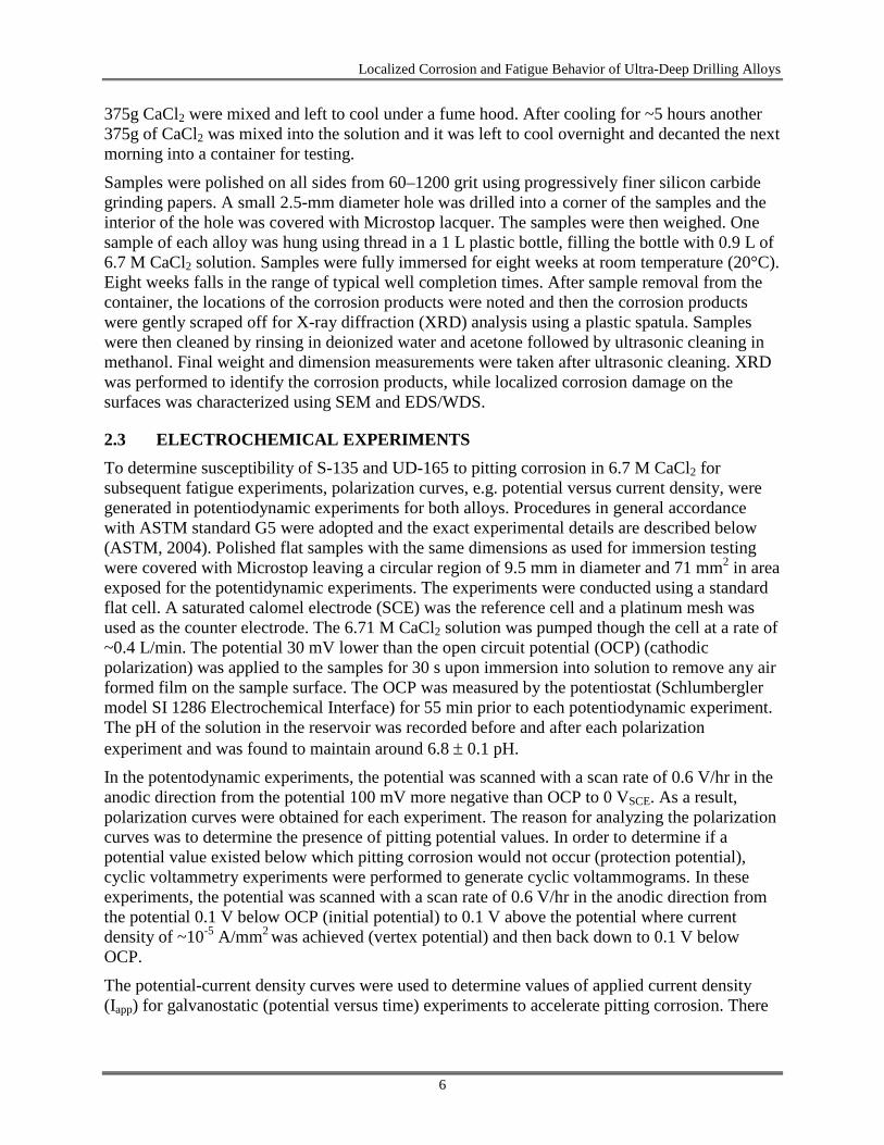
2.1 MATERIALS Roughly 3-m lengths of S-135 and UD-165 drill pipe (NOV Grant Prideco, Navasota, TX) were obtained for this study. The mechanical properties of the alloys are given in Table 1. The tensile properties were provided by the manufacturer (NOV), while the hardness measurements were made by NETL-RUA according to ASTM standard E-18 (ASTM, 2008b). Chemical compositions were determined using combustion-infrared absorbance (S and C), inert gas fusion-thermal conductivity (N), and inductively coupled plasma atomic emission spectroscopy (for all other elements) (ASTM, 2008a). The results of the chemistry determinations for S-135 and UD-165 are found in Table 2. Additionally, samples were machined and polished to a 0.05 µm finish and etched with Nital (2wt.% nitric acid in ethanol) to observe the microstructures. Finally, scanning electron microscopy (SEM) with energy dispersive and wavelength dispersive X-ray spectroscopy (EDS and WDS) were used to identify inclusions found on polished surfaces.
Table 1: Mechanical properties for S-135 and UD-165 pipes used in this study
Property Yield Strength
(MPa) Ultimate Tensile Strength (MPa) Elongation (%) Hardness (HRC)
S-135 1072 1163 19.2 35.1 ± 0.1
UD-165 1211 1258 58.5 40.1 ± 0.2
Table 2: Chemical Compositions for S-135 and UD-165 drill pipe (in wt.%)
Element Al B C Cr Cu Mn Mo N
S-135 0.03 <0.005 0.26 1.39 0.02 0.78 0.68 0.005
UD-165 0.03 <0.005 0.27 0.79 0.19 0.88 0.67 0.007
Element Nb Ni P S Si Sn Ti V
S-135 <0.01 0.02 0.006 0.002 0.3 <0.01 <0.01 <0.01
UD-165 0.02 0.81 <.005 0.007 0.26 <0.01 <0.01 0.07
2.2 IMMERSION TESTING Immersion testing was conducted to ascertain the corrosion mechanism over time scales similar to well completion procedures. Samples measuring 30.5 x 30.5 x 10.2 mm3 and 30.5 x 30.5 x 6.3 mm3 were machined from the thickness of the pipe for S-135 and UD-165, respectively. To prepare the electrolyte, 99.5% purity CaCl2 pellets were mixed with deionized water to a final concentration of 6.71 M (42.9 wt.%). Concentrations in actual completion fluids vary depending on the fluid density needed and rock formations involved (Akers, 2011) and this concentration was chosen as a high-density example near the saturation limit of CaCl2 in water. Because of the exothermic reaction during mixing this was done in two steps. First, 1 L deionized water and
5
Localized Corrosion and Fatigue Behavior of Ultra-Deep Drilling Alloys
375g CaCl2 were mixed and left to cool under a fume hood. After cooling for ~5 hours another 375g of CaCl2 was mixed into the solution and it was left to cool overnight and decanted the next morning into a container for testing.
Samples were polished on all sides from 60–1200 grit using progressively finer silicon carbide grinding papers. A small 2.5-mm diameter hole was drilled into a corner of the samples and the interior of the hole was covered with Microstop lacquer. The samples were then weighed. One sample of each alloy was hung using thread in a 1 L plastic bottle, filling the bottle with 0.9 L of 6.7 M CaCl2 solution. Samples were fully immersed for eight weeks at room temperature (20°C). Eight weeks falls in the range of typical well completion times. After sample removal from the container, the locations of the corrosion products were noted and then the corrosion products were gently scraped off for X-ray diffraction (XRD) analysis using a plastic spatula. Samples were then cleaned by rinsing in deionized water and acetone followed by ultrasonic cleaning in methanol. Final weight and dimension measurements were taken after ultrasonic cleaning. XRD was performed to identify the corrosion products, while localized corrosion damage on the surfaces was characterized using SEM and EDS/WDS.
2.3 ELECTROCHEMICAL EXPERIMENTS To determine susceptibility of S-135 and UD-165 to pitting corrosion in 6.7 M CaCl2 for subsequent fatigue experiments, polarization curves, e.g. potential versus current density, were generated in potentiodynamic experiments for both alloys. Procedures in general accordance with ASTM standard G5 were adopted and the exact experimental details are described below (ASTM, 2004). Polished flat samples with the same dimensions as used for immersion testing were covered with Microstop leaving a circular region of 9.5 mm in diameter and 71 mm2 in area exposed for the potentidynamic experiments. The experiments were conducted using a standard flat cell. A saturated calomel electrode (SCE) was the reference cell and a platinum mesh was used as the counter electrode. The 6.71 M CaCl2 solution was pumped though the cell at a rate of ~0.4 L/min. The potential 30 mV lower than the open circuit potential (OCP) (cathodic polarization) was applied to the samples for 30 s upon immersion into solution to remove any air formed film on the sample surface. The OCP was measured by the potentiostat (Schlumbergler model SI 1286 Electrochemical Interface) for 55 min prior to each potentiodynamic experiment. The pH of the solution in the reservoir was recorded before and after each polarization experiment and was found to maintain around 6.8 ± 0.1 pH. In the potentodynamic experiments, the potential was scanned with a scan rate of 0.6 V/hr in the anodic direction from the potential 100 mV more negative than OCP to 0 VSCE. As a result, polarization curves were obtained for each experiment. The reason for analyzing the polarization curves was to determine the presence of pitting potential values. In order to determine if a potential value existed below which pitting corrosion would not occur (protection potential), cyclic voltammetry experiments were performed to generate cyclic voltammograms. In these experiments, the potential was scanned with a scan rate of 0.6 V/hr in the anodic direction from the potential 0.1 V below OCP (initial potential) to 0.1 V above the potential where current density of ~10-5 A/mm2 was achieved (vertex potential) and then back down to 0.1 V below OCP. The potential-current density curves were used to determine values of applied current density (Iapp) for galvanostatic (potential versus time) experiments to accelerate pitting corrosion. There
6
Localized Corrosion and Fatigue Behavior of Ultra-Deep Drilling Alloys
were a minimum of two polarization curves generated for each experimental condition, each using a fresh sample.
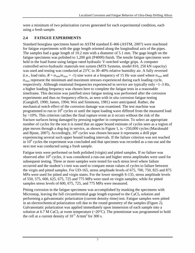
2.4 FATIGUE EXPERIMENTS Standard hourglass specimens based on ASTM standard E-466 (ASTM, 2007) were machined for fatigue experiments with the gage length oriented along the longitudinal axis of the pipes. The samples had a gage length of 10.2 mm with a diameter of 5.1 mm. The gage length on the fatigue specimens was polished to 1,200 grit (P4000) finish. The tensile fatigue specimens were held in the load frame using fatigue rated hydraulic V-notched wedge grips. A computer controlled servo-hydraulic materials test system (MTS Systems, model 810, 250 kN capacity) was used and testing was conducted at 23°C in 30–40% relative humidity air. A fully reversed (i.e., load ratio, R = σmin/σmax = -1) sine wave at a frequency of 15 Hz was used where σmin and σmax represent the minimum and maximum stresses experienced during each loading cycle, respectively. Although rotational frequencies experienced in service are typically only ~1–3 Hz, a higher loading frequency was chosen here to complete the fatigue tests in a reasonable timeframe. This decision was justified since fatigue testing was performed after the corrosion experiments and thus no frequency effects, as seen with in situ corrosion fatigue testing (Gangloff, 1990; James, 1994; Wei and Simmons, 1981) were anticipated. Rather, the mechanical notch effect of the corrosion damage was examined. The test machine was programmed to run to 106 cycles or until the input loading wave differed from the measured load by >10%. This criterion catches the final rupture event as it occurs without the risk of the fracture surfaces being damaged by pressing together in compression. To select an appropriate number of cycles for the test it is noted that an upper bound estimate of cycles seen as a region of pipe moves through a dog-leg in service, as shown in Figure 1, is ~250,000 cycles (Macdonald and Bjune, 2007). Accordingly, 106 cycles was chosen because it represents a drill pipe experiencing several such upper bound loading intervals. If the failure criterion was not reached in 106 cycles the experiment was concluded and that specimen was recorded as a run-out and the next test was conducted using a fresh sample.
Fatigue tests were performed on both polished (virgin) and pitted samples. If no failure was observed after 106 cycles, it was considered a run-out and higher stress amplitudes were used for subsequent testing. Three or more samples were tested for each stress level where failure occurred and the student’s t-test was used to compare mean values of cycles to failure between the virgin and pitted samples. For UD-165, stress amplitude levels of 675, 700, 750, 825 and 875 MPa were used for pitted and virgin states. For the lower strength S-135, stress amplitude levels of 550, 575, 600, 625, 675, 725 and 775 MPa were used on virgin samples; while for pitted samples stress levels of 600, 675, 725, and 775 MPa were measured.
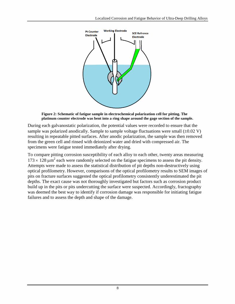
Pitting corrosion in the fatigue specimens was accomplished by masking the specimens with Microstop, leaving the full circumferential gage length exposed to the CaCl2 solution and performing a galvanostatic polarization (current density–time) test. Fatigue samples were pitted in an electrochemical polarization cell due to the round geometry of the samples (Figure 2). Galvanostatic polarization was applied immediately upon immersion of each sample into a solution at 6.7 M CaCl2 at room temperature (~20°C). The potentiostat was programmed to hold the cell at a current density of 10-5 A/mm2 for 300 s.
7
Localized Corrosion and Fatigue Behavior of Ultra-Deep Drilling Alloys
Figure 2: Schematic of fatigue sample in electrochemical polarization cell for pitting. The platinum counter electrode was bent into a ring shape around the gage section of the sample.
During each galvanostatic polarization, the potential values were recorded to ensure that the sample was polarized anodically. Sample to sample voltage fluctuations were small (±0.02 V) resulting in repeatable pitted surfaces. After anodic polarization, the sample was then removed from the green cell and rinsed with deionized water and dried with compressed air. The specimens were fatigue tested immediately after drying.
To compare pitting corrosion susceptibility of each alloy to each other, twenty areas measuring 173 × 128 µm2 each were randomly selected on the fatigue specimens to assess the pit density. Attempts were made to assess the statistical distribution of pit depths non-destructively using optical profilometry. However, comparisons of the optical profilometry results to SEM images of pits on fracture surfaces suggested the optical profilometry consistently underestimated the pit depths. The exact cause was not thoroughly investigated but factors such as corrosion product build up in the pits or pits undercutting the surface were suspected. Accordingly, fractography was deemed the best way to identify if corrosion damage was responsible for initiating fatigue failures and to assess the depth and shape of the damage.
8
Localized Corrosion and Fatigue Behavior of Ultra-Deep Drilling Alloys
3. RESULTS
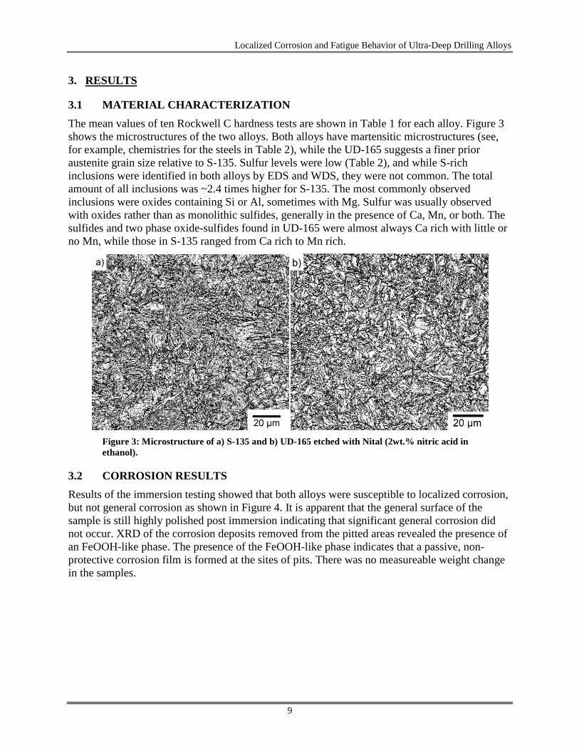
3.1 MATERIAL CHARACTERIZATION The mean values of ten Rockwell C hardness tests are shown in Table 1 for each alloy. Figure 3 shows the microstructures of the two alloys. Both alloys have martensitic microstructures (see, for example, chemistries for the steels in Table 2), while the UD-165 suggests a finer prior austenite grain size relative to S-135. Sulfur levels were low (Table 2), and while S-rich inclusions were identified in both alloys by EDS and WDS, they were not common. The total amount of all inclusions was ~2.4 times higher for S-135. The most commonly observed inclusions were oxides containing Si or Al, sometimes with Mg. Sulfur was usually observed with oxides rather than as monolithic sulfides, generally in the presence of Ca, Mn, or both. The sulfides and two phase oxide-sulfides found in UD-165 were almost always Ca rich with little or no Mn, while those in S-135 ranged from Ca rich to Mn rich.
Figure 3: Microstructure of a) S-135 and b) UD-165 etched with Nital (2wt.% nitric acid in ethanol).
3.2 CORROSION RESULTS Results of the immersion testing showed that both alloys were susceptible to localized corrosion, but not general corrosion as shown in Figure 4. It is apparent that the general surface of the sample is still highly polished post immersion indicating that significant general corrosion did not occur. XRD of the corrosion deposits removed from the pitted areas revealed the presence of an FeOOH-like phase. The presence of the FeOOH-like phase indicates that a passive, non-protective corrosion film is formed at the sites of pits. There was no measureable weight change in the samples.
9
Localized Corrosion and Fatigue Behavior of Ultra-Deep Drilling Alloys
Figure 4: Representative picture showing a corrosion pit after immersion testing of S-135. Note the polishing marks around the pit indicating a lack of general corrosion.
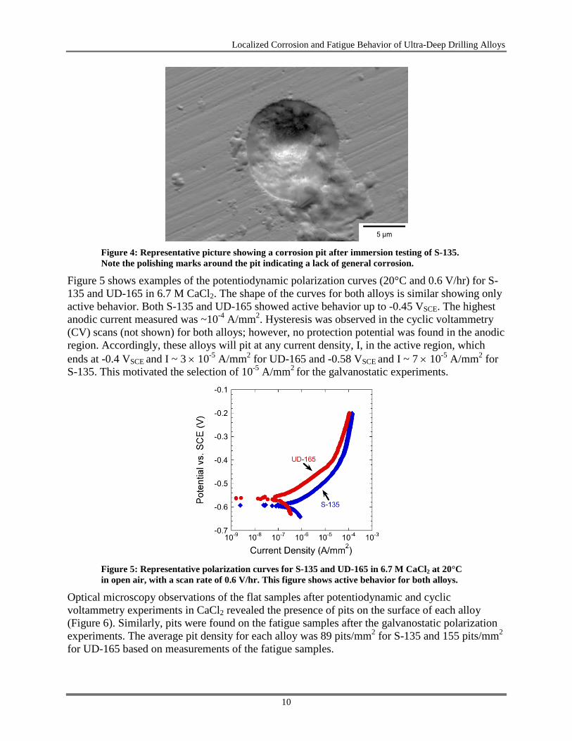
Figure 5 shows examples of the potentiodynamic polarization curves (20°C and 0.6 V/hr) for S-135 and UD-165 in 6.7 M CaCl2. The shape of the curves for both alloys is similar showing only active behavior. Both S-135 and UD-165 showed active behavior up to -0.45 VSCE. The highest anodic current measured was ~10-4 A/mm2. Hysteresis was observed in the cyclic voltammetry (CV) scans (not shown) for both alloys; however, no protection potential was found in the anodic region. Accordingly, these alloys will pit at any current density, I, in the active region, which ends at -0.4 VSCE and I ~ 3 × 10⁻⁵ A/mm2 for UD-165 and -0.58 VSCE and I ~ 7 × 10⁻⁵ A/mm2 for S-135. This motivated the selection of 10-5 A/mm2 for the galvanostatic experiments.
Figure 5: Representative polarization curves for S-135 and UD-165 in 6.7 M CaCl2 at 20°C in open air, with a scan rate of 0.6 V/hr. This figure shows active behavior for both alloys.
Optical microscopy observations of the flat samples after potentiodynamic and cyclic voltammetry experiments in CaCl2 revealed the presence of pits on the surface of each alloy (Figure 6). Similarly, pits were found on the fatigue samples after the galvanostatic polarization experiments. The average pit density for each alloy was 89 pits/mm2 for S-135 and 155 pits/mm2 for UD-165 based on measurements of the fatigue samples.
10
Localized Corrosion and Fatigue Behavior of Ultra-Deep Drilling Alloys
Figure 6: Representative optical micrograph of the surface of an S-135 sample after a potentiodynamic scan at 0.6 V/hr showing corrosion pits present.
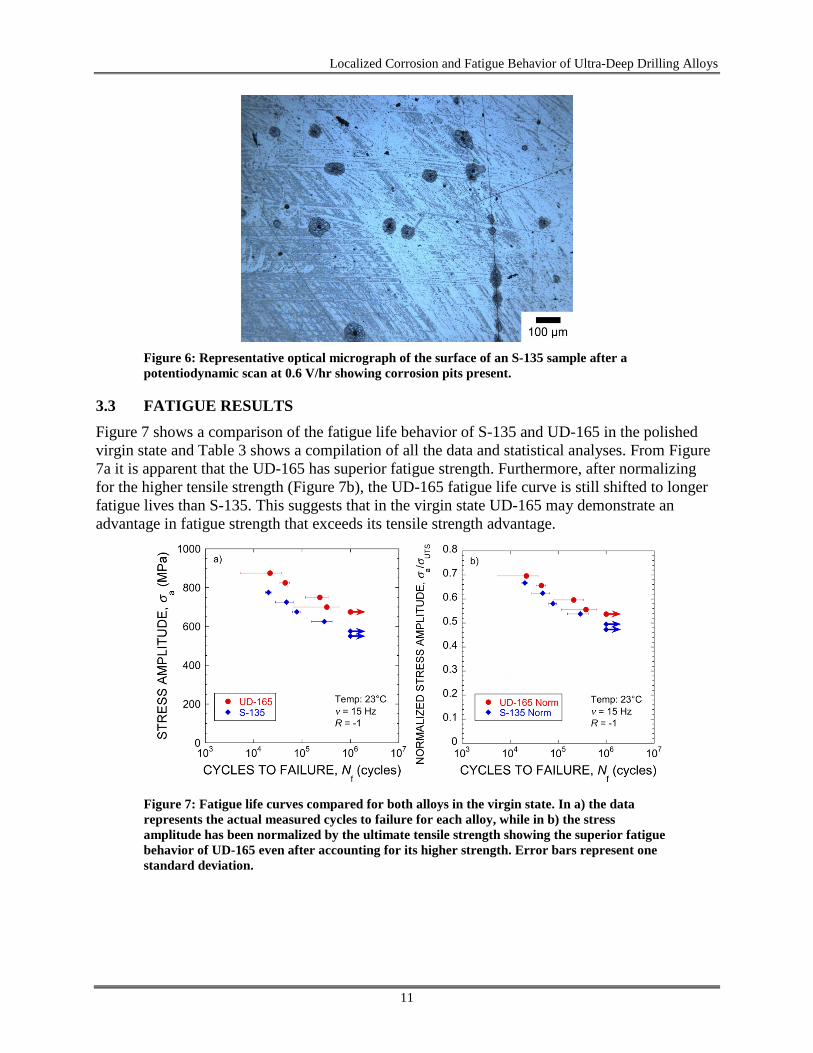
3.3 FATIGUE RESULTS Figure 7 shows a comparison of the fatigue life behavior of S-135 and UD-165 in the polished virgin state and Table 3 shows a compilation of all the data and statistical analyses. From Figure 7a it is apparent that the UD-165 has superior fatigue strength. Furthermore, after normalizing for the higher tensile strength (Figure 7b), the UD-165 fatigue life curve is still shifted to longer fatigue lives than S-135. This suggests that in the virgin state UD-165 may demonstrate an advantage in fatigue strength that exceeds its tensile strength advantage.
Figure 7: Fatigue life curves compared for both alloys in the virgin state. In a) the data represents the actual measured cycles to failure for each alloy, while in b) the stress amplitude has been normalized by the ultimate tensile strength showing the superior fatigue behavior of UD-165 even after accounting for its higher strength. Error bars represent one standard deviation.
11
Localized Corrosion and Fatigue Behavior of Ultra-Deep Drilling Alloys
Table 3: Compiled fatigue data and statistical analysis results
Alloy Stress [MPa]
Average Cycles to Failure (Virgin
Samples)
Standard Deviation
(Virgin Samples)
Number of Samples Tested (Virgin
Samples)
Average Cycles to Failure (Pitted
Samples)
Standard Deviation
(Pitted Samples)
Number of Samples Tested (Pitted
Samples)
P-Value
S-135 600 261,143 133,923 3 399,261 480,241 3 0.656
S-135 625 289,688 133,049 3 n/a n/a 0 n/a
S-135 675 78,106 15,032 3 53,617 22,822 3 0.196
S-135 725 47,662 19,480 3 31,326 6,712 3 0.242
S-135 775 20,269 2,818 3 16,621 1,646 3 0.125
UD-165 675 1,000,000 0 2 414,893 513,571 3 0.224
UD-165 700 377,826 261,580 3 43,507 9,249 3 0.068
UD-165 750 209,995 128,787 3 28,450 8,642 3 0.016
UD-165 825 44,725 10,176 3 16,672 3,522 3 0.011
UD-165 875 21,751 16,448 3 13,297 2,561 3 0.429
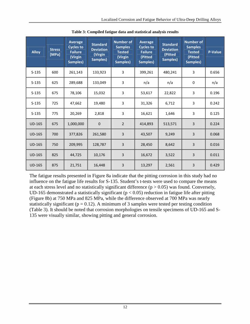
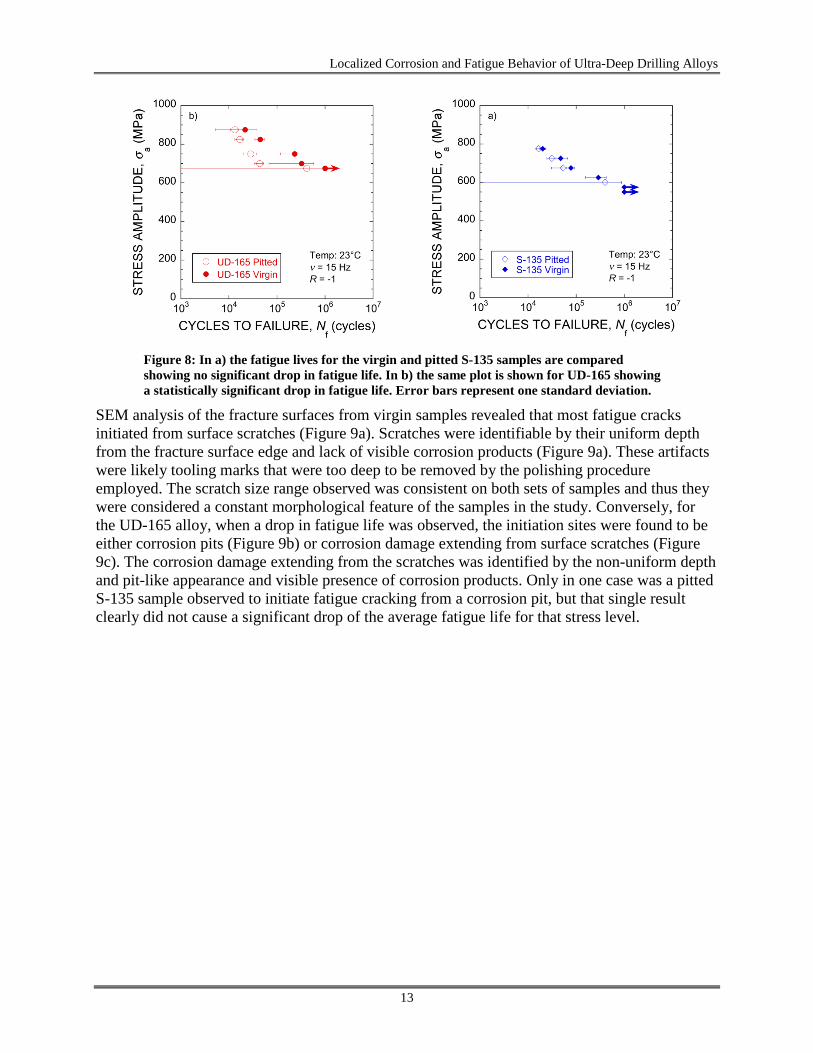
The fatigue results presented in Figure 8a indicate that the pitting corrosion in this study had no influence on the fatigue life results for S-135. Student’s t-tests were used to compare the means at each stress level and no statistically significant difference (p > 0.05) was found. Conversely, UD-165 demonstrated a statistically significant (p < 0.05) reduction in fatigue life after pitting (Figure 8b) at 750 MPa and 825 MPa, while the difference observed at 700 MPa was nearly statistically significant (p = 0.12). A minimum of 3 samples were tested per testing condition (Table 3). It should be noted that corrosion morphologies on tensile specimens of UD-165 and S-135 were visually similar, showing pitting and general corrosion.
12
Localized Corrosion and Fatigue Behavior of Ultra-Deep Drilling Alloys
Figure 8: In a) the fatigue lives for the virgin and pitted S-135 samples are compared showing no significant drop in fatigue life. In b) the same plot is shown for UD-165 showing a statistically significant drop in fatigue life. Error bars represent one standard deviation.
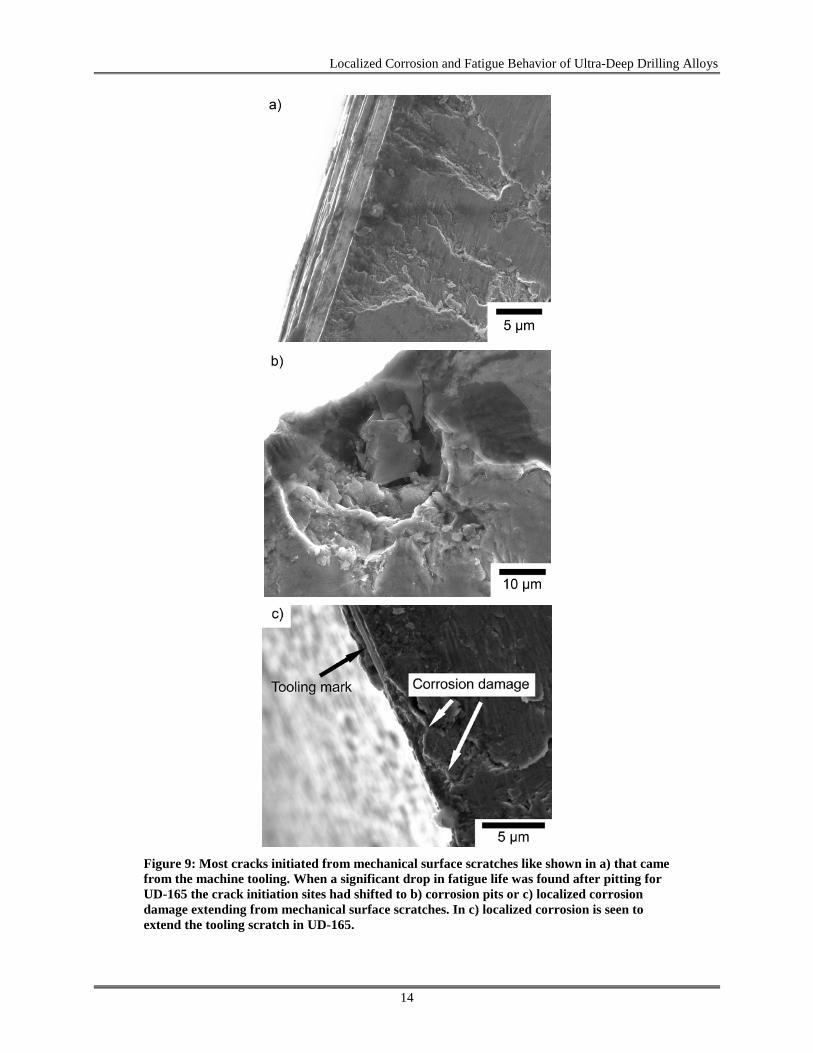
SEM analysis of the fracture surfaces from virgin samples revealed that most fatigue cracks initiated from surface scratches (Figure 9a). Scratches were identifiable by their uniform depth from the fracture surface edge and lack of visible corrosion products (Figure 9a). These artifacts were likely tooling marks that were too deep to be removed by the polishing procedure employed. The scratch size range observed was consistent on both sets of samples and thus they were considered a constant morphological feature of the samples in the study. Conversely, for the UD-165 alloy, when a drop in fatigue life was observed, the initiation sites were found to be either corrosion pits (Figure 9b) or corrosion damage extending from surface scratches (Figure 9c). The corrosion damage extending from the scratches was identified by the non-uniform depth and pit-like appearance and visible presence of corrosion products. Only in one case was a pitted S-135 sample observed to initiate fatigue cracking from a corrosion pit, but that single result clearly did not cause a significant drop of the average fatigue life for that stress level.
13
Localized Corrosion and Fatigue Behavior of Ultra-Deep Drilling Alloys
Figure 9: Most cracks initiated from mechanical surface scratches like shown in a) that came from the machine tooling. When a significant drop in fatigue life was found after pitting for UD-165 the crack initiation sites had shifted to b) corrosion pits or c) localized corrosion damage extending from mechanical surface scratches. In c) localized corrosion is seen to extend the tooling scratch in UD-165.
14
Localized Corrosion and Fatigue Behavior of Ultra-Deep Drilling Alloys
4. DISCUSSION The samples immersed in 6.7 M CaCl2 at 20°C underwent pitting corrosion with the formation of a non-protective film FeOOH over the pitted sites. The pitting mechanism is well known and details may be found in the published literature (Wranglen, 1974). Of importance to this study is the role of sulfide inclusions as initiation sites for localized corrosion (Akid et al., 2006; Wang and Akid, 1996; Yan et al., 1998; James, 1994; Suresh, 1998; Eklund, 1971) and the result that the UD-165 alloy was found to have a larger sulfur concentration compared to S-135 by almost 3.5 times (Table 2). Since monolithic sulfide inclusions were not in sufficient concentration to explain the measured concentration of pits, it is concluded that the pits nucleated primarily at sulfide enveloped oxide inclusions as has been reported in other studies on low alloy carbon steels (Eklund, 1971; Reformatskaya and Freiman, 2001). Those previous studies have shown that not all sulfide enveloped oxides are active pit initiators and a critical amount of sulfur is needed to be active (Eklund, 1971). Thus, the higher sulfur content of the UD-165 alloy, coupled with the lower total number of oxide inclusions at which to distribute the sulfur, facilitated a higher number of active pit initiators and the larger number of observed pits. Further contributing to this issue is the fact that calcium sulfides were predominantly found in UD-165 and they are known to be more active than manganese sulfides in causing local corrosion in steels (Reformatskaya and Freiman, 2001).
It is apparent that pitting corrosion by anodic polarization dropped the fatigue life for UD-165 at stress amplitudes of 750 MPa and 825 MPa. For stress amplitude of 700 MPa statistical confidence that the pitted and virgin means were different was not found (p = 0.12). While p = 0.12 is not generally considered statistically significant, there is much scatter in the virgin data for 700 MPa and it is expected that the confidence would increase with a larger sample size. Larger scatter in fatigue life is common at lower stress values for unnotched samples where larger fraction of the life is governed by the stochastic process of initiating a dominant crack (Suresh, 1998). Conversely, no effect of pitting was observed for UD-165 at the highest stress amplitude (p > 0.05). This is attributed to crack initiation occurring very quickly at high stresses, making the total life relatively less sensitive to variations in surface roughness, i.e., scratches and/or pits (Arola and Williams, 2002; Suresh, 1998; Taylor and Clancy, 1991).
The accelerated pitting corrosion in the pre-exposed fatigue specimens made the fatigue lives of UD-165 and S-135 overlap over the intermediate stress ranges tested (Figure 10). This suggests that after equal localized corrosion exposure in simulated drilling completion fluid (6.7 M CaCl2) the fatigue strength advantage of UD-165 over S-135 was greatly reduced at high stress levels. This is attributed to the higher sulfur concentration (Table 2) leading to more sulfide concentrated at oxide inclusions, a larger number of pits during accelerated corrosion experiments, and visible localized corrosion damage (pits, crevice corrosion) at the fatigue crack initiation sites (Figures 9b and 9c).
15
Localized Corrosion and Fatigue Behavior of Ultra-Deep Drilling Alloys
Figure 10: Comparison of the pitted fatigue lives of S-135 and UD-165 showing considerable overlap of the curves at the intermediate stress levels tested.
Pitting corrosion is a well-known phenomenon that leads to fatigue crack initiation and subsequent fatigue failures in drill pipes (Lu et al., 2005; Macdonald and Bjune, 2007; Vaisberg et al., 2002). A high sulfur concentration has also been shown to promote pit initiation mechanisms for low alloy steels (Akid et al, 2006; Wang and Akid, 1996; Yan et al, 1998; James, 1994; Suresh, 1998). This will likely be an issue in a variety of completion fluids beyond the single CaCl2 brine examined here and it is expected the UD-165 drilling pipe with lower sulfur content than observed in this study will be desirable in order to maintain the superior fatigue failure resistance compared to more traditional pipe alloys like S-135.
In another study of high-strength, steel-riser steels (Hudak et al., 2011), in-situ axial tension fatigue tests were conducted in simulated sea water (i.e., near the surface in the splash zone) as well as sour brine (i.e., deep well environment where H2S is present). The results of the in situ tests were compared to identical tensile fatigue tests conducted under ambient conditions to evaluate the effect of the environment on fatigue life. These results showed a decrease in the ambient fatigue life for both environments, with the sour brine environment exhibiting the largest decrement. One significant aspect of that research was the reduction in fatigue life for under-simulated sea water and sour brine conditions. This is very much similar to the change noted between the pitted S-135 and UD-165 specimens (exposed to single brine completion fluid) and the non-exposed ones. Testing was conducted differently. One set used pre-exposed samples with corrosion pits. The second series of tests were conducted in situ.
Also, another interesting trend was observed in both research results. The effect of yield strength on improving overall fatigue life in the riser steels was not significant. Specifically, in terms of the overall life there was no significant separation in fatigue life at high stress levels. The higher strength riser steels had, in general, longer fatigue lives at these higher stress level but the data from all tests (i.e., five riser steels at five different yield stress levels) was not significantly different. It fell within the expected scatter from high-cycle fatigue tests. However, close inspection of the data showed slightly different fatigue endurance limits at 10 million cycles for each of the riser steels. The higher strength steels had increasingly higher endurance limits compared to the lower strength steels. This same trend was also observed for S-135 and UD-165.
16
Localized Corrosion and Fatigue Behavior of Ultra-Deep Drilling Alloys
The UD-165 had a higher endurance limit compared to the S-135. Therefore, while much of the difference in fatigue life at higher stress levels disappears due to the damage from exposure to the single brine completion fluid (i.e., pit generation), the difference in fatigue limit between S-135 and UD-165 remained.
From a metallurgical standpoint the sulfur in UD-165 is problematical. While it cannot be directly proven at this time, the results of fatigue tests for samples exposed to the completion brine suggest that sulfur leads to increased pitting. Thus, more sites for fatigue crack initiation and propagation are present in UD-165. This manifests as a greater reduction in fatigue life for the pre-exposed UD-165 fatigue specimens. The same trend occurred for S-135, but to a lesser extent. It is tempting to try to relate pit areal density to fatigue life; however, at this juncture insufficient tests have been conducted to unambiguously make this correlation. What might be suggested is to produce UD-165 with less sulfur and then expose coupons to the single brine completion fluid. If the number of pits on the surface decreases then there might also be a corresponding change in the extent of fatigue life decrement.
17
Localized Corrosion and Fatigue Behavior of Ultra-Deep Drilling Alloys
5. CONCLUSIONS Based on this study of the corrosion and fatigue behavior of two ultra-deep oil drilling alloys, S-135 and UD-165, the following conclusions can be made:
• Both S-135 and UD-165 alloys were susceptible to pitting corrosion, upon immersion in a 6.7 M CaCl2 simulated drilling completion fluid.
• UD-165 has superior fatigue strength relative to S-135 for polished (virgin) specimens during fully reversed fatigue life testing, which simulates the rotating bend fatigue loading found in oil drilling. Even after normalizing for the tensile strength the UD-165 fatigue life curve was still found to be shifted to longer fatigue lives than S-135.
• The endurance limit of UD-165 (∼675 MPa) was also higher than the endurance limit for S-135 (∼600 MPa). The endurance limit for each steel did not change as a result of exposure to the single brine completion fluid.
• UD-165 was found to have a higher areal density of pits on the sample surface relative to S-135 (i.e., 155 pits/mm2 compared to 89 pits/mm2) after galvanostatic experiments were used to accelerate pitting corrosion. This was attributed to higher sulfur content in UD-165, which led to a higher number of active initiation sites.
• Subsequent fatigue life experiments demonstrated that pitting due to exposure in the single brine completion fluid reduced the fatigue strength advantage of UD-165 at higher stress levels, and both steels showed comparable fatigue behavior at these stress levels.
• The decrease in fatigue strength for UD-165 at the higher stress levels was traced to crack initiation at either (i) corrosion pits or (ii) relatively deep surface scratches.
18
Localized Corrosion and Fatigue Behavior of Ultra-Deep Drilling Alloys
6. REFERENCES Akers, T. J. Salinity-Based Pump-and-Dump Strategy for Drilling Salt With Supersaturated
Fluids. SPE Drilling & Completion 2011, 26, 151–159.
Akid, R.; Drnytrakh, I. M.; Gonzalez-Sanchez, J. Fatigue damage accumulation: The role of corrosion on the early stages of crack development. Corros. Eng. Sci. Technol. 2006, 41 328–335.
Arola, D.; Williams, C. L. Estimating the fatigue stress concentration factor of machined surfaces. Int. J. Fatigue 2002, 24, 923–930.
ASTM Standard E1019. Standard Test Methods for Determination of Carbon, Sulfur, Nitrogen, and Oxygen in Steel, Iron, Nickel, and Cobalt Alloys by Various Combustion and Fusion Techniques. ASTM International: West Conshohocken, PA, 2008a. DOI: 10.1520/E1019-08. http://www.astm.org
ASTM Standard E18. Standard Test Methods for Rockwell Hardness of Metallic Materials; ASTM International: West Conshohocken, PA, 2008b. DOI: 10.1520/E0018-08B. http://www.astm.org
ASTM Standard E466. Standard Practice for Conducting Force Controlled Constant Amplitude Axial Fatigue Tests of Metallic Materials; ASTM International: West Conshohocken, PA, 2007. DOI: 10.1520/E0466-07. http://www.astm.org
ASTM Standard G5. Standard Reference Test Method for Making Potentiostatic and Potentiodynamic Anodic Polarization Measurements; ASTM International: West Conshohocken, PA, 2004. DOI: 10.1520/G0005-94R04. http://www.astm.org
Boukerrou, A.; Cottis, R. A. Crack Initiation in the Corrosion-Fatigue of Structural-Steels in Salt-Solutions. Corrosion Sci. 1993, 35, 577–585.
Brown, G.; Belczewski, D.; Mostoway, J.; Jellison, M. J. Game changing drilling tubular technologies. In CADE/CAODC Drilling Conference, Calgery, Alberta, Canada, 2003.
Burns, J. T.; Larsen, J. M.; Ganglof, R. P. Effect of initiation feature on microstructure-scale fatigue crack propagation in Al–Zn–Mg–Cu. International Journal of Fatigue 2012, 42,104–121. http://dx.doi.org/10.1016/j.ijfatigue.2011.08.001.
Chandler, R. B.; Jellison, M. J.; Payne, M. L.; Shepard, J. S. Advanced and emerging drillstring technologies overcome operational challenges. World Oil 2006, 23–34.
Craig, B. D. Oilfield Metallurgy and Corrosion. 3rd ed.; NACE International, 2004; p 282.
Eklund, G. The relation between slag inclusions and corrosion. In Proceedings of the U. R. Evans Conference on Localized Corrosion, Williamsburg, VA; Brown, B. F., Kruger, J., Staehle, R. W., Eds.; National Association of Corrosion Engineers: Houston, TX, 1971; pp 477–481.
Gangloff, R. P. Corrosion fatigue crack propagation in metals. In 1st International Conference on Environment-Induced Cracking of Metals, Kohler, WI; Gangloff, R. P., Ives, M. B., Eds.; National Association of Corrosion Engineers: Houston, TX, 1990; pp 55–109.
19
Localized Corrosion and Fatigue Behavior of Ultra-Deep Drilling Alloys
Hill, T. H.; Seshadri, P. V.; Durhan, K. S. A Unified Approach to Drillstem-Failure Prevention. SPE Drilling Engineering 1992, 7, 254–260.
Horner, D. A.; Connolly, B. J.; Zhou, S.; Crocker, L.; Turnbull, A. Novel images of the evolution of stress corrosion cracks from corrosion pits. Corrosion Sci. 2011, 53 (11), 3466-3485.
Hudak, Jr., S. J.; Robledo, G. B.; Hawk, J. A. Corrosion-Fatigue Performance of High-Strength Riser Steels In Seawater and Sour Brine Environments. Proceedings of the 30th International Conference on Ocean, Offshore and Arctic Engineering (OMAE 2011), Volume 3: Materials Technology, ASME, 2011; pp. 531–539, Paper No. OMAE2011-50171.
James, L. A. The Effect of Temperature and Cyclic Frequency Upon Fatigue-Crack Growth-Behavior of Several Steels in an Elevated-Temperature Aqueous Environment. J. Press. Vessel Technol.-Trans. ASME 1994, 116, 122–127.
Kawai, S.; Kasai, K. Considerations of Allowable Stress of Corrosion Fatigue (Focused on the Influence of Pitting). Fatigue Fract. Eng. Mater. Struct. 1985, 8, 115–127.
Ke, M.; Qu, Q. Thermal Decomposition of Thiocynate Corrosion Inhibitors: A Potential for Successful Well Completions. In International Symposium and Exhibition on Formation Damage Control, 15-17 February 2006, Society of Petroleum Engineers, Lafayette, LA, 2006; pp 98302-MS.
Lindley, T. C.; McIntyre, P.; Trant, P. J. Fatigue-Crack Initiation at Corrosion Pits. Metals Technology 1982, 9, 135–142.
Lu, S. L.; Feng, Y. R.; Luo, F. Q.; Qin, C. Y.; Wang, X. H. Failure analysis of IEU drill pipe wash out. International Journal of Fatigue 2005, 27, 1360–1365.
Macdonald, K. A.; Bjune, J. V. Failure analysis of drillstrings. Engineering Failure Analysis 2007, 14, 1641–1666.
Payne, M. L.; Chandler, B.; Jellison, M. J.; Shepard, J. Recent key advances in drillstring technology. World Oil 2003, 224, 53–58.
Reformatskaya, I. I.; Freiman, L. I. Precipitation of sulfide inclusions in steel structure and their effect on local corrosion processes. Protection of Metals 2001, 37, 459–464.
Suresh, S. Fatigue of Materials, 2nd Ed.; Cambridge University Press: Cambridge, 1998; p 679.
Taylor, D.; Clancy, O. M. The Fatigue Performance of Machined Surfaces. Fatigue Fract. Eng. Mater. Struct. 1991, 14, 329–336.
Vaisberg, O.; Vincke, O.; Perrin, G.; Sarda, J. P.; Fay, J. B. Fatigue of drillstring: State of the art. Oil & Gas Science and Technology-Revue De L Institut Francais Du Petrole 2002, 57, 7–37.
Wang, Y.; Akid, R. Role of nonmetallic inclusions in fatigue, pitting, and corrosion fatigue. Corrosion 1996, 52, 92–102.
Wei, R. P.; Simmons, G. W. Recent Progress in Understanding Environment Assisted Fatigue Crack-Growth. Int. J. Fract. 1981, 17, 235–247.
Wranglen, G., Pitting and Sulfide Inclusions in Steel. Corrosion Sci. 1974, 14, 331–349.
20
Localized Corrosion and Fatigue Behavior of Ultra-Deep Drilling Alloys
Yan, L.; Inagaki, S.; Kodama, H.; Kimura, K. The initiation of corrosion fatigue cracking from pitting in 3.5Ni-Cr-Mo-V low-pressure rotor steel. JSME Int. J. Ser. B-Fluids Therm. Eng. 1998, 41, 740–745.
Zhou, S.; Turnbull, A. Influence of pitting on the fatigue life of a turbine blade steel. Fatigue Fract. Eng. Mater. Struct. 1999, 22, 1083–1093.
Ziomek-Moroz, M. Environmetally assited cracking of drill pipes in deep drilling oil and natural gas wells. Journal of Materials Engineering and Performance 2012, 21, 1061–1069
21

Localized Corrosion and Fatigue Behavior of Ultra-Deep Drilling Alloys
This page intentionally left blank.
22
The National Energy Technology Laboratory (NETL) conducts cutting-edge energy research and technology development and analyzes energy systems and international energy issues for the U.S. Department of Energy. The NETL-Regional University Alliance (NETL-RUA) is an applied research collaboration that combines NETL’s energy research expertise with the broad capabilities of five nationally recognized, regional universities: Carnegie Mellon University (CMU), The Pennsylvania State University (PSU), University of Pittsburgh (Pitt), Virginia Polytechnic Institute and State University (VT), and West Virginia University (WVU), and the engineering and construction expertise of an industry partner (URS). The NETL-RUA leverages its expertise with current fossil energy sources to discover and develop sustainable energy systems of the future, introduce new technology, and boost economic development and national security.
Brad Tomer, Acting Director Strategic Center for Natural Gas and Oil National Energy Technology Laboratory U.S. Department of Energy Maria Vargas Deputy Director Strategic Center for Natural Gas and Oil National Energy Technology Laboratory U.S. Department of Energy Roy Long Technology Manager Strategic Center for Natural Gas and Oil National Energy Technology Laboratory U.S. Department of Energy Elena Melchert Program Manager Oil & Gas Production Office of Fossil Energy U.S. Department of Energy
Cynthia Powell Director Office of Research and Development National Energy Technology Laboratory U.S. Department of Energy Timothy McNulty Associate Vice-President for Government Relations Carnegie Mellon University Henry Foley Vice President for Research The Pennsylvania State University George Klinzing Vice Provost for Research University of Pittsburgh Robert Walters Vice President for Research Virginia Polytechnic Institute and State University Fred King Vice President for Research and Economic Development West Virginia University Kevin Donovan RES Program Manager URS Corporation
NETL Technical Report Series