Embed Size (px)
Citation preview
HAL Id: hal-02459806https://hal.archives-ouvertes.fr/hal-02459806
Submitted on 29 Jan 2020
HAL is a multi-disciplinary open accessarchive for the deposit and dissemination of sci-entific research documents, whether they are pub-lished or not. The documents may come fromteaching and research institutions in France orabroad, or from public or private research centers.
L’archive ouverte pluridisciplinaire HAL, estdestinée au dépôt et à la diffusion de documentsscientifiques de niveau recherche, publiés ou non,émanant des établissements d’enseignement et derecherche français ou étrangers, des laboratoirespublics ou privés.
Localization system in GPS-denied environments usingradar and IMU measurements: application to a smart
white caneJeremy Barra, Suzanne Lesecq, Mykhailo Zarudniev, Olivier Debicki, Nicolas
Mareau, Laurent Ouvry
To cite this version:Jeremy Barra, Suzanne Lesecq, Mykhailo Zarudniev, Olivier Debicki, Nicolas Mareau, et al..Localization system in GPS-denied environments using radar and IMU measurements: applica-tion to a smart white cane. European Control Conference (ECC), Jun 2019, Naples, Italy.�10.23919/ECC.2019.8795887�. �hal-02459806�
Localization system in GPS-denied environments using radar and IMUmeasurements: application to a smart white cane
Jeremy Barra1,3, Suzanne Lesecq1, Mykhailo Zarudniev1, Olivier Debicki2, Nicolas Mareau1, Laurent Ouvry1
Abstract— This paper presents the development of a local-ization system in GPS-denied environments using an InertialMeasurement Unit (IMU) and a Pulse-Doppler radar. A groundspeed estimation from radar measurements is first proposed.This estimation is combined with noisy measurements froman IMU in a Luenberger observer, allowing accurate dead-reckoning. The methodology proposed provides short-termposition of the sensors embedded in a white cane, the ultimategoal being obstacle detection through the computation of amodel of the surroundings. The results show that this solutiongives an error growth rate of the position estimation of 0.026m/s,which is a hundred times better than the one obtained with thenaive double integration of the accelerometer data.
I. INTRODUCTION
According to the World Health Organization, 1.3 billionpeople are estimated to be visually impaired worldwide. Withregards to distance vision, about 405 million have low visionand 36 million are blind [11]. For these people, the risks offalls and collisions in unknown environments is increased.About 40% of them suffer from a head level accident and30% suffer a fall accident at least once a month [9]. Inthis context, Electronic Travel Aids (ETA) could help toimprove these statistics by providing to the visually impairedinformation about their environment.
ETA examples such as smart white canes embedding anenvironment perception system can be found in the literature[5]. These solutions provide more information to the usersabout their environment than a standard white cane. In suchsystems, obstacle detection is often performed using onlydistance measurements from sensors such as ultrasound orlidar. Other solutions use a radar to detect and localizestationary and moving obstacles [3] [12].
In the context of the INSPEX project [13], several sensorsincluding a Pulse-Doppler radar and an IMU are embed-ded on a white cane. Note that the IMU contains 3-axisaccelerometer, gyroscope and magnetometer. The measure-ments of the sensors embedded on the cane are used toproduce a model of the user’s surroundings using occupancygrids [14]. An accurate computation of the occupancy gridrequires the knowledge of the sensors position and theirorientation over the observation time.
The present paper proposes an estimation method of theposition of the embedded sensors that do not rely on strong
1Univ. Grenoble Alpes, CEA, LETI, DACLE, LIALP, F-38000 Grenoble,France, 2Univ. Grenoble Alpes, CEA, LIST, DACLE, LIALP, F-38000Grenoble, France, 3Laboratoire Ampere, Universite de Lyon, Ecole Centralede Lyon, 69134 Ecully Cedex, France
hypotheses regarding the white cane motion. To this end, wepropose to combine the noisy and biased measurements fromthe IMU with information provided by the Pulse-Dopplerradar. Usually, radar measurements are used to estimate therelative speed between the radar and the obstacles thanks tothe Doppler effect. Here we propose to go a step ahead and touse these measurements to determine the radar ground speed.This estimation is then combined with IMU measurements toestimate the position of the sensors embedded on the whitecane in 3 dimensions (3D).
In the next section, a short overview of the previous workon the localization in GPS-denied environments is given.Section III presents the referential frames and sensors usedin this study. Then, a method to estimate the speed of theradar with respect to the ground is introduced in section IV.This speed estimate is merged with information extractedfrom the IMU to improve the estimation of the sensorsposition in 3D. The whole approach being implemented ona microcontroller embedded in the white cane, a Luenbergerobserver has been designed to merge the information in acomputing-efficient way in section V. Finally, section VIpresents the experimental results of this position estimationmethod which highly improves the position estimate.
II. RELATED WORK
Several solutions for localization in GPS-denied envi-ronments have been presented in the literature, especiallyfor indoor pedestrian navigation [6]. To ensure the ver-satility of the proposed solution, focus is given here toinfrastructure-free localization techniques also called dead-reckoning techniques. These solutions are mainly based onIMU measurements. They can be divided into two groups:Inertial Navigation Systems (INS) and Step-and-Heading-System (SHS).
The INS method consists in computing the position ofthe IMU from the double integration of the accelerationmeasured in 3D. Due to the sensor noise and bias drift, theerror on the position estimation grows quickly, especiallywhen low-cost IMU are used. A common approach forpedestrian navigation is a foot-mounted IMU configuration,which constrains the movement of the sensor. Basically, thefoot can be considered periodically stationary while the useris walking. This information is combined with the currentposition and velocity estimate to reset the velocity hencecorrect the state estimate. This technique called zero-velocityupdate (ZUPT) [10] helps to reduce the error growth. A
similar approach adapted for the white cane can be foundin [1]. In this paper, the white cane motion (called swing)is described. It is shown that a stationary interval can befound between each swing of the cane, when the gyromeasurements for the three axes are approximately zero. Atemporary coordinate frame for each swing is defined fromthe accelerometer measurements under the assumption thatduring a walk at constant speed, the IMU measures onlygravity at stationary points.
The SHS method is specific to pedestrians and gives aposition estimate only in two dimensions. After detectingthe stationary interval of a step, i.e. when the gyro measure-ments norm is approximately zero, the new position of thepedestrian is computed given the step length and its heading.This approach can be adapted to the white cane by observingthat at each step, the user of a white cane usually performsone swing which can be detected as explained previouslyfrom gyro measurements.
The white cane motion is unconstrained and there aredifferent situations in which the user can be found other thanstable walk. The solutions proposed in the literature oftenrely on strong assumptions on the motion of the mobile,e.g. on the step length of the user or the swing motionof the white cane. However, these assumptions can easilybe unsatisfied. For example, the step of a user walkingin a crowded environment will be shorter than in normalsituation. For this reason a hypothesis-based dead-reckoningapproach such as a white cane adapted SHS or ZUPT-INSalgorithm is not suitable in the present study.
III. PROBLEM CONFIGURATIONA. Frames of reference
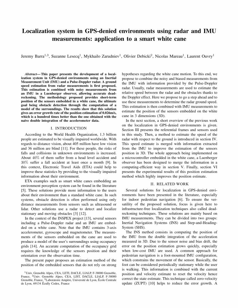
Three frames are used in this study, they are representedon figure 1. Under the hypothesis of a flat ground surface,they are defined as:• R0 = (O, ~x0, ~y0, ~z0) is a local reference frame in
which the sensors location has to be determined. Itsplan ( ~x0O~y0) is tangential with the ground.
• R = (O′, ~x, ~y, ~z = ~z0) is a referential attached to theuser of the white cane. Its origin is a projection of thecenter of gravity of the user on the ground. Its ~y axisis oriented in the direction of the user’s walk such thatthere is a rotation between R0 and R of angle ψ aroundthe ~z axis.
• Rb = (Ob, ~xb, ~yb, ~zb) is the referential attached to thebody of the sensors.
B. Inertial Measurement
An IMU usually consists in 3-axes sensors of 3 modalities,namely, accelerometer, gyroscope and magnetometer thatmeasure respectively the sensor acceleration, the angularvelocity and the local magnetic field in the sensor bodyreferential Rb. It has been shown in the literature thatthe measurements from these three sensors can be mergedto estimate the absolute orientation measurement of theIMU [4]. In the present work, the estimation of the IMUorientation is not addressed as the IMU mounted on the cane
Fig. 1: Frames of reference
already uses a state of the art attitude estimation algorithm.Therefore, the measurements in Rb can be expressed inR0 using a rotation matrix Rb0 defined from the estimatedattitude. For the position estimation of the sensors, the linearacceleration is expressed in the R0 frame. This correspondsto the acceleration measured by the accelerometers withoutthe influence of gravity.
C. Pulse-Doppler radar
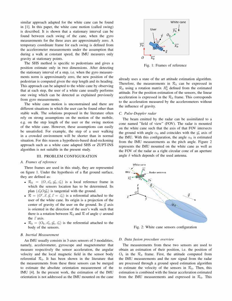
The beam emitted by the radar can be assimilated to acone named ”field of view” (FOV). The radar is mountedon the white cane such that the axis of that FOV intersectsthe ground with angle α0 and coincides with the ~yb axis ofthe IMU. With this configuration, the angle α0 is estimatedfrom the IMU measurements as the pitch angle. Figure 2represents the IMU mounted on the white cane as well asthe FOV of the radar as a right circular cone of an apertureangle δ which depends of the used antenna.
Fig. 2: White cane sensors configuration
D. Data fusion procedure overview
The measurements from these two sensors are used toobtain an estimation of their position, i.e. the position ofOb in the R0 frame. First, the attitude computed fromthe IMU measurements and the raw signal from the radarare processed through a ground speed estimation algorithmto estimate the velocity of the sensors in R0. Then, thisestimation is combined with the linear acceleration estimatedfrom the IMU measurements and expressed in R0. This

provides an estimation of the position of the sensors in frameR0. The whole procedure is illustrated in figure 3.
Fig. 3: Illustration of the sensors position estimation algo-rithm
IV. GROUND-SPEED ESTIMATION
The following section presents the proposed method toestimate the ground-speed v of the sensors mounted onthe white cane using raw Pulse-Doppler measurements. Thedifferent steps of this method are summarized on figure 4.
Fig. 4: Ground-speed estimation steps
A. From raw measurements to Range-Doppler map
The Pulse-Doppler radar emits coherent pulses at the pulserepetition frequency through its antenna. Each time a pulse issent by the radar, its energy is reflected by the environment,here, the ground. The reflection is returned to the antennawith a time delay:
τ = 2R
c⇔ R =
cτ
2(1)
R is the distance from the antenna to the ground and c =3.108m.s−1 is the electromagnetic wave speed in vacuum.According to (1), the time axis in the received time-domainsignal can be replaced by a range axis. This allows to expressthe energy received as a function of the distance from theradar to the obstacle (the ground), which is sampled in Mvalues, see figure 5.
Fig. 5: Single time-domain measurement
The acquisition of N time-domain measurements gives aN ×M time-domain matrix. A Fast Fourier Transform isthen applied to this matrix, leading to a frequency-domainspectrum, sometimes called Range-Doppler map [8] shownat figure 6.
Fig. 6: Range-Doppler map representation
B. Range-Doppler map analysis
Figure 6 shows that the frequency-domain spectrum isspread in the range and Doppler direction. The spreading inthe range direction is caused by the aperture δ of the FOVin the (~yO′~z) plan, see figure 7. In this plan, the FOV isdiscretized in K rays intersecting the ground with an angleαRi ∈ [α0 − δ
2 ;α0 +δ2 ], i = 1 : K.
Fig. 7: Discretization of the field-of-view (side view)
In this configuration, the ground speed vRiperceived along
a ray Ri is given by the formula:
vRi =cfRi
2ftrcos(αRi), i = 1 : K (2)
where ftr is the transmitted frequency, fRiis the Doppler
frequency received at a given range Ri and αRi is the anglebetween the ray Ri and the ground, see figure 7.
The spreading of the frequency-domain spectrum in theDoppler direction is due to the aperture angle δ in the planof the ground (~xO′~y). At a given point at range Ri (say Bon figure 8), a projection of the velocity is measured insteadof its real value measured at point A.
Fig. 8: Top view of the field-of-view
As a result, the Doppler frequency perceived for a givenrange Ri is not unique. The frequency corresponding to thenon-projected velocity will be found on the superior edgeof the frequency-domain spectrum, see Doppler frequenciesassociated to points A and B on figure 6. The Doppler
frequency fRiat a range Ri used in (2) is then determined
with a standard edge-detection technique based for instanceon the determination of the maximum gradient [2].
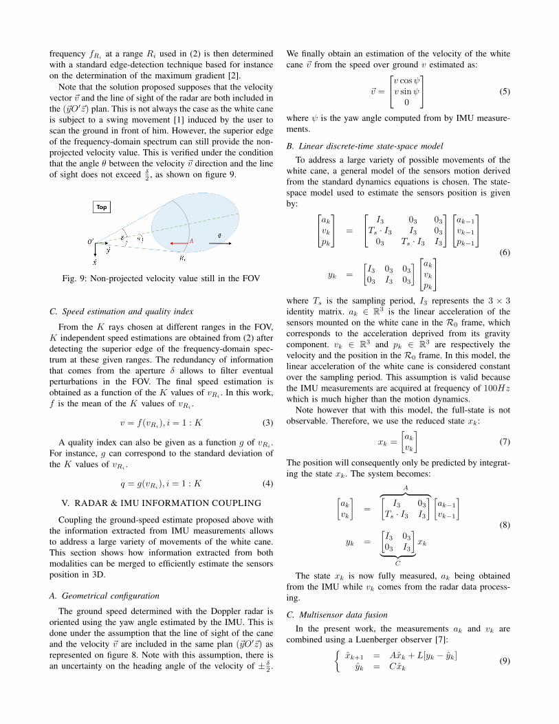
Note that the solution proposed supposes that the velocityvector ~v and the line of sight of the radar are both included inthe (~yO′~z) plan. This is not always the case as the white caneis subject to a swing movement [1] induced by the user toscan the ground in front of him. However, the superior edgeof the frequency-domain spectrum can still provide the non-projected velocity value. This is verified under the conditionthat the angle θ between the velocity ~v direction and the lineof sight does not exceed δ
2 , as shown on figure 9.
Fig. 9: Non-projected velocity value still in the FOV
C. Speed estimation and quality index
From the K rays chosen at different ranges in the FOV,K independent speed estimations are obtained from (2) afterdetecting the superior edge of the frequency-domain spec-trum at these given ranges. The redundancy of informationthat comes from the aperture δ allows to filter eventualperturbations in the FOV. The final speed estimation isobtained as a function of the K values of vRi
. In this work,f is the mean of the K values of vRi
.
v = f(vRi), i = 1 : K (3)
A quality index can also be given as a function g of vRi .For instance, g can correspond to the standard deviation ofthe K values of vRi
.
q = g(vRi), i = 1 : K (4)
V. RADAR & IMU INFORMATION COUPLING
Coupling the ground-speed estimate proposed above withthe information extracted from IMU measurements allowsto address a large variety of movements of the white cane.This section shows how information extracted from bothmodalities can be merged to efficiently estimate the sensorsposition in 3D.
A. Geometrical configuration
The ground speed determined with the Doppler radar isoriented using the yaw angle estimated by the IMU. This isdone under the assumption that the line of sight of the caneand the velocity ~v are included in the same plan (~yO′~z) asrepresented on figure 8. Note with this assumption, there isan uncertainty on the heading angle of the velocity of ± δ2 .
We finally obtain an estimation of the velocity of the whitecane ~v from the speed over ground v estimated as:
~v =
v cosψv sinψ0
(5)
where ψ is the yaw angle computed from by IMU measure-ments.
B. Linear discrete-time state-space model
To address a large variety of possible movements of thewhite cane, a general model of the sensors motion derivedfrom the standard dynamics equations is chosen. The state-space model used to estimate the sensors position is givenby: akvk
pk
=
I3 03 03Ts · I3 I3 0303 Ts · I3 I3
ak−1vk−1pk−1
yk =
[I3 03 0303 I3 03
]akvkpk
(6)
where Ts is the sampling period, I3 represents the 3 × 3identity matrix. ak ∈ R3 is the linear acceleration of thesensors mounted on the white cane in the R0 frame, whichcorresponds to the acceleration deprived from its gravitycomponent. vk ∈ R3 and pk ∈ R3 are respectively thevelocity and the position in the R0 frame. In this model, thelinear acceleration of the white cane is considered constantover the sampling period. This assumption is valid becausethe IMU measurements are acquired at frequency of 100Hzwhich is much higher than the motion dynamics.
Note however that with this model, the full-state is notobservable. Therefore, we use the reduced state xk:
xk =
[akvk
](7)
The position will consequently only be predicted by integrat-ing the state xk. The system becomes:
[akvk
]=
A︷ ︸︸ ︷[I3 03
Ts · I3 I3
] [ak−1vk−1
]
yk =
[I3 0303 I3
]︸ ︷︷ ︸
C
xk
(8)
The state xk is now fully measured, ak being obtainedfrom the IMU while vk comes from the radar data process-ing.
C. Multisensor data fusion
In the present work, the measurements ak and vk arecombined using a Luenberger observer [7]:{
xk+1 = Axk + L[yk − yk]yk = Cxk
(9)
where x is the estimated reduced state and yk is the vector ofsensors ”pseudo-measurements” at time k. L is the observergain, determined by pole-placement such that the matrix A−LC has all its eigenvalues inside the unit circle.
In the literature, the localization problem using on-boardsensors such as an IMU is usually solved with a Kalmanfilter, considering the equation 8 in a nondeterministic case:[
akvk
]=
[I3 03
Ts · I3 I3
] [ak−1vk−1
]+
[a ~wkv ~wk
]
yk =
[I3 0303 I3
]xk +
[a~vkv~vk
] (10)
where a ~wk, v ~wk and a~vk, v~vk are respectively the processand the measurement Gaussian white noises.
Such a solution has been also implemented and the resultsobtained were similar, see table I. The main drawback of theKalman filter solution, is that it requires more computationalworkload (e.g. computation of a gain at each samplingtime). As the proposed solution will be integrated on alow computing capability microcontroller with fixed-pointarithmetic, the Luenberger observer seems to be a betteroption from a computational point-of-view.
VI. RESULTS
A. Experimental setup
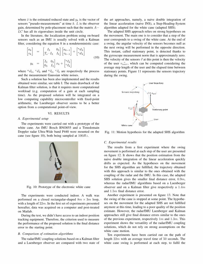
The experiments were carried out with a prototype of thewhite cane. An IMU Bosch BNO055 and a TimedomainDoppler radar Ultra-Wide band P440 were mounted on thecane (see figure 10), both being sampled at 100Hz.
Fig. 10: Prototype of the electronic white cane
The experiments were conducted indoor. A walk wasperformed on a closed rectangular-shaped 8m × 3m loop,with a length of 22m. In the first set of experiments presentedhereafter, data was acquired on a computer and post-treatedon Matlab.
During the test, we didn’t have access to an indoor positiontracking equipment. Therefore, the criterion used to measurethe performance of the proposed solution is the final distanceerror to the starting point.
B. Comparison of estimation algorithms
The radar/IMU coupling solutions based on a Kalman filterand a Luenberger observer are compared with two state of
the art approaches, namely, a naive double integration ofthe linear acceleration (naive INS), a Step-Heading-Systemalgorithm adapted for the white cane (adapted SHS).
The adapted SHS approach relies on strong hypotheses onthe movement. The main one is to consider that a step of theuser corresponds to a swing of the white cane. At the end ofa swing, the angular velocity of the sensors becomes null asthe next swing will be performed in the opposite direction.This instant, called stationary point, is detected thanks tothe gyroscope measurement norm that is approximately zero.The velocity of the sensors ~v at this point is then the velocityof the user ~vuser, which can be computed considering theaverage step length of the user and the elapsed time betweenstationary points. Figure 11 represents the sensors trajectoryduring the swing.
Fig. 11: Motion hypothesis for the adapted SHS algorithm
C. Experimental results
The results from a first experiment where the swingmovement is performed at each step of the user are presentedon figure 12. It shows that the position estimation from thenaive double integration of the linear acceleration quicklydrifts as expected. As the hypotheses on the movementfor the SHS algorithm are fulfilled, the trajectory obtainedwith this approach is similar to the ones obtained with thecoupling of the radar and the IMU. In this case, the adaptedSHS solution gives the smaller final distance error, 0.9m,whereas the radar/IMU algorithms based on a Luenbergerobserver and on a Kalman filter give respectively a 1.4mand 1.5m final distance error.
Another experiment is presented on figure 13. Note thatthe swing of the cane is stopped at some point. The hypothe-ses on the movement for the adapted SHS are not fulfilledanymore at this time, leading to a poor quality of the positionestimate. However, the radar/IMU Luenberger and Kalmanapproaches still give final distance errors similar to the onesof the previous experiment, respectively 1m and 1.3m. Thisexperiment shows the versatility of the radar/IMU couplingsolutions, which do not rely on strong assumptions on thewhite cane motion.
Ten experiments have been carried out on the path oflength 22m with an average travel time of 50 seconds. Thewhite cane swing is performed at each step, to fulfil the
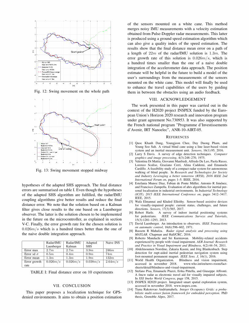
Fig. 12: Swing movement on the whole path
Fig. 13: Swing movement stopped midway
hypotheses of the adapted SHS approach. The final distanceerrors are summarised on table I. Even though the hypothesesof the adapted SHS algorithm are fulfilled, the radar/IMUcoupling algorithms give better results and reduce the finaldistance error. We note that the solution based on a Kalmanfilter gives close results to the one based on a Luenbergerobserver. The latter is the solution chosen to be implementedin the future on the microcontroller, as explained in sectionV-C. Finally, the error growth rate for the chosen solution is0.026m/s which is a hundred times better than the one ofthe naive double integration approach.
Radar/IMULuenberger
Radar/IMUKalman
AdaptedSHS
Naive INS
Error max 2.7m 2.7m 3.9m 246mError sd σ 0.5m 0.4m 0.9m 74mError mean 1.3m 1.3m 1.9m 132mError growthrate
0.026m/s 0.026m/s 0.038m/s 2.64m/s
TABLE I: Final distance error on 10 experiments
VII. CONCLUSION
This paper proposes a localization technique for GPS-denied environments. It aims to obtain a position estimation
of the sensors mounted on a white cane. This methodmerges noisy IMU measurements with a velocity estimationobtained from Pulse-Doppler radar measurements. This latteris produced using a ground speed estimation algorithm whichcan also give a quality index of the speed estimation. Theresults show that the final distance mean error on a path ofa length of 22m of the radar/IMU solution is 1.3m. Theerror growth rate of this solution is 0.026m/s, which isa hundred times smaller than the one of a naive doubleintegration of the accelerometer data approach. The positionestimate will be helpful in the future to build a model of theuser’s surroundings from the measurements of the sensorsmounted on the white cane. This model will finally be usedto enhance the travel capabilities of the users by guidingthem in between the obstacles using an audio feedback.
VIII. ACKNOWLEDGEMENTThe work presented in this paper was carried out in the
context of the H2020 project INSPEX funded by the Euro-pean Union’s Horizon 2020 research and innovation programunder grant agreement No.730953. It was also supported bythe French national program ”Programme d’Investissementsd’Avenir, IRT Nanoelec”, ANR-10-AIRT-05.
REFERENCES
[1] Quoc Khanh Dang, Youngjoon Chee, Duy Duong Pham, andYoung Soo Suh. A virtual blind cane using a line laser-based visionsystem and an inertial measurement unit. Sensors, 16(1):95, 2016.
[2] Larry S Davis. A survey of edge detection techniques. Computergraphics and image processing, 4(3):248–270, 1975.
[3] Valentina Di Mattia, Giovanni Manfredi, Alfredo De Leo, Paola Russo,Lorenzo Scalise, Graziano Cerri, Alina Caddemi, and EmanueleCardillo. A feasibility study of a compact radar system for autonomouswalking of blind people. In Research and Technologies for Societyand Industry Leveraging a better tomorrow (RTSI), 2016 IEEE 2ndInternational Forum on, pages 1–5. IEEE, 2016.
[4] Estefania Munoz Diaz, Fabian de Ponte Muller, Antonio R Jimenez,and Francisco Zampella. Evaluation of ahrs algorithms for inertial per-sonal localization in industrial environments. In Industrial Technology(ICIT), 2015 IEEE International Conference on, pages 3412–3417.IEEE, 2015.
[5] Wafa Elmannai and Khaled Elleithy. Sensor-based assistive devicesfor visually-impaired people: current status, challenges, and futuredirections. Sensors, 17(3):565, 2017.
[6] Robert Harle. A survey of indoor inertial positioning systemsfor pedestrians. IEEE Communications Surveys and Tutorials,15(3):1281–1293, 2013.
[7] David Luenberger. An introduction to observers. IEEE Transactionson automatic control, 16(6):596–602, 1971.
[8] Bassem R Mahafza. Radar signal analysis and processing usingMATLAB. Chapman and Hall/CRC, 2016.
[9] Roberto Manduchi and Sri Kurniawan. Mobility-related accidentsexperienced by people with visual impairment. AER Journal: Researchand Practice in Visual Impairment and Blindness, 4(2):44–54, 2011.
[10] Abdelmoumen Norrdine, Zakaria Kasmi, and Jorg Blankenbach. Stepdetection for zupt-aided inertial pedestrian navigation system usingfoot-mounted permanent magnet. IEEE Sens. J, 16(1), 2016.
[11] World Health Organization. Blindness and vision impairment,accessed in november 2018. www.who.int/en/news-room/fact-sheets/detail/blindness-and-visual-impairment.
[12] Stefano Pisa, Emanuele Piuzzi, Erika Pittella, and Giuseppe Affronti.A fmcw radar as electronic travel aid for visually impaired subjects.In XXI Imeko World Congress, page 158, 2015.
[13] INSPEX H2020 project. Integrated smart spatial exploration system,accessed in november 2018. www.inspex.com.
[14] Tiana Rakotovao Andriamahefa. Integer Occupancy Grids: a proba-bilistic multi-sensor fusion framework for embedded perception. PhDthesis, Grenoble Alpes, 2017.