Embed Size (px)
Citation preview

COMPDYN 2013
4th ECCOMAS Thematic Conference on
Computational Methods in Structural Dynamics and Earthquake Engineering
M. Papadrakakis, N.D.Lagaros, V. Plevris (eds.)
Kos Island, Greece, 12–14 June 2013
LOCAL EFFECTS IN THE SEISMIC DESIGN OF RC FRAME
STRUCTURES WITH MASONRY INFILLS
S. Hak1, P. Morandi
2, and G. Magenes
2
1 University of Pavia
Via Ferrata 1, Pavia, Italy
2 University of Pavia and EUCENTRE
Via Ferrata 1, Pavia, Italy
[email protected], [email protected]
Keywords: Local Effects, RC Frames, Masonry Infills, Shear Design, Nonlinear Analyses.
Abstract. For the prevention of local effects that may occur on the load-bearing elements of
newly designed masonry infilled RC frames, additional measures are foreseen in modern
seismic design codes. In particular, European code regulations impose special detailing and
confinement requirements for structural elements in RC frames with adherent masonry infills.
Moreover, the verification of adjacent columns for increased shear demands is required, es-
timated based on approximate values of horizontal shear strength of the infill, and through
the application of capacity design principles along the contact length. With the aim to verify
the efficiency of the current design approach and provide additional recommendations re-
lated to local effects due to the presence of masonry infills in RC frames, in this study a series
of nonlinear dynamic analyses on typical newly designed building configurations with differ-
ent masonry infill typologies of varying strength and stiffness properties has been performed
at increasing levels of seismicity. The analyses are carried out using a simple numerical
model representing the masonry infill as a single diagonal strut. Although such model cannot
directly capture the local effects in the contact region, it allows, a posteriori, the calculation
of effective shear demands on the columns. For a number of considered prototype buildings, a
comparison of effective shear demands obtained from analyses and shear design forces re-
quired by the code has been carried out. Furthermore, a simplified procedure for the verifica-
tion of columns in RC frames exposed to increased shear demands due to the presence of
masonry infills as a function of expected inter-storey drift demands has been proposed. Hence,
starting from existing code recommendations, the given method allows the evaluation of shear
design forces in compliance with effective shear demands, accounting for different masonry
infill typologies, the position of the infill along the height of the building and the seismic
ground motion intensity.

S. Hak, P. Morandi and G. Magenes
1 INTRODUCTION
The possible occurrence of local effects on structural elements of RC frames with masonry
infills is widely recognized and has repeatedly been supported by field evidence from recent
earthquake events in Italy. After the April 2009 earthquake in Abruzzo (L’Aquila), extensive
damage has been reported on non-structural masonry infills, see e.g. [1]; moreover, in many
cases the poor behaviour or even failure of structural elements in RC frames has been identi-
fied [2], often caused by adverse effects due to the presence of masonry infills. Also following
the most recent seismic event that has stroked the region of Emilia in May 2012, examples of
local effects on the structural elements of infilled frames have been reported [3, 4, 5], as illus-
trated in Figure 1.
Figure 1: Examples of local effects reported after the May 2012 Emilia earthquake
a) Magenes et al. 2012 [3]; b) Manzini and Morandi 2012 [4].
In particular, local damage and eventually brittle failure can commonly be caused on col-
umns that are in partial contact with masonry infill walls, causing a reduction of the clear
height of the column and, hence, inducing increased shear and displacement demands. As dis-
cussed in previous studies [6], the problem of laterally restrained captive columns, particu-
larly vulnerable to seismic actions, should possibly be pursued through adequate measures in
the conceptual design of new buildings. However, detrimental effects on columns of RC
frame structures can be caused by the interaction with masonry infills also in the case of full
contact along the height of the column, in particular when masonry infill typologies of high
strength and stiffness properties are used in construction, and/or when the infill is located only
on one side of the column. Specifically, additional concentrated shear demands may be im-
posed on the column at its ends in the region of contact with the masonry infill due to the ac-
tivation of compressive diagonal strut forces. For the prevention of such local effects in newly
designed structures, with infills adherent to the RC frame, additional measures are foreseen in
modern seismic design codes, such as Eurocode 8 – Part 1 [7].
The application of the recommended simplified approaches to practical design cases re-
veals, however, the fact that increased shear design forces are imposed independently of the
design conditions and of the position of the structural element in the building, even though the
corresponding column shear may vary significantly. In this study the current European design
provisions for RC frames have been applied to a number of prototype building configurations,
including the additional measures for infilled structures by means of increased shear design
forces, capacity design principles and detailing rules, in order to detect the governing design
situations for different peak ground accelerations and design ductility classes. Subsequently, a
b) a)

S. Hak, P. Morandi and G. Magenes
number of nonlinear time-history analyses of the RC frames with masonry infills of increas-
ing strength and stiffness properties has been carried out, with the aim of determining effec-
tive shear demands imposed on the columns and to propose improved shear design
verifications as a function of in-plane drift demands imposed on the structure.
2 DESIGN FOR THE PREVENTION OF ADVERSE LOCAL EFFECTS
2.1 Current European Design Provisions
According to current European provisions for the design of structures for earthquake resis-
tance Eurocode 8 – Part 1 [7], besides irregularities in plan and elevation due to the presence
of infills that may adversely influence the global behaviour of RC frames, possible local ef-
fects due to the frame-infill interaction need to be taken into account. Therefore, special de-
tailing and confinement requirements for structural elements in RC frames with adherent
masonry infills, as well as a verification of the adjacent columns for approximate increased
shear demands are imposed. Specifically, due to the particular vulnerability of infills in the
ground floor, where seismically induced irregularity may be expected, if a more precise
method is not used, the entire length of all columns should be considered as critical region
(Figure 2a) and consequently, the relevant confinement and detailing rules have to be satisfied.
The same requirement applies in the case when infills extend over the entire column height lt,
but only on one side of the column (Figure 2b), as well as for columns which are in contact
with adjacent infills along just a part of their total height lt (Figure 2c), inducing the presence
of a clear portion of the column height lcl < lt. In this latter case, the consequences of the de-
creased shear span of the column due to the horizontal restraint by the infills (Figure 3) should
be covered in addition. Therefore, the shear demand has to be determined from the provided
column resistance MC,Rd following the capacity design principle applied over the clear height
lcl (Equation 1), adopting an overstrength coefficient γRd = 1.1 for ductility class medium
(DCM) and γRd = 1.3 for ductility class high (DCH).
Figure 2: a) Critical length of columns in the ground floor;
b) Critical length of columns in full contact with the infill on one side;
c) Critical length of columns in partial contact with the infill.
Figure 3: Decreased column shear span ratio due to partial contact with the infill
cl
RdC
RdclEdl
MγV
,
,
2= (1)
a) b) c)

S. Hak, P. Morandi and G. Magenes
Further safety verifications present in the European code regulations rely upon the com-
mon simplification of the masonry infill action based on an equivalent strut model, represent-
ing the diagonal portion of the infill by a compressive strut. The requirement that is of
particular interest for this study indicates that the contact length lc of the column, over which
the diagonal strut force of the infill acts on the column causing a local pressure fs and intro-
ducing a concentration of forces (Figure 4a), should be verified in shear for the smaller of the
following two shear forces:
a) the horizontal component Fw,s,hor of the diagonal strut force Fw,s of the infill, that can
be assumed to be equal to the shear strength of the panel;
b) the shear force VC,Ed determined following the capacity design principle (Equation 2),
assuming that the flexural column capacity develops at the ends of the contact length lc
(Figure 4b).
c
RdCRdEdC
l
MγV
,,
2= (2)
Figure 4: a) Application of the diagonal strut action on the column within the contact length;
b) Flexural column capacity developed at the ends of the contact length
2.2 Interpretation of Design Requirements
According to the code, the horizontal component Fw,s,hor of the diagonal strut force Fw,s can
be assumed to be equal to the horizontal shear strength of the panel, estimated on the basis of
the shear strength of bed joints. Since no explicit recommendations related to the evaluation
of the shear strength of the bed joints are specified in the code, it could be reasonable to use
the expression included in the Eurocode 6 – Part 1 [8], commonly assumed for load-bearing
masonry walls, considering the shear strength of the bed joints equal to the initial shear
strength under zero compressive stress fv0. Hence, for a masonry infill of thickness tw, length
lw and shear strength fv = fv0 the corresponding horizontal strength Fw,s,hor,1 may be estimated
as given in Equation 3.
wwvhorsw ltfF 01,,, = (3)
A number of more refined models for the evaluation of the masonry infill strength and cor-
responding equivalent diagonal strut forces is available. Some of these models are able to ac-
count for different failure mechanisms typically observed on masonry panels and usually
supported by experimental studies, e.g. as proposed by Decanini et al. [9] for compression at
a) b)

S. Hak, P. Morandi and G. Magenes
the centre, compression at the corners, shear sliding and diagonal tension. The horizontal
component of the corresponding equivalent strut strength Fw,s,hor,2 can be expressed by Equa-
tion 4, where fm’ indicates the strength associated with the critical failure mode, tw the thick-
ness of the infill, bw the width and θ the inclination of the equivalent strut.
θcos'2,,, wwmhorsw btfF = (4)
The evaluation of local shear design forces can eventually be influenced by the choice of
the contact length lc, over which the diagonal strut force of the infill acts on the column, since
applying the capacity design principle given in Equation 2, for larger values of contact length
lower shear demands VC,Ed are obtained and may be governing with respect to the horizontal
strength of the panel Fw,s,hor. As specified in the code, unless a more accurate estimation is
made taking into account the elastic properties and the geometry of the infill and the column,
the strut width may be assumed to be a fixed fraction of the length of the panel diagonal. Pau-
lay and Priestley have suggested that a conservatively high value of the diagonal strut width
bw equal to one quarter of the panel diagonal dw may be assumed [10]. However, for the defi-
nition of the equivalent strut width a series of more refined approaches are available in litera-
ture. For instance, according to the model proposed by Decanini et al. [9], the equivalent strut
width is evaluated as a function of a relative stiffness parameter to account for the interaction
between the frame and the infill. A similar approach is adopted in Mainstone’s model [11],
suggested also in other studies, and recommended e.g. in the work by Fardis for the applica-
tion of design provisions according to Eurocode 8 [6]. Even though it is stated in the code that
the contact length should be assumed to be equal to the full vertical width of the diagonal strut
of the infill bw, this requirement should be interpreted depending on the strut model that is be-
ing adopted and the corresponding failure modes considered. Herein, the contact length has
been evaluated following the model by Paulay and Priestley [10] and Decanini et al. [9], as-
suming the contact length equal to 0.5bw/cos θ (see Figure 5a) and according to the model by
Mainstone [11], assuming the contact length equal to bw/cos θ (see Figure 5b).
Figure 5: Evaluation of the contact length: a) lc = 0.5bw/cos θ; b) lc = bw/cos θ
3 NUMERICAL STUDY
3.1 Design and Modelling Assumptions
For the needs of this study, as part of a wider analytical campaign, a number of numerical
analyses has been carried out on different typologies of RC frames, newly designed according
to current European (Eurocode 8 – Part 1 [7]) and Italian national code provisions (NTC08
a) b)
S. Hak, P. Morandi and G. Magenes
[12]). Specifically, 3-storey, 6-storey and 9-storey frames have been considered, designed for
two different ductility classes, namely medium (DCM) and high (DCH), and five different
design peak ground accelerations, i.e. 0.05g, 0.10g, 0.15g, 0.25g and 0.35g, resulting in 30
different bare frame configurations. A more detailed description of the frame design proce-
dure is given in the work by Morandi et al. [13].
In summary, as recommended in the code provisions for the design of regular structures,
the design has been carried out for bare frame configurations, based on linear analyses of elas-
tic models, satisfying capacity design principles, strength and ductility requirements as well as
displacement limitations. Subsequently, time-history analyses have been carried out on
nonlinear models of the infilled frame typologies, using the structural analysis program
Ruaumoko [14], adopting the concentrated plasticity modelling approach for structural ele-
ments and representing the masonry infills by a simple single-strut model. Even though in
such simplified model the local effects due to the presence of masonry infills cannot be cap-
tured directly, induced effective column shear demands have been evaluated a posteriori from
the diagonal strut force. In order to evaluate the strength and stiffness properties of the
equivalent strut, the model proposed by Decanini et al. [9] has been adopted, while the hys-
teretic rule introduced by Crisafulli [15] has been calibrated on experimental test results and
used to model the nonlinear cyclic behaviour of the infill. The local effects have been studied
on the external columns of fully infilled frame typologies for three different types of masonry
infills with increasing strength and stiffness properties, representing weak (T1), medium (T2)
and strong infill (T3). Further details on the modelling assumptions and the considered ma-
sonry infill typologies are given in the work by Hak et al. [16].
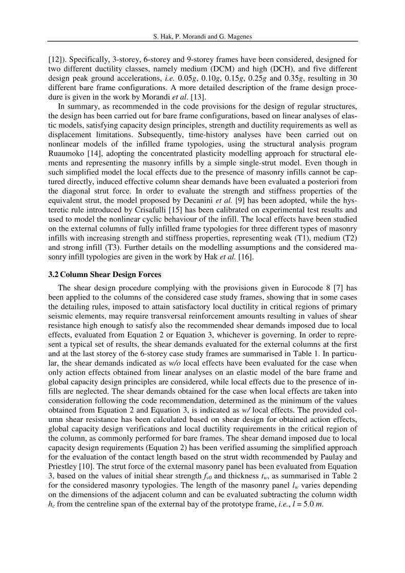
3.2 Column Shear Design Forces
The shear design procedure complying with the provisions given in Eurocode 8 [7] has
been applied to the columns of the considered case study frames, showing that in some cases
the detailing rules, imposed to attain satisfactory local ductility in critical regions of primary
seismic elements, may require transversal reinforcement amounts resulting in values of shear
resistance high enough to satisfy also the recommended shear demands imposed due to local
effects, evaluated from Equation 2 or Equation 3, whichever is governing. In order to repre-
sent a typical set of results, the shear demands evaluated for the external columns at the first
and at the last storey of the 6-storey case study frames are summarised in Table 1. In particu-
lar, the shear demands indicated as w/o local effects have been evaluated for the case when
only action effects obtained from linear analyses on an elastic model of the bare frame and
global capacity design principles are considered, while local effects due to the presence of in-
fills are neglected. The shear demands obtained for the case when local effects are taken into
consideration following the code recommendation, determined as the minimum of the values
obtained from Equation 2 and Equation 3, is indicated as w/ local effects. The provided col-
umn shear resistance has been calculated based on shear design for obtained action effects,
global capacity design verifications and local ductility requirements in the critical region of
the column, as commonly performed for bare frames. The shear demand imposed due to local
capacity design requirements (Equation 2) has been verified assuming the simplified approach
for the evaluation of the contact length based on the strut width recommended by Paulay and
Priestley [10]. The strut force of the external masonry panel has been evaluated from Equation
3, based on the values of initial shear strength fv0 and thickness tw, as summarised in Table 2
for the considered masonry typologies. The length of the masonry panel lw varies depending
on the dimensions of the adjacent column and can be evaluated subtracting the column width
hc from the centreline span of the external bay of the prototype frame, i.e., l = 5.0 m.
S. Hak, P. Morandi and G. Magenes
6-storey Shear demand Column
shear
resistance
Shear demand
Column
shear
resistance
Local effects
Local effects
hc w/o w/
hc w/o w/
T1 T2 T3
T1 T2 T3
PGA DCM [m] [kN] [kN] [kN] [kN] [kN] DCM [m] [kN] [kN] [kN] [kN] [kN]
0.05g
1st st.
0.45 202.8 200.2 295.8 409.5 422.6
6th st.
0.35 96.9 204.6 302.3 331.1 230.0
0.10g 0.45 202.8 200.2 295.8 409.5 422.6 0.35 96.9 204.6 302.3 331.1 230.0
0.15g 0.45 202.8 200.2 295.8 409.5 422.6 0.35 96.9 204.6 302.3 331.1 230.0
0.25g 0.45 202.8 200.2 295.8 409.5 422.6 0.35 96.9 204.6 302.3 331.1 230.0
0.35g 0.50 300.0 198.0 292.5 405.0 535.0 0.40 116.9 202.4 299.0 397.5 323.6
DCH
DCH
0.05g
1st st.
0.45 249.1 200.2 295.8 409.5 422.6
6th st.
0.35 123.7 204.6 302.3 406.8 237.7
0.10g 0.45 249.1 200.2 295.8 409.5 422.6 0.35 123.7 204.6 302.3 406.8 237.7
0.15g 0.45 249.1 200.2 295.8 409.5 422.6 0.35 123.7 204.6 302.3 406.8 237.7
0.25g 0.45 249.1 200.2 295.8 409.5 422.6 0.35 123.7 204.6 302.3 406.8 237.7
0.35g 0.45 249.1 200.2 295.8 409.5 422.6 0.35 123.7 204.6 302.3 406.8 237.7
Table 1: Column shear demands (w/o and w/ local effects) and shear resistance of 6-storey prototype frames
T1 T2 T3
fv0 [MPa] 0.44 0.25 0.30
tw [mm] 0.10 0.26 0.30
Table 2: Masonry infill initial shear strength and thickness
In the case of external columns, the EC8 recommendations state that the critical region
should be taken equal to the full height of the column since the infill is present only on one
side. It can be noticed that in some cases a high shear resistance may be achieved due to the
given detailing requirements in order to obtain the needed ductility in critical regions, or due
to the choice of large cross sections required by other design issues, such as the limitation of
in-plane displacement demands. Hence, the additional shear demand due to the presence of
infills may not always govern the shear design, above all at the bottom storeys of taller build-
ings and/or in the case of high seismicity. At the same time, however, it can be observed that
in the upper storeys, in particular in buildings of lower height and/or in the case of lower or
intermediate seismicity, shear demands imposed due to the presence of infills may exceed
significantly the values obtained from other design criteria. Following the current design pro-
cedure, shear demands induced by local effects due to the presence of infills are determined
independently of different design conditions and the position of the infill along the height of
the building, although the assumption of equal maximum strut forces for all verifications may
not always be rational.
3.3 Nonlinear Analyses Results
In order to determine the variation of possible shear effects, imposed under seismic actions,
along the height of a building as a function of the considered design parameters, i.e., design
peak ground acceleration, ductility class and building height, nonlinear time-history analyses
of the infilled frame models have been performed at different levels of seismicity, correspond-
ing to the considered levels of design peak ground acceleration. The analyses have been car-
ried out for a set of ten scaled natural earthquake records selected matching the average
earthquake response spectrum with the design spectrum [13]. Hence, maximum response
quantities have been determined for each record and subsequently a corresponding average
value has been evaluated. In particular, the maximum horizontal strut actions achieved in the
external masonry panels and the maximum effective shear forces on the external columns of
each storey of the fully infilled case study frames have been evaluated.

S. Hak, P. Morandi and G. Magenes
Activated Strut Forces. The average maximum horizontal component of the activated
strut force Fw,s,hor,act, see Equation 5 where i indicates the i-th acceleration record, obtained
from analyses for each storey of each prototype frame, for the three considered infill typolo-
gies, has been normalised, as given by Equation 6, to the corresponding horizontal resistance
of the strut Fw,s,hor,2, determined from the governing failure mode according to the model by
Decanini et al. [9] (Equation 4). The percentage of strut force activation aw and its variation
along the building height, for infills in the 6-storey frame typologies, designed for ductility
class medium, is shown in Figure 6. The position of the infill along the height of the building
is represented by the ratio hn of the distance from the foundation of the building to the centre
of mass of the infill hw and the total height of the building H as given by Equation 7.
∑=
=
10
1
max,,,,,,,10
1
i
ihorswacthorsw FF (5)
1002,,,
,,,⋅=
horsw
acthorsww
F
Fa
(6)
H
hh w
n = (7)
A significant reduction of the strut force amplitude can be observed in the upper quarter of
the building height. Moreover, the results show clearly the considerable increase of activated
strut forces with increasing ground motion intensity. Additionally, a reduction of the strut
force activation can be noticed for increasing strength and stiffness properties of the consid-
ered masonry infills.
Figure 6: Strut force activation in 6-storey DCM frames
Effective Column Shear Demands. The effective shear demand Vw,C imposed on a column
due to the strut action (see Figure 4a) can be approximately evaluated a posteriori as the dif-
ference between the horizontal component of the activated strut force Fw,s,hor,act and the corre-
sponding shear in the column VC, as given in Equation 8. For the considered prototype frames,
the average maximum effective shear demand Vw,C,ref imposed on each column has been
evaluated from Equation 9.
CacthorswCw VFV −= ,,,,
(8)

S. Hak, P. Morandi and G. Magenes
∑=
=
10
1
max,,,,,10
1
i
iCwrefCw VV (9)
The obtained results indicate that the effective column shear demands are regularly slightly
lower than the activated strut forces; hence the verification of the column for the activated
strut force rather than the effective column shear demand can be considered safe-sided, but
not too conservative. In fact, also the code provisions rationally require the verification of the
column for the strut force action neglecting the eventual presence of shear forces in the col-
umns, considering the strut, however, always fully activated.
Comparison: Design Shear Forces, Activated Strut Forces, Effective Shear Demands. Summarising the presented results, a comparison of the column design shear forces obtained
following the code recommendations, and the shear forces obtained from nonlinear time-
history analyses, for two selected case studies, namely the 6-storey fame designed for peak
ground accelerations of 0.10g and 0.25g in ductility class medium, are shown in Figure 7. In
particular, as summarised in Table 3, the graphs include shear design forces obtained from
locally applied capacity design principles using three different models for the evaluation of
the contact length, horizontal strut forces calculated following two different approaches, acti-
vated strut forces and effective shear demands from nonlinear analyses and design shear
forces that would be imposed due to action effects evaluated from linear analyses and from
capacity design principles, without considering any local effects.
Column shear demand Description
1 VC,Ed Capacity design shear force Equation 2
Contact length lc - Mainstone [11], Figure 5b
2 VC,Ed Capacity design shear force Equation 2
Contact length lc - Paulay and Priestley [10], Figure 5a
3 VC,Ed Capacity design shear force Equation 2
Contact length lc - Decanini et al. [9], Figure 5a
4 Fw,s,hor,1 Horizontal strut resistance (simplified) Equation 3, Initial shear strength criterion
5 Fw,s,hor,2 Horizontal strut resistance (refined) Equation 4, Decanini et al. [9]
6 Fw,s,hor,act Activated horizontal strut force Equation 5, from nonlinear analyses
7 Vw,C,ref Effective shear demand Equation 9, from nonlinear analyses
8 VC,Ed,0 Design shear demand w/o local effects From linear analysis and global capacity design
Table 3: Design and effective column shear demands
The design shear forces obtained applying the capacity design along the contact length
evaluated following the simplified model proposed by Paulay and Priestley [10] vary only due
to the difference in moment resistance of adjacent column elements, while the other two mod-
els considered for the evaluation of the strut width result in increasing values of shear de-
mands for increasing masonry strength and stiffness. Due to the significant influence of the
relative stiffness of frame and infill on the contact length evaluated following the model pro-
posed by Decanini et al. [9], the corresponding shear forces are considerably lower compared
to the other models, especially where the relative stiffness of the masonry is low compared to
that of the frame, as in the case for weak masonry infills and/or in lower storeys, due to larger
column dimensions. However, independently of the strut model, the capacity design shear
force from Equation 2 in comparison with the simplified horizontal resistance of the strut

S. Hak, P. Morandi and G. Magenes
from Equation 3, results to be governing only for the strong infill (typology T3) in some of
the upper storeys, where columns have smaller dimensions and a lower bending capacity.
Figure 7: Design shear forces, activated strut forces and effective shear demands for 6-storey frames
a) 0.10g DCM; b) 0.25g DCM
Considering a refined evaluation of the strut resistance, including the possible occurrence
of different failure modes, as for example based on the model by Decanini et al. [9] (Equation
4), the local shear imposed due to the strut action can be identified as the governing value for
all considered case studies. Besides that, such model results in 30-40 % lower values of ma-
sonry infill strength compared to the values obtained from the initial strength criterion (Equa-
tion 3), depending on the typology. Therefore, it can also be noticed that for all considered
infill strength and stiffness properties, the resistance based on the initial shear strength crite-
rion exceeds significantly the effective shear demands on the columns evaluated from time-
history analyses based on the more refined infill model. This fact is particularly pronounced if
the maximum strut force has been only partially activated, such as in the case of lower earth-
quake actions, stronger infills and in upper storeys.
4 CONCLUSIONS AND IMPLICATIONS FOR DESIGN
4.1 Shear Demands in Function of Inter-storey Drifts
Having in mind the considerable variation of shear demands imposed due to the presence
of masonry infills, the application of a refined procedure for the evaluation of design forces
accounting for local effects is envisaged. It can be shown that the activation of the strut force
aw in each storey of the infilled frame, as presented in Figure 6 e.g. for varying peak ground

S. Hak, P. Morandi and G. Magenes
accelerations and infill typologies in the case of DCM 6-storey building configurations, can
be expressed as a function of a single parameter, namely the average inter-storey drift demand
δw imposed on the infilled frame. Accordingly, the complete set of results for all considered
prototype frames showing the strut activation obtained from nonlinear time-history analyses
can be summarised as given in Figure 8a. The obtained relation can be represented approxi-
mately, for example, by polynomial and linear or linear segments, as shown in Figure 8b, and
expressed by Equation 10 and Equation 11, respectively. Such simplified expressions may be
used in the design of infilled RC frames in order to determine the expected activation of the
strut action.
Figure 8: Strut force activation vs. average drift of the infilled frame: a) TH results; b) Possible approximations
>
<+−+−=
006.0,0.1
006.0,7.92.435.1020.1265.622345
w
wwwwwwwa
δ
δδδδδδ (10)
>
≤<+
≤<+
≤
=
006.0,0.1
006.0002.0,85.025
002.0001.0,30.0300
001.0,600
w
ww
ww
ww
wa
δ
δδ
δδ
δδ
(11)
4.2 Refined Shear Design for Local Effects
Based on the presented results, a possible refinement of the current design procedure for
the evaluation of local effects due to the presence of masonry infills in RC frames may be in-
troduced, assuming that the inter-storey drifts of the infilled frame δw can be predicted. Hence,
the corresponding expected strut force activation aw can be evaluated from a simplified ex-
pression, such as Equation 10 or Equation 11. Given that the design of regular infilled frame
structures is commonly carried out on bare frames, the evaluation of expected drifts of the
infilled frame is not a straightforward task and clearly depends, besides on the design proper-
ties of the bare frame, such as the building configuration, design seismic action and ductility
class, also on the typology and distribution of the masonry infill. Assuming conservatively
that the maximum shear demand on the column equals the activated horizontal component of
the strut force rather than the effective column shear force (see Equation 8 and Equation 9),
the shear demand can be estimated as given in Equation 12.
horwwEdC FaV ,, = (12)

S. Hak, P. Morandi and G. Magenes
The maximum horizontal strut force Fw,hor should possibly be evaluated from a model ac-
counting for different infill failure modes (Equation 4) or may be estimated following other
approaches (e.g. such given by Equation 3). Finally, the capacity design verification has to be
accomplished along the contact length in order to determine the governing shear demand.
Even though different values of the contact length lc can be obtained from different strut mod-
els, the design is not significantly influenced by this choice and the application of a simple
model, such as assuming the diagonal strut width bw equal to one quarter of the panel diagonal
dw, as suggested by Paulay and Priestley [10], can be considered satisfactory.
ACKNOWLEDGEMENTS
The research upon which this work is based is carried out at the University of Pavia and at
EUCENTRE Pavia, and it is sponsored by ANDIL Assolaterizi and by the Executive Project
DPC-RELUIS 2010-2013, task AT2-1.3. The financial support of these sponsors is gratefully
acknowledged.
REFERENCES
[1] F. Braga, V. Manfredi, A.Masi, A.Salvatori, M. Vona, Performance of nonstructural
elements in RC buildings during the L’Aquila, 2009 earthquake, Bulletin of Earthquake
Engineering, 9, 307–324, 2011.
[2] P. Ricci, V. Manfredi, F. De Luca, G.M. Verderame, 6th
April 2009 L’Aquila
earthquake, Italy: reinforced concrete building performance, Bulletin of Earthquake
Engineering, 9, 285–305, 2011.
[3] G. Magenes, S. Bracchi, F. Graziotti, M. Mandirola, C.F. Manzini, P. Morandi, M.
Palmieri, A. Penna, A. Rosti, M. Rota, M. Tondelli, Preliminary damage survey to
masonry structures after the May 2012 Emilia earthquakes, v.1,
http://www.eqclearinghouse.org/2012-05-20-italy-it, 2012.
[4] C.F. Manzini, P. Morandi, Rapporto preliminare sulle prestazioni ed i danneggiamenti
agli edifici in muratura portante moderni a seguito degli eventi sismici emiliani del
2012, v.1, Eucentre, http://www.eqclearinghouse.org/2012‐05‐20‐italy/, 2012.
[5] L.D. Decanini, D. Liberatore, L. Liberatore, L. Sorrentino, Preliminary Report on the
2012, May 20, Emilia Earthquake, v.1, http://www.eqclearinghouse.org/2012-05-20-
italy-it/, 2012.
[6] M.N. Fardis, Seismic design issues for masonry-infilled RC frames, Proceedings of
First European Conference on Earthquake Engineering and Seismology, Geneva,
Switzerland, 2006.
[7] CEN Eurocode 8 - Design of structures for earthquake resistance - Part 1: General rules,
seismic actions and rules for buildings, European Committee for Standardisation, EN
1998-1:2004, Brussels, 2004.
[8] CEN Eurocode 6 - Design of masonry structures - Part 1-1: Common rules for
reinforced and unreinforced masonry structures, European Committee for
Standardisation, ENV 1996-1-1:2004, Brussels, 2005.
[9] L.D. Decanini, S.H. Bertoldi, C. Gavarini, Telai tamponati soggetti ad azione sismica,
un modello semplificato: confronto sperimentale e numerico (in Italian). Atti del 6
Convegno Nazionale ANIDIS, Perugia, Italy, 1993.

S. Hak, P. Morandi and G. Magenes
[10] T. Paulay, M.J. Priestley, Seismic design of reinforced concrete and masonry buildings.
John Wiley & Sons, USA, 1992.
[11] R.J. Mainstone, On the stiffnesses and strengths of infilled frames, Proc. of the
Institution of Civil Engineers, Supp.(iv), 57–90, 1971.
[12] NTC08 Decreto Ministeriale 14 Gennaio 2008: Norme tecniche per le costruzioni,
Ministero delle Infrastrutture. S.O. n.30 alla G.U. del 4.2.2008, No. 29, 2008.
[13] P. Morandi, S. Hak, G. Magenes, Comportamento sismico delle tamponature in laterizio
in telai in c.a.: analisi numeriche su edifici ed implicazioni progettuali (in Italian), Atti
del XIV convegno nazionale ANIDIS, Bari, Italy, 2011.
[14] A.J. Carr, Ruaumoko Manual, University of Canterbury, Cristchurch, New Zealand,
2007.
[15] F.J. Crisafulli, Seismic behaviour of reinforced concrete structures with masonry infills,
PhD Thesis, Department of Civil Engineering, University of Canterbury, New Zealand,
1997.
[16] S. Hak, P. Morandi, G. Magenes, T.J. Sullivan, Damage control for clay masonry infills
in the design of RC frame structures, Journal of Earthquake Engineering, 16(S1), 1–35,
2012.