Embed Size (px)
Citation preview
1
LOCA and Air Ingress Accident Analysisof a Pebble Bed Reactor
by
Tieliang Zhai
Submitted to the Department of Nuclear EngineeringIn partial fulfillment of the requirements for the degrees of
Nuclear Engineerand
Master of Science in Nuclear Engineering
at the
MASSACHUSETTS INSTITUTE OF TECHNOLOGY
AUGUST, 2003
Copyright © 2003 Massachusetts Institute of Technology. All Rights Reserved.
Author………………………………………………………………………………………………Department of Nuclear Engineering
August 15, 2003
Certified by……………………………………………………..…………………………………..Prof. Andrew C. Kadak
Thesis Supervisor
Certified by …….…………………………………………………………………………………..Prof. Hee Cheon No
Thesis Reader
Accepted by………………………………………………………………………………………...Prof. Jeffrey A. Coderre
Chairman, Department Committee on Graduate Students
2
LOCA and Air Ingress Accident Analysisof a Pebble Bed Reactor
by
Tieliang Zhai
Submitted to the Department of Nuclear EngineeringIn partial fulfillment of the requirements for the degrees of
Nuclear Engineerand
Master of Science in Nuclear Engineering
Abstract
The objective of this thesis was to investigate the key safety features of the pebble bed reactorunder challenging conditions. The first part of the thesis explored the “no meltdown” claim ofthe proponents of the technology without the use of any active emergency core cooling systemsafter a loss of coolant accident. Using a conservative HEATING-7 analysis, it was shown thatthe peak fuel temperature was approximately 1640 °C after the initial loss of coolant which isabout 1500 °C below the UO2 fuel melting temperature. Sensitivity studies also showed that thepeak fuel temperature was insensitive to thermal properties, such as the soil conductivity,emissivities of the concrete wall and the pressure vessel. It was established that although the fuelwould not melt, the temperature of the reactor vessel and the reactor cavity concrete exceededdesign limits. A separate study by Professor Hee Cheon No using new code developed for thisapplication (PEB-SIM) confirmed the HEATING-7 peak temperature results without convectioncooling in the reactor cavity. His analysis was extended to perform a sensitivity study todetermine how much air would have to be circulated in the reactor cavity to bring thetemperatures of the reactor vessel and reactor cavity within design limits. This study showedthat approximately 6 m/s of air-flow would be required. This study also showed that the peakfuel temperature was unaffected by the reactor cavity cooling system. The conclusion was thatalthough the core will not melt even under these very conservative conditions by a large margin,some form of reactor cavity cooling system will be required to keep the reactor vessel andreactor cavity concrete within design limits. Future work in this area will be the design of apassive reactor cavity core cooling system based on the design inferences identified in this study.
The second part of this thesis was to develop a better understanding of the details of air ingressaccidents in pebble bed and prismatic reactors. A theoretical study of an open cylinder ofpebbles to better understand the key processes involved in air ingress was performed using theprevious results from the LOCA analysis as initial conditions. The HEATING-7 model with sidecalculations to model the buoyancy and resistance to flow in a pebble was used to predict thepeak fuel temperatures and air ingress velocity. The results of this simple analysis showed that
3
heat source contribution from the chemical reaction was relatively low and confined to the lowerreflector region. The peak temperature increase from the non-chemical LOCA analysis wasabout 20 °C (a maximum of 1660 °C at 92 hours). Dr. No’s analysis using PEB-SIM withcheimical reactions showed similar results (peak temperature of 1617 °C at 92 hours). Theother interesting result was that the air ingress velocity decreased after about 350 °C. Thisnegative feedback could be a significant factor in air ingress accidents in real reactors since theaverage post LOCA temperature in the reactor is on the order of above1300 °C. Using thesefundamental insights, attention focused on developing a benchmarked computational fluiddynamics modeling capability for air ingress events. Two series of tests were used to benchmarkthe CFD code selected for this analysis – FLUENT 6.0. The first series of tests were performedat the Japan Atomic Energy Research Institute (JAERI). These tests were aimed atunderstanding the fundamental processes of air ingress accidents in separate effects tests. Therewere initial diffusion, natural circulation and the chemical reactions with heated graphite in aprismatic reactor configuration. Particularly, A multi-component diffusion model, surfacereaction model and volume reaction model were developed. The FLUENT model andmethodology developed was able to predict quite accurately each of these tests. The secondexperimental benchmark was the Julich Research Center test performed at the NACOK facility.This series of tests was to model natural circulation in a pebble bed reactor under varying hot andcold leg temperatures to assess air mass flow rate. The FLUENT methodology developed wasable to predict the mass flow rates for the 40 experiments with very good results. This work willbe used to benchmark the NACOK chemical corrosion tests in the future. A outline for a workplan for continuation of this work has been prepared for development of a benchmarked CFDcapability to analyze the details of air ingress accidents.
Thesis supervisor: Andrew C. KadakTitle: Professor of Practice of Nuclear Engineering
4
Acknowledgments
I would like to express my deepest gratitude and affection to my advisor, Prof. AndrewKadak, for his guidance, patience and constant support. I feel especially privileged to haveworked and studied under the guidance of such a fine mentor and a gifted educator. Among otherthings, I learned a great deal from him about conducting research and pursing a professionalcareer.
Grateful and sincere thanks to my thesis reader, Dr. Hee Cheon No who has always beenwilling to help and offered many constructive ideas on my work. His independent models haveconfirmed my calculation, and his advises have broadened my view on various aspects of theresearch.
I wish to thanks Prof. Ronald Ballinger, Prof. Mujid Kazimi, who talked with me aboutmy work and gave me many wonderful advises. Thank also go to Dr. Walter Kato, for manyearly discussions on the LOCA analysis.
Many thanks to the other members of my engineer committee: Prof. George Apostolakis,Prof. Michael Driscoll and Dr. Lin-wen Hu. Their comments and insightful suggestions havehelp to strengthen the work and improve the organization of the final document.
The PBMR group has been a stimulating and enjoyable place to work. Jing Wang,Heather MacLean, Chunyun Wang are all wonderful friends. I can always remember the manyhappy occasions and what I learned from you all.
Special thanks to my family: my dear daughter Michelle who is now 11-month-old, mywife Ruirong for her love and help, my parents and parents-in-law for their help to take care mydaughter. I love you all.
This research was financially supported by Idaho National Engineering and EnvironmentLaboratory and by Nuclear Regulatory Commission.
5
TABLE OF CONTENTS
1. Introduction........................................................................................................................... 12
1.1. Introduction................................................................................................................... 12
1.2. Description of MPBR [2].............................................................................................. 13
1.3. Contributions of This Thesis......................................................................................... 17
2. LOCA Analysis..................................................................................................................... 19
2.1. Introduction................................................................................................................... 19
2.2. Physical Phenomena ..................................................................................................... 20
2.3. Model Description ........................................................................................................ 20
2.3.1. HEATING-7 Description [4] ................................................................................ 22
2.3.2. Regions and Mesh................................................................................................. 22
2.3.3. Assumptions.......................................................................................................... 26
2.3.4. Initial Conditions and Boundary conditions ......................................................... 26
2.3.5. Decay Heat Generation ......................................................................................... 30
2.3.6. Material Properties................................................................................................ 33
2.4. Analysis and Results ..................................................................................................... 39
2.5. Sensitivity Study ........................................................................................................... 40
2.5.1. Peak Temperature Sensitivities to the Emissivities of the Vessel and the Concrete
Wall 41
2.5.2. Peak Temperature Sensitivities to the Conductivity of the Soil and the Concrete
Wall 41
2.6. Independent Verification Using PBR_SIM .................................................................. 42
2.7. Conclusions................................................................................................................... 45
3. The Air Ingress Accident ...................................................................................................... 54
3.1. Introduction................................................................................................................... 54
3.2. Air Ingress Accident Progression ................................................................................. 56
3.3. Initial Theoretical Study ............................................................................................... 62
3.3.1. Chemical Reactions .............................................................................................. 64
3.3.2. Calculation Procedures ......................................................................................... 66
3.3.3. Results and Conclusions of the Theoretical Open Cylinder Study....................... 71
6
3.4. Computational Fluid Dynamics Studies ....................................................................... 78
3.4.1. JAERI Air Ingress Experiments[11][12][13]........................................................ 79
3.4.1.1. Isothermal JAERI Experiment – Diffusion................................................... 79
3.4.1.1.1. Experiment Description ............................................................................. 79
3.4.1.1.2. Results........................................................................................................ 83
3.4.1.2. JAERI Non-Isothermal Experiment.............................................................. 87
3.4.1.2.1. Experiment Description [11]...................................................................... 87
3.4.1.2.2. Results........................................................................................................ 87
3.4.1.3. Benchmarking of the Multi-Component Model with Chemical Reactions .. 98
3.4.1.3.1. Experimental Apparatus [13]..................................................................... 98
3.4.1.3.2. Experimental Procedure [13] ................................................................... 101
3.4.1.3.3. Diffusion Coefficients.............................................................................. 105
3.4.1.3.4. Chemical Reaction Rates [13] ................................................................. 107
3.4.1.3.5. Mesh......................................................................................................... 109
3.4.1.3.6. Results...................................................................................................... 109
3.4.2. The NACOK Natural Convection Corrosion Experiment .................................. 114
3.4.2.1. Experimental Apparatus.............................................................................. 114
3.4.2.2. FLUENT Model.......................................................................................... 119
3.4.2.3. Results and Conclusions ............................................................................. 124
3.4.3. Future Work ........................................................................................................ 125
4. Conclusions and Future Work ............................................................................................ 134
7
LIST OF FIGURES
Figure 1-1: The Profile of the PBMR [1]...................................................................................... 16
Figure 2-1: HEATING-7 Model for LOCA Analysis................................................................... 21
Figure 2-2: Regions in the Core Region ....................................................................................... 25
Figure 2-3 Initial Temperature of the Channels [5] ...................................................................... 28
Figure 2-4 Initial Temperature of the Top Reflector [5]............................................................... 29
Figure 2-5 Initial Temperature of the Side Reflector [5].............................................................. 29
Figure 2-6: Decay Heat................................................................................................................. 31
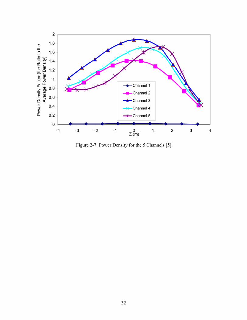
Figure 2-7: Power Density for the 5 Channels [5]........................................................................ 32
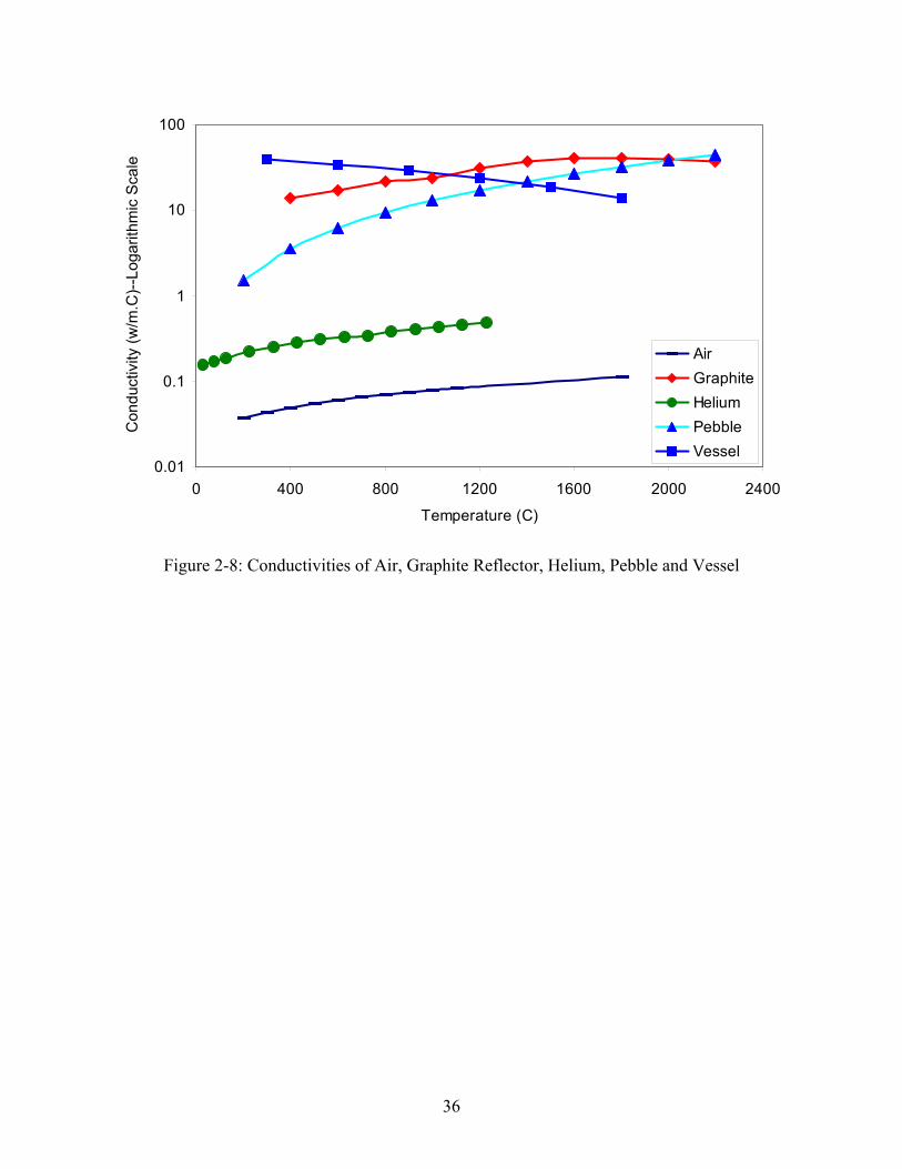
Figure 2-8: Conductivities of Air, Graphite Reflector, Helium, Pebble and Vessel .................... 36
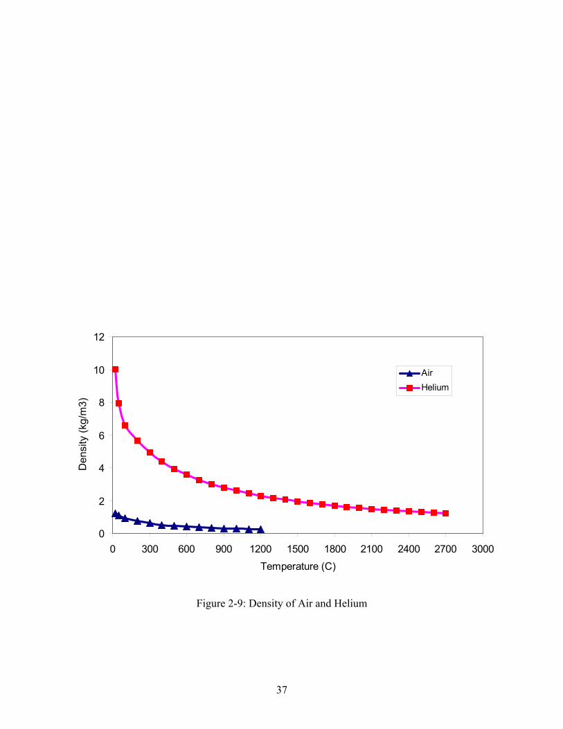
Figure 2-9: Density of Air and Helium......................................................................................... 37
Figure 2-10: Specific Heat of Air, Concrete,................................................................................ 38
Figure 2-11: Calculation Domain and Hat Transport Mechanisms Involved in Each Region [10]
............................................................................................................................................... 44
Figure 2-12: Hot-point Temperatures for LOCA.......................................................................... 46
Figure 2-13: The Temperature Profile on the 73rd Day in LOCA Analysis ................................. 47
Figure 2-14: Hot-point Temperature Sensitivity to Emissivities of Vessel and Concrete Wall in
the LOCA Analysis............................................................................................................... 48
Figure 2-15: Hot-point Temperature Sensitivity to the Conductivity of Soil and Concrete Wall in
the LOCA Analysis............................................................................................................... 51
Figure 2-16: Trends of Maximum Temperature for 0, 2,4,6 m/s of Air Velocity in the Air Gap
Region ................................................................................................................................... 53
Figure 3-1: Air Flow in Air Ingress Accident [1] ......................................................................... 59
Figure 3-2: Stage 1: Depressurization [12]................................................................................... 60
Figure 3-3: Stage 2: Molecular Diffusion [12] ............................................................................. 60
Figure 3-4: Stage 3: Natural Circulation [12] ............................................................................... 61
Figure 3-5: Schematic Diagram of Air Ingress Model ................................................................. 63
Figure 3-6: Procedures for Theoretical Study.............................................................................. 67
Figure 3-7: The Air Inlet Velocity vs. Pebble Bed's Average Temperature................................. 74
Figure 3-8: Air Inlet Velocity ...................................................................................................... 75
8
Figure 3-9: The Peak Temperature in the Core for Air Ingress Accident .................................... 76
Figure 3-10 Oxygen Mole Fraction in the Bottom Reflector ...................................................... 77
Figure 3-11: Experimental Apparatus for Isothermal and Non-Isothermal Experiments [13]..... 80
Figure 3-12: FLUENT Model for Isothermal and Non-Isohermal Experiments.......................... 81
Figure 3-13: The Structured Meshes for Isothermal and Non-Isothermal Experiments .............. 84
Figure 3-14: Mole Fraction of N2 Benchmarking of the Isothermal JAERI Experiment............. 85
Figure 3-15: N2 Mole Fraction Contour (t=0.25min) ................................................................... 85
Figure 3-16: N2 Mole Fraction Contour (t= 60 min) .................................................................... 86
Figure 3-17: N2 Mole Fraction Contour (t= 180 min) .................................................................. 86
Figure 3-18: The Constant Temperature Boundary Condition .................................................... 89
Figure 3-19: Comparison of mole fraction change of nitrogen between the gas sampling positions
H-1 and C-1 in the Non-Isothermal experiment ................................................................... 89
Figure 3-20: Comparison of mole fraction change of nitrogen between the gas sampling positions
H-2 and C-2 in the Non-Isothermal experiment ................................................................... 90
Figure 3-21: Comparison of mole fraction change of nitrogen between the gas sampling positions
H-4 and C-4 in the Non-Isothermal experiment ................................................................... 90
Figure 3-22: The Inlet and Outlet Velocity................................................................................... 91
Figure 3-23: Nitrogen Contour ( t = 0 min) .................................................................................. 92
Figure 3-24: Nitrogen Contour (t=1.6 min) .................................................................................. 93
Figure 3-25: Nitrogen Contour (t=75.5 min) ................................................................................ 93
Figure 3-26: Nitrogen Contour (t=123.3 min) .............................................................................. 94
Figure 3-27 Nitrogen Contour (t=220.43 min) ............................................................................ 94
Figure 3-28: Nitrogen Contour (t=222.55) ................................................................................... 95
Figure 3-29: Nitrogen Contour (t=223.03 min) ............................................................................ 95
Figure 3-30: Nitrogen Contour (t=223.20 min) ............................................................................ 96
Figure 3-31: Nitrogen Contour (t=223.28 min) ........................................................................... 96
Figure 3-32: Nitrogen Contour (t=224.00 min) ............................................................................ 97
Figure 3-33: Experimental Apparatus for Multi-component Experiment [13]............................. 99
Figure 3-34: FLUENT Model For Multi-component Experiment.............................................. 100
Figure 3-35: Distribution of the Measured Wall Temperature in the Whole Tube [13]............. 103
Figure 3-36: Distribution of the Wall Temperature in the Whole Tube Defined by UDF ......... 103
9
Figure 3-37: The Temperature Profile for the Multi-component Experiment............................ 104
Figure 3-38: Mole Fraction at point-1 ........................................................................................ 112
Figure 3-39: Mole fraction at point-3 ......................................................................................... 112
Figure 3-40: Mole Fraction at point-4 ........................................................................................ 113
Figure 3-41: Graphite Consumption Rate (FLUENT6.0 calculation) ........................................ 113
Figure 3-42: NACOK Experimental Apparatus [14].................................................................. 116
Figure 3-43: The Profile of the NACOK Experimental Apparatus [14] .................................... 117
Figure 3-44: The Profile of the NACOK Natural ....................................................................... 118
Figure 3-45: The Configuration of Pebble Bed .......................................................................... 120
Figure 3-46: Cell Configuration of the Pebble Bed.................................................................... 121
Figure 3-47: The Side View of the Pebble Geometry................................................................. 121
Figure 3-48: The Meshes Generated for the Top Structure ........................................................ 122
Figure 3-49: The Meshes Generated for the Bottom Structures ................................................. 122
Figure 3-50: Conductivity of the Pebbles ................................................................................... 127
Figure 3-51: The Specific Heat of the Pebbles ........................................................................... 127
Figure 3-52: The density of Air .................................................................................................. 128
Figure 3-53: The Specific Heat of Air ........................................................................................ 128
Figure 3-54: The Conductivity of Air......................................................................................... 129
Figure 3-55: The Viscosity of Air............................................................................................... 129
Figure 3-56: The Comparison between Experiments and Calculations...................................... 130
Figure 3-57: The Overall Geometry of a PBMR ........................................................................ 131
Figure 3-58: The Bottom Reflector of a PBMR ......................................................................... 132
Figure 3-59: The 30-degree Model for a PBMR ........................................................................ 132
Figure 3-60: The Test Model to the Future Detailed Study........................................................ 133
10
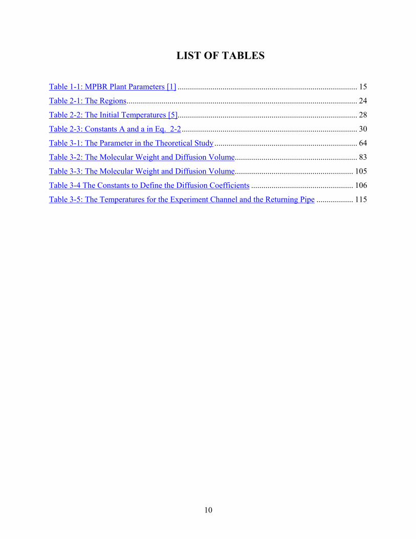
LIST OF TABLES
Table 1-1: MPBR Plant Parameters [1] ........................................................................................ 15
Table 2-1: The Regions................................................................................................................. 24
Table 2-2: The Initial Temperatures [5]........................................................................................ 28
Table 2-3: Constants A and a in Eq. 2-2...................................................................................... 30
Table 3-1: The Parameter in the Theoretical Study...................................................................... 64
Table 3-2: The Molecular Weight and Diffusion Volume............................................................ 83
Table 3-3: The Molecular Weight and Diffusion Volume.......................................................... 105
Table 3-4 The Constants to Define the Diffusion Coefficients .................................................. 106
Table 3-5: The Temperatures for the Experiment Channel and the Returning Pipe .................. 115
11
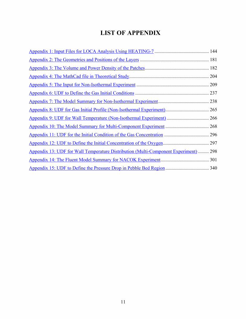
LIST OF APPENDIX
Appendix 1: Input Files for LOCA Analysis Using HEATING-7 ............................................. 144
Appendix 2: The Geometries and Positions of the Layers ......................................................... 181
Appendix 3: The Volume and Power Density of the Patches..................................................... 182
Appendix 4: The MathCad file in Theoretical Study.................................................................. 204
Appendix 5: The Input for Non-Isothermal Experiment ............................................................ 209
Appendix 6: UDF to Define the Gas Initial Conditions ............................................................. 237
Appendix 7: The Model Summary for Non-Isothermal Experiment.......................................... 238
Appendix 8: UDF for Gas Initial Profile (Non-Isothermal Experiment).................................... 265
Appendix 9: UDF for Wall Temperature (Non-Isothermal Experiment) ................................... 266
Appendix 10: The Model Summary for Multi-Component Experiment .................................... 268
Appendix 11: UDF for the Initial Condition of the Gas Concentration ..................................... 296
Appendix 12: UDF to Define the Initial Concentration of the Oxygen...................................... 297
Appendix 13: UDF for Wall Temperature Distribution (Multi-Component Experiment) ......... 298
Appendix 14: The Fluent Model Summary for NACOK Experiment........................................ 301
Appendix 15: UDF to Define the Pressure Drop in Pebble Bed Region .................................... 340
12
1. Introduction
1.1. Introduction
As a promising future energy option, HTGR technology is once again receiving increasing
interest in many countries. The main attractiveness of this technology is the modular design
concepts and passive safety. These features offer the promise of an economically competitive
electricity generation option, suitable for construction and operation in both industrialized and
developing countries. The high temperature capability and smaller unit size also provides the
prospect of non-electrical applications for high temperature process heat and for hydrogen
production, as well as low temperature energy supply for desalinization through cogeneration.
The Modular Pebble Bed Modular Reactor (MPBR) is a new type of high temperature helium
gas-cooled, graphite moderated nuclear reactor, which is recognized worldwide as an inherently
safe reactor type [1]. The pebble bed reactor is being developed at MIT and in South Africa. It is
a reactor where the inherent safety objective can be reasonably attained due to its low power
density and high heat capacity of the core. The most remarkable feature of this reactor is that it
has natural deterministic attributes that do not require active engineered safety systems to
prevent the core from melting in accident situations such as the complete loss of coolant.
While the overall safety of the pebble bed reactor is generally accepted, there are two specific
accidents that need to be analyzed and understood to validate these claims. The first is a loss of
coolant accident which is the standard type of accident assumed for light water reactors and the
second is more unique to high temperature graphite reactors – air ingress. The loss of coolant
accident in light water reactors requires active engineered safety systems to provide cooling
water quite quickly to prevent the core from melting. In high temperature pebble bed gas
reactors, the large amount of graphite which has a tremendous capability to store and transfer
heat and the low power density of the core, allows the reactor core to increase temperature very
slowly (80 hours) without active engineered systems and does not reach temperatures that will
melt the fuel.
13
The air ingress accident is important because of the potential for chemical reactions of air with
the graphite (carbon) in the reactor. Under certain circumstances, the graphite which makes up
much of the internals of the reactor, can aggressively react with the air contributing an additional
internal heat source and possibly burn. The details of the analysis are complex and only
generally understood. The purpose of this thesis is to develop a methodology using advanced
computational fluid dynamics methods to understand the complexities of the air ingress accident.
1.2. Description of MPBR [2]
The reactor consists of an annular core (3.5 meters in diameter) surrounded by graphite blocks.
There are about 300,000 graphite fuel pebbles in the core region, and each pebble consists of
~15,000 fuel micro-spheres. In the central region of the core, there are 110,000 graphite pebbles
consisting of no fuel. Each fuel micro-sphere is composed of a uranium dioxide pellet (enriched
to 8% U-235), enclosed in a three-layer (“TRISO”) coating consisting of a layer of silicon
carbide sandwiched by two layers of pyrolytic carbon. The “TRISO” fuel has exhibited good
fission product retention in German tests up to temperatures of about 1600 °C [3]. Both the core
and the graphite reflectors are installed in the pressure vessel. The normal operation pressure is
80 bars, and the safety limit temperature is 480 °C for the pressure vessel. An under-ground
reactor cavity is designed to reduce the possibility of radioactivity release and to transfer the
decay heat to the soil surrounding the cavity in the accident scenarios.
The temperature resistance of the fuel and the use of a single-phase-helium gas coolant enable
the reactor to operate at a coolant temperature of about 900 °C, considerably higher than the
operating temperature of LWRs. The higher temperature alone allows the reactor to achieve a
thermal efficiency of 45% (Table 1-1 shows the key PBMR plant parameters). The pebble bed
reactor can use either a direct or indirect gas turbine cycle (known as the Brayton cycle).
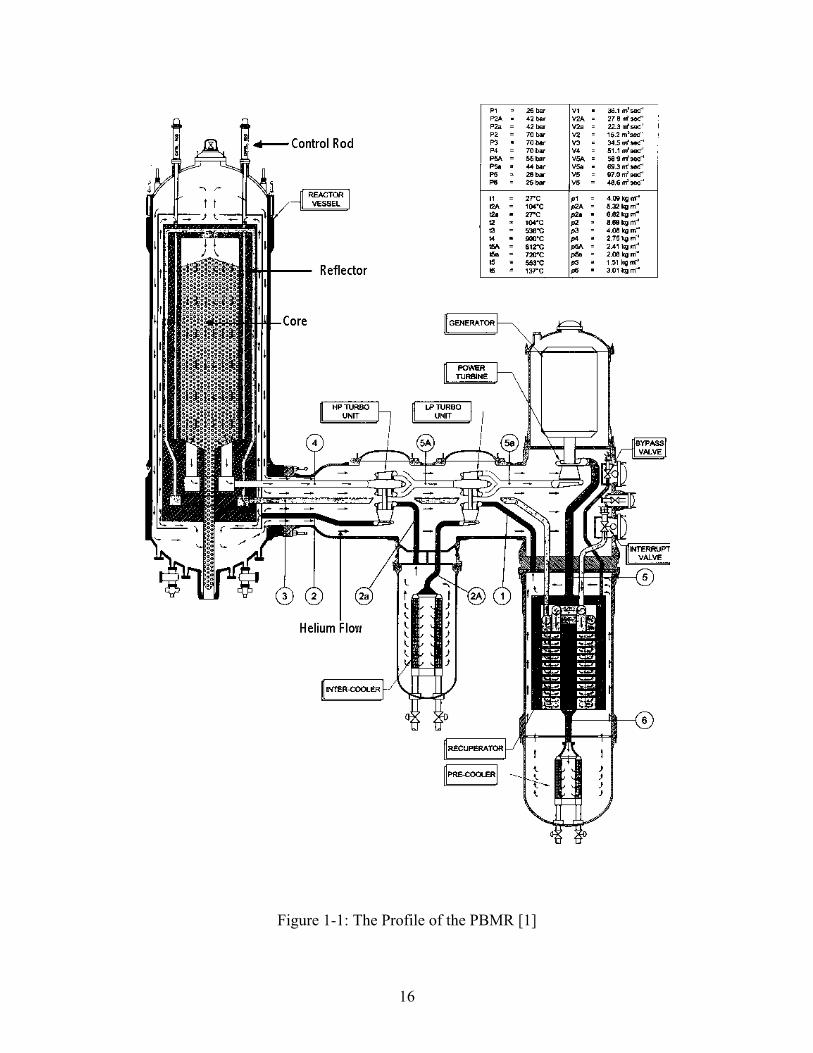
In the normal operation, fuel pebbles are continuously loaded at the top of the core, flow
downward, and are discharged at the bottom (shown in Figure 1-1). Shutdowns would be
required only for maintenance purposes because the PBMR is fueled while operating. Because
the MPBR is continuously refueled, the excess reactivity can be kept low. Also, the design has a
14
more negative fuel temperature coefficient than LWRs, as the Doppler feedback is greater for the
less-thermal neutron spectrum associated with a graphite moderator. These features reduce the
risk of reactivity accidents for most scenarios.
A major component of the PBMR safety basis is a low power density (an order of magnitude
below that of an LWR) and large thermal capacity (as a result of the large mass of graphite in the
core), together with the high-temperature resistance of the fuel. The maximum power rating of
each module (265 MWth) and the high surface-to-volume ratio of the core were chosen so that in
the event of a loss of coolant from the primary system, adequate cooling would be provided
without the need for forced convection. In the event of a total loss of primary coolant and no
operator intervention, the core heat-up rate would be slow and the maximum fuel temperature
would not exceed the target value (not safety limit) 1600 °C. Thus, the design does not include
conventional emergency core cooling systems, which are required for LWRs to provide
emergency water sources in the event of a loss-of-coolant accident.
Due to the high safety of MPBR, there are significant opportunities to reduce some of the costly
and, for the MPBR, unnecessary requirements that apply to the current generation of U.S.
nuclear plants. These proposals include (1) use of a confinement building instead of a robust
containment capable of preventing a large release of radioactive materials in the event of severe
core damage; (2) a reduction of the size of the emergency planning zone (EPZ) from 16
kilometers to 400 meters; (3) a reduction in the number of staff; and (4) a reduction in the
number of systems that are required for the safety of light water reactors.
15
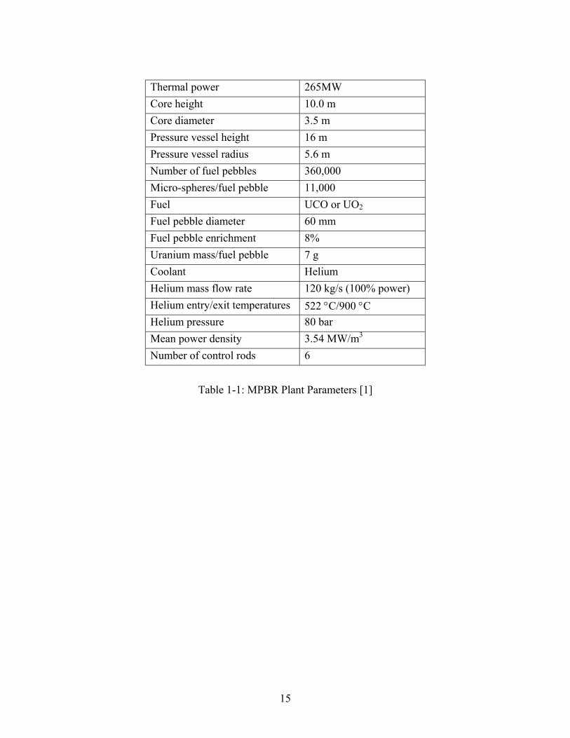
Thermal power 265MWCore height 10.0 mCore diameter 3.5 mPressure vessel height 16 mPressure vessel radius 5.6 mNumber of fuel pebbles 360,000Micro-spheres/fuel pebble 11,000Fuel UCO or UO2
Fuel pebble diameter 60 mmFuel pebble enrichment 8%Uranium mass/fuel pebble 7 gCoolant HeliumHelium mass flow rate 120 kg/s (100% power)Helium entry/exit temperatures 522 °C/900 °CHelium pressure 80 barMean power density 3.54 MW/m3
Number of control rods 6
Table 1-1: MPBR Plant Parameters [1]
16
Figure 1-1: The Profile of the PBMR [1]
17
1.3. Contributions of This Thesis
Unlike LWRs, the PBMR does not have the benefit of thousands of reactor-years' worth of
operating experience. In addition, the reported graphite burning during the Chernobyl accident
has raised public concerns about the behavior of other graphite moderated reactor types under
severe accident conditions, especially when air enters the primary circuit after a failure of the
primary system boundary. The consequences of an extensive graphite fire could be severe,
undermining the argument that a conventional containment is not needed. Radiological releases
from the Chernobyl accident were prolonged as a result of the fires which some allege was due
to the burning of graphite, which continued long after other fires were extinguished. Even though
the temperature of a graphite fire might not be high enough to severely damage the fuel micro-
spheres, the burning graphite itself would be radioactive as a result of neutron activation of
impurities and contamination with "tramp" uranium released from defective micro-spheres [3].
Although there is a difference of opinion as to whether the graphite actually burned at
Chernobyl, the air ingress accident needs to be understood which is the main purpose of this
thesis.
This thesis is divided into two parts, Part 1 deals with the Loss Of Coolant Accident (LOCA). A
detailed model is developed using HEATING-7 [4] to study the consequences of the accident,
especially the characteristics of the peak temperatures for the regions we most concerned. All the
key components that may significantly influence the heat transfer are modeled, and for the
unknown factors, conservative assumptions are made. This study will confirm the previous
findings of no core melting and identify significant needs to address the temperature limits of the
reactor vessel and reactor cavity. This analysis will also provide the initiating event conditions
for the air ingress accident.
In Part 2, the air ingress accident is studied in a step-by-step method. The goal of this work is to
understand the phenomenon of air ingress in a graphite core and develop a methodology using
computational fluid dynamics tools to more accurately model the air ingress for both pebble and
prismatic cores. There are many complicated processes involved in the air ingress accident:
18
diffusion, natural convection, dynamic and multiple chemical reactions in a complex geometry.
To address the complexities of the analysis a simplified theoretical study was performed to gain
an appreciation of the processes at work. This was followed by a CFD benchmarking program
based on experimental work performed by JAERI (Japanese Atomic Energy Research Institute)
in which the basic phenomenon of diffusion, natural circulation and chemical reactions are
separately tested to understand main mechanisms involved in the air ingress accident. This work
is applicable to prismatic reactors. To benchmark the pebble bed reactors, natural circulation
experiments performed by Forschungszentrum Julich GmbH were simulated using the CFD
code, FLUENT6.1 to develop a CFD method for the analysis of the air ingress accidents in the
pebble bed plants.
19
2. LOCA Analysis
2.1. Introduction
The inherent properties of the Modular Pebble Bed Reactor (MPBR) facilitate the design with
high degree of passive safe performance compared with other type of reactors. This analysis
examines the performance of the pebble bed reactor in response to a complete Loss of Coolant
Accident (LOCA) without the any active engineered features.
The loss-of-coolant accident is one of the most severe accidents for an MPBR. The challenge in
a LOCA is to remove the heat released by radioactive decay of fission products without core
damage by passive means only. This objective of this reactor concept is such that it should be
designed in such a way that the temperature limits will not be exceeded in such an accident, even
if no active heat removal measures are taken. While this might not be completely possible, this
analysis will identify the critical components that need to be addressed to assure that temperature
limits are not exceeded.
The purpose of the analysis presented below is to determine the peak temperatures for the core,
pressure vessel and concrete wall after a LOCA with depressurization which proceeds with no
means of core and reactor cavity cooling except for conductive and radiation heat transfer to the
soil surrounding the reactor cavity and natural convection from the enclosed top of the reactor
cavity to the air.
Once these peak temperatures are calculated, mitigating measures would need to be identified to
avoid exceeding temperature limits. This study assumes a reactor shutdown with a complete
depressurization as if caused by a double-ended guillotine break of the connecting vessel and
pipes. This is judged to be a more severe accident than a pressurized loss of coolant accident
(loss of flow).
20
The Modular Pebble Bed Reactor will be modeled for the detailed study. Once the baseline
calculation is concluded, a detailed sensitivity study will be conducted to identify critical
parameters or conditions that can enhance the passive heat removal processes for future designs.
2.2. Physical Phenomena
This analysis will model an equivalent double-ended guillotine break with an instantaneous
depressurization after operation for full power for an equilibrium core. The reactor is assumed to
be shutdown with the insertion of the shutdown rods. Within a very short period (about several
seconds), the pressure will be balanced between the reactor pressure vessel and the reactor cavity
as a result of the rapid blow-down. No active cooling system is assumed to remove decay heat
from the reactor. The decay heat generated in the reactor is transferred from the core through the
reactor vessel by conduction; from the reactor to the concrete reactor cavity by radiative heat
transfer; from the reactor cavity to the surrounding soil, which is the ultimate heat sink, by
conduction. Natural convection to the air from the top of the reactor cavity is also assumed.
The HEATING7 [4] code will be used as the code to calculate the heat transfer from the fuel
region through the reflector, the reactor vessel and through the reactor cavity to the earth as a
final heat sink. The initial power distribution for the modular pebble bed reactor will be obtained
from the VSOP code, which is the basic core neutronics code, used in pebble bed analysis[5].
2.3. Model Description
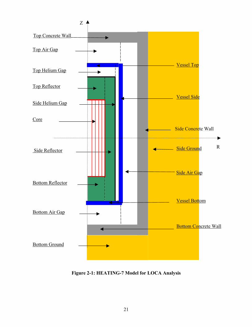
A three-dimensional model of the MPBR was developed for input to the HEATING-7 code. The
model divides the components involved into 21 regions, as shown in Figure 2-1, which are
composed of seven different materials: pebbles, graphite, helium, 2-1/4 Cr-Mo steel, air,
concrete, and soil. The core void is filled with stagnant helium. In some cases when the
properties for these materials could not be fully determined, conservative values were chosen as
a basis, and sensitivity analyses were performed on these undetermined parameters.
21
Bottom Air Gap
Figure 2-1: HEATING-7 Model for LOCA Analy
Bottom Ground
Top Reflector
Bottom Reflector
Side Reflector
Vessel Top
Side Ground
Top Concrete Wall
Top Air Gap
Core
R
Side Air Gap
Side Helium Gap
Bottom Concrete Wall
Vessel Bottom
Side Concrete Wall
Top Helium Gap
Z
Vessel Side
sis
22
2.3.1. HEATING-7 Description [4]
HEATING-7 is a general-purpose conduction heat transfer program written in Fortran 77. The
name HEATING is an acronym for Heat Engineering and Transfer In Nine Geometries (although
with modifications there are now 12 geometries). HEATING-7 can solve steady state and/or
transient heat conduction problems in one-, two-, or three-dimensional Cartesian, cylindrical, or
spherical coordinates. A model may include multiple materials, and the thermal conductivity,
density, and specific heat of each material may be both time- and temperature-dependent. The
thermal conductivity may also be anistotropic. Materials may undergo change of phase. Thermal
properties of materials may be input or may be extracted from a material properties library. Heat-
generation rates may be dependent on time, temperature, and position, and boundary
temperatures may be time- and position-dependent. The boundary conditions, which may be
surface-to-surface or surface-to-environment, may be specified temperatures or any combination
of prescribed heat flux, forced convection, natural convection, and radiation. General gray-body
radiation problems may be modeled with user-defined factors for radiant exchange. The mesh
spacing may be a variable along each axis. The code uses free-form-reading subroutines to
interpret the input data file, which is subdivided into data blocks identified by keywords.
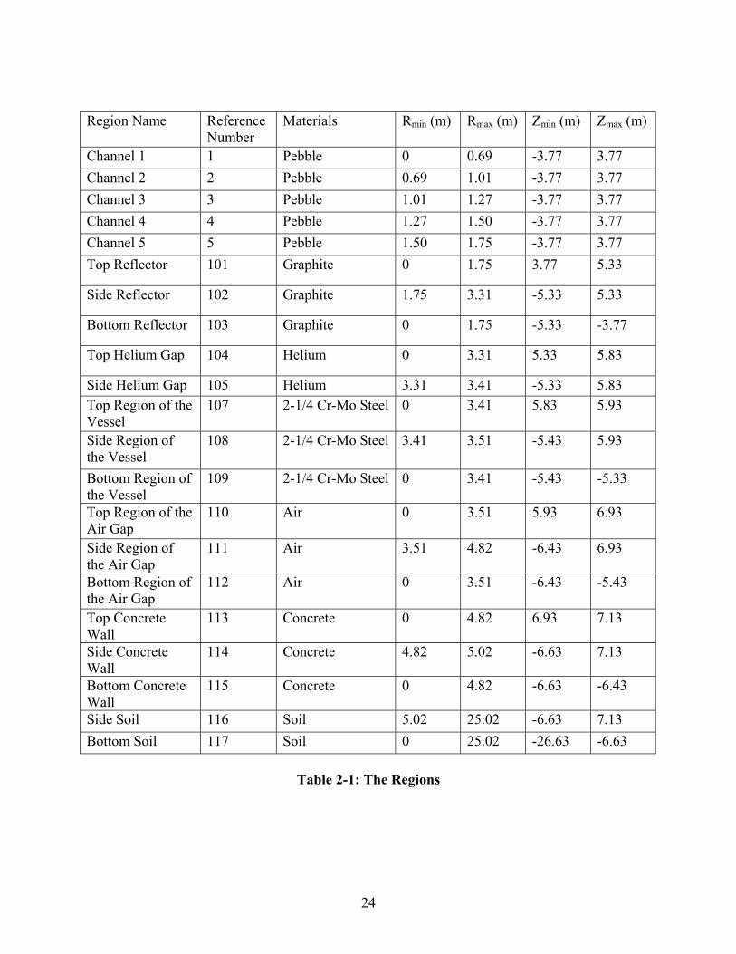
2.3.2. Regions and Mesh
In the 3-Dimensional model, a cylindrical coordinate is adopted and the complicated system is
divided into many regions mainly based on their thermal properties. For each edge in the inner
regions, all the edge lengths are 0.1 meter, and the total number of nodes in the model is 58,106
according this mesh schedule (For mesh details, see Appendix 1). Table 2-1 indicates the regions
involved in this model and their other properties. In this table, the reference numbers are used to
represent the regions. The center point of the core is selected as the origin of the cylindrical
coordinate system.
The core region is divided into 5 channels, and each channel consists of several layers based on
the fuel properties. There are 57 layers in the 5 channels: 9 layers in channel 1, 10 layers in

23
Channel 2, 11 layers in Channel 3, 12 layers in Channel 4 and 15 layers in Channel 5 (Shown in
Figure 2-2) [5]. (For the detailed description on the layers, see Appendix 2.) Each layer consists
of 11 patch, the reference number, power density and volume are shown in Appendix 3.
24
Region Name ReferenceNumber
Materials Rmin (m) Rmax (m) Zmin (m) Zmax (m)
Channel 1 1 Pebble 0 0.69 -3.77 3.77Channel 2 2 Pebble 0.69 1.01 -3.77 3.77Channel 3 3 Pebble 1.01 1.27 -3.77 3.77Channel 4 4 Pebble 1.27 1.50 -3.77 3.77Channel 5 5 Pebble 1.50 1.75 -3.77 3.77Top Reflector 101 Graphite 0 1.75 3.77 5.33
Side Reflector 102 Graphite 1.75 3.31 -5.33 5.33
Bottom Reflector 103 Graphite 0 1.75 -5.33 -3.77
Top Helium Gap 104 Helium 0 3.31 5.33 5.83
Side Helium Gap 105 Helium 3.31 3.41 -5.33 5.83Top Region of theVessel
107 2-1/4 Cr-Mo Steel 0 3.41 5.83 5.93
Side Region ofthe Vessel
108 2-1/4 Cr-Mo Steel 3.41 3.51 -5.43 5.93
Bottom Region ofthe Vessel
109 2-1/4 Cr-Mo Steel 0 3.41 -5.43 -5.33
Top Region of theAir Gap
110 Air 0 3.51 5.93 6.93
Side Region ofthe Air Gap
111 Air 3.51 4.82 -6.43 6.93
Bottom Region ofthe Air Gap
112 Air 0 3.51 -6.43 -5.43
Top ConcreteWall
113 Concrete 0 4.82 6.93 7.13
Side ConcreteWall
114 Concrete 4.82 5.02 -6.63 7.13
Bottom ConcreteWall
115 Concrete 0 4.82 -6.63 -6.43
Side Soil 116 Soil 5.02 25.02 -6.63 7.13Bottom Soil 117 Soil 0 25.02 -26.63 -6.63
Table 2-1: The Regions
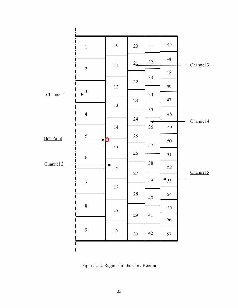
25
Figure 2-2: Regions in the Core Region
Channel 5
1
12
6
11
5
4
3
2
20 31 43
322144
3345
3513
14
23
24
15
25
10
36
37
26
22
50
34
49
48
47
46
54
7
16 52
51
38
8
9
18
19
29
1728
40
533927
30 5742
5641
55
Channel 1
Channel 2
Channel 3
Channel 4
Hot-Point

26
2.3.3. Assumptions
Although all the soil surrounding the cavity is the ultimate heat sink, the soil outer dimension of
the models is limited to 26 m. This assumption is made since heat transfer in soil is so slow that
only the soil surrounding the cavity is involved in the heat transfer over a long period of time.
The temperature distribution calculation confirmed this estimation and justified limiting the outer
radius. Heat removal by natural circulation is not considered since HEATING 7 cannot handle
convection processes. This makes the analysis more conservative. For this phase of the work,
chemical reactions are ignored leaving decay heat as the only source of heat addition to the
system. Components are assumed to maintain their geometric configuration. The core barrel
region, which is made of steel with high thermal conductivity relative to the other materials, is
neglected because of its low thermal resistance. In addition, the complicated geometry in the
bottom of the core is simplified: with the volumes unchanged, the original geometry of each
layer in the core bottom is modified to a regular one similar to the layers in the central region of
the core.
2.3.4. Initial Conditions and Boundary conditions
Initial equilibrium cycle core conditions at the time of reactor depressurization and shutdown
were obtained from calculations performed using the VSOP code by Lebenhaft [5]. The core
modeled was the ESKOM pebble-bed reactor being proposed in South Africa, which is being
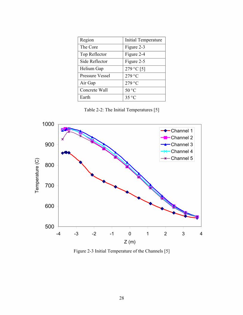
used by MIT as the reference core design. Table 2-2 shows the initial conditions, where the
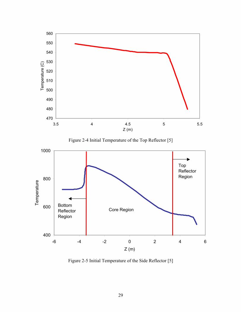
temperature is spatially dependent, the figures that display them are identified in the table. In
Figure 2-3, the five curves show the temperature distribution from the bottom (-3.77 meter) to
the top (+3.77 meters). The temperature distribution in the reflectors only depends the height of
the reflectors. In Figure 2-4 and Figure 2-5, lower Z refer to lower part of the reflectors. For the
side reflector, its peak temperature locates in the lower part since the helium flow from the top to
the bottom in the normal operation. The air in the reactor cavity region is assumed to be stagnant
and heat transfer occurs only by conduction and radioactive heat transfer as previously described.
The initial temperature of the pressure vessel is assumed to be the temperature of the helium gap
27
since the conductivity of the pressure vessel is high. Very conservatively, the initial temperature
of the air in the cavity is equal to the pressure vessel temperature. The initial temperature of the
concrete wall and the soil were assumed to be 50 °C and 35 °C respectively. The boundary
temperatures are assumed to be the temperatures of the soil – 35 °C.
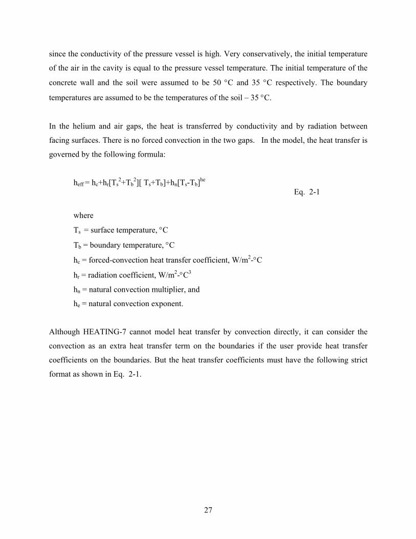
In the helium and air gaps, the heat is transferred by conductivity and by radiation between
facing surfaces. There is no forced convection in the two gaps. In the model, the heat transfer is
governed by the following formula:
heff = hc+hr[Ts2+Tb
2][ Ts+Tb]+hn[Ts-Tb]he Eq. 2-1
where
Ts = surface temperature, °C
Tb = boundary temperature, °C
hc = forced-convection heat transfer coefficient, W/m2-°C
hr = radiation coefficient, W/m2-°C3
hn = natural convection multiplier, and
he = natural convection exponent.
Although HEATING-7 cannot model heat transfer by convection directly, it can consider the
convection as an extra heat transfer term on the boundaries if the user provide heat transfer
coefficients on the boundaries. But the heat transfer coefficients must have the following strict
format as shown in Eq. 2-1.
28
Region Initial Temperature The Core Figure 2-3Top Reflector Figure 2-4Side Reflector Figure 2-5Helium Gap 279 °C [5]Pressure Vessel 279 °C Air Gap 279 °C Concrete Wall 50 °CEarth 35 °C
Table 2-2: The Initial Temperatures [5]
500
600
700
800
900
1000
-4 -3 -2 -1 0 1 2 3 4Z (m)
Tem
pera
ture
(C)
Channel 1Channel 2Channel 3Channel 4Channel 5
Figure 2-3 Initial Temperature of the Channels [5]
29
470
480
490
500
510
520
530
540
550
560
3.5 4 4.5 5 5.5Z (m)
Tem
pera
ture
(C)
Figure 2-4 Initial Temperature of the Top Reflector [5]
400
600
800
1000
-6 -4 -2 0 2 4 6Z (m)
Tem
pera
ture
Core RegionBottom Reflector Region
Top Reflector Region
Figure 2-5 Initial Temperature of the Side Reflector [5]
30
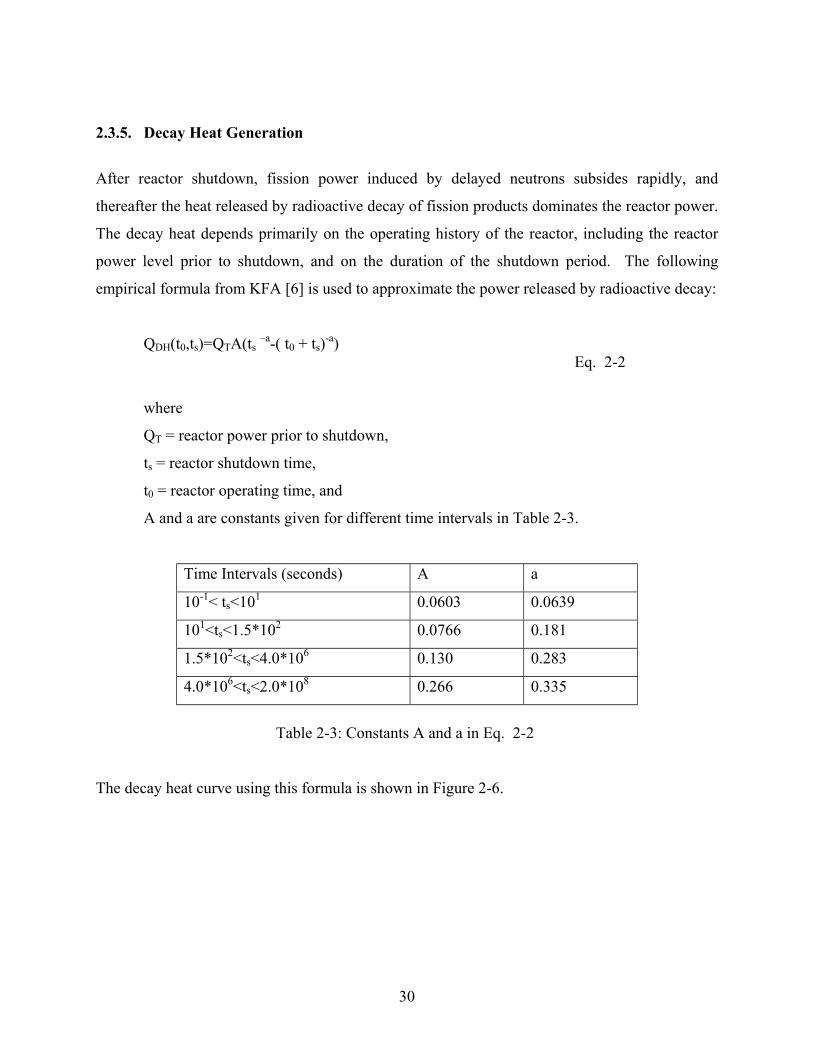
2.3.5. Decay Heat Generation
After reactor shutdown, fission power induced by delayed neutrons subsides rapidly, and
thereafter the heat released by radioactive decay of fission products dominates the reactor power.
The decay heat depends primarily on the operating history of the reactor, including the reactor
power level prior to shutdown, and on the duration of the shutdown period. The following
empirical formula from KFA [6] is used to approximate the power released by radioactive decay:
QDH(t0,ts)=QTA(ts –a-( t0 + ts)-a)Eq. 2-2
where
QT = reactor power prior to shutdown,
ts = reactor shutdown time,
t0 = reactor operating time, and
A and a are constants given for different time intervals in Table 2-3.
Time Intervals (seconds) A a
10-1< ts<101 0.0603 0.0639
101<ts<1.5*102 0.0766 0.181
1.5*102<ts<4.0*106 0.130 0.283
4.0*106<ts<2.0*108 0.266 0.335
Table 2-3: Constants A and a in Eq. 2-2
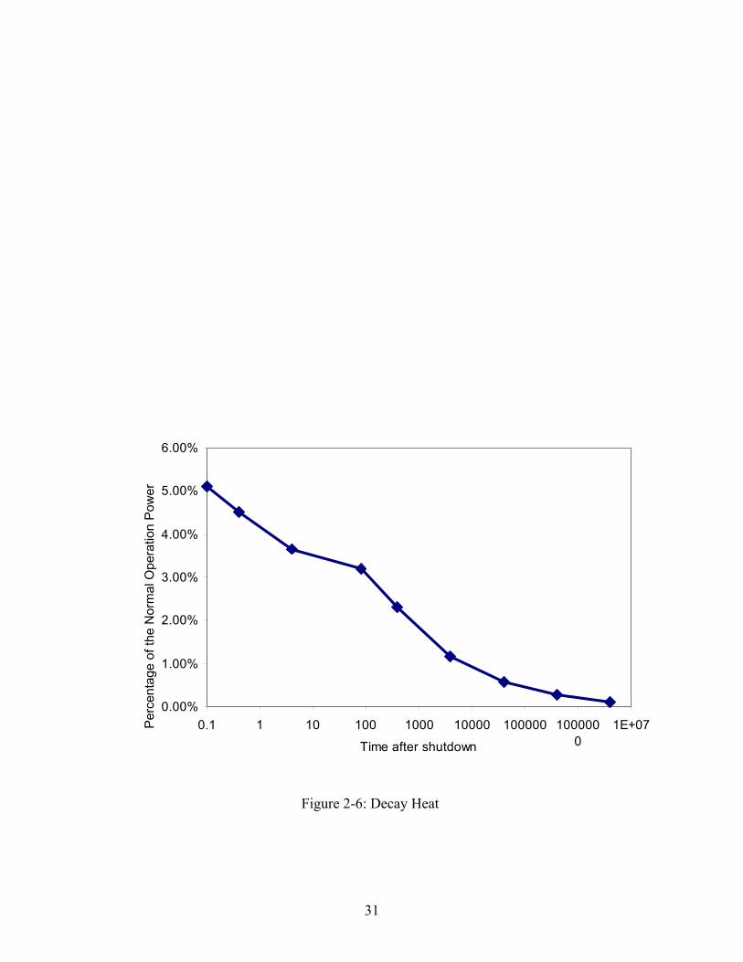
The decay heat curve using this formula is shown in Figure 2-6.
31
0.00%
1.00%
2.00%
3.00%
4.00%
5.00%
6.00%
0.1 1 10 100 1000 10000 100000 1000000
1E+07
Time after shutdown
Perc
enta
ge o
f the
Nor
mal
Ope
ratio
n Po
wer
Figure 2-6: Decay Heat
32
0
0.2
0.4
0.6
0.8
1
1.2
1.4
1.6
1.8
2
-4 -3 -2 -1 0 1 2 3 4Z (m)
Pow
er D
ensi
ty F
acto
r (th
e R
atio
to th
e Av
erag
e Po
wer
Den
sity
)
Channel 1
Channel 2
Channel 3
Channel 4
Channel 5
Figure 2-7: Power Density for the 5 Channels [5]
33
2.3.6. Material Properties
The Pebbles
Heat transfer in the core involves both thermal conduction through fuel elements and radiation
through the voids between pebbles. The inner reflector is made of graphite pebbles that have the
same geometry as the pure fuel pebbles. Here, we ignore the heat convection between helium
and fuel pebbles. The density of the pebble bed region is 729.5 kg/m3 [6]. General Electric
developed a correlation for the calculation of the pebble bed thermal conductivity which depends
only on core temperature and is given by [6] and shown in Figure 2-8:
K(T) = 1.1536*10-4(T-173.16)1.6622
Eq. 2-3
The specific capacity (ρijCpij) can be determined by the correlation given by [6]:
ρijCpij(Tij)=1.75(1-ε)[0.645+3.14((Tij-T0)/1000)-2.809((Tij-T0)/1000)2+0.959((Tij-T0)/1000)3]Eq. 2-4
Where
ε = Void fraction of the pebble bed,
T ij = Nodal temperature, K,
T 0 = 273.16K,
ρijCpij = nodal heat capacity density, J/K-CM3.
The void fraction of the pebble bed could be calculated using the following formula[23]:
ε = 0.78/[(D/d)2]+0.375Eq. 2-5
Where,
D: The diameter of the vessel,
34
d: The diameters of the pebbles.
For the PBMR, the diameter of the reactor vessel is 3.5 meters, and the diameter of the pebble is
0.06 meter. Thus, the average void fraction (porosity) is ~0.375.
The Graphite Reflectors [6]
The density of the side reflector is 1394.8 kg/m3. The conductivity of graphite depends on
temperature, and it is shown in the Figure 2-8. The Specific Heat of graphite is shown in Figure
2-10.
The Helium Gap
The density and conductivity of Helium depends on temperature, and it is given in theFigure 2-7
and Figure 2-8, respectively. Its’ Specific Heat is a constant-5193.0 J/kg.°C[6].
The Pressure Vessel - 2-1/4 Cr-Mo Steel
The density of the 2-1/4 Cr-Mo Steel used as the reactor material is assumed to be constant at
7833.35 kg/m3[6]. The thermal conductivity of the vessel as a function of temperature is
computed by the following formula[6]:
K2-1/4Cr-Mo(T)=49.341695-0.017228.T Eq. 2-6
Where
T, Vessel temperature in (K)
K2-1/4Cr-Mo, the thermal conductivity in (W/m-K)
The Specific Heat of the vessel as a function of temperature is computed by the following
formula [6] (shown in Figure 2-10):
35
Cp2-1/4Cr-Mo(T)=380.962+0.535104*T-6.10413*10-4*T2+3.02469*10-7*T3
Eq. 2-7The emissivity of the pressure vessel is a constant, 0.73[8].
The Air [7]
The density, thermal conductivity and specific heat of the air as a function of temperature are
shown in Figure 2-8, Figure 2-9 and Figure 2-10.
The Concrete Wall
Assume the thermal conductivity, density and specific heat of the concrete wall as a function of
temperatures are constant at 0.79 w/m.°C, 1930.0 kg/m3, 880.0 J/kg.°C, respectively[6]. The
emissivity of the concrete wall is a constant, 0.7[8].
The Soil
Assume the thermal conductivity, density and specific heat of the concrete wall as a function of
temperatures are constant at 0.83 w/m.°C, 1900.0 kg/m3, 1500 J/kg.°C, respectively[6].
36
0.01
0.1
1
10
100
0 400 800 1200 1600 2000 2400
Temperature (C)
Con
duct
ivity
(w/m
.C)--
Loga
rithm
ic S
cale
AirGraphiteHeliumPebbleVessel
Figure 2-8: Conductivities of Air, Graphite Reflector, Helium, Pebble and Vessel
37
0
2
4
6
8
10
12
0 300 600 900 1200 1500 1800 2100 2400 2700 3000Temperature (C)
Den
sity
(kg/
m3)
AirHelium
Figure 2-9: Density of Air and Helium

38
Figure 2-10: Specific Heat of Air, Concrete, Graphite Reflector, Pebbles and Pressure Vessel
0
1000
2000
3000
4000
5000
6000
0 500 1000 1500 2000 2500Temperature (C)
Spec
ific
Hea
t (J/
kg.C
)
AirConcreteGraphitePebbleVessel
39
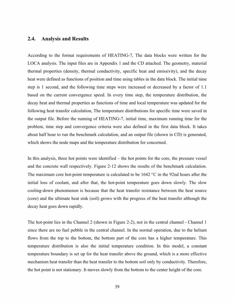
2.4. Analysis and Results
According to the format requirements of HEATING-7, The data blocks were written for the
LOCA analysis. The input files are in Appendix 1 and the CD attached. The geometry, material
thermal properties (density, thermal conductivity, specific heat and emissivity), and the decay
heat were defined as functions of position and time using tables in the data block. The initial time
step is 1 second, and the following time steps were increased or decreased by a factor of 1.1
based on the current convergence speed. In every time step, the temperature distribution, the
decay heat and thermal properties as functions of time and local temperature was updated for the
following heat transfer calculation, The temperature distributions for specific time were saved in
the output file. Before the running of HEATING-7, initial time, maximum running time for the
problem, time step and convergence criteria were also defined in the first data block. It takes
about half hour to run the benchmark calculation, and an output file (shown in CD) is generated,
which shows the node maps and the temperature distribution for concerned.
In this analysis, three hot points were identified – the hot points for the core, the pressure vessel
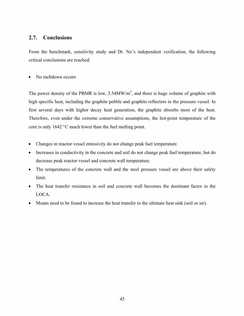
and the concrete wall respectively. Figure 2-12 shows the results of the benchmark calculation.
The maximum core hot-point temperature is calculated to be 1642 °C in the 92nd hours after the
initial loss of coolant, and after that, the hot-point temperature goes down slowly. The slow
cooling-down phenomenon is because that the heat transfer resistance between the heat source
(core) and the ultimate heat sink (soil) grows with the progress of the heat transfer although the
decay heat goes down rapidly.
The hot-point lies in the Channel 2 (shown in Figure 2-2), not in the central channel - Channel 1
since there are no fuel pebble in the central channel. In the normal operation, due to the helium
flows from the top to the bottom, the bottom part of the core has a higher temperature. This
temperature distribution is also the initial temperature condition. In this model, a constant
temperature boundary is set up for the heat transfer above the ground, which is a more effective
mechanism heat transfer than the heat transfer to the bottom soil only by conductivity. Therefore,
the hot point is not stationary. It moves slowly from the bottom to the center height of the core.
40
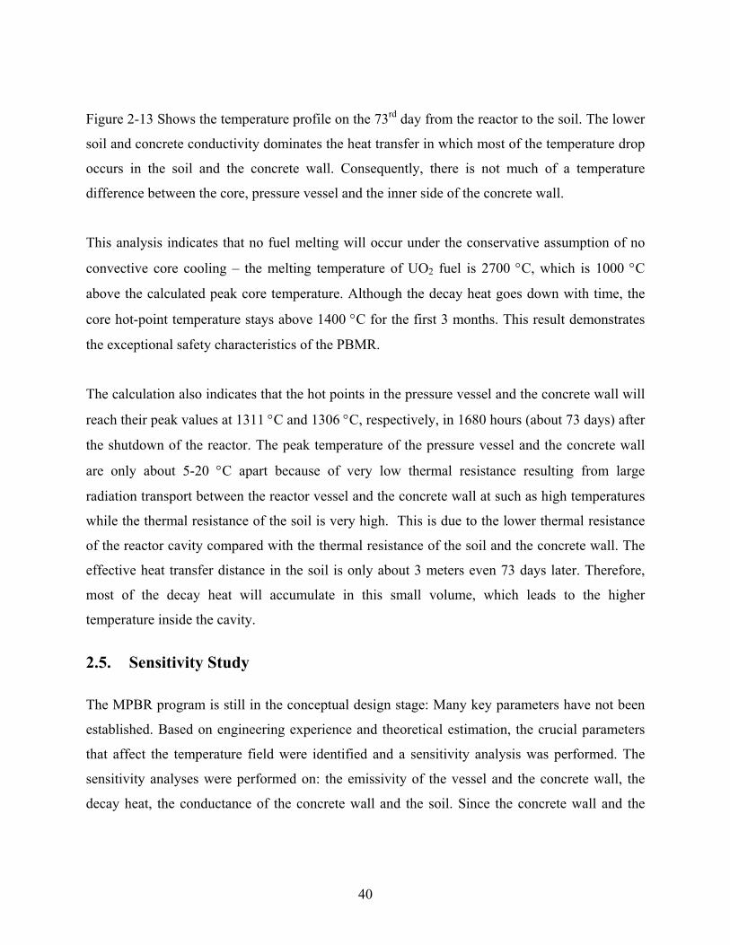
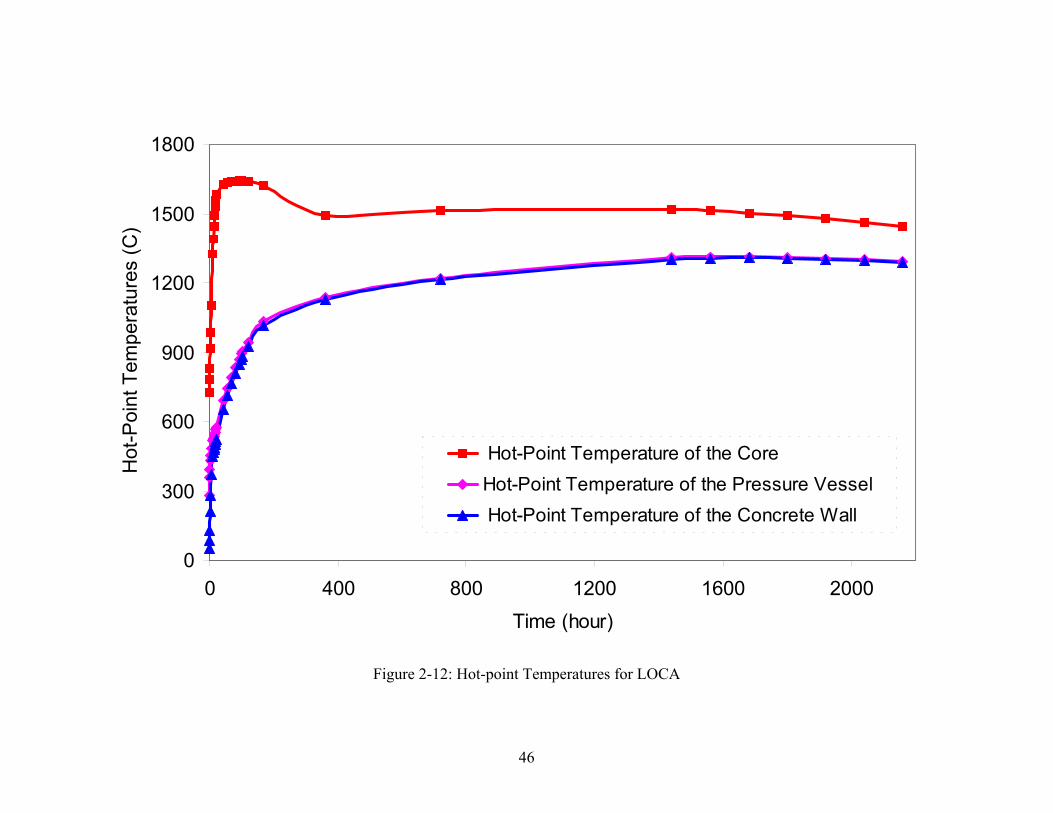
Figure 2-13 Shows the temperature profile on the 73rd day from the reactor to the soil. The lower
soil and concrete conductivity dominates the heat transfer in which most of the temperature drop
occurs in the soil and the concrete wall. Consequently, there is not much of a temperature
difference between the core, pressure vessel and the inner side of the concrete wall.
This analysis indicates that no fuel melting will occur under the conservative assumption of no
convective core cooling – the melting temperature of UO2 fuel is 2700 °C, which is 1000 °C
above the calculated peak core temperature. Although the decay heat goes down with time, the
core hot-point temperature stays above 1400 °C for the first 3 months. This result demonstrates
the exceptional safety characteristics of the PBMR.
The calculation also indicates that the hot points in the pressure vessel and the concrete wall will
reach their peak values at 1311 °C and 1306 °C, respectively, in 1680 hours (about 73 days) after
the shutdown of the reactor. The peak temperature of the pressure vessel and the concrete wall
are only about 5-20 °C apart because of very low thermal resistance resulting from large
radiation transport between the reactor vessel and the concrete wall at such as high temperatures
while the thermal resistance of the soil is very high. This is due to the lower thermal resistance
of the reactor cavity compared with the thermal resistance of the soil and the concrete wall. The
effective heat transfer distance in the soil is only about 3 meters even 73 days later. Therefore,
most of the decay heat will accumulate in this small volume, which leads to the higher
temperature inside the cavity.
2.5. Sensitivity Study
The MPBR program is still in the conceptual design stage: Many key parameters have not been
established. Based on engineering experience and theoretical estimation, the crucial parameters
that affect the temperature field were identified and a sensitivity analysis was performed. The
sensitivity analyses were performed on: the emissivity of the vessel and the concrete wall, the
decay heat, the conductance of the concrete wall and the soil. Since the concrete wall and the
41
reactor vessel have the about same hot-point temperature, the figures in the sensitivity study only
show the temperature curves for concrete wall.
2.5.1. Peak Temperature Sensitivities to the Emissivities of the Vessel and the Concrete
Wall
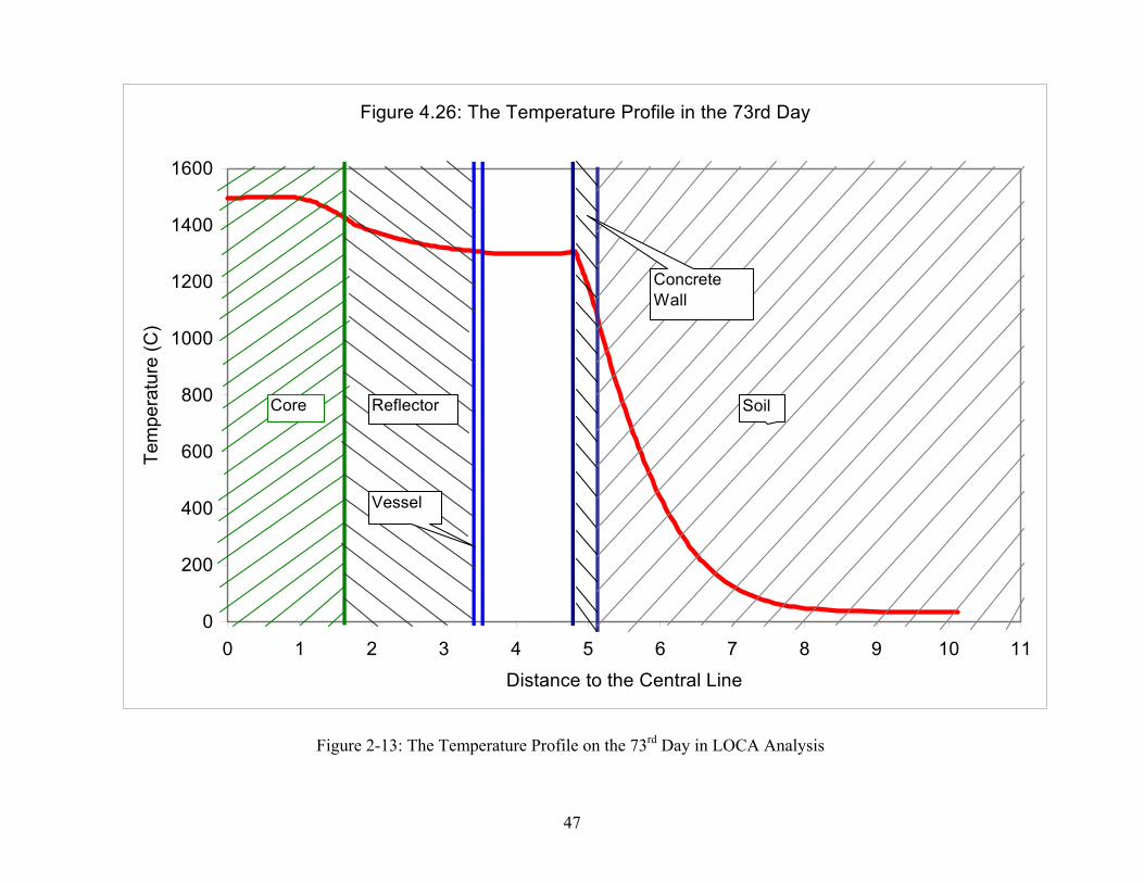
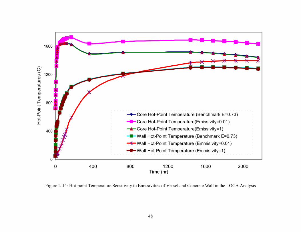
Reference [8] indicates that the emissivity of the reactor vessel is 0.73 and the average emissivity
of the concrete wall is 0.7. Therefore, in the emissivity sensitivity analysis, Two extreme
scenarios are studied: the concrete wall and reactor vessel with the lowest emissivity 0.01 and
both with the highest emissivity 1. The best estimate emissivity value used in the analysis is
0.73.
For the case with lowest emissivity, the hot-point temperature of the core is higher than the
benchmark, and always above 1600°C after the peak value in the first 3 months (Shown in
Figure 2-14). Moreover, due to the isolation function by the lower emissivities, most of the heat
will be deposited inside of the vessel at the beginning, so the concrete wall has a lower
temperature in the first 900 hrs. 900 hours later, the soil becomes the main heat sink instead of
the core region, and most of the temperature drop will be in the soil. Consequently, the concrete
will have a higher hot point peak temperature (about 1400°C) than the benchmark (1307°C) due
to the higher thermal resistance from the emissivities. But there is no obvious shift of the
temperature curve between the case with emissivity of 1.0 and the case with emissivity of
0.73(benchmark calculation). Thus, emissivity does not appear to be a critical factor in peak core
temperature.
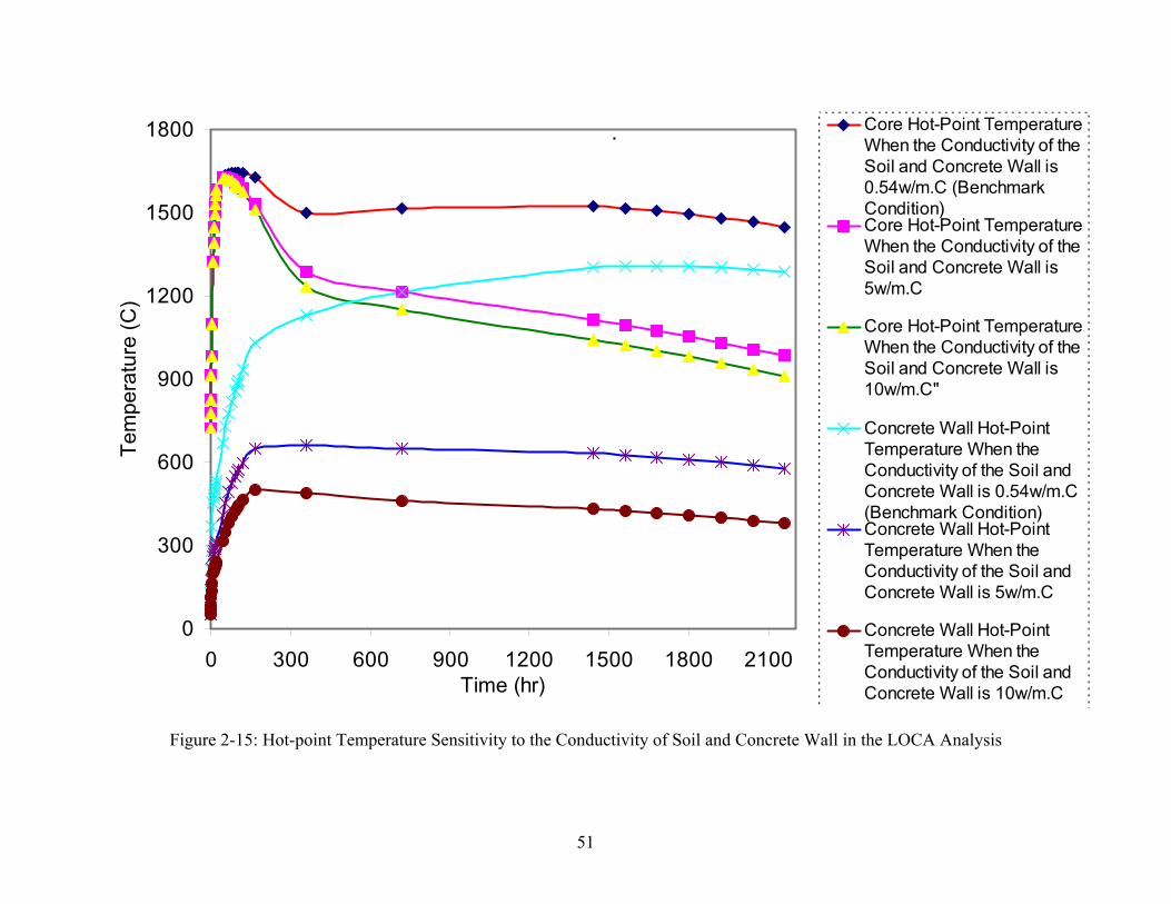
2.5.2. Peak Temperature Sensitivities to the Conductivity of the Soil and the Concrete
Wall
In the sensitivity analysis on the conductivity of soil and concrete wall, the conductivity of the
soil and concrete wall were adjusted at the same time. In Figure 2-15, we can see a surprising
result: even if the soil has the conductivity of the Mercury (the conductivity of mercury is
10.3w/m.°C at 200°C, and will increase for the higher temperature), there is almost no change of
42
the core peak temperature. Although the peak temperatures of concrete wall and pressure vessel
decrease dramatically, they are still at 535 °C, which is higher than their safety limitations. The
safety limitations for the vessel and concrete wall are 482 °C and 177 °C, respectively. Thus,
while the unproved conductivities of the soil and concrete wall will help reduce the peak
temperature of the concrete wall and pressure vessel, the peak core temperature is unaffected.
2.6. Independent Verification Using PBR_SIM
As an independent confirmatory check, calculations were performed by Hee Cheon No to
benchmark the HEATING-7 results [10]. Dr. Hee Cheon No independently developed the
PBR_SIM (Pebble Bed Reactor_SIMulation). Following is a brief description of his model [10]:
a. Nodal scheme in primary system:
• 12 axial divisions: 10 core nodes, 1 lower reflector, 1 upper reflector, top reactor
vessel and containment, bottom reactor vessel, containment, and soil.
• 20 radial divisions: 5 pebble and divisions, 1 outer reflector, 1 core barrel node, 1
reactor vessel, 1 air gap, 3 concrete and 8 soil divisions.
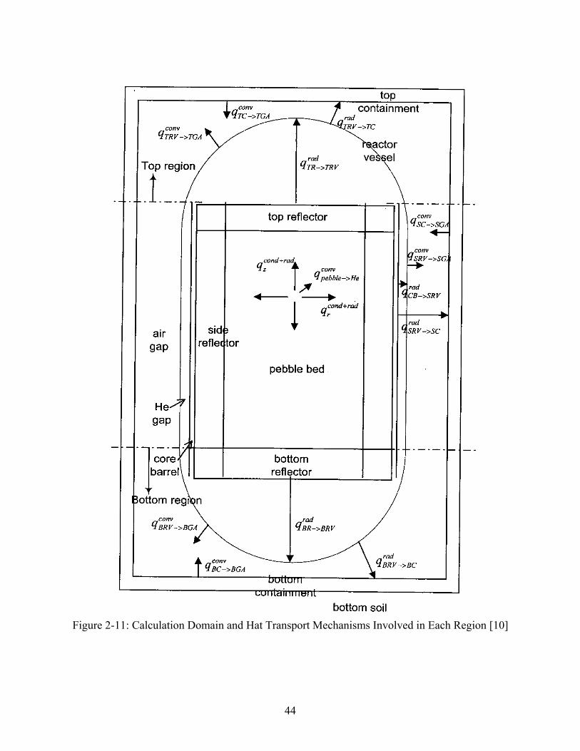
b. Heat transport scheme in primary system (Shown in Figure 2-11):
• Core nodes: radial and axial conduction + radiation, axial convection from the top to
the bottom
• Air gap region: axial convection from the bottom to the top, the wall convective heat
transfer by combination of both air natural convection and forced convection
• He gap regions between the core barrel and the inner surface of the reactor vessel, and
between the outer surface of the reflectors to the inner surface of the reactor vessel:
radial radiation transport between solid walls.
• Other solids: radial conduction heat transfer
• Easy adoption of realistic boundary condition with constant temperature on 25 m
from the center of the core or of constant temperature boundary conditions of the
43
concrete, the soil, and the reactor vessel provided by the active/passive concrete
cooling system and the He cooling system.
c. Main assumptions involved in models in primary system
• Constant temperatures of structures and air above the top containment
• Averaged temperatures in the top and bottom reactor vessel and containment
• No radial convective mixing in the gas region
d. Capability of the Code
• Core thermal-hydraulic dynamic analysis for system control
• Core thermal-hydraulic analysis in operational transients and depressurization
accident
• Analysis for passive or active concrete cooling system or decay heat residual cooling
system.
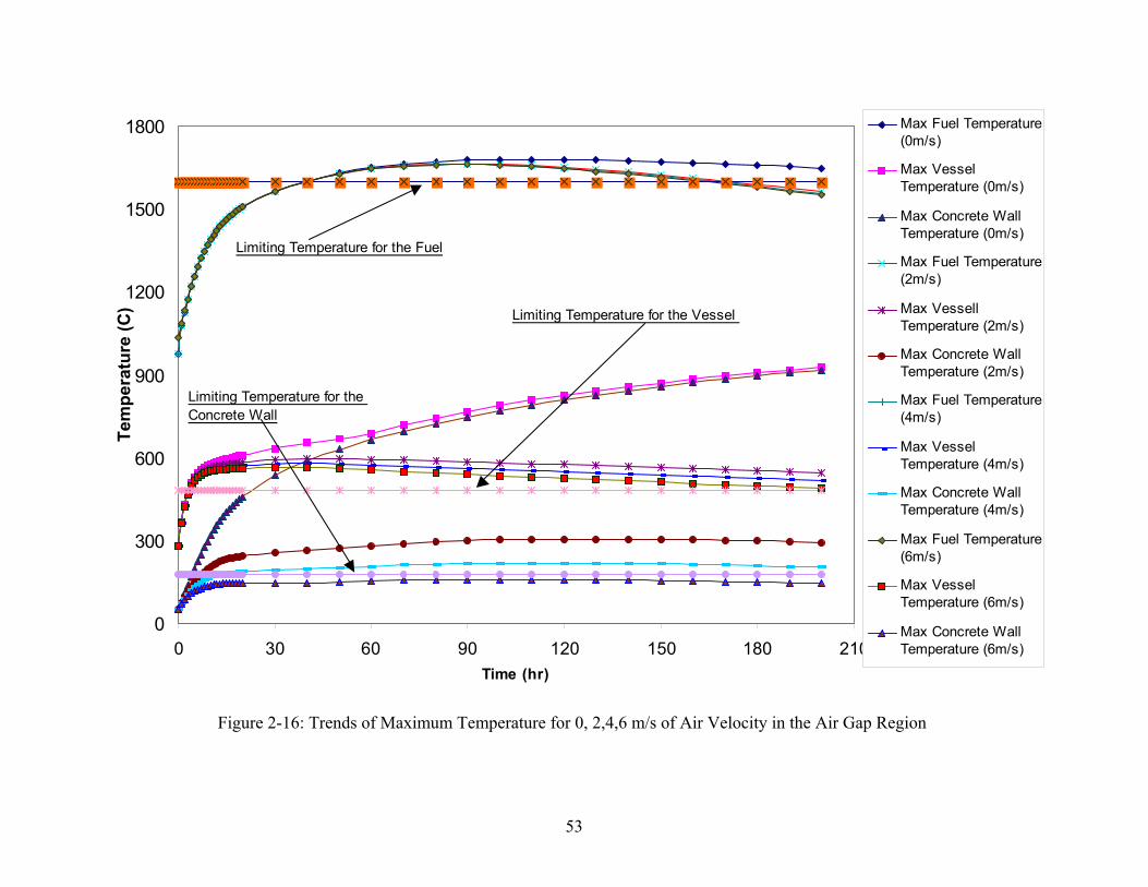
Dr. No's summary conclusions are shown on Figure 2-16. The benchmark case (0 m/s coolant
velocity) agrees well with HEATING-7 prediction assuming no convective cooling. His
calculation indicates that the fuel temperature reaches a maximum one of 1679 °C at 108 hours
(the fuel peak temperature is 1642 °C at 92 hours). In addition, PBR-SIM has the capability to
model convective cooling in the reactor cavity to determine the flow velocity necessary to keep
the hot-point temperatures below their safety limit PBR_SIM calculations indicate that with a
convective coolant flow in the reactor cavity of approximately 6 meters per second, the concrete
peak temperatures can be maintained within allowable limits, but the reactor vessel temperatures
are still above the allowable range. Moreover, there is no significant temperature drop of the core
hot-point temperature with the coolant velocities of 2m/s, 4m/s and 6m/s. This suggests that
some form of convection cooling is required to maintain the reactor vessel and reactor cavity
concrete within design limits.
44
Figure 2-11: Calculation Domain and Hat Transport Mechanisms Involved in Each Region [10]
45
2.7. Conclusions
From the benchmark, sensitivity study and Dr. No’s independent verification, the following
critical conclusions are reached:
• No meltdown occurs
The power density of the PBMR is low, 3.54MW/m3, and there is huge volume of graphite with
high specific heat, including the graphite pebble and graphite reflectors in the pressure vessel. In
first several days with higher decay heat generation, the graphite absorbs most of the heat.
Therefore, even under the extreme conservative assumptions, the hot-point temperature of the
core is only 1642 °C much lower than the fuel melting point.
• Changes in reactor vessel emissivity do not change peak fuel temperature.
• Increases in conductivity in the concrete and soil do not change peak fuel temperature, but do
decrease peak reactor vessel and concrete wall temperature.
• The temperatures of the concrete wall and the steel pressure vessel are above their safety
limit.
• The heat transfer resistance in soil and concrete wall becomes the dominant factor in the
LOCA.
• Means need to be found to increase the heat transfer to the ultimate heat sink (soil or air).
46
0
300
600
900
1200
1500
1800
0 400 800 1200 1600 2000Time (hour)
Hot
-Poi
nt T
empe
ratu
res
(C)
Hot-Point Temperature of the CoreHot-Point Temperature of the Pressure Vessel Hot-Point Temperature of the Concrete Wall
Figure 2-12: Hot-point Temperatures for LOCA
47
Figure 2-13: The Temperature Profile on the 73rd Day in LOCA Analysis
Figure 4.26: The Temperature Profile in the 73rd Day
0
200
400
600
800
1000
1200
1400
1600
0 1 2 3 4 5 6 7 8 9 10 11Distance to the Central Line
Tem
pera
ture
(C)
Vessel
Core Reflector Soil
ConcreteWall
48
0
400
800
1200
1600
0 400 800 1200 1600 2000Time (hr)
Hot
-Poi
nt T
empe
ratu
res
(C)
Core Hot-Point Temperature (Benchmark E=0.73)Core Hot-Point Temperature(Emissivity=0.01)Core Hot-Point Temperature(Emissivity=1)Wall Hot-Point Temperature (Benchmark E=0.73)Wall Hot-Point Temperature (Emmisivity=0.01)Wall Hot-Point Temperature (Emmisivity=1)
Figure 2-14: Hot-point Temperature Sensitivity to Emissivities of Vessel and Concrete Wall in the LOCA Analysis

49

50
51
.
0
300
600
900
1200
1500
1800
0 300 600 900 1200 1500 1800 2100Time (hr)
Tem
pera
ture
(C)
Core Hot-Point TemperatureWhen the Conductivity of theSoil and Concrete Wall is0.54w/m.C (BenchmarkCondition)Core Hot-Point TemperatureWhen the Conductivity of theSoil and Concrete Wall is5w/m.C
Core Hot-Point TemperatureWhen the Conductivity of theSoil and Concrete Wall is10w/m.C"
Concrete Wall Hot-PointTemperature When theConductivity of the Soil andConcrete Wall is 0.54w/m.C(Benchmark Condition)Concrete Wall Hot-PointTemperature When theConductivity of the Soil andConcrete Wall is 5w/m.C
Concrete Wall Hot-PointTemperature When theConductivity of the Soil andConcrete Wall is 10w/m.C
Figure 2-15: Hot-point Temperature Sensitivity to the Conductivity of Soil and Concrete Wall in the LOCA Analysis

52
53
0
300
600
900
1200
1500
1800
0 30 60 90 120 150 180 210Time (hr)
Tem
pera
ture
(C)
Max Fuel Temperature(0m/s)
Max VesselTemperature (0m/s)
Max Concrete WallTemperature (0m/s)
Max Fuel Temperature(2m/s)
Max VessellTemperature (2m/s)
Max Concrete WallTemperature (2m/s)
Max Fuel Temperature(4m/s)
Max VesselTemperature (4m/s)
Max Concrete WallTemperature (4m/s)
Max Fuel Temperature(6m/s)
Max VesselTemperature (6m/s)
Max Concrete WallTemperature (6m/s)
Limiting Temperature for the Fuel
Limiting Temperature for the Vessel
Limiting Temperature for the Concrete Wall
Figure 2-16: Trends of Maximum Temperature for 0, 2,4,6 m/s of Air Velocity in the Air Gap Region

54
3. The Air Ingress Accident
3.1. Introduction
In the LOCA study discussed above, no chemical reactions were assumed to occur. If the
air enters the reactor, as it will after the depressurization, air will react chemically with
graphite in the reflector and the pebbles. The air ingress accident is another accident
sequence that must be analyzed for pebble-bed and prismatic high temperature gas
reactors.
Massive ingress of air into the core of a PBMR is among the accidents with a low
occurrence frequency but possibly severe consequences. The likelihood of a large air
ingress accident is very low largely because of the nature of the vessels in the primary
system and the relatively small piping penetrations, 0.06-0.57 meter in diameters [16].
For direct cycle reactors such as the South African pebble bed reactor and the General
Atomics prismatic high temperature gas reactor designs, the plant consists of several
large vessels connected by another large vessel containing the hot and cold leg piping.
For the indirect cycle plant design such as the MIT pebble bed reactor, the inlet and outlet
piping is contained in an outer pipe, which carries high temperature helium gas to an
intermediate heat exchanger.
There are gaps in the detailed understanding of air ingress accident progression. While
experiments have been done in the past, none have been conclusive regarding the
potential for burning of graphite in actual reactor conditions. For the hypothetical
accident study of a complete rupture of the coaxial hot gas duct, an experimental
apparatus named NACOK (Naturzug im Core mit Korrosion) in KFA (Jülich Research
Center, Germany), and another in JAERI (Japan Atomic Energy Research Institute) had
been set up to study the ingress of air into the core as a result of natural circulation. Some
initial experimental and theoretical studies have been done to investigate the air ingress
phenomena and develop the passive safety technology for dealing with air ingress and
graphite corrosion. Although the HTGR in JAERI has a prismatic core structure, which is
55
different from that of MPBR, the research on this reactor has provided an additional
source of information for understanding the fundamental phenomenon for all such high
temperature graphite reactors.
Except for some theoretical studies on the physical processes, a sufficiently detailed and
realistic study could not be found for this challenging problem in which many
complicated phenomena are involved, such as mass transfer, chemical reactions, and heat
transfer by conduction, natural convection and radiation. Most of the analysis on real
reactors, Fort. St. Vrain, HTR-10 in China and the proposed pebble bed plant in South
Africa, the analysis assumes gross corrosion properties for graphite and a limited supply
of air available to assess how much graphite is consumed. Once all the air contained in
the reactor cavity is consumed, the accident is assumed to be terminated. This analysis
typically shows a limited quantity of graphite consumed which is confined to the graphite
lower reflector, limited temperature rise in the fuel which is still below the peak
temperatures allowable and no fuel interaction with the oxygen since essentially all the
oxygen is consumed in the lower reflector. This work is intended to contribute towards
improving the understanding of processes taking place during air ingress accidents. The
objective of this aspect of the thesis will be to develop a fundamental understanding of
key air ingress variables leading to the development of a model to analyze the
consequences of the event.
Therefore, the key questions for the air ingress analysis are:
• What are the dominant factors for this accident?
• How long is the diffusion period? (time before massive air ingress)
• What is the oxidation rate of the graphite in the different regions?
In order to develop such detailed understanding, a Computational Fluid Dynamics (CFD)
computer code is employed to model the complex fluid dynamics and chemical processes
in such an event. The code chosen for this analysis is, it is important to benchmark the
FLUENT 6 code[17][18] which has recently been upgraded to handle such chemical

56
reactions. The challenge of this aspect of the thesis is to develop a benchmarked
capability to model the fundamental processes underway using FLUENT 6.0.
There are two series of experiments that have been conducted on air ingress which have
been published:
The first is done in Japan by JAERI in which a series of three experiments were
conducted in sequential order to develop a fundamental understanding of the three key
phenomenon [11] [12] [13]:
a. Pure diffusion in an isothermal environment,
b. Diffusion and the natural convection in a thermal environment,
c. Diffusion, natural convection and chemical reactions in a thermal. These
experiments were intended to simulate the environment in prismatic reactors.
The second series of air ingress tests were conducted in Germany at the Juelich Research
Center. These tests were performed at the NACOK facility [14]. There were two tests
conducted and a third planned. These tests were conducted in a much larger facility
simulating the performance of pebble bed reactors. The first test, which is a natural
circulation test, will be benchmarked in this thesis [15].
3.2. Air Ingress Accident Progression
Figure 3-1 shows the air flow in an air ingress accident. Generally, the air ingress
accident can be divided into three major stages[19]:
Stage 1 is defined as the depressurization state during LOCA shown in Figure 3-2. In
stage 2, helium gas remains in the reactor vessel under essentially atmospheric conditions
as shown in Figure 3-3. The air/helium gas mixture in the reactor cavity has a volume
concentration ratio of about 1 to 1. This means that the gas layers become stable, because
helium is lighter than an air/helium gas mixture. In addition, the buoyancy force between
57
a high-temperature coolant passage (hot leg) and a medium-temperature passage (cold
leg) in the reactor is not large enough to cause natural circulation of the gas mixture
(composed of N2, O2, CO2 and CO) throughout the reactor. Hence, air enters the reactor
vessel mainly by molecular diffusion which is very slow process. Whatever oxygen
enters the reactor, it will react with graphite components and produce CO and CO2. In
addition, the resulting gas mixture is transported by natural convection in many local
spaces inside the reactor vessel. This period may last for several hours to several hundred
hours depending on different break and geometry scenarios. Although the second stage
may last for a long time, the total amount of air entering the reactor in this stage is very
small.
As a time passes, the density of the gas mixture in the reactor increases and the buoyancy
force caused by density differences between the high-temperature and medium-
temperature passages also increases. Finally, because of these buoyancy forces, natural
circulation of air takes place throughout the reactor which defines stage 3. That is, air
enters the reactor from the breach of the inner tube of the primary pipe and passes
through the high-temperature passage and medium-temperature passage. It goes out from
the reactor through the breach of the outer tube of the primary pipe. Figure 3-4 shows the
flow path of the air ingress event upon onset of natural circulation.
Analyses performed by the Germans, Japanese and Chinese on their reactors have shown
that this accident is manageable and does not create unacceptable consequences in terms
of off-site releases, due largely to the smaller size of the break assumed and the ability to
stop the air ingress within several days [20].
While these assumptions are quite reasonable, this research project will focus on the
development of analytical tools to address the physical phenomenon in a more realistic
way to understand the behavior of the complicated interactions involved using a
computational fluid dynamics code (FLUENT 6) to better predict the performance of the
core during the event. It is expected that the methodology developed can be used to
address the phenomenological questions that will result as part of the licensing of these

58
reactors in the future without the need to make conservative assumptions in analysis or to
apply potentially non-conservative assumptions that lead to accident termination.
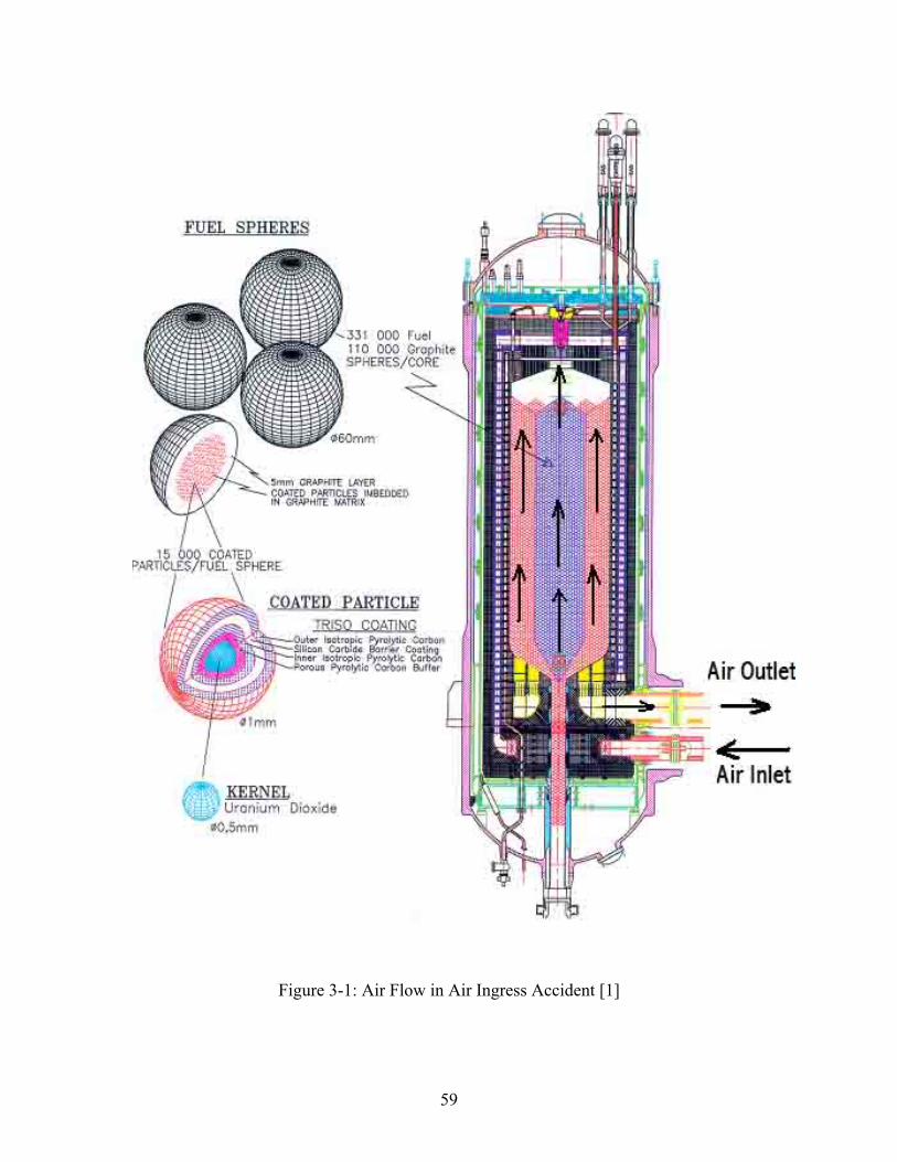
59
Figure 3-1: Air Flow in Air Ingress Accident [1]
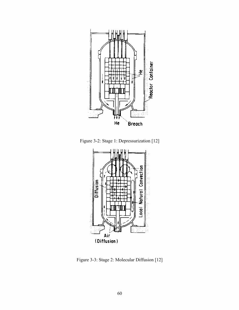
60
Figure 3-2: Stage 1: Depressurization [12]
Figure 3-3: Stage 2: Molecular Diffusion [12]
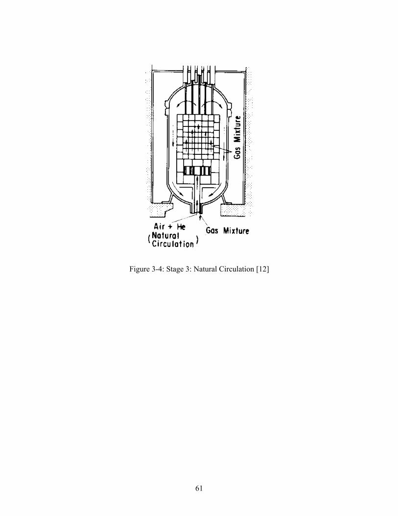
61
Figure 3-4: Stage 3: Natural Circulation [12]
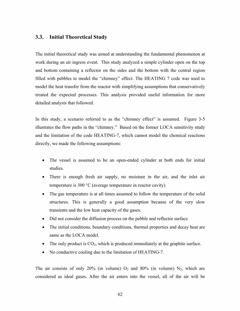
62
3.3. Initial Theoretical Study
The initial theoretical study was aimed at understanding the fundamental phenomenon at
work during an air ingress event. This study analyzed a simple cylinder open on the top
and bottom containing a reflector on the sides and the bottom with the central region
filled with pebbles to model the “chimney” effect. The HEATING 7 code was used to
model the heat transfer from the reactor with simplifying assumptions that conservatively
treated the expected processes. This analysis provided useful information for more
detailed analysis that followed.
In this study, a scenario referred to as the “chimney effect” is assumed. Figure 3-5
illustrates the flow paths in the “chimney.” Based on the former LOCA sensitivity study
and the limitation of the code HEATING-7, which cannot model the chemical reactions
directly, we made the following assumptions:
• The vessel is assumed to be an open-ended cylinder at both ends for initial
studies.
• There is enough fresh air supply, no moisture in the air, and the inlet air
temperature is 300 °C (average temperature in reactor cavity).
• The gas temperature is at all times assumed to follow the temperature of the solid
structures. This is generally a good assumption because of the very slow
transients and the low heat capacity of the gases.
• Did not consider the diffusion process on the pebble and reflector surface
• The initial conditions, boundary conditions, thermal properties and decay heat are
same as the LOCA model.
• The only product is CO2, which is produced immediately at the graphite surface.
• No conductive cooling due to the limitation of HEATING-7.
The air consists of only 20% (in volume) O2 and 80% (in volume) N2, which are
considered as ideal gases. After the air enters into the vessel, all of the air will be
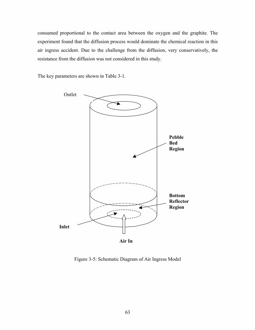
63
consumed proportional to the contact area between the oxygen and the graphite. The
experiment found that the diffusion process would dominate the chemical reaction in this
air ingress accident. Due to the challenge from the diffusion, very conservatively, the
resistance from the diffusion was not considered in this study.
The key parameters are shown in Table 3-1.
Figure 3-5: Schematic Diagram of Air Ingress Model
BottomReflectorRegion
PebbleBedRegion
Outlet
Inlet
Air In
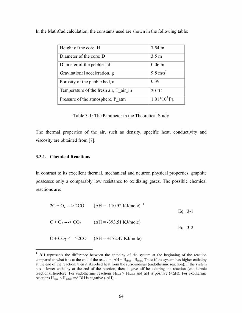
64
In the MathCad calculation, the constants used are shown in the following table:
Height of the core, H 7.54 m
Diameter of the core: D 3.5 m
Diameter of the pebbles, d 0.06 m
Gravitational acceleration, g 9.8 m/s2
Porosity of the pebble bed, ε 0.39
Temperature of the fresh air, T_air_in 20 °C
Pressure of the atmosphere, P_atm 1.01*105 Pa
Table 3-1: The Parameter in the Theoretical Study
The thermal properties of the air, such as density, specific heat, conductivity and
viscosity are obtained from [7].
3.3.1. Chemical Reactions
In contrast to its excellent thermal, mechanical and neutron physical properties, graphite
possesses only a comparably low resistance to oxidizing gases. The possible chemical
reactions are:
2C + O2 ---> 2CO (∆H = -110.52 KJ/mole) 1 Eq. 3-1
C + O2 ---> CO2 (∆H = -393.51 KJ/mole) Eq. 3-2
C + CO2 <--->2CO (∆H = +172.47 KJ/mole)
1 ∆H represents the difference between the enthalpy of the system at the beginning of the reactioncompared to what it is at the end of the reaction: ∆H = Hfinal - Hinitial Thus: if the system has higher enthalpyat the end of the reaction, then it absorbed heat from the surroundings (endothermic reaction); if the systemhas a lower enthalpy at the end of the reaction, then it gave off heat during the reaction (exothermicreaction).Therefore: For endothermic reactions Hfinal > Hinitial and ∆H is positive (+∆H); For exothermicreactions Hfinal < Hinitial and DH is negative (-∆H) .
65
Eq. 3-3
2CO + O2<--->2CO2 (∆H = - 565.98KJ/mole) Eq. 3-4
The reactions may be described as occurring in four major steps. First, oxygen gas must
be transported to the graphite surface. Second, the gas must diffuse into the graphite
pores to the oxidation location. Third, the actual chemical reaction must occur. Last, the
reaction products must diffuse out of the media to allow more oxygen to reach the
graphite [9].
Reactions of oxygen with graphite will commence at temperatures higher than 400 °C.
Countermeasures to stop the oxidation process are either to cool down the core below 400
°C by the main heat sink or to stop the air ingress. In the low-temperature regions (less
than 600 °C), chemical reactions are slow and the time required for oxygen transport may
be neglected. Oxidation is assumed to proceed uniformly throughout the graphite in this
temperature region by in-pore diffusion; then the diffusion rate determines the graphite
conversion rate. Boundary layer diffusion occurs at high temperatures. In general, the
higher the temperature, the greater the proportion of CO formed. Above 900 °C, the
products consist almost entirely of CO [21].
This is a very complicated process. Besides CO, CO2, NxOx, Carbon-oxygen surface
complex (Complex: a chemical association of two or more species (as ions or molecules)
joined usually by weak electrostatic bonds rather than covalent bonds) is formed. For the
reaction above 1000K, CO is the dominant reaction product. It proceeded through the
formation of a surface oxide, C3O4, which formed very rapidly and then decomposed in
the presence of Carbon and oxygen. At temperatures above 1100 °C the reaction favored
the formation of CO. Increasing the velocity of the gases flowing over the carbon
suppressed the formation of CO2. CO2 is the product of the secondary reaction between
CO and O2[22].
66
For the graphite pebbles and graphite reflector, one of the crucial issues is the graphite
burning. Burning is defined as self-sustained combustion of graphite. Combustion is
defined as rapid oxidation of graphite at high temperatures. Self-sustained combustion
produces enough heat to maintain the reacting species at a fixed temperature or is
sufficient to increase the temperature. From experiments, CO burns in air at
concentrations above 12.5 and below 74 volume percent [9]. The factors needed to
determine whether or not graphite can burn in air are: graphite temperature, air
temperature, air flow rate (in a limited range), ratio of heat lost to the heat produced [9].
3.3.2. Calculation Procedures
Since there are no diffusion, natural convection and chemical reaction models in the code
HEATING-7 code, many hand calculations were performed to include these effects aided
by the code MathCad code. The key assumption made in the theoretical study is that no
significant changes occur in the temperature field in several minutes due to the higher
heat capacity of the graphite and the low rate of change in the heat generation from the
chemical reactions and the decay heat. The calculation procedure is shown on Figure 3-6,
HEATING-7 was run for every 5-minute time step.
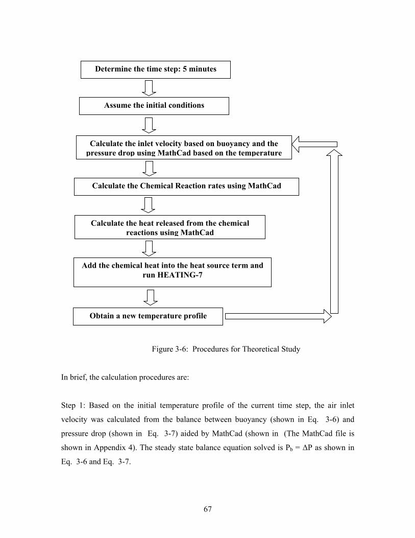
67
Figure 3-6: Procedures for Theoretical Study
In brief, the calculation procedures are:
Step 1: Based on the initial temperature profile of the current time step, the air inlet
velocity was calculated from the balance between buoyancy (shown in Eq. 3-6) and
pressure drop (shown in Eq. 3-7) aided by MathCad (shown in (The MathCad file is
shown in Appendix 4). The steady state balance equation solved is Pb = ∆P as shown in
Eq. 3-6 and Eq. 3-7.
Determine the time step: 5 minutes
Assume the initial conditions
Calculate the inlet velocity based on buoyancy and thepressure drop using MathCad based on the temperature
Calculate the Chemical Reaction rates using MathCad
Add the chemical heat into the heat source term andrun HEATING-7
Calculate the heat released from the chemicalreactions using MathCad
Obtain a new temperature profile
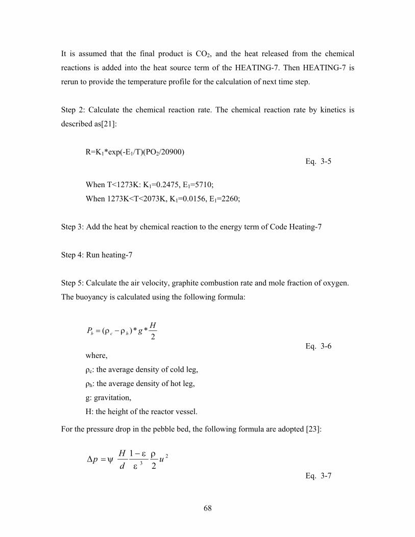
68
It is assumed that the final product is CO2, and the heat released from the chemical
reactions is added into the heat source term of the HEATING-7. Then HEATING-7 is
rerun to provide the temperature profile for the calculation of next time step.
Step 2: Calculate the chemical reaction rate. The chemical reaction rate by kinetics is
described as[21]:
R=K1*exp(-E1/T)(PO2/20900) Eq. 3-5
When T<1273K: K1=0.2475, E1=5710;
When 1273K<T<2073K, K1=0.0156, E1=2260;
Step 3: Add the heat by chemical reaction to the energy term of Code Heating-7
Step 4: Run heating-7
Step 5: Calculate the air velocity, graphite combustion rate and mole fraction of oxygen.
The buoyancy is calculated using the following formula:
2**)( HgP hcb ρρ −=
Eq. 3-6where,
ρc: the average density of cold leg,
ρh: the average density of hot leg,
g: gravitation,
H: the height of the reactor vessel.
For the pressure drop in the pebble bed, the following formula are adopted [23]:
23 2
1 udHp ρ
εε
ψ−
=∆
Eq. 3-7
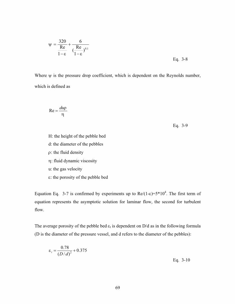
69
1.0)1Re(
6
1Re320
εε
ψ
−
+
−
=
Eq. 3-8
Where ψ is the pressure drop coefficient, which is dependent on the Reynolds number,
which is defined as
ηρdu
=Re
Eq. 3-9
H: the height of the pebble bed
d: the diameter of the pebbles
ρ: the fluid density
η: fluid dynamic viscosity
u: the gas velocity
ε: the porosity of the pebble bed
Equation Eq. 3-7 is confirmed by experiments up to Re/(1-ε)=5*104. The first term of
equation represents the asymptotic solution for laminar flow, the second for turbulent
flow.
The average porosity of the pebble bed εt is dependent on D/d as in the following formula
(D is the diameter of the pressure vessel, and d refers to the diameter of the pebbles):
375.0)/(
78.02 +=
dDtε
Eq. 3-10

70
The calculation of air inlet velocity is an iterative process. For a given temperature
distribution, the thermal properties of the air are calculated using the ideal gas formula.
Then, the air inlet velocity is adjusted in order to balance the pressure drop and the
buoyancy, and the final air inlet velocity calculated is the value at which the two forces
equal each other (as discussed in step 1).
71
3.3.3. Results and Conclusions of the Theoretical Open Cylinder Study
In this model, the air inlet velocity in the pebble bed reactor as a function of the graphite
average temperature is studied. The calculations of the pebble bed show that the air inlet
velocity does not always increase when the core is heated (Shown in Figure 3-7). The air
inlet velocity reaches its peak value at about 350 °C. As pebble temperature increases
beyond this point, the inlet air velocity goes down. This negative feedback is a very
positive result for the air ingress accident study, because the core temperature is almost
always well above 350 °C, which limits air ingress.
The reasons for this phenomenon are: first, with the increase of the temperature, the
viscosity of the gas increases. Second, if the temperature of the air becomes higher, air
density becomes lower, which would create a higher air velocity in the core (shown in
Eq. 3-6). However, the pressure loss is proportional to the velocity squared (shown in
Eq. 3-7). In other words, the resistance increases much faster than the buoyancy with the
increase of the average graphite temperature (assumed to be the gas temperature). The net
effect is a reduction in air ingress velocity with higher temperature. When the air ingress
is modeled for the open cylinder in the HEATING-7 analysis, the air ingress as a function
of time is shown on Figure 3-8.
The heat generation rate of the carbon-oxygen chemical reaction was included in the
HEATING-7 calculations which had previously included the decay heat term. Because
this is a very slow transient and because of the very low heat capacity of the gases, the
gases were assumed to have a temperature distribution similar to that of the solid
structure.
Figure 3-9 shows the peak temperature of the core of 1663 °C, 21 degree higher than the
former LOCA study. Similarly, most of the time, the peak temperature moves in the
channel 2 of the VSOP/HEATING. The small peak temperature difference is due mainly
to the low heat contribution of the chemical reactions which occur in the lower reflector.
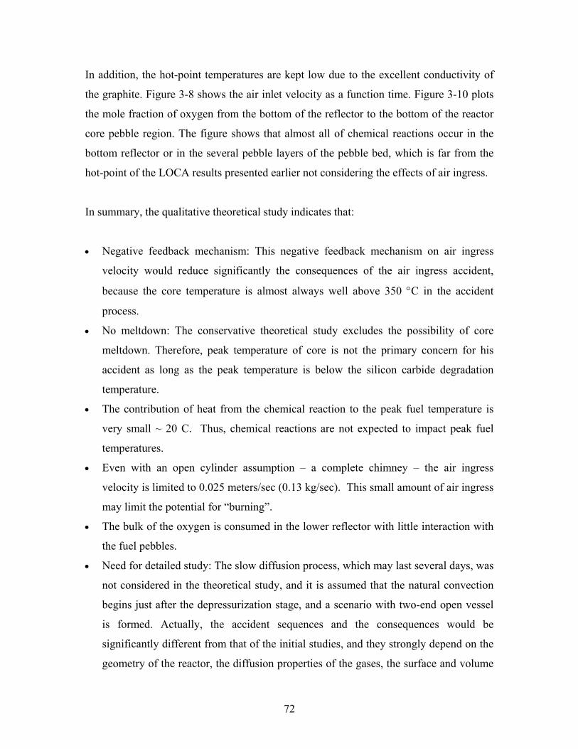
72
In addition, the hot-point temperatures are kept low due to the excellent conductivity of
the graphite. Figure 3-8 shows the air inlet velocity as a function time. Figure 3-10 plots
the mole fraction of oxygen from the bottom of the reflector to the bottom of the reactor
core pebble region. The figure shows that almost all of chemical reactions occur in the
bottom reflector or in the several pebble layers of the pebble bed, which is far from the
hot-point of the LOCA results presented earlier not considering the effects of air ingress.
In summary, the qualitative theoretical study indicates that:
• Negative feedback mechanism: This negative feedback mechanism on air ingress
velocity would reduce significantly the consequences of the air ingress accident,
because the core temperature is almost always well above 350 °C in the accident
process.
• No meltdown: The conservative theoretical study excludes the possibility of core
meltdown. Therefore, peak temperature of core is not the primary concern for his
accident as long as the peak temperature is below the silicon carbide degradation
temperature.
• The contribution of heat from the chemical reaction to the peak fuel temperature is
very small ~ 20 C. Thus, chemical reactions are not expected to impact peak fuel
temperatures.
• Even with an open cylinder assumption – a complete chimney – the air ingress
velocity is limited to 0.025 meters/sec (0.13 kg/sec). This small amount of air ingress
may limit the potential for “burning”.
• The bulk of the oxygen is consumed in the lower reflector with little interaction with
the fuel pebbles.
• Need for detailed study: The slow diffusion process, which may last several days, was
not considered in the theoretical study, and it is assumed that the natural convection
begins just after the depressurization stage, and a scenario with two-end open vessel
is formed. Actually, the accident sequences and the consequences would be
significantly different from that of the initial studies, and they strongly depend on the
geometry of the reactor, the diffusion properties of the gases, the surface and volume
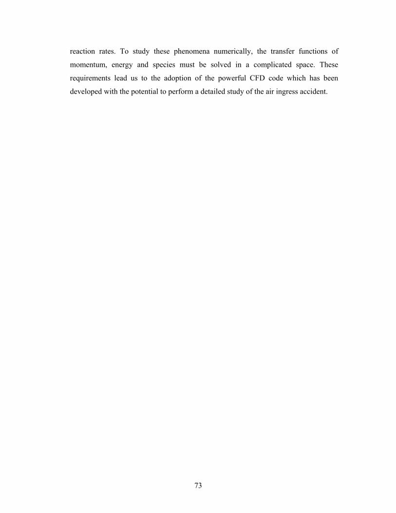
73
reaction rates. To study these phenomena numerically, the transfer functions of
momentum, energy and species must be solved in a complicated space. These
requirements lead us to the adoption of the powerful CFD code which has been
developed with the potential to perform a detailed study of the air ingress accident.
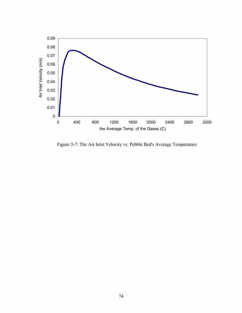
74
Figure 3-7: The Air Inlet Velocity vs. Pebble Bed's Average Temperature
0
0.01
0.02
0.03
0.04
0.05
0.06
0.07
0.08
0.09
0 400 800 1200 1600 2000 2400 2800 3200the Average Temp. of the Gases (C)
Air I
nlet
Vel
ocity
(m/s
)
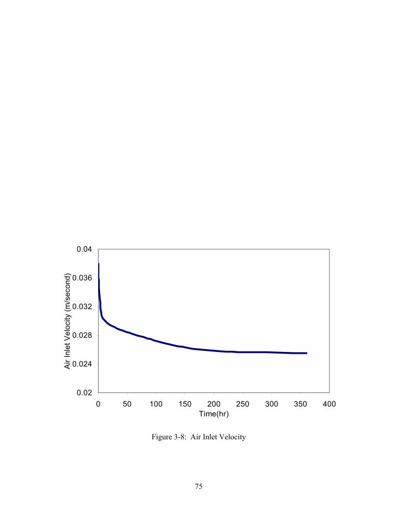
75
0.02
0.024
0.028
0.032
0.036
0.04
0 50 100 150 200 250 300 350 400Time(hr)
Air I
nlet
Vel
ocity
(m/s
econ
d)
Figure 3-8: Air Inlet Velocity
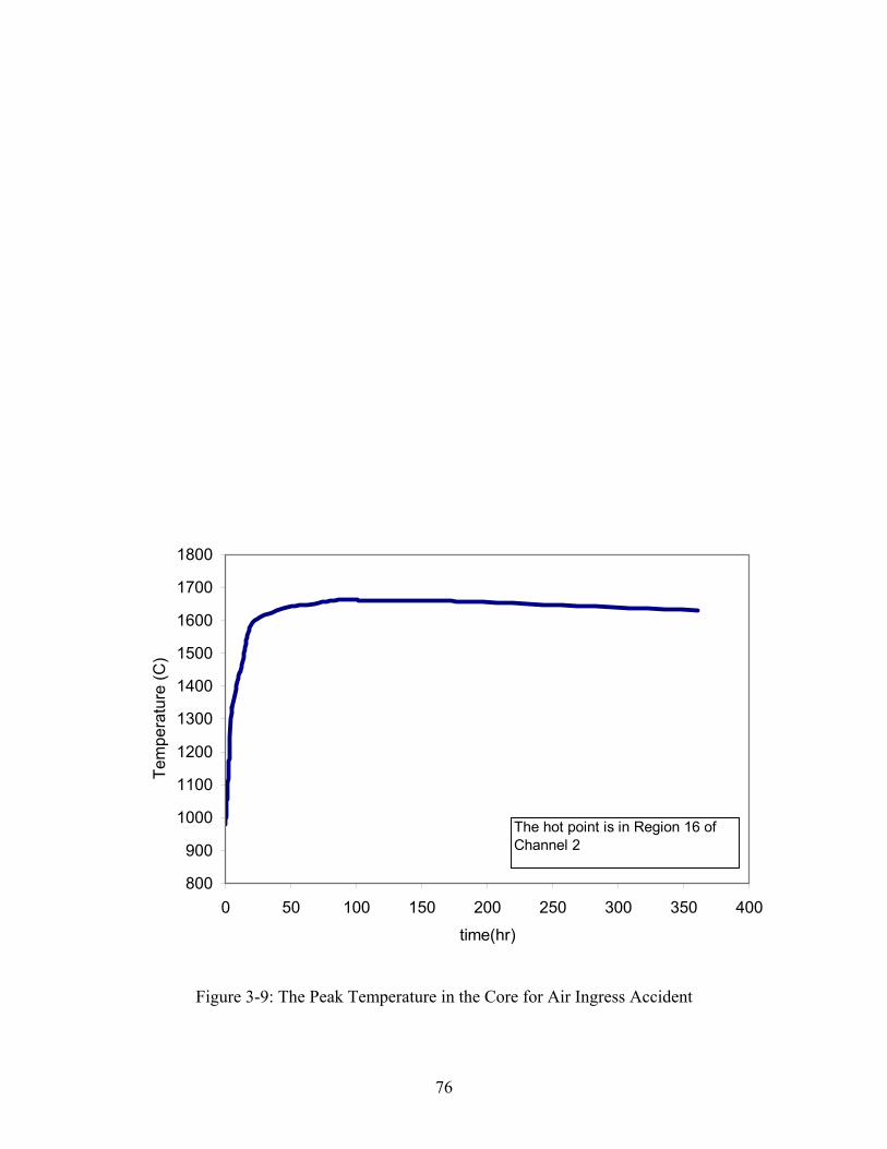
76
800
900
1000
1100
1200
1300
1400
1500
1600
1700
1800
0 50 100 150 200 250 300 350 400time(hr)
Tem
pera
ture
(C)
The hot point is in Region 16 of Channel 2
Figure 3-9: The Peak Temperature in the Core for Air Ingress Accident
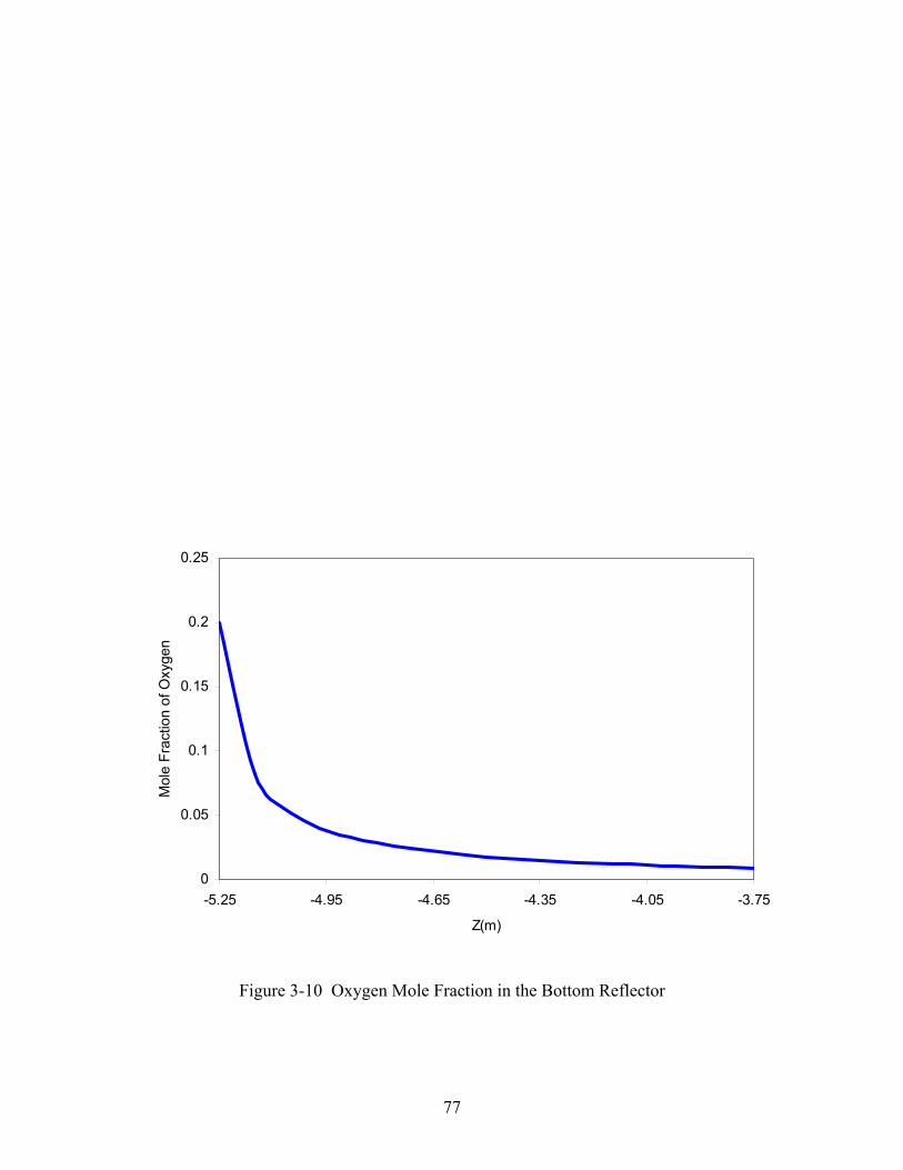
77
0
0.05
0.1
0.15
0.2
0.25
-5.25 -4.95 -4.65 -4.35 -4.05 -3.75
Z(m)
Mol
e Fr
actio
n of
Oxy
gen
Figure 3-10 Oxygen Mole Fraction in the Bottom Reflector
78
3.4. Computational Fluid Dynamics Studies
As pointed out in the previous section, phenomenological understanding of the complex
processes involved in air ingress requires sophisticated modeling tools. One such code is
FLUENT that has recently be upgraded to handle multicomponent chemical reactions.
This code will be used to develop a modeling capability for air ingress events for both
pebble and prismatic type high temperature gas reactors. In order to accomplish this
objective, the code methodology will be benchmarked against air ingress experiments
performed in Japan and Germany. The Japanese tests were focused on prismatic reactors
while the German tests examined pebble bed reactor configurations.
Based on engineering experience and previous experiments, key factors in air ingress
events are:
• Onset time of air ingress post LOCA
• Temperature of the graphite (reflector and pebbles)
• Oxidation and diffusion rates for chemical reactions
• Partial pressure of oxygen and oxidation byproducts (CO, CO2,)
• Velocity of air ingress
• Concentrations of O2, CO, CO2
• Heat removal capability from the core
FLUENT 6.0 was chosen as the tool for this analysis since it has the capability to deal
with these factors.
FLUENT is the worlds' largest commercial CFD software, which has a wide range of
industrial applications and world wide consulting services. Besides its capacities to model
the heat transfer and mass diffusion, surface reaction model was added in its latest
version – FLUENT 6.0. FLUENT is a standard CFD tool used in many complex heat
transfer calculations. The FLUENT 6 version has been upgraded to allow for the
79
introduction of chemical reactions through the use of user defined functions that can
simulate graphite and oxygen reactions in addition to including all forms of heat transfer
including convection. This more rigorous tool will allow more confidence in the results
of air ingress analysis.
In order to understand all of the key processes (diffusion, natural convection, and
chemical reactions) involved in the air ingress accident, three experiments by JAERI
(Japan Atomic Energy Research Institute) and one experiment by Julich Institute of
Germany will be studied with increasing complexities using the CFD code FLUENT 6.0.
3.4.1. JAERI Air Ingress Experiments[11][12][13]
In order to understand all of the key processes (diffusion, natural convection, and
chemical reactions) involved in the air ingress accident, three experiments by JAERI
(Japan Atomic Energy Research Institute) were studied with FLUENT 6.0.
3.4.1.1. Isothermal JAERI Experiment – Diffusion
3.4.1.1.1. Experiment Description
A rough sketch of the experimental apparatus is shown in Figure 3-11 and Figure 3-12.
The apparatus consists of a reverse U-Shape tube and a gas tank. A bent pipe connecting
the two pipes is also heated. The inner diameter of the tube is 52.7mm.
This experiment was designed to test the first stage of air ingress – diffusion . The entire
experiment was conducted at isothermal conditions at 18 C. [6] The two gases used were
helium in the tube and nitrogen in the lower tank.
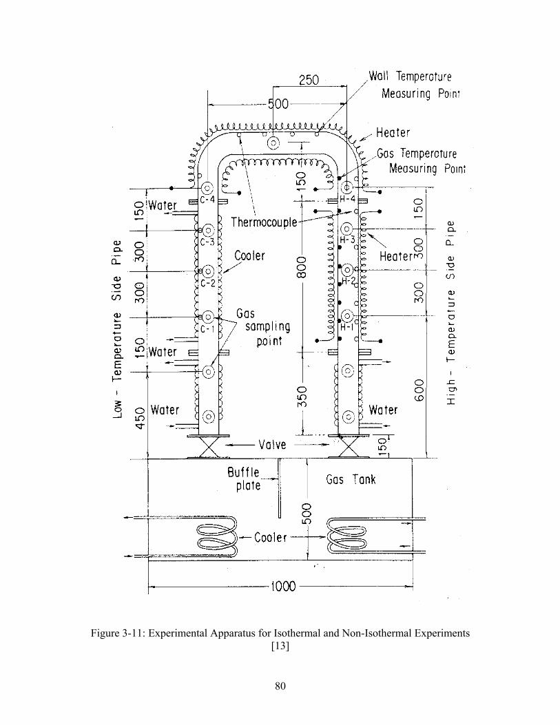
80
Figure 3-11: Experimental Apparatus for Isothermal and Non-Isothermal Experiments[13]
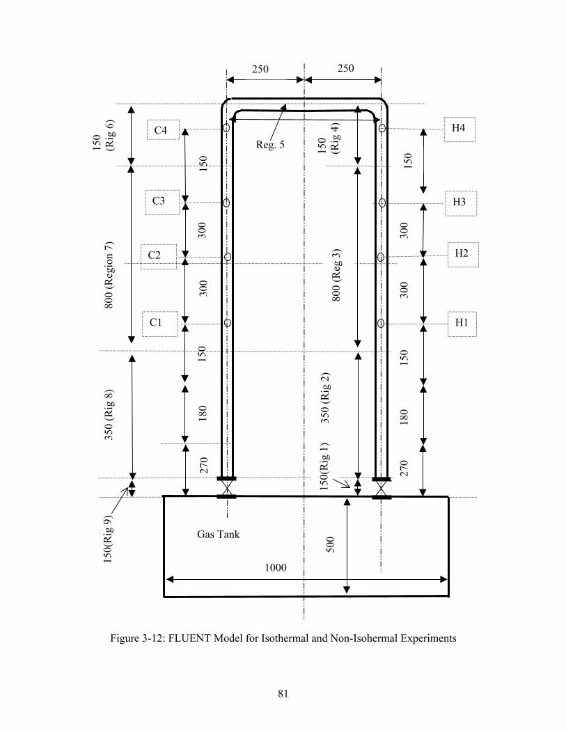
81
Figure 3-12: FLUENT Model for Isothermal and Non-Isohermal Experiments
Reg. 5
H3
H2
H1
H4
150
300
300
150
180
270
C3
C2
C4
C1
150
300
300
150
180
270
250 250
500
150
(Rig
4)
800
(Reg
3)
350
(Rig
2)
150(
Rig
1)
Gas Tank
150
(Rig
6)
800
(Reg
ion
7)35
0 (R
ig 8
)15
0(R
ig 9
)
1000
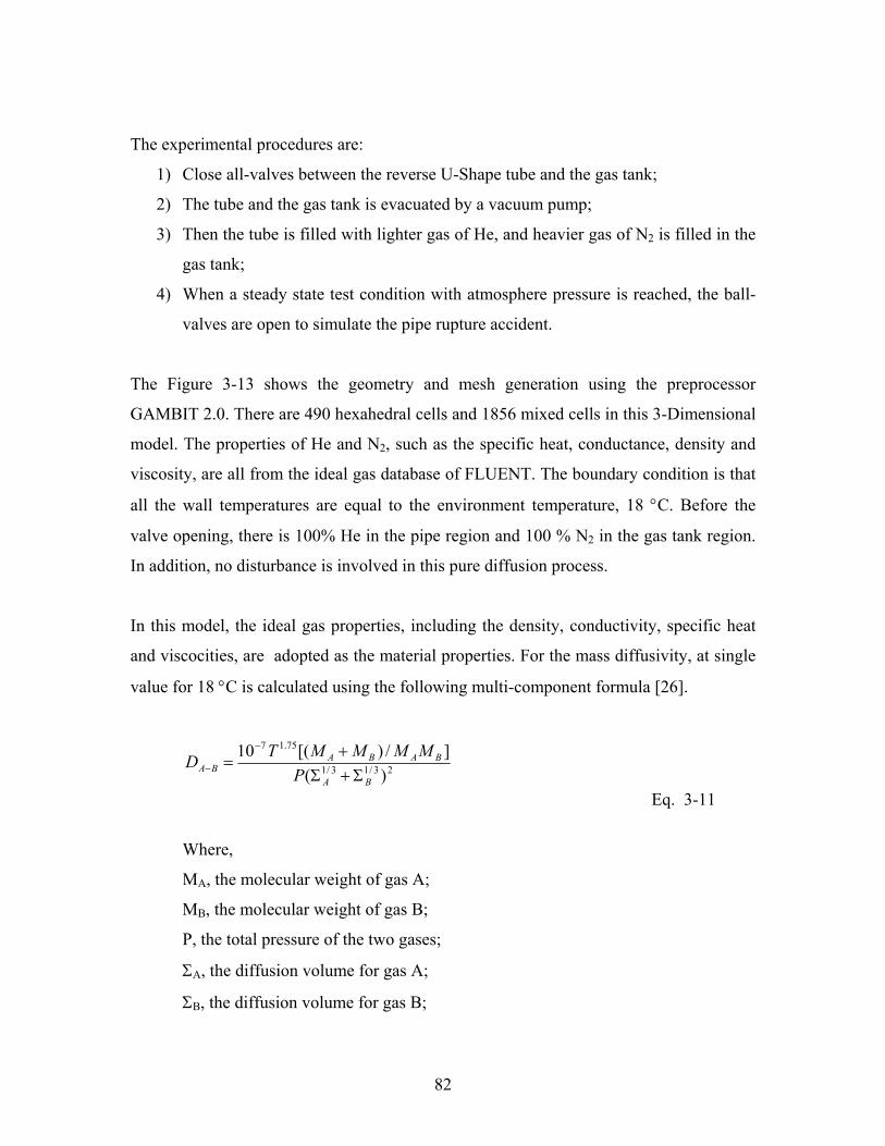
82
The experimental procedures are:
1) Close all-valves between the reverse U-Shape tube and the gas tank;
2) The tube and the gas tank is evacuated by a vacuum pump;
3) Then the tube is filled with lighter gas of He, and heavier gas of N2 is filled in the
gas tank;
4) When a steady state test condition with atmosphere pressure is reached, the ball-
valves are open to simulate the pipe rupture accident.
The Figure 3-13 shows the geometry and mesh generation using the preprocessor
GAMBIT 2.0. There are 490 hexahedral cells and 1856 mixed cells in this 3-Dimensional
model. The properties of He and N2, such as the specific heat, conductance, density and
viscosity, are all from the ideal gas database of FLUENT. The boundary condition is that
all the wall temperatures are equal to the environment temperature, 18 °C. Before the
valve opening, there is 100% He in the pipe region and 100 % N2 in the gas tank region.
In addition, no disturbance is involved in this pure diffusion process.
In this model, the ideal gas properties, including the density, conductivity, specific heat
and viscocities, are adopted as the material properties. For the mass diffusivity, at single
value for 18 °C is calculated using the following multi-component formula [26].
23/13/1
75.17
)(]/)[(10
BA
BABABA P
MMMMTDΣ+Σ
+=
−
−
Eq. 3-11
Where,
MA, the molecular weight of gas A;
MB, the molecular weight of gas B;
P, the total pressure of the two gases;
ΣA, the diffusion volume for gas A;
ΣB, the diffusion volume for gas B;
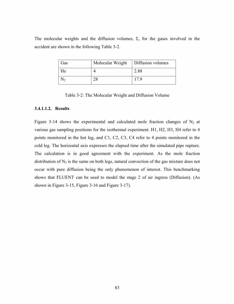
83
The molecular weights and the diffusion volumes, Σ, for the gases involved in the
accident are shown in the following Table 3-2.
Gas Molecular Weight Diffusion volumes
He 4 2.88
N2 28 17.9
Table 3-2: The Molecular Weight and Diffusion Volume
3.4.1.1.2. Results
Figure 3-14 shows the experimental and calculated mole fraction changes of N2 at
various gas sampling positions for the isothermal experiment. H1, H2, H3, H4 refer to 4
points monitored in the hot leg, and C1, C2, C3, C4 refer to 4 points monitored in the
cold leg. The horizontal axis expresses the elapsed time after the simulated pipe rupture.
The calculation is in good agreement with the experiment. As the mole fraction
distribution of N2 is the same on both legs, natural convection of the gas mixture does not
occur with pure diffusion being the only phenomenon of interest. This benchmarking
shows that FLUENT can be used to model the stage 2 of air ingress (Diffusion). (As
shown in Figure 3-15, Figure 3-16 and Figure 3-17).

84
Figure 3-13: The Structured Meshes for Isothermal and Non-Isothermal Experiments
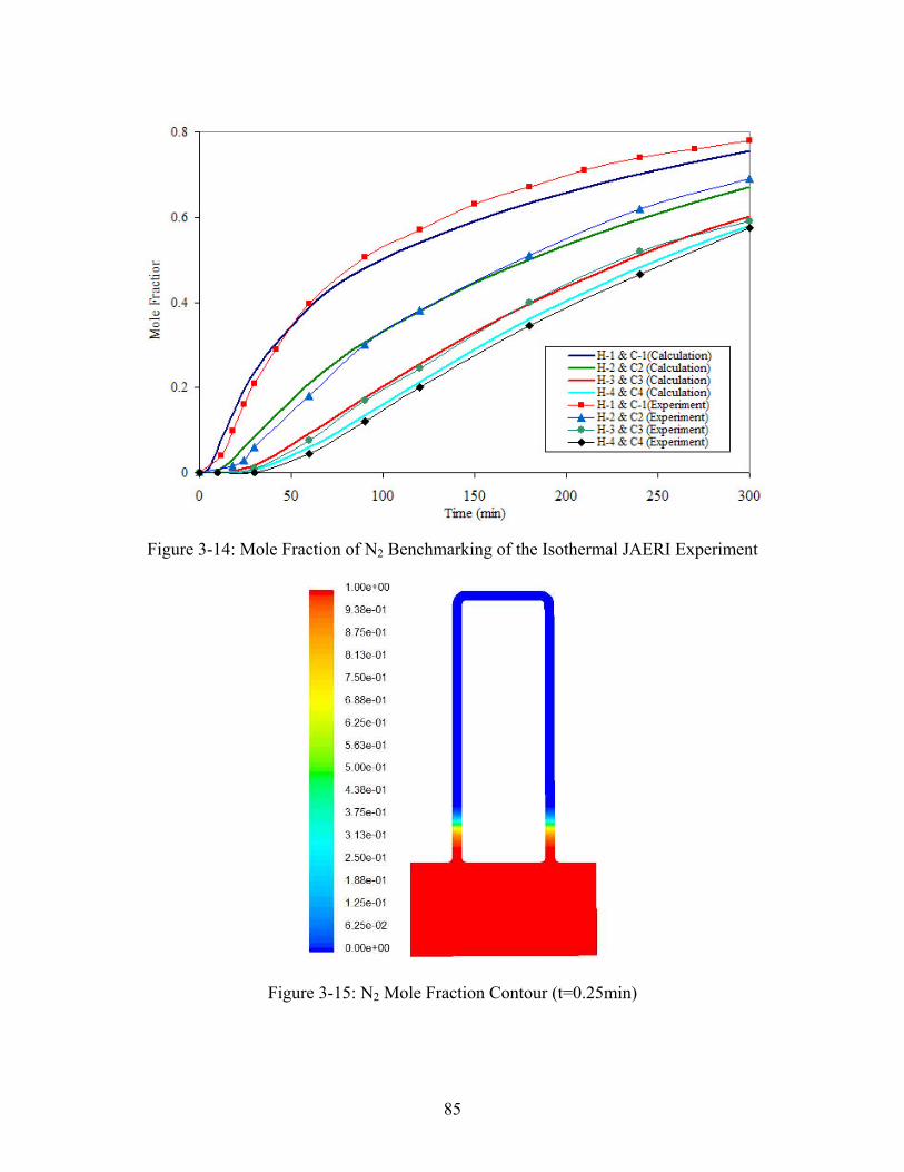
85
Figure 3-14: Mole Fraction of N2 Benchmarking of the Isothermal JAERI Experiment
Figure 3-15: N2 Mole Fraction Contour (t=0.25min)
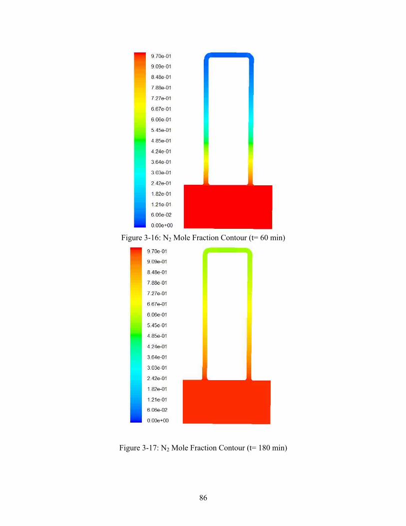
86
Figure 3-16: N2 Mole Fraction Contour (t= 60 min)
Figure 3-17: N2 Mole Fraction Contour (t= 180 min)
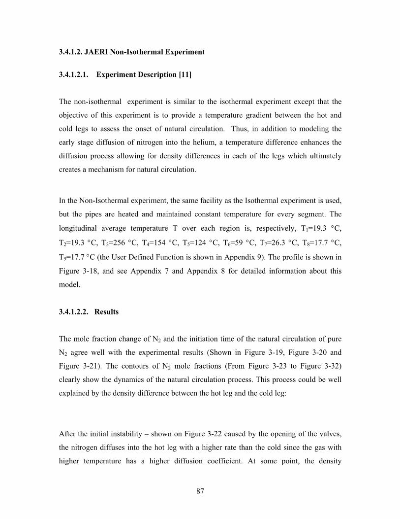
87
3.4.1.2. JAERI Non-Isothermal Experiment
3.4.1.2.1. Experiment Description [11]
The non-isothermal experiment is similar to the isothermal experiment except that the
objective of this experiment is to provide a temperature gradient between the hot and
cold legs to assess the onset of natural circulation. Thus, in addition to modeling the
early stage diffusion of nitrogen into the helium, a temperature difference enhances the
diffusion process allowing for density differences in each of the legs which ultimately
creates a mechanism for natural circulation.
In the Non-Isothermal experiment, the same facility as the Isothermal experiment is used,
but the pipes are heated and maintained constant temperature for every segment. The
longitudinal average temperature T over each region is, respectively, T1=19.3 °C,
T2=19.3 °C, T3=256 °C, T4=154 °C, T5=124 °C, T6=59 °C, T7=26.3 °C, T8=17.7 °C,
T9=17.7 °C (the User Defined Function is shown in Appendix 9). The profile is shown in
Figure 3-18, and see Appendix 7 and Appendix 8 for detailed information about this
model.
3.4.1.2.2. Results
The mole fraction change of N2 and the initiation time of the natural circulation of pure
N2 agree well with the experimental results (Shown in Figure 3-19, Figure 3-20 and
Figure 3-21). The contours of N2 mole fractions (From Figure 3-23 to Figure 3-32)
clearly show the dynamics of the natural circulation process. This process could be well
explained by the density difference between the hot leg and the cold leg:
After the initial instability – shown on Figure 3-22 caused by the opening of the valves,
the nitrogen diffuses into the hot leg with a higher rate than the cold since the gas with
higher temperature has a higher diffusion coefficient. At some point, the density
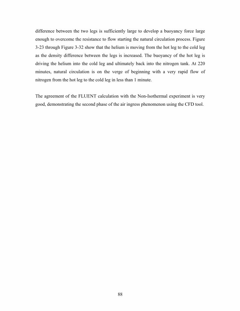
88
difference between the two legs is sufficiently large to develop a buoyancy force large
enough to overcome the resistance to flow starting the natural circulation process. Figure
3-23 through Figure 3-32 show that the helium is moving from the hot leg to the cold leg
as the density difference between the legs is increased. The buoyancy of the hot leg is
driving the helium into the cold leg and ultimately back into the nitrogen tank. At 220
minutes, natural circulation is on the verge of beginning with a very rapid flow of
nitrogen from the hot leg to the cold leg in less than 1 minute.
The agreement of the FLUENT calculation with the Non-Isothermal experiment is very
good, demonstrating the second phase of the air ingress phenomenon using the CFD tool.
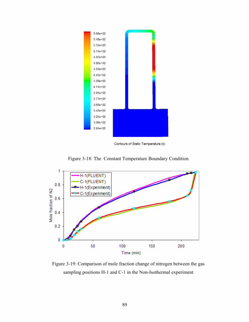
89
Figure 3-18: The Constant Temperature Boundary Condition
Figure 3-19: Comparison of mole fraction change of nitrogen between the gas
sampling positions H-1 and C-1 in the Non-Isothermal experiment
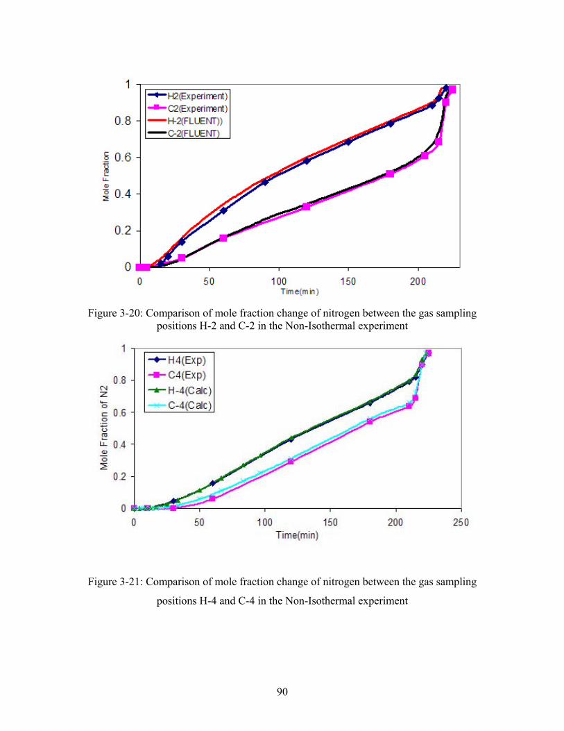
90
Figure 3-20: Comparison of mole fraction change of nitrogen between the gas samplingpositions H-2 and C-2 in the Non-Isothermal experiment
Figure 3-21: Comparison of mole fraction change of nitrogen between the gas sampling
positions H-4 and C-4 in the Non-Isothermal experiment
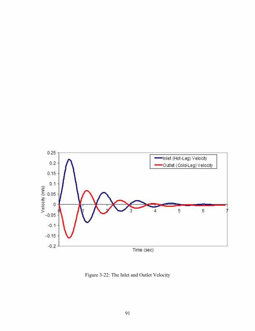
91
Figure 3-22: The Inlet and Outlet Velocity
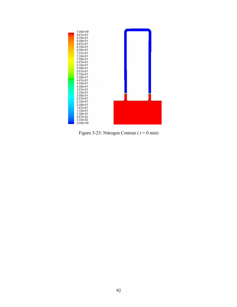
92
Figure 3-23: Nitrogen Contour ( t = 0 min)

93
Figure 3-24: Nitrogen Contour (t=1.6 min)
Figure 3-25: Nitrogen Contour (t=75.5 min)
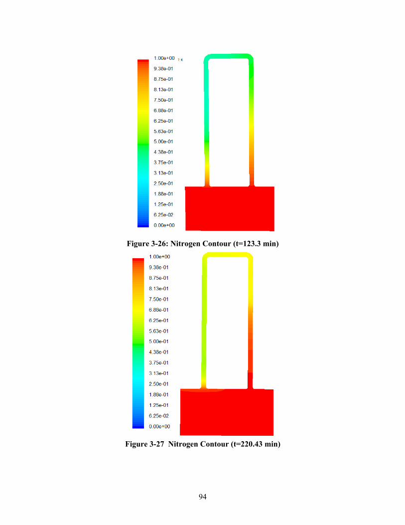
94
Figure 3-26: Nitrogen Contour (t=123.3 min)
Figure 3-27 Nitrogen Contour (t=220.43 min)
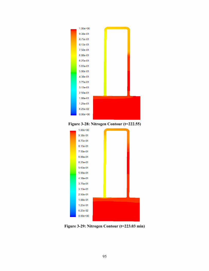
95
Figure 3-28: Nitrogen Contour (t=222.55)
Figure 3-29: Nitrogen Contour (t=223.03 min)
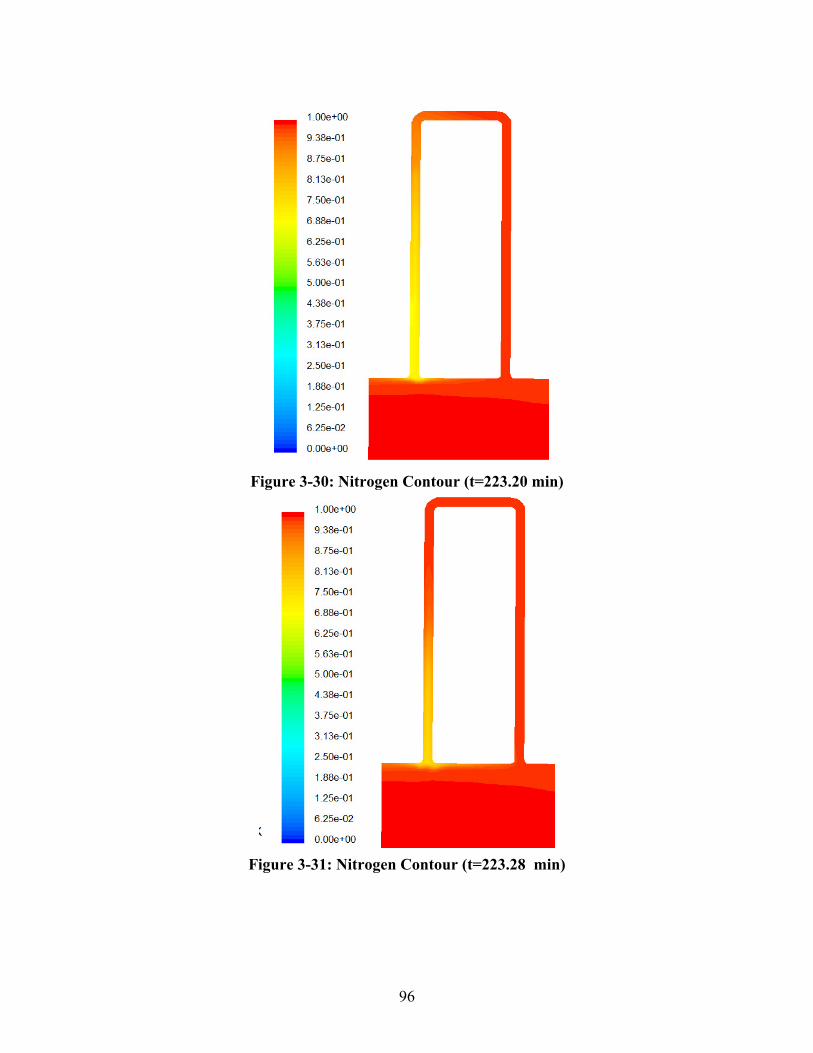
96
Figure 3-30: Nitrogen Contour (t=223.20 min)
Figure 3-31: Nitrogen Contour (t=223.28 min)
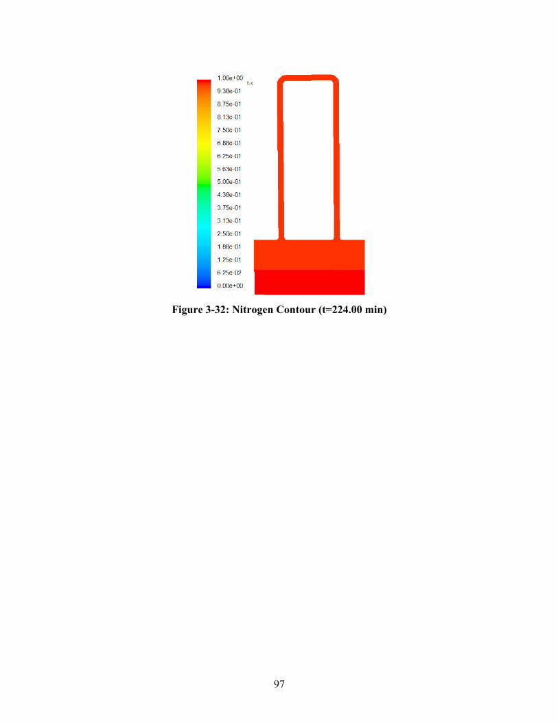
97
Figure 3-32: Nitrogen Contour (t=224.00 min)
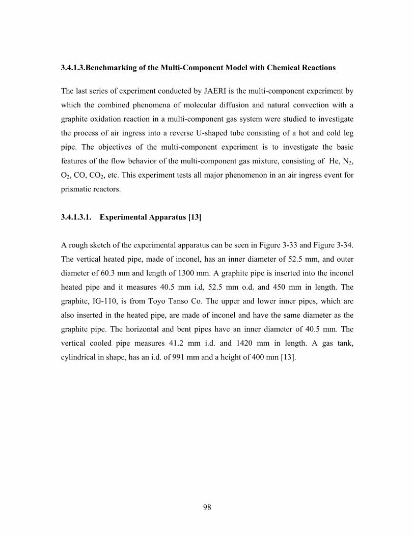
98
3.4.1.3. Benchmarking of the Multi-Component Model with Chemical Reactions
The last series of experiment conducted by JAERI is the multi-component experiment by
which the combined phenomena of molecular diffusion and natural convection with a
graphite oxidation reaction in a multi-component gas system were studied to investigate
the process of air ingress into a reverse U-shaped tube consisting of a hot and cold leg
pipe. The objectives of the multi-component experiment is to investigate the basic
features of the flow behavior of the multi-component gas mixture, consisting of He, N2,
O2, CO, CO2, etc. This experiment tests all major phenomenon in an air ingress event for
prismatic reactors.
3.4.1.3.1. Experimental Apparatus [13]
A rough sketch of the experimental apparatus can be seen in Figure 3-33 and Figure 3-34.
The vertical heated pipe, made of inconel, has an inner diameter of 52.5 mm, and outer
diameter of 60.3 mm and length of 1300 mm. A graphite pipe is inserted into the inconel
heated pipe and it measures 40.5 mm i.d, 52.5 mm o.d. and 450 mm in length. The
graphite, IG-110, is from Toyo Tanso Co. The upper and lower inner pipes, which are
also inserted in the heated pipe, are made of inconel and have the same diameter as the
graphite pipe. The horizontal and bent pipes have an inner diameter of 40.5 mm. The
vertical cooled pipe measures 41.2 mm i.d. and 1420 mm in length. A gas tank,
cylindrical in shape, has an i.d. of 991 mm and a height of 400 mm [13].
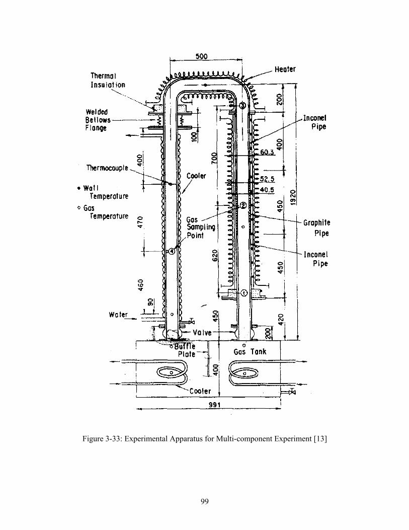
99
Figure 3-33: Experimental Apparatus for Multi-component Experiment [13]
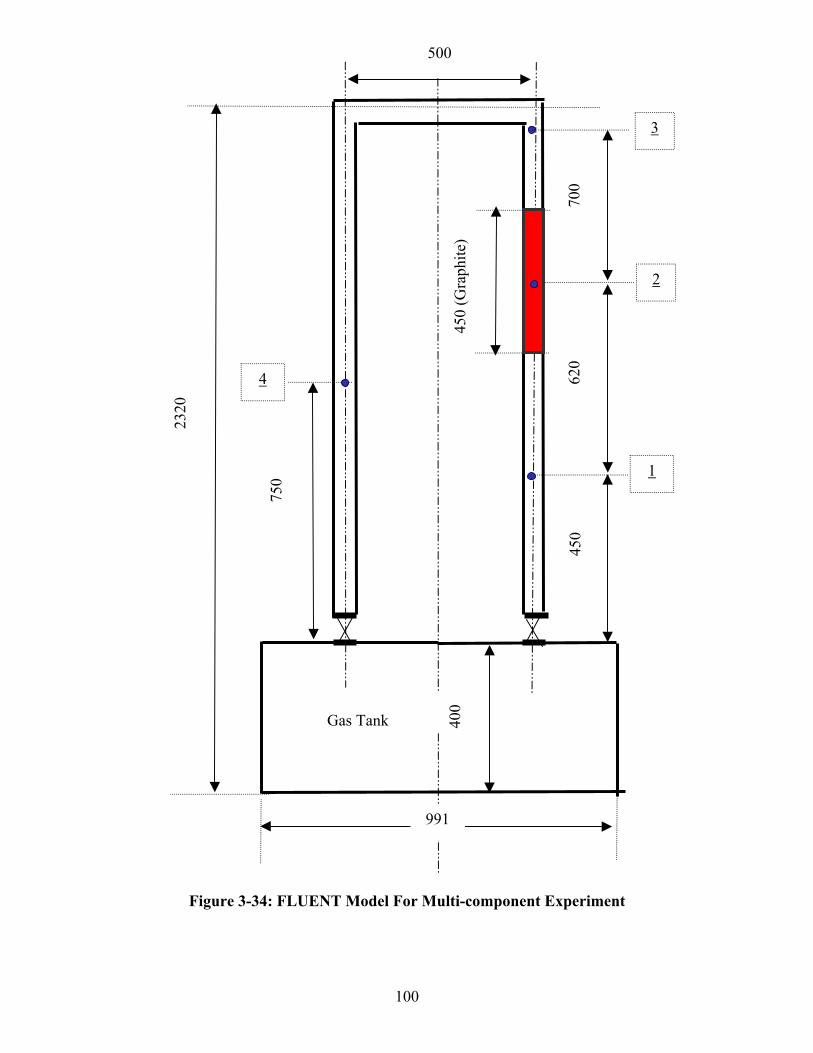
100
Figure 3-34: FLUENT Model For Multi-component Experiment
2
1
620
450
400
Gas Tank
3
991
700
4
750
2320
450
(Gra
phite
)
500
101
The mole fraction of each gas species and the density of the gas mixture were measured
at four sampling points shown in Figure 3-34. The density of the gas mixture, the mole
fraction of O2, CO and CO2 were measured using a gas analyzer (Yokogawa: density-
Vibro gas analyzer DG8, O2-Electrochemical analyzer 6234, CO and CO2-infrared rays
analyzer IR21).
The temperature distribution of the pipe wall was measured by 18 K-type thermocouples
and the temperatures of the gas mixture were also measured at nine points using K-type
thermocouples. The signals of the voltage from the thermocouples and the gas analyzer
were digitallyt sampled and read using a data acquisition control unit (Scanner and DVM:
Advantest TR2730 & TR2731). These units were controlled by a Hewlett-Packard Series
9000 Model 216 computer. It is assumed that the onset time of the natural circulation of
air is the time when the gas temperature at the cooled pipe exceeds 100 °C. As the natural
circulation of N2 occurs, the gas temperature at the upper part of the cooled pipe increases
rapidly. The time required for the gas temperature to be increased from 20 to 100°C is
about 10 seconds.
In consideration of the errors induced by the thermocouples, scanner junction and DVM
accuracy, the entire accuracy of the temperature measurement was within ±0.3°C. The
measurement accuracy of the density analyzer and the concentration analyzer(O2, CO,
CO2) were ±1% F.S. and ±1.7% F.S., respectively. The relative uncertainty in the density
of the gas mixture was found to be ±4%. The uncertainties in the mole fraction of O2,
CO, and CO2 were found to be ±2.3%, ±4.4% and ±4.4%, respectively. The uncertainty
in the onset time of the natural circulation of air was estimated to be 12% [13].
3.4.1.3.2. Experimental Procedure [13]
The experimental procedures are as follows: The ball valves between the reverse U-
shaped tube and the gas tank were closed and the tube was evacuated using a vacuum
pump. Helium and air was injected into the tube and the gas tank, respectively. Then, the
high-temperature side pipe and the connecting pipe were heated from about 400 °C to
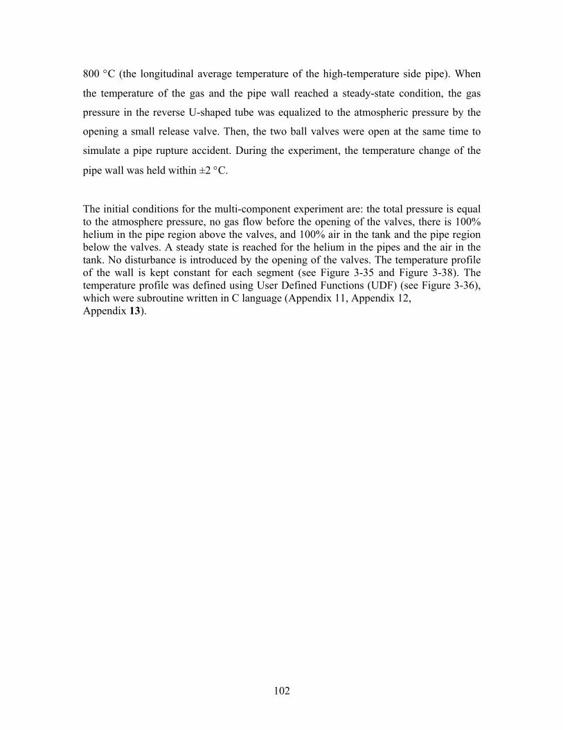
102
800 °C (the longitudinal average temperature of the high-temperature side pipe). When
the temperature of the gas and the pipe wall reached a steady-state condition, the gas
pressure in the reverse U-shaped tube was equalized to the atmospheric pressure by the
opening a small release valve. Then, the two ball valves were open at the same time to
simulate a pipe rupture accident. During the experiment, the temperature change of the
pipe wall was held within ±2 °C.
The initial conditions for the multi-component experiment are: the total pressure is equalto the atmosphere pressure, no gas flow before the opening of the valves, there is 100%helium in the pipe region above the valves, and 100% air in the tank and the pipe regionbelow the valves. A steady state is reached for the helium in the pipes and the air in thetank. No disturbance is introduced by the opening of the valves. The temperature profileof the wall is kept constant for each segment (see Figure 3-35 and Figure 3-38). Thetemperature profile was defined using User Defined Functions (UDF) (see Figure 3-36),which were subroutine written in C language (Appendix 11, Appendix 12, Appendix 13).
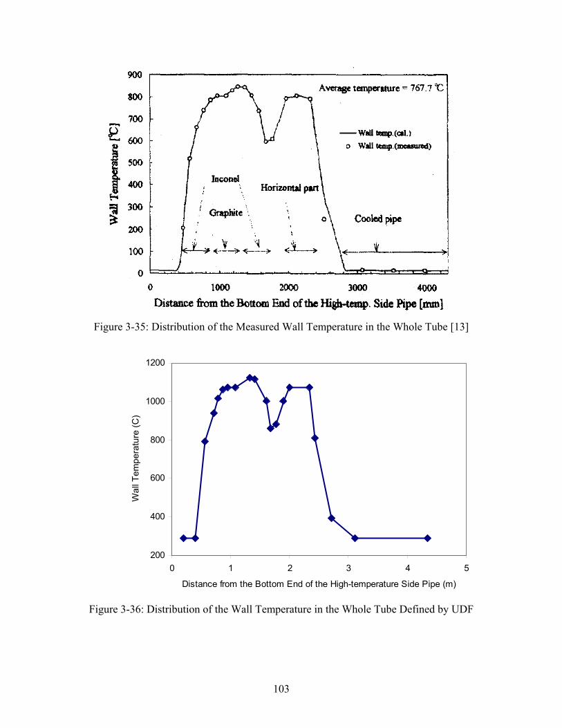
103
Figure 3-35: Distribution of the Measured Wall Temperature in the Whole Tube [13]
200
400
600
800
1000
1200
0 1 2 3 4 5
Distance from the Bottom End of the High-temperature Side Pipe (m)
Wal
l Tem
pera
ture
(C)
Figure 3-36: Distribution of the Wall Temperature in the Whole Tube Defined by UDF

104
Figure 3-37: The Temperature Profile for the Multi-component Experiment
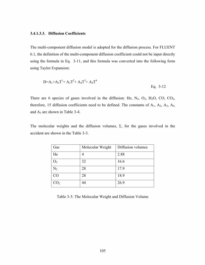
105
3.4.1.3.3. Diffusion Coefficients
The multi-component diffusion model is adopted for the diffusion process. For FLUENT
6.1, the definition of the multi-component diffusion coefficient could not be input directly
using the formula in Eq. 3-11, and this formula was converted into the following form
using Taylor Expansion:
D=A1+A2T1+ A3T2+ A4T3+ A4T4 Eq. 3-12
There are 6 species of gases involved in the diffusion: He, N2, O2, H2O, CO, CO2,
therefore, 15 diffusion coefficients need to be defined. The constants of A1, A2, A3, A4,
and A5 are shown in Table 3-4.
The molecular weights and the diffusion volumes, Σ, for the gases involved in the
accident are shown in the Table 3-3.
Gas Molecular Weight Diffusion volumes
He 4 2.88
O2 32 16.6
N2 28 17.9
CO 28 18.9
CO2 44 26.9
Table 3-3: The Molecular Weight and Diffusion Volume
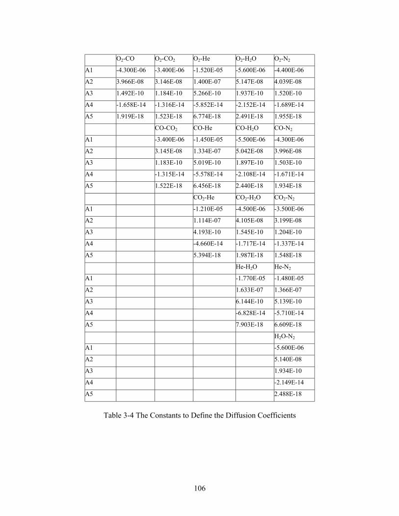
106
O2-CO O2-CO2 O2-He O2-H2O O2-N2
A1 -4.300E-06 -3.400E-06 -1.520E-05 -5.600E-06 -4.400E-06
A2 3.966E-08 3.146E-08 1.400E-07 5.147E-08 4.039E-08
A3 1.492E-10 1.184E-10 5.266E-10 1.937E-10 1.520E-10
A4 -1.658E-14 -1.316E-14 -5.852E-14 -2.152E-14 -1.689E-14
A5 1.919E-18 1.523E-18 6.774E-18 2.491E-18 1.955E-18
CO-CO2 CO-He CO-H2O CO-N2
A1 -3.400E-06 -1.450E-05 -5.500E-06 -4.300E-06
A2 3.145E-08 1.334E-07 5.042E-08 3.996E-08
A3 1.183E-10 5.019E-10 1.897E-10 1.503E-10
A4 -1.315E-14 -5.578E-14 -2.108E-14 -1.671E-14
A5 1.522E-18 6.456E-18 2.440E-18 1.934E-18
CO2-He CO2-H2O CO2-N2
A1 -1.210E-05 -4.500E-06 -3.500E-06
A2 1.114E-07 4.105E-08 3.199E-08
A3 4.193E-10 1.545E-10 1.204E-10
A4 -4.660E-14 -1.717E-14 -1.337E-14
A5 5.394E-18 1.987E-18 1.548E-18
He-H2O He-N2
A1 -1.770E-05 -1.480E-05
A2 1.633E-07 1.366E-07
A3 6.144E-10 5.139E-10
A4 -6.828E-14 -5.710E-14
A5 7.903E-18 6.609E-18
H2O-N2
A1 -5.600E-06
A2 5.140E-08
A3 1.934E-10
A4 -2.149E-14
A5 2.488E-18
Table 3-4 The Constants to Define the Diffusion Coefficients
107
3.4.1.3.4. Chemical Reaction Rates [13]
The graphite oxidation reaction(C-O2)reaction) and the carbon monoxide combustion
(CO-O2 reaction) are taken into account. The chemical equation of the graphite reaction
is expressed as [13]:
C + z · O2 x · CO +y · CO2 Eq. 3-13
The reaction rate is described as
nooc p
RTEKr
2)exp( 0
0 −=−
Eq. 3-14
where,
K0=360, reaction constant,
E0=209 [kJmole-1], activation energy,
PO2, the oxygen partial pressure.
The units of R, T, rc-o and PO2 are [Jmole-1K-1], [K], [kg.kg-1s-1] and [pa], respectively.
The value of the exponential index, n, in terms of the oxygen partial pressure ranges from
0.75 to 1 for PGX2. For this type of graphite, the value used in this analysis is 1 following
JAERI’s recommendation[13].
The production ratio of CO to CO2 (x/y=A) is correlated as follows:
)exp( 11 RT
EKA −=
Eq. 3-15K1=7943,
E1=78.3 [kJmole-1], activation energy,
2 The name of the graphite used in the multi-component experiment.
108
Where K1 is the constant and E1 the activation energy. The reported ratios differ over a
wide range because the production ratio depends on experimental conditions, such as the
catalytic effects of the impurities contained in the graphite and the grade of graphite.
There is no data on these effects, thus, it is assumed that the production ratio of CO to
CO2 is constant since the wall temperature is assumed constant.
The mole number for the reaction term of O2 and for the generation term of CO and CO2
of Eq. 3-13 can be obtained from the following relation, respectively [13].
)1(22
2 ++
==AANz o
Eq. 3-16
1+==AANx co
Eq. 3-17
11
2 +==A
Nx co
Eq. 3-18
The chemical equation of the CO combustion is expressed as [13]
2221 COOCO →+
Eq. 3-19
].[... 135.02
5.022
−−−−= smmolCCCr
dtdC
OHocoococo
Eq. 3-20
where,
)exp( 222 RT
EKr oco −=−
Eq. 3-21
109
co
co
co
coco MMC ωρρ .
==
Eq. 3-22
2
2
2
22
.
o
o
o
oO MMC ωρρ
==
Eq. 3-23
co
co
co
coco MMC ωρρ .
==
Eq. 3-24
OHOHOH XM
XCC222
.. ρ==
Eq. 3-25
Here, K2=1.3x10⁸ [m3.mol-1.s-1], E2=126[kJ.mol-1].
3.4.1.3.5. Mesh
A grid adaptation of FLUENT was used in this multi-component model. In the pipe and
tank region near the ball valve, denser meshes are generated since the species gradients
would be higher in these regions. In addition, through grid adaptation technology, the
mesh regions with higher mesh densities move with the species gradient frontiers which
determines the convergence speed of every time step. For the grid adaptation technology,
see the Chapter 23 of Reference [17].
3.4.1.3.6. Results
In the transient calculation of the multi-component experiment, lower time steps, 0.001-
0.01 second, are used for the initial simulation due to the higher species concentration
gradients near the ball valve regions. With the decrease of the gradients, time steps are
increased to 1.5 seconds. Compared with the former two cases, Isothermal and Non-
Isothermal experiments, this is much more time consuming calculation since besides the
heat transfer and the natural convection, complicated mass transport and chemical
reactions are modeled in the multi-component. For detailed model summary, see the
110
Appendix 10. Figure 3-38, Figure 3-39 and Figure 3-40 show the comparisons between
the calculation and the experiment for the mole fraction changes of O2, CO and CO2 at
various locations in the experiment. The results show quite good agreement with
experiment at the measured points for O2, CO and CO2 mole fractions. The FLUENT
code also predicts well the onset of natural circulation.
Shown on Figure 3-38 are the point 1 mole fractions calculated compared to the
experimental results for O2, CO and CO2. While the oxygen is slightly over-predicted
below the heated graphite region, there is good agreement with the CO and CO2 mole
fractions as a function of time. The onset of natural circulation is predicted to within less
10% of the actual experimental result.
Shown on Figure 3-39 are the point 3 mole fractions just above the heated graphite zone.
This figure shows that all of the oxygen is consumed in the graphite zone until natural
circulation begins rapidly. This figure also shows that the predominant species at Point 3
is CO2 and that the concentration of CO is relatively low (less than 3%). This potentially
an important finding relative to “burning” since CO is subject to oxidation forming CO2
which can be considered “burning.
At Point 4, on the cold leg, Figure 3-40 shows that the oxygen level initially increases
due to cold leg diffusion but it is then reduced by the CO and CO2 gas mixture which
diffuses to Point 4. In addition, some of the oxygen reacts with the CO to form CO2
increasing its mole fraction while reducing the oxygen.
Once natural circulation starts, the dominate species is oxygen as shown on all figures
with the concentrations of CO and CO2 dropping quickly and dramatically. During the
natural circulation phase, the air ingress velocity is calculated to be 0.04m/s. In addition,
the graphite consumption rate shown on Figure 3-41 dramatically increases as expected
to 2.3E-07 kg/s from 1.3E-8 kg/s during the diffusion process. This higher reaction rate is
due to the surface chemical reaction rather than the volumetric diffusion reaction
experienced during the diffusion stage. This is because the gas mixture moves at a higher
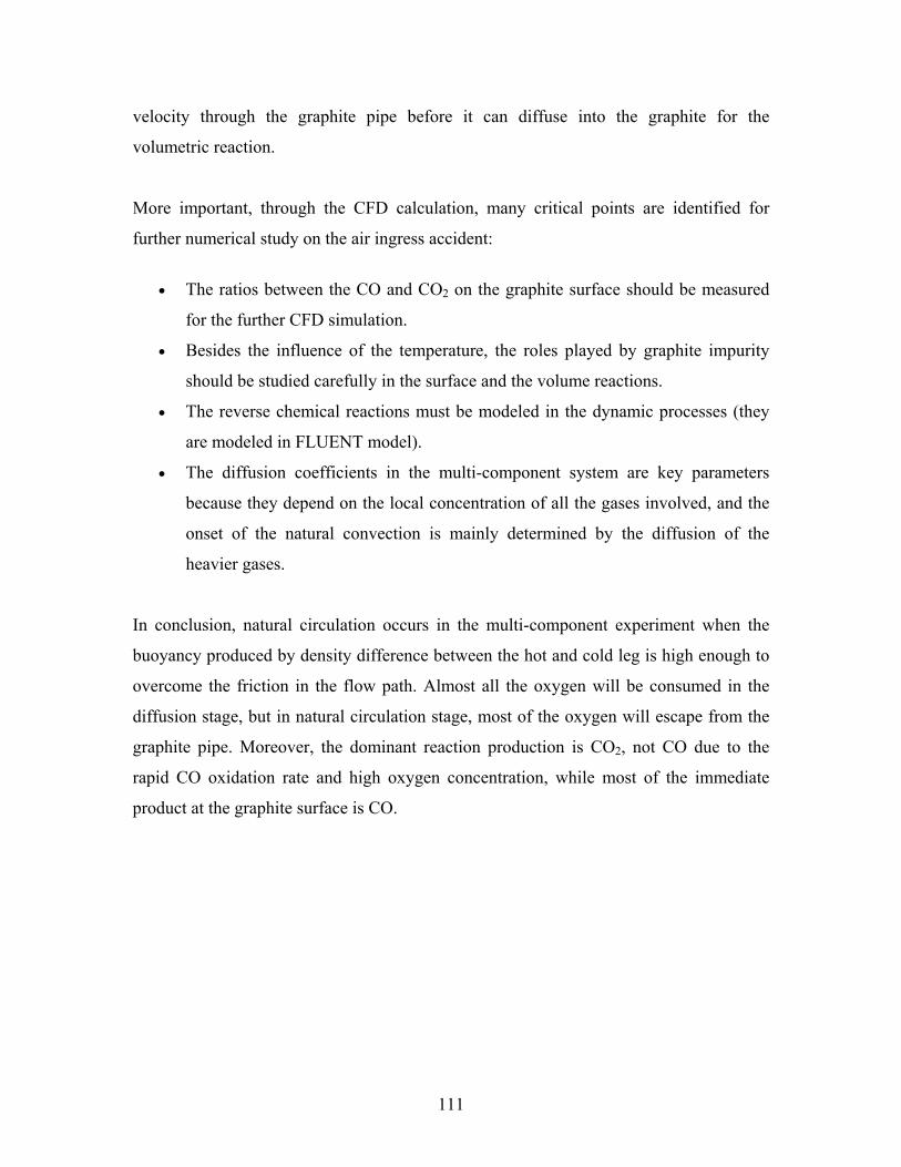
111
velocity through the graphite pipe before it can diffuse into the graphite for the
volumetric reaction.
More important, through the CFD calculation, many critical points are identified for
further numerical study on the air ingress accident:
• The ratios between the CO and CO2 on the graphite surface should be measured
for the further CFD simulation.
• Besides the influence of the temperature, the roles played by graphite impurity
should be studied carefully in the surface and the volume reactions.
• The reverse chemical reactions must be modeled in the dynamic processes (they
are modeled in FLUENT model).
• The diffusion coefficients in the multi-component system are key parameters
because they depend on the local concentration of all the gases involved, and the
onset of the natural convection is mainly determined by the diffusion of the
heavier gases.
In conclusion, natural circulation occurs in the multi-component experiment when the
buoyancy produced by density difference between the hot and cold leg is high enough to
overcome the friction in the flow path. Almost all the oxygen will be consumed in the
diffusion stage, but in natural circulation stage, most of the oxygen will escape from the
graphite pipe. Moreover, the dominant reaction production is CO2, not CO due to the
rapid CO oxidation rate and high oxygen concentration, while most of the immediate
product at the graphite surface is CO.
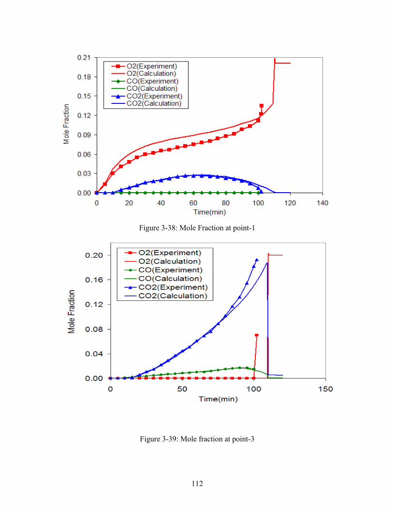
112
Figure 3-38: Mole Fraction at point-1
Figure 3-39: Mole fraction at point-3
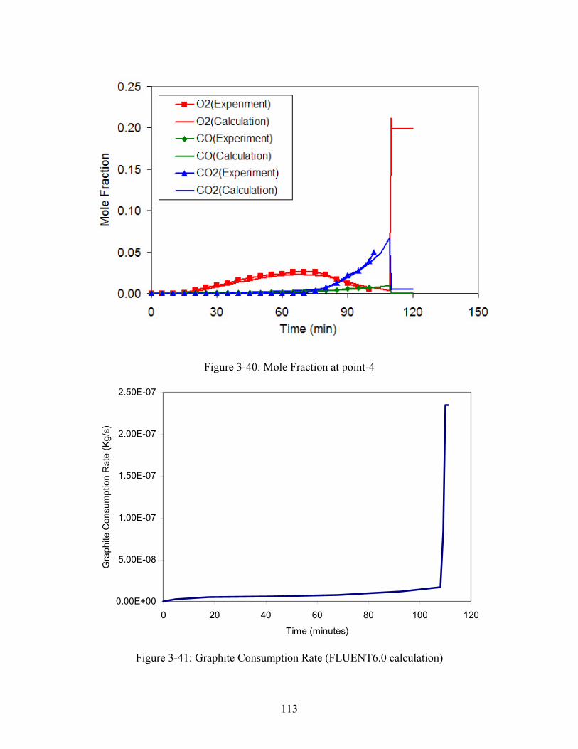
113
Figure 3-40: Mole Fraction at point-4
0.00E+00
5.00E-08
1.00E-07
1.50E-07
2.00E-07
2.50E-07
0 20 40 60 80 100 120
Time (minutes)
Gra
phite
Con
sum
ptio
n R
ate
(Kg/
s)
Figure 3-41: Graphite Consumption Rate (FLUENT6.0 calculation)
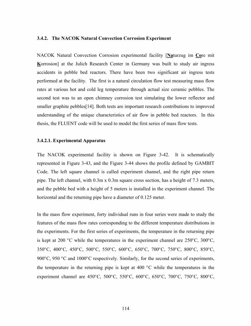
114
3.4.2. The NACOK Natural Convection Corrosion Experiment
NACOK Natural Convection Corrosion experimental facility [Naturzug im Core mit
Korrosion] at the Julich Research Center in Germany was built to study air ingress
accidents in pebble bed reactors. There have been two significant air ingress tests
performed at the facility. The first is a natural circulation flow test measuring mass flow
rates at various hot and cold leg temperature through actual size ceramic pebbles. The
second test was to an open chimney corrosion test simulating the lower reflector and
smaller graphite pebbles[14]. Both tests are important research contributions to improved
understanding of the unique characteristics of air flow in pebble bed reactors. In this
thesis, the FLUENT code will be used to model the first series of mass flow tests.
3.4.2.1. Experimental Apparatus
The NACOK experimental facility is shown on Figure 3-42. It is schematically
represented in Figure 3-43, and the Figure 3-44 shows the profile defined by GAMBIT
Code. The left square channel is called experiment channel, and the right pipe return
pipe. The left channel, with 0.3m x 0.3m square cross section, has a height of 7.3 meters,
and the pebble bed with a height of 5 meters is installed in the experiment channel. The
horizontal and the returning pipe have a diameter of 0.125 meter.
In the mass flow experiment, forty individual runs in four series were made to study the
features of the mass flow rates corresponding to the different temperature distributions in
the experiments. For the first series of experiments, the temperature in the returning pipe
is kept at 200 °C while the temperatures in the experiment channel are 250°C, 300°C,
350°C, 400°C, 450°C, 500°C, 550°C, 600°C, 650°C, 700°C, 750°C, 800°C, 850°C,
900°C, 950 °C and 1000°C respectively. Similarly, for the second series of experiments,
the temperature in the returning pipe is kept at 400 °C while the temperatures in the
experiment channel are 450°C, 500°C, 550°C, 600°C, 650°C, 700°C, 750°C, 800°C,
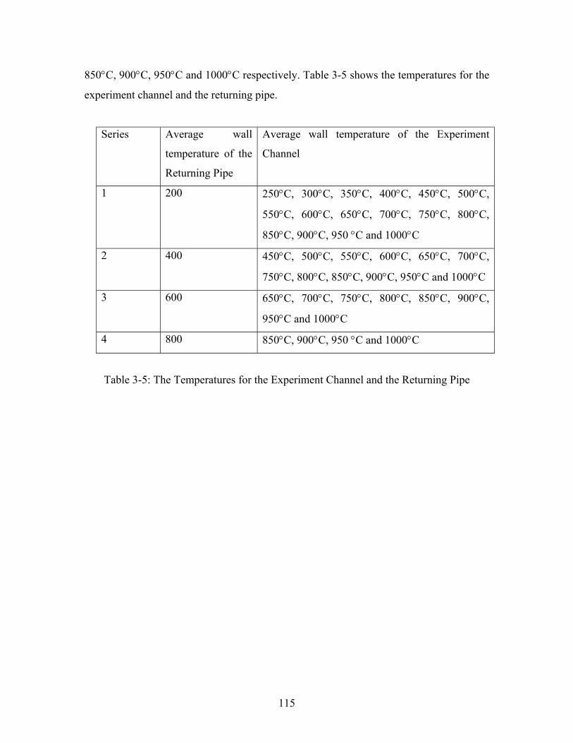
115
850°C, 900°C, 950°C and 1000°C respectively. Table 3-5 shows the temperatures for the
experiment channel and the returning pipe.
Series Average wall
temperature of the
Returning Pipe
Average wall temperature of the Experiment
Channel
1 200 250°C, 300°C, 350°C, 400°C, 450°C, 500°C,
550°C, 600°C, 650°C, 700°C, 750°C, 800°C,
850°C, 900°C, 950 °C and 1000°C
2 400 450°C, 500°C, 550°C, 600°C, 650°C, 700°C,
750°C, 800°C, 850°C, 900°C, 950°C and 1000°C
3 600 650°C, 700°C, 750°C, 800°C, 850°C, 900°C,
950°C and 1000°C
4 800 850°C, 900°C, 950 °C and 1000°C
Table 3-5: The Temperatures for the Experiment Channel and the Returning Pipe
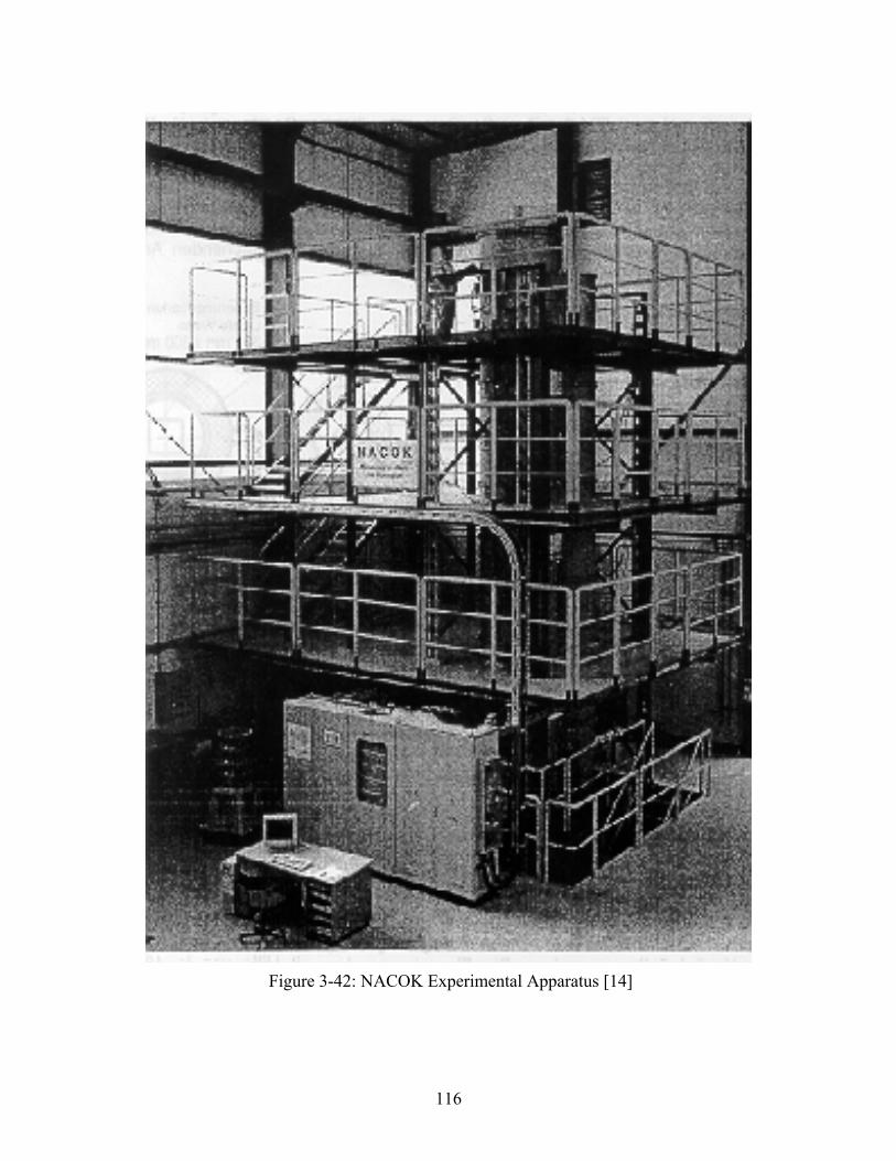
116
Figure 3-42: NACOK Experimental Apparatus [14]
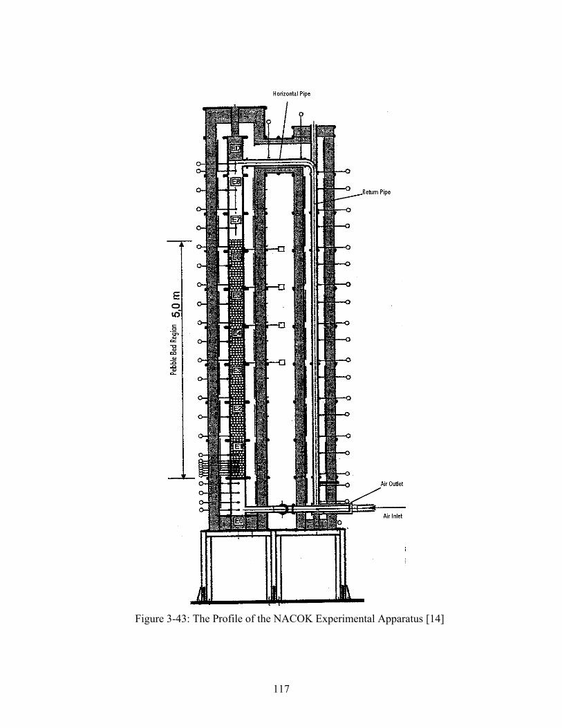
117
Figure 3-43: The Profile of the NACOK Experimental Apparatus [14]
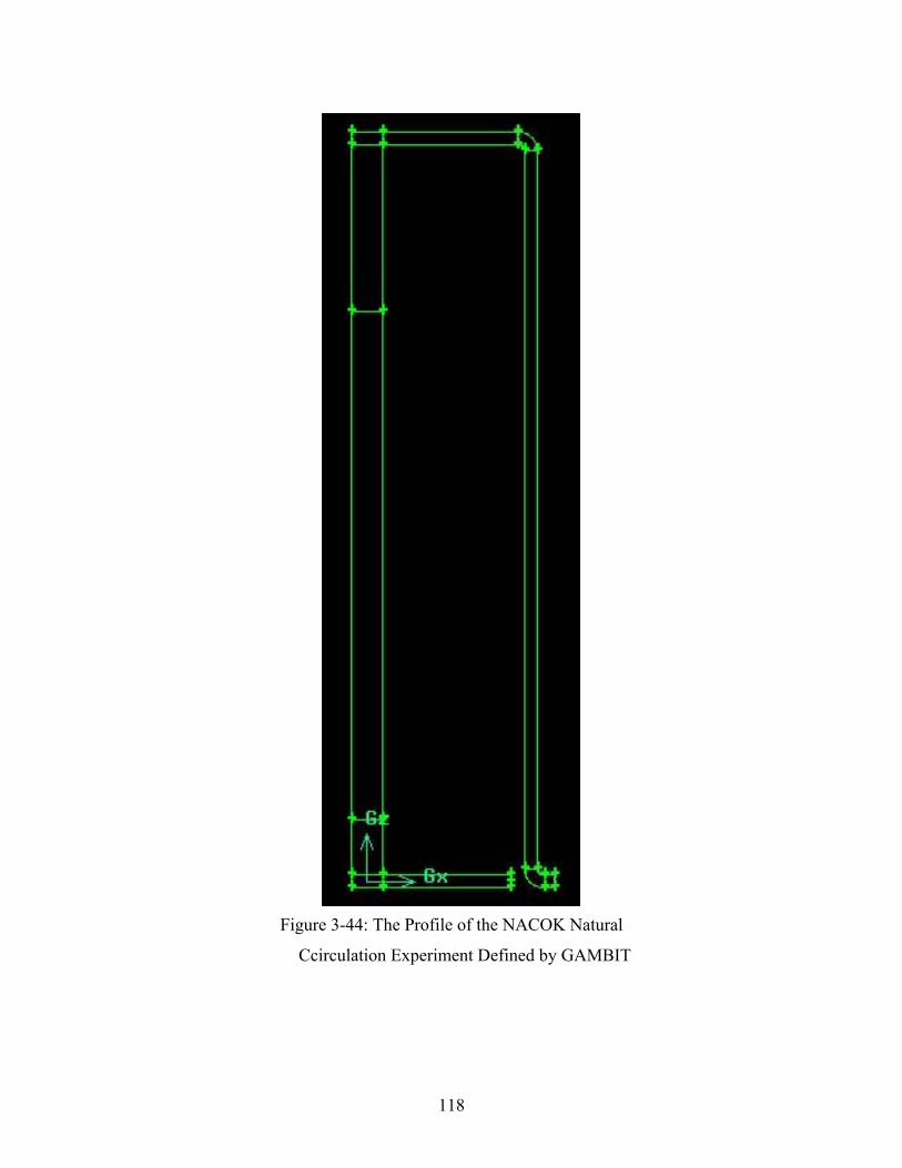
118
Figure 3-44: The Profile of the NACOK Natural
Ccirculation Experiment Defined by GAMBIT
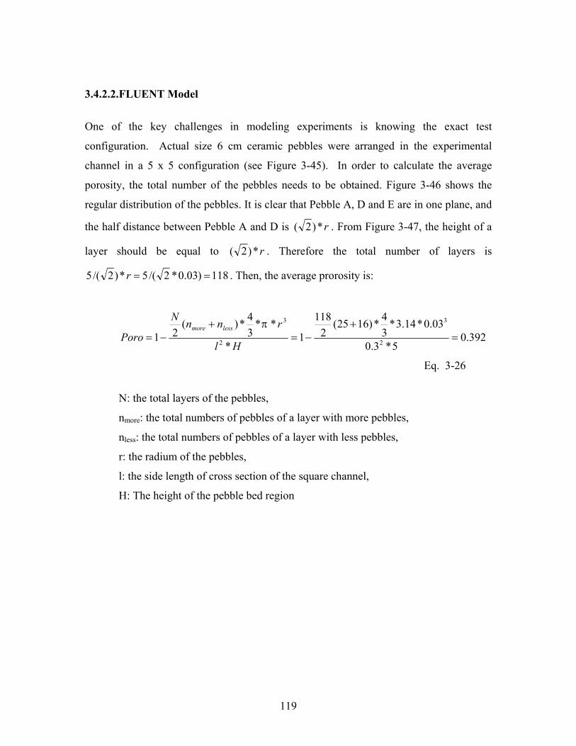
119
3.4.2.2. FLUENT Model
One of the key challenges in modeling experiments is knowing the exact test
configuration. Actual size 6 cm ceramic pebbles were arranged in the experimental
channel in a 5 x 5 configuration (see Figure 3-45). In order to calculate the average
porosity, the total number of the pebbles needs to be obtained. Figure 3-46 shows the
regular distribution of the pebbles. It is clear that Pebble A, D and E are in one plane, and
the half distance between Pebble A and D is r*)2( . From Figure 3-47, the height of a
layer should be equal to r*)2( . Therefore the total number of layers is
118)03.0*2/(5*)2/(5 ==r . Then, the average prorosity is:
392.05*3.0
03.0*14.3*34*)1625(
2118
1*
**34*)(
21 2
3
2
3
=+
−=+
−=Hl
rnnN
Porolessmore π
Eq. 3-26
N: the total layers of the pebbles,
nmore: the total numbers of pebbles of a layer with more pebbles,
nless: the total numbers of pebbles of a layer with less pebbles,
r: the radium of the pebbles,
l: the side length of cross section of the square channel,
H: The height of the pebble bed region
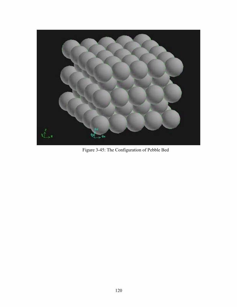
120
Figure 3-45: The Configuration of Pebble Bed
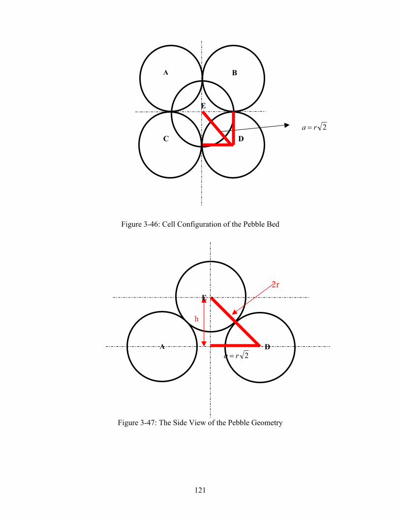
121
Figure 3-46: Cell Configuration of the Pebble Bed
Figure 3-47: The Side View of the Pebble Geometry
A
E
DC
B
2ra =
h
2ra =
2rE
A D
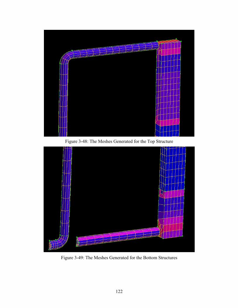
122
Figure 3-48: The Meshes Generated for the Top Structure
Figure 3-49: The Meshes Generated for the Bottom Structures
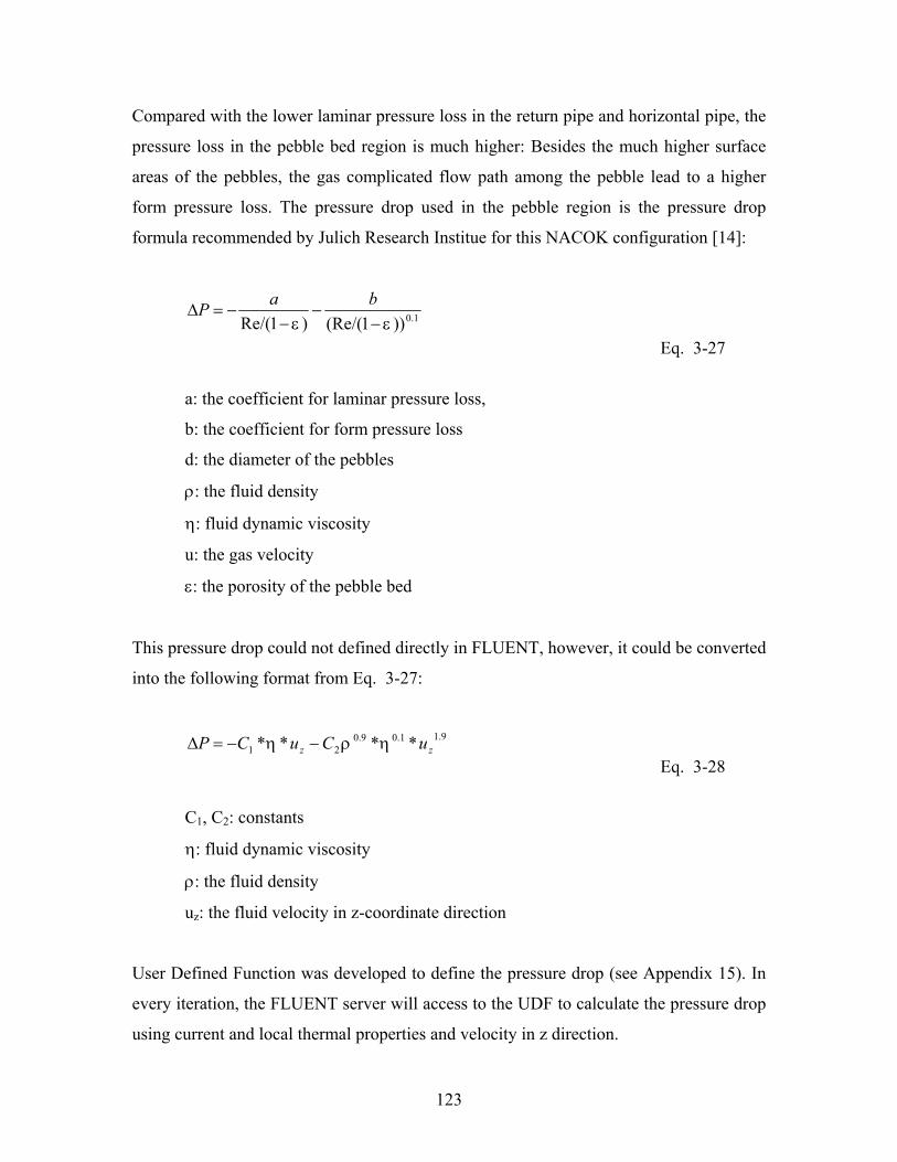
123
Compared with the lower laminar pressure loss in the return pipe and horizontal pipe, the
pressure loss in the pebble bed region is much higher: Besides the much higher surface
areas of the pebbles, the gas complicated flow path among the pebble lead to a higher
form pressure loss. The pressure drop used in the pebble region is the pressure drop
formula recommended by Julich Research Institue for this NACOK configuration [14]:
1.0))1(Re/()1Re/( εε −−
−−=∆
baP
Eq. 3-27
a: the coefficient for laminar pressure loss,
b: the coefficient for form pressure loss
d: the diameter of the pebbles
ρ: the fluid density
η: fluid dynamic viscosity
u: the gas velocity
ε: the porosity of the pebble bed
This pressure drop could not defined directly in FLUENT, however, it could be converted
into the following format from Eq. 3-27:
9.11.09.021 **** zz uCuCP ηρη −−=∆
Eq. 3-28
C1, C2: constants
η: fluid dynamic viscosity
ρ: the fluid density
uz: the fluid velocity in z-coordinate direction
User Defined Function was developed to define the pressure drop (see Appendix 15). In
every iteration, the FLUENT server will access to the UDF to calculate the pressure drop
using current and local thermal properties and velocity in z direction.
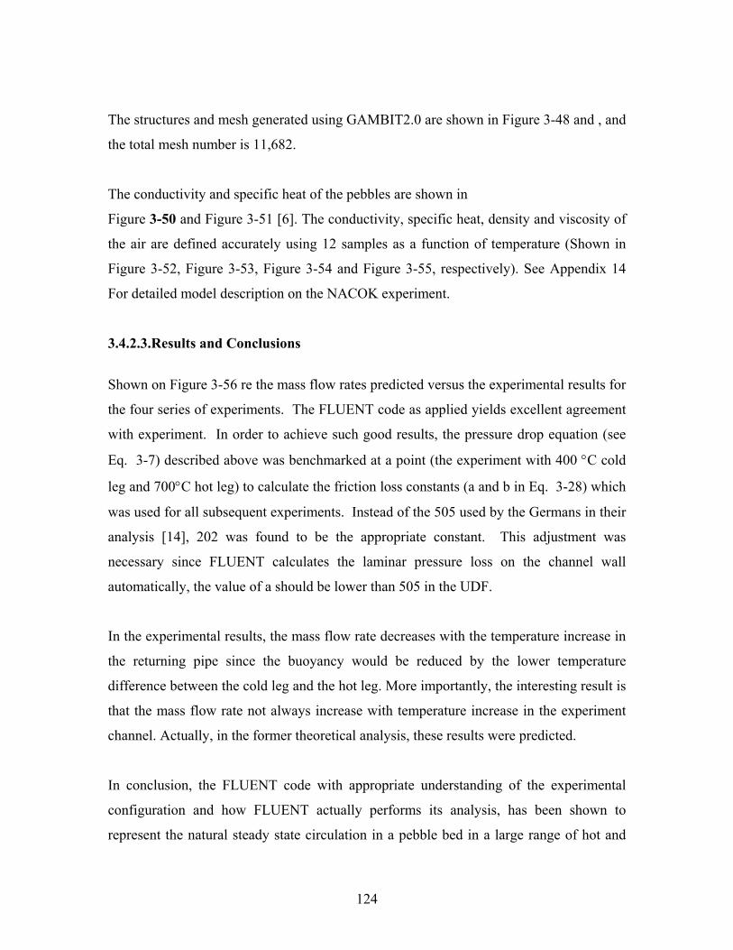
124
The structures and mesh generated using GAMBIT2.0 are shown in Figure 3-48 and , and
the total mesh number is 11,682.
The conductivity and specific heat of the pebbles are shown in
Figure 3-50 and Figure 3-51 [6]. The conductivity, specific heat, density and viscosity of
the air are defined accurately using 12 samples as a function of temperature (Shown in
Figure 3-52, Figure 3-53, Figure 3-54 and Figure 3-55, respectively). See Appendix 14
For detailed model description on the NACOK experiment.
3.4.2.3. Results and Conclusions
Shown on Figure 3-56 re the mass flow rates predicted versus the experimental results for
the four series of experiments. The FLUENT code as applied yields excellent agreement
with experiment. In order to achieve such good results, the pressure drop equation (see
Eq. 3-7) described above was benchmarked at a point (the experiment with 400 °C cold
leg and 700°C hot leg) to calculate the friction loss constants (a and b in Eq. 3-28) which
was used for all subsequent experiments. Instead of the 505 used by the Germans in their
analysis [14], 202 was found to be the appropriate constant. This adjustment was
necessary since FLUENT calculates the laminar pressure loss on the channel wall
automatically, the value of a should be lower than 505 in the UDF.
In the experimental results, the mass flow rate decreases with the temperature increase in
the returning pipe since the buoyancy would be reduced by the lower temperature
difference between the cold leg and the hot leg. More importantly, the interesting result is
that the mass flow rate not always increase with temperature increase in the experiment
channel. Actually, in the former theoretical analysis, these results were predicted.
In conclusion, the FLUENT code with appropriate understanding of the experimental
configuration and how FLUENT actually performs its analysis, has been shown to
represent the natural steady state circulation in a pebble bed in a large range of hot and
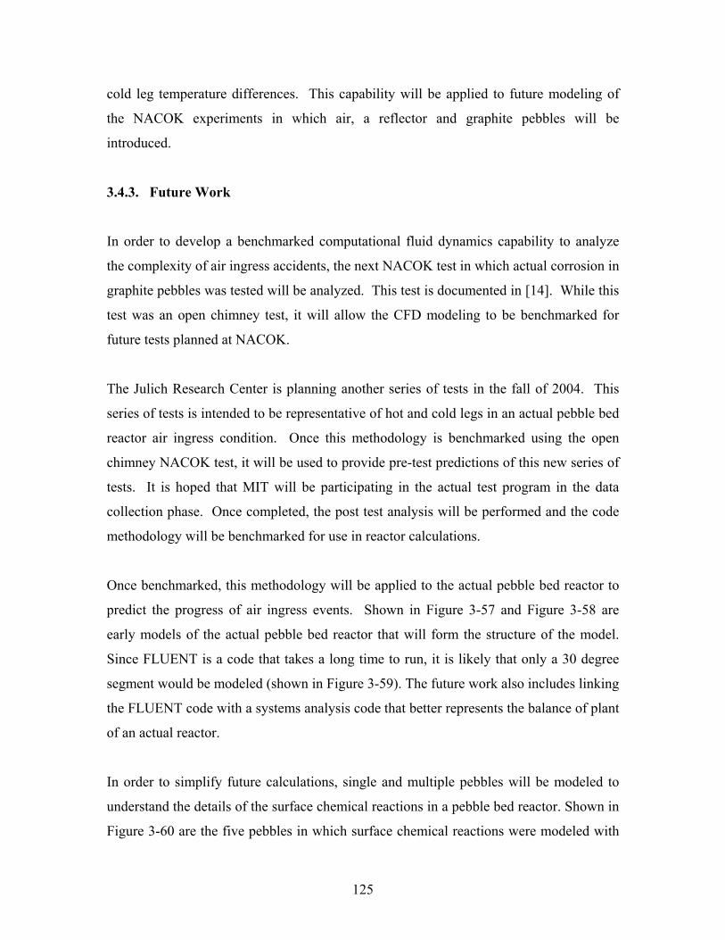
125
cold leg temperature differences. This capability will be applied to future modeling of
the NACOK experiments in which air, a reflector and graphite pebbles will be
introduced.
3.4.3. Future Work
In order to develop a benchmarked computational fluid dynamics capability to analyze
the complexity of air ingress accidents, the next NACOK test in which actual corrosion in
graphite pebbles was tested will be analyzed. This test is documented in [14]. While this
test was an open chimney test, it will allow the CFD modeling to be benchmarked for
future tests planned at NACOK.
The Julich Research Center is planning another series of tests in the fall of 2004. This
series of tests is intended to be representative of hot and cold legs in an actual pebble bed
reactor air ingress condition. Once this methodology is benchmarked using the open
chimney NACOK test, it will be used to provide pre-test predictions of this new series of
tests. It is hoped that MIT will be participating in the actual test program in the data
collection phase. Once completed, the post test analysis will be performed and the code
methodology will be benchmarked for use in reactor calculations.
Once benchmarked, this methodology will be applied to the actual pebble bed reactor to
predict the progress of air ingress events. Shown in Figure 3-57 and Figure 3-58 are
early models of the actual pebble bed reactor that will form the structure of the model.
Since FLUENT is a code that takes a long time to run, it is likely that only a 30 degree
segment would be modeled (shown in Figure 3-59). The future work also includes linking
the FLUENT code with a systems analysis code that better represents the balance of plant
of an actual reactor.
In order to simplify future calculations, single and multiple pebbles will be modeled to
understand the details of the surface chemical reactions in a pebble bed reactor. Shown in
Figure 3-60 are the five pebbles in which surface chemical reactions were modeled with
126
air flowing around the pebbles. These smaller models will be used to provide a better
understanding of the pebble dynamics that would be used to confirm the more simplistic
porosity assumption used in FLUENT. Should this be successful, tens or hundreds of
pebbles would be modeled in detail to generate the desired database, such as regional
chemical reaction rates in the pebble bed. This database obtained will be used in the real
PBMR calculation, in which the pebble bed would be modeled as porous media and a
bottom reflector would be analyzed in detail since it is expected that most of the chemical
reactions occur in this area.
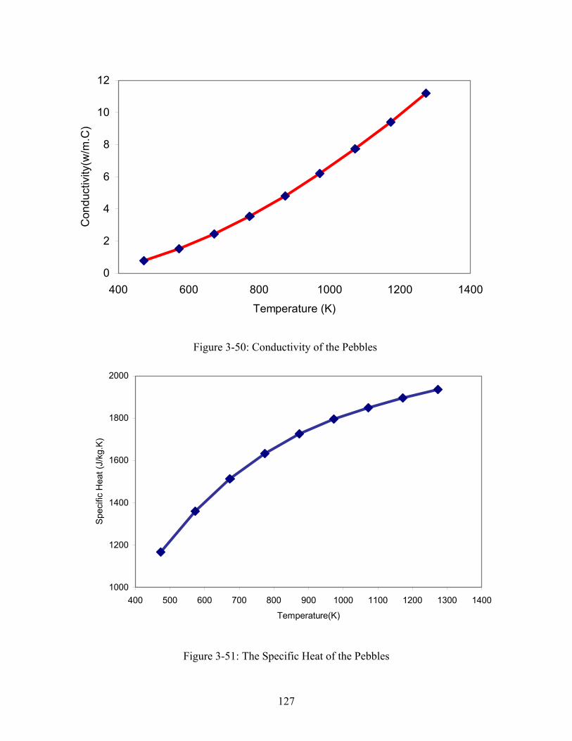
127
Figure 3-50: Conductivity of the Pebbles
Figure 3-51: The Specific Heat of the Pebbles
1000
1200
1400
1600
1800
2000
400 500 600 700 800 900 1000 1100 1200 1300 1400
Temperature(K)
Spec
ific
Hea
t (J/
kg.K
)
0
2
4
6
8
10
12
400 600 800 1000 1200 1400Temperature (K)
Con
duct
ivity
(w/m
.C)
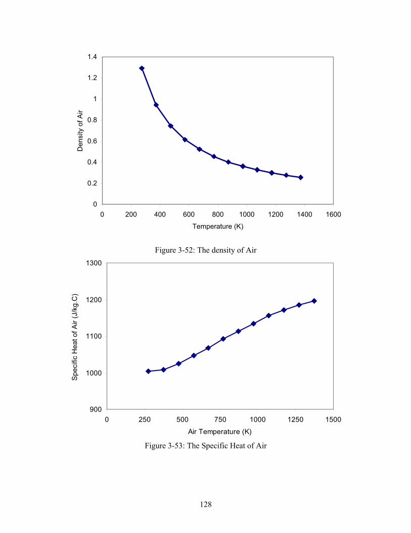
128
0
0.2
0.4
0.6
0.8
1
1.2
1.4
0 200 400 600 800 1000 1200 1400 1600
Temperature (K)
Den
sity
of A
ir
Figure 3-52: The density of Air
900
1000
1100
1200
1300
0 250 500 750 1000 1250 1500
Air Temperature (K)
Spec
ific
Hea
t of A
ir (J
/kg.
C)
Figure 3-53: The Specific Heat of Air
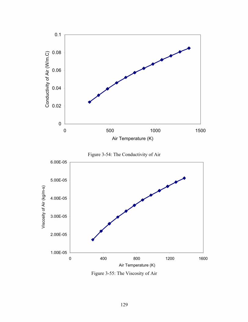
129
0
0.02
0.04
0.06
0.08
0.1
0 500 1000 1500Air Temperature (K)
Con
duct
ivity
of A
ir (W
/m.C
)
Figure 3-54: The Conductivity of Air
1.00E-05
2.00E-05
3.00E-05
4.00E-05
5.00E-05
6.00E-05
0 400 800 1200 1600Air Temperature (K)
Visc
osity
of A
ir (k
g/m
-s)
Figure 3-55: The Viscosity of Air
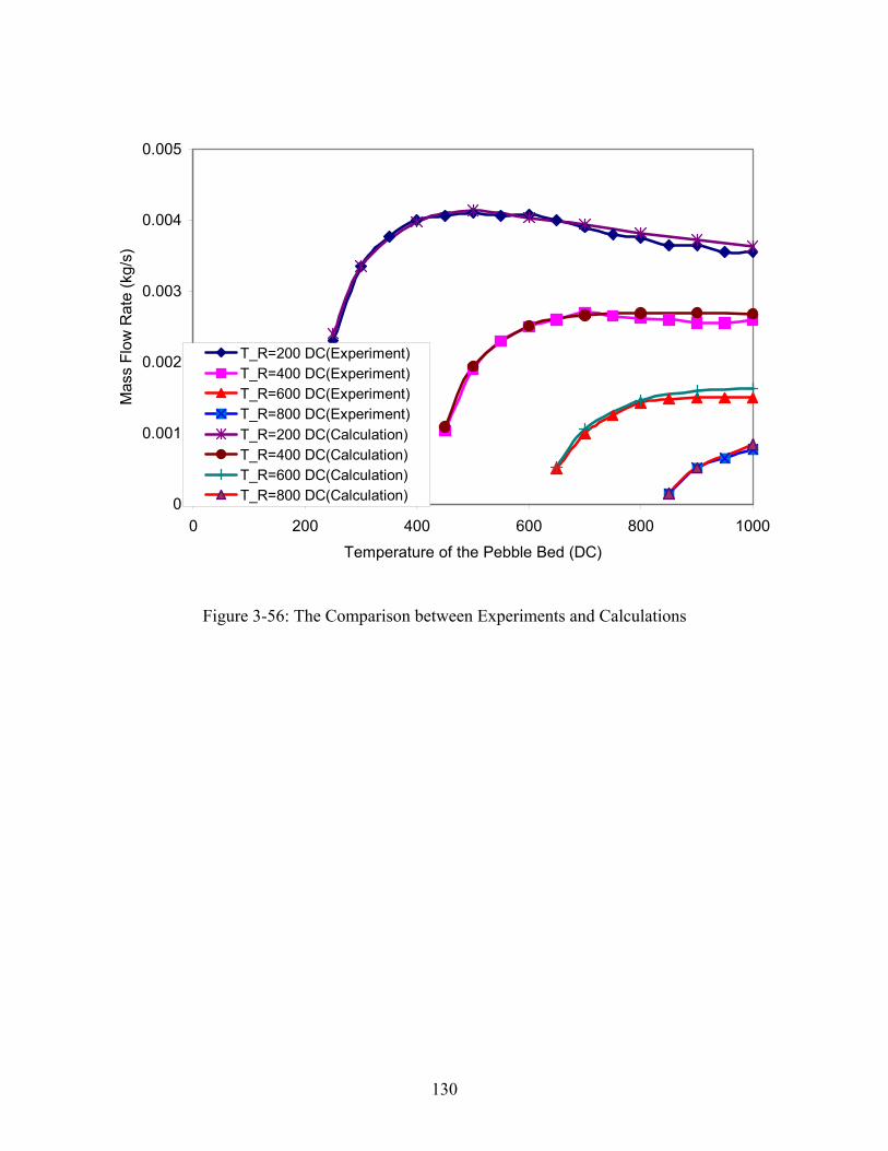
130
Figure 3-56: The Comparison between Experiments and Calculations
0
0.001
0.002
0.003
0.004
0.005
0 200 400 600 800 1000Temperature of the Pebble Bed (DC)
Mas
s Fl
ow R
ate
(kg/
s)
T_R=200 DC(Experiment)T_R=400 DC(Experiment)T_R=600 DC(Experiment)T_R=800 DC(Experiment)T_R=200 DC(Calculation)T_R=400 DC(Calculation)T_R=600 DC(Calculation)T_R=800 DC(Calculation)
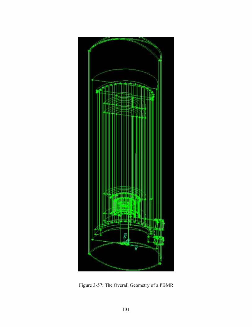
131
Figure 3-57: The Overall Geometry of a PBMR
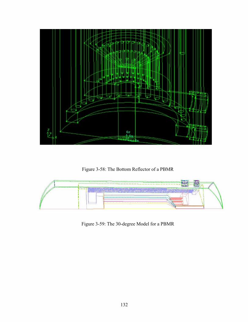
132
Figure 3-58: The Bottom Reflector of a PBMR
Figure 3-59: The 30-degree Model for a PBMR
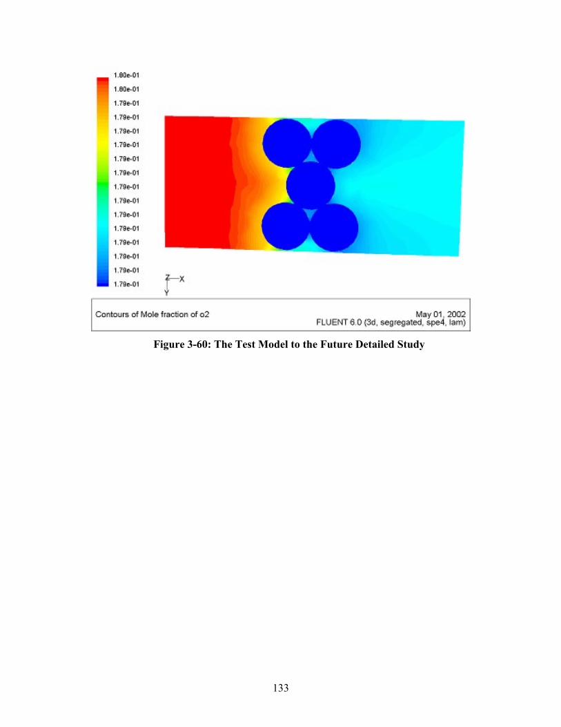
133
Figure 3-60: The Test Model to the Future Detailed Study
134
4. Conclusions and Future Work
The objective of this thesis was to investigate the key safety features of the pebble bed
reactor under challenging conditions. The first part of the thesis explored the “no
meltdown” claim of the proponents of the technology without the use of any active
emergency core cooling systems after a loss of coolant accident. Using a conservative
HEATING-7 analysis which modeled the PBMR core, reactor vessel, reactor cavity,
concrete and soil ultimate heat sink in which no convective heat transfer as assumed, it
was shown that the peak fuel temperature was approximately 1642 C approximately 92
hours after the initial loss of coolant which is about 1000 °C below the UO2 fuel melting
temperature, ~2700 °C [27]. Sensitivity studies also showed that the peak fuel
temperature was insensitive to many parameters, the most important of which was
believed to be the emissivity of the reactor vessel.
It was established that although the fuel would not melt, the temperature of the reactor
vessel and the reactor cavity concrete exceeded design limits. A separate study by
Professor Hee Cheon No using new code developed for this application (PEB-SIM)
confirmed the HEATING-7 peak temperature results without convection cooling in the
reactor cavity. His analysis was extended to perform a sensitivity study to determine how
much air would have to be circulated in the reactor cavity to bring the temperatures of the
reactor vessel and reactor cavity within design limits. This study showed that
approximately 6 m/s of air flow would be required. The study also showed that the peak
fuel temperature was unaffected by the reactor cavity cooling system. The conclusion
was that although the core will not melt even under these very conservative conditions by
a large margin, some form of reactor cavity cooling system will be required to keep the
reactor vessel and reactor cavity concrete within design limits. Future work in this area
will be the design of a passive reactor cavity core cooling system based on the design
inferences identified in this study.
135
The second part of this thesis was to develop a better understanding of the details of air
ingress accidents in pebble bed and prismatic reactors. A theoretical study of an open
cylinder of pebbles to better understand the key processes involved in air ingress was
performed using the previous results from the LOCA analysis as initial conditions. The
HEATING-7 model with side calculations to model the buoyancy and resistance to flow
in a pebble was used to predict the peak fuel temperatures and air ingress velocity. The
results of this simple analysis showed that that heat source contribution from the
chemical reaction was relatively low and confined to the lower reflector region. The
peak temperature increase from the non-chemical LOCA analysis was about 21 °C (a
maximum of 1663 °C at 92 hours). Dr. No’s analysis using PEB-SIM with chemical
reactions showed similar results (peak temperature of 1617°C at 80 hours). The other
interesting result was that the air ingress velocity decreased after about 350 °C. This
negative feedback could be a significant factor in air ingress accidents in real reactors
since the average post LOCA temperature in the reactor is on the order of 1300 °C.
Using these fundamental insights, attention was then focused on developing a
benchmarked computational fluid dynamics modeling capability for air ingress events.
Two series of tests were used to benchmark the CFD code selected for this analysis –
FLUENT 6.0. The first series of tests were performed at the Japan Atomic Energy
Research Institute (JAERI). These tests were aimed at understanding the fundamental
processes of air ingress accidents in separate effects tests. There are initial diffusion,
natural circulation and the chemical reactions with heated graphite in a prismatic reactor
configuration. The FLUENT model and methodology developed was able to predict each
of these tests quite well.
The second experimental benchmark was the Julich Research Center test performed at the
NACOK facility. This series of tests was to model natural circulation in a pebble bed
reactor under varying hot and cold leg temperatures to assess air mass flow rate. The
FLUENT methodology developed was able to predict the mass flow rates for the 40
experiments with very good results. This work will be used to benchmark the NACOK
chemical corrosion tests in the future. A outline for the work plan for continuation of this

136
work has been prepared for development of a benchmarked CFD capability to analyze the
details of air ingress accidents for real reactors.
137
Reference:
[1] Moormann, R., November 1983. “Graphite oxidation phenomena during massive air
ingress accidents in nuclear high temperature gas cooled reactors with pebble bed core,”
Berichte der Bunsengesellschaft fuer Physikalische Chemie. Ber. Bunsenges. Phys.
Chem. V. 87(11) p. 1086-1090. CODEN: BBPCA.
[2] Kadak, A.C., Ballinger, R.G., “Modular Pebble Bed Reactor Project, Fourth Annual
Report” MIT-ANP-PR-094, December 2002.
[3] Lyman, Edwin S. “The Pebble-Bed Modular Reactor (PBMR): Safety Issues”,
Forumon, Physics Y society of the of The American Physical Society, October 2001.
[4] Childs, K. W., February 1993, “HEATING 7.2 USER’S MANUAL”, Oak Ridge
National Laboratory ORNL/TM-12262.
[5] Lebenhaft, J., “PBMR Temperature Map in the normal operation calculated by
VSOP”, August, 2000.
[6] Yan, Xinglong, June, 1990, “Dynamic Analysis and Control System Design for an
Advanced Nuclear Gas Turbine Power Plant”. MIT Ph.D thesis.
[7] Yang, S., “Heat Transfer”, second edition, Beijing, 1989.
[8] Rohsenow, M. W. and P. J. Hartnett, 1973. Handbook of Heat Transfer.
[9] Wichner, R.P., April 1999, “Potential Damage to Gas-Cooled Graphite Reactors Due
to Severe Accidents”, Oak Ridge National Laboratory.
138
[10] No, H. C., 2001. “PBR System Simulation Code for Depressurization Accident
Analysis in a Modular Pebble Bed Reactor,” Massachusetts Institute of Technology.
[11] Hishida, M., and T. Takeda, 1991. “Study on air ingress during an early stage of
a primary-pipe rupture accident of a high-temperature gas-cooled reactor,” Nuclear
Engineering and Design, 126, 175-187.
[12] Takeda, T., and M. Hishida, 1992. “Studies on diffusion and natural convection
of two-component gases,” Nuclear Engineering and Design, 135, 341-354.
[13] Takeda T. and Hishida, M., “Studies on molecular diffusion and natural
convection in a multicomponent gas system,” Int. J. Heat Mass Transfer”, Vol. 39, No. 3,
pp. 527-536, 1996.
[14] Kuhlmann, M. B., “Experiments to investigate flow transfer and graphite
corrosion in case of air ingress accidents in a high-temperature reactor”. 1999.
[15] Hohn. H., “NACOK, Natural Convection in Core”. Forchungszentrum Julich,
Auslegung, Ergebnisse.
[16] Katscher, W.More, Man, R. Moorland, Roes, J., “Experimental Results of
corrosion investigations.”
[17] FLUENT Inc. 2002, “FLUENT 6.0 User's Guide”
[18] FLUENT Inc. 2002, “GAMBIT 2.0 User's Guide”
[19] Rehm, W., W. John, and K. Verfondern, 1988. “Present Results and Further
Developments on Safety Analysis of Small and Medium-Sized HTRs for Core Heat-Up
Accidents,” Nuclear Engineering and Design 109, pp. 281-287.
139
[20] Tang, Chunhe, Guan, Jie, “Improvement in oxidation resistance of the nuclear
graphite by reaction-coated SiC coating”, Institute of Nuclear Energy Technology,
Tsinghua University.
[21] Oh, C., Merrill, B., Moore, R., and D. Petti, January, 2001, “Oxidation Model for
a MPBR Graphite Pebble,” Idaho National Engineering & Environmental Laboratory.
[22] Liu, G. N-K., August 1973. “High temperature oxidation of graphite by a
dissociated oxygen beam,” Master thesis of MIT.
[23] Fenech, Henri, “Heat Transfer and Fluid Flow in Nuclear Systems”, Pergamon
Press, 1980, P382-401.
[24] O’Brien, M. H., B. J. Merrill, and S. N. Ugaki, September 1988. “Combustion
Testing and Thermal Modeling of Proposed CIT Graphite Tile Material,” EGG-FSP-
8255, Idaho National Engineering Laboratory.
[25] Gao, Z., Li, B., Wang, C., Jiang, Z., Institute of Nuclear Energy Technology,
Tsinghua University, “Transient Analysis of Air Ingress From Broken Pipe into the HTR-
10 Reactor Pressure Vessel”, Beijing, China.
[26] Bird, R. B., W. E. Stewart, and E. N. Lightfoot, 1960, Transport Phenomena, John
Wiley and Sons, New York, p. 269.
[27] Solomon, A., “Enhanced Thermal Conductivity of Oxide Fuels”, Purdue
University, Nuclear Energy Research Initiative”, 2002.
[28] Bazant, Z.P, 1996. “Material Properties and Mathematical Models”, Harlow
Longman.
140
[29] Carlson, K. E., P. A. Roth, and V. H. Ransom, ATHENA Code Manual Vol. I:
Code Structure, System Models, and Solution Methods, EGG-RTH-7397, September
1986.
[30] Gauntt, R. O., R. K. Cole, S. A. Hodge, S. B. Rodriguez, R. L. Sanders, R. C.
Smith, D. S. Stuart, R. M. Summers, and M. F. Young, 1997. “MELCOR Computer
Code Manuals,” NUREG/CR-6119, Vol. 1, Rev. 1, SAND97-2397-2398.
[31] Kadak, A.C, Zhai, T., “(The Annual Report on PBMR) The Loss of Coolant
Accident with Depressurization”, July, 2001, Massachusetts Institute of Technology.
[32] Merrill, B. J., R. L. Moore, S. T. Polkinghorne, and D. A. Petti, 2000. Fusion
Engineering and Design, 51-52, 555-563.
[33] Moorman, R., and W. Katscher, 5-10 June 1988. “Examination of graphite
burning in high temperature gas cooled reactors,” Nuclear reactor severe accident
chemistry symposium, Toronto (Canada).
[34] Mosevitskij, I.S., and A. V. Djakov, 5-8 November 1990. “Problems of
investigation of HTGR fuel elements under loss-of-pressure accidents,” Specialists
meeting on behavior of gas cooled reactor fuel under accident conditions. Oak Ridge, TN
(United States).
[35] Neale, G. H., and W. K. Nader, May 1974. “Prediction of Transport Processes
Within Porous Media: Creeping Flow Relative to a Fixed Swarm of Spherical Particles,”
AIChE Journal (Vol. 20, No. 3.).
[36] Nieben, H.F., B. Stocker, O. Amoignon, Z. Gao, and J. Liu, September 30-
October 4, 1997. “Sana Experiments for Self-Acting Removal of the After-Heat in
141
Reactors with Pebble Bed Fuel and Their Interpretation,” Eighth International Topical
Meeting on Nuclear Thermal-Hydraulic. Kyoto, Japan.
[37] Nightingale, R.E., “Nuclear Graphite”, Handford Laboratories, General Electric
Company, Academic Press-1962.
[38] Ogawa, M., B. Stauch, R. Moormann, and W. Katscher, November 1985. “An
experimental investigation on mass transfer in presence of chemical reactions on a
graphite cylinder in crossflow,” Juel-Spez—336 {JuelSpez336}, p. 42.
[39] Ozisik, M. N., 1993. Heat Conduction (Second Edition).
[40] Petersen, K., H. Barthels, and G. Breitbach, 30 March 1976. “Natural convection
in the core of a pebble-bed reactor,” Reactor Meeting, Duesseldorf, F.R. Germany.
[41] Petersen, K., H. Barthels, and R. Schulten, 14 November 1976. “Natural-
convection afterheat removal from the pebble-bed HTGR,” Transactions of the American
Nuclear Society 1976 international meeting, Washington, DC.
[42] Peterson, K., K. Verfondern, H. Barthels, and J. Banaschek, 9-12 October 1980.
“Thermal hydraulics of the pebble bed high temperature reactor under accident
conditions,” ANS/ASME topical meeting on reactor thermal-hydraulics, Saratoga, NY.
[43] Rehm, W., J. Altes, and H. Barthels, 1990. “Thermodynamic Investigations of
Passive Decay Heat Removal From HTR Cores and Component Behaviour,” Nuclear
Engineering and Design 121, pp. 211-218.
[44] Rehm, W., W. John, and H. Barthels. “Comparison of Theoretical and
Experimental Studies of Afterheat Removal by Natural Convection/Circulation From an
HTR.”

142
[45] Shih, W. C. L., 1975. “Molecular Beam Studies of Graphite Oxidation.”

143
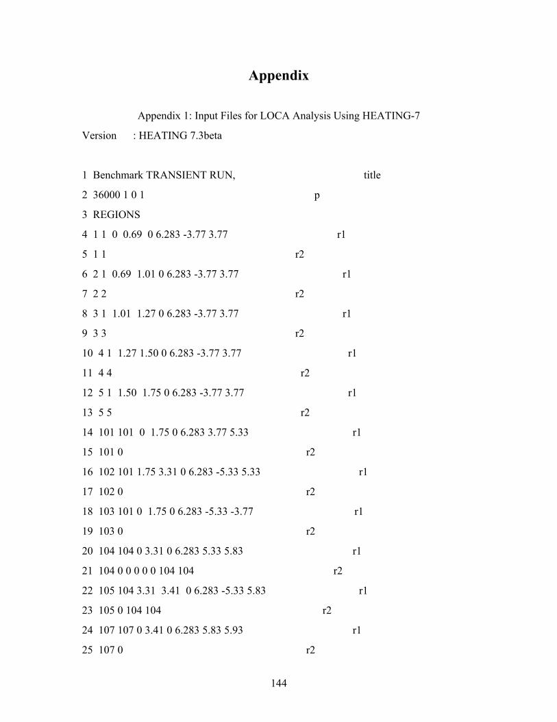
144
Appendix
Appendix 1: Input Files for LOCA Analysis Using HEATING-7
Version : HEATING 7.3beta
1 Benchmark TRANSIENT RUN, title
2 36000 1 0 1 p
3 REGIONS
4 1 1 0 0.69 0 6.283 -3.77 3.77 r1
5 1 1 r2
6 2 1 0.69 1.01 0 6.283 -3.77 3.77 r1
7 2 2 r2
8 3 1 1.01 1.27 0 6.283 -3.77 3.77 r1
9 3 3 r2
10 4 1 1.27 1.50 0 6.283 -3.77 3.77 r1
11 4 4 r2
12 5 1 1.50 1.75 0 6.283 -3.77 3.77 r1
13 5 5 r2
14 101 101 0 1.75 0 6.283 3.77 5.33 r1
15 101 0 r2
16 102 101 1.75 3.31 0 6.283 -5.33 5.33 r1
17 102 0 r2
18 103 101 0 1.75 0 6.283 -5.33 -3.77 r1
19 103 0 r2
20 104 104 0 3.31 0 6.283 5.33 5.83 r1
21 104 0 0 0 0 0 104 104 r2
22 105 104 3.31 3.41 0 6.283 -5.33 5.83 r1
23 105 0 104 104 r2
24 107 107 0 3.41 0 6.283 5.83 5.93 r1
25 107 0 r2
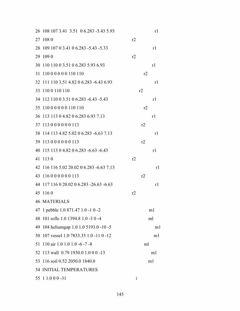
145
26 108 107 3.41 3.51 0 6.283 -5.43 5.93 r1
27 108 0 r2
28 109 107 0 3.41 0 6.283 -5.43 -5.33 r1
29 109 0 r2
30 110 110 0 3.51 0 6.283 5.93 6.93 r1
31 110 0 0 0 0 0 110 110 r2
32 111 110 3.51 4.82 0 6.283 -6.43 6.93 r1
33 110 0 110 110 r2
34 112 110 0 3.51 0 6.283 -6.43 -5.43 r1
35 110 0 0 0 0 0 110 110 r2
36 113 113 0 4.82 0 6.283 6.93 7.13 r1
37 113 0 0 0 0 0 0 113 r2
38 114 113 4.82 5.02 0 6.283 -6.63 7.13 r1
39 113 0 0 0 0 0 0 113 r2
40 115 113 0 4.82 0 6.283 -6.63 -6.43 r1
41 113 0 r2
42 116 116 5.02 20.02 0 6.283 -6.63 7.13 r1
43 116 0 0 0 0 0 0 113 r2
44 117 116 0 20.02 0 6.283 -26.63 -6.63 r1
45 116 0 r2
46 MATERIALS
47 1 pebble 1.0 871.47 1.0 -1 0 -2 m1
48 101 refle 1.0 1394.8 1.0 -3 0 -4 ml
49 104 heliumgap 1.0 1.0 5193.0 -10 -5 m1
50 107 vessel 1.0 7833.35 1.0 -11 0 -12 m1
51 110 air 1.0 1.0 1.0 -6 -7 -8 ml
52 113 wall 0.79 1930.0 1.0 0 0 -13 m1
53 116 soil 0.52 2050.0 1840.0 m1
54 INITIAL TEMPERATURES
55 1 1.0 0 0 -31 i
146
56 2 1.0 0 0 -32 i
57 3 1.0 0 0 -33 i
58 4 1.0 0 0 -34 i
59 5 1.0 0 0 -35 i
60 101 1.0 0 0 -41 i
61 102 1.0 0 0 -42 i
62 103 1.0 0 0 -43 i
63 104 279.0 i
64 105 279.0 i
65 107 279.0 i
66 108 279.0 i
67 109 279.0 i
68 110 279.0 i
69 111 279.0 i
70 112 279.0 i
71 113 50.0 i
72 114 50.0 i
73 115 50.0 i
74 116 35.0 i
75 117 35.0 i
76 HEAT GENERATION
77 1 3652700 -9 0 0 0 -51 g
78 2 3652700 -9 0 0 0 -52 g
79 3 3652700 -9 0 0 0 -53 g
80 4 3652700 -9 0 0 0 -54 g
81 5 3652700 -9 0 0 0 -55 g
82 BOUNDARY CONDITIONS
83 104 3 b1
84 0 2.349E-8 b2
85 110 3 b1

147
86 0 3.112E-8 b2
87 113 1 35 b1
88 0 3.899E-8 1.904 0.333 b2
89 XGRID
90 0.0 0.69 1.01 1.27 1.50 1.75 3.31 3.41 3.51 4.82 5.02 20.02
91 7 3 3 3 3 16 1 1 13 2 50
92 YGRID
93 0 6.283
94 2
95 ZGRID
96 -26.63 -6.63 -6.43 -5.43 -5.33 -3.77 3.77 5.33 5.83 5.93 6.93 7.13
97 50 2 10 1 16 75 16 5 1 10 2
98 TABULAR FUNCTIONS
99 1 t1
100 200.0 1.51, 400.0 3.53, 600.0 6.18, 800.0 9.39,
@ 1000.0 13.10, 1200.0 17.30, 1400.0 21.95, 1600.0 27.02,
@ 1800.0 32.51, 2000.0 38.39, 2200.0 44.66 t2
101 2 t1
102 200 1.47E+03, 400 1.90E+03, 600 2.17E+03, 800 2.32E+03,
@ 1000 2.43E+03, 1200 2.54E+03, 1400 2.72E+03,
@ 1600 3.02E+03, 1800 3.50E+03, 2000 4.22E+03, 2200 5.23E+03 t2
103 3 t1
104 20.0 8.3, 400.0 14.0, 600.0 17.0, 800.0 22.0,
@ 1000.0 24.0, 1200.0 31.0, 1400.0 37.0,
@ 1600.0 41.0, 1800.0 41.5, 2000.0 40.0,
@ 2200.0 37.0 t2
105 4 t1
106 20.0 984.7, 300.0 1330.0, 600.0 1700.0, 900.0 1870.0,
@ 1200.0 1980.0, 1500.0 2060.0, 1800.0 2110.0,
@ 2100.0 2170.0, 2400.0 2210.0 t2
148
107 5 t1
108 20.0 12.77, 100 10.031, 200 7.967, 300 6.606, 400 5.641,
@ 500 4.922, 600 4.365, 700 3.922, 800 3.560, 900 3.259,
@ 1000 3.005, 1100 2.788, 1200 2.600, 1300 2.436, 1400 2.291,
@ 1500 2.162, 1600 2.048, 1700 1.944, 1800 1.851,
@ 1900 1.766, 2000 1.689, 2100 1.618, 2200 1.553,
@ 2300 1.492, 2400 1.437, 2500 1.385, 2600 1.337,
@ 2700 1.292, 2800 1.250, 2900 1.211 t2
109 6 t1
110 0.0 0.02415, 100.0 0.03066, 200.0 0.03709,
@ 300.0 0.04326, 400.0 0.04901, 500.0 0.05481,
@ 600.0 0.06048, 700.0 0.06510, 800.0 0.07014,
@ 900.0 0.07447, 1000.0 0.07896, 1100.0 0.08295,
@ 1800.0 0.11088 t2
111 7 t1
112 20.0 1.205, 50.0 1.093, 100.0 0.946, 200.0 0.746
@ 300.0 0.615, 400.0 0.524, 500.0 0.456,
@ 600.0 0.404, 700.0 0.362, 800.0 0.329,
@ 900.0 0.301, 1000.0 0.277, 1100.0 0.257
@ 1200.0 0.239, 1800.0 0.131 t2
113 8 t1
114 20.0 1005.0, 50.0 1005.0, 100.0 1009.0,
@ 200.0 1026.0, 300.0 1047.0, 400.0 1068,
@ 500.0 1093.0, 600.0 1114.0, 700.0 1135.0
@ 800.0 1156.0, 900.0 1172.0, 1000.0 1185.0
@ 1100.0 1197.0, 1200.0 1210.0, 1800.0 1288.0 t2
115 9 t1
116 0 1.0, 1 0.042, 2 0.039, 5 0.036, 10 0.033, 80 0.032, 150 0.028,
@ 1000 0.018, 10000 8.87E-03, 100000 4.28E-03,
@ 1000000 1.89E-03, 10000000 6.55E-04, 100000000 1.11E-04 t2
149
117 10 t1
118 27 0.1564, 77 0.1692, 127 0.1872, 227 0.2206,
@ 327 0.2516, 427 0.2792, 527 0.3052, 627 0.3312,
@ 727 0.3352, 827 0.3802, 927 0.406, 1027 0.4302,
@ 1127 0.4552, 1227 0.4792, 1827 0.4792 t2
119 11 t1
120 20 44.32, 300.0 39.53, 600.0 34.39, 900.0 29.26,
@ 1200.0 24.12, 1500.0 18.99, 1800.0 13.85 t2
121 12 t1
122 20.0 492.99, 100.0 511.36, 200.0 529.54
@ 300.0 544.1, 600.0 584.2, 900.0 657.0,
@ 1200.0 811.6, 1500.0 1097.0, 1800.0 1562.0,
@ 2100.0 2256.0 2400.0 3227.0 t2
123 13 t1
124 20 970, 200 1300, 300 1200, 400 1400, 500 1520,
@ 600 1700, 700 1780, 800 1770,
@ 900 1760, 1000 1750, 1100 1740 1500 1740 t2
125 31 t1
126 -3.77 859.1, -3.6145 862.9, -3.5509 862.3, -3.412 860.8,
@ -2.7591 814.4, -2.1062 753.1, -1.4533 721.3,
@ -0.8004 694.8, -0.1475 668.8, 0.5055 640.2, 1.1584 613.1,
@ 1.8113 588.4, 2.4642 567.5, 3.1171 551.7, 3.77 542.5 t2
127 32 t1
128 -3.77 973., -3.6145 978.2, -3.5509 976.2, -3.412 977.4,
@ -2.7591 957.6, -2.1062 919.1, -1.4533 881.8,
@ -0.8004 839.7, -0.1475 793.7, 0.5055 743.7,
@ 1.1584 692.6, 1.8113 643, 2.4642 600.1,
@ 3.1171 567.7, 3.77 548.1 t2
129 33 t1
130 -3.77 968.9, -3.6145 971.8, -3.5509 977.4,
150
@ -3.412 980.5, -2.7591 966.5, -2.1062 936.8,
@ -1.4533 903.5, -0.8004 862, -0.1475 813.2, 0.5055 760,
@ 1.1584 704.7, 1.8113 650.6, 2.4642 604.1,
@ 3.1171 570.2, 3.77 549.4 t2
131 34 t1
132 -3.77 973.1, -3.412 978.5, -2.7591 957.7, -2.1062 924.5,
@ -1.4533 890.5, -0.8004 847.8, -0.1475 799.7, 0.5055 747.2,
@ 1.1584 693.1, 1.8113 640.5, 2.4642 596.5,
@ 3.1171 566.2, 3.77 548.5 t2
133 35 t1
134 -3.77 926.6, -3.412 963.3, -2.7591 942.8, -2.1062 912.5,
@ -1.4533 879.7, -0.8004 838.6, -0.1475 792.2, 0.5055 741.2,
@ 1.1584 688.3, 1.8113 636.8, 2.4642 593.8,
@ 3.1171 564.8, 3.77 548.2 t2
135 41 t1
136 3.77 549.4, 4.61 540.5, 4.74 540.1, 4.86 539.8,
@ 4.96 539.3, 5.06 537.1, 5.33 479.8 t2
137 42 t1
138 -5.33 25.1, -4.56 725.5, -4.28 726.8, -4.1469 728.2,
@ -4.0196 730.3, -3.8749 734.7, -3.7337 744.1, -3.6145 771.2,
@ -3.5509 834.3, -3.412 889.8, -2.7591 882, -2.1062 856.8,
@ -1.4533 828.8, -0.8004 793.9, -0.1475 754.5, 0.5055 711.2,
@ 1.1584 666.3, 1.8113 622.7, 2.4642 586.2, 3.1171 561.4,
@ 3.77 547.3, 4.61 539.5, 4.735 536.4, 4.86 532,
@ 4.96 529.5, 5.06 525.1, 5.33 476.4 t2
139 43 t1
140 -5.33 873.3, -3.77 973.1 t2
141 51 t1
142 -3.77 0.011126, -3.35113 0.011126, -2.51335 0.014114,
@ -1.67557 0.016232, -0.83779 0.017734, -0.00001 0.018081,
151
@ 0.83777 0.017129, 1.67555 0.014212, 2.51333 0.010295,
@ 3.35111 0.005818, 3.77 0.005818 t2
143 52 t1
144 -3.77 0.762057, -3.393 0.762057, -2.639 0.926468, -1.885 1.138509,
@ -1.131 1.308254, -0.377 1.409298, 0.377 1.402658,
@ 1.131 1.289141, 1.885 1.038878,
@ 2.639 0.728655, 3.393 0.421222, 3.77 0.421222 t2
145 53 t1
146 -3.77 1.028516, -3.42723 1.028516, -2.74178 1.252647,
@ -2.05633 1.443015, -1.37088 1.651595, -0.68543 1.800878,
@ 0.00002 1.878047, 0.68547 1.854554, 1.37092 1.704583,
@ 2.05637 1.327315, 2.74182 0.915033, 3.42727 0.541849
@ 3.77 0.541849 t2
147 54 t1
148 -3.77, 0.844293, -3.4558 0.844293, -2.82747 0.945036,
@ -2.19914 1.112876, -1.57081 1.262258, -0.94248 1.454724,
@ -0.31415 1.598541, 0.31418 1.69581, 0.94251 1.676789,
@ 1.57084 1.524377, 2.19917 1.143208, 2.8275 0.753729,
@ 3.45583 0.459489, 3.77 0.459489 t2
149 55 t1
150 -3.77 0.785065, -3.51872 0.785065, -3.01605 0.767299,
@ -2.51338 0.770856, -2.01071 0.841702, -1.50804 0.922295,
@ -1.00537 1.070319, -0.5027 1.241168, 0 1.432057,
@ 0.50264 1.598229, 1.00531 1.70759, 1.50798 1.712877,
@ 2.01065 1.563896, 2.51332 1.156261, 3.01599 0.711366,
@ 3.51867 0.426499, 3.77 0.426499 t2
151 PRINTOUT TIMES
152 1800 3600 7200 10800 18000 36000 43200 50400 57600 64800
@ 72000 79200 158400 201600 244800 288000 331200 360000
@ 374400 604800 1296000 2592000 432000 5184000 5616000
152
@ 6048000 6480000 6912000 7344000 7776000 O
153 TRANSIENT
154 2 7776000 tr
155 0.7 10E-3 1 10E-3 tr2
156 0 1.1 tr3
157 %
***************************** CASE DESCRIPTION
******************************
Benchmark TRANSIENT RUN, t
********************** SUMMARY OF PARAMETER CARD DATA
***********************
Maximum cpu time - 36000.00 seconds
Geometry type number - 1 (rtz )
Initial time - 0.0000000E+00
This is a restart of previous case - No
Read node-to-node connector data file - No
Redirect or suppress convergence information - Yes (Suppress)
Output selected information during calculations - No
Write surface heat fluxes to plot file - No
Units used in problem solution and in material properties library
Problem Library
Time - s s
Length - m cm
Mass - kg g
Energy - J cal
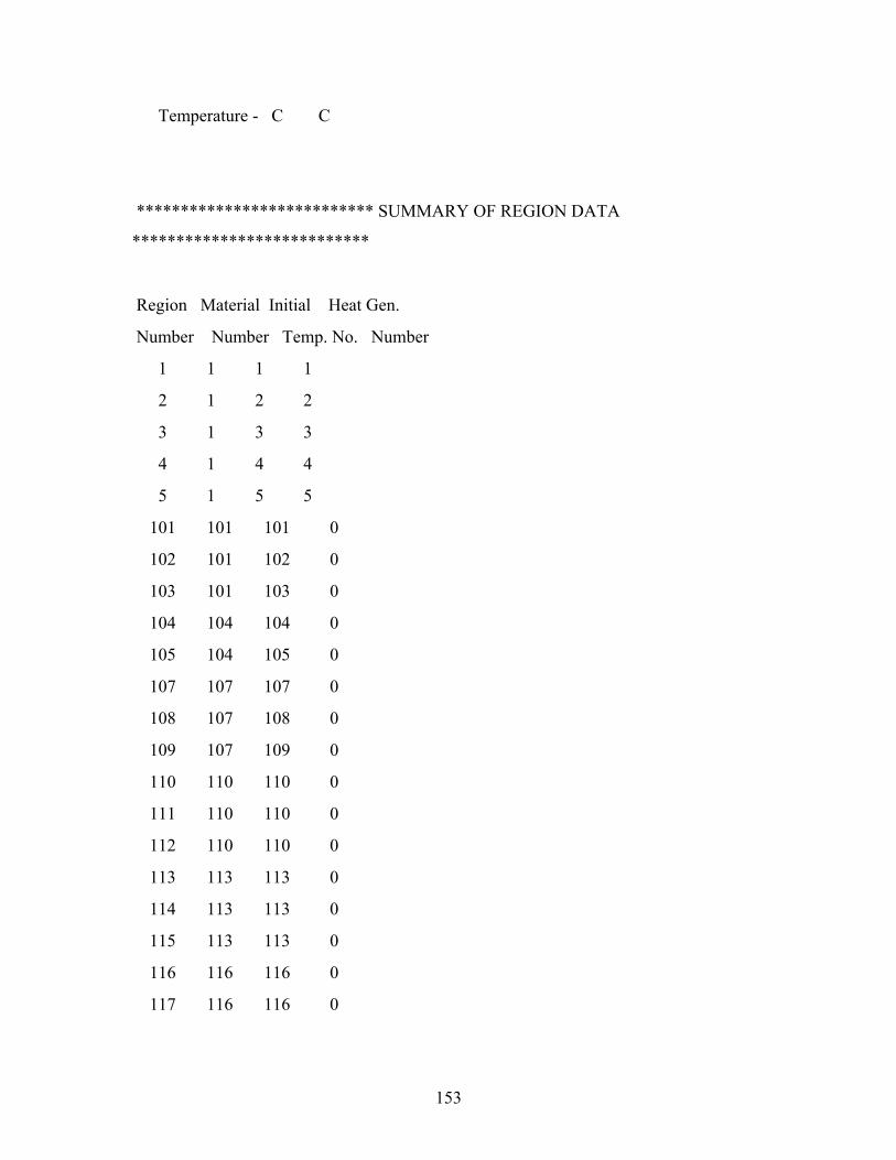
153
Temperature - C C
*************************** SUMMARY OF REGION DATA
***************************
Region Material Initial Heat Gen.
Number Number Temp. No. Number
1 1 1 1
2 1 2 2
3 1 3 3
4 1 4 4
5 1 5 5
101 101 101 0
102 101 102 0
103 101 103 0
104 104 104 0
105 104 105 0
107 107 107 0
108 107 108 0
109 107 109 0
110 110 110 0
111 110 110 0
112 110 110 0
113 113 113 0
114 113 113 0
115 113 113 0
116 116 116 0
117 116 116 0
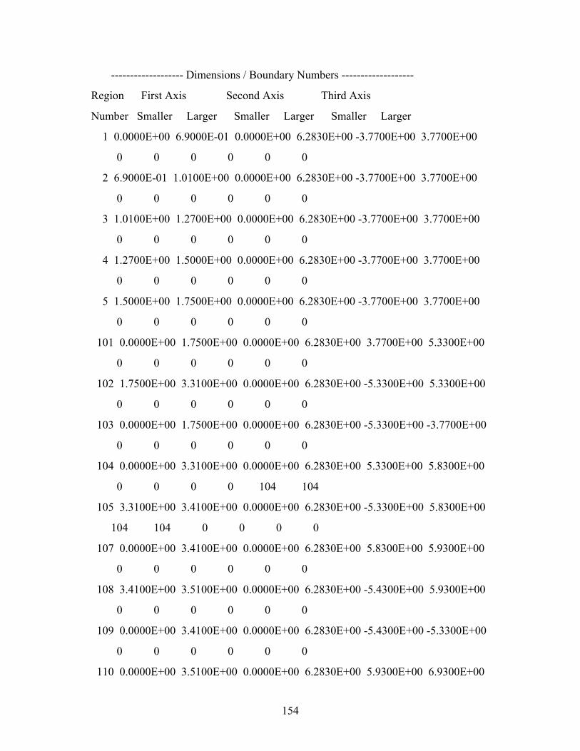
154
------------------- Dimensions / Boundary Numbers -------------------
Region First Axis Second Axis Third Axis
Number Smaller Larger Smaller Larger Smaller Larger
1 0.0000E+00 6.9000E-01 0.0000E+00 6.2830E+00 -3.7700E+00 3.7700E+00
0 0 0 0 0 0
2 6.9000E-01 1.0100E+00 0.0000E+00 6.2830E+00 -3.7700E+00 3.7700E+00
0 0 0 0 0 0
3 1.0100E+00 1.2700E+00 0.0000E+00 6.2830E+00 -3.7700E+00 3.7700E+00
0 0 0 0 0 0
4 1.2700E+00 1.5000E+00 0.0000E+00 6.2830E+00 -3.7700E+00 3.7700E+00
0 0 0 0 0 0
5 1.5000E+00 1.7500E+00 0.0000E+00 6.2830E+00 -3.7700E+00 3.7700E+00
0 0 0 0 0 0
101 0.0000E+00 1.7500E+00 0.0000E+00 6.2830E+00 3.7700E+00 5.3300E+00
0 0 0 0 0 0
102 1.7500E+00 3.3100E+00 0.0000E+00 6.2830E+00 -5.3300E+00 5.3300E+00
0 0 0 0 0 0
103 0.0000E+00 1.7500E+00 0.0000E+00 6.2830E+00 -5.3300E+00 -3.7700E+00
0 0 0 0 0 0
104 0.0000E+00 3.3100E+00 0.0000E+00 6.2830E+00 5.3300E+00 5.8300E+00
0 0 0 0 104 104
105 3.3100E+00 3.4100E+00 0.0000E+00 6.2830E+00 -5.3300E+00 5.8300E+00
104 104 0 0 0 0
107 0.0000E+00 3.4100E+00 0.0000E+00 6.2830E+00 5.8300E+00 5.9300E+00
0 0 0 0 0 0
108 3.4100E+00 3.5100E+00 0.0000E+00 6.2830E+00 -5.4300E+00 5.9300E+00
0 0 0 0 0 0
109 0.0000E+00 3.4100E+00 0.0000E+00 6.2830E+00 -5.4300E+00 -5.3300E+00
0 0 0 0 0 0
110 0.0000E+00 3.5100E+00 0.0000E+00 6.2830E+00 5.9300E+00 6.9300E+00
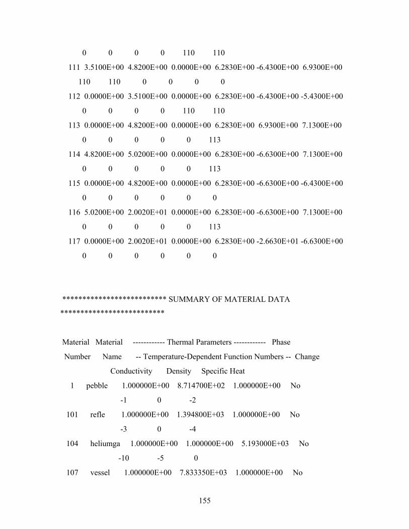
155
0 0 0 0 110 110
111 3.5100E+00 4.8200E+00 0.0000E+00 6.2830E+00 -6.4300E+00 6.9300E+00
110 110 0 0 0 0
112 0.0000E+00 3.5100E+00 0.0000E+00 6.2830E+00 -6.4300E+00 -5.4300E+00
0 0 0 0 110 110
113 0.0000E+00 4.8200E+00 0.0000E+00 6.2830E+00 6.9300E+00 7.1300E+00
0 0 0 0 0 113
114 4.8200E+00 5.0200E+00 0.0000E+00 6.2830E+00 -6.6300E+00 7.1300E+00
0 0 0 0 0 113
115 0.0000E+00 4.8200E+00 0.0000E+00 6.2830E+00 -6.6300E+00 -6.4300E+00
0 0 0 0 0 0
116 5.0200E+00 2.0020E+01 0.0000E+00 6.2830E+00 -6.6300E+00 7.1300E+00
0 0 0 0 0 113
117 0.0000E+00 2.0020E+01 0.0000E+00 6.2830E+00 -2.6630E+01 -6.6300E+00
0 0 0 0 0 0
************************** SUMMARY OF MATERIAL DATA
**************************
Material Material ------------ Thermal Parameters ------------ Phase
Number Name -- Temperature-Dependent Function Numbers -- Change
Conductivity Density Specific Heat
1 pebble 1.000000E+00 8.714700E+02 1.000000E+00 No
-1 0 -2
101 refle 1.000000E+00 1.394800E+03 1.000000E+00 No
-3 0 -4
104 heliumga 1.000000E+00 1.000000E+00 5.193000E+03 No
-10 -5 0
107 vessel 1.000000E+00 7.833350E+03 1.000000E+00 No
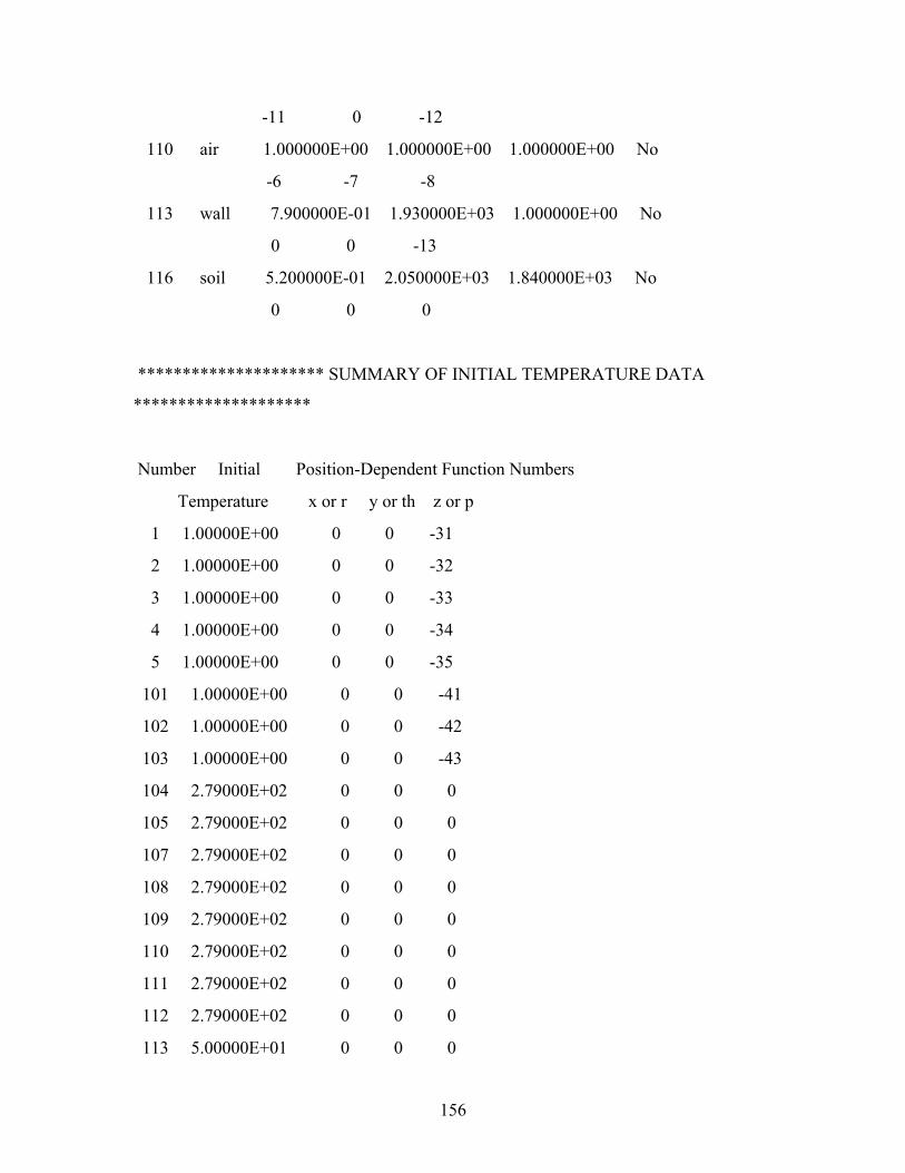
156
-11 0 -12
110 air 1.000000E+00 1.000000E+00 1.000000E+00 No
-6 -7 -8
113 wall 7.900000E-01 1.930000E+03 1.000000E+00 No
0 0 -13
116 soil 5.200000E-01 2.050000E+03 1.840000E+03 No
0 0 0
********************* SUMMARY OF INITIAL TEMPERATURE DATA
********************
Number Initial Position-Dependent Function Numbers
Temperature x or r y or th z or p
1 1.00000E+00 0 0 -31
2 1.00000E+00 0 0 -32
3 1.00000E+00 0 0 -33
4 1.00000E+00 0 0 -34
5 1.00000E+00 0 0 -35
101 1.00000E+00 0 0 -41
102 1.00000E+00 0 0 -42
103 1.00000E+00 0 0 -43
104 2.79000E+02 0 0 0
105 2.79000E+02 0 0 0
107 2.79000E+02 0 0 0
108 2.79000E+02 0 0 0
109 2.79000E+02 0 0 0
110 2.79000E+02 0 0 0
111 2.79000E+02 0 0 0
112 2.79000E+02 0 0 0
113 5.00000E+01 0 0 0
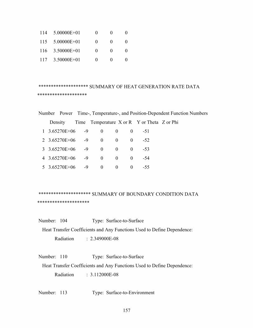
157
114 5.00000E+01 0 0 0
115 5.00000E+01 0 0 0
116 3.50000E+01 0 0 0
117 3.50000E+01 0 0 0
******************** SUMMARY OF HEAT GENERATION RATE DATA
********************
Number Power Time-, Temperature-, and Position-Dependent Function Numbers
Density Time Temperature X or R Y or Theta Z or Phi
1 3.65270E+06 -9 0 0 0 -51
2 3.65270E+06 -9 0 0 0 -52
3 3.65270E+06 -9 0 0 0 -53
4 3.65270E+06 -9 0 0 0 -54
5 3.65270E+06 -9 0 0 0 -55
********************* SUMMARY OF BOUNDARY CONDITION DATA
*********************
Number: 104 Type: Surface-to-Surface
Heat Transfer Coefficients and Any Functions Used to Define Dependence:
Radiation : 2.349000E-08
Number: 110 Type: Surface-to-Surface
Heat Transfer Coefficients and Any Functions Used to Define Dependence:
Radiation : 3.112000E-08
Number: 113 Type: Surface-to-Environment
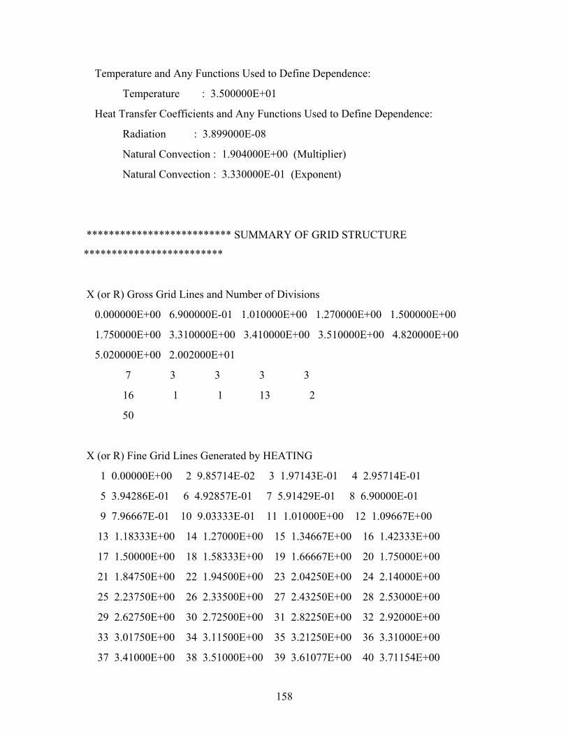
158
Temperature and Any Functions Used to Define Dependence:
Temperature : 3.500000E+01
Heat Transfer Coefficients and Any Functions Used to Define Dependence:
Radiation : 3.899000E-08
Natural Convection : 1.904000E+00 (Multiplier)
Natural Convection : 3.330000E-01 (Exponent)
************************** SUMMARY OF GRID STRUCTURE
*************************
X (or R) Gross Grid Lines and Number of Divisions
0.000000E+00 6.900000E-01 1.010000E+00 1.270000E+00 1.500000E+00
1.750000E+00 3.310000E+00 3.410000E+00 3.510000E+00 4.820000E+00
5.020000E+00 2.002000E+01
7 3 3 3 3
16 1 1 13 2
50
X (or R) Fine Grid Lines Generated by HEATING
1 0.00000E+00 2 9.85714E-02 3 1.97143E-01 4 2.95714E-01
5 3.94286E-01 6 4.92857E-01 7 5.91429E-01 8 6.90000E-01
9 7.96667E-01 10 9.03333E-01 11 1.01000E+00 12 1.09667E+00
13 1.18333E+00 14 1.27000E+00 15 1.34667E+00 16 1.42333E+00
17 1.50000E+00 18 1.58333E+00 19 1.66667E+00 20 1.75000E+00
21 1.84750E+00 22 1.94500E+00 23 2.04250E+00 24 2.14000E+00
25 2.23750E+00 26 2.33500E+00 27 2.43250E+00 28 2.53000E+00
29 2.62750E+00 30 2.72500E+00 31 2.82250E+00 32 2.92000E+00
33 3.01750E+00 34 3.11500E+00 35 3.21250E+00 36 3.31000E+00
37 3.41000E+00 38 3.51000E+00 39 3.61077E+00 40 3.71154E+00

159
41 3.81231E+00 42 3.91308E+00 43 4.01385E+00 44 4.11462E+00
45 4.21538E+00 46 4.31615E+00 47 4.41692E+00 48 4.51769E+00
49 4.61846E+00 50 4.71923E+00 51 4.82000E+00 52 4.92000E+00
53 5.02000E+00 54 5.32000E+00 55 5.62000E+00 56 5.92000E+00
57 6.22000E+00 58 6.52000E+00 59 6.82000E+00 60 7.12000E+00
61 7.42000E+00 62 7.72000E+00 63 8.02000E+00 64 8.32000E+00
65 8.62000E+00 66 8.92000E+00 67 9.22000E+00 68 9.52000E+00
69 9.82000E+00 70 1.01200E+01 71 1.04200E+01 72 1.07200E+01
73 1.10200E+01 74 1.13200E+01 75 1.16200E+01 76 1.19200E+01
77 1.22200E+01 78 1.25200E+01 79 1.28200E+01 80 1.31200E+01
81 1.34200E+01 82 1.37200E+01 83 1.40200E+01 84 1.43200E+01
85 1.46200E+01 86 1.49200E+01 87 1.52200E+01 88 1.55200E+01
89 1.58200E+01 90 1.61200E+01 91 1.64200E+01 92 1.67200E+01
93 1.70200E+01 94 1.73200E+01 95 1.76200E+01 96 1.79200E+01
97 1.82200E+01 98 1.85200E+01 99 1.88200E+01 100 1.91200E+01
101 1.94200E+01 102 1.97200E+01 103 2.00200E+01
Y (or Theta) Gross Grid Lines and Number of Divisions
0.000000E+00 6.283000E+00
2
Y (or Theta) Fine Grid Lines Generated by HEATING
1 0.00000E+00 2 3.14150E+00 3 6.28300E+00
Z (or Phi) Gross Grid Lines and Number of Divisions
-2.663000E+01 -6.630000E+00 -6.430000E+00 -5.430000E+00 -5.330000E+00
-3.770000E+00 3.770000E+00 5.330000E+00 5.830000E+00 5.930000E+00
6.930000E+00 7.130000E+00
50 2 10 1 16
75 16 5 1 10
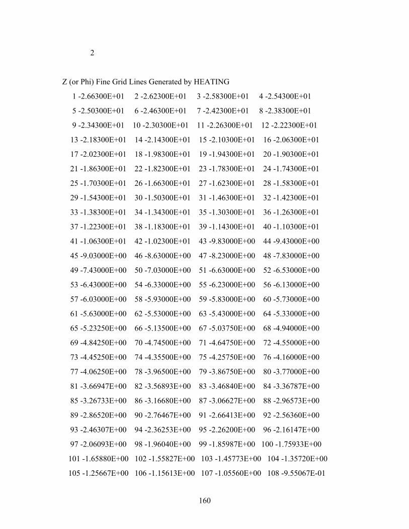
160
2
Z (or Phi) Fine Grid Lines Generated by HEATING
1 -2.66300E+01 2 -2.62300E+01 3 -2.58300E+01 4 -2.54300E+01
5 -2.50300E+01 6 -2.46300E+01 7 -2.42300E+01 8 -2.38300E+01
9 -2.34300E+01 10 -2.30300E+01 11 -2.26300E+01 12 -2.22300E+01
13 -2.18300E+01 14 -2.14300E+01 15 -2.10300E+01 16 -2.06300E+01
17 -2.02300E+01 18 -1.98300E+01 19 -1.94300E+01 20 -1.90300E+01
21 -1.86300E+01 22 -1.82300E+01 23 -1.78300E+01 24 -1.74300E+01
25 -1.70300E+01 26 -1.66300E+01 27 -1.62300E+01 28 -1.58300E+01
29 -1.54300E+01 30 -1.50300E+01 31 -1.46300E+01 32 -1.42300E+01
33 -1.38300E+01 34 -1.34300E+01 35 -1.30300E+01 36 -1.26300E+01
37 -1.22300E+01 38 -1.18300E+01 39 -1.14300E+01 40 -1.10300E+01
41 -1.06300E+01 42 -1.02300E+01 43 -9.83000E+00 44 -9.43000E+00
45 -9.03000E+00 46 -8.63000E+00 47 -8.23000E+00 48 -7.83000E+00
49 -7.43000E+00 50 -7.03000E+00 51 -6.63000E+00 52 -6.53000E+00
53 -6.43000E+00 54 -6.33000E+00 55 -6.23000E+00 56 -6.13000E+00
57 -6.03000E+00 58 -5.93000E+00 59 -5.83000E+00 60 -5.73000E+00
61 -5.63000E+00 62 -5.53000E+00 63 -5.43000E+00 64 -5.33000E+00
65 -5.23250E+00 66 -5.13500E+00 67 -5.03750E+00 68 -4.94000E+00
69 -4.84250E+00 70 -4.74500E+00 71 -4.64750E+00 72 -4.55000E+00
73 -4.45250E+00 74 -4.35500E+00 75 -4.25750E+00 76 -4.16000E+00
77 -4.06250E+00 78 -3.96500E+00 79 -3.86750E+00 80 -3.77000E+00
81 -3.66947E+00 82 -3.56893E+00 83 -3.46840E+00 84 -3.36787E+00
85 -3.26733E+00 86 -3.16680E+00 87 -3.06627E+00 88 -2.96573E+00
89 -2.86520E+00 90 -2.76467E+00 91 -2.66413E+00 92 -2.56360E+00
93 -2.46307E+00 94 -2.36253E+00 95 -2.26200E+00 96 -2.16147E+00
97 -2.06093E+00 98 -1.96040E+00 99 -1.85987E+00 100 -1.75933E+00
101 -1.65880E+00 102 -1.55827E+00 103 -1.45773E+00 104 -1.35720E+00
105 -1.25667E+00 106 -1.15613E+00 107 -1.05560E+00 108 -9.55067E-01
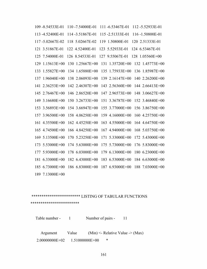
161
109 -8.54533E-01 110 -7.54000E-01 111 -6.53467E-01 112 -5.52933E-01
113 -4.52400E-01 114 -3.51867E-01 115 -2.51333E-01 116 -1.50800E-01
117 -5.02667E-02 118 5.02667E-02 119 1.50800E-01 120 2.51333E-01
121 3.51867E-01 122 4.52400E-01 123 5.52933E-01 124 6.53467E-01
125 7.54000E-01 126 8.54533E-01 127 9.55067E-01 128 1.05560E+00
129 1.15613E+00 130 1.25667E+00 131 1.35720E+00 132 1.45773E+00
133 1.55827E+00 134 1.65880E+00 135 1.75933E+00 136 1.85987E+00
137 1.96040E+00 138 2.06093E+00 139 2.16147E+00 140 2.26200E+00
141 2.36253E+00 142 2.46307E+00 143 2.56360E+00 144 2.66413E+00
145 2.76467E+00 146 2.86520E+00 147 2.96573E+00 148 3.06627E+00
149 3.16680E+00 150 3.26733E+00 151 3.36787E+00 152 3.46840E+00
153 3.56893E+00 154 3.66947E+00 155 3.77000E+00 156 3.86750E+00
157 3.96500E+00 158 4.06250E+00 159 4.16000E+00 160 4.25750E+00
161 4.35500E+00 162 4.45250E+00 163 4.55000E+00 164 4.64750E+00
165 4.74500E+00 166 4.84250E+00 167 4.94000E+00 168 5.03750E+00
169 5.13500E+00 170 5.23250E+00 171 5.33000E+00 172 5.43000E+00
173 5.53000E+00 174 5.63000E+00 175 5.73000E+00 176 5.83000E+00
177 5.93000E+00 178 6.03000E+00 179 6.13000E+00 180 6.23000E+00
181 6.33000E+00 182 6.43000E+00 183 6.53000E+00 184 6.63000E+00
185 6.73000E+00 186 6.83000E+00 187 6.93000E+00 188 7.03000E+00
189 7.13000E+00
************************ LISTING OF TABULAR FUNCTIONS
************************
Table number - 1 Number of pairs - 11
Argument Value (Min) <- Relative Value -> (Max)
2.00000000E+02 1.51000000E+00 *
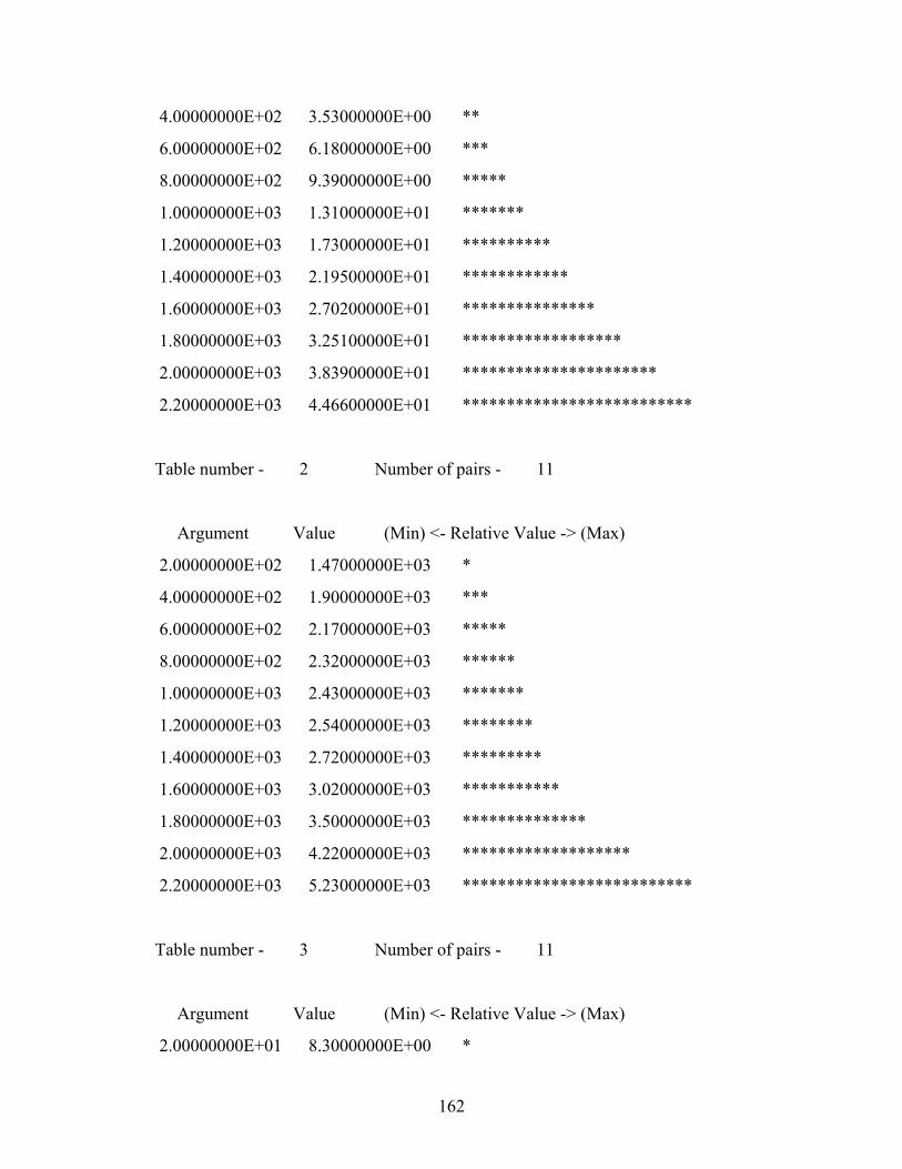
162
4.00000000E+02 3.53000000E+00 **
6.00000000E+02 6.18000000E+00 ***
8.00000000E+02 9.39000000E+00 *****
1.00000000E+03 1.31000000E+01 *******
1.20000000E+03 1.73000000E+01 **********
1.40000000E+03 2.19500000E+01 ************
1.60000000E+03 2.70200000E+01 ***************
1.80000000E+03 3.25100000E+01 ******************
2.00000000E+03 3.83900000E+01 **********************
2.20000000E+03 4.46600000E+01 **************************
Table number - 2 Number of pairs - 11
Argument Value (Min) <- Relative Value -> (Max)
2.00000000E+02 1.47000000E+03 *
4.00000000E+02 1.90000000E+03 ***
6.00000000E+02 2.17000000E+03 *****
8.00000000E+02 2.32000000E+03 ******
1.00000000E+03 2.43000000E+03 *******
1.20000000E+03 2.54000000E+03 ********
1.40000000E+03 2.72000000E+03 *********
1.60000000E+03 3.02000000E+03 ***********
1.80000000E+03 3.50000000E+03 **************
2.00000000E+03 4.22000000E+03 *******************
2.20000000E+03 5.23000000E+03 **************************
Table number - 3 Number of pairs - 11
Argument Value (Min) <- Relative Value -> (Max)
2.00000000E+01 8.30000000E+00 *
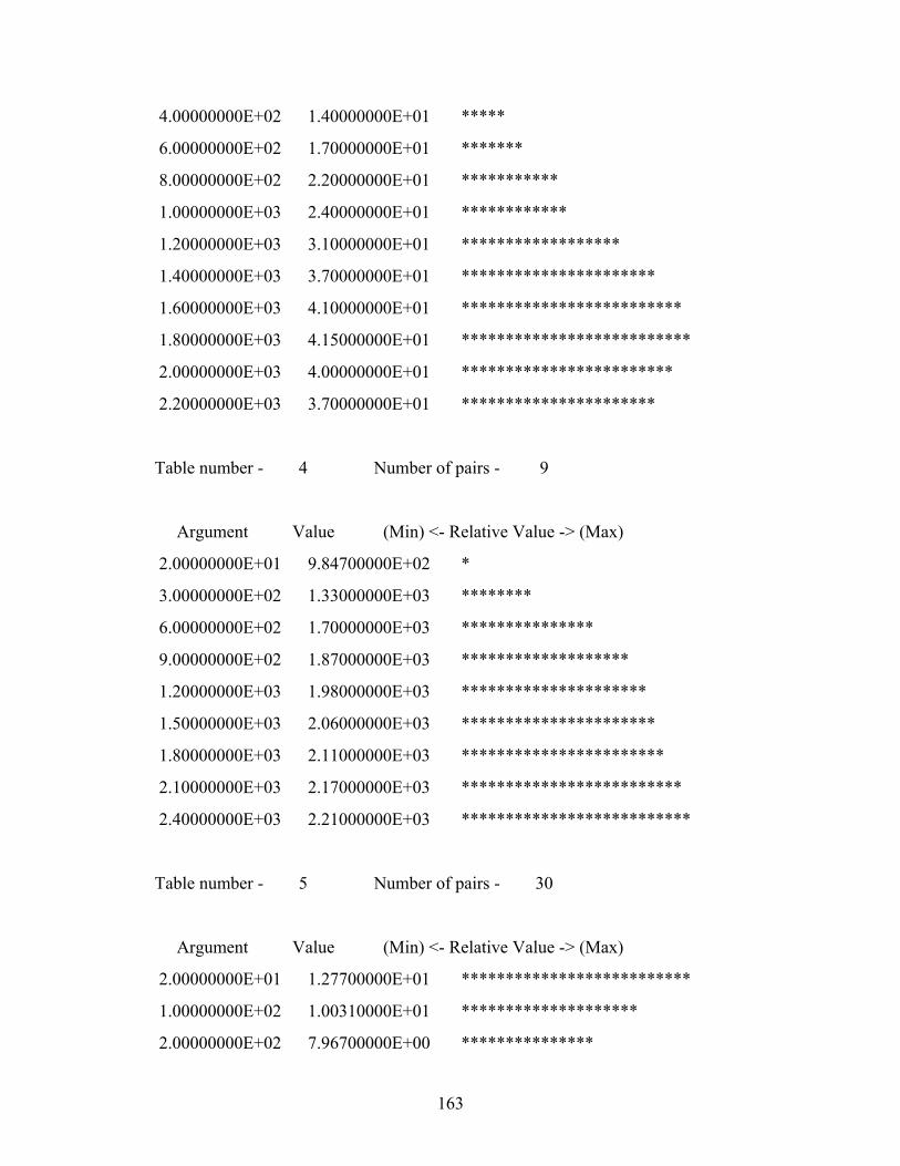
163
4.00000000E+02 1.40000000E+01 *****
6.00000000E+02 1.70000000E+01 *******
8.00000000E+02 2.20000000E+01 ***********
1.00000000E+03 2.40000000E+01 ************
1.20000000E+03 3.10000000E+01 ******************
1.40000000E+03 3.70000000E+01 **********************
1.60000000E+03 4.10000000E+01 *************************
1.80000000E+03 4.15000000E+01 **************************
2.00000000E+03 4.00000000E+01 ************************
2.20000000E+03 3.70000000E+01 **********************
Table number - 4 Number of pairs - 9
Argument Value (Min) <- Relative Value -> (Max)
2.00000000E+01 9.84700000E+02 *
3.00000000E+02 1.33000000E+03 ********
6.00000000E+02 1.70000000E+03 ***************
9.00000000E+02 1.87000000E+03 *******************
1.20000000E+03 1.98000000E+03 *********************
1.50000000E+03 2.06000000E+03 **********************
1.80000000E+03 2.11000000E+03 ***********************
2.10000000E+03 2.17000000E+03 *************************
2.40000000E+03 2.21000000E+03 **************************
Table number - 5 Number of pairs - 30
Argument Value (Min) <- Relative Value -> (Max)
2.00000000E+01 1.27700000E+01 **************************
1.00000000E+02 1.00310000E+01 ********************
2.00000000E+02 7.96700000E+00 ***************
164
3.00000000E+02 6.60600000E+00 ************
4.00000000E+02 5.64100000E+00 **********
5.00000000E+02 4.92200000E+00 *********
6.00000000E+02 4.36500000E+00 *******
7.00000000E+02 3.92200000E+00 ******
8.00000000E+02 3.56000000E+00 ******
9.00000000E+02 3.25900000E+00 *****
1.00000000E+03 3.00500000E+00 ****
1.10000000E+03 2.78800000E+00 ****
1.20000000E+03 2.60000000E+00 ****
1.30000000E+03 2.43600000E+00 ***
1.40000000E+03 2.29100000E+00 ***
1.50000000E+03 2.16200000E+00 ***
1.60000000E+03 2.04800000E+00 **
1.70000000E+03 1.94400000E+00 **
1.80000000E+03 1.85100000E+00 **
1.90000000E+03 1.76600000E+00 **
2.00000000E+03 1.68900000E+00 **
2.10000000E+03 1.61800000E+00 *
2.20000000E+03 1.55300000E+00 *
2.30000000E+03 1.49200000E+00 *
2.40000000E+03 1.43700000E+00 *
2.50000000E+03 1.38500000E+00 *
2.60000000E+03 1.33700000E+00 *
2.70000000E+03 1.29200000E+00 *
2.80000000E+03 1.25000000E+00 *
2.90000000E+03 1.21100000E+00 *
Table number - 6 Number of pairs - 13
165
Argument Value (Min) <- Relative Value -> (Max)
0.00000000E+00 2.41500000E-02 *
1.00000000E+02 3.06600000E-02 **
2.00000000E+02 3.70900000E-02 ****
3.00000000E+02 4.32600000E-02 ******
4.00000000E+02 4.90100000E-02 ********
5.00000000E+02 5.48100000E-02 *********
6.00000000E+02 6.04800000E-02 ***********
7.00000000E+02 6.51000000E-02 ************
8.00000000E+02 7.01400000E-02 **************
9.00000000E+02 7.44700000E-02 ***************
1.00000000E+03 7.89600000E-02 ****************
1.10000000E+03 8.29500000E-02 *****************
1.80000000E+03 1.10880000E-01 **************************
Table number - 7 Number of pairs - 15
Argument Value (Min) <- Relative Value -> (Max)
2.00000000E+01 1.20500000E+00 **************************
5.00000000E+01 1.09300000E+00 ***********************
1.00000000E+02 9.46000000E-01 *******************
2.00000000E+02 7.46000000E-01 ***************
3.00000000E+02 6.15000000E-01 ************
4.00000000E+02 5.24000000E-01 **********
5.00000000E+02 4.56000000E-01 ********
6.00000000E+02 4.04000000E-01 *******
7.00000000E+02 3.62000000E-01 ******
8.00000000E+02 3.29000000E-01 *****
9.00000000E+02 3.01000000E-01 ****
1.00000000E+03 2.77000000E-01 ****
166
1.10000000E+03 2.57000000E-01 ***
1.20000000E+03 2.39000000E-01 ***
1.80000000E+03 1.31000000E-01 *
Table number - 8 Number of pairs - 15
Argument Value (Min) <- Relative Value -> (Max)
2.00000000E+01 1.00500000E+03 *
5.00000000E+01 1.00500000E+03 *
1.00000000E+02 1.00900000E+03 *
2.00000000E+02 1.02600000E+03 **
3.00000000E+02 1.04700000E+03 ****
4.00000000E+02 1.06800000E+03 ******
5.00000000E+02 1.09300000E+03 ********
6.00000000E+02 1.11400000E+03 **********
7.00000000E+02 1.13500000E+03 ************
8.00000000E+02 1.15600000E+03 **************
9.00000000E+02 1.17200000E+03 ***************
1.00000000E+03 1.18500000E+03 ****************
1.10000000E+03 1.19700000E+03 *****************
1.20000000E+03 1.21000000E+03 *******************
1.80000000E+03 1.28800000E+03 **************************
Table number - 9 Number of pairs - 13
Argument Value (Min) <- Relative Value -> (Max)
0.00000000E+00 1.00000000E+00 **************************
1.00000000E+00 4.20000000E-02 **
2.00000000E+00 3.90000000E-02 *
5.00000000E+00 3.60000000E-02 *
167
1.00000000E+01 3.30000000E-02 *
8.00000000E+01 3.20000000E-02 *
1.50000000E+02 2.80000000E-02 *
1.00000000E+03 1.80000000E-02 *
1.00000000E+04 8.87000000E-03 *
1.00000000E+05 4.28000000E-03 *
1.00000000E+06 1.89000000E-03 *
1.00000000E+07 6.55000000E-04 *
1.00000000E+08 1.11000000E-04 *
Table number - 10 Number of pairs - 15
Argument Value (Min) <- Relative Value -> (Max)
2.70000000E+01 1.56400000E-01 *
7.70000000E+01 1.69200000E-01 *
1.27000000E+02 1.87200000E-01 ***
2.27000000E+02 2.20600000E-01 *****
3.27000000E+02 2.51600000E-01 ********
4.27000000E+02 2.79200000E-01 **********
5.27000000E+02 3.05200000E-01 ************
6.27000000E+02 3.31200000E-01 **************
7.27000000E+02 3.35200000E-01 **************
8.27000000E+02 3.80200000E-01 ******************
9.27000000E+02 4.06000000E-01 ********************
1.02700000E+03 4.30200000E-01 **********************
1.12700000E+03 4.55200000E-01 ************************
1.22700000E+03 4.79200000E-01 **************************
1.82700000E+03 4.79200000E-01 **************************
Table number - 11 Number of pairs - 7
168
Argument Value (Min) <- Relative Value -> (Max)
2.00000000E+01 4.43200000E+01 **************************
3.00000000E+02 3.95300000E+01 **********************
6.00000000E+02 3.43900000E+01 *****************
9.00000000E+02 2.92600000E+01 *************
1.20000000E+03 2.41200000E+01 *********
1.50000000E+03 1.89900000E+01 *****
1.80000000E+03 1.38500000E+01 *
Table number - 12 Number of pairs - 11
Argument Value (Min) <- Relative Value -> (Max)
2.00000000E+01 4.92990000E+02 *
1.00000000E+02 5.11360000E+02 *
2.00000000E+02 5.29540000E+02 *
3.00000000E+02 5.44100000E+02 *
6.00000000E+02 5.84200000E+02 *
9.00000000E+02 6.57000000E+02 **
1.20000000E+03 8.11600000E+02 ***
1.50000000E+03 1.09700000E+03 ******
1.80000000E+03 1.56200000E+03 **********
2.10000000E+03 2.25600000E+03 *****************
2.40000000E+03 3.22700000E+03 **************************
Table number - 13 Number of pairs - 12
Argument Value (Min) <- Relative Value -> (Max)
2.00000000E+01 9.70000000E+02 *
2.00000000E+02 1.30000000E+03 ***********
169
3.00000000E+02 1.20000000E+03 ********
4.00000000E+02 1.40000000E+03 **************
5.00000000E+02 1.52000000E+03 *****************
6.00000000E+02 1.70000000E+03 ***********************
7.00000000E+02 1.78000000E+03 **************************
8.00000000E+02 1.77000000E+03 *************************
9.00000000E+02 1.76000000E+03 *************************
1.00000000E+03 1.75000000E+03 *************************
1.10000000E+03 1.74000000E+03 ************************
1.50000000E+03 1.74000000E+03 ************************
Table number - 31 Number of pairs - 15
Argument Value (Min) <- Relative Value -> (Max)
-3.77000000E+00 8.59100000E+02 *************************
-3.61450000E+00 8.62900000E+02 **************************
-3.55090000E+00 8.62300000E+02 *************************
-3.41200000E+00 8.60800000E+02 *************************
-2.75910000E+00 8.14400000E+02 **********************
-2.10620000E+00 7.53100000E+02 *****************
-1.45330000E+00 7.21300000E+02 **************
-8.00400000E-01 6.94800000E+02 ************
-1.47500000E-01 6.68800000E+02 **********
5.05500000E-01 6.40200000E+02 ********
1.15840000E+00 6.13100000E+02 ******
1.81130000E+00 5.88400000E+02 ****
2.46420000E+00 5.67500000E+02 **
3.11710000E+00 5.51700000E+02 *
3.77000000E+00 5.42500000E+02 *
170
Table number - 32 Number of pairs - 15
Argument Value (Min) <- Relative Value -> (Max)
-3.77000000E+00 9.73000000E+02 *************************
-3.61450000E+00 9.78200000E+02 **************************
-3.55090000E+00 9.76200000E+02 *************************
-3.41200000E+00 9.77400000E+02 *************************
-2.75910000E+00 9.57600000E+02 ************************
-2.10620000E+00 9.19100000E+02 **********************
-1.45330000E+00 8.81800000E+02 ********************
-8.00400000E-01 8.39700000E+02 *****************
-1.47500000E-01 7.93700000E+02 ***************
5.05500000E-01 7.43700000E+02 ************
1.15840000E+00 6.92600000E+02 *********
1.81130000E+00 6.43000000E+02 ******
2.46420000E+00 6.00100000E+02 ****
3.11710000E+00 5.67700000E+02 **
3.77000000E+00 5.48100000E+02 *
Table number - 33 Number of pairs - 15
Argument Value (Min) <- Relative Value -> (Max)
-3.77000000E+00 9.68900000E+02 *************************
-3.61450000E+00 9.71800000E+02 *************************
-3.55090000E+00 9.77400000E+02 *************************
-3.41200000E+00 9.80500000E+02 **************************
-2.75910000E+00 9.66500000E+02 *************************
-2.10620000E+00 9.36800000E+02 ***********************
-1.45330000E+00 9.03500000E+02 *********************
-8.00400000E-01 8.62000000E+02 *******************
171
-1.47500000E-01 8.13200000E+02 ****************
5.05500000E-01 7.60000000E+02 *************
1.15840000E+00 7.04700000E+02 **********
1.81130000E+00 6.50600000E+02 ******
2.46420000E+00 6.04100000E+02 ****
3.11710000E+00 5.70200000E+02 **
3.77000000E+00 5.49400000E+02 *
Table number - 34 Number of pairs - 13
Argument Value (Min) <- Relative Value -> (Max)
-3.77000000E+00 9.73100000E+02 *************************
-3.41200000E+00 9.78500000E+02 **************************
-2.75910000E+00 9.57700000E+02 ************************
-2.10620000E+00 9.24500000E+02 **********************
-1.45330000E+00 8.90500000E+02 ********************
-8.00400000E-01 8.47800000E+02 ******************
-1.47500000E-01 7.99700000E+02 ***************
5.05500000E-01 7.47200000E+02 ************
1.15840000E+00 6.93100000E+02 *********
1.81130000E+00 6.40500000E+02 ******
2.46420000E+00 5.96500000E+02 ***
3.11710000E+00 5.66200000E+02 **
3.77000000E+00 5.48500000E+02 *
Table number - 35 Number of pairs - 13
Argument Value (Min) <- Relative Value -> (Max)
-3.77000000E+00 9.26600000E+02 ***********************
-3.41200000E+00 9.63300000E+02 **************************
172
-2.75910000E+00 9.42800000E+02 ************************
-2.10620000E+00 9.12500000E+02 **********************
-1.45330000E+00 8.79700000E+02 ********************
-8.00400000E-01 8.38600000E+02 ******************
-1.47500000E-01 7.92200000E+02 ***************
5.05500000E-01 7.41200000E+02 ************
1.15840000E+00 6.88300000E+02 *********
1.81130000E+00 6.36800000E+02 ******
2.46420000E+00 5.93800000E+02 ***
3.11710000E+00 5.64800000E+02 *
3.77000000E+00 5.48200000E+02 *
Table number - 41 Number of pairs - 7
Argument Value (Min) <- Relative Value -> (Max)
3.77000000E+00 5.49400000E+02 **************************
4.61000000E+00 5.40500000E+02 **********************
4.74000000E+00 5.40100000E+02 **********************
4.86000000E+00 5.39800000E+02 **********************
4.96000000E+00 5.39300000E+02 **********************
5.06000000E+00 5.37100000E+02 *********************
5.33000000E+00 4.79800000E+02 *
Table number - 42 Number of pairs - 27
Argument Value (Min) <- Relative Value -> (Max)
-5.33000000E+00 2.51000000E+01 *
-4.56000000E+00 7.25500000E+02 *********************
-4.28000000E+00 7.26800000E+02 *********************
-4.14690000E+00 7.28200000E+02 *********************
173
-4.01960000E+00 7.30300000E+02 *********************
-3.87490000E+00 7.34700000E+02 *********************
-3.73370000E+00 7.44100000E+02 *********************
-3.61450000E+00 7.71200000E+02 **********************
-3.55090000E+00 8.34300000E+02 ************************
-3.41200000E+00 8.89800000E+02 **************************
-2.75910000E+00 8.82000000E+02 *************************
-2.10620000E+00 8.56800000E+02 *************************
-1.45330000E+00 8.28800000E+02 ************************
-8.00400000E-01 7.93900000E+02 ***********************
-1.47500000E-01 7.54500000E+02 **********************
5.05500000E-01 7.11200000E+02 ********************
1.15840000E+00 6.66300000E+02 *******************
1.81130000E+00 6.22700000E+02 ******************
2.46420000E+00 5.86200000E+02 *****************
3.11710000E+00 5.61400000E+02 ****************
3.77000000E+00 5.47300000E+02 ****************
4.61000000E+00 5.39500000E+02 ***************
4.73500000E+00 5.36400000E+02 ***************
4.86000000E+00 5.32000000E+02 ***************
4.96000000E+00 5.29500000E+02 ***************
5.06000000E+00 5.25100000E+02 ***************
5.33000000E+00 4.76400000E+02 **************
Table number - 43 Number of pairs - 2
Argument Value (Min) <- Relative Value -> (Max)
-5.33000000E+00 8.73300000E+02 *
-3.77000000E+00 9.73100000E+02 **************************
174
Table number - 51 Number of pairs - 11
Argument Value (Min) <- Relative Value -> (Max)
-3.77000000E+00 1.11260000E-02 ***********
-3.35113000E+00 1.11260000E-02 ***********
-2.51335000E+00 1.41140000E-02 *****************
-1.67557000E+00 1.62320000E-02 **********************
-8.37790000E-01 1.77340000E-02 *************************
-1.00000000E-05 1.80810000E-02 **************************
8.37770000E-01 1.71290000E-02 ************************
1.67555000E+00 1.42120000E-02 ******************
2.51333000E+00 1.02950000E-02 **********
3.35111000E+00 5.81800000E-03 *
3.77000000E+00 5.81800000E-03 *
Table number - 52 Number of pairs - 12
Argument Value (Min) <- Relative Value -> (Max)
-3.77000000E+00 7.62057000E-01 *********
-3.39300000E+00 7.62057000E-01 *********
-2.63900000E+00 9.26468000E-01 *************
-1.88500000E+00 1.13850900E+00 *******************
-1.13100000E+00 1.30825400E+00 ***********************
-3.77000000E-01 1.40929800E+00 **************************
3.77000000E-01 1.40265800E+00 *************************
1.13100000E+00 1.28914100E+00 **********************
1.88500000E+00 1.03887800E+00 ****************
2.63900000E+00 7.28655000E-01 ********
3.39300000E+00 4.21222000E-01 *
3.77000000E+00 4.21222000E-01 *
175
Table number - 53 Number of pairs - 13
Argument Value (Min) <- Relative Value -> (Max)
-3.77000000E+00 1.02851600E+00 **********
-3.42723000E+00 1.02851600E+00 **********
-2.74178000E+00 1.25264700E+00 **************
-2.05633000E+00 1.44301500E+00 *****************
-1.37088000E+00 1.65159500E+00 *********************
-6.85430000E-01 1.80087800E+00 ************************
2.00000000E-05 1.87804700E+00 **************************
6.85470000E-01 1.85455400E+00 *************************
1.37092000E+00 1.70458300E+00 **********************
2.05637000E+00 1.32731500E+00 ***************
2.74182000E+00 9.15033000E-01 *******
3.42727000E+00 5.41849000E-01 *
3.77000000E+00 5.41849000E-01 *
Table number - 54 Number of pairs - 14
Argument Value (Min) <- Relative Value -> (Max)
-3.77000000E+00 8.44293000E-01 ********
-3.45580000E+00 8.44293000E-01 ********
-2.82747000E+00 9.45036000E-01 **********
-2.19914000E+00 1.11287600E+00 **************
-1.57081000E+00 1.26225800E+00 *****************
-9.42480000E-01 1.45472400E+00 *********************
-3.14150000E-01 1.59854100E+00 ************************
3.14180000E-01 1.69581000E+00 **************************
9.42510000E-01 1.67678900E+00 *************************
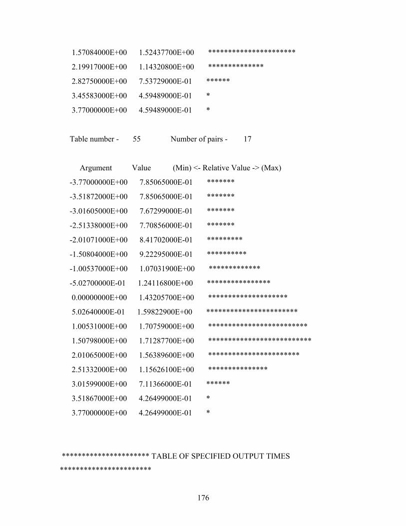
176
1.57084000E+00 1.52437700E+00 **********************
2.19917000E+00 1.14320800E+00 **************
2.82750000E+00 7.53729000E-01 ******
3.45583000E+00 4.59489000E-01 *
3.77000000E+00 4.59489000E-01 *
Table number - 55 Number of pairs - 17
Argument Value (Min) <- Relative Value -> (Max)
-3.77000000E+00 7.85065000E-01 *******
-3.51872000E+00 7.85065000E-01 *******
-3.01605000E+00 7.67299000E-01 *******
-2.51338000E+00 7.70856000E-01 *******
-2.01071000E+00 8.41702000E-01 *********
-1.50804000E+00 9.22295000E-01 **********
-1.00537000E+00 1.07031900E+00 *************
-5.02700000E-01 1.24116800E+00 ****************
0.00000000E+00 1.43205700E+00 ********************
5.02640000E-01 1.59822900E+00 ***********************
1.00531000E+00 1.70759000E+00 *************************
1.50798000E+00 1.71287700E+00 **************************
2.01065000E+00 1.56389600E+00 ***********************
2.51332000E+00 1.15626100E+00 ***************
3.01599000E+00 7.11366000E-01 ******
3.51867000E+00 4.26499000E-01 *
3.77000000E+00 4.26499000E-01 *
********************** TABLE OF SPECIFIED OUTPUT TIMES
***********************
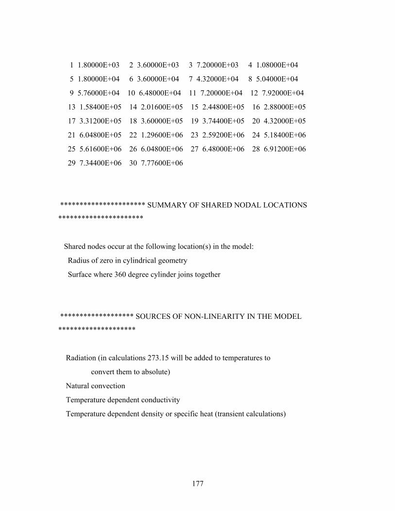
177
1 1.80000E+03 2 3.60000E+03 3 7.20000E+03 4 1.08000E+04
5 1.80000E+04 6 3.60000E+04 7 4.32000E+04 8 5.04000E+04
9 5.76000E+04 10 6.48000E+04 11 7.20000E+04 12 7.92000E+04
13 1.58400E+05 14 2.01600E+05 15 2.44800E+05 16 2.88000E+05
17 3.31200E+05 18 3.60000E+05 19 3.74400E+05 20 4.32000E+05
21 6.04800E+05 22 1.29600E+06 23 2.59200E+06 24 5.18400E+06
25 5.61600E+06 26 6.04800E+06 27 6.48000E+06 28 6.91200E+06
29 7.34400E+06 30 7.77600E+06
********************** SUMMARY OF SHARED NODAL LOCATIONS
**********************
Shared nodes occur at the following location(s) in the model:
Radius of zero in cylindrical geometry
Surface where 360 degree cylinder joins together
******************* SOURCES OF NON-LINEARITY IN THE MODEL
********************
Radiation (in calculations 273.15 will be added to temperatures to
convert them to absolute)
Natural convection
Temperature dependent conductivity
Temperature dependent density or specific heat (transient calculations)
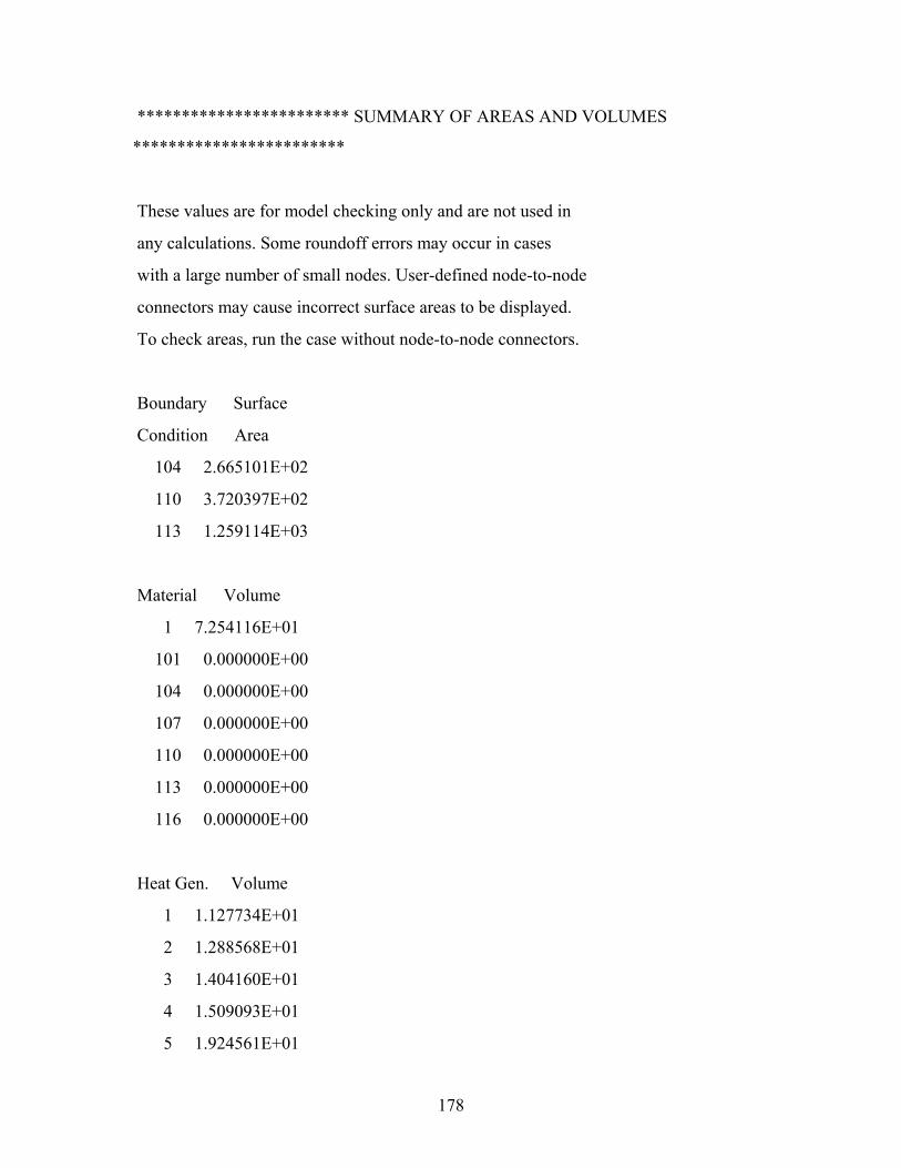
178
************************ SUMMARY OF AREAS AND VOLUMES
************************
These values are for model checking only and are not used in
any calculations. Some roundoff errors may occur in cases
with a large number of small nodes. User-defined node-to-node
connectors may cause incorrect surface areas to be displayed.
To check areas, run the case without node-to-node connectors.
Boundary Surface
Condition Area
104 2.665101E+02
110 3.720397E+02
113 1.259114E+03
Material Volume
1 7.254116E+01
101 0.000000E+00
104 0.000000E+00
107 0.000000E+00
110 0.000000E+00
113 0.000000E+00
116 0.000000E+00
Heat Gen. Volume
1 1.127734E+01
2 1.288568E+01
3 1.404160E+01
4 1.509093E+01
5 1.924561E+01
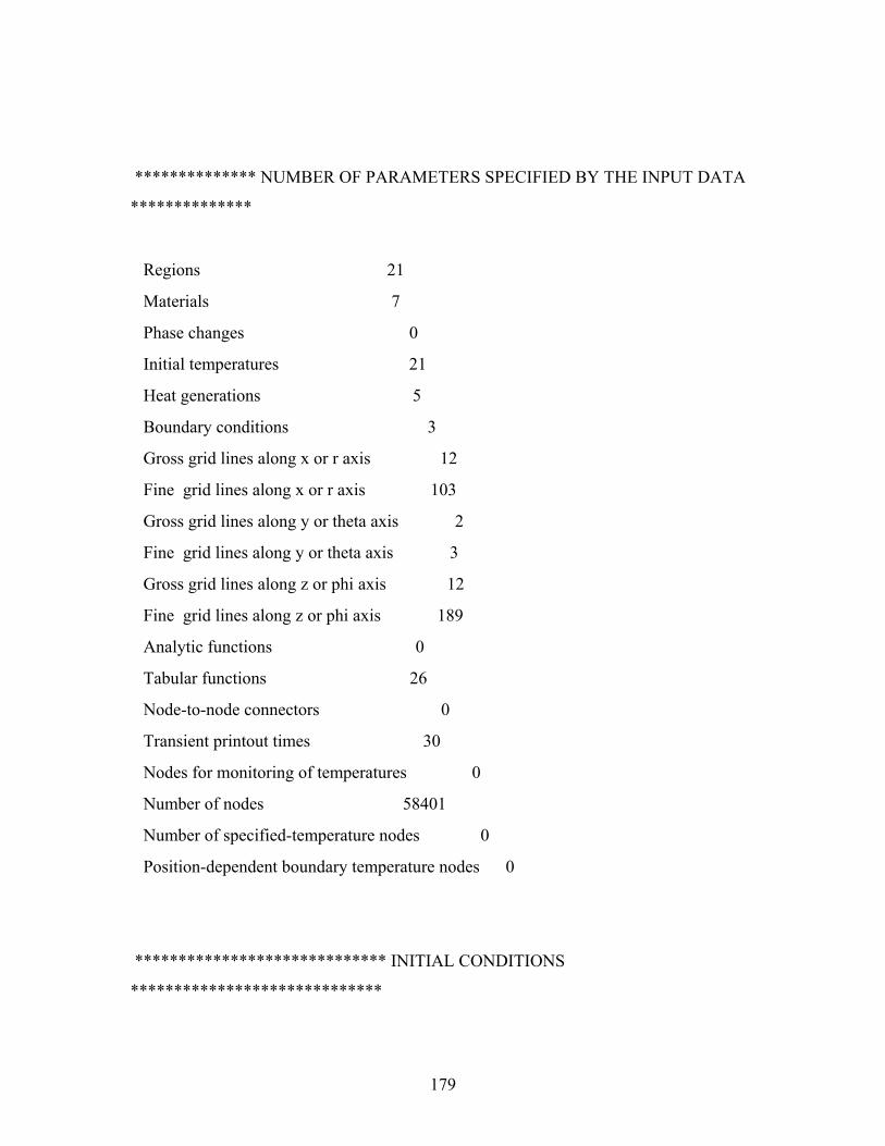
179
************** NUMBER OF PARAMETERS SPECIFIED BY THE INPUT DATA
**************
Regions 21
Materials 7
Phase changes 0
Initial temperatures 21
Heat generations 5
Boundary conditions 3
Gross grid lines along x or r axis 12
Fine grid lines along x or r axis 103
Gross grid lines along y or theta axis 2
Fine grid lines along y or theta axis 3
Gross grid lines along z or phi axis 12
Fine grid lines along z or phi axis 189
Analytic functions 0
Tabular functions 26
Node-to-node connectors 0
Transient printout times 30
Nodes for monitoring of temperatures 0
Number of nodes 58401
Number of specified-temperature nodes 0
Position-dependent boundary temperature nodes 0
***************************** INITIAL CONDITIONS
*****************************
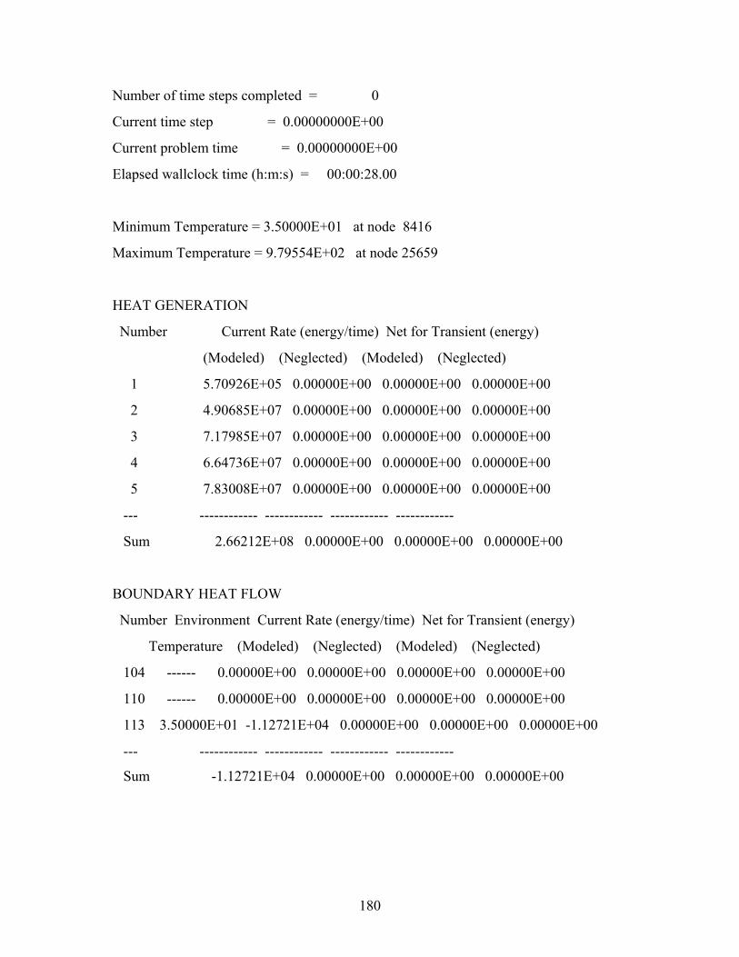
180
Number of time steps completed = 0
Current time step = 0.00000000E+00
Current problem time = 0.00000000E+00
Elapsed wallclock time (h:m:s) = 00:00:28.00
Minimum Temperature = 3.50000E+01 at node 8416
Maximum Temperature = 9.79554E+02 at node 25659
HEAT GENERATION
Number Current Rate (energy/time) Net for Transient (energy)
(Modeled) (Neglected) (Modeled) (Neglected)
1 5.70926E+05 0.00000E+00 0.00000E+00 0.00000E+00
2 4.90685E+07 0.00000E+00 0.00000E+00 0.00000E+00
3 7.17985E+07 0.00000E+00 0.00000E+00 0.00000E+00
4 6.64736E+07 0.00000E+00 0.00000E+00 0.00000E+00
5 7.83008E+07 0.00000E+00 0.00000E+00 0.00000E+00
--- ------------ ------------ ------------ ------------
Sum 2.66212E+08 0.00000E+00 0.00000E+00 0.00000E+00
BOUNDARY HEAT FLOW
Number Environment Current Rate (energy/time) Net for Transient (energy)
Temperature (Modeled) (Neglected) (Modeled) (Neglected)
104 ------ 0.00000E+00 0.00000E+00 0.00000E+00 0.00000E+00
110 ------ 0.00000E+00 0.00000E+00 0.00000E+00 0.00000E+00
113 3.50000E+01 -1.12721E+04 0.00000E+00 0.00000E+00 0.00000E+00
--- ------------ ------------ ------------ ------------
Sum -1.12721E+04 0.00000E+00 0.00000E+00 0.00000E+00
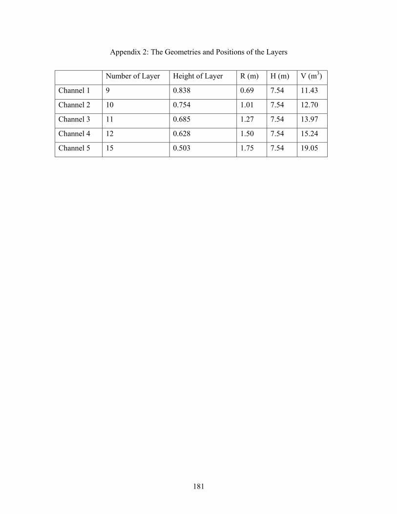
181
Appendix 2: The Geometries and Positions of the Layers
Number of Layer Height of Layer R (m) H (m) V (m3)
Channel 1 9 0.838 0.69 7.54 11.43
Channel 2 10 0.754 1.01 7.54 12.70
Channel 3 11 0.685 1.27 7.54 13.97
Channel 4 12 0.628 1.50 7.54 15.24
Channel 5 15 0.503 1.75 7.54 19.05
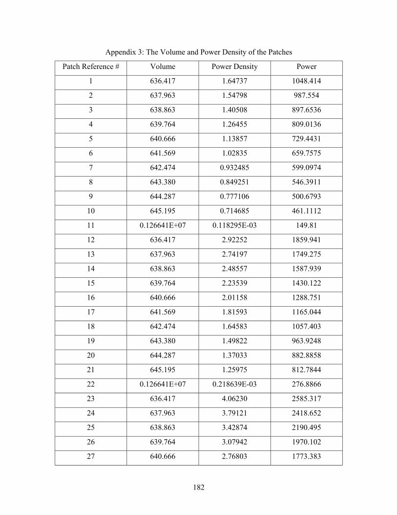
182
Appendix 3: The Volume and Power Density of the Patches
Patch Reference # Volume Power Density Power
1 636.417 1.64737 1048.414
2 637.963 1.54798 987.554
3 638.863 1.40508 897.6536
4 639.764 1.26455 809.0136
5 640.666 1.13857 729.4431
6 641.569 1.02835 659.7575
7 642.474 0.932485 599.0974
8 643.380 0.849251 546.3911
9 644.287 0.777106 500.6793
10 645.195 0.714685 461.1112
11 0.126641E+07 0.118295E-03 149.81
12 636.417 2.92252 1859.941
13 637.963 2.74197 1749.275
14 638.863 2.48557 1587.939
15 639.764 2.23539 1430.122
16 640.666 2.01158 1288.751
17 641.569 1.81593 1165.044
18 642.474 1.64583 1057.403
19 643.380 1.49822 963.9248
20 644.287 1.37033 882.8858
21 645.195 1.25975 812.7844
22 0.126641E+07 0.218639E-03 276.8866
23 636.417 4.06230 2585.317
24 637.963 3.79121 2418.652
25 638.863 3.42874 2190.495
26 639.764 3.07942 1970.102
27 640.666 2.76803 1773.383
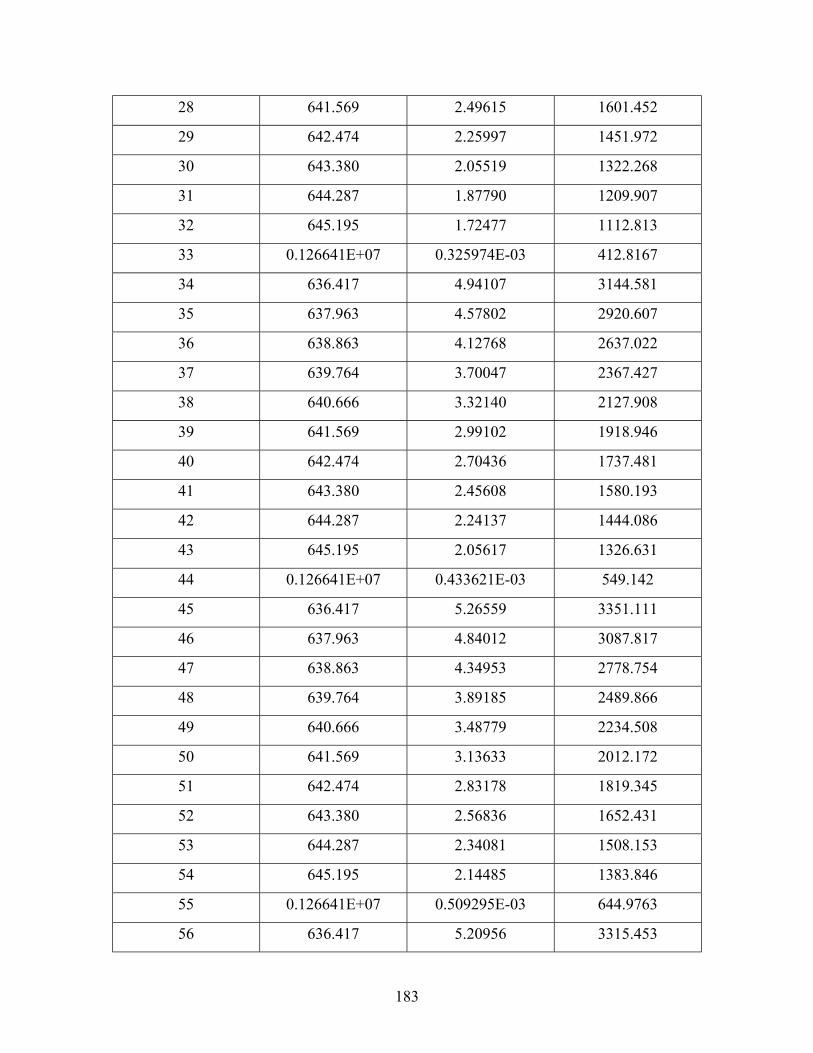
183
28 641.569 2.49615 1601.452
29 642.474 2.25997 1451.972
30 643.380 2.05519 1322.268
31 644.287 1.87790 1209.907
32 645.195 1.72477 1112.813
33 0.126641E+07 0.325974E-03 412.8167
34 636.417 4.94107 3144.581
35 637.963 4.57802 2920.607
36 638.863 4.12768 2637.022
37 639.764 3.70047 2367.427
38 640.666 3.32140 2127.908
39 641.569 2.99102 1918.946
40 642.474 2.70436 1737.481
41 643.380 2.45608 1580.193
42 644.287 2.24137 1444.086
43 645.195 2.05617 1326.631
44 0.126641E+07 0.433621E-03 549.142
45 636.417 5.26559 3351.111
46 637.963 4.84012 3087.817
47 638.863 4.34953 2778.754
48 639.764 3.89185 2489.866
49 640.666 3.48779 2234.508
50 641.569 3.13633 2012.172
51 642.474 2.83178 1819.345
52 643.380 2.56836 1652.431
53 644.287 2.34081 1508.153
54 645.195 2.14485 1383.846
55 0.126641E+07 0.509295E-03 644.9763
56 636.417 5.20956 3315.453
184
57 637.963 4.75235 3031.823
58 638.863 4.25717 2719.748
59 639.764 3.80232 2432.587
60 640.666 3.40270 2179.994
61 641.569 3.05578 1960.494
62 642.474 2.75558 1770.389
63 643.380 2.49624 1606.031
64 644.287 2.27249 1464.136
65 645.195 2.08009 1342.064
66 0.126641E+07 0.552767E-03 700.0297
67 636.417 4.80058 3055.171
68 637.963 4.35092 2775.726
69 638.863 3.88728 2483.439
70 639.764 3.46689 2217.991
71 640.666 3.09906 1985.462
72 641.569 2.78028 1783.741
73 642.474 2.50475 1609.237
74 643.380 2.26701 1458.549
75 644.287 2.06211 1328.591
76 645.195 1.88616 1216.941
77 0.126641E+07 0.553058E-03 700.3982
78 636.417 4.19310 2668.56
79 637.963 3.78096 2412.113
80 638.863 3.37131 2153.805
81 639.764 3.00363 1921.614
82 640.666 2.68294 1718.868
83 641.569 2.40538 1543.217
84 642.474 2.16572 1391.419
85 643.380 1.95913 1260.465
185
86 644.287 1.78124 1147.63
87 645.195 1.62865 1050.797
88 0.126641E+07 0.518122E-03 656.1549
89 636.417 3.35976 2138.208
90 637.963 3.00380 1916.313
91 638.863 2.66510 1702.634
92 639.764 2.36541 1513.304
93 640.666 2.10555 1348.954
94 641.569 1.88135 1207.016
95 642.474 1.68822 1084.637
96 643.380 1.52209 979.2823
97 644.287 1.37930 888.6651
98 645.195 1.25704 811.0359
99 0.126641E+07 0.426139E-03 539.6667
100 63641.7 1.21962 77618.69
101 63729.4 1.14527 72987.37
102 63819.3 1.03920 66321.02
103 63909.3 0.935082 59760.44
104 63999.4 0.841824 53876.23
105 64089.6 0.760268 48725.27
106 64180.0 0.689345 44242.16
107 64270.5 0.627777 40347.54
108 64361.1 0.574417 36970.11
109 64451.9 0.528252 34046.85
110 632370. 0.885165E-04 55.97518
111 63641.7 2.11031 134303.7
112 63729.4 1.98145 126276.6
113 63819.3 1.79706 114687.1
114 63909.3 1.61694 103337.5

186
115 63999.4 1.45579 93169.69
116 64089.6 1.31491 84272.06
117 64180.0 1.19243 76530.16
118 64270.5 1.08612 69805.48
119 64361.1 0.994009 63975.51
120 64451.9 0.914352 58931.72
121 632370. 0.161054E-03 101.8457
122 63641.7 3.01806 192074.5
123 63729.4 2.82567 180078.3
124 63819.3 2.56048 163408
125 63909.3 2.30337 147206.8
126 63999.4 2.07378 132720.7
127 64089.6 1.87319 120052
128 64180.0 1.69885 109032.2
129 64270.5 1.54760 99465.03
130 64361.1 1.41659 91173.29
131 64451.9 1.30338 84005.32
132 632370. 0.251238E-03 158.8754
133 63641.7 3.76357 239520
134 63729.4 3.50792 223557.6
135 63819.3 3.17444 202590.5
136 63909.3 2.85461 182436.1
137 63999.4 2.56986 164469.5
138 64089.6 2.32133 148773.1
139 64180.0 2.10547 135129.1
140 64270.5 1.91833 123292
141 64361.1 1.75631 113038
142 64451.9 1.61643 104182
143 632370. 0.350372E-03 221.5647
187
144 63641.7 4.11832 262096.9
145 63729.4 3.81831 243338.6
146 63819.3 3.44989 220169.6
147 63909.3 3.10102 198184
148 63999.4 2.79154 178656.9
149 64089.6 2.52179 161620.5
150 64180.0 2.28769 146823.9
151 64270.5 2.08491 133998.2
152 64361.1 1.90948 122896.2
153 64451.9 1.75817 113317.4
154 632370. 0.432698E-03 273.6252
155 63641.7 4.16190 264870.4
156 63729.4 3.83769 244573.7
157 63819.3 3.46173 220925.2
158 63909.3 3.11034 198779.7
159 63999.4 2.79985 179188.7
160 64089.6 2.52961 162121.7
161 64180.0 2.29532 147313.6
162 64270.5 2.09255 134489.2
163 64361.1 1.91727 123397.6
164 64451.9 1.76626 113838.8
165 632370. 0.490028E-03 309.879
166 63641.7 3.88282 247109.3
167 63729.4 3.56264 227044.9
168 63819.3 3.20902 204797.4
169 63909.3 2.88242 184213.4
170 63999.4 2.59486 166069.5
171 64089.6 2.34495 150286.9
172 64180.0 2.12847 136605.2
188
173 64270.5 1.94129 124767.7
174 64361.1 1.77961 114537.7
175 64451.9 1.64046 105730.8
176 632370. 0.504995E-03 319.3437
177 63641.7 3.39165 215850.4
178 63729.4 3.09928 197515.3
179 63819.3 2.78858 177965.2
180 63909.3 2.50444 160057
181 63999.4 2.25505 144321.8
182 64089.6 2.03856 130650.5
183 64180.0 1.85120 118810
184 64270.5 1.68931 108572.8
185 64361.1 1.54957 99732.03
186 64451.9 1.42941 92128.19
187 632370. 0.479257E-03 303.0677
188 63641.7 2.73429 174014.9
189 63729.4 2.50194 159447.1
190 63819.3 2.25678 144026.1
191 63909.3 2.03258 129900.8
192 63999.4 1.83553 117472.8
193 64089.6 1.66427 106662.4
194 64180.0 1.51592 97291.75
195 64270.5 1.38767 89186.24
196 64361.1 1.27691 82183.33
197 64451.9 1.18165 76159.59
198 632370. 0.425527E-03 269.0905
199 63641.7 2.31375 147251
200 63729.4 2.09068 133237.8
201 63819.3 1.87113 119414.2
189
202 63909.3 1.67486 107039.1
203 63999.4 1.50402 96256.38
204 64089.6 1.35630 86924.72
205 64180.0 1.22879 78863.74
206 64270.5 1.11888 71910.98
207 64361.1 1.02419 65918
208 64451.9 0.942926 60773.37
209 632370. 0.352777E-03 223.0856
210 127283. 0.772045 98268.2
211 127463. 0.731902 93290.42
212 127643. 0.667869 85248.8
213 127823. 0.603477 77138.24
214 128003. 0.545264 69795.43
215 128184. 0.494125 63338.92
216 128365. 0.449533 57704.3
217 128545. 0.410750 52799.86
218 128727. 0.377086 48541.15
219 120779. 0.347927 42022.28
220 1.00000 0.567821E-04 5.68E-05
221 127283. 1.29699 165084.8
222 127463. 1.23225 157066.3
223 127643. 1.12556 143669.9
224 127823. 1.01826 130157
225 128003. 0.921163 117911.6
226 128184. 0.835786 107134.4
227 128365. 0.761277 97721.32
228 128545. 0.696436 89523.37
229 128727. 0.640125 82401.37
230 120779. 0.591340 71421.45
190
231 1.00000 0.100438E-03 0.0001
232 127283. 1.87058 238093
233 127463. 1.77864 226710.8
234 127643. 1.62718 207698.1
235 127823. 1.47474 188505.7
236 128003. 1.33658 171086.2
237 128184. 1.21489 155729.5
238 128365. 1.10856 142300.3
239 128545. 1.01594 130594
240 128727. 0.935441 120416.5
241 120779. 0.865676 104555.5
242 1.00000 0.158710E-03 0.000159
243 127283. 2.39048 304267.5
244 127463. 2.27159 289543.7
245 127643. 2.08106 265632.7
246 127823. 1.88979 241558.6
247 128003. 1.71629 219690.3
248 128184. 1.56325 200383.6
249 128365. 1.42936 183479.8
250 128545. 1.31261 168729.5
251 128727. 1.21106 155896.1
252 120779. 1.12303 135638.4
253 1.00000 0.229082E-03 0.000229
254 127283. 2.59236 329963.4
255 127463. 2.45830 313342.3
256 127643. 2.25420 287732.9
257 127823. 2.05072 262129.2
258 128003. 1.86622 238881.8
259 128184. 1.70332 218338.4
191
260 128365. 1.56066 200334.1
261 128545. 1.43617 184612.5
262 128727. 1.32781 170925
263 120779. 1.23386 149024.4
264 1.00000 0.284304E-03 0.000284
265 127283. 2.62063 333561.6
266 127463. 2.47776 315822.7
267 127643. 2.27314 290150.4
268 127823. 2.07112 264736.8
269 128003. 1.88821 241696.5
270 128184. 1.72665 221328.9
271 128365. 1.58505 203464.9
272 128545. 1.46142 187858.2
273 128727. 1.35377 174266.8
274 120779. 1.26043 152233.5
275 1.00000 0.326439E-03 0.000326
276 127283. 2.51078 319579.6
277 127463. 2.36631 301617
278 127643. 2.17138 277161.5
279 127823. 1.98093 253208.4
280 128003. 1.80885 231538.2
281 128184. 1.65685 212381.7
282 128365. 1.52356 195571.8
283 128545. 1.40715 180882.1
284 128727. 1.30575 168085.3
285 120779. 1.21784 147089.5
286 1.00000 0.349316E-03 0.000349
287 127283. 2.30211 293019.5
288 127463. 2.16290 275689.7
192
289 127643. 1.98481 253347.1
290 127823. 1.81258 231689.4
291 128003. 1.65730 212139.4
292 128184. 1.52016 194860.2
293 128365. 1.39989 179696.9
294 128545. 1.29482 166442.6
295 128727. 1.20328 154894.6
296 120779. 1.12392 135745.9
297 1.00000 0.350881E-03 0.000351
298 127283. 2.01223 256122.7
299 127463. 1.88502 240270.3
300 127643. 1.72953 220762.4
301 127823. 1.58061 202038.3
302 128003. 1.44666 185176.8
303 128184. 1.32840 170279.6
304 128365. 1.22468 157206
305 128545. 1.13407 145779
306 128727. 1.05512 135822.4
307 120779. 0.986694 119171.9
308 1.00000 0.329903E-03 0.00033
309 127283. 1.75233 223041.8
310 127463. 1.63562 208481
311 127643. 1.49932 191377.7
312 127823. 1.37018 175140.5
313 128003. 1.25441 160568.2
314 128184. 1.15230 147706.4
315 128365. 1.06279 136425
316 128545. 0.984622 126568.2
317 128727. 0.916527 117981.8
193
318 120779. 0.857525 103571
319 1.00000 0.302584E-03 0.000303
320 127283. 1.43986 183269.7
321 127463. 1.34110 170940.6
322 127643. 1.22904 156878.4
323 127823. 1.12359 143620.6
324 128003. 1.02924 131745.8
325 128184. 0.946072 121271.3
326 128365. 0.873174 112085
327 128545. 0.809520 104059.7
328 128727. 0.754076 97069.94
329 120779. 0.706032 85273.84
330 1.00000 0.260114E-03 0.00026
331 127283. 0.654751 83338.67
332 127463. 0.620700 79116.28
333 127643. 0.566380 72294.44
334 127823. 0.511756 65414.19
335 128003. 0.462379 59185.9
336 128184. 0.419004 53709.61
337 128365. 0.381183 48930.56
338 128545. 0.348290 44770.94
339 128727. 0.319741 41159.3
340 120781. 0.295011 35631.72
341 1.00000 0.481541E-04 4.82E-05
342 127283. 1.06810 135951
343 127463. 1.01511 129389
344 127643. 0.927266 118359
345 127823. 0.838845 107223.7
346 128003. 0.758828 97132.26
194
347 128184. 0.688469 88250.71
348 128365. 0.627073 80494.23
349 128545. 0.573645 73739.2
350 128727. 0.527247 67870.92
351 120781. 0.487050 58826.39
352 1.00000 0.822150E-04 8.22E-05
353 127283. 1.60928 204834
354 127463. 1.53182 195250.4
355 127643. 1.40180 178930
356 127823. 1.27054 162404.2
357 128003. 1.15150 147395.5
358 128184. 1.04664 134162.5
359 128365. 0.955018 122590.9
360 128545. 0.875208 112503.6
361 128727. 0.805843 103733.8
362 120781. 0.745725 90069.41
363 1.00000 0.134187E-03 0.000134
364 127283. 2.13367 271579.9
365 127463. 2.03120 258902.8
366 127643. 1.86177 237641.9
367 127823. 1.69084 216128.2
368 128003. 1.53558 196558.8
369 128184. 1.39860 179278.1
370 128365. 1.27874 164145.5
371 128545. 1.17424 150942.7
372 128727. 1.08333 139453.8
373 120781. 1.00452 121326.9
374 1.00000 0.198727E-03 0.000199
375 127283. 2.33843 297642.4
195
376 127463. 2.22265 283305.6
377 127643. 2.03938 260312.6
378 127823. 1.85546 237170.5
379 128003. 1.68841 216121.5
380 128184. 1.54086 197513.6
381 128365. 1.41162 181202.6
382 128545. 1.29884 166959.4
383 128727. 1.20066 154557.4
384 120781. 1.11554 134736
385 1.00000 0.247238E-03 0.000247
386 127283. 2.36029 300424.8
387 127463. 2.23764 285216.3
388 127643. 2.05428 262214.5
389 127823. 1.87182 239261.6
390 128003. 1.70627 218407.7
391 128184. 1.55998 199964.5
392 128365. 1.43175 183786.6
393 128545. 1.31978 169651.1
394 128727. 1.22226 157337.9
395 120781. 1.13771 137413.8
396 1.00000 0.282083E-03 0.000282
397 127283. 2.22271 282913.2
398 127463. 2.10106 267807.4
399 127643. 1.92940 246274.4
400 127823. 1.76021 224995.3
401 128003. 1.60698 205698.3
402 128184. 1.47154 188627.9
403 128365. 1.35277 173648.3
404 128545. 1.24903 160556.6
196
405 128727. 1.15864 149148.3
406 120781. 1.08028 130477.3
407 1.00000 0.295971E-03 0.000296
408 127283. 2.02179 257339.5
409 127463. 1.90575 242912.6
410 127643. 1.75023 223404.6
411 127823. 1.59837 204308.4
412 128003. 1.46112 187027.7
413 128184. 1.33981 171742.2
414 128365. 1.23339 158324.1
415 128545. 1.14042 146595.3
416 128727. 1.05940 136373.4
417 120781. 0.989158 119471.5
418 1.00000 0.294586E-03 0.000295
419 127283. 1.75504 223386.8
420 127463. 1.64969 210274.4
421 127643. 1.51483 193357.4
422 127823. 1.38436 176953
423 128003. 1.26669 162140.1
424 128184. 1.16272 149042.1
425 128365. 1.07152 137545.7
426 128545. 0.991838 127495.8
427 128727. 0.922391 118736.6
428 120781. 0.862188 104135.9
429 1.00000 0.274875E-03 0.000275
430 127283. 1.55264 197624.7
431 127463. 1.45408 185341.4
432 127643. 1.33389 170261.7
433 127823. 1.21889 155802.2
197
434 128003. 1.11552 142789.9
435 128184. 1.02429 131297.6
436 128365. 0.944301 121215.2
437 128545. 0.874433 112404
438 128727. 0.813554 104726.4
439 120781. 0.760792 91889.22
440 1.00000 0.256112E-03 0.000256
441 127283. 1.32065 168096.3
442 127463. 1.23368 157248.6
443 127643. 1.13114 144382.1
444 127823. 1.03380 132143.4
445 128003. 0.946510 121156.1
446 128184. 0.869527 111459.4
447 128365. 0.802047 102954.8
448 128545. 0.743117 95523.97
449 128727. 0.691780 89050.76
450 120781. 0.647287 78179.97
451 1.00000 0.228017E-03 0.000228
452 127283. 1.17948 150127.8
453 127463. 1.10029 140246.3
454 127643. 1.00889 128777.7
455 127823. 0.922547 117922.7
456 128003. 0.845208 108189.2
457 128184. 0.777019 99601.4
458 128365. 0.717248 92069.54
459 128545. 0.665050 85488.85
460 128727. 0.619579 79756.55
461 120781. 0.580159 70072.18
462 1.00000 0.212031E-03 0.000212
198
463 127283. 0.607095 77272.87
464 127463. 0.575864 73401.35
465 127643. 0.525627 67092.61
466 127823. 0.475027 60719.38
467 128003. 0.429260 54946.57
468 128184. 0.389046 49869.47
469 128365. 0.353976 45438.13
470 128545. 0.323471 41580.58
471 128727. 0.296992 38230.89
472 120784. 0.274054 33101.34
473 1.00000 0.444227E-04 4.44E-05
474 127283. 1.00670 128135.8
475 127463. 0.957593 122057.7
476 127643. 0.875062 111695.5
477 127823. 0.791792 101209.2
478 128003. 0.716373 91697.89
479 128184. 0.650034 83323.96
480 128365. 0.592132 76009.02
481 128545. 0.541738 69637.71
482 128727. 0.497969 64102.06
483 120784. 0.460045 55566.08
484 1.00000 0.765580E-04 7.66E-05
485 127283. 1.62555 206904.9
486 127463. 1.54892 197430
487 127643. 1.41798 180995.2
488 127823. 1.28541 164305
489 128003. 1.16505 149129.9
490 128184. 1.05898 135744.3
491 128365. 0.966280 124036.5
199
492 128545. 0.885512 113828.1
493 128727. 0.815304 104951.6
494 120784. 0.754449 91125.37
495 1.00000 0.132430E-03 0.000132
496 127283. 2.18792 278485
497 127463. 2.08458 265706.8
498 127643. 1.91107 243934.7
499 127823. 1.73553 221840.7
500 128003. 1.57593 201723.8
501 128184. 1.43505 183950.4
502 128365. 1.31175 168382.8
503 128545. 1.20422 154796.5
504 128727. 1.11067 142973.2
505 120784. 1.02956 124354.4
506 1.00000 0.196836E-03 0.000197
507 127283. 2.39048 304267.5
508 127463. 2.27319 289747.6
509 127643. 2.08554 266204.6
510 127823. 1.89682 242457.2
511 128003. 1.72527 220839.7
512 128184. 1.57368 201720.6
513 128365. 1.44087 184957.3
514 128545. 1.32496 170317
515 128727. 1.22404 157567
516 120784. 1.13654 137275.8
517 1.00000 0.241441E-03 0.000241
518 127283. 2.38145 303118.1
519 127463. 2.25793 287802.5
520 127643. 2.07204 264481.4

200
521 127823. 1.88677 241172.6
522 128003. 1.71858 219983.4
523 128184. 1.56990 201236.1
524 128365. 1.43953 184785.3
525 128545. 1.32569 170410.8
526 128727. 1.22653 157887.5
527 120784. 1.14056 137761.4
528 1.00000 0.269234E-03 0.000269
529 127283. 2.22953 283781.3
530 127463. 2.10704 268569.6
531 127643. 1.93347 246793.9
532 127823. 1.76222 225252.2
533 128003. 1.60705 205707.2
534 128184. 1.46985 188411.3
535 128365. 1.34951 173229.9
536 128545. 1.24439 159960.1
537 128727. 1.15280 148396.5
538 120784. 1.07339 129648.3
539 1.00000 0.278410E-03 0.000278
540 127283. 1.99915 254457.8
541 127463. 1.88343 240067.6
542 127643. 1.72796 220562
543 127823. 1.57604 201454.2
544 128003. 1.43867 184154.1
545 128184. 1.31722 168846.5
546 128365. 1.21066 155406.4
547 128545. 1.11756 143656.8
548 128727. 1.03643 133416.5
549 120784. 0.966104 116689.9
201
550 1.00000 0.271202E-03 0.000271
551 127283. 1.73473 220801.6
552 127463. 1.62956 207708.6
553 127643. 1.49456 190770.1
554 127823. 1.36381 174326.3
555 128003. 1.24583 159470
556 128184. 1.14156 146329.7
557 128365. 1.05007 134792.2
558 128545. 0.970125 124704.7
559 128727. 0.900457 115913.1
560 120784. 0.840068 101466.8
561 1.00000 0.251462E-03 0.000251
562 127283. 1.50277 191277.1
563 127463. 1.40607 179221.9
564 127643. 1.28793 164395.2
565 127823. 1.17481 150167.7
566 128003. 1.07308 137357.5
567 128184. 0.983284 126041.3
568 128365. 0.904533 116110.4
569 128545. 0.835748 107431.2
570 128727. 0.775818 99868.72
571 120784. 0.723885 87433.73
572 1.00000 0.228136E-03 0.000228
573 127283. 1.29819 165237.5
574 127463. 1.21135 154402.3
575 127643. 1.10878 141528
576 127823. 1.01133 129271.2
577 128003. 0.923914 118263.8
578 128184. 0.846797 108545.8
202
579 128365. 0.779191 100020.9
580 128545. 0.720154 92572.2
581 128727. 0.668728 86083.35
582 120784. 0.624169 75389.63
583 1.00000 0.205352E-03 0.000205
584 127283. 1.18684 151064.6
585 127463. 1.10508 140856.8
586 127643. 1.01099 129045.8
587 127823. 0.922165 117873.9
588 128003. 0.842620 107857.9
589 128184. 0.772494 99021.37
590 128365. 0.711032 91271.62
591 128545. 0.657369 84501.5
592 128727. 0.610634 78605.08
593 120784. 0.570134 68863.07
594 1.00000 0.194467E-03 0.000194
595 127283. 1.08819 138508.1
596 127463. 1.01152 128931.4
597 127643. 0.925078 118079.7
598 127823. 0.843889 107868.4
599 128003. 0.771287 98727.05
600 128184. 0.707308 90665.57
601 128365. 0.651246 83597.19
602 128545. 0.602303 77423.04
603 128727. 0.559687 72046.83
604 120784. 0.522747 63139.47
605 1.00000 0.183931E-03 0.000184
606 127283. 1.08393 137965.9
607 127463. 1.00620 128253.3
203
608 127643. 0.920028 117435.1
609 127823. 0.839416 107296.7
610 128003. 0.767410 98230.78
611 128184. 0.703973 90238.08
612 128365. 0.648390 83230.58
613 128545. 0.599867 77109.9
614 128727. 0.557625 71781.39
615 120784. 0.520994 62927.74
616 1.00000 0.188185E-03 0.000188
617 127283. 1.10942 141210.3
618 127463. 1.02876 131128.8
619 127643. 0.940554 120055.1
620 127823. 0.858321 109713.2
621 128003. 0.784925 100472.8
622 128184. 0.720273 92327.47
623 128365. 0.663624 85186.09
624 128545. 0.614168 78948.23
625 128727. 0.571123 73518.95
626 120784. 0.533773 64471.24
627 1.00000 0.197166E-03 0.000197
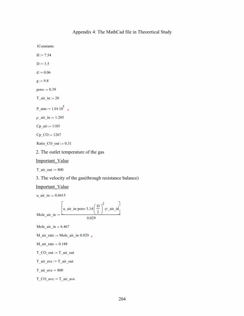
204
Appendix 4: The MathCad file in Theoretical Study
1Constants
H 7.54:=
D 3.5:=
d 0.06:=
g 9.8:=
poro 0.39:=
T_air_in 20:=
P_atm 1.01 105⋅:= *
ρ_air_in 1.205:=
Cp_air 1185:=
Cp_CO 1267:=
Ratio_CO_out 0.31:=
2. The outlet temperature of the gas
Important_Value
T_air_out 800:=
3. The velocity of the gas(through resistance balance)
Important_Value
u_air_in 0.0415:=
Mole_air_inu_air_in poro⋅ 3.14⋅
D2
2⋅ ρ_air_in⋅
0.029:=
Mole_air_in 6.467=
M_air_rate Mole_air_in 0.029⋅:= *
M_air_rate 0.188=
T_CO_out T_air_out:=
T_air_ave T_air_out:=
T_air_ave 800=
T_CO_ave T_air_ave:=

205
T_CO_ave 800=
Cp_air_in 1005:=
Cp_out 1043 0.1435 T_air_out 27−( )⋅+[ ] 1 Ratio_CO_out−( )⋅ 1041 0.1494 T_air_out 27−( )⋅+[ ] Ratio_CO_out⋅+:=
Cp_out 1.155 103×=
Cp_aveCp_air_in Cp_out+( )
2:=
Cp_ave 1.08 103×=
k_N_ave 0.0267 5.13510 5−⋅ T_air_ave 27−( )⋅+:= *
k_N_ave 0.066=
k_O_ave 0.0274 5.8 105−
⋅ T_air_ave 27−( )⋅+:= *
k_N_ave 0.066=
k_CO_ave 0.026 5.8 10 5−⋅ T_CO_ave 27−( )⋅+:= *
k_CO_ave 0.071=
k_ave k_N_ave 1 Ratio_CO_out−( )⋅ k_O_aveRatio_CO_out
2⋅+ k_CO_ave
Ratio_CO_out2
⋅+:= *
k_ave 0.068=
ρ_CO_ave336.82
T_CO_ave 273+( ):= *
ρ_CO_ave 0.314=
ρ_CO_out336.82
T_CO_out 273+:=
ρ_CO_out 0.314=
ρ_N_ave341.4
T_CO_ave 273+( ):= *
ρ_N_ave 0.318=
ρ_N_out341.4
T_CO_out 273+:=
ρ_N_out 0.318=
ρ_O_ave389.7
T_CO_ave 273+( ):= *
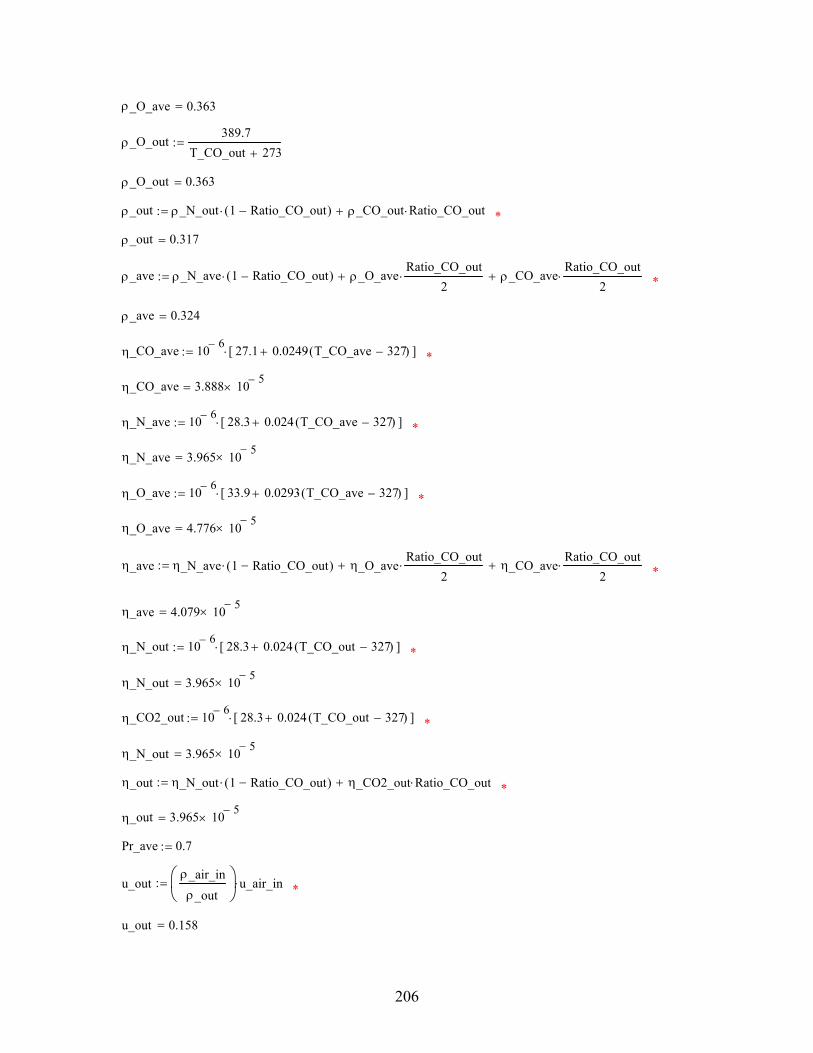
206
ρ_O_ave 0.363=
ρ_O_out389.7
T_CO_out 273+:=
ρ_O_out 0.363=
ρ_out ρ_N_out 1 Ratio_CO_out−( )⋅ ρ_CO_out Ratio_CO_out⋅+:= *
ρ_out 0.317=
ρ_ave ρ_N_ave 1 Ratio_CO_out−( )⋅ ρ_O_aveRatio_CO_out
2⋅+ ρ_CO_ave
Ratio_CO_out2
⋅+:= *
ρ_ave 0.324=
η_CO_ave 10 6− 27.1 0.0249 T_CO_ave 327−( )⋅+[ ]⋅:= *
η_CO_ave 3.888 10 5−×=
η_N_ave 10 6− 28.3 0.024 T_CO_ave 327−( )⋅+[ ]⋅:= *
η_N_ave 3.965 10 5−×=
η_O_ave 10 6− 33.9 0.0293 T_CO_ave 327−( )⋅+[ ]⋅:= *
η_O_ave 4.776 10 5−×=
η_ave η_N_ave 1 Ratio_CO_out−( )⋅ η_O_aveRatio_CO_out
2⋅+ η_CO_ave
Ratio_CO_out2
⋅+:= *
η_ave 4.079 10 5−×=
η_N_out 10 6− 28.3 0.024 T_CO_out 327−( )⋅+[ ]⋅:= *
η_N_out 3.965 10 5−×=
η_CO2_out 10 6− 28.3 0.024 T_CO_out 327−( )⋅+[ ]⋅:= *
η_N_out 3.965 10 5−×=
η_out η_N_out 1 Ratio_CO_out−( )⋅ η_CO2_out Ratio_CO_out⋅+:= *
η_out 3.965 10 5−×=
Pr_ave 0.7:=
u_outρ_air_inρ_out
u_air_in⋅:= *
u_out 0.158=
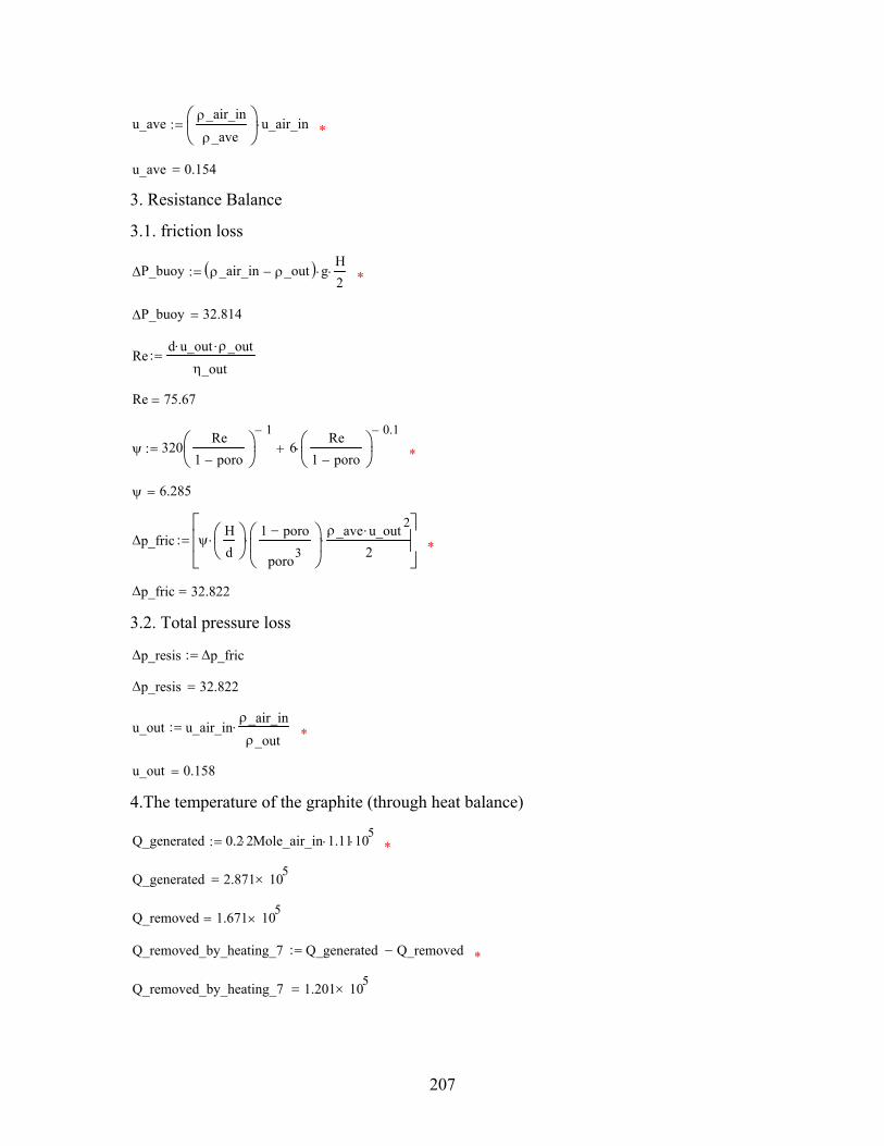
207
u_aveρ_air_in
ρ_ave
u_air_in⋅:= *
u_ave 0.154=
3. Resistance Balance
3.1. friction loss
∆P_buoy ρ_air_in ρ_out−( ) g⋅H2⋅:= *
∆P_buoy 32.814=
Red u_out⋅ ρ_out⋅
η_out:=
Re 75.67=
ψ 320Re
1 poro−
1−6
Re1 poro−
0.1−⋅+:= *
ψ 6.285=
∆p_fric ψHd
⋅1 poro−
poro3
⋅ρ_ave u_out 2⋅
2⋅
:= *
∆p_fric 32.822=
3.2. Total pressure loss
∆p_resis ∆p_fric:=
∆p_resis 32.822=
u_out u_air_inρ_air_inρ_out
⋅:= *
u_out 0.158=
4.The temperature of the graphite (through heat balance)
Q_generated 0.2 2⋅ Mole_air_in 1.11⋅ 105⋅:= *
Q_generated 2.871 105×=
Q_removed 1.671 105×=
Q_removed_by_heating_7 Q_generated Q_removed−:= *
Q_removed_by_heating_7 1.201 105×=
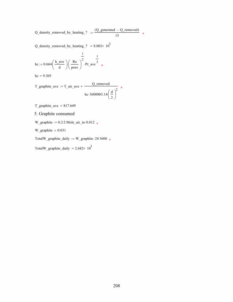
208
Q_density_removed_by_heating_7Q_generated Q_removed−( )
15:= *
Q_density_removed_by_heating_7 8.003 103×=
hc 0.664k_ave
d
⋅Re
poro
1
2⋅ Pr_ave
1
3⋅:= *
hc 9.305=
T_graphite_ave T_air_aveQ_removed
hc 360000⋅ 3.14⋅d2
2⋅
+:= *
T_graphite_ave 817.649=
5. Graphite consumed
W_graphite 0.2 2⋅ Mole_air_in⋅ 0.012⋅:= *
W_graphite 0.031=
TotalW_graphite_daily W_graphite 24⋅ 3600⋅:= *
TotalW_graphite_daily 2.682 103×=
209
Appendix 5: The Input for Non-Isothermal Experiment
FLUENT
Version: 3d, dp, segregated, spe2, lam, unsteady (3d, double precision, segregated, 2
species, laminar, unsteady)
Release: 6.0.20
Title:
Models
------
Model Settings
---------------------------------------------------------
Space 3D
Time Unsteady, 2nd-Order Implicit
Viscous Laminar
Heat Transfer Enabled
Solidification and Melting Disabled
Radiation None
Species Transport Non-Reacting (2 species)
Coupled Dispersed Phase Disabled
Pollutants Disabled
Soot Disabled
Boundary Conditions
-------------------
Zones
name id type
210
--------------------------------------
he-region 2 fluid
n_region 3 fluid
region01_outside 4 wall
region09_outside 5 wall
tank_region_wall 6 wall
region02_outside 7 wall
region08_outside 8 wall
region03_outside 9 wall
region07_outside 10 wall
region04_outside 11 wall
region06_outside 12 wall
region05_outside 13 wall
all_symmetry_faces 14 symmetry
default-interior 16 interior
all_symmetry_faces:001 1 symmetry
default-interior:015 15 interior
default-interior:017 17 interior
Boundary Conditions
he-region
Condition Value
-------------------------------------------------------------------------------------------------------
-------------------------
Material Name mixture-template
211
Specify source terms? no
Source Terms ((mass (inactive . #f) (constant . 0) (profile
)) (x-momentum (inactive . #f) (constant . 0) (profile )) (y-momentum (inactive . #f)
(constant . 0) (profile )) (z-momentum (inactive . #f) (const
nt . 0) (profile )) (species-0 (inactive . #f) (constant . 0) (profile )) (energy (inactive .
#f) (constant . 0) (profile )))
Specify fixed values? no
Local Coordinate System for Fixed Velocities no
Fixed Values ((x-velocity (constant . 0) (profile )) (y-
velocity (constant . 0) (profile )) (z-velocity (constant . 0) (profile )) (species-0
(profile udf he_profile) (constant . 0)) (temperature (constant .
291.14999) (profile )))
Motion Type 0
X-Velocity Of Zone 0
Y-Velocity Of Zone 0
Z-Velocity Of Zone 0
Rotation speed 0

212
X-Origin of Rotation-Axis 0
Y-Origin of Rotation-Axis 0
Z-Origin of Rotation-Axis 0
X-Component of Rotation-Axis 0
Y-Component of Rotation-Axis 0
Z-Component of Rotation-Axis 1
Porous zone? no
Conical porous zone? no
X-Component of Direction-1 Vector 1
Y-Component of Direction-1 Vector 1
Z-Component of Direction-1 Vector 1
X-Component of Direction-2 Vector 0
Y-Component of Direction-2 Vector 1
Z-Component of Direction-2 Vector 0
X-Coordinate of Point on Cone Axis 1
213
Y-Coordinate of Point on Cone Axis 0
Z-Coordinate of Point on Cone Axis 0
Half Angle of Cone Relative to its Axis 0
Direction-1 Viscous Resistance 0
Direction-2 Viscous Resistance 0
Direction-3 Viscous Resistance 0
Direction-1 Inertial Resistance 0
Direction-2 Inertial Resistance 0
Direction-3 Inertial Resistance 0
C0 Coefficient for Power-Law 0
C1 Coefficient for Power-Law 0
Porosity 1
Solid Material Name aluminum
n_region
Condition Value
214
------------------------------------------------------------------------------------------------
-------------------------------------------------------------------------------------------------------
---------------------------------------------
-------------------------------------------------------------------------------------------------------
-------------------------
Material Name mixture-template
Specify source terms? no
Source Terms ((mass (inactive . #f) (constant . 0) (profile
)) (x-momentum (inactive . #f) (constant . 0) (profile )) (y-momentum (inactive . #f)
(constant . 0) (profile )) (z-momentum (inactive . #f) (const
nt . 0) (profile )) (species-0 (inactive . #f) (constant . 0) (profile )) (energy (inactive .
#f) (constant . 0) (profile )))
Specify fixed values? no
Local Coordinate System for Fixed Velocities no
Fixed Values ((x-velocity (constant . 0) (profile )) (y-
velocity (constant . 0) (profile )) (z-velocity (constant . 0) (profile )) (species-0
(profile udf he_profile) (constant . 0)) (temperature (constant .
291.14999) (profile )))
Motion Type 0
X-Velocity Of Zone 0
Y-Velocity Of Zone 0
Z-Velocity Of Zone 0
215
Rotation speed 0
X-Origin of Rotation-Axis 0
Y-Origin of Rotation-Axis 0
Z-Origin of Rotation-Axis 0
X-Component of Rotation-Axis 0
Y-Component of Rotation-Axis 0
Z-Component of Rotation-Axis 1
Porous zone? no
Conical porous zone? no
X-Component of Direction-1 Vector 1
Y-Component of Direction-1 Vector 1
Z-Component of Direction-1 Vector 1
X-Component of Direction-2 Vector 0
Y-Component of Direction-2 Vector 1
Z-Component of Direction-2 Vector 0
216
X-Coordinate of Point on Cone Axis 1
Y-Coordinate of Point on Cone Axis 0
Z-Coordinate of Point on Cone Axis 0
Half Angle of Cone Relative to its Axis 0
Direction-1 Viscous Resistance 0
Direction-2 Viscous Resistance 0
Direction-3 Viscous Resistance 0
Direction-1 Inertial Resistance 0
Direction-2 Inertial Resistance 0
Direction-3 Inertial Resistance 0
C0 Coefficient for Power-Law 0
C1 Coefficient for Power-Law 0
Porosity 1
Solid Material Name aluminum
region01_outside
Condition Value
217
-----------------------------------------------------------------------------------
Wall Thickness 0
Heat Generation Rate 0
Material Name aluminum
Thermal BC Type 0
Temperature 291.14999
Heat Flux 0
Convective Heat Transfer Coefficient 0
Free Stream Temperature 300
Enable shell conduction? no
Wall Motion 0
Shear Boundary Condition 0
Define wall motion relative to adjacent cell zone? yes
Apply a rotational velocity to this wall? no
Velocity Magnitude 0
X-Component of Wall Translation 1
Y-Component of Wall Translation 0
Z-Component of Wall Translation 0
Define wall velocity components? no
X-Component of Wall Translation 0
Y-Component of Wall Translation 0
Z-Component of Wall Translation 0
External Emissivity 1
External Radiation Temperature 300
(0)
(((constant . 0) (profile )))
Rotation Speed 0
X-Position of Rotation-Axis Origin 0
Y-Position of Rotation-Axis Origin 0
Z-Position of Rotation-Axis Origin 0
218
X-Component of Rotation-Axis Direction 0
Y-Component of Rotation-Axis Direction 0
Z-Component of Rotation-Axis Direction 1
X-component of shear stress 0
Y-component of shear stress 0
Z-component of shear stress 0
Surface tension gradient 0
region09_outside
Condition Value
-----------------------------------------------------------------------------------
Wall Thickness 0
Heat Generation Rate 0
Material Name aluminum
Thermal BC Type 0
Temperature 291.14999
Heat Flux 0
Convective Heat Transfer Coefficient 0
Free Stream Temperature 300
Enable shell conduction? no
Wall Motion 0
Shear Boundary Condition 0
Define wall motion relative to adjacent cell zone? yes
Apply a rotational velocity to this wall? no
Velocity Magnitude 0
X-Component of Wall Translation 1
Y-Component of Wall Translation 0
Z-Component of Wall Translation 0
Define wall velocity components? no
219
X-Component of Wall Translation 0
Y-Component of Wall Translation 0
Z-Component of Wall Translation 0
External Emissivity 1
External Radiation Temperature 300
(0)
(((constant . 0) (profile )))
Rotation Speed 0
X-Position of Rotation-Axis Origin 0
Y-Position of Rotation-Axis Origin 0
Z-Position of Rotation-Axis Origin 0
X-Component of Rotation-Axis Direction 0
Y-Component of Rotation-Axis Direction 0
Z-Component of Rotation-Axis Direction 1
X-component of shear stress 0
Y-component of shear stress 0
Z-component of shear stress 0
Surface tension gradient 0
tank_region_wall
Condition Value
-----------------------------------------------------------------------------------
Wall Thickness 0
Heat Generation Rate 0
Material Name aluminum
Thermal BC Type 0
Temperature 291.14999
Heat Flux 0
Convective Heat Transfer Coefficient 0
220
Free Stream Temperature 300
Enable shell conduction? no
Wall Motion 0
Shear Boundary Condition 0
Define wall motion relative to adjacent cell zone? yes
Apply a rotational velocity to this wall? no
Velocity Magnitude 0
X-Component of Wall Translation 1
Y-Component of Wall Translation 0
Z-Component of Wall Translation 0
Define wall velocity components? no
X-Component of Wall Translation 0
Y-Component of Wall Translation 0
Z-Component of Wall Translation 0
External Emissivity 1
External Radiation Temperature 300
(0)
(((constant . 0) (profile )))
Rotation Speed 0
X-Position of Rotation-Axis Origin 0
Y-Position of Rotation-Axis Origin 0
Z-Position of Rotation-Axis Origin 0
X-Component of Rotation-Axis Direction 0
Y-Component of Rotation-Axis Direction 0
Z-Component of Rotation-Axis Direction 1
X-component of shear stress 0
Y-component of shear stress 0
Z-component of shear stress 0
Surface tension gradient 0
221
region02_outside
Condition Value
-----------------------------------------------------------------------------------
Wall Thickness 0
Heat Generation Rate 0
Material Name aluminum
Thermal BC Type 0
Temperature 291.14999
Heat Flux 0
Convective Heat Transfer Coefficient 0
Free Stream Temperature 300
Enable shell conduction? no
Wall Motion 0
Shear Boundary Condition 0
Define wall motion relative to adjacent cell zone? yes
Apply a rotational velocity to this wall? no
Velocity Magnitude 0
X-Component of Wall Translation 1
Y-Component of Wall Translation 0
Z-Component of Wall Translation 0
Define wall velocity components? no
X-Component of Wall Translation 0
Y-Component of Wall Translation 0
Z-Component of Wall Translation 0
External Emissivity 1
External Radiation Temperature 300
(0)
(((constant . 0) (profile )))
Rotation Speed 0
222
X-Position of Rotation-Axis Origin 0
Y-Position of Rotation-Axis Origin 0
Z-Position of Rotation-Axis Origin 0
X-Component of Rotation-Axis Direction 0
Y-Component of Rotation-Axis Direction 0
Z-Component of Rotation-Axis Direction 1
X-component of shear stress 0
Y-component of shear stress 0
Z-component of shear stress 0
Surface tension gradient 0
region08_outside
Condition Value
-----------------------------------------------------------------------------------
Wall Thickness 0
Heat Generation Rate 0
Material Name aluminum
Thermal BC Type 0
Temperature 291.14999
Heat Flux 0
Convective Heat Transfer Coefficient 0
Free Stream Temperature 300
Enable shell conduction? no
Wall Motion 0
Shear Boundary Condition 0
Define wall motion relative to adjacent cell zone? yes
Apply a rotational velocity to this wall? no
Velocity Magnitude 0
X-Component of Wall Translation 1
223
Y-Component of Wall Translation 0
Z-Component of Wall Translation 0
Define wall velocity components? no
X-Component of Wall Translation 0
Y-Component of Wall Translation 0
Z-Component of Wall Translation 0
External Emissivity 1
External Radiation Temperature 300
(0)
(((constant . 0) (profile )))
Rotation Speed 0
X-Position of Rotation-Axis Origin 0
Y-Position of Rotation-Axis Origin 0
Z-Position of Rotation-Axis Origin 0
X-Component of Rotation-Axis Direction 0
Y-Component of Rotation-Axis Direction 0
Z-Component of Rotation-Axis Direction 1
X-component of shear stress 0
Y-component of shear stress 0
Z-component of shear stress 0
Surface tension gradient 0
region03_outside
Condition Value
-----------------------------------------------------------------------------------
Wall Thickness 0
Heat Generation Rate 0
Material Name aluminum
Thermal BC Type 0
224
Temperature 291.14999
Heat Flux 0
Convective Heat Transfer Coefficient 0
Free Stream Temperature 300
Enable shell conduction? no
Wall Motion 0
Shear Boundary Condition 0
Define wall motion relative to adjacent cell zone? yes
Apply a rotational velocity to this wall? no
Velocity Magnitude 0
X-Component of Wall Translation 1
Y-Component of Wall Translation 0
Z-Component of Wall Translation 0
Define wall velocity components? no
X-Component of Wall Translation 0
Y-Component of Wall Translation 0
Z-Component of Wall Translation 0
External Emissivity 1
External Radiation Temperature 300
(0)
(((constant . 0) (profile )))
Rotation Speed 0
X-Position of Rotation-Axis Origin 0
Y-Position of Rotation-Axis Origin 0
Z-Position of Rotation-Axis Origin 0
X-Component of Rotation-Axis Direction 0
Y-Component of Rotation-Axis Direction 0
Z-Component of Rotation-Axis Direction 1
X-component of shear stress 0
Y-component of shear stress 0
225
Z-component of shear stress 0
Surface tension gradient 0
region07_outside
Condition Value
-----------------------------------------------------------------------------------
Wall Thickness 0
Heat Generation Rate 0
Material Name aluminum
Thermal BC Type 0
Temperature 291.14999
Heat Flux 0
Convective Heat Transfer Coefficient 0
Free Stream Temperature 300
Enable shell conduction? no
Wall Motion 0
Shear Boundary Condition 0
Define wall motion relative to adjacent cell zone? yes
Apply a rotational velocity to this wall? no
Velocity Magnitude 0
X-Component of Wall Translation 1
Y-Component of Wall Translation 0
Z-Component of Wall Translation 0
Define wall velocity components? no
X-Component of Wall Translation 0
Y-Component of Wall Translation 0
Z-Component of Wall Translation 0
External Emissivity 1
External Radiation Temperature 300
226
(0)
(((constant . 0) (profile )))
Rotation Speed 0
X-Position of Rotation-Axis Origin 0
Y-Position of Rotation-Axis Origin 0
Z-Position of Rotation-Axis Origin 0
X-Component of Rotation-Axis Direction 0
Y-Component of Rotation-Axis Direction 0
Z-Component of Rotation-Axis Direction 1
X-component of shear stress 0
Y-component of shear stress 0
Z-component of shear stress 0
Surface tension gradient 0
region04_outside
Condition Value
-----------------------------------------------------------------------------------
Wall Thickness 0
Heat Generation Rate 0
Material Name aluminum
Thermal BC Type 0
Temperature 291.14999
Heat Flux 0
Convective Heat Transfer Coefficient 0
Free Stream Temperature 300
Enable shell conduction? no
Wall Motion 0
Shear Boundary Condition 0
Define wall motion relative to adjacent cell zone? yes
227
Apply a rotational velocity to this wall? no
Velocity Magnitude 0
X-Component of Wall Translation 1
Y-Component of Wall Translation 0
Z-Component of Wall Translation 0
Define wall velocity components? no
X-Component of Wall Translation 0
Y-Component of Wall Translation 0
Z-Component of Wall Translation 0
External Emissivity 1
External Radiation Temperature 300
(0)
(((constant . 0) (profile )))
Rotation Speed 0
X-Position of Rotation-Axis Origin 0
Y-Position of Rotation-Axis Origin 0
Z-Position of Rotation-Axis Origin 0
X-Component of Rotation-Axis Direction 0
Y-Component of Rotation-Axis Direction 0
Z-Component of Rotation-Axis Direction 1
X-component of shear stress 0
Y-component of shear stress 0
Z-component of shear stress 0
Surface tension gradient 0
region06_outside
Condition Value
-----------------------------------------------------------------------------------
Wall Thickness 0
228
Heat Generation Rate 0
Material Name aluminum
Thermal BC Type 0
Temperature 291.14999
Heat Flux 0
Convective Heat Transfer Coefficient 0
Free Stream Temperature 300
Enable shell conduction? no
Wall Motion 0
Shear Boundary Condition 0
Define wall motion relative to adjacent cell zone? yes
Apply a rotational velocity to this wall? no
Velocity Magnitude 0
X-Component of Wall Translation 1
Y-Component of Wall Translation 0
Z-Component of Wall Translation 0
Define wall velocity components? no
X-Component of Wall Translation 0
Y-Component of Wall Translation 0
Z-Component of Wall Translation 0
External Emissivity 1
External Radiation Temperature 300
(0)
(((constant . 0) (profile )))
Rotation Speed 0
X-Position of Rotation-Axis Origin 0
Y-Position of Rotation-Axis Origin 0
Z-Position of Rotation-Axis Origin 0
X-Component of Rotation-Axis Direction 0
Y-Component of Rotation-Axis Direction 0
229
Z-Component of Rotation-Axis Direction 1
X-component of shear stress 0
Y-component of shear stress 0
Z-component of shear stress 0
Surface tension gradient 0
region05_outside
Condition Value
-----------------------------------------------------------------------------------
Wall Thickness 0
Heat Generation Rate 0
Material Name aluminum
Thermal BC Type 0
Temperature 291.14999
Heat Flux 0
Convective Heat Transfer Coefficient 0
Free Stream Temperature 300
Enable shell conduction? no
Wall Motion 0
Shear Boundary Condition 0
Define wall motion relative to adjacent cell zone? yes
Apply a rotational velocity to this wall? no
Velocity Magnitude 0
X-Component of Wall Translation 1
Y-Component of Wall Translation 0
Z-Component of Wall Translation 0
Define wall velocity components? no
X-Component of Wall Translation 0
Y-Component of Wall Translation 0
230
Z-Component of Wall Translation 0
External Emissivity 1
External Radiation Temperature 300
(0)
(((constant . 0) (profile )))
Rotation Speed 0
X-Position of Rotation-Axis Origin 0
Y-Position of Rotation-Axis Origin 0
Z-Position of Rotation-Axis Origin 0
X-Component of Rotation-Axis Direction 0
Y-Component of Rotation-Axis Direction 0
Z-Component of Rotation-Axis Direction 1
X-component of shear stress 0
Y-component of shear stress 0
Z-component of shear stress 0
Surface tension gradient 0
all_symmetry_faces
Condition Value
-----------------
default-interior
Condition Value
-----------------
all_symmetry_faces:001
Condition Value
-----------------
default-interior:015
Condition Value
-----------------
default-interior:017
Condition Value
231
-----------------
Solver Controls
---------------
Equations
Equation Solved
-----------------
Flow yes
he yes
Energy yes
Numerics
Numeric Enabled
---------------------------------------
Absolute Velocity Formulation yes
Unsteady Calculation Parameters
-------------------------------------
Time Step (s) 2
Max. Iterations Per Time Step 10000
Relaxation
Variable Relaxation Factor
-------------------------------
Pressure 0.30000001
Density 1
Body Forces 1
Momentum 0.15000001
he 1
Energy 0.60000002
Linear Solver
Solver Termination Residual Reduction
232
Variable Type Criterion Tolerance
--------------------------------------------------------
Pressure V-Cycle 0.1
X-Momentum Flexible 0.1 0.7
Y-Momentum Flexible 0.1 0.7
Z-Momentum Flexible 0.1 0.7
he Flexible 0.1 0.7
Energy Flexible 0.1 0.7
Discretization Scheme
Variable Scheme
------------------------------------------------
Pressure PRESTO!
Pressure-Velocity Coupling PISO
Density Second Order Upwind
Momentum Second Order Upwind
he Second Order Upwind
Energy Second Order Upwind
Solution Limits
Quantity Limit
-----------------------------------
Minimum Absolute Pressure 1
Maximum Absolute Pressure 5000000
Minimum Temperature 1
Maximum Temperature 5000
Material Properties
-------------------
Material: aluminum (solid)
233
Property Units Method Value(s)
---------------------------------------------------
Density kg/m3 constant 2719
Cp (Specific Heat) j/kg-k constant 871
Thermal Conductivity w/m-k constant 202.4
Material: air (fluid)
Property Units Method Value(s)
------------------------------------------------------------
Cp (Specific Heat) j/kg-k constant 1006.43
Thermal Conductivity w/m-k constant 0.0242
Viscosity kg/m-s constant 1.7894e-05
Molecular Weight kg/kgmol constant 28.966
L-J Characteristic Length angstrom constant 3.711
L-J Energy Parameter k constant 78.6
Degrees of Freedom constant 0
Material: water-vapor (fluid)
Property Units Method Value(s)
----------------------------------------------------------
Cp (Specific Heat) j/kg-k constant 2014
Thermal Conductivity w/m-k constant 0.0261
Viscosity kg/m-s constant 1.34e-05
Molecular Weight kg/kgmol constant 18.01534
L-J Characteristic Length angstrom constant 2.605
L-J Energy Parameter k constant 572.4
Degrees of Freedom constant 0
234
Material: oxygen (fluid)
Property Units Method Value(s)
-----------------------------------------------------------
Cp (Specific Heat) j/kg-k constant 919.31
Thermal Conductivity w/m-k constant 0.0246
Viscosity kg/m-s constant 1.919e-05
Molecular Weight kg/kgmol constant 31.9988
L-J Characteristic Length angstrom constant 3.458
L-J Energy Parameter k constant 107.4
Degrees of Freedom constant 0
Material: nitrogen (fluid)
Property Units Method Value(s)
-----------------------------------------------------------
Cp (Specific Heat) j/kg-k constant 1040.67
Thermal Conductivity w/m-k constant 0.0242
Viscosity kg/m-s constant 1.663e-05
Molecular Weight kg/kgmol constant 28.0134
L-J Characteristic Length angstrom constant 3.621
L-J Energy Parameter k constant 97.53
Degrees of Freedom constant 0
Material: mixture-template (mixture)
Property Units Method Value(s)
235
---------------------------------------------------------------------------------------------------
-------------------------------------------------------------------------------------------------------
---------------------------------------------
-------------------------------------------------------------------------------------------------------
----------
Mixture Species names ((he n2) ())
Density kg/m3 ideal-gas #f
Cp (Specific Heat) j/kg-k mixing-law #f
Thermal Conductivity w/m-k ideal-gas-mixing-law #f
Viscosity kg/m-s ideal-gas-mixing-law #f
Mass Diffusivity m2/s multicomponent ((n2 o2 (polynomial -
4.3e-06 4.0389999e-08 1.52e-10 -1.689e-14 1.955e-18) (constant . 0)) (he o2
(polynomial -1.5e-05 1.4e-07 5.2659999e-10 -5.8520002e-14 6.774e-18) (constant .
0)) (
e n2 (constant . 6.7300003e-05) (polynomial -1.48e-05 1.3659999e-07 5.1389998e-
10 -5.7100002e-14 6.6089998e-18)))
Thermal Expansion Coefficient 1/k constant 0
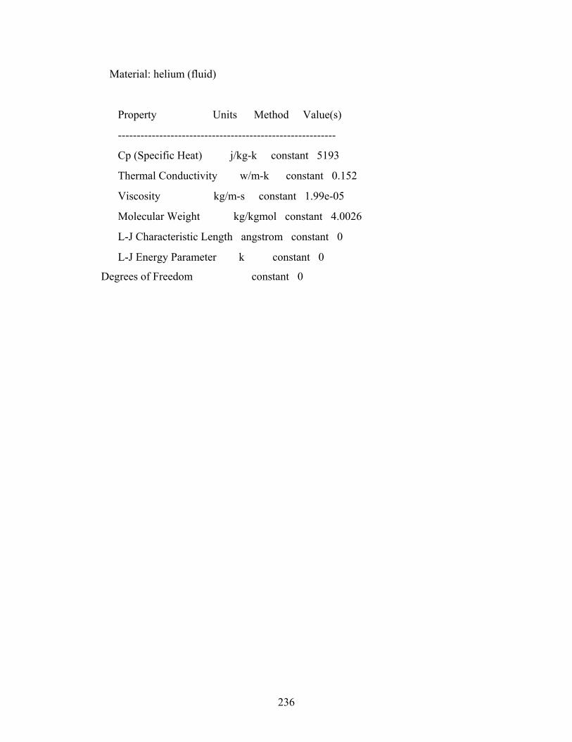
236
Material: helium (fluid)
Property Units Method Value(s)
----------------------------------------------------------
Cp (Specific Heat) j/kg-k constant 5193
Thermal Conductivity w/m-k constant 0.152
Viscosity kg/m-s constant 1.99e-05
Molecular Weight kg/kgmol constant 4.0026
L-J Characteristic Length angstrom constant 0
L-J Energy Parameter k constant 0
Degrees of Freedom constant 0
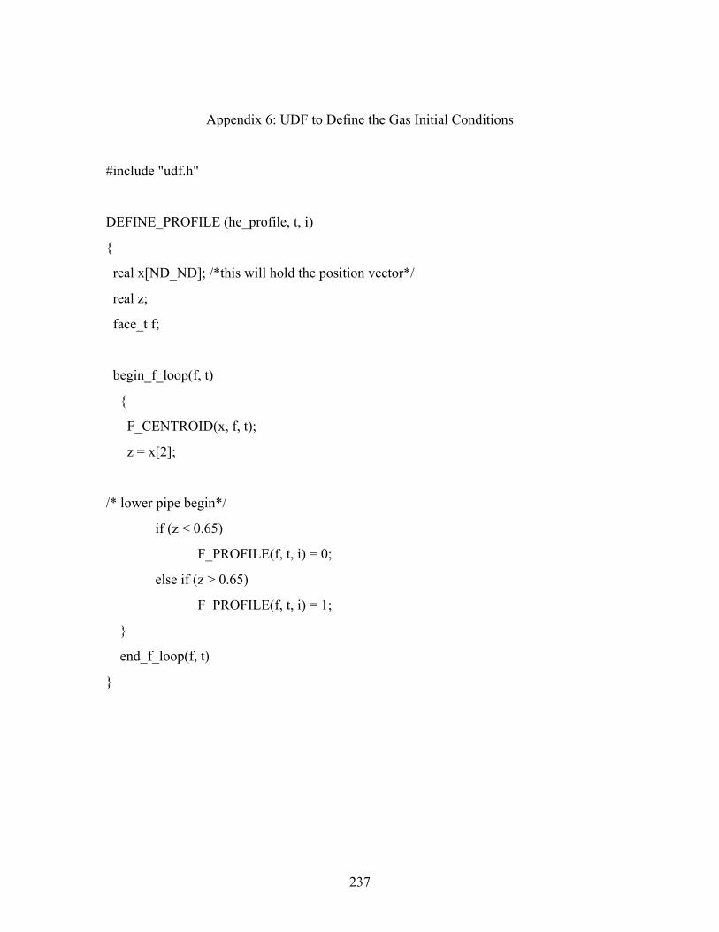
237
Appendix 6: UDF to Define the Gas Initial Conditions
#include "udf.h"
DEFINE_PROFILE (he_profile, t, i)
{
real x[ND_ND]; /*this will hold the position vector*/
real z;
face_t f;
begin_f_loop(f, t)
{
F_CENTROID(x, f, t);
z = x[2];
/* lower pipe begin*/
if (z < 0.65)
F_PROFILE(f, t, i) = 0;
else if (z > 0.65)
F_PROFILE(f, t, i) = 1;
}
end_f_loop(f, t)
}
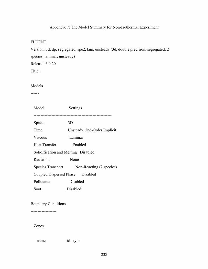
238
Appendix 7: The Model Summary for Non-Isothermal Experiment
FLUENT
Version: 3d, dp, segregated, spe2, lam, unsteady (3d, double precision, segregated, 2
species, laminar, unsteady)
Release: 6.0.20
Title:
Models
------
Model Settings
---------------------------------------------------------
Space 3D
Time Unsteady, 2nd-Order Implicit
Viscous Laminar
Heat Transfer Enabled
Solidification and Melting Disabled
Radiation None
Species Transport Non-Reacting (2 species)
Coupled Dispersed Phase Disabled
Pollutants Disabled
Soot Disabled
Boundary Conditions
-------------------
Zones
name id type
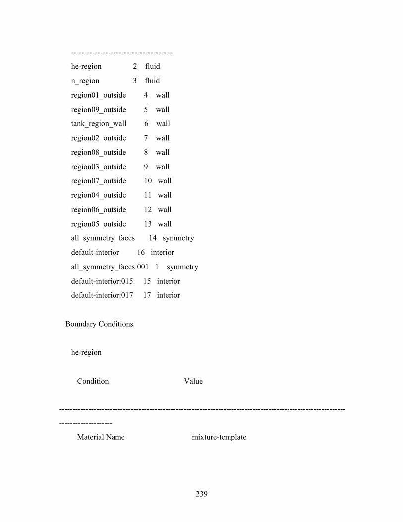
239
--------------------------------------
he-region 2 fluid
n_region 3 fluid
region01_outside 4 wall
region09_outside 5 wall
tank_region_wall 6 wall
region02_outside 7 wall
region08_outside 8 wall
region03_outside 9 wall
region07_outside 10 wall
region04_outside 11 wall
region06_outside 12 wall
region05_outside 13 wall
all_symmetry_faces 14 symmetry
default-interior 16 interior
all_symmetry_faces:001 1 symmetry
default-interior:015 15 interior
default-interior:017 17 interior
Boundary Conditions
he-region
Condition Value
------------------------------------------------------------------------------------------------------------
--------------------
Material Name mixture-template
240
Specify source terms? no
Source Terms ((mass (inactive . #f) (constant . 0) (profile ))
(x-momentum (inactive . #f) (constant . 0) (profile )) (y-momentum (inactive . #f)
(constant . 0) (profile )) (z-momentum (inactive . #f) (const
nt . 0) (profile )) (species-0 (inactive . #f) (constant . 0) (profile )) (energy (inactive . #f)
(constant . 0) (profile )))
Specify fixed values? no
Local Coordinate System for Fixed Velocities no
Fixed Values ((x-velocity (constant . 0) (profile )) (y-velocity
(constant . 0) (profile )) (z-velocity (constant . 0) (profile )) (species-0 (profile udf
he_profile) (constant . 0)) (temperature (inactive .
#f) (constant . 0) (profile )))
Motion Type 0
X-Velocity Of Zone 0
Y-Velocity Of Zone 0
Z-Velocity Of Zone 0
Rotation speed 0
241
X-Origin of Rotation-Axis 0
Y-Origin of Rotation-Axis 0
Z-Origin of Rotation-Axis 0
X-Component of Rotation-Axis 0
Y-Component of Rotation-Axis 0
Z-Component of Rotation-Axis 1
Porous zone? no
Conical porous zone? no
X-Component of Direction-1 Vector 1
Y-Component of Direction-1 Vector 1
Z-Component of Direction-1 Vector 1
X-Component of Direction-2 Vector 0
Y-Component of Direction-2 Vector 1
Z-Component of Direction-2 Vector 0
X-Coordinate of Point on Cone Axis 1
242
Y-Coordinate of Point on Cone Axis 0
Z-Coordinate of Point on Cone Axis 0
Half Angle of Cone Relative to its Axis 0
Direction-1 Viscous Resistance 0
Direction-2 Viscous Resistance 0
Direction-3 Viscous Resistance 0
Direction-1 Inertial Resistance 0
Direction-2 Inertial Resistance 0
Direction-3 Inertial Resistance 0
C0 Coefficient for Power-Law 0
C1 Coefficient for Power-Law 0
Porosity 1
Solid Material Name aluminum
n_region
Condition Value
243
------------------------------------------------------------------------------------------------------------
--------------------
Material Name mixture-template
Specify source terms? no
Source Terms ((mass (inactive . #f) (constant . 0) (profile ))
(x-momentum (inactive . #f) (constant . 0) (profile )) (y-momentum (inactive . #f)
(constant . 0) (profile )) (z-momentum (inactive . #f) (const
nt . 0) (profile )) (species-0 (inactive . #f) (constant . 0) (profile )) (energy (inactive . #f)
(constant . 0) (profile )))
Specify fixed values? yes
Local Coordinate System for Fixed Velocities no
Fixed Values ((x-velocity (inactive . #f) (constant . 0) (profile
)) (y-velocity (inactive . #f) (constant . 0) (profile )) (z-velocity (inactive . #f) (constant .
0) (profile )) (species-0 (inactive . #f) (
onstant . 0) (profile )) (temperature (constant . 291.64999) (profile )))
Motion Type 0
X-Velocity Of Zone 0
Y-Velocity Of Zone 0
Z-Velocity Of Zone 0
244
Rotation speed 0
X-Origin of Rotation-Axis 0
Y-Origin of Rotation-Axis 0
Z-Origin of Rotation-Axis 0
X-Component of Rotation-Axis 0
Y-Component of Rotation-Axis 0
Z-Component of Rotation-Axis 1
Porous zone? no
Conical porous zone? no
X-Component of Direction-1 Vector 1
Y-Component of Direction-1 Vector 1
Z-Component of Direction-1 Vector 1
X-Component of Direction-2 Vector 0
Y-Component of Direction-2 Vector 1
Z-Component of Direction-2 Vector 0
245
X-Coordinate of Point on Cone Axis 1
Y-Coordinate of Point on Cone Axis 0
Z-Coordinate of Point on Cone Axis 0
Half Angle of Cone Relative to its Axis 0
Direction-1 Viscous Resistance 0
Direction-2 Viscous Resistance 0
Direction-3 Viscous Resistance 0
Direction-1 Inertial Resistance 0
Direction-2 Inertial Resistance 0
Direction-3 Inertial Resistance 0
C0 Coefficient for Power-Law 0
C1 Coefficient for Power-Law 0
Porosity 1
Solid Material Name aluminum
region01_outside
246
Condition Value
-----------------------------------------------------------------------------------
Wall Thickness 0
Heat Generation Rate 0
Material Name aluminum
Thermal BC Type 0
Temperature 292.45001
Heat Flux 0
Convective Heat Transfer Coefficient 0
Free Stream Temperature 300
Enable shell conduction? no
Wall Motion 0
Shear Boundary Condition 0
Define wall motion relative to adjacent cell zone? yes
Apply a rotational velocity to this wall? no
Velocity Magnitude 0
X-Component of Wall Translation 1
Y-Component of Wall Translation 0
Z-Component of Wall Translation 0
Define wall velocity components? no
X-Component of Wall Translation 0
Y-Component of Wall Translation 0
Z-Component of Wall Translation 0
External Emissivity 1
External Radiation Temperature 300
(0)
(((constant . 0) (profile )))
Rotation Speed 0
X-Position of Rotation-Axis Origin 0
247
Y-Position of Rotation-Axis Origin 0
Z-Position of Rotation-Axis Origin 0
X-Component of Rotation-Axis Direction 0
Y-Component of Rotation-Axis Direction 0
Z-Component of Rotation-Axis Direction 1
X-component of shear stress 0
Y-component of shear stress 0
Z-component of shear stress 0
Surface tension gradient 0
region09_outside
Condition Value
-----------------------------------------------------------------------------------
Wall Thickness 0
Heat Generation Rate 0
Material Name aluminum
Thermal BC Type 0
Temperature 290.85001
Heat Flux 0
Convective Heat Transfer Coefficient 0
Free Stream Temperature 300
Enable shell conduction? no
Wall Motion 0
Shear Boundary Condition 0
Define wall motion relative to adjacent cell zone? yes
Apply a rotational velocity to this wall? no
Velocity Magnitude 0
X-Component of Wall Translation 1
Y-Component of Wall Translation 0
248
Z-Component of Wall Translation 0
Define wall velocity components? no
X-Component of Wall Translation 0
Y-Component of Wall Translation 0
Z-Component of Wall Translation 0
External Emissivity 1
External Radiation Temperature 300
(0)
(((constant . 0) (profile )))
Rotation Speed 0
X-Position of Rotation-Axis Origin 0
Y-Position of Rotation-Axis Origin 0
Z-Position of Rotation-Axis Origin 0
X-Component of Rotation-Axis Direction 0
Y-Component of Rotation-Axis Direction 0
Z-Component of Rotation-Axis Direction 1
X-component of shear stress 0
Y-component of shear stress 0
Z-component of shear stress 0
Surface tension gradient 0
tank_region_wall
Condition Value
-----------------------------------------------------------------------------------
Wall Thickness 0
Heat Generation Rate 0
Material Name aluminum
Thermal BC Type 0
Temperature 291.64999
249
Heat Flux 0
Convective Heat Transfer Coefficient 0
Free Stream Temperature 300
Enable shell conduction? no
Wall Motion 0
Shear Boundary Condition 0
Define wall motion relative to adjacent cell zone? yes
Apply a rotational velocity to this wall? no
Velocity Magnitude 0
X-Component of Wall Translation 1
Y-Component of Wall Translation 0
Z-Component of Wall Translation 0
Define wall velocity components? no
X-Component of Wall Translation 0
Y-Component of Wall Translation 0
Z-Component of Wall Translation 0
External Emissivity 1
External Radiation Temperature 300
(0)
(((constant . 0) (profile )))
Rotation Speed 0
X-Position of Rotation-Axis Origin 0
Y-Position of Rotation-Axis Origin 0
Z-Position of Rotation-Axis Origin 0
X-Component of Rotation-Axis Direction 0
Y-Component of Rotation-Axis Direction 0
Z-Component of Rotation-Axis Direction 1
X-component of shear stress 0
Y-component of shear stress 0
Z-component of shear stress 0
250
Surface tension gradient 0
region02_outside
Condition Value
-----------------------------------------------------------------------------------
Wall Thickness 0
Heat Generation Rate 0
Material Name aluminum
Thermal BC Type 0
Temperature 292.45001
Heat Flux 0
Convective Heat Transfer Coefficient 0
Free Stream Temperature 300
Enable shell conduction? no
Wall Motion 0
Shear Boundary Condition 0
Define wall motion relative to adjacent cell zone? yes
Apply a rotational velocity to this wall? no
Velocity Magnitude 0
X-Component of Wall Translation 1
Y-Component of Wall Translation 0
Z-Component of Wall Translation 0
Define wall velocity components? no
X-Component of Wall Translation 0
Y-Component of Wall Translation 0
Z-Component of Wall Translation 0
External Emissivity 1
External Radiation Temperature 300
(0)
251
(((constant . 0) (profile )))
Rotation Speed 0
X-Position of Rotation-Axis Origin 0
Y-Position of Rotation-Axis Origin 0
Z-Position of Rotation-Axis Origin 0
X-Component of Rotation-Axis Direction 0
Y-Component of Rotation-Axis Direction 0
Z-Component of Rotation-Axis Direction 1
X-component of shear stress 0
Y-component of shear stress 0
Z-component of shear stress 0
Surface tension gradient 0
region08_outside
Condition Value
-----------------------------------------------------------------------------------
Wall Thickness 0
Heat Generation Rate 0
Material Name aluminum
Thermal BC Type 0
Temperature 290.85001
Heat Flux 0
Convective Heat Transfer Coefficient 0
Free Stream Temperature 300
Enable shell conduction? no
Wall Motion 0
Shear Boundary Condition 0
Define wall motion relative to adjacent cell zone? yes
Apply a rotational velocity to this wall? no
252
Velocity Magnitude 0
X-Component of Wall Translation 1
Y-Component of Wall Translation 0
Z-Component of Wall Translation 0
Define wall velocity components? no
X-Component of Wall Translation 0
Y-Component of Wall Translation 0
Z-Component of Wall Translation 0
External Emissivity 1
External Radiation Temperature 300
(0)
(((constant . 0) (profile )))
Rotation Speed 0
X-Position of Rotation-Axis Origin 0
Y-Position of Rotation-Axis Origin 0
Z-Position of Rotation-Axis Origin 0
X-Component of Rotation-Axis Direction 0
Y-Component of Rotation-Axis Direction 0
Z-Component of Rotation-Axis Direction 1
X-component of shear stress 0
Y-component of shear stress 0
Z-component of shear stress 0
Surface tension gradient 0
region03_outside
Condition Value
-----------------------------------------------------------------------------------
Wall Thickness 0
Heat Generation Rate 0
253
Material Name aluminum
Thermal BC Type 0
Temperature (profile udf wall_Temp)
Heat Flux 0
Convective Heat Transfer Coefficient 0
Free Stream Temperature 300
Enable shell conduction? no
Wall Motion 0
Shear Boundary Condition 0
Define wall motion relative to adjacent cell zone? yes
Apply a rotational velocity to this wall? no
Velocity Magnitude 0
X-Component of Wall Translation 1
Y-Component of Wall Translation 0
Z-Component of Wall Translation 0
Define wall velocity components? no
X-Component of Wall Translation 0
Y-Component of Wall Translation 0
Z-Component of Wall Translation 0
External Emissivity 1
External Radiation Temperature 300
(0)
(((constant . 0) (profile )))
Rotation Speed 0
X-Position of Rotation-Axis Origin 0
Y-Position of Rotation-Axis Origin 0
Z-Position of Rotation-Axis Origin 0
X-Component of Rotation-Axis Direction 0
Y-Component of Rotation-Axis Direction 0
Z-Component of Rotation-Axis Direction 1
254
X-component of shear stress 0
Y-component of shear stress 0
Z-component of shear stress 0
Surface tension gradient 0
region07_outside
Condition Value
-----------------------------------------------------------------------------------
Wall Thickness 0
Heat Generation Rate 0
Material Name aluminum
Thermal BC Type 0
Temperature (profile udf wall_Temp)
Heat Flux 0
Convective Heat Transfer Coefficient 0
Free Stream Temperature 300
Enable shell conduction? no
Wall Motion 0
Shear Boundary Condition 0
Define wall motion relative to adjacent cell zone? yes
Apply a rotational velocity to this wall? no
Velocity Magnitude 0
X-Component of Wall Translation 1
Y-Component of Wall Translation 0
Z-Component of Wall Translation 0
Define wall velocity components? no
X-Component of Wall Translation 0
Y-Component of Wall Translation 0
Z-Component of Wall Translation 0
255
External Emissivity 1
External Radiation Temperature 300
(0)
(((constant . 0) (profile )))
Rotation Speed 0
X-Position of Rotation-Axis Origin 0
Y-Position of Rotation-Axis Origin 0
Z-Position of Rotation-Axis Origin 0
X-Component of Rotation-Axis Direction 0
Y-Component of Rotation-Axis Direction 0
Z-Component of Rotation-Axis Direction 1
X-component of shear stress 0
Y-component of shear stress 0
Z-component of shear stress 0
Surface tension gradient 0
region04_outside
Condition Value
-----------------------------------------------------------------------------------
Wall Thickness 0
Heat Generation Rate 0
Material Name aluminum
Thermal BC Type 0
Temperature (profile udf wall_Temp)
Heat Flux 0
Convective Heat Transfer Coefficient 0
Free Stream Temperature 300
Enable shell conduction? no
Wall Motion 0
256
Shear Boundary Condition 0
Define wall motion relative to adjacent cell zone? yes
Apply a rotational velocity to this wall? no
Velocity Magnitude 0
X-Component of Wall Translation 1
Y-Component of Wall Translation 0
Z-Component of Wall Translation 0
Define wall velocity components? no
X-Component of Wall Translation 0
Y-Component of Wall Translation 0
Z-Component of Wall Translation 0
External Emissivity 1
External Radiation Temperature 300
(0)
(((constant . 0) (profile )))
Rotation Speed 0
X-Position of Rotation-Axis Origin 0
Y-Position of Rotation-Axis Origin 0
Z-Position of Rotation-Axis Origin 0
X-Component of Rotation-Axis Direction 0
Y-Component of Rotation-Axis Direction 0
Z-Component of Rotation-Axis Direction 1
X-component of shear stress 0
Y-component of shear stress 0
Z-component of shear stress 0
Surface tension gradient 0
region06_outside
Condition Value
257
-----------------------------------------------------------------------------------
Wall Thickness 0
Heat Generation Rate 0
Material Name aluminum
Thermal BC Type 0
Temperature (profile udf wall_Temp)
Heat Flux 0
Convective Heat Transfer Coefficient 0
Free Stream Temperature 300
Enable shell conduction? no
Wall Motion 0
Shear Boundary Condition 0
Define wall motion relative to adjacent cell zone? yes
Apply a rotational velocity to this wall? no
Velocity Magnitude 0
X-Component of Wall Translation 1
Y-Component of Wall Translation 0
Z-Component of Wall Translation 0
Define wall velocity components? no
X-Component of Wall Translation 0
Y-Component of Wall Translation 0
Z-Component of Wall Translation 0
External Emissivity 1
External Radiation Temperature 300
(0)
(((constant . 0) (profile )))
Rotation Speed 0
X-Position of Rotation-Axis Origin 0
Y-Position of Rotation-Axis Origin 0
Z-Position of Rotation-Axis Origin 0
258
X-Component of Rotation-Axis Direction 0
Y-Component of Rotation-Axis Direction 0
Z-Component of Rotation-Axis Direction 1
X-component of shear stress 0
Y-component of shear stress 0
Z-component of shear stress 0
Surface tension gradient 0
region05_outside
Condition Value
-----------------------------------------------------------------------------------
Wall Thickness 0
Heat Generation Rate 0
Material Name aluminum
Thermal BC Type 0
Temperature (profile udf wall_Temp)
Heat Flux 0
Convective Heat Transfer Coefficient 0
Free Stream Temperature 300
Enable shell conduction? no
Wall Motion 0
Shear Boundary Condition 0
Define wall motion relative to adjacent cell zone? yes
Apply a rotational velocity to this wall? no
Velocity Magnitude 0
X-Component of Wall Translation 1
Y-Component of Wall Translation 0
Z-Component of Wall Translation 0
Define wall velocity components? no
259
X-Component of Wall Translation 0
Y-Component of Wall Translation 0
Z-Component of Wall Translation 0
External Emissivity 1
External Radiation Temperature 300
(0)
(((constant . 0) (profile )))
Rotation Speed 0
X-Position of Rotation-Axis Origin 0
Y-Position of Rotation-Axis Origin 0
Z-Position of Rotation-Axis Origin 0
X-Component of Rotation-Axis Direction 0
Y-Component of Rotation-Axis Direction 0
Z-Component of Rotation-Axis Direction 1
X-component of shear stress 0
Y-component of shear stress 0
Z-component of shear stress 0
Surface tension gradient 0
all_symmetry_faces
Condition Value
-----------------
default-interior
Condition Value
-----------------
all_symmetry_faces:001
Condition Value
-----------------
default-interior:015
Condition Value
260
-----------------
default-interior:017
Condition Value
-----------------
Solver Controls
---------------
Equations
Equation Solved
-----------------
Flow yes
he yes
Energy yes
Numerics
Numeric Enabled
---------------------------------------
Absolute Velocity Formulation yes
Unsteady Calculation Parameters
------------------------------------
Time Step (s) 0.5
Max. Iterations Per Time Step 1000
Relaxation
Variable Relaxation Factor
-------------------------------
Pressure 0.30000001
Density 0.69999999
Body Forces 0.69999999
261
Momentum 0.80000001
he 0.69999999
Energy 0.69999999
Linear Solver
Solver Termination Residual Reduction
Variable Type Criterion Tolerance
--------------------------------------------------------
Pressure V-Cycle 0.1
X-Momentum Flexible 0.1 0.7
Y-Momentum Flexible 0.1 0.7
Z-Momentum Flexible 0.1 0.7
he Flexible 0.1 0.7
Energy Flexible 0.1 0.7
Discretization Scheme
Variable Scheme
------------------------------------
Pressure PRESTO!
Pressure-Velocity Coupling PISO
Density QUICK
Momentum QUICK
he QUICK
Energy QUICK
Solution Limits
Quantity Limit

262
-----------------------------------
Minimum Absolute Pressure 1
Maximum Absolute Pressure 5000000
Minimum Temperature 1
Maximum Temperature 5000
Material Properties
-------------------
Material: helium (fluid)
Property Units Method Value(s)
---------------------------------------------------------------
Cp (Specific Heat) j/kg-k constant 5193
Thermal Conductivity w/m-k constant 0.152
Viscosity kg/m-s constant 1.9900001e-05
Molecular Weight kg/kgmol constant 4.0026002
L-J Characteristic Length angstrom constant 2.576
L-J Energy Parameter k constant 10.2
Degrees of Freedom constant 0
Material: mixture-template (mixture)
Property Units Method Value(s)
----------------------------------------------------------------------------
Mixture Species names ((he n2) ())
Density kg/m3 ideal-gas #f
Cp (Specific Heat) j/kg-k mixing-law #f
Thermal Conductivity w/m-k ideal-gas-mixing-law #f
Viscosity kg/m-s ideal-gas-mixing-law #f
263
Mass Diffusivity m2/s kinetic-theory #f
Thermal Diffusion Coefficient kg/m-s kinetic-theory #f
Thermal Expansion Coefficient 1/k constant 0
Material: nitrogen (fluid)
Property Units Method Value(s)
-----------------------------------------------------------
Cp (Specific Heat) j/kg-k constant 1040.67
Thermal Conductivity w/m-k constant 0.0242
Viscosity kg/m-s constant 1.663e-05
Molecular Weight kg/kgmol constant 28.013399
L-J Characteristic Length angstrom constant 3.6210001
L-J Energy Parameter k constant 97.529999
Degrees of Freedom constant 0
Material: oxygen (fluid)
Property Units Method Value(s)
-----------------------------------------------------------
Cp (Specific Heat) j/kg-k constant 919.31
Thermal Conductivity w/m-k constant 0.0246
Viscosity kg/m-s constant 1.919e-05
Molecular Weight kg/kgmol constant 31.9988
L-J Characteristic Length angstrom constant 3.458
L-J Energy Parameter k constant 107.4
Degrees of Freedom constant 0
Material: water-vapor (fluid)
264
Property Units Method Value(s)
----------------------------------------------------------
Cp (Specific Heat) j/kg-k constant 2014
Thermal Conductivity w/m-k constant 0.0261
Viscosity kg/m-s constant 1.34e-05
Molecular Weight kg/kgmol constant 18.01534
L-J Characteristic Length angstrom constant 2.605
L-J Energy Parameter k constant 572.4
Degrees of Freedom constant 0
Material: air (fluid)
Property Units Method Value(s)
------------------------------------------------------------
Cp (Specific Heat) j/kg-k constant 1006.43
Thermal Conductivity w/m-k constant 0.0242
Viscosity kg/m-s constant 1.7894e-05
Molecular Weight kg/kgmol constant 28.966
L-J Characteristic Length angstrom constant 3.711
L-J Energy Parameter k constant 78.6
Degrees of Freedom constant 0
Material: aluminum (solid)
Property Units Method Value(s)
---------------------------------------------------
Density kg/m3 constant 2719
Cp (Specific Heat) j/kg-k constant 871
Thermal Conductivity w/m-k constant 202.4
265
Appendix 8: UDF for Gas Initial Profile (Non-Isothermal Experiment)
#include "udf.h"
DEFINE_PROFILE (he_profile, t, i)
{
real x[ND_ND]; /*this will hold the position vector*/
real z;
face_t f;
begin_f_loop(f, t)
{
F_CENTROID(x, f, t);
z = x[2];
/* lower pipe begin*/
if (z < 0.65)
F_PROFILE(f, t, i) = 0.00000001;
else if (z > 0.65)
F_PROFILE(f, t, i) = 0.99999999;
}
end_f_loop(f, t)
}
266
Appendix 9: UDF for Wall Temperature (Non-Isothermal Experiment)
DEFINE_PROFILE (wall_Temp, t, i)
{
real x[ND_ND]; /*this will hold the position vector*/
real y; /*here y refer to x coordinate)*/
real z;
face_t f;
begin_f_loop(f, t)
{
F_CENTROID(x, f, t);
y = x[0];
z = x[2];
/* lower pipe begin*/
if (y > 0.2 && z >= 1.0 && z < 1.2)
F_PROFILE(f, t, i) = 292.45+(z-1)*(574.1-292.45)/0.2;
else if (y > 0.2 && z >= 1.2 && z < 1.7)
F_PROFILE(f, t, i) = 574.1;
else if (y > 0.2 && z >= 1.7 && z < 1.8)
F_PROFILE(f, t, i) = 574.1+(z-1.7)*(416.3-574.6)/0.1;
else if (y > 0.2 && z >= 1.8 && z < 1.97635)
F_PROFILE(f, t, i) = 416.3+(z-1.8)*(438 - 416.25)/0.17635;
else if (y >= -0.22365 && y <= 0.22365 && z > 1.923)
F_PROFILE(f, t, i) = 356 + (y + 0.22365)*(438 - 356)/0.4473;
else if (y < -0.2 && z >= 1.8 && z < 1.97635)
F_PROFILE(f, t, i) = 308.05+(z-1.8)*(356.25-308.05)/0.17635;
else if (y < -0.2 && z >= 1.0 && z < 1.8)
F_PROFILE(f, t, i) = 290.85+(z-1)*(308.05-290.85)/0.8;

267
else
F_PROFILE(f, t, i) = 290.85;
}
end_f_loop(f, t)
}
268
Appendix 10: The Model Summary for Multi-Component Experiment
FLUENT
Version: 3d, dp, segregated, spe6, lam, unsteady (3d, double precision, segregated, 6
species, laminar, unsteady)
Release: 6.0.20
Title:
Models
------
Model Settings
---------------------------------------------------------
Space 3D
Time Unsteady, 2nd-Order Implicit
Viscous Laminar
Heat Transfer Enabled
Solidification and Melting Disabled
Radiation None
Species Transport Reacting (6 species)
Coupled Dispersed Phase Disabled
Pollutants Disabled
Soot Disabled
Boundary Conditions
-------------------
Zones
name id type
269
------------------------------------
region_pipe 2 fluid
region_tank 3 fluid
wall03_up_and_cool 4 wall
wall02_graphite 5 wall
wall01_lower 6 wall
wall04_tank 7 wall
all_symm_faces 8 symmetry
default-interior 10 interior
all_symm_faces:001 1 symmetry
default-interior:009 9 interior
default-interior:011 11 interior
Boundary Conditions
region_pipe
Condition Value
----------------------------------------
Material Name mixture-template
Specify source terms? no
Source Terms ((mass (inactive . #f) (constant . 0) (profile ))
(x-momentum (inactive . #f) (constant . 0) (profile )) (y-momentum (inactive . #f)
(constant . 0) (profile )) (z-momentum (inactive . #f) (constant . 0) (profile )) (species-0
(inactive . #f) (constant . 0) (profile )) (species-1 (inactive . #f) (constant . 0) (profile ))
(species-2 (inactive . #f) (constant . 0) (profile )) (species-3 (inactive . #f) (constant . 0)
270
(profile )) (species-4 (inactive . #f) (constant . 0) (profile )) (energy (inactive . #f)
(constant . 0) (profile )))
Specify fixed values? no
Local Coordinate System for Fixed Velocities no
Fixed Values ((x-velocity (constant . 0) (profile )) (y-velocity
(constant . 0) (profile )) (z-velocity (constant . 0) (profile )) (species-0 (constant . 0)
(profile )) (species-1 (constant . 0) (profile )) (species-2 (constant . 0) (profile ))
(species-3 (constant . 0.99633998) (profile )) (species-4 (constant . 0.0036599999)
(profile )) (temperature (inactive . #f) (constant . 0) (profile )))
Motion Type 0
X-Velocity Of Zone 0
Y-Velocity Of Zone 0
Z-Velocity Of Zone 0
Rotation speed 0
X-Origin of Rotation-Axis 0
Y-Origin of Rotation-Axis 0
Z-Origin of Rotation-Axis 0
X-Component of Rotation-Axis 0
271
Y-Component of Rotation-Axis 0
Z-Component of Rotation-Axis 1
Porous zone? no
Conical porous zone? no
X-Component of Direction-1 Vector 1
Y-Component of Direction-1 Vector 1
Z-Component of Direction-1 Vector 1
X-Component of Direction-2 Vector 0
Y-Component of Direction-2 Vector 1
Z-Component of Direction-2 Vector 0
X-Coordinate of Point on Cone Axis 1
Y-Coordinate of Point on Cone Axis 0
Z-Coordinate of Point on Cone Axis 0
Half Angle of Cone Relative to its Axis 0
Direction-1 Viscous Resistance 0
272
Direction-2 Viscous Resistance 0
Direction-3 Viscous Resistance 0
Direction-1 Inertial Resistance 0
Direction-2 Inertial Resistance 0
Direction-3 Inertial Resistance 0
C0 Coefficient for Power-Law 0
C1 Coefficient for Power-Law 0
Porosity 1
Solid Material Name aluminum
region_tank
Condition Value
------------------------------------------------------------------------------------------------------------
--------------------------------
Material Name mixture-template
Specify source terms? no
273
Source Terms ((mass (inactive . #f) (constant . 0) (profile ))
(x-momentum (inactive . #f) (constant . 0) (profile )) (y-momentum (inactive . #f)
(constant . 0) (profile )) (z-momentum (inactive . #f) (constant . 0) (profile )) (species-0
(inactive . #f) (constant . 0) (profile )) (species-1 (inactive . #f) (constant . 0) (profile ))
(species-2 (inactive . #f) (constant . 0) (profile )) (species-3 (inactive . #f) (constant . 0)
(profile )) (species-4 (inactive . #f) (constant . 0) (profile )) (energy (inactive . #f)
(constant . 0) (profile )))
Specify fixed values? yes
Local Coordinate System for Fixed Velocities no
Fixed Values ((x-velocity (inactive . #f) (constant . 0) (profile
)) (y-velocity (inactive . #f) (constant . 0) (profile )) (z-velocity (inactive . #f) (constant .
0) (profile )) (species-0 (inactive . #f) (constant . 0) (profile )) (species-1 (inactive . #f)
(constant . 0) (profile )) (species-2 (inactive . #f) (constant . 0) (profile )) (species-3
(inactive . #f) (constant . 0) (profile )) (species-4 (inactive . #f) (constant . 0) (profile ))
(temperature (constant . 289.45001) (profile )))
Motion Type 0
X-Velocity Of Zone 0
Y-Velocity Of Zone 0
Z-Velocity Of Zone 0
Rotation speed 0
X-Origin of Rotation-Axis 0
Y-Origin of Rotation-Axis 0
274
Z-Origin of Rotation-Axis 0
X-Component of Rotation-Axis 0
Y-Component of Rotation-Axis 0
Z-Component of Rotation-Axis 1
Porous zone? no
Conical porous zone? no
X-Component of Direction-1 Vector 1
Y-Component of Direction-1 Vector 1
Z-Component of Direction-1 Vector 1
X-Component of Direction-2 Vector 0
Y-Component of Direction-2 Vector 1
Z-Component of Direction-2 Vector 0
X-Coordinate of Point on Cone Axis 1
Y-Coordinate of Point on Cone Axis 0
Z-Coordinate of Point on Cone Axis 0
275
Half Angle of Cone Relative to its Axis 0
Direction-1 Viscous Resistance 0
Direction-2 Viscous Resistance 0
Direction-3 Viscous Resistance 0
Direction-1 Inertial Resistance 0
Direction-2 Inertial Resistance 0
Direction-3 Inertial Resistance 0
C0 Coefficient for Power-Law 0
C1 Coefficient for Power-Law 0
Porosity 1
Solid Material Name aluminum
wall03_up_and_cool
Condition Value
-----------------------------------------------------------------------------------------------------
--------------------------------
276
Wall Thickness 0
Heat Generation Rate 0
Material Name aluminum
Thermal BC Type 0
Temperature (profile udf wall_Temp)
Heat Flux 0
Convective Heat Transfer Coefficient 0
Free Stream Temperature 300
Enable shell conduction? no
Wall Motion 0
Shear Boundary Condition 0
Define wall motion relative to adjacent cell zone? yes
Apply a rotational velocity to this wall? no
Velocity Magnitude 0
X-Component of Wall Translation 1
277
Y-Component of Wall Translation 0
Z-Component of Wall Translation 0
Define wall velocity components? no
X-Component of Wall Translation 0
Y-Component of Wall Translation 0
Z-Component of Wall Translation 0
External Emissivity 1
External Radiation Temperature 300
Activate surface reactions? no
(0 0 0 0 0)
(((constant . 0) (profile )) ((constant . 0) (profile
)) ((constant . 0) (profile )) ((constant . 0) (profile )) ((constant . 0) (profile )))
Rotation Speed 0
X-Position of Rotation-Axis Origin 0
Y-Position of Rotation-Axis Origin 0
Z-Position of Rotation-Axis Origin 0
278
X-Component of Rotation-Axis Direction 0
Y-Component of Rotation-Axis Direction 0
Z-Component of Rotation-Axis Direction 1
X-component of shear stress 0
Y-component of shear stress 0
Z-component of shear stress 0
Surface tension gradient 0
wall02_graphite
Condition Value
-----------------------------------------------------------------------------------------------------
--------------------------------------------------------------------------------------------------
Wall Thickness 0
Heat Generation Rate 0
Material Name aluminum
Thermal BC Type 0
279
Temperature (profile udf wall_Temp)
Heat Flux 0
Convective Heat Transfer Coefficient 0
Free Stream Temperature 300
Enable shell conduction? no
Wall Motion 0
Shear Boundary Condition 0
Define wall motion relative to adjacent cell zone? yes
Apply a rotational velocity to this wall? no
Velocity Magnitude 0
X-Component of Wall Translation 1
Y-Component of Wall Translation 0
Z-Component of Wall Translation 0
Define wall velocity components? no
X-Component of Wall Translation 0
280
Y-Component of Wall Translation 0
Z-Component of Wall Translation 0
External Emissivity 1
External Radiation Temperature 300
Activate surface reactions? yes
(0 0 0 0 0)
(((constant . 0) (profile )) ((constant . 0) (profile
)) ((constant . 0) (profile )) ((constant . 0) (profile )) ((constant . 0) (profile )))
Rotation Speed 0
X-Position of Rotation-Axis Origin 0
Y-Position of Rotation-Axis Origin 0
Z-Position of Rotation-Axis Origin 0
X-Component of Rotation-Axis Direction 0
Y-Component of Rotation-Axis Direction 0
Z-Component of Rotation-Axis Direction 1
X-component of shear stress 0
281
Y-component of shear stress 0
Z-component of shear stress 0
Surface tension gradient 0
wall01_lower
Condition Value
-----------------------------------------------------------------------------------------------------
--------------------------------
Wall Thickness 0
Heat Generation Rate 0
Material Name aluminum
Thermal BC Type 0
Temperature (profile udf wall_Temp)
Heat Flux 0
Convective Heat Transfer Coefficient 0
Free Stream Temperature 300
282
Enable shell conduction? no
Wall Motion 0
Shear Boundary Condition 0
Define wall motion relative to adjacent cell zone? yes
Apply a rotational velocity to this wall? no
Velocity Magnitude 0
X-Component of Wall Translation 1
Y-Component of Wall Translation 0
Z-Component of Wall Translation 0
Define wall velocity components? no
X-Component of Wall Translation 0
Y-Component of Wall Translation 0
Z-Component of Wall Translation 0
External Emissivity 1
External Radiation Temperature 300
283
Activate surface reactions? no
(0 0 0 0 0)
(((constant . 0) (profile )) ((constant . 0) (profile
)) ((constant . 0) (profile )) ((constant . 0) (profile )) ((constant . 0) (profile )))
Rotation Speed 0
X-Position of Rotation-Axis Origin 0
Y-Position of Rotation-Axis Origin 0
Z-Position of Rotation-Axis Origin 0
X-Component of Rotation-Axis Direction 0
Y-Component of Rotation-Axis Direction 0
Z-Component of Rotation-Axis Direction 1
X-component of shear stress 0
Y-component of shear stress 0
Z-component of shear stress 0
Surface tension gradient 0
wall04_tank
284
Condition Value
-----------------------------------------------------------------------------------------------------
--------------------------------
Wall Thickness 0
Heat Generation Rate 0
Material Name aluminum
Thermal BC Type 0
Temperature 289.45001
Heat Flux 0
Convective Heat Transfer Coefficient 0
Free Stream Temperature 300
Enable shell conduction? no
Wall Motion 0
Shear Boundary Condition 0
Define wall motion relative to adjacent cell zone? yes
285
Apply a rotational velocity to this wall? no
Velocity Magnitude 0
X-Component of Wall Translation 1
Y-Component of Wall Translation 0
Z-Component of Wall Translation 0
Define wall velocity components? no
X-Component of Wall Translation 0
Y-Component of Wall Translation 0
Z-Component of Wall Translation 0
External Emissivity 1
External Radiation Temperature 300
Activate surface reactions? no
(0 0 0 0 0)
(((constant . 0) (profile )) ((constant . 0) (profile
)) ((constant . 0) (profile )) ((constant . 0) (profile )) ((constant . 0) (profile )))
Rotation Speed 0
286
X-Position of Rotation-Axis Origin 0
Y-Position of Rotation-Axis Origin 0
Z-Position of Rotation-Axis Origin 0
X-Component of Rotation-Axis Direction 0
Y-Component of Rotation-Axis Direction 0
Z-Component of Rotation-Axis Direction 1
X-component of shear stress 0
Y-component of shear stress 0
Z-component of shear stress 0
Surface tension gradient 0
all_symm_faces
Condition Value
-----------------
default-interior
Condition Value
-----------------
all_symm_faces:001
Condition Value
-----------------
287
default-interior:009
Condition Value
-----------------
default-interior:011
Condition Value
-----------------
Solver Controls
---------------
Equations
Equation Solved
-----------------
Flow yes
co yes
co2 yes
o2 yes
he yes
h2o yes
Energy yes
Numerics
Numeric Enabled
---------------------------------------
Absolute Velocity Formulation yes
Unsteady Calculation Parameters
------------------------------------
Time Step (s) 1
Max. Iterations Per Time Step 2000
288
Relaxation
Variable Relaxation Factor
-------------------------------
Pressure 0.30000001
Density 0.69999999
Body Forces 0.69999999
Momentum 0.1
co 0.69999999
co2 0.69999999
o2 0.69999999
he 0.69999999
h2o 0.69999999
Energy 0.69999999
Linear Solver
Solver Termination Residual Reduction
Variable Type Criterion Tolerance
--------------------------------------------------------
Pressure V-Cycle 0.1
X-Momentum Flexible 0.1 0.7
Y-Momentum Flexible 0.1 0.7
Z-Momentum Flexible 0.1 0.7
co Flexible 0.1 0.7
co2 Flexible 0.1 0.7
o2 Flexible 0.1 0.7
he Flexible 0.1 0.7
h2o Flexible 0.1 0.7
289
Energy Flexible 0.1 0.7
Discretization Scheme
Variable Scheme
-----------------------------------------------
Pressure PRESTO!
Pressure-Velocity Coupling PISO
Density QUICK
Momentum QUICK
co First Order Upwind
co2 First Order Upwind
o2 First Order Upwind
he First Order Upwind
h2o First Order Upwind
Energy QUICK
Solution Limits
Quantity Limit
-----------------------------------
Minimum Absolute Pressure 1
Maximum Absolute Pressure 5000000
Minimum Temperature 1
Maximum Temperature 5000
Material Properties
-------------------
Material: aluminum (solid)
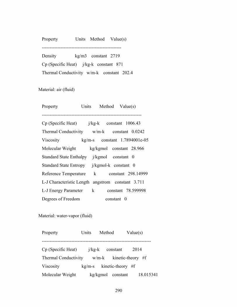
290
Property Units Method Value(s)
---------------------------------------------------
Density kg/m3 constant 2719
Cp (Specific Heat) j/kg-k constant 871
Thermal Conductivity w/m-k constant 202.4
Material: air (fluid)
Property Units Method Value(s)
----------------------------------------------------------------
Cp (Specific Heat) j/kg-k constant 1006.43
Thermal Conductivity w/m-k constant 0.0242
Viscosity kg/m-s constant 1.7894001e-05
Molecular Weight kg/kgmol constant 28.966
Standard State Enthalpy j/kgmol constant 0
Standard State Entropy j/kgmol-k constant 0
Reference Temperature k constant 298.14999
L-J Characteristic Length angstrom constant 3.711
L-J Energy Parameter k constant 78.599998
Degrees of Freedom constant 0
Material: water-vapor (fluid)
Property Units Method Value(s)
----------------------------------------------------------------------
Cp (Specific Heat) j/kg-k constant 2014
Thermal Conductivity w/m-k kinetic-theory #f
Viscosity kg/m-s kinetic-theory #f
Molecular Weight kg/kgmol constant 18.015341
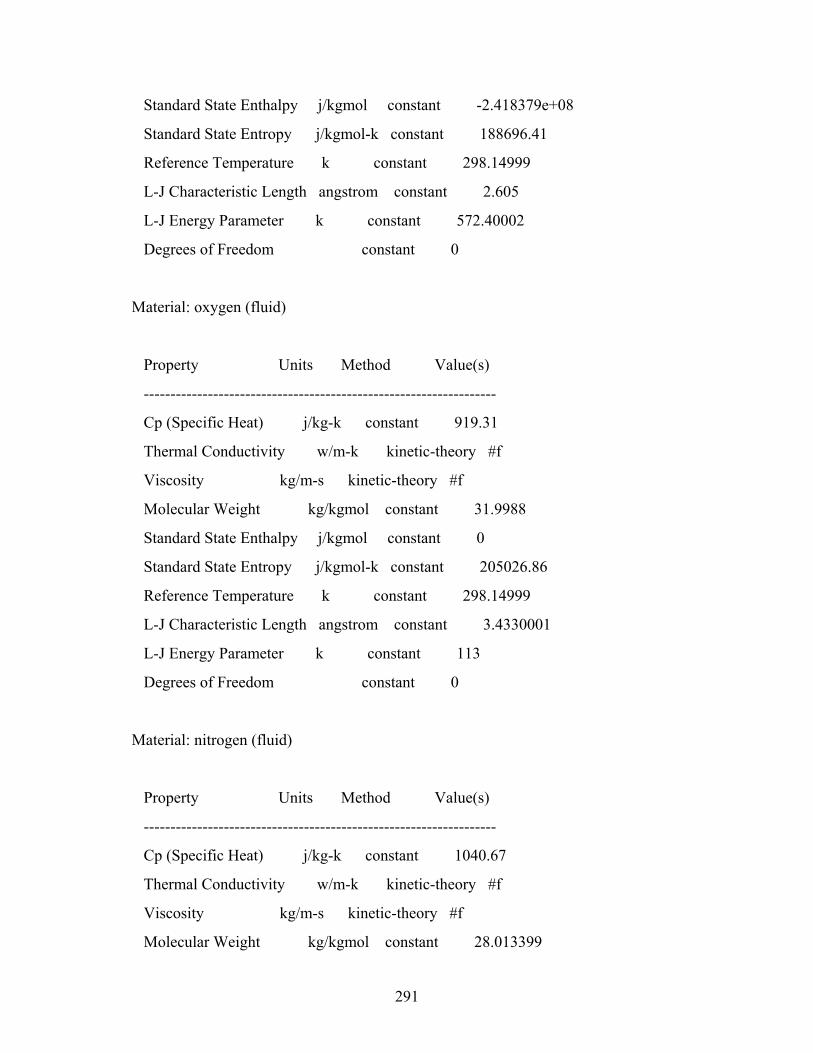
291
Standard State Enthalpy j/kgmol constant -2.418379e+08
Standard State Entropy j/kgmol-k constant 188696.41
Reference Temperature k constant 298.14999
L-J Characteristic Length angstrom constant 2.605
L-J Energy Parameter k constant 572.40002
Degrees of Freedom constant 0
Material: oxygen (fluid)
Property Units Method Value(s)
------------------------------------------------------------------
Cp (Specific Heat) j/kg-k constant 919.31
Thermal Conductivity w/m-k kinetic-theory #f
Viscosity kg/m-s kinetic-theory #f
Molecular Weight kg/kgmol constant 31.9988
Standard State Enthalpy j/kgmol constant 0
Standard State Entropy j/kgmol-k constant 205026.86
Reference Temperature k constant 298.14999
L-J Characteristic Length angstrom constant 3.4330001
L-J Energy Parameter k constant 113
Degrees of Freedom constant 0
Material: nitrogen (fluid)
Property Units Method Value(s)
------------------------------------------------------------------
Cp (Specific Heat) j/kg-k constant 1040.67
Thermal Conductivity w/m-k kinetic-theory #f
Viscosity kg/m-s kinetic-theory #f
Molecular Weight kg/kgmol constant 28.013399
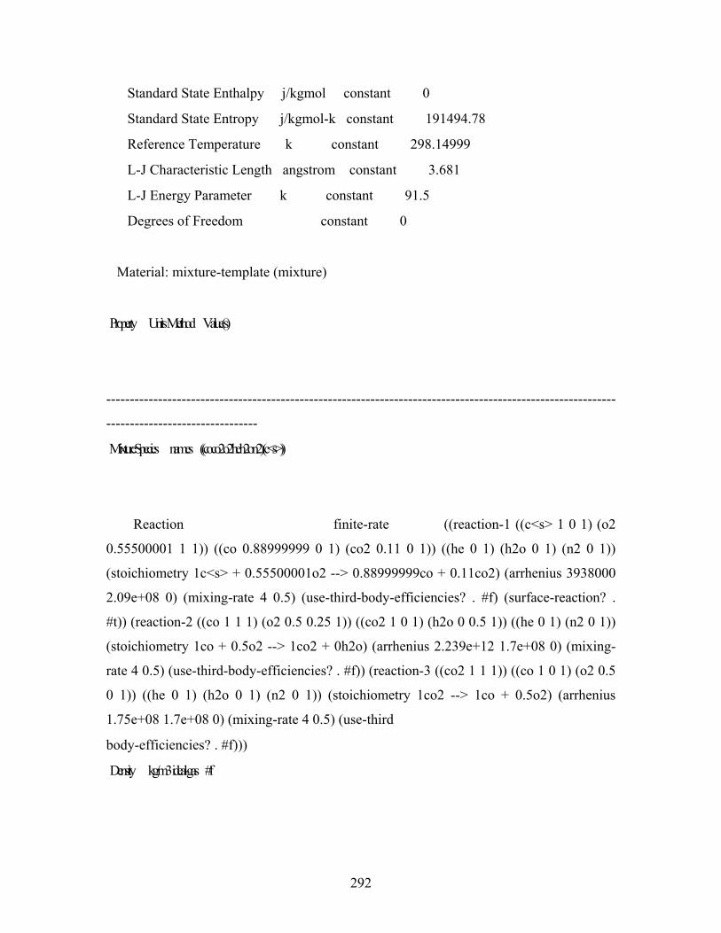
292
Standard State Enthalpy j/kgmol constant 0
Standard State Entropy j/kgmol-k constant 191494.78
Reference Temperature k constant 298.14999
L-J Characteristic Length angstrom constant 3.681
L-J Energy Parameter k constant 91.5
Degrees of Freedom constant 0
Material: mixture-template (mixture)
Property Units Method Value(s)
------------------------------------------------------------------------------------------------------------
--------------------------------
Mixture Species names ((co co2 o2 he h2o n2) (c<s>))
Reaction finite-rate ((reaction-1 ((c<s> 1 0 1) (o2
0.55500001 1 1)) ((co 0.88999999 0 1) (co2 0.11 0 1)) ((he 0 1) (h2o 0 1) (n2 0 1))
(stoichiometry 1c<s> + 0.55500001o2 --> 0.88999999co + 0.11co2) (arrhenius 3938000
2.09e+08 0) (mixing-rate 4 0.5) (use-third-body-efficiencies? . #f) (surface-reaction? .
#t)) (reaction-2 ((co 1 1 1) (o2 0.5 0.25 1)) ((co2 1 0 1) (h2o 0 0.5 1)) ((he 0 1) (n2 0 1))
(stoichiometry 1co + 0.5o2 --> 1co2 + 0h2o) (arrhenius 2.239e+12 1.7e+08 0) (mixing-
rate 4 0.5) (use-third-body-efficiencies? . #f)) (reaction-3 ((co2 1 1 1)) ((co 1 0 1) (o2 0.5
0 1)) ((he 0 1) (h2o 0 1) (n2 0 1)) (stoichiometry 1co2 --> 1co + 0.5o2) (arrhenius
1.75e+08 1.7e+08 0) (mixing-rate 4 0.5) (use-third
body-efficiencies? . #f)))
Density kg/m3 ideal-gas #f
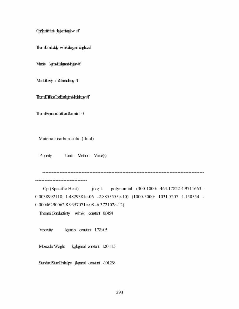
293
Cp (Specific Heat) j/kg-k mixing-law #f
Thermal Conductivity w/m-k ideal-gas-mixing-law #f
Viscosity kg/m-s ideal-gas-mixing-law #f
Mass Diffusivity m2/s kinetic-theory #f
Thermal Diffusion Coefficient kg/m-s kinetic-theory #f
Thermal Expansion Coefficient 1/k constant 0
Material: carbon-solid (fluid)
Property Units Method Value(s)
-------------------------------------------------------------------------------------------------------
---------------------------------
Cp (Specific Heat) j/kg-k polynomial (300-1000: -464.17822 4.9711663 -
0.0038992118 1.4829381e-06 -2.8855555e-10) (1000-5000: 1031.5207 1.150554 -
0.00046290062 8.9357071e-08 -6.372102e-12)
Thermal Conductivity w/m-k constant 0.0454
Viscosity kg/m-s constant 1.72e-05
Molecular Weight kg/kgmol constant 12.01115
Standard State Enthalpy j/kgmol constant -101.268
294
Standard State Entropy j/kgmol-k constant 5731.747
Reference Temperature k constant 298
L-J Characteristic Length angstrom constant 0
L-J Energy Parameter k constant 0
Degrees of Freedom constant 0
Material: carbon-monoxide (fluid)
Property Units Method Value(s)
-----------------------------------------------------------------------
Cp (Specific Heat) j/kg-k constant 1043
Thermal Conductivity w/m-k kinetic-theory #f
Viscosity kg/m-s kinetic-theory #f
Molecular Weight kg/kgmol constant 28.01055
Standard State Enthalpy j/kgmol constant -1.1053956e+08
Standard State Entropy j/kgmol-k constant 197531.64
Reference Temperature k constant 298.14999
L-J Characteristic Length angstrom constant 3.5899999
L-J Energy Parameter k constant 110
Degrees of Freedom constant 0
Material: carbon-dioxide (fluid)
Property Units Method Value(s)
-----------------------------------------------------------------------
295
Cp (Specific Heat) j/kg-k constant 840.37
Thermal Conductivity w/m-k kinetic-theory #f
Viscosity kg/m-s kinetic-theory #f
Molecular Weight kg/kgmol constant 44.009949
Standard State Enthalpy j/kgmol constant -3.9353235e+08
Standard State Entropy j/kgmol-k constant 213715.88
Reference Temperature k constant 298.14999
L-J Characteristic Length angstrom constant 3.9960001
L-J Energy Parameter k constant 190
Degrees of Freedom constant 0
Material: helium (fluid)
Property Units Method Value(s)
-------------------------------------------------------------------
Cp (Specific Heat) j/kg-k constant 5193
Thermal Conductivity w/m-k kinetic-theory #f
Viscosity kg/m-s kinetic-theory #f
Molecular Weight kg/kgmol constant 4.0026002
Standard State Enthalpy j/kgmol constant -3117.7102
Standard State Entropy j/kgmol-k constant 126029.45
Reference Temperature k constant 298.14999
L-J Characteristic Length angstrom constant 2.576
L-J Energy Parameter k constant 10.2
Degrees of Freedom constant 0
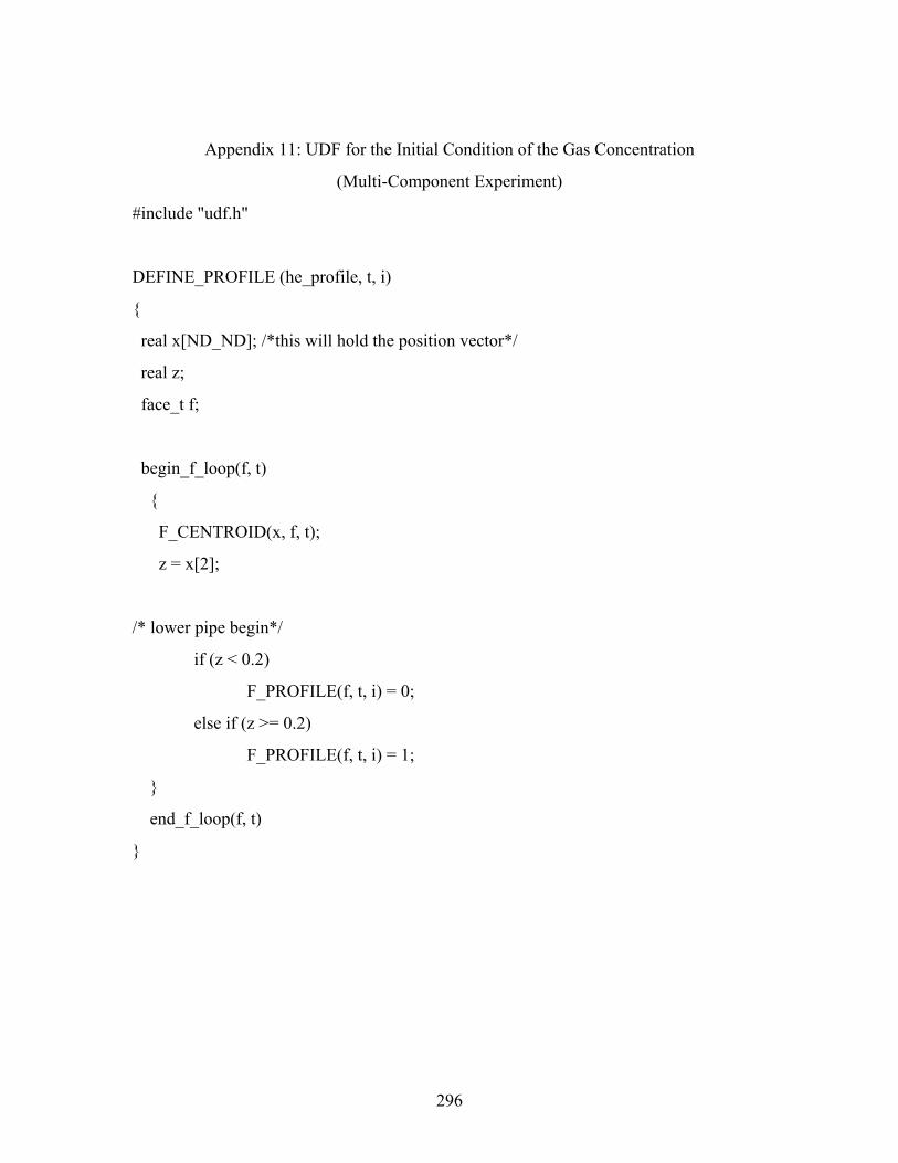
296
Appendix 11: UDF for the Initial Condition of the Gas Concentration
(Multi-Component Experiment)
#include "udf.h"
DEFINE_PROFILE (he_profile, t, i)
{
real x[ND_ND]; /*this will hold the position vector*/
real z;
face_t f;
begin_f_loop(f, t)
{
F_CENTROID(x, f, t);
z = x[2];
/* lower pipe begin*/
if (z < 0.2)
F_PROFILE(f, t, i) = 0;
else if (z >= 0.2)
F_PROFILE(f, t, i) = 1;
}
end_f_loop(f, t)
}
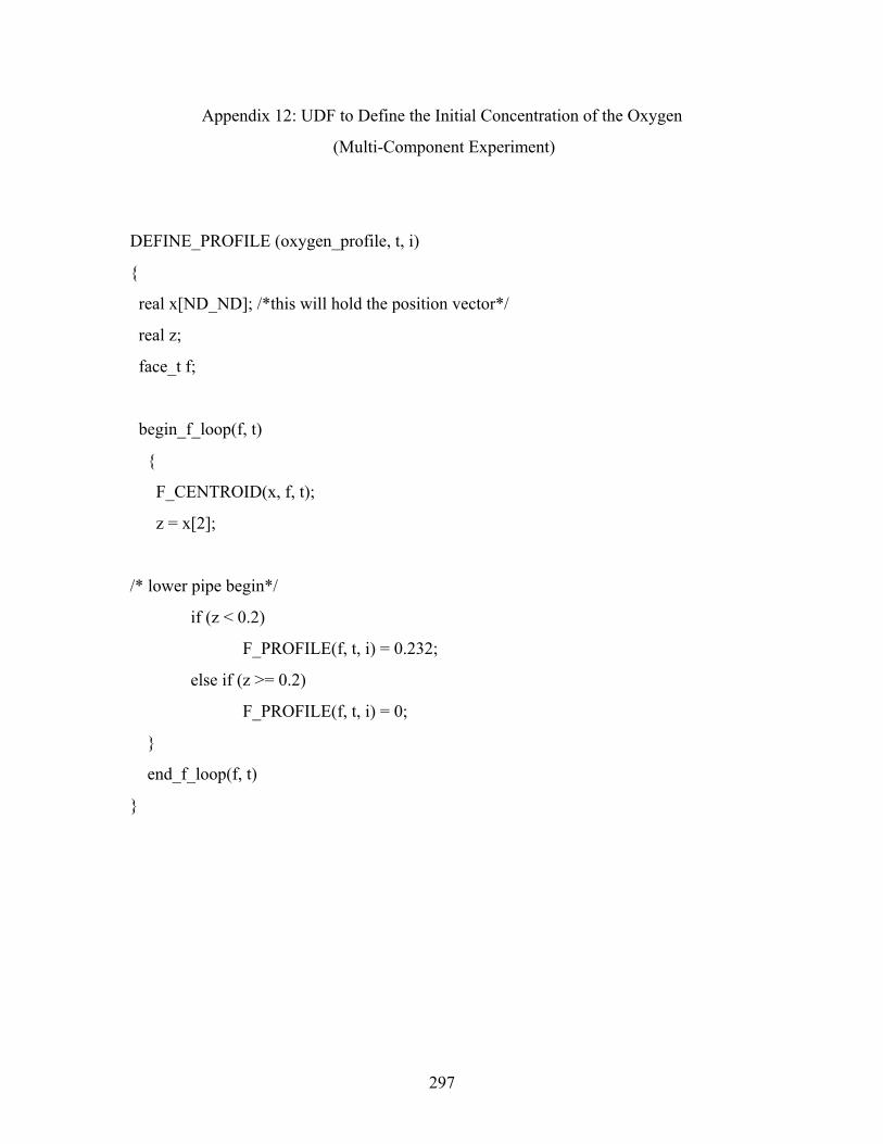
297
Appendix 12: UDF to Define the Initial Concentration of the Oxygen
(Multi-Component Experiment)
DEFINE_PROFILE (oxygen_profile, t, i)
{
real x[ND_ND]; /*this will hold the position vector*/
real z;
face_t f;
begin_f_loop(f, t)
{
F_CENTROID(x, f, t);
z = x[2];
/* lower pipe begin*/
if (z < 0.2)
F_PROFILE(f, t, i) = 0.232;
else if (z >= 0.2)
F_PROFILE(f, t, i) = 0;
}
end_f_loop(f, t)
}
298
Appendix 13: UDF for Wall Temperature Distribution (Multi-Component Experiment)
DEFINE_PROFILE (wall_Temp, t, i)
{
real x[ND_ND]; /*this will hold the position vector*/
real y; /*here y refer to x coordinate)*/
real z;
face_t f;
begin_f_loop(f, t)
{
F_CENTROID(x, f, t);
y = x[0];
z = x[2];
/* lower pipe begin*/
if (y > 0.2 && z > 0.4 && z < 0.56)
F_PROFILE(f, t, i) = 289.3 + (793 - 289.3)*(z - 0.4)/(0.56 - 0.4);
else if (y > 0.2 && z > 0.56 && z < 0.72)
F_PROFILE(f, t, i) = 793 + (938 - 793)*(z - 0.56)/(0.72 - 0.56);
else if (y > 0.2 && z > 0.72 && z < 0.78)
F_PROFILE(f, t, i) = 938 + (1018 - 938)*(z - 0.72)/(0.78 - 0.72);
else if (y > 0.2 && z > 0.78 && z < 0.87)
F_PROFILE(f, t, i) = 1018 + (1063 - 1018)*(z - 0.78)/(0.87 - 0.78);
/*graphite wall begion*/
else if (y > 0.2 && z > 0.87 && z < 0.95)
F_PROFILE(f, t, i) = 1063 + (1073 - 1063)*(z - 0.87)/(0.95 - 0.87);
299
else if (y > 0.2 && z > 0.95 && z < 1.08)
F_PROFILE(f, t, i) = 1073;
else if (y > 0.2 && z > 1.08 && z < 1.32)
F_PROFILE(f, t, i) = 1073 + (1123 - 1073)*(z - 1.08)/(1.32 - 1.08);
/*up and cool pipe begion*/
else if (y > 0.2 && z > 1.32 && z < 1.4)
F_PROFILE(f, t, i) = 1123 + (1118 - 1123)*(z - 1.32)/(1.4 - 1.32);
else if (y > 0.2 && z > 1.4 && z < 1.6)
F_PROFILE(f, t, i) = 1118 + (1003 - 1118)*(z - 1.4)/(1.6 - 1.4);
else if (y > 0.2 && z > 1.6 && z < 1.68)
F_PROFILE(f, t, i) = 1003 + (858 - 1003)*(z - 1.6)/(1.68 - 1.6);
else if (y > 0.2 && z > 1.68 && z < 1.77)
F_PROFILE(f, t, i) = 858 + (880 - 858)*(z - 1.68)/(1.77 - 1.68);
else if (y > 0.2 && z > 1.77 && z < 1.89975)
F_PROFILE(f, t, i) = 880 + (1003 - 880)*(z - 1.77)/(1.89975 - 1.77);
else if (y > 0.17 && y < 0.27025 && z > 1.89975)
F_PROFILE(f, t, i) = 1003 + (1073 - 1003)*(y - 0.27025)/(0.17 -
0.27025);
else if (y > -0.17 && y < 0.17 && z > 1.89975)
F_PROFILE(f, t, i) = 1073;
else if (y > -0.27025 && y < -0.17 && z > 1.89975)
F_PROFILE(f, t, i) = 1073 + (808 - 1073)*(y - (-0.17))/(-0.27025 - (-
0.17));
else if (y < -0.2 && z > 1.62 && z < 1.89975)
F_PROFILE(f, t, i) = 808 + (393 - 808)*(z - 1.89975)/(1.62 - 1.89975);
else if (y < -0.2 && z > 1.22 && z < 1.62)
300
F_PROFILE(f, t, i) = 393 + (289.45 - 393)*(z - 1.62)/(1.22 - 1.62);
else
F_PROFILE(f, t, i) = 289.449;
}
end_f_loop(f, t)
}
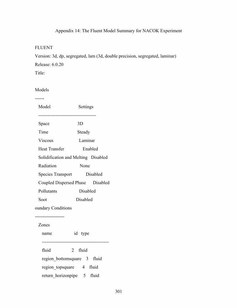
301
Appendix 14: The Fluent Model Summary for NACOK Experiment
FLUENT
Version: 3d, dp, segregated, lam (3d, double precision, segregated, laminar)
Release: 6.0.20
Title:
Models
------
Model Settings
-------------------------------------
Space 3D
Time Steady
Viscous Laminar
Heat Transfer Enabled
Solidification and Melting Disabled
Radiation None
Species Transport Disabled
Coupled Dispersed Phase Disabled
Pollutants Disabled
Soot Disabled
oundary Conditions
-------------------
Zones
name id type
-------------------------------------------
fluid 2 fluid
region_bottomsquare 3 fluid
region_topsquare 4 fluid
return_horizonpipe 5 fluid
302
region_returnpipe 6 fluid
region_pebbles 7 fluid
region_inletpipe 8 fluid
outlet 9 pressure-outlet
inlet 10 pressure-inlet
wall_returnpipe 11 wall
wall_horizonpipe 12 wall
wall_topsquare 13 wall
wall_pebblebed 14 wall
wall_bottomsquare 15 wall
wall_inletpipe 16 wall
symmetry.25 17 symmetry
default-interior 19 interior
wall_topsquare:001 1 wall
symmetry.25:018 18 symmetry
symmetry.25:020 20 symmetry
symmetry.25:021 21 symmetry
symmetry.25:022 22 symmetry
symmetry.25:023 23 symmetry
symmetry.25:024 24 symmetry
default-interior:025 25 interior
default-interior:026 26 interior
default-interior:027 27 interior
default-interior:028 28 interior
default-interior:029 29 interior
default-interior:030 30 interior
default-interior:031 31 interior
default-interior:032 32 interior
default-interior:033 33 interior
default-interior:034 34 interior
303
default-interior:035 35 interior
default-interior:036 36 interior
Boundary Conditions
fluid
Condition Value
-------------------------------------------------------------------------
Material Name air
Specify source terms? no
Source Terms ((mass (inactive . #f) (constant . 0) (profile ))
(x-momentum (inactive . #f) (constant . 0) (profile )) (y-momentum (inactive . #f)
(constant . 0) (profile )) (z-momentum (inactive . #f) (const
nt . 0) (profile )) (energy (inactive . #f) (constant . 0) (profile )))
Specify fixed values? no
Local Coordinate System for Fixed Velocities no
Fixed Values ()
Motion Type 0
X-Velocity Of Zone 0
Y-Velocity Of Zone 0
304
Z-Velocity Of Zone 0
Rotation speed 0
X-Origin of Rotation-Axis 0
Y-Origin of Rotation-Axis 0
Z-Origin of Rotation-Axis 0
X-Component of Rotation-Axis 0
Y-Component of Rotation-Axis 0
Z-Component of Rotation-Axis 1
Porous zone? no
Conical porous zone? no
X-Component of Direction-1 Vector 1
Y-Component of Direction-1 Vector 0
Z-Component of Direction-1 Vector 0
X-Component of Direction-2 Vector 0
Y-Component of Direction-2 Vector 1
305
Z-Component of Direction-2 Vector 0
X-Coordinate of Point on Cone Axis 1
Y-Coordinate of Point on Cone Axis 0
Z-Coordinate of Point on Cone Axis 0
Half Angle of Cone Relative to its Axis 0
Direction-1 Viscous Resistance 0
Direction-2 Viscous Resistance 0
Direction-3 Viscous Resistance 0
Direction-1 Inertial Resistance 0
Direction-2 Inertial Resistance 0
Direction-3 Inertial Resistance 0
C0 Coefficient for Power-Law 0
C1 Coefficient for Power-Law 0
Porosity 1
Solid Material Name aluminum
306
region_bottomsquare
Condition Value
-------------------------------------------------------------------------
Material Name air
Specify source terms? no
Source Terms ((mass (inactive . #f) (constant . 0) (profile ))
(x-momentum (inactive . #f) (constant . 0) (profile )) (y-momentum (inactive . #f)
(constant . 0) (profile )) (z-momentum (inactive . #f) (const
nt . 0) (profile )) (energy (inactive . #f) (constant . 0) (profile )))
Specify fixed values? no
Local Coordinate System for Fixed Velocities no
Fixed Values ((x-velocity (inactive . #f) (constant . 0) (profile
)) (y-velocity (inactive . #f) (constant . 0) (profile )) (z-velocity (inactive . #f) (constant .
0) (profile )) (temperature (constant . 873
(profile )))
Motion Type 0
X-Velocity Of Zone 0
Y-Velocity Of Zone 0
Z-Velocity Of Zone 0
307
Rotation speed 0
X-Origin of Rotation-Axis 0
Y-Origin of Rotation-Axis 0
Z-Origin of Rotation-Axis 0
X-Component of Rotation-Axis 0
Y-Component of Rotation-Axis 0
Z-Component of Rotation-Axis 1
Porous zone? no
Conical porous zone? no
X-Component of Direction-1 Vector 1
Y-Component of Direction-1 Vector 0
Z-Component of Direction-1 Vector 0
X-Component of Direction-2 Vector 0
Y-Component of Direction-2 Vector 1
Z-Component of Direction-2 Vector 0
308
X-Coordinate of Point on Cone Axis 1
Y-Coordinate of Point on Cone Axis 0
Z-Coordinate of Point on Cone Axis 0
Half Angle of Cone Relative to its Axis 0
Direction-1 Viscous Resistance 0
Direction-2 Viscous Resistance 0
Direction-3 Viscous Resistance 0
Direction-1 Inertial Resistance 0
Direction-2 Inertial Resistance 0
Direction-3 Inertial Resistance 0
C0 Coefficient for Power-Law 0
C1 Coefficient for Power-Law 0
Porosity 1
Solid Material Name aluminum
region_topsquare
Condition Value
309
-------------------------------------------------------------------------
Material Name air
Specify source terms? no
Source Terms ((mass (inactive . #f) (constant . 0) (profile ))
(x-momentum (inactive . #f) (constant . 0) (profile )) (y-momentum (inactive . #f)
(constant . 0) (profile )) (z-momentum (inactive . #f) (const
nt . 0) (profile )) (energy (inactive . #f) (constant . 0) (profile )))
Specify fixed values? no
Local Coordinate System for Fixed Velocities no
Fixed Values ((x-velocity (inactive . #f) (constant . 0) (profile
)) (y-velocity (inactive . #f) (constant . 0) (profile )) (z-velocity (inactive . #f) (constant .
0) (profile )) (temperature (constant . 873
(profile )))
Motion Type 0
X-Velocity Of Zone 0
Y-Velocity Of Zone 0
Z-Velocity Of Zone 0
Rotation speed 0
X-Origin of Rotation-Axis 0
310
Y-Origin of Rotation-Axis 0
Z-Origin of Rotation-Axis 0
X-Component of Rotation-Axis 0
Y-Component of Rotation-Axis 0
Z-Component of Rotation-Axis 1
Porous zone? no
Conical porous zone? no
X-Component of Direction-1 Vector 1
Y-Component of Direction-1 Vector 0
Z-Component of Direction-1 Vector 0
X-Component of Direction-2 Vector 0
Y-Component of Direction-2 Vector 1
Z-Component of Direction-2 Vector 0
X-Coordinate of Point on Cone Axis 1
Y-Coordinate of Point on Cone Axis 0
311
Z-Coordinate of Point on Cone Axis 0
Half Angle of Cone Relative to its Axis 0
Direction-1 Viscous Resistance 0
Direction-2 Viscous Resistance 0
Direction-3 Viscous Resistance 0
Direction-1 Inertial Resistance 0
Direction-2 Inertial Resistance 0
Direction-3 Inertial Resistance 0
C0 Coefficient for Power-Law 0
C1 Coefficient for Power-Law 0
Porosity 1
Solid Material Name aluminum
return_horizonpipe
Condition Value
-------------------------------------------------------------------------
Material Name air
312
Specify source terms? no
Source Terms ((mass (inactive . #f) (constant . 0) (profile ))
(x-momentum (inactive . #f) (constant . 0) (profile )) (y-momentum (inactive . #f)
(constant . 0) (profile )) (z-momentum (inactive . #f) (const
nt . 0) (profile )) (energy (inactive . #f) (constant . 0) (profile )))
Specify fixed values? no
Local Coordinate System for Fixed Velocities no
Fixed Values ((x-velocity (inactive . #f) (constant . 0) (profile
)) (y-velocity (inactive . #f) (constant . 0) (profile )) (z-velocity (inactive . #f) (constant .
0) (profile )) (temperature (constant . 473
(profile )))
Motion Type 0
X-Velocity Of Zone 0
Y-Velocity Of Zone 0
Z-Velocity Of Zone 0
Rotation speed 0
X-Origin of Rotation-Axis 0
Y-Origin of Rotation-Axis 0
Z-Origin of Rotation-Axis 0
313
X-Component of Rotation-Axis 0
Y-Component of Rotation-Axis 0
Z-Component of Rotation-Axis 1
Porous zone? no
Conical porous zone? no
X-Component of Direction-1 Vector 1
Y-Component of Direction-1 Vector 0
Z-Component of Direction-1 Vector 0
X-Component of Direction-2 Vector 0
Y-Component of Direction-2 Vector 1
Z-Component of Direction-2 Vector 0
X-Coordinate of Point on Cone Axis 1
Y-Coordinate of Point on Cone Axis 0
Z-Coordinate of Point on Cone Axis 0
314
Half Angle of Cone Relative to its Axis 0
Direction-1 Viscous Resistance 0
Direction-2 Viscous Resistance 0
Direction-3 Viscous Resistance 0
Direction-1 Inertial Resistance 0
Direction-2 Inertial Resistance 0
Direction-3 Inertial Resistance 0
C0 Coefficient for Power-Law 0
C1 Coefficient for Power-Law 0
Porosity 1
Solid Material Name aluminum
region_returnpipe
Condition Value
-------------------------------------------------------------------------
Material Name air
Specify source terms? no
315
Source Terms ((mass (inactive . #f) (constant . 0) (profile ))
(x-momentum (inactive . #f) (constant . 0) (profile )) (y-momentum (inactive . #f)
(constant . 0) (profile )) (z-momentum (inactive . #f) (const
nt . 0) (profile )) (energy (inactive . #f) (constant . 0) (profile )))
Specify fixed values? no
Local Coordinate System for Fixed Velocities no
Fixed Values ((x-velocity (inactive . #f) (constant . 0) (profile
)) (y-velocity (inactive . #f) (constant . 0) (profile )) (z-velocity (inactive . #f) (constant .
0) (profile )) (temperature (constant . 473
(profile )))
Motion Type 0
X-Velocity Of Zone 0
Y-Velocity Of Zone 0
Z-Velocity Of Zone 0
Rotation speed 0
X-Origin of Rotation-Axis 0
Y-Origin of Rotation-Axis 0
Z-Origin of Rotation-Axis 0
X-Component of Rotation-Axis 0
316
Y-Component of Rotation-Axis 0
Z-Component of Rotation-Axis 1
Porous zone? no
Conical porous zone? no
X-Component of Direction-1 Vector 1
Y-Component of Direction-1 Vector 0
Z-Component of Direction-1 Vector 0
X-Component of Direction-2 Vector 0
Y-Component of Direction-2 Vector 1
Z-Component of Direction-2 Vector 0
X-Coordinate of Point on Cone Axis 1
Y-Coordinate of Point on Cone Axis 0
Z-Coordinate of Point on Cone Axis 0
Half Angle of Cone Relative to its Axis 0
Direction-1 Viscous Resistance 0

317
Direction-2 Viscous Resistance 0
Direction-3 Viscous Resistance 0
Direction-1 Inertial Resistance 0
Direction-2 Inertial Resistance 0
Direction-3 Inertial Resistance 0
C0 Coefficient for Power-Law 0
C1 Coefficient for Power-Law 0
Porosity 1
Solid Material Name aluminum
region_pebbles
Condition Value
-----------------------------------------------------------------------
Material Name air
Specify source terms? yes
Source Terms ((mass (inactive . #f) (constant . 0) (profile ))
(x-momentum (inactive . #f) (constant . 0) (profile )) (y-momentum (inactive . #f)
(constant . 0) (profile )) (z-momentum (profile udf zmom_sour
318
e) (constant . 0)) (energy (inactive . #f) (constant . 0) (profile )))
Specify fixed values? no
Local Coordinate System for Fixed Velocities no
Fixed Values ((x-velocity (inactive . #f) (constant . 0) (profile
)) (y-velocity (inactive . #f) (constant . 0) (profile )) (z-velocity (inactive . #f) (constant .
0) (profile )) (temperature (constant . 873
(profile )))
Motion Type 0
X-Velocity Of Zone 0
Y-Velocity Of Zone 0
Z-Velocity Of Zone 0
Rotation speed 0
X-Origin of Rotation-Axis 0
Y-Origin of Rotation-Axis 0
Z-Origin of Rotation-Axis 0
X-Component of Rotation-Axis 0
Y-Component of Rotation-Axis 0
319
Z-Component of Rotation-Axis 1
Porous zone? yes
Conical porous zone? no
X-Component of Direction-1 Vector 1
Y-Component of Direction-1 Vector 0
Z-Component of Direction-1 Vector 0
X-Component of Direction-2 Vector 0
Y-Component of Direction-2 Vector 1
Z-Component of Direction-2 Vector 0
X-Coordinate of Point on Cone Axis 1
Y-Coordinate of Point on Cone Axis 0
Z-Coordinate of Point on Cone Axis 0
Half Angle of Cone Relative to its Axis 0
Direction-1 Viscous Resistance 0
Direction-2 Viscous Resistance 0
320
Direction-3 Viscous Resistance 0
Direction-1 Inertial Resistance 0
Direction-2 Inertial Resistance 0
Direction-3 Inertial Resistance 0
C0 Coefficient for Power-Law 0
C1 Coefficient for Power-Law 0
Porosity 0.39500001
Solid Material Name aluminum
region_inletpipe
Condition Value
-------------------------------------------------------------------------
Material Name air
Specify source terms? no
Source Terms ((mass (inactive . #f) (constant . 0) (profile ))
(x-momentum (inactive . #f) (constant . 0) (profile )) (y-momentum (inactive . #f)
(constant . 0) (profile )) (z-momentum (inactive . #f) (const
nt . 0) (profile )) (energy (inactive . #f) (constant . 0) (profile )))
Specify fixed values? no
321
Local Coordinate System for Fixed Velocities no
Fixed Values ((x-velocity (inactive . #f) (constant . 0) (profile
)) (y-velocity (inactive . #f) (constant . 0) (profile )) (z-velocity (inactive . #f) (constant .
0) (profile )) (temperature (constant . 473
(profile )))
Motion Type 0
X-Velocity Of Zone 0
Y-Velocity Of Zone 0
Z-Velocity Of Zone 0
Rotation speed 0
X-Origin of Rotation-Axis 0
Y-Origin of Rotation-Axis 0
Z-Origin of Rotation-Axis 0
X-Component of Rotation-Axis 0
Y-Component of Rotation-Axis 0
Z-Component of Rotation-Axis 1
Porous zone? no
322
Conical porous zone? no
X-Component of Direction-1 Vector 1
Y-Component of Direction-1 Vector 0
Z-Component of Direction-1 Vector 0
X-Component of Direction-2 Vector 0
Y-Component of Direction-2 Vector 1
Z-Component of Direction-2 Vector 0
X-Coordinate of Point on Cone Axis 1
Y-Coordinate of Point on Cone Axis 0
Z-Coordinate of Point on Cone Axis 0
Half Angle of Cone Relative to its Axis 0
Direction-1 Viscous Resistance 0
Direction-2 Viscous Resistance 0
Direction-3 Viscous Resistance 0
Direction-1 Inertial Resistance 0
323
Direction-2 Inertial Resistance 0
Direction-3 Inertial Resistance 0
C0 Coefficient for Power-Law 0
C1 Coefficient for Power-Law 0
Porosity 1
Solid Material Name aluminum
outlet
Condition Value
------------------------------------------------
Gauge Pressure 0
Radial Equilibrium Pressure Distribution no
Backflow Total Temperature 473
is zone used in mixing-plane model? no
inlet
Condition Value
-------------------------------------------
Gauge Total Pressure 0
Supersonic/Initial Gauge Pressure 0
Total Temperature 473
Direction Specification Method 1
Coordinate System 0
X-Component of Flow Direction 1
324
Y-Component of Flow Direction 0
Z-Component of Flow Direction 0
X-Component of Axis Direction 1
Y-Component of Axis Direction 0
Z-Component of Axis Direction 0
X-Coordinate of Axis Origin 0
Y-Coordinate of Axis Origin 0
Z-Coordinate of Axis Origin 0
is zone used in mixing-plane model? no
wall_returnpipe
Condition Value
-------------------------------------------------------------
Wall Thickness 0
Heat Generation Rate 0
Material Name aluminum
Thermal BC Type 0
Temperature 473
Heat Flux 0
Convective Heat Transfer Coefficient 0
Free Stream Temperature 300
Enable shell conduction? no
Wall Motion 0
Shear Boundary Condition 0
Define wall motion relative to adjacent cell zone? yes
Apply a rotational velocity to this wall? no
Velocity Magnitude 0
X-Component of Wall Translation 1
Y-Component of Wall Translation 0
325
Z-Component of Wall Translation 0
Define wall velocity components? no
X-Component of Wall Translation 0
Y-Component of Wall Translation 0
Z-Component of Wall Translation 0
External Emissivity 1
External Radiation Temperature 300
Rotation Speed 0
X-Position of Rotation-Axis Origin 0
Y-Position of Rotation-Axis Origin 0
Z-Position of Rotation-Axis Origin 0
X-Component of Rotation-Axis Direction 0
Y-Component of Rotation-Axis Direction 0
Z-Component of Rotation-Axis Direction 1
X-component of shear stress 0
Y-component of shear stress 0
Z-component of shear stress 0
Surface tension gradient 0
wall_horizonpipe
Condition Value
-------------------------------------------------------------
Wall Thickness 0
Heat Generation Rate 0
Material Name aluminum
Thermal BC Type 0
Temperature 473
Heat Flux 0
Convective Heat Transfer Coefficient 0
326
Free Stream Temperature 300
Enable shell conduction? no
Wall Motion 0
Shear Boundary Condition 0
Define wall motion relative to adjacent cell zone? yes
Apply a rotational velocity to this wall? no
Velocity Magnitude 0
X-Component of Wall Translation 1
Y-Component of Wall Translation 0
Z-Component of Wall Translation 0
Define wall velocity components? no
X-Component of Wall Translation 0
Y-Component of Wall Translation 0
Z-Component of Wall Translation 0
External Emissivity 1
External Radiation Temperature 300
Rotation Speed 0
X-Position of Rotation-Axis Origin 0
Y-Position of Rotation-Axis Origin 0
Z-Position of Rotation-Axis Origin 0
X-Component of Rotation-Axis Direction 0
Y-Component of Rotation-Axis Direction 0
Z-Component of Rotation-Axis Direction 1
X-component of shear stress 0
Y-component of shear stress 0
Z-component of shear stress 0
Surface tension gradient 0
wall_topsquare
327
Condition Value
-------------------------------------------------------------
Wall Thickness 0
Heat Generation Rate 0
Material Name aluminum
Thermal BC Type 0
Temperature 1273
Heat Flux 0
Convective Heat Transfer Coefficient 0
Free Stream Temperature 300
Enable shell conduction? no
Wall Motion 0
Shear Boundary Condition 0
Define wall motion relative to adjacent cell zone? yes
Apply a rotational velocity to this wall? no
Velocity Magnitude 0
X-Component of Wall Translation 1
Y-Component of Wall Translation 0
Z-Component of Wall Translation 0
Define wall velocity components? no
X-Component of Wall Translation 0
Y-Component of Wall Translation 0
Z-Component of Wall Translation 0
External Emissivity 1
External Radiation Temperature 300
Rotation Speed 0
X-Position of Rotation-Axis Origin 0
Y-Position of Rotation-Axis Origin 0
Z-Position of Rotation-Axis Origin 0
X-Component of Rotation-Axis Direction 0
328
Y-Component of Rotation-Axis Direction 0
Z-Component of Rotation-Axis Direction 1
X-component of shear stress 0
Y-component of shear stress 0
Z-component of shear stress 0
Surface tension gradient 0
wall_pebblebed
Condition Value
-------------------------------------------------------------
Wall Thickness 0
Heat Generation Rate 0
Material Name aluminum
Thermal BC Type 0
Temperature 1273
Heat Flux 0
Convective Heat Transfer Coefficient 0
Free Stream Temperature 300
Enable shell conduction? no
Wall Motion 0
Shear Boundary Condition 0
Define wall motion relative to adjacent cell zone? yes
Apply a rotational velocity to this wall? no
Velocity Magnitude 0
X-Component of Wall Translation 1
Y-Component of Wall Translation 0
Z-Component of Wall Translation 0
Define wall velocity components? no
X-Component of Wall Translation 0
329
Y-Component of Wall Translation 0
Z-Component of Wall Translation 0
External Emissivity 1
External Radiation Temperature 300
Rotation Speed 0
X-Position of Rotation-Axis Origin 0
Y-Position of Rotation-Axis Origin 0
Z-Position of Rotation-Axis Origin 0
X-Component of Rotation-Axis Direction 0
Y-Component of Rotation-Axis Direction 0
Z-Component of Rotation-Axis Direction 1
X-component of shear stress 0
Y-component of shear stress 0
Z-component of shear stress 0
Surface tension gradient 0
wall_bottomsquare
Condition Value
-------------------------------------------------------------
Wall Thickness 0
Heat Generation Rate 0
Material Name aluminum
Thermal BC Type 0
Temperature 1273
Heat Flux 0
Convective Heat Transfer Coefficient 0
Free Stream Temperature 300
Enable shell conduction? no
Wall Motion 0
330
Shear Boundary Condition 0
Define wall motion relative to adjacent cell zone? yes
Apply a rotational velocity to this wall? no
Velocity Magnitude 0
X-Component of Wall Translation 1
Y-Component of Wall Translation 0
Z-Component of Wall Translation 0
Define wall velocity components? no
X-Component of Wall Translation 0
Y-Component of Wall Translation 0
Z-Component of Wall Translation 0
External Emissivity 1
External Radiation Temperature 300
Rotation Speed 0
X-Position of Rotation-Axis Origin 0
Y-Position of Rotation-Axis Origin 0
Z-Position of Rotation-Axis Origin 0
X-Component of Rotation-Axis Direction 0
Y-Component of Rotation-Axis Direction 0
Z-Component of Rotation-Axis Direction 1
X-component of shear stress 0
Y-component of shear stress 0
Z-component of shear stress 0
Surface tension gradient 0
wall_inletpipe
Condition Value
-------------------------------------------------------------
Wall Thickness 0
331
Heat Generation Rate 0
Material Name aluminum
Thermal BC Type 0
Temperature 473
Heat Flux 0
Convective Heat Transfer Coefficient 0
Free Stream Temperature 300
Enable shell conduction? no
Wall Motion 0
Shear Boundary Condition 0
Define wall motion relative to adjacent cell zone? yes
Apply a rotational velocity to this wall? no
Velocity Magnitude 0
X-Component of Wall Translation 1
Y-Component of Wall Translation 0
Z-Component of Wall Translation 0
Define wall velocity components? no
X-Component of Wall Translation 0
Y-Component of Wall Translation 0
Z-Component of Wall Translation 0
External Emissivity 1
External Radiation Temperature 300
Rotation Speed 0
X-Position of Rotation-Axis Origin 0
Y-Position of Rotation-Axis Origin 0
Z-Position of Rotation-Axis Origin 0
X-Component of Rotation-Axis Direction 0
Y-Component of Rotation-Axis Direction 0
Z-Component of Rotation-Axis Direction 1
X-component of shear stress 0
332
Y-component of shear stress 0
Z-component of shear stress 0
Surface tension gradient 0
symmetry.25
Condition Value
-----------------
default-interior
Condition Value
-----------------
wall_topsquare:001
Condition Value
-------------------------------------------------------------
Wall Thickness 0
Heat Generation Rate 0
Material Name aluminum
Thermal BC Type 0
Temperature 1273
Heat Flux 0
Convective Heat Transfer Coefficient 0
Free Stream Temperature 300
Enable shell conduction? no
Wall Motion 0
Shear Boundary Condition 0
Define wall motion relative to adjacent cell zone? yes
333
Apply a rotational velocity to this wall? no
Velocity Magnitude 0
X-Component of Wall Translation 1
Y-Component of Wall Translation 0
Z-Component of Wall Translation 0
Define wall velocity components? no
X-Component of Wall Translation 0
Y-Component of Wall Translation 0
Z-Component of Wall Translation 0
External Emissivity 1
External Radiation Temperature 300
Rotation Speed 0
X-Position of Rotation-Axis Origin 0
Y-Position of Rotation-Axis Origin 0
Z-Position of Rotation-Axis Origin 0
X-Component of Rotation-Axis Direction 0
Y-Component of Rotation-Axis Direction 0
Z-Component of Rotation-Axis Direction 1
X-component of shear stress 0
Y-component of shear stress 0
Z-component of shear stress 0
Surface tension gradient 0
symmetry.25:018
Condition Value
-----------------
symmetry.25:020
Condition Value
-----------------
334
symmetry.25:021
Condition Value
-----------------
symmetry.25:022
Condition Value
-----------------
symmetry.25:023
Condition Value
-----------------
symmetry.25:024
Condition Value
-----------------
default-interior:025
Condition Value
-----------------
default-interior:026
Condition Value
-----------------
default-interior:027
Condition Value
-----------------
default-interior:028
Condition Value
-----------------
default-interior:029
Condition Value
-----------------
default-interior:030
335
Condition Value
-----------------
default-interior:031
Condition Value
-----------------
default-interior:032
Condition Value
-----------------
default-interior:033
Condition Value
-----------------
default-interior:034
Condition Value
-----------------
default-interior:035
Condition Value
-----------------
default-interior:036
336
Condition Value
-----------------
olver Controls
---------------
Equations
Equation Solved
-----------------
Flow yes
Energy yes
Numerics
Numeric Enabled
---------------------------------------
Absolute Velocity Formulation yes
Relaxation
Variable Relaxation Factor
-------------------------------
Pressure 0.2
Density 0.30000001
Body Forces 0.30000001
Momentum 0.050000001
Energy 0.2
Linear Solver
337
Solver Termination Residual Reduction
Variable Type Criterion Tolerance
--------------------------------------------------------
Pressure V-Cycle 0.1
X-Momentum Flexible 0.1 0.7
Y-Momentum Flexible 0.1 0.7
Z-Momentum Flexible 0.1 0.7
Energy Flexible 0.1 0.7
Discretization Scheme
Variable Scheme
------------------------------------------------
Pressure PRESTO!
Pressure-Velocity Coupling PISO
Momentum Second Order Upwind
Energy Second Order Upwind
Solution Limits
Quantity Limit
-----------------------------------
Minimum Absolute Pressure 1
Maximum Absolute Pressure 5000000
Minimum Temperature 1
Maximum Temperature 5000
FLUENT
Version: 3d, dp, segregated, lam (3d, double precision, segregated, laminar)
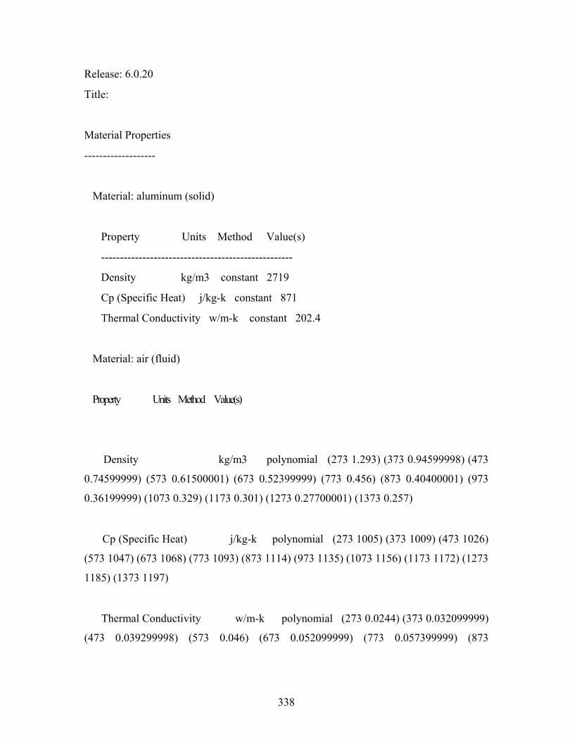
338
Release: 6.0.20
Title:
Material Properties
-------------------
Material: aluminum (solid)
Property Units Method Value(s)
---------------------------------------------------
Density kg/m3 constant 2719
Cp (Specific Heat) j/kg-k constant 871
Thermal Conductivity w/m-k constant 202.4
Material: air (fluid)
Property Units Method Value(s)
Density kg/m3 polynomial (273 1.293) (373 0.94599998) (473
0.74599999) (573 0.61500001) (673 0.52399999) (773 0.456) (873 0.40400001) (973
0.36199999) (1073 0.329) (1173 0.301) (1273 0.27700001) (1373 0.257)
Cp (Specific Heat) j/kg-k polynomial (273 1005) (373 1009) (473 1026)
(573 1047) (673 1068) (773 1093) (873 1114) (973 1135) (1073 1156) (1173 1172) (1273
1185) (1373 1197)
Thermal Conductivity w/m-k polynomial (273 0.0244) (373 0.032099999)
(473 0.039299998) (573 0.046) (673 0.052099999) (773 0.057399999) (873
339
0.062199999) (973 0.067100003) (1073 0.071800001) (1173 0.076300003) (1273
0.080700003) (
373 0.085000001)
Viscosity kg/m-s polynomial (273 1.72e-05) (373 2.1899999e-05)
(473 2.6e-05) (573 2.9700001e-05) (673 3.3e-05) (773 3.6199999e-05) (873 3.9099999e-
05) (973 4.1800002e-05) (1073 4.4299999e-05) (1173 4.6699999e-05) (1273
.8999998e-05) (1373 5.1200001e-05)
Molecular Weight kg/kgmol constant 28.966
L-J Characteristic Length angstrom constant 3.711
L-J Energy Parameter k constant 78.599998
Thermal Expansion Coefficient 1/k constant 0.0035000001
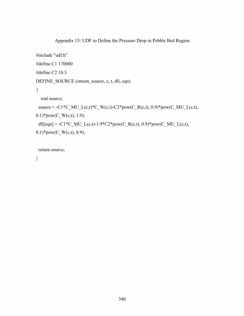
340
Appendix 15: UDF to Define the Pressure Drop in Pebble Bed Region
#include "udf.h"
#define C1 170000
#define C2 10.3
DEFINE_SOURCE (zmom_source, c, t, dS, eqn)
{
real source;
source = -C1*C_MU_L(c,t)*C_W(c,t)-C2*pow(C_R(c,t), 0.9)*pow(C_MU_L(c,t),
0.1)*pow(C_W(c,t), 1.9);
dS[eqn] = -C1*C_MU_L(c,t)-1.9*C2*pow(C_R(c,t), 0.9)*pow(C_MU_L(c,t),
0.1)*pow(C_W(c,t), 0.9);
return source;
}


![Loca Phenomena [Autosaved]](https://img.pdfslide.us/doc/110x75/55cf96c8550346d0338dc1cd/loca-phenomena-autosaved.jpg)