Embed Size (px)
Citation preview
Page 1 of 40 Form 18 Evaluation of LNG Facility Siting, Design, Construction, and Equipment (Rev. 03/18/11 49 CFR 193 through Amendment 193-23 effective 1 January 2011)
LNG Construction Inspection – Inspection Modules
Introduction & Instructions
The construction of an LNG facility usually takes approximately two years. The PHMSA Form 18 Evaluation
of LNG Facility Siting, design, Construction, and Equipment (Rev. 3/18/09) (―Form 18‖) consists of 40
pages addressing the construction requirements of 49 CFR Part 193. The purpose of this document is to break
the Form 18 into inspection modules that can be individually accomplished more or less bimonthly so that all of
the elements of the Form 18 can be addressed prior to operation of new LNG facilities. Note that not all
modules will apply to all LNG facilities, more than one module may be completed per site visit, and an
individual module may take more than one site visit to complete. The modules are solely for the convenience of
the Inspector and the Operator. All of the usual inspection procedures apply and the entire Form 18 must be
completed before the inspection is complete and the documentation added to the permanent Operator File..
Use of the Form 18 Post Inspection Memorandum (PIM) is NOT recommended. An Activity ID should be
established for each new LNG facility. Information regarding each site visit should be recorded as a separate
assignment under the same Activity ID number. At the conclusion of the inspection, the Activity Report should
be used as the Post Inspection Memorandum. Be sure to consider this as the Assignment Activity report is
prepared for each site visit. Above all, keep up with the Assignment Activity entries and the entries into the
overall Form 18 as each site visit is completed.
A completed Form 18 should be submitted to the Regional Director within 60 days of completion of the
inspection. The Assignment Activity Report (serving as the PIM) should be completed and submitted to the
Regional Director within 30 days of completion of the inspection (completion of all Modules) and must be filed
with the final copy of the Form 18.
Modules (hyperlinked)
1. Preliminaries – Cover Sheet, Subpart A – Reporting & Subpart B – Siting Requirements (pp. 2-6)
2. Subpart C – Design; Subpart D- Construction; NFPA 59A Emergency Shutdown (pp. 7-10)
3. Protective Enclosures, Security, Power Sources (pp. 11-12)
4. Plant Siting & Layout, Soil Protection, Process Equipment & Vaporization Facilities, General & Basic
Design (pp. 13-17)
5. Seismic Design, Container Insulation, Foundations, API 620 Tanks & Field-Fabricated Containers
(193.2101 (pp. 18-20)
6. High Pressure Tanks (>15 psi) (p. 21-22)
7. Concrete Tanks, Relief Devices, Piping Systems & Components, Welded Pipe Tests & Inspection (pp.
23-26)
8. Corrosion Control (NFPA 59A & 193.2304) (p. 27)
9. LNG Level Gauging, Refrigerant & Process Fluids, Pressure & Vacuum Gauges, Temperature
Monitoring (p. 28)
10. Electrical Equipment, Grounding & Bonding (p. 29-30)
11. Transfer of LNG & Refrigerants (pp. 31-32)
12. Fire Protection Provisions (pp. 33-34)
13. ASME Small Containers (max 100,000 gal/tank and 280,000 gal aggregate) (pp. 35-38)
14. Construction Acceptance (193.2303); Design & Fabrication (193.2703); Construction, Installation,
Inspection and Testing (193.2705); Records (193.2119); Warning Signs (193.2917) (pp. 39-40)
Page 2 of 40 Form 18 Evaluation of LNG Facility Siting, Design, Construction, and Equipment (Rev. 03/18/11 49 CFR 193 through Amendment 193-23 effective 1 January 2011)
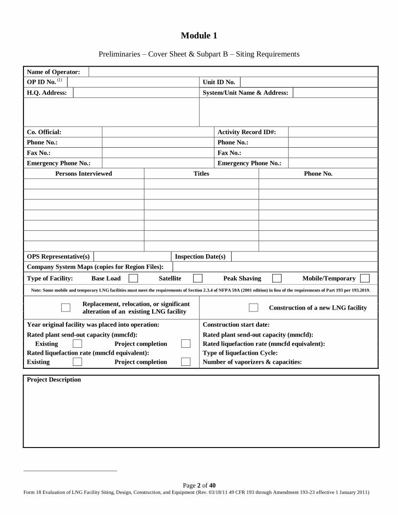
Module 1
Preliminaries – Cover Sheet & Subpart B – Siting Requirements
Name of Operator:
OP ID No. (1)
Unit ID No.
H.Q. Address: System/Unit Name & Address:
Co. Official: Activity Record ID#:
Phone No.: Phone No.:
Fax No.: Fax No.:
Emergency Phone No.: Emergency Phone No.:
Persons Interviewed Titles Phone No.
OPS Representative(s) Inspection Date(s)
Company System Maps (copies for Region Files):
Type of Facility: Base Load Satellite Peak Shaving Mobile/Temporary
Note: Some mobile and temporary LNG facilities must meet the requirements of Section 2.3.4 of NFPA 59A (2001 edition) in lieu of the requirements of Part 193 per 193.2019.
Replacement, relocation, or significant
alteration of an existing LNG facility
Construction of a new LNG facility
Year original facility was placed into operation: Construction start date:
Rated plant send-out capacity (mmcfd): Rated plant send-out capacity (mmcfd):
Existing Project completion Rated liquefaction rate (mmcfd equivalent):
Rated liquefaction rate (mmcfd equivalent): Type of liquefaction Cycle:
Existing Project completion Number of vaporizers & capacities:
Project Description
Unless otherwise noted, all references are to 49CFR Part 193. S - Satisfactory U - Unsatisfactory N/A - Not Applicable N/C - Not Checked If an item is marked U, N/A, or N/C, an explanation must be included in this report.
Page 3 of 40 Form 18 Evaluation of LNG Facility Siting, Design, Construction, and Equipment (Rev. 03/18/11 49 CFR 193 through Amendment 193-23 effective 1 January 2011)
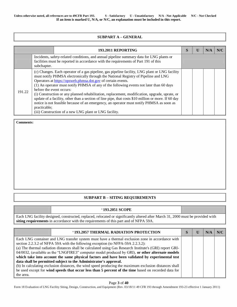
SUBPART A – GENERAL
193.2011 REPORTING S U N/A N/C
Incidents, safety-related conditions, and annual pipeline summary data for LNG plants or
facilities must be reported in accordance with the requirements of Part 191 of this
subchapter.
191.22
(c) Changes. Each operator of a gas pipeline, gas pipeline facility, LNG plant or LNG facility
must notify PHMSA electronically through the National Registry of Pipeline and LNG
Operators at https://opsweb.phmsa.dot.gov of certain events.
(1) An operator must notify PHMSA of any of the following events not later than 60 days
before the event occurs:
(i) Construction or any planned rehabilitation, replacement, modification, upgrade, uprate, or
update of a facility, other than a section of line pipe, that costs $10 million or more. If 60 day notice is not feasible because of an emergency, an operator must notify PHMSA as soon as
practicable;
(iii) Construction of a new LNG plant or LNG facility.
Comments:
SUBPART B – SITING REQUIREMENTS
'193.2051 SCOPE
Each LNG facility designed, constructed, replaced, relocated or significantly altered after March 31, 2000 must be provided with
siting requirements in accordance with the requirements of this part and of NFPA 59A.
'193.2057 THERMAL RADIATION PROTECTION S U N/A N/C
Each LNG container and LNG transfer system must have a thermal exclusion zone in accordance with
section 2.2.3.2 of NFPA 59A with the following exception (to NFPA-59A 2.2.3.2):
(a) The thermal radiation distances shall be calculated using Gas Research Institute's (GRI) report GRI-
04/0032, (available as the ―LNGFIRE3‖ computer model produced by GRI), or other alternate models
which take into account the same physical factors and have been validated by experimental test
data shall be permitted subject to the Administrator's approval. (b) In calculating exclusion distances, the wind speed producing the maximum exclusion distances shall
be used except for wind speeds that occur less than 5 percent of the time based on recorded data for
the area.
Unless otherwise noted, all references are to 49CFR Part 193. S - Satisfactory U - Unsatisfactory N/A - Not Applicable N/C - Not Checked If an item is marked U, N/A, or N/C, an explanation must be included in this report.
Page 4 of 40 Form 18 Evaluation of LNG Facility Siting, Design, Construction, and Equipment (Rev. 03/18/11 49 CFR 193 through Amendment 193-23 effective 1 January 2011)
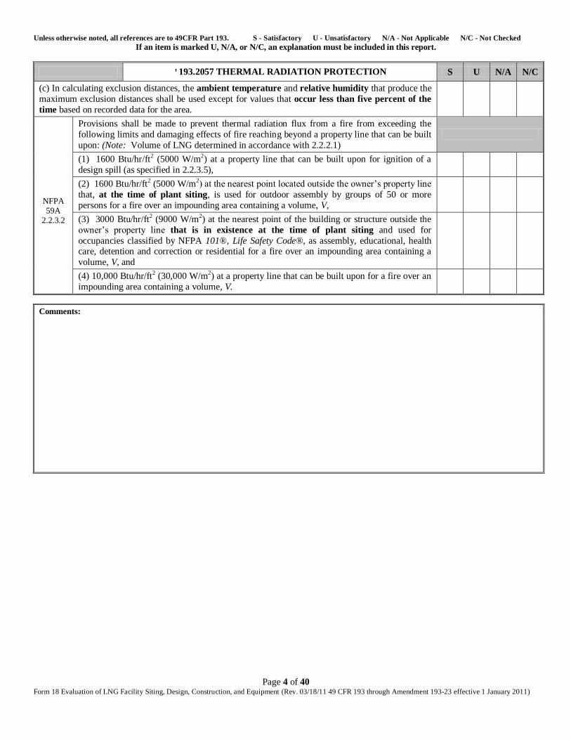
'193.2057 THERMAL RADIATION PROTECTION S U N/A N/C
(c) In calculating exclusion distances, the ambient temperature and relative humidity that produce the
maximum exclusion distances shall be used except for values that occur less than five percent of the
time based on recorded data for the area.
NFPA 59A
2.2.3.2
Provisions shall be made to prevent thermal radiation flux from a fire from exceeding the
following limits and damaging effects of fire reaching beyond a property line that can be built
upon: (Note: Volume of LNG determined in accordance with 2.2.2.1)
(1) 1600 Btu/hr/ft2 (5000 W/m2) at a property line that can be built upon for ignition of a
design spill (as specified in 2.2.3.5),
(2) 1600 Btu/hr/ft2 (5000 W/m2) at the nearest point located outside the owner’s property line
that, at the time of plant siting, is used for outdoor assembly by groups of 50 or more
persons for a fire over an impounding area containing a volume, V,
(3) 3000 Btu/hr/ft2 (9000 W/m2) at the nearest point of the building or structure outside the
owner’s property line that is in existence at the time of plant siting and used for
occupancies classified by NFPA 101®, Life Safety Code®, as assembly, educational, health care, detention and correction or residential for a fire over an impounding area containing a
volume, V, and
(4) 10,000 Btu/hr/ft2 (30,000 W/m2) at a property line that can be built upon for a fire over an
impounding area containing a volume, V.
Comments:
Unless otherwise noted, all references are to 49CFR Part 193. S - Satisfactory U - Unsatisfactory N/A - Not Applicable N/C - Not Checked If an item is marked U, N/A, or N/C, an explanation must be included in this report.
Page 5 of 40 Form 18 Evaluation of LNG Facility Siting, Design, Construction, and Equipment (Rev. 03/18/11 49 CFR 193 through Amendment 193-23 effective 1 January 2011)
'193.2059 FLAMMABLE VAPOR-GAS DISPERSION PROTECTION S U N/A N/C
Each LNG container and LNG transfer system must have a dispersion exclusion zone in accordance
with sections 2.2.3.3 and 2.2.3.4 of NFPA 59A with the following exception (to NFPA-59A 2.2.3.3 and
2.2.3.4):
(a) Flammable vapor-gas dispersion distances must be determined in accordance with the model
described in the Gas Research Institute report GRI-89/0242 and Gas Research Institute report GRI-96/0396.5, or other alternate models which take into account the same physical factors and
have been validated by experimental test data shall be permitted, subject to the Administrator's
approval (b) The following dispersion parameters must be used in computing dispersion distances:
(1) Average gas concentration in air = 2.5 percent.
(2) Dispersion conditions are a combination of those which result in longer predicted downwind
dispersion distances than other weather conditions at the site at least 90 percent of the time, based on
figures maintained by National Weather Service of the U.S. Department of Commerce, or as an
alternative where the model used gives longer distances at lower wind speeds, percent, and
atmospheric temperature = average in the region.
(3) The elevation for contour (receptor) output H = 0.5 meters.
(4) A surface roughness factor of 0.03 meters shall be used. Higher values for the roughness factor
may be used if it can be shown that the terrain both upwind and downwind of the vapor cloud has
dense vegetation and that the vapor cloud height is more than ten times the height of the obstacles
encountered by the vapor cloud.
(c) The design spill shall be determined in accordance with section 2.2.3.5.
NFPA 59A 2.2.3.3
The spacing of an LNG tank impoundment to the property line that can be built upon shall
be such that, in the event of an LNG spill specified in 2.2.3.5, an average concentration of
methane in air of 50 percent of the lower flammability limit (LFL) does not extend beyond
the property line that can be built upon, using calculations in 2.2.3.3.
NFPA 59A 2.2.3.4
Make provisions to minimize the possibility of a flammable mixture of vapors from a
design spill specified in 2.2.3.5, as appropriate, reaching a property line that can be built
upon and that would result in a distinct hazard. Flammable mixture dispersion distances
shall be determined in accordance 2.2.3.4 (a-b).
Comments:
Unless otherwise noted, all references are to 49CFR Part 193. S - Satisfactory U - Unsatisfactory N/A - Not Applicable N/C - Not Checked If an item is marked U, N/A, or N/C, an explanation must be included in this report.
Page 6 of 40 Form 18 Evaluation of LNG Facility Siting, Design, Construction, and Equipment (Rev. 03/18/11 49 CFR 193 through Amendment 193-23 effective 1 January 2011)
'193.2067 WIND FORCES S U N/A N/C
(a) LNG facilities must be designed to withstand without loss of structural or functional integrity:
(1) The direct effect of wind forces;
(2) The pressure differential between the interior and exterior of a confining, or partially confining,
structure; and
(3) In the case of impounding systems for LNG storage tanks, impact forces and potential
penetrations by wind borne missiles.
(b) The wind forces at the location of the specific facility must be based on one of the following:
(1) For shop fabricated containers of LNG or other hazardous fluids with a capacity of not more
than 70,000 gallons, use applicable wind load data in ASCE 7-05.
(2) For all other LNG facilities
(i) An assumed sustained wind velocity of not less than 150 miles per hour, unless the Administrator
finds a lower velocity is justified by adequate supportive data; or (ii) The most critical combination of wind velocity and duration, with respect to the effect on the
structure.
Comments:
Return to List
Unless otherwise noted, all references are to 49CFR Part 193. S - Satisfactory U - Unsatisfactory N/A - Not Applicable N/C - Not Checked If an item is marked U, N/A, or N/C, an explanation must be included in this report.
Page 7 of 40 Form 18 Evaluation of LNG Facility Siting, Design, Construction, and Equipment (Rev. 03/18/11 49 CFR 193 through Amendment 193-23 effective 1 January 2011)
Module 2
Subpart C – Design; Subpart D- Construction; NFPA 59A Emergency Shutdown
SUBPART C – DESIGN
SUBPART D- CONSTRUCTION
193.2155 STRUCTURAL REQUIREMENTS S U N/A N/C
(a) The structural members of an impoundment system must be designed and constructed to prevent
impairment of the system’s performance reliability and structural integrity as a result of the following:
(1) Imposed loading from—
(i) Full hydrostatic head of impounded LNG;
(ii) Hydrodynamic action from injected material;
(iii) Impingement of LNG jet trajectory discharged at any predictable angle;
(iv) Anticipated hydraulic forces from a credible opening in the component or item served, assuming the
discharge pressure equals design pressure.
(2) Erosive action from a spill, including jetting of spilling LNG, and any other anticipated erosive action
including surface water runoff, ice formation, dislodgement of ice formation, and snow removal.
(3) Effect of the temperature, any thermal gradient, and any other anticipated degradation resulting from sudden or localized contact with LNG.
(4) Fire exposure from impounded LNG or LNG from other sources.
(5) If applicable, the potential impact and loading on the dike due to –
(i) Collapse of the component or item served or adjacent components;
(ii) If the LNG facility adjoins the right-of-way of any highway or railroad, collision by or explosion of a train, tank car, or tank truck that could reasonably be expected to cause the most severe loading.
(b) An LNG storage tank must not be located within a horizontal distance of one mile (1.6 km) from the ends, or ¼ mile (0.4 km) from the nearest point of a runway, whichever is longer. The height of LNG
structures in the vicinity of an airport must comply with FAA, 14 CFR Section 1.1.
Comments:
'193.2161 DIKES S U N/A N/C
An outer wall of a component served by an impounding system may not be used as a dike unless the outer
wall is constructed of concrete.
Comments:
Unless otherwise noted, all references are to 49CFR Part 193. S - Satisfactory U - Unsatisfactory N/A - Not Applicable N/C - Not Checked If an item is marked U, N/A, or N/C, an explanation must be included in this report.
Page 8 of 40 Form 18 Evaluation of LNG Facility Siting, Design, Construction, and Equipment (Rev. 03/18/11 49 CFR 193 through Amendment 193-23 effective 1 January 2011)
193.2167 COVERED SYSTEMS S U N/A N/C
A covered impounding system is prohibited except for concrete wall designed tanks where the concrete
wall is an outer wall serving as a dike.
Comments:
193.2173 WATER REMOVAL S U N/A N/C
(a) Impoundment areas must be designed so all areas drain completely, to prevent water collection.
Drainage pumps and piping must be provided to remove water from collecting in the impoundment area.
Alternative means of draining approved by the Administrator may be acceptable.
(b) The water removal system must have adequate capacity to remove water at a rate equal to 25% of the
maximum predictable collection rate from a storm of 10-year frequency and 1-hour duration, and other
natural causes.
(c) Sump pumps for water removal must:
(1) Be operated as necessary to keep the impounding space as dry as practical; and
(2) If designed for automatic operation, must have redundant automatic shutdown controls to prevent
operation when LNG is present.
Comments:
'193.2181 IMPOUNDMENT CAPACITY: LNG STORAGE TANKS S U N/A N/C
Each impounding system serving an LNG storage tank must have a minimum volumetric liquid
impoundment capacity of:
(a) 110 percent of the LNG tank’s maximum liquid capacity for an impoundment serving a single
tank;
(b) 100 percent of all tanks or 110 percent of the largest tank’s maximum liquid capacity, whichever is
greater, for the impoundment serving more than one tank; or
(c) If the dike is designed to account for a surge in the event of catastrophic failure, then the
impoundment capacity may be reduced to 100 percent in lieu of 110 percent.
Comments:
Unless otherwise noted, all references are to 49CFR Part 193. S - Satisfactory U - Unsatisfactory N/A - Not Applicable N/C - Not Checked If an item is marked U, N/A, or N/C, an explanation must be included in this report.
Page 9 of 40 Form 18 Evaluation of LNG Facility Siting, Design, Construction, and Equipment (Rev. 03/18/11 49 CFR 193 through Amendment 193-23 effective 1 January 2011)
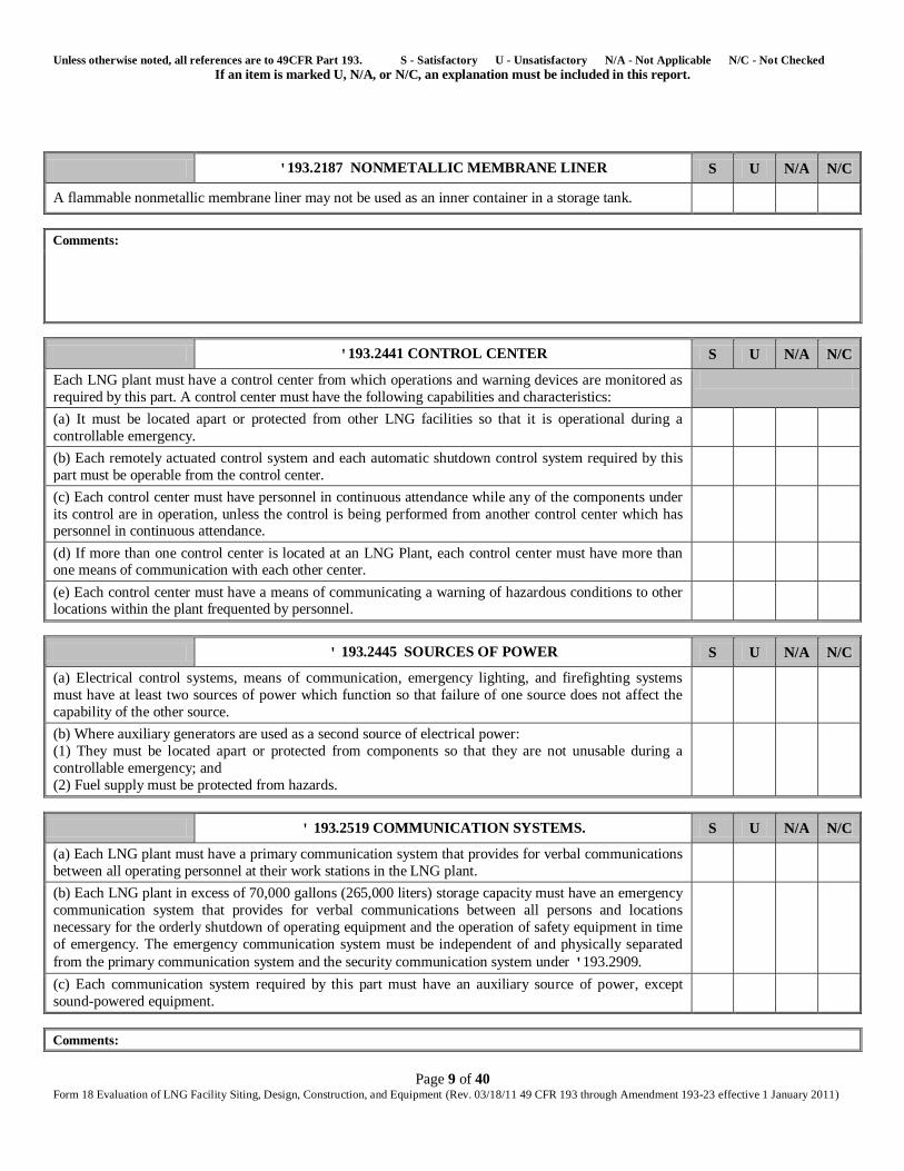
'193.2187 NONMETALLIC MEMBRANE LINER S U N/A N/C
A flammable nonmetallic membrane liner may not be used as an inner container in a storage tank.
Comments:
'193.2441 CONTROL CENTER S U N/A N/C
Each LNG plant must have a control center from which operations and warning devices are monitored as
required by this part. A control center must have the following capabilities and characteristics:
(a) It must be located apart or protected from other LNG facilities so that it is operational during a
controllable emergency.
(b) Each remotely actuated control system and each automatic shutdown control system required by this
part must be operable from the control center.
(c) Each control center must have personnel in continuous attendance while any of the components under
its control are in operation, unless the control is being performed from another control center which has personnel in continuous attendance.
(d) If more than one control center is located at an LNG Plant, each control center must have more than one means of communication with each other center.
(e) Each control center must have a means of communicating a warning of hazardous conditions to other locations within the plant frequented by personnel.
' 193.2445 SOURCES OF POWER S U N/A N/C
(a) Electrical control systems, means of communication, emergency lighting, and firefighting systems
must have at least two sources of power which function so that failure of one source does not affect the
capability of the other source.
(b) Where auxiliary generators are used as a second source of electrical power:
(1) They must be located apart or protected from components so that they are not unusable during a
controllable emergency; and
(2) Fuel supply must be protected from hazards.
' 193.2519 COMMUNICATION SYSTEMS. S U N/A N/C
(a) Each LNG plant must have a primary communication system that provides for verbal communications
between all operating personnel at their work stations in the LNG plant.
(b) Each LNG plant in excess of 70,000 gallons (265,000 liters) storage capacity must have an emergency
communication system that provides for verbal communications between all persons and locations
necessary for the orderly shutdown of operating equipment and the operation of safety equipment in time
of emergency. The emergency communication system must be independent of and physically separated
from the primary communication system and the security communication system under '193.2909.
(c) Each communication system required by this part must have an auxiliary source of power, except
sound-powered equipment.
Comments:
Unless otherwise noted, all references are to 49CFR Part 193. S - Satisfactory U - Unsatisfactory N/A - Not Applicable N/C - Not Checked If an item is marked U, N/A, or N/C, an explanation must be included in this report.
Page 10 of 40 Form 18 Evaluation of LNG Facility Siting, Design, Construction, and Equipment (Rev. 03/18/11 49 CFR 193 through Amendment 193-23 effective 1 January 2011)
Comments:
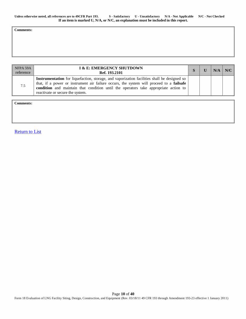
NFPA 59A
reference I & E: EMERGENCY SHUTDOWN
Ref. 193.2101 S U N/A N/C
7.5
Instrumentation for liquefaction, storage, and vaporization facilities shall be designed so
that, if a power or instrument air failure occurs, the system will proceed to a failsafe
condition and maintain that condition until the operators take appropriate action to
reactivate or secure the system.
Comments:
Return to List
Unless otherwise noted, all references are to 49CFR Part 193. S - Satisfactory U - Unsatisfactory N/A - Not Applicable N/C - Not Checked If an item is marked U, N/A, or N/C, an explanation must be included in this report.
Page 11 of 40 Form 18 Evaluation of LNG Facility Siting, Design, Construction, and Equipment (Rev. 03/18/11 49 CFR 193 through Amendment 193-23 effective 1 January 2011)
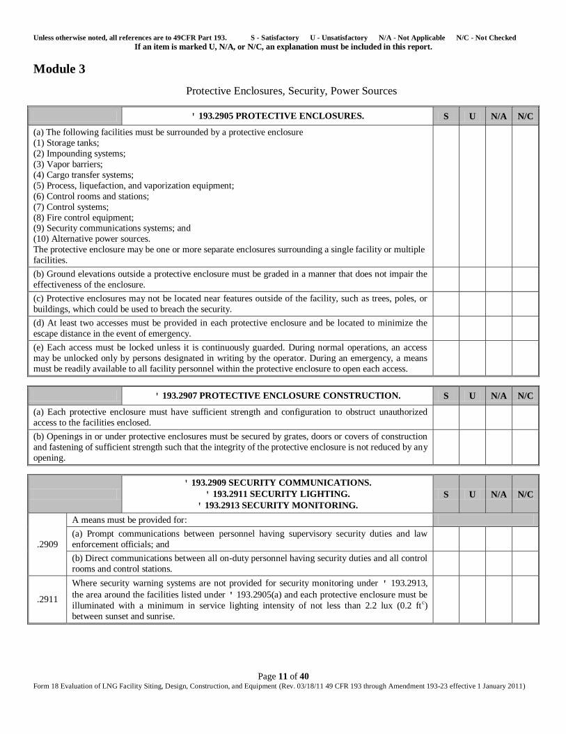
Module 3
Protective Enclosures, Security, Power Sources
' 193.2905 PROTECTIVE ENCLOSURES. S U N/A N/C
(a) The following facilities must be surrounded by a protective enclosure
(1) Storage tanks;
(2) Impounding systems;
(3) Vapor barriers;
(4) Cargo transfer systems;
(5) Process, liquefaction, and vaporization equipment;
(6) Control rooms and stations;
(7) Control systems;
(8) Fire control equipment; (9) Security communications systems; and
(10) Alternative power sources.
The protective enclosure may be one or more separate enclosures surrounding a single facility or multiple
facilities.
(b) Ground elevations outside a protective enclosure must be graded in a manner that does not impair the
effectiveness of the enclosure.
(c) Protective enclosures may not be located near features outside of the facility, such as trees, poles, or
buildings, which could be used to breach the security.
(d) At least two accesses must be provided in each protective enclosure and be located to minimize the
escape distance in the event of emergency.
(e) Each access must be locked unless it is continuously guarded. During normal operations, an access
may be unlocked only by persons designated in writing by the operator. During an emergency, a means
must be readily available to all facility personnel within the protective enclosure to open each access.
' 193.2907 PROTECTIVE ENCLOSURE CONSTRUCTION. S U N/A N/C
(a) Each protective enclosure must have sufficient strength and configuration to obstruct unauthorized
access to the facilities enclosed.
(b) Openings in or under protective enclosures must be secured by grates, doors or covers of construction
and fastening of sufficient strength such that the integrity of the protective enclosure is not reduced by any
opening.
' 193.2909 SECURITY COMMUNICATIONS.
' 193.2911 SECURITY LIGHTING.
' 193.2913 SECURITY MONITORING.
S U N/A N/C
.2909
A means must be provided for:
(a) Prompt communications between personnel having supervisory security duties and law
enforcement officials; and
(b) Direct communications between all on-duty personnel having security duties and all control
rooms and control stations.
.2911
Where security warning systems are not provided for security monitoring under ' 193.2913,
the area around the facilities listed under ' 193.2905(a) and each protective enclosure must be
illuminated with a minimum in service lighting intensity of not less than 2.2 lux (0.2 ftc)
between sunset and sunrise.

Unless otherwise noted, all references are to 49CFR Part 193. S - Satisfactory U - Unsatisfactory N/A - Not Applicable N/C - Not Checked If an item is marked U, N/A, or N/C, an explanation must be included in this report.
Page 12 of 40 Form 18 Evaluation of LNG Facility Siting, Design, Construction, and Equipment (Rev. 03/18/11 49 CFR 193 through Amendment 193-23 effective 1 January 2011)
' 193.2909 SECURITY COMMUNICATIONS.
' 193.2911 SECURITY LIGHTING.
' 193.2913 SECURITY MONITORING.
S U N/A N/C
.2913
Each protective enclosure and the area around each facility listed in ' 193.2905(a) must be
monitored for the presence of unauthorized persons. Monitoring must be by visual observation
in accordance with the schedule in the security procedures under ' 193.2903(a) or by security
warning systems that continuously transmit data to an attended location. At an LNG plant with
less than 40,000 m3 (250,000 bbl) of storage capacity, only the protective enclosure must be
monitored.
' 193.2915 ALTERNATIVE POWER SOURCES. S U N/A N/C
An alternative source of power that meets the requirements of ' 193.2445 must be provided for security
lighting and security monitoring and warning systems required under '' 193.2911 and 193.2913.
Comments:
Return to List
Unless otherwise noted, all references are to 49CFR Part 193. S - Satisfactory U - Unsatisfactory N/A - Not Applicable N/C - Not Checked If an item is marked U, N/A, or N/C, an explanation must be included in this report.
Page 13 of 40 Form 18 Evaluation of LNG Facility Siting, Design, Construction, and Equipment (Rev. 03/18/11 49 CFR 193 through Amendment 193-23 effective 1 January 2011)
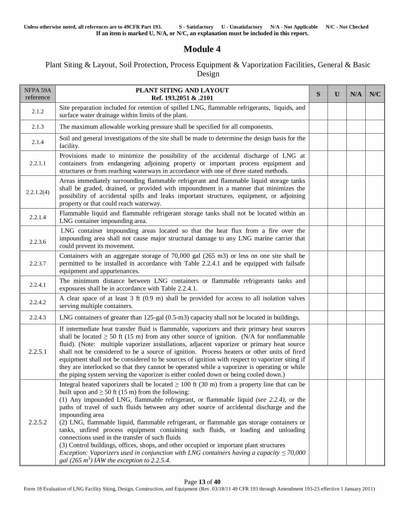
Module 4
Plant Siting & Layout, Soil Protection, Process Equipment & Vaporization Facilities, General & Basic
Design
NFPA 59A
reference PLANT SITING AND LAYOUT
Ref. 193.2051 & .2101 S U N/A N/C
2.1.2 Site preparation included for retention of spilled LNG, flammable refrigerants, liquids, and surface water drainage within limits of the plant.
2.1.3 The maximum allowable working pressure shall be specified for all components.
2.1.4 Soil and general investigations of the site shall be made to determine the design basis for the
facility.
2.2.1.1 Provisions made to minimize the possibility of the accidental discharge of LNG at
containers from endangering adjoining property or important process equipment and
structures or from reaching waterways in accordance with one of three stated methods.
2.2.1.2(4)
Areas immediately surrounding flammable refrigerant and flammable liquid storage tanks
shall be graded, drained, or provided with impoundment in a manner that minimizes the possibility of accidental spills and leaks important structures, equipment, or adjoining
property or that could reach waterway.
2.2.1.4 Flammable liquid and flammable refrigerant storage tanks shall not be located within an
LNG container impounding area.
2.2.3.6
LNG container impounding areas located so that the heat flux from a fire over the
impounding area shall not cause major structural damage to any LNG marine carrier that
could prevent its movement.
2.2.3.7
Containers with an aggregate storage of 70,000 gal (265 m3) or less on one site shall be
permitted to be installed in accordance with Table 2.2.4.1 and be equipped with failsafe
equipment and appurtenances.
2.2.4.1 The minimum distance between LNG containers or flammable refrigerants tanks and
exposures shall be in accordance with Table 2.2.4.1.
2.2.4.2 A clear space of at least 3 ft (0.9 m) shall be provided for access to all isolation valves
serving multiple containers.
2.2.4.3 LNG containers of greater than 125-gal (0.5-m3) capacity shall not be located in buildings.
2.2.5.1
If intermediate heat transfer fluid is flammable, vaporizers and their primary heat sources
shall be located ≥ 50 ft (15 m) from any other source of ignition. (N/A for nonflammable
fluid). (Note: multiple vaporizer installations, adjacent vaporizer or primary heat source
shall not be considered to be a source of ignition. Process heaters or other units of fired
equipment shall not be considered to be sources of ignition with respect to vaporizer siting if
they are interlocked so that they cannot be operated while a vaporizer is operating or while
the piping system serving the vaporizer is either cooled down or being cooled down.)
2.2.5.2
Integral heated vaporizers shall be located ≥ 100 ft (30 m) from a property line that can be
built upon and ≥ 50 ft (15 m) from the following:
(1) Any impounded LNG, flammable refrigerant, or flammable liquid (see 2.2.4), or the
paths of travel of such fluids between any other source of accidental discharge and the
impounding area (2) LNG, flammable liquid, flammable refrigerant, or flammable gas storage containers or
tanks, unfired process equipment containing such fluids, or loading and unloading
connections used in the transfer of such fluids
(3) Control buildings, offices, shops, and other occupied or important plant structures
Exception: Vaporizers used in conjunction with LNG containers having a capacity ≤ 70,000
gal (265 m3) IAW the exception to 2.2.5.4.
Unless otherwise noted, all references are to 49CFR Part 193. S - Satisfactory U - Unsatisfactory N/A - Not Applicable N/C - Not Checked If an item is marked U, N/A, or N/C, an explanation must be included in this report.
Page 14 of 40 Form 18 Evaluation of LNG Facility Siting, Design, Construction, and Equipment (Rev. 03/18/11 49 CFR 193 through Amendment 193-23 effective 1 January 2011)
NFPA 59A
reference PLANT SITING AND LAYOUT
Ref. 193.2051 & .2101 S U N/A N/C
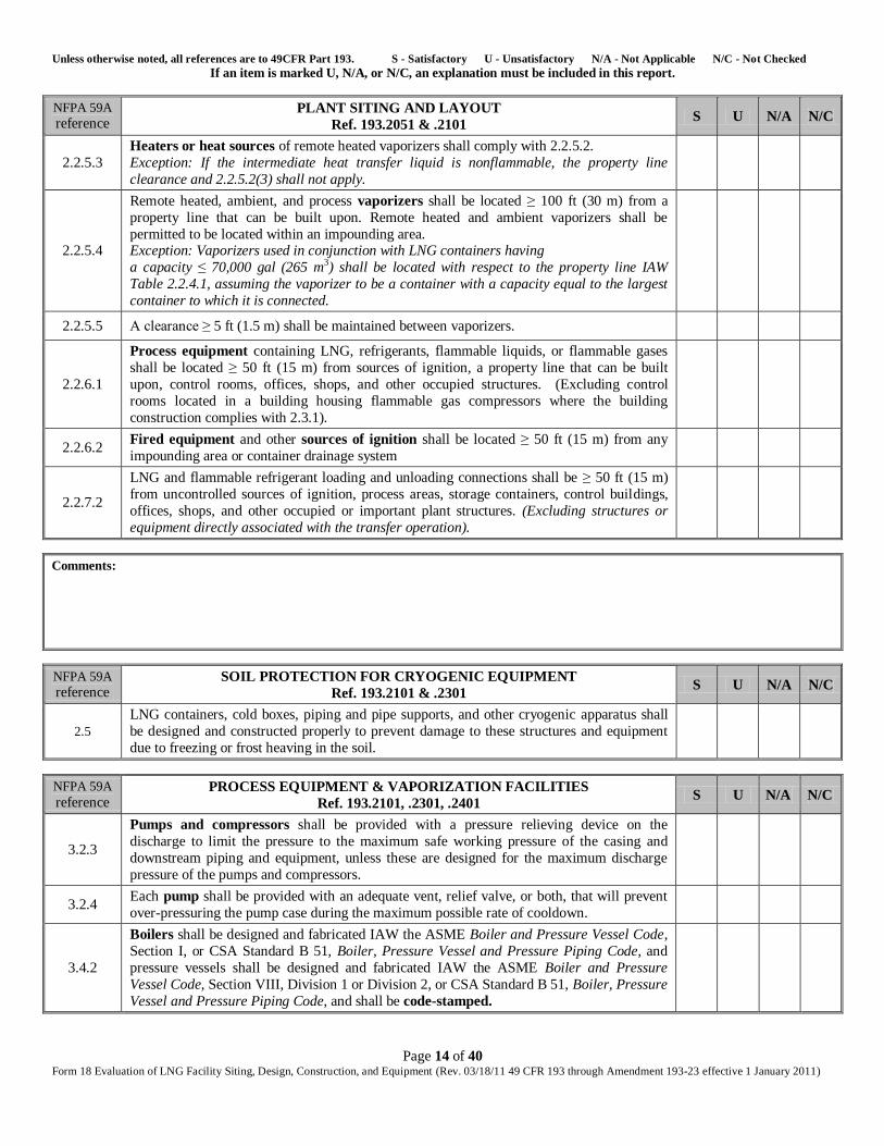
2.2.5.3
Heaters or heat sources of remote heated vaporizers shall comply with 2.2.5.2.
Exception: If the intermediate heat transfer liquid is nonflammable, the property line
clearance and 2.2.5.2(3) shall not apply.
2.2.5.4
Remote heated, ambient, and process vaporizers shall be located ≥ 100 ft (30 m) from a
property line that can be built upon. Remote heated and ambient vaporizers shall be
permitted to be located within an impounding area. Exception: Vaporizers used in conjunction with LNG containers having
a capacity ≤ 70,000 gal (265 m3) shall be located with respect to the property line IAW
Table 2.2.4.1, assuming the vaporizer to be a container with a capacity equal to the largest
container to which it is connected.
2.2.5.5 A clearance ≥ 5 ft (1.5 m) shall be maintained between vaporizers.
2.2.6.1
Process equipment containing LNG, refrigerants, flammable liquids, or flammable gases
shall be located ≥ 50 ft (15 m) from sources of ignition, a property line that can be built
upon, control rooms, offices, shops, and other occupied structures. (Excluding control
rooms located in a building housing flammable gas compressors where the building
construction complies with 2.3.1).
2.2.6.2 Fired equipment and other sources of ignition shall be located ≥ 50 ft (15 m) from any
impounding area or container drainage system
2.2.7.2
LNG and flammable refrigerant loading and unloading connections shall be ≥ 50 ft (15 m)
from uncontrolled sources of ignition, process areas, storage containers, control buildings,
offices, shops, and other occupied or important plant structures. (Excluding structures or
equipment directly associated with the transfer operation).
Comments:
NFPA 59A
reference SOIL PROTECTION FOR CRYOGENIC EQUIPMENT
Ref. 193.2101 & .2301 S U N/A N/C
2.5
LNG containers, cold boxes, piping and pipe supports, and other cryogenic apparatus shall
be designed and constructed properly to prevent damage to these structures and equipment
due to freezing or frost heaving in the soil.
NFPA 59A
reference PROCESS EQUIPMENT & VAPORIZATION FACILITIES
Ref. 193.2101, .2301, .2401 S U N/A N/C
3.2.3
Pumps and compressors shall be provided with a pressure relieving device on the
discharge to limit the pressure to the maximum safe working pressure of the casing and
downstream piping and equipment, unless these are designed for the maximum discharge
pressure of the pumps and compressors.
3.2.4 Each pump shall be provided with an adequate vent, relief valve, or both, that will prevent
over-pressuring the pump case during the maximum possible rate of cooldown.
3.4.2
Boilers shall be designed and fabricated IAW the ASME Boiler and Pressure Vessel Code,
Section I, or CSA Standard B 51, Boiler, Pressure Vessel and Pressure Piping Code, and
pressure vessels shall be designed and fabricated IAW the ASME Boiler and Pressure
Vessel Code, Section VIII, Division 1 or Division 2, or CSA Standard B 51, Boiler, Pressure
Vessel and Pressure Piping Code, and shall be code-stamped.
Unless otherwise noted, all references are to 49CFR Part 193. S - Satisfactory U - Unsatisfactory N/A - Not Applicable N/C - Not Checked If an item is marked U, N/A, or N/C, an explanation must be included in this report.
Page 15 of 40 Form 18 Evaluation of LNG Facility Siting, Design, Construction, and Equipment (Rev. 03/18/11 49 CFR 193 through Amendment 193-23 effective 1 January 2011)
NFPA 59A
reference PROCESS EQUIPMENT & VAPORIZATION FACILITIES
Ref. 193.2101, .2301, .2401 S U N/A N/C
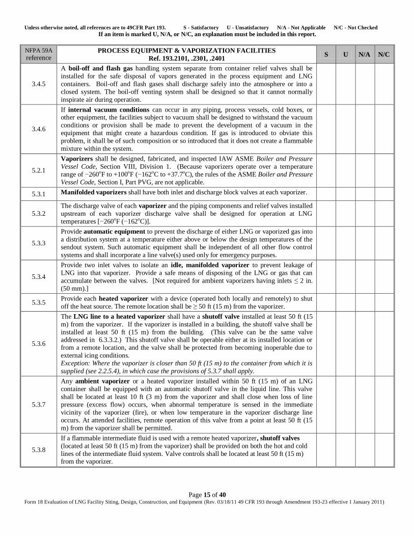
3.4.5
A boil-off and flash gas handling system separate from container relief valves shall be
installed for the safe disposal of vapors generated in the process equipment and LNG
containers. Boil-off and flash gases shall discharge safely into the atmosphere or into a
closed system. The boil-off venting system shall be designed so that it cannot normally
inspirate air during operation.
3.4.6
If internal vacuum conditions can occur in any piping, process vessels, cold boxes, or other equipment, the facilities subject to vacuum shall be designed to withstand the vacuum
conditions or provision shall be made to prevent the development of a vacuum in the
equipment that might create a hazardous condition. If gas is introduced to obviate this
problem, it shall be of such composition or so introduced that it does not create a flammable
mixture within the system.
5.2.1
Vaporizers shall be designed, fabricated, and inspected IAW ASME Boiler and Pressure
Vessel Code, Section VIII, Division 1. (Because vaporizers operate over a temperature
range of −260oF to +100oF (−162oC to +37.7oC), the rules of the ASME Boiler and Pressure
Vessel Code, Section I, Part PVG, are not applicable.
5.3.1 Manifolded vaporizers shall have both inlet and discharge block valves at each vaporizer.
5.3.2
The discharge valve of each vaporizer and the piping components and relief valves installed
upstream of each vaporizer discharge valve shall be designed for operation at LNG
temperatures [−260oF (−162oC)].
5.3.3
Provide automatic equipment to prevent the discharge of either LNG or vaporized gas into
a distribution system at a temperature either above or below the design temperatures of the
sendout system. Such automatic equipment shall be independent of all other flow control
systems and shall incorporate a line valve(s) used only for emergency purposes.
5.3.4
Provide two inlet valves to isolate an idle, manifolded vaporizer to prevent leakage of
LNG into that vaporizer. Provide a safe means of disposing of the LNG or gas that can
accumulate between the valves. [Not required for ambient vaporizers having inlets ≤ 2 in.
(50 mm).]
5.3.5 Provide each heated vaporizer with a device (operated both locally and remotely) to shut
off the heat source. The remote location shall be ≥ 50 ft (15 m) from the vaporizer.
5.3.6
The LNG line to a heated vaporizer shall have a shutoff valve installed at least 50 ft (15
m) from the vaporizer. If the vaporizer is installed in a building, the shutoff valve shall be
installed at least 50 ft (15 m) from the building. (This valve can be the same valve addressed in 6.3.3.2.) This shutoff valve shall be operable either at its installed location or
from a remote location, and the valve shall be protected from becoming inoperable due to
external icing conditions.
Exception: Where the vaporizer is closer than 50 ft (15 m) to the container from which it is
supplied (see 2.2.5.4), in which case the provisions of 5.3.7 shall apply.
5.3.7
Any ambient vaporizer or a heated vaporizer installed within 50 ft (15 m) of an LNG
container shall be equipped with an automatic shutoff valve in the liquid line. This valve
shall be located at least 10 ft (3 m) from the vaporizer and shall close when loss of line
pressure (excess flow) occurs, when abnormal temperature is sensed in the immediate
vicinity of the vaporizer (fire), or when low temperature in the vaporizer discharge line
occurs. At attended facilities, remote operation of this valve from a point at least 50 ft (15
m) from the vaporizer shall be permitted.
5.3.8
If a flammable intermediate fluid is used with a remote heated vaporizer, shutoff valves
(located at least 50 ft (15 m) from the vaporizer) shall be provided on both the hot and cold
lines of the intermediate fluid system. Valve controls shall be located at least 50 ft (15 m) from the vaporizer.
Unless otherwise noted, all references are to 49CFR Part 193. S - Satisfactory U - Unsatisfactory N/A - Not Applicable N/C - Not Checked If an item is marked U, N/A, or N/C, an explanation must be included in this report.
Page 16 of 40 Form 18 Evaluation of LNG Facility Siting, Design, Construction, and Equipment (Rev. 03/18/11 49 CFR 193 through Amendment 193-23 effective 1 January 2011)
NFPA 59A
reference PROCESS EQUIPMENT & VAPORIZATION FACILITIES
Ref. 193.2101, .2301, .2401 S U N/A N/C
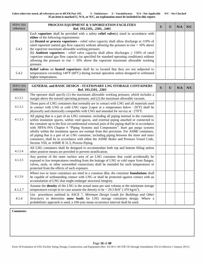
5.4.1
Each vaporizer shall be provided with a safety relief valve(s) sized in accordance with
either of the following requirements:
(a) Heated or process vaporizers - relief valve capacity shall allow discharge at 110% of
rated vaporizer natural gas flow capacity without allowing the pressure to rise > 10% above
the vaporizer maximum allowable working pressure. (b) Ambient vaporizers - relief valve capacity shall allow discharges ≥ 150% of rated
vaporizer natural gas flow capacity (as specified for standard operating conditions) without
allowing the pressure to rise > 10% above the vaporizer maximum allowable working
pressure.
5.4.2
Relief valves on heated vaporizers shall be so located that they are not subjected to
temperatures exceeding 140oF (60oC) during normal operation unless designed to withstand
higher temperatures.
NFPA 59A
reference GENERAL and BASIC DESIGN - STATIONARY LNG STORAGE CONTAINERS
Ref. 193.2101, .2303 S U N/A N/C
4.1.2.1
The operator shall specify (1) the maximum allowable working pressure, which includes a
margin above the normal operating pressure, and (2) the maximum allowable vacuum.
4.1.2.2
Those parts of LNG containers that normally are in contact with LNG and all materials used
in contact with LNG or cold LNG vapor [vapor at a temperature below −20oF] shall be
physically and chemically compatible with LNG and intended for service at −270oF.
4.1.2.3
All piping that is a part of an LNG container, including all piping internal to the container,
within insulation spaces, within void spaces, and external piping attached or connected to
the container up to the first circumferential external joint of the piping shall be in accordance
with NFPA-59A Chapter 6 ―Piping Systems and Components‖. Inert gas purge systems wholly within the insulation spaces are exempt from this provision. For ASME containers,
all piping that is a part of an LNG container, including piping between the inner and outer
containers, shall be in accordance with either the ASME Boiler and Pressure Vessel Code,
Section VIII, or ASME B 31.3, Process Piping.
4.1.2.4
All LNG containers shall be designed to accommodate both top and bottom filling unless
other positive means are provided to prevent stratification.
4.1.2.5
Any portion of the outer surface area of an LNG container that could accidentally be
exposed to low temperatures resulting from the leakage of LNG or cold vapor from flanges,
valves, seals, or other nonwelded connections shall be intended for such temperatures or
protected from the effects of such exposure.
4.1.2.6
Where two or more containers are sited in a common dike, the container foundations shall
be capable of withstanding contact with LNG or shall be protected against contact with an
accumulation of LNG that might endanger structural integrity.
4.1.2.7
Assume the density of the LNG is the actual mass per unit volume at the minimum storage
temperatures except in no case assume the density to be < 29.3 lb/ft3 ( 470 kg/m3).
4.1.4
Use procedures outlined in ASCE 7, Minimum Design Loads for Buildings and Other
Structures to determine snow loads for LNG storage containers design. Where a
probabilistic approach is used, a 100-year mean occurrence interval shall be used.
Comments:
Unless otherwise noted, all references are to 49CFR Part 193. S - Satisfactory U - Unsatisfactory N/A - Not Applicable N/C - Not Checked If an item is marked U, N/A, or N/C, an explanation must be included in this report.
Page 17 of 40 Form 18 Evaluation of LNG Facility Siting, Design, Construction, and Equipment (Rev. 03/18/11 49 CFR 193 through Amendment 193-23 effective 1 January 2011)
Return to List
Unless otherwise noted, all references are to 49CFR Part 193. S - Satisfactory U - Unsatisfactory N/A - Not Applicable N/C - Not Checked If an item is marked U, N/A, or N/C, an explanation must be included in this report.
Page 18 of 40 Form 18 Evaluation of LNG Facility Siting, Design, Construction, and Equipment (Rev. 03/18/11 49 CFR 193 through Amendment 193-23 effective 1 January 2011)
Module 5
Seismic Design, Container Insulation, Foundations, API 620 Tanks
NFPA 59A
reference SEISMIC DESIGN - STATIONARY LNG STORAGE CONTAINERS
Ref. 193.2101 & .2301 S U N/A N/C
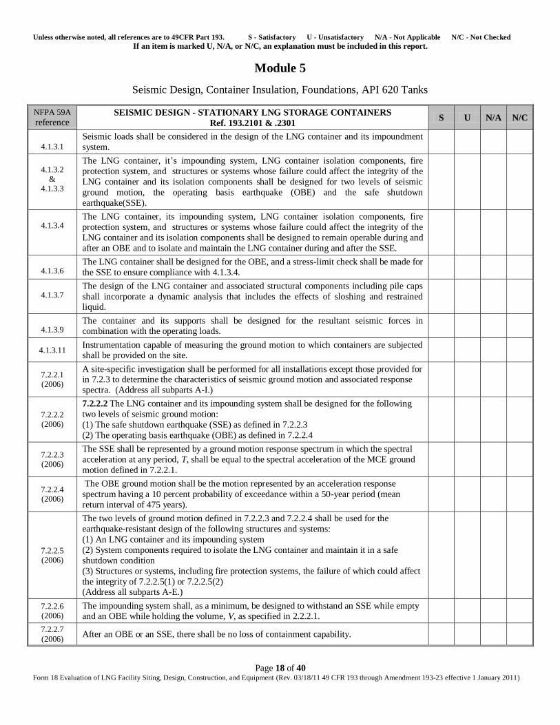
4.1.3.1
Seismic loads shall be considered in the design of the LNG container and its impoundment
system.
4.1.3.2
& 4.1.3.3
The LNG container, it’s impounding system, LNG container isolation components, fire
protection system, and structures or systems whose failure could affect the integrity of the
LNG container and its isolation components shall be designed for two levels of seismic
ground motion, the operating basis earthquake (OBE) and the safe shutdown
earthquake(SSE).
4.1.3.4
The LNG container, its impounding system, LNG container isolation components, fire
protection system, and structures or systems whose failure could affect the integrity of the
LNG container and its isolation components shall be designed to remain operable during and
after an OBE and to isolate and maintain the LNG container during and after the SSE.
4.1.3.6
The LNG container shall be designed for the OBE, and a stress-limit check shall be made for
the SSE to ensure compliance with 4.1.3.4.
4.1.3.7
The design of the LNG container and associated structural components including pile caps
shall incorporate a dynamic analysis that includes the effects of sloshing and restrained liquid.
4.1.3.9
The container and its supports shall be designed for the resultant seismic forces in combination with the operating loads.
4.1.3.11 Instrumentation capable of measuring the ground motion to which containers are subjected shall be provided on the site.
7.2.2.1 (2006)
A site-specific investigation shall be performed for all installations except those provided for in 7.2.3 to determine the characteristics of seismic ground motion and associated response
spectra. (Address all subparts A-I.)
7.2.2.2 (2006)
7.2.2.2 The LNG container and its impounding system shall be designed for the following
two levels of seismic ground motion:
(1) The safe shutdown earthquake (SSE) as defined in 7.2.2.3
(2) The operating basis earthquake (OBE) as defined in 7.2.2.4
7.2.2.3 (2006)
The SSE shall be represented by a ground motion response spectrum in which the spectral
acceleration at any period, T, shall be equal to the spectral acceleration of the MCE ground
motion defined in 7.2.2.1.
7.2.2.4 (2006)
The OBE ground motion shall be the motion represented by an acceleration response
spectrum having a 10 percent probability of exceedance within a 50-year period (mean
return interval of 475 years).
7.2.2.5 (2006)
The two levels of ground motion defined in 7.2.2.3 and 7.2.2.4 shall be used for the
earthquake-resistant design of the following structures and systems:
(1) An LNG container and its impounding system
(2) System components required to isolate the LNG container and maintain it in a safe
shutdown condition
(3) Structures or systems, including fire protection systems, the failure of which could affect
the integrity of 7.2.2.5(1) or 7.2.2.5(2) (Address all subparts A-E.)
7.2.2.6 (2006)
The impounding system shall, as a minimum, be designed to withstand an SSE while empty and an OBE while holding the volume, V, as specified in 2.2.2.1.
7.2.2.7
(2006) After an OBE or an SSE, there shall be no loss of containment capability.
Unless otherwise noted, all references are to 49CFR Part 193. S - Satisfactory U - Unsatisfactory N/A - Not Applicable N/C - Not Checked If an item is marked U, N/A, or N/C, an explanation must be included in this report.
Page 19 of 40 Form 18 Evaluation of LNG Facility Siting, Design, Construction, and Equipment (Rev. 03/18/11 49 CFR 193 through Amendment 193-23 effective 1 January 2011)
NFPA 59A
reference SEISMIC DESIGN - STATIONARY LNG STORAGE CONTAINERS
Ref. 193.2101 & .2301 S U N/A N/C
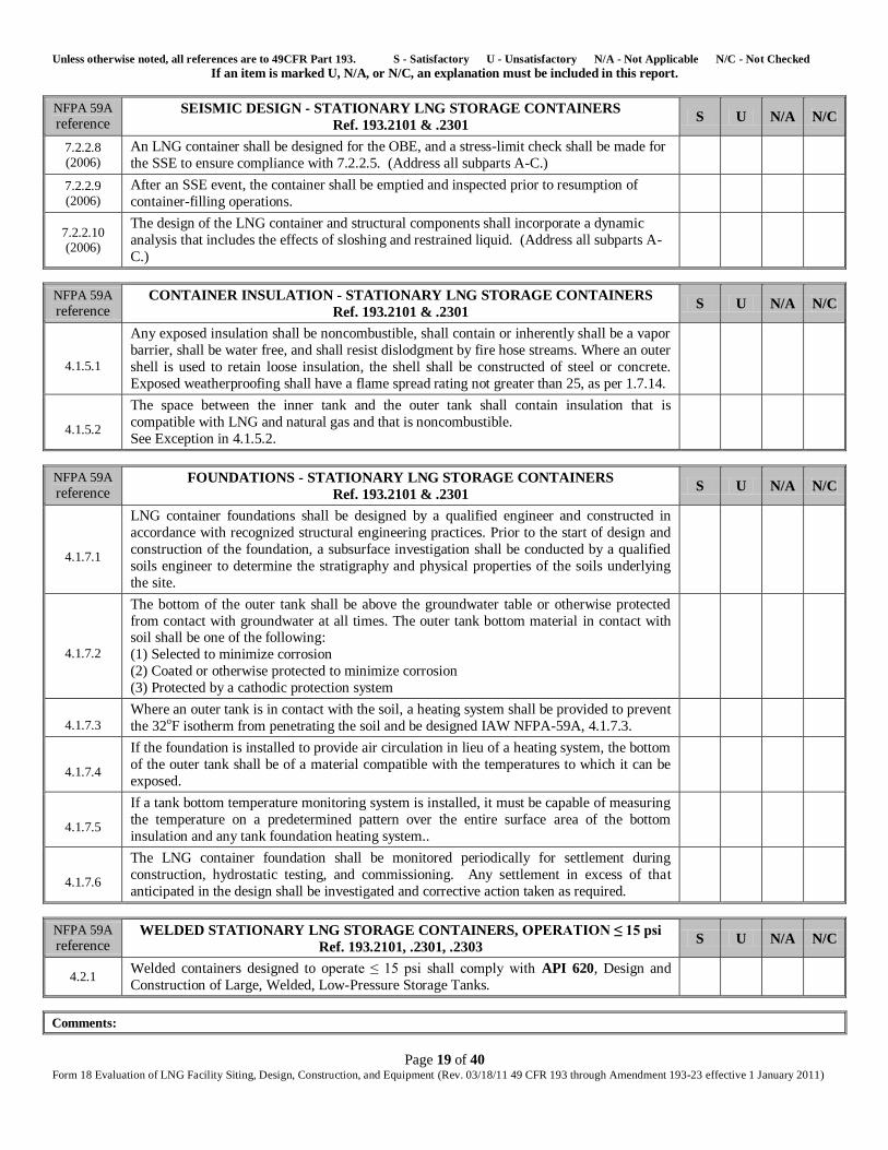
7.2.2.8 (2006)
An LNG container shall be designed for the OBE, and a stress-limit check shall be made for
the SSE to ensure compliance with 7.2.2.5. (Address all subparts A-C.)
7.2.2.9 (2006)
After an SSE event, the container shall be emptied and inspected prior to resumption of
container-filling operations.
7.2.2.10 (2006)
The design of the LNG container and structural components shall incorporate a dynamic
analysis that includes the effects of sloshing and restrained liquid. (Address all subparts A-
C.)
NFPA 59A
reference CONTAINER INSULATION - STATIONARY LNG STORAGE CONTAINERS
Ref. 193.2101 & .2301 S U N/A N/C
4.1.5.1
Any exposed insulation shall be noncombustible, shall contain or inherently shall be a vapor
barrier, shall be water free, and shall resist dislodgment by fire hose streams. Where an outer
shell is used to retain loose insulation, the shell shall be constructed of steel or concrete.
Exposed weatherproofing shall have a flame spread rating not greater than 25, as per 1.7.14.
4.1.5.2
The space between the inner tank and the outer tank shall contain insulation that is
compatible with LNG and natural gas and that is noncombustible.
See Exception in 4.1.5.2.
NFPA 59A
reference FOUNDATIONS - STATIONARY LNG STORAGE CONTAINERS
Ref. 193.2101 & .2301 S U N/A N/C
4.1.7.1
LNG container foundations shall be designed by a qualified engineer and constructed in
accordance with recognized structural engineering practices. Prior to the start of design and
construction of the foundation, a subsurface investigation shall be conducted by a qualified
soils engineer to determine the stratigraphy and physical properties of the soils underlying
the site.
4.1.7.2
The bottom of the outer tank shall be above the groundwater table or otherwise protected
from contact with groundwater at all times. The outer tank bottom material in contact with soil shall be one of the following:
(1) Selected to minimize corrosion
(2) Coated or otherwise protected to minimize corrosion
(3) Protected by a cathodic protection system
4.1.7.3
Where an outer tank is in contact with the soil, a heating system shall be provided to prevent
the 32oF isotherm from penetrating the soil and be designed IAW NFPA-59A, 4.1.7.3.
4.1.7.4
If the foundation is installed to provide air circulation in lieu of a heating system, the bottom
of the outer tank shall be of a material compatible with the temperatures to which it can be
exposed.
4.1.7.5
If a tank bottom temperature monitoring system is installed, it must be capable of measuring
the temperature on a predetermined pattern over the entire surface area of the bottom
insulation and any tank foundation heating system..
4.1.7.6
The LNG container foundation shall be monitored periodically for settlement during
construction, hydrostatic testing, and commissioning. Any settlement in excess of that
anticipated in the design shall be investigated and corrective action taken as required.
NFPA 59A
reference WELDED STATIONARY LNG STORAGE CONTAINERS, OPERATION ≤ 15 psi
Ref. 193.2101, .2301, .2303 S U N/A N/C
4.2.1 Welded containers designed to operate ≤ 15 psi shall comply with API 620, Design and
Construction of Large, Welded, Low-Pressure Storage Tanks.
Comments:
Unless otherwise noted, all references are to 49CFR Part 193. S - Satisfactory U - Unsatisfactory N/A - Not Applicable N/C - Not Checked If an item is marked U, N/A, or N/C, an explanation must be included in this report.
Page 20 of 40 Form 18 Evaluation of LNG Facility Siting, Design, Construction, and Equipment (Rev. 03/18/11 49 CFR 193 through Amendment 193-23 effective 1 January 2011)
Comments:
Return to List
Unless otherwise noted, all references are to 49CFR Part 193. S - Satisfactory U - Unsatisfactory N/A - Not Applicable N/C - Not Checked If an item is marked U, N/A, or N/C, an explanation must be included in this report.
Page 21 of 40 Form 18 Evaluation of LNG Facility Siting, Design, Construction, and Equipment (Rev. 03/18/11 49 CFR 193 through Amendment 193-23 effective 1 January 2011)
Module 6
High Pressure Tanks (>15 psi)
NFPA 59A
reference STATIONARY LNG STORAGE TANKS DESIGNED FOR OPERATION at >15 psi
Ref. 193.2101, .2301, .2303, .2321 S U N/A N/C
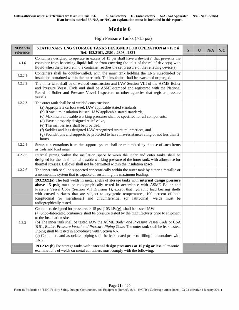
4.1.6 Containers designed to operate in excess of 15 psi shall have a device(s) that prevents the
container from becoming liquid full or from covering the inlet of the relief device(s) with
liquid when the pressure in the container reaches the set pressure of the relieving device(s).
4.2.2.1 Containers shall be double-walled, with the inner tank holding the LNG surrounded by
insulation contained within the outer tank. The insulation shall be evacuated or purged.
4.2.2.2 The inner tank shall be of welded construction and IAW Section VIII of the ASME Boiler
and Pressure Vessel Code and shall be ASME-stamped and registered with the National
Board of Boiler and Pressure Vessel Inspectors or other agencies that register pressure
vessels.
4.2.2.3 The outer tank shall be of welded construction:
(a) Appropriate carbon steel, IAW applicable stated standards,
(b) If vacuum insulation is used, IAW applicable stated standards,
(c) Maximum allowable working pressures shall be specified for all components, (d) Have a properly designed relief valve,
(e) Thermal barriers shall be provided,
(f) Saddles and legs designed IAW recognized structural practices, and
(g) Foundations and supports be protected to have fire-resistance rating of not less than 2
hours.
4.2.2.4 Stress concentrations from the support system shall be minimized by the use of such items
as pads and load rings.
4.2.2.5 Internal piping within the insulation space between the inner and outer tanks shall be
designed for the maximum allowable working pressure of the inner tank, with allowance for
thermal stresses. Bellows shall not be permitted within the insulation space.
4.2.2.6 The inner tank shall be supported concentrically within the outer tank by either a metallic or
a nonmetallic system that is capable of sustaining the maximum loading.
193.2321(a) The butt welds in metal shells of storage tanks with internal design pressure
above 15 psig must be radiographically tested in accordance with ASME Boiler and
Pressure Vessel Code (Section VII Division 1), except that hydraulic load bearing shells
with curved surfaces that are subject to cryogenic temperatures, 100 percent of both
longitudinal (or meridional) and circumferential (or latitudinal) welds must be
radiographically tested.
4.5.2
Containers designed for pressures > 15 psi [103 kPa(g)] shall be tested IAW:
(a) Shop-fabricated containers shall be pressure tested by the manufacturer prior to shipment
to the installation site. (b) The inner tank shall be tested IAW the ASME Boiler and Pressure Vessel Code or CSA
B 51, Boiler, Pressure Vessel and Pressure Piping Code. The outer tank shall be leak tested.
Piping shall be tested in accordance with Section 6.6.
(c) Containers and associated piping shall be leak tested prior to filling the container with
LNG.
193.2321(b) For storage tanks with internal design pressures at 15 psig or less, ultrasonic
examinations of welds on metal containers must comply with the following:
Unless otherwise noted, all references are to 49CFR Part 193. S - Satisfactory U - Unsatisfactory N/A - Not Applicable N/C - Not Checked If an item is marked U, N/A, or N/C, an explanation must be included in this report.
Page 22 of 40 Form 18 Evaluation of LNG Facility Siting, Design, Construction, and Equipment (Rev. 03/18/11 49 CFR 193 through Amendment 193-23 effective 1 January 2011)
NFPA 59A
reference STATIONARY LNG STORAGE TANKS DESIGNED FOR OPERATION at >15 psi
Ref. 193.2101, .2301, .2303, .2321 S U N/A N/C
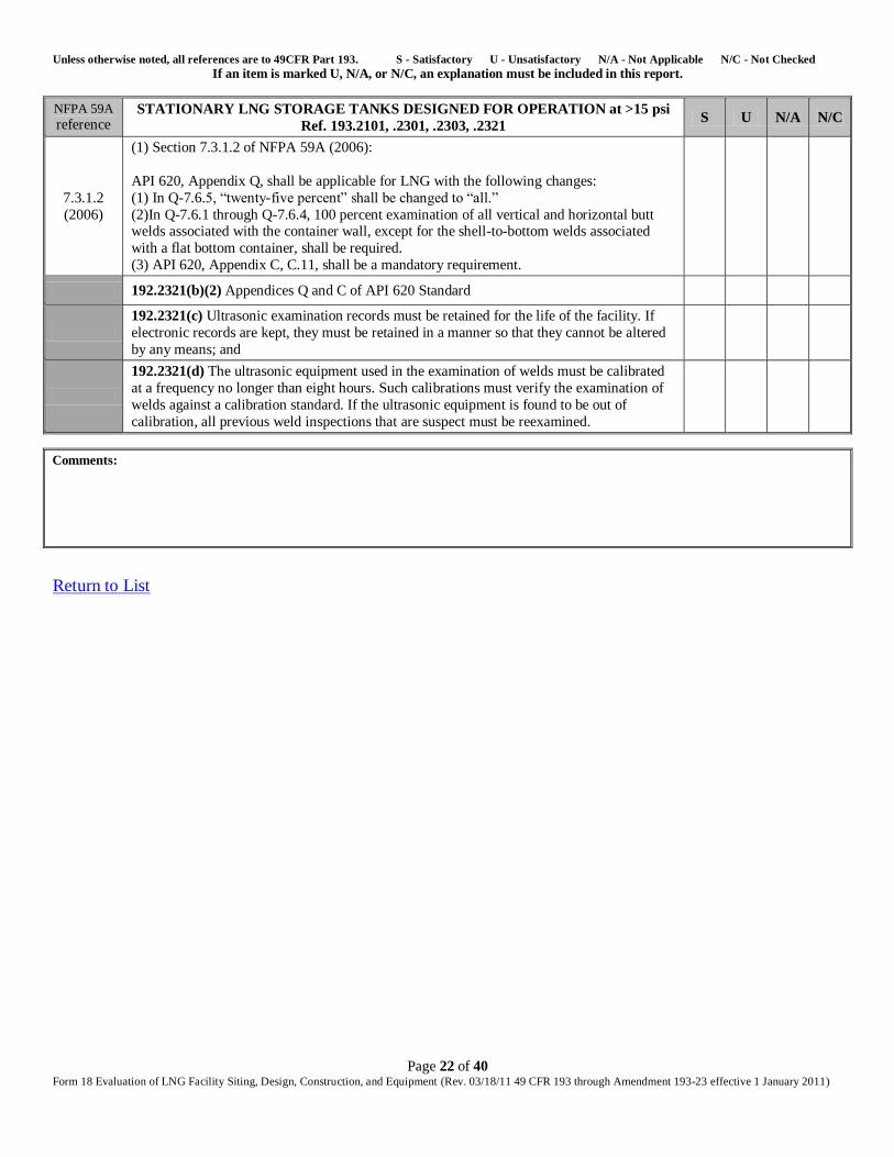
7.3.1.2
(2006)
(1) Section 7.3.1.2 of NFPA 59A (2006):
API 620, Appendix Q, shall be applicable for LNG with the following changes:
(1) In Q-7.6.5, ―twenty-five percent‖ shall be changed to ―all.‖
(2)In Q-7.6.1 through Q-7.6.4, 100 percent examination of all vertical and horizontal butt welds associated with the container wall, except for the shell-to-bottom welds associated
with a flat bottom container, shall be required.
(3) API 620, Appendix C, C.11, shall be a mandatory requirement.
192.2321(b)(2) Appendices Q and C of API 620 Standard
192.2321(c) Ultrasonic examination records must be retained for the life of the facility. If
electronic records are kept, they must be retained in a manner so that they cannot be altered
by any means; and
192.2321(d) The ultrasonic equipment used in the examination of welds must be calibrated
at a frequency no longer than eight hours. Such calibrations must verify the examination of
welds against a calibration standard. If the ultrasonic equipment is found to be out of
calibration, all previous weld inspections that are suspect must be reexamined.
Comments:
Return to List
Unless otherwise noted, all references are to 49CFR Part 193. S - Satisfactory U - Unsatisfactory N/A - Not Applicable N/C - Not Checked If an item is marked U, N/A, or N/C, an explanation must be included in this report.
Page 23 of 40 Form 18 Evaluation of LNG Facility Siting, Design, Construction, and Equipment (Rev. 03/18/11 49 CFR 193 through Amendment 193-23 effective 1 January 2011)
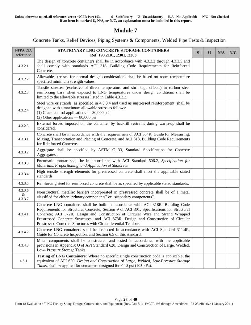
Module 7
Concrete Tanks, Relief Devices, Piping Systems & Components, Welded Pipe Tests & Inspection
NFPA 59A
reference STATIONARY LNG CONCRETE STORAGE CONTAINERS
Ref. 193.2101, .2301, .2303 S U N/A N/C
4.3.2.1
The design of concrete containers shall be in accordance with 4.3.2.2 through 4.3.2.5 and
shall comply with standards ACI 318, Building Code Requirements for Reinforced
Concrete.
4.3.2.2 Allowable stresses for normal design considerations shall be based on room temperature
specified minimum strength values.
4.3.2.3
Tensile stresses (exclusive of direct temperature and shrinkage effects) in carbon steel
reinforcing bars when exposed to LNG temperatures under design conditions shall be
limited to the allowable stresses listed in Table 4.3.2.3.
4.3.2.4
Steel wire or strands, as specified in 4.3.3.4 and used as unstressed reinforcement, shall be
designed with a maximum allowable stress as follows:
(1) Crack control applications — 30,000 psi
(2) Other applications — 80,000 psi
4.3.2.5 External forces imposed on the container by backfill restraint during warm-up shall be
considered.
4.3.3.1
Concrete shall be in accordance with the requirements of ACI 304R, Guide for Measuring,
Mixing, Transportation and Placing of Concrete, and ACI 318, Building Code Requirements
for Reinforced Concrete.
4.3.3.2 Aggregate shall be specified by ASTM C 33, Standard Specification for Concrete
Aggregates .
4.3.3.3 Pneumatic mortar shall be in accordance with ACI Standard 506.2, Specification for
Materials, Proportioning, and Application of Shotcrete.
4.3.3.4 High tensile strength elements for prestressed concrete shall meet the applicable stated standards.
4.3.3.5 Reinforcing steel for reinforced concrete shall be as specified by applicable stated standards.
4.3.3.6 &
4.3.3.7
Nonstructural metallic barriers incorporated in prestressed concrete shall be of a metal
classified for either ―primary components‖ or ―secondary components‖.
4.3.4.1
Concrete LNG containers shall be built in accordance with ACI 318R, Building Code
Requirements for Structural Concrete; Section 9 of ACI 301, Specifications for Structural
Concrete; ACI 372R, Design and Construction of Circular Wire and Strand Wrapped
Prestressed Concrete Structures; and ACI 373R, Design and Construction of Circular
Prestressed Concrete Structures with Circumferential Tendons.
4.3.4.2 Concrete LNG containers shall be inspected in accordance with ACI Standard 311.4R,
Guide for Concrete Inspection, and Section 6.5 of this standard.
4.3.4.3 Metal components shall be constructed and tested in accordance with the applicable
provisions in Appendix Q of API Standard 620, Design and Construction of Large, Welded,
Low- Pressure Storage Tanks.
4.5.1
Testing of LNG Containers: Where no specific single construction code is applicable, the
equivalent of API 620, Design and Construction of Large, Welded, Low-Pressure Storage
Tanks, shall be applied for containers designed for ≤ 15 psi (103 kPa).
Unless otherwise noted, all references are to 49CFR Part 193. S - Satisfactory U - Unsatisfactory N/A - Not Applicable N/C - Not Checked If an item is marked U, N/A, or N/C, an explanation must be included in this report.
Page 24 of 40 Form 18 Evaluation of LNG Facility Siting, Design, Construction, and Equipment (Rev. 03/18/11 49 CFR 193 through Amendment 193-23 effective 1 January 2011)
NFPA 59A
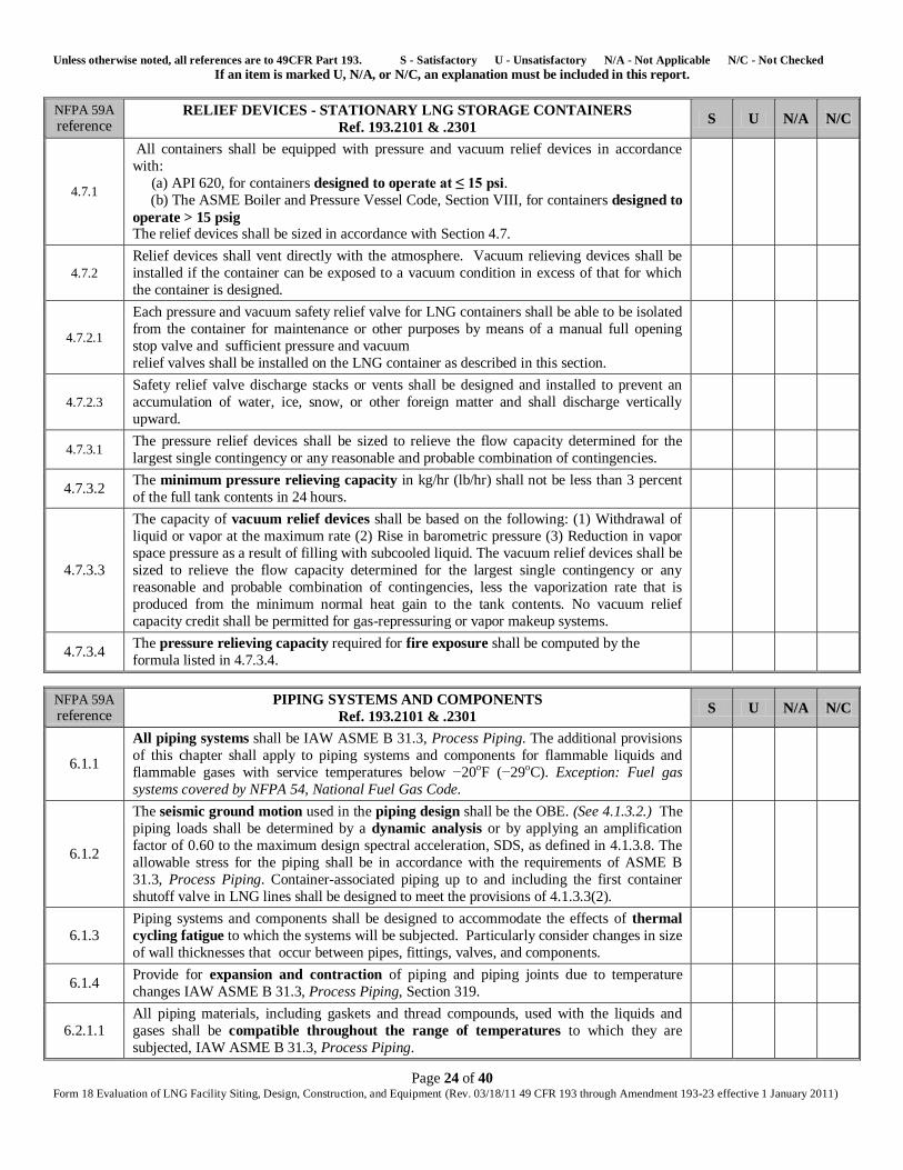
reference RELIEF DEVICES - STATIONARY LNG STORAGE CONTAINERS
Ref. 193.2101 & .2301 S U N/A N/C
4.7.1
All containers shall be equipped with pressure and vacuum relief devices in accordance
with:
(a) API 620, for containers designed to operate at ≤ 15 psi.
(b) The ASME Boiler and Pressure Vessel Code, Section VIII, for containers designed to
operate > 15 psig The relief devices shall be sized in accordance with Section 4.7.
4.7.2
Relief devices shall vent directly with the atmosphere. Vacuum relieving devices shall be
installed if the container can be exposed to a vacuum condition in excess of that for which
the container is designed.
4.7.2.1
Each pressure and vacuum safety relief valve for LNG containers shall be able to be isolated
from the container for maintenance or other purposes by means of a manual full opening
stop valve and sufficient pressure and vacuum
relief valves shall be installed on the LNG container as described in this section.
4.7.2.3
Safety relief valve discharge stacks or vents shall be designed and installed to prevent an
accumulation of water, ice, snow, or other foreign matter and shall discharge vertically
upward.
4.7.3.1 The pressure relief devices shall be sized to relieve the flow capacity determined for the
largest single contingency or any reasonable and probable combination of contingencies.
4.7.3.2 The minimum pressure relieving capacity in kg/hr (lb/hr) shall not be less than 3 percent
of the full tank contents in 24 hours.
4.7.3.3
The capacity of vacuum relief devices shall be based on the following: (1) Withdrawal of
liquid or vapor at the maximum rate (2) Rise in barometric pressure (3) Reduction in vapor
space pressure as a result of filling with subcooled liquid. The vacuum relief devices shall be
sized to relieve the flow capacity determined for the largest single contingency or any
reasonable and probable combination of contingencies, less the vaporization rate that is
produced from the minimum normal heat gain to the tank contents. No vacuum relief
capacity credit shall be permitted for gas-repressuring or vapor makeup systems.
4.7.3.4 The pressure relieving capacity required for fire exposure shall be computed by the
formula listed in 4.7.3.4.
NFPA 59A
reference PIPING SYSTEMS AND COMPONENTS
Ref. 193.2101 & .2301 S U N/A N/C
6.1.1
All piping systems shall be IAW ASME B 31.3, Process Piping. The additional provisions
of this chapter shall apply to piping systems and components for flammable liquids and
flammable gases with service temperatures below −20oF (−29oC). Exception: Fuel gas
systems covered by NFPA 54, National Fuel Gas Code.
6.1.2
The seismic ground motion used in the piping design shall be the OBE. (See 4.1.3.2.) The
piping loads shall be determined by a dynamic analysis or by applying an amplification
factor of 0.60 to the maximum design spectral acceleration, SDS, as defined in 4.1.3.8. The
allowable stress for the piping shall be in accordance with the requirements of ASME B
31.3, Process Piping. Container-associated piping up to and including the first container
shutoff valve in LNG lines shall be designed to meet the provisions of 4.1.3.3(2).
6.1.3
Piping systems and components shall be designed to accommodate the effects of thermal
cycling fatigue to which the systems will be subjected. Particularly consider changes in size
of wall thicknesses that occur between pipes, fittings, valves, and components.
6.1.4 Provide for expansion and contraction of piping and piping joints due to temperature
changes IAW ASME B 31.3, Process Piping, Section 319.
6.2.1.1
All piping materials, including gaskets and thread compounds, used with the liquids and
gases shall be compatible throughout the range of temperatures to which they are
subjected, IAW ASME B 31.3, Process Piping.
Unless otherwise noted, all references are to 49CFR Part 193. S - Satisfactory U - Unsatisfactory N/A - Not Applicable N/C - Not Checked If an item is marked U, N/A, or N/C, an explanation must be included in this report.
Page 25 of 40 Form 18 Evaluation of LNG Facility Siting, Design, Construction, and Equipment (Rev. 03/18/11 49 CFR 193 through Amendment 193-23 effective 1 January 2011)
NFPA 59A
reference PIPING SYSTEMS AND COMPONENTS
Ref. 193.2101 & .2301 S U N/A N/C
6.2.1.2
Piping that can be exposed to the cold of an LNG or refrigerant spill or the heat of an
ignited spill during an emergency where such exposure could result in a failure of the piping
that would significantly increase the emergency shall be IAW one of the following:
(1) Made of material(s) that can withstand both its normal operating temperature and the
extreme temperature to which it might be subjected during the emergency (2) Protected by insulation or other means to delay failure due to such extreme temperatures
until corrective action can be taken by the operator
(3) Capable of being isolated and having the flow stopped where piping is exposed only to
the heat of an ignited spill during the emergency.
6.2.4.1
In addition to complying with ASME B 31.3, Process Piping, Section 307, valves shall
comply with ASME B 31.5, Refrigeration Piping; ASME B 31.8, Gas Transmission and
Distribution Piping Systems; or API 6D, Specification for Pipeline Valves, if design
conditions fall within the scope of these standards.
6.3.2.4 Gasket material selection shall consider exposure to fire.
6.3.3.1
Extended bonnet valves shall be installed with packing seals in a position that prevents
leakage or malfunction due to freezing. If the extended bonnet in a cryogenic liquid line is
installed at an angle greater than 45 degrees from the upright vertical position, evidence of
satisfactory service in the installed position shall be demonstrated.
6.3.3.2
Shutoff valves are required on container, tank, and vessel connections.
Exception No. 1: Relief valve connections. [Shutoff valves shall be permitted only at
connections for relief valves IAW with the ASME Boiler and Pressure Vessel Code, Section
VIII, Division 1, UG-125(d), and Appendix M, M-5 and M-6.]
Exception No. 2: Connections for liquid level alarms shall be as required by 7.1.1.2.
Exception No. 3: Connections that are blind flanged or plugged. Shutoff valves shall be located as close as practical to such containers, tanks, and vessels and shall be located inside
the impounding area.
6.3.3.5 Valves and valve controls shall be designed to allow operation under icing conditions, if
such conditions can exist.
6.3.3.6
Emergency shutoff valves that would require excessive time to operate during an emergency
[or valves ≥ 8 in. (200 mm)] shall have powered operators and have a means for manual
operation.
6.3.4.1 Welder qualification and performance shall be IAW Section 328.2 of ASME B 31.3,
Process Piping, and 6.3.4.2 of NFPA-59A.
6.3.4.2
Use qualified welding procedures selected to minimize degradation of the low-temperature
properties of the pipe when welding impact-tested materials. Use procedures and
techniques to minimize the danger of burn-throughs when welding attachments to unusually
thin pipe.
6.6.1
Pressure tests (piping) shall be conducted in accordance with ASME B 31.3, Process
Piping, Section 345. To avoid possible brittle failure, carbon and low-alloy steel piping shall
be pressure tested at metal temperatures suitably above their nil ductility transition
temperature.
6.6.2
Records of pressure, test medium temperature, and ambient temperature shall be maintained
for the duration of each test. These records shall be maintained for the life of the facility or
until such time as a retest is conducted.
6.8.1
Pressure-relieving safety devices shall be arranged so that the possibility of damage to
piping or appurtenances is reduced to a minimum. The means for adjusting relief valve set
pressure shall be sealed.
6.8.2 A thermal expansion relief valve shall be installed as required to prevent overpressure in
any section of a liquid or cold vapor pipeline that can be isolated by valves.
Unless otherwise noted, all references are to 49CFR Part 193. S - Satisfactory U - Unsatisfactory N/A - Not Applicable N/C - Not Checked If an item is marked U, N/A, or N/C, an explanation must be included in this report.
Page 26 of 40 Form 18 Evaluation of LNG Facility Siting, Design, Construction, and Equipment (Rev. 03/18/11 49 CFR 193 through Amendment 193-23 effective 1 January 2011)
NFPA 59A
reference PIPING SYSTEMS AND COMPONENTS
Ref. 193.2101 & .2301 S U N/A N/C
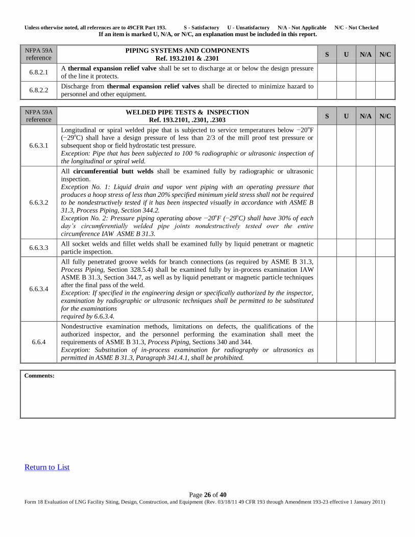
6.8.2.1 A thermal expansion relief valve shall be set to discharge at or below the design pressure
of the line it protects.
6.8.2.2 Discharge from thermal expansion relief valves shall be directed to minimize hazard to
personnel and other equipment.
NFPA 59A
reference WELDED PIPE TESTS & INSPECTION
Ref. 193.2101, .2301, .2303 S U N/A N/C
6.6.3.1
Longitudinal or spiral welded pipe that is subjected to service temperatures below −20oF (−29oC) shall have a design pressure of less than 2/3 of the mill proof test pressure or
subsequent shop or field hydrostatic test pressure.
Exception: Pipe that has been subjected to 100 % radiographic or ultrasonic inspection of
the longitudinal or spiral weld.
6.6.3.2
All circumferential butt welds shall be examined fully by radiographic or ultrasonic
inspection.
Exception No. 1: Liquid drain and vapor vent piping with an operating pressure that
produces a hoop stress of less than 20% specified minimum yield stress shall not be required
to be nondestructively tested if it has been inspected visually in accordance with ASME B
31.3, Process Piping, Section 344.2.
Exception No. 2: Pressure piping operating above −20oF (−29oC) shall have 30% of each
day’s circumferentially welded pipe joints nondestructively tested over the entire
circumference IAW ASME B 31.3.
6.6.3.3 All socket welds and fillet welds shall be examined fully by liquid penetrant or magnetic
particle inspection.
6.6.3.4
All fully penetrated groove welds for branch connections (as required by ASME B 31.3,
Process Piping, Section 328.5.4) shall be examined fully by in-process examination IAW
ASME B 31.3, Section 344.7, as well as by liquid penetrant or magnetic particle techniques after the final pass of the weld.
Exception: If specified in the engineering design or specifically authorized by the inspector,
examination by radiographic or ultrasonic techniques shall be permitted to be substituted
for the examinations
required by 6.6.3.4.
6.6.4
Nondestructive examination methods, limitations on defects, the qualifications of the
authorized inspector, and the personnel performing the examination shall meet the
requirements of ASME B 31.3, Process Piping, Sections 340 and 344.
Exception: Substitution of in-process examination for radiography or ultrasonics as
permitted in ASME B 31.3, Paragraph 341.4.1, shall be prohibited.
Comments:
Return to List
Unless otherwise noted, all references are to 49CFR Part 193. S - Satisfactory U - Unsatisfactory N/A - Not Applicable N/C - Not Checked If an item is marked U, N/A, or N/C, an explanation must be included in this report.
Page 27 of 40 Form 18 Evaluation of LNG Facility Siting, Design, Construction, and Equipment (Rev. 03/18/11 49 CFR 193 through Amendment 193-23 effective 1 January 2011)
Module 8
Corrosion Control (NFPA 59A & 193.2304)
NFPA 59A
reference CORROSION CONTROL
Ref. 193.2101, .2301, .2629 S U N/A N/C
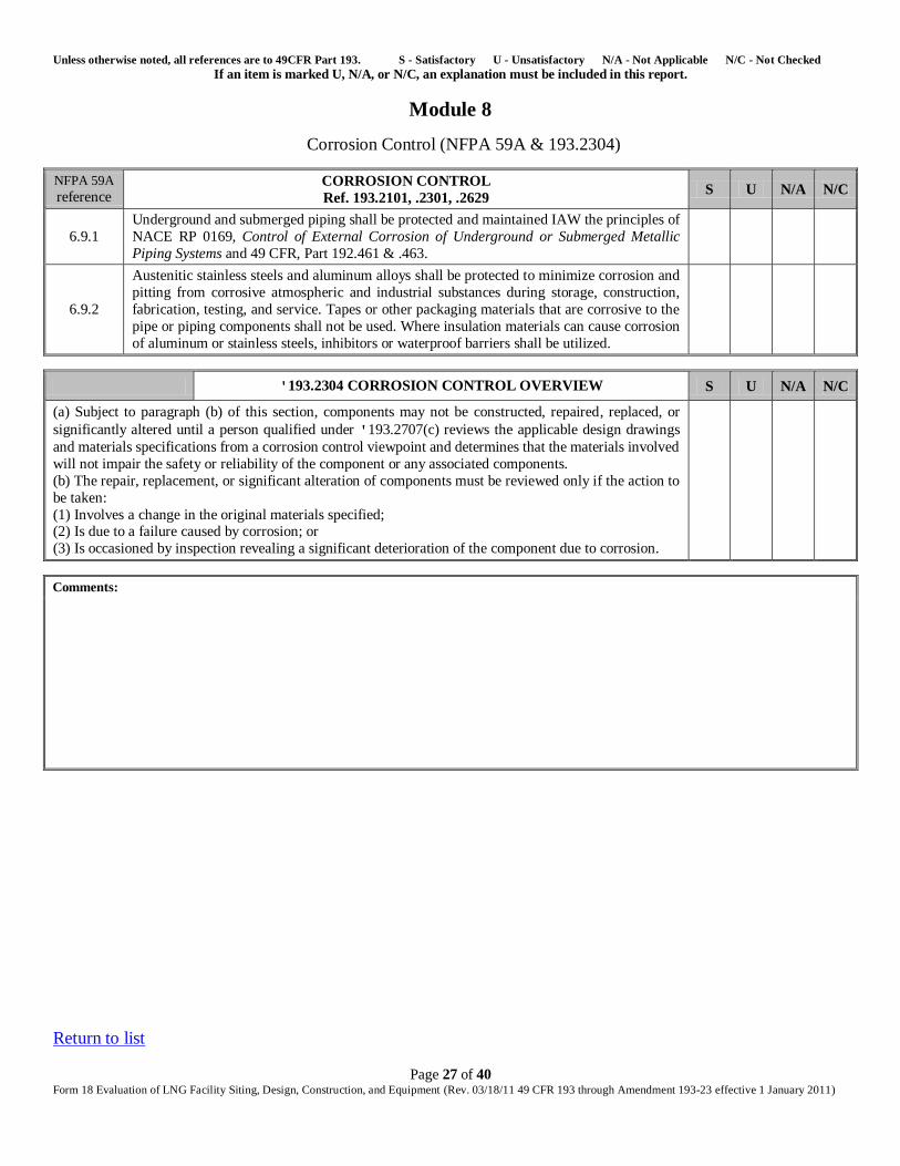
6.9.1
Underground and submerged piping shall be protected and maintained IAW the principles of
NACE RP 0169, Control of External Corrosion of Underground or Submerged Metallic
Piping Systems and 49 CFR, Part 192.461 & .463.
6.9.2
Austenitic stainless steels and aluminum alloys shall be protected to minimize corrosion and
pitting from corrosive atmospheric and industrial substances during storage, construction,
fabrication, testing, and service. Tapes or other packaging materials that are corrosive to the
pipe or piping components shall not be used. Where insulation materials can cause corrosion
of aluminum or stainless steels, inhibitors or waterproof barriers shall be utilized.
'193.2304 CORROSION CONTROL OVERVIEW S U N/A N/C
(a) Subject to paragraph (b) of this section, components may not be constructed, repaired, replaced, or
significantly altered until a person qualified under '193.2707(c) reviews the applicable design drawings
and materials specifications from a corrosion control viewpoint and determines that the materials involved
will not impair the safety or reliability of the component or any associated components.
(b) The repair, replacement, or significant alteration of components must be reviewed only if the action to
be taken:
(1) Involves a change in the original materials specified; (2) Is due to a failure caused by corrosion; or
(3) Is occasioned by inspection revealing a significant deterioration of the component due to corrosion.
Comments:
Return to list
Unless otherwise noted, all references are to 49CFR Part 193. S - Satisfactory U - Unsatisfactory N/A - Not Applicable N/C - Not Checked If an item is marked U, N/A, or N/C, an explanation must be included in this report.
Page 28 of 40 Form 18 Evaluation of LNG Facility Siting, Design, Construction, and Equipment (Rev. 03/18/11 49 CFR 193 through Amendment 193-23 effective 1 January 2011)
Module 9
LNG Level Gauging, Refrigerant & Process Fluids, Pressure & Vacuum Gauges, Temperature Monitoring
NFPA 59A
reference LNG LEVEL GAUGING – LNG CONTAINERS
Ref. 193.2301 S U N/A N/C
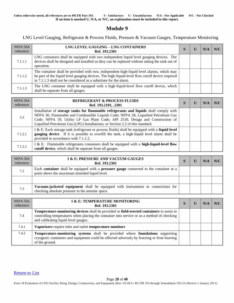
7.1.1.1
LNG containers shall be equipped with two independent liquid level gauging devices. The
devices shall be designed and installed so they can be replaced without taking the tank out of
operation.
7.1.1.2
The container shall be provided with two, independent high-liquid level alarms, which may
be part of the liquid level gauging devices. The high-liquid-level flow cutoff device required
in 7.1.1.3 shall not be considered as a substitute for the alarm.
7.1.1.3 The LNG container shall be equipped with a high-liquid-level flow cutoff device, which
shall be separate from all gauges.
NFPA 59A
reference REFRIGERANT & PROCESS FLUIDS
Ref. 193.2101, .2301 S U N/A N/C
3.3
Installation of storage tanks for flammable refrigerants and liquids shall comply with
NFPA 30, Flammable and Combustible Liquids Code; NFPA 58, Liquefied Petroleum Gas Code; NFPA 59, Utility LP Gas Plant Code; API 2510, Design and Construction of
Liquefied Petroleum Gas (LPG) Installations; or Section 2.2 of this standard.
7.1.2.1
I & E: Each storage tank (refrigerant or process fluids) shall be equipped with a liquid level
gauging device. If it is possible to overfill the tank, a high-liquid level alarm shall be
provided in accordance with 7.1.1.2.
7.1.2.2 I & E: Flammable refrigerants containers shall be equipped with a high-liquid-level flow
cutoff device, which shall be separate from all gauges.
NFPA 59A
reference I & E: PRESSURE AND VACUUM GAUGES
Ref. 193.2301 S U N/A N/C
7.2 Each container shall be equipped with a pressure gauge connected to the container at a
point above the maximum intended liquid level.
7.3 Vacuum-jacketed equipment shall be equipped with instruments or connections for
checking absolute pressure in the annular space.
NFPA 59A
reference I & E: TEMPERATURE MONITORING
Ref. 193.2301 S U N/A N/C
7.4
Temperature-monitoring devices shall be provided in field-erected containers to assist in
controlling temperatures when placing the container into service or as a method of checking
and calibrating liquid level gauges.
7.4.1 Vaporizers require inlet and outlet temperature monitors
7.4.2 Temperature-monitoring systems shall be provided where foundations supporting
cryogenic containers and equipment could be affected adversely by freezing or frost heaving
of the ground.
Return to List
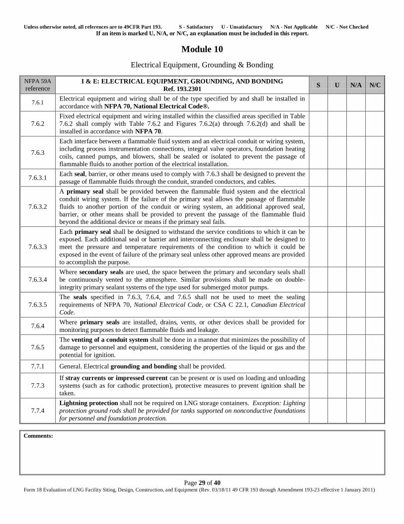
Unless otherwise noted, all references are to 49CFR Part 193. S - Satisfactory U - Unsatisfactory N/A - Not Applicable N/C - Not Checked If an item is marked U, N/A, or N/C, an explanation must be included in this report.
Page 29 of 40 Form 18 Evaluation of LNG Facility Siting, Design, Construction, and Equipment (Rev. 03/18/11 49 CFR 193 through Amendment 193-23 effective 1 January 2011)
Module 10
Electrical Equipment, Grounding & Bonding
NFPA 59A
reference I & E: ELECTRICAL EQUIPMENT, GROUNDING, AND BONDING
Ref. 193.2301 S U N/A N/C
7.6.1 Electrical equipment and wiring shall be of the type specified by and shall be installed in
accordance with NFPA 70, National Electrical Code®.
7.6.2
Fixed electrical equipment and wiring installed within the classified areas specified in Table
7.6.2 shall comply with Table 7.6.2 and Figures 7.6.2(a) through 7.6.2(d) and shall be
installed in accordance with NFPA 70.
7.6.3
Each interface between a flammable fluid system and an electrical conduit or wiring system,
including process instrumentation connections, integral valve operators, foundation heating
coils, canned pumps, and blowers, shall be sealed or isolated to prevent the passage of
flammable fluids to another portion of the electrical installation.
7.6.3.1 Each seal, barrier, or other means used to comply with 7.6.3 shall be designed to prevent the
passage of flammable fluids through the conduit, stranded conductors, and cables.
7.6.3.2
A primary seal shall be provided between the flammable fluid system and the electrical
conduit wiring system. If the failure of the primary seal allows the passage of flammable
fluids to another portion of the conduit or wiring system, an additional approved seal,
barrier, or other means shall be provided to prevent the passage of the flammable fluid beyond the additional device or means if the primary seal fails.
7.6.3.3
Each primary seal shall be designed to withstand the service conditions to which it can be exposed. Each additional seal or barrier and interconnecting enclosure shall be designed to
meet the pressure and temperature requirements of the condition to which it could be
exposed in the event of failure of the primary seal unless other approved means are provided
to accomplish the purpose.
7.6.3.4
Where secondary seals are used, the space between the primary and secondary seals shall
be continuously vented to the atmosphere. Similar provisions shall be made on double-
integrity primary sealant systems of the type used for submerged motor pumps.
7.6.3.5
The seals specified in 7.6.3, 7.6.4, and 7.6.5 shall not be used to meet the sealing
requirements of NFPA 70, National Electrical Code, or CSA C 22.1, Canadian Electrical
Code.
7.6.4 Where primary seals are installed, drains, vents, or other devices shall be provided for
monitoring purposes to detect flammable fluids and leakage.
7.6.5
The venting of a conduit system shall be done in a manner that minimizes the possibility of
damage to personnel and equipment, considering the properties of the liquid or gas and the
potential for ignition.
7.7.1 General. Electrical grounding and bonding shall be provided.
7.7.3
If stray currents or impressed current can be present or is used on loading and unloading
systems (such as for cathodic protection), protective measures to prevent ignition shall be
taken.
7.7.4
Lightning protection shall not be required on LNG storage containers. Exception: Lighting
protection ground rods shall be provided for tanks supported on nonconductive foundations
for personnel and foundation protection.
Comments:
Unless otherwise noted, all references are to 49CFR Part 193. S - Satisfactory U - Unsatisfactory N/A - Not Applicable N/C - Not Checked If an item is marked U, N/A, or N/C, an explanation must be included in this report.
Page 30 of 40 Form 18 Evaluation of LNG Facility Siting, Design, Construction, and Equipment (Rev. 03/18/11 49 CFR 193 through Amendment 193-23 effective 1 January 2011)
Return to List
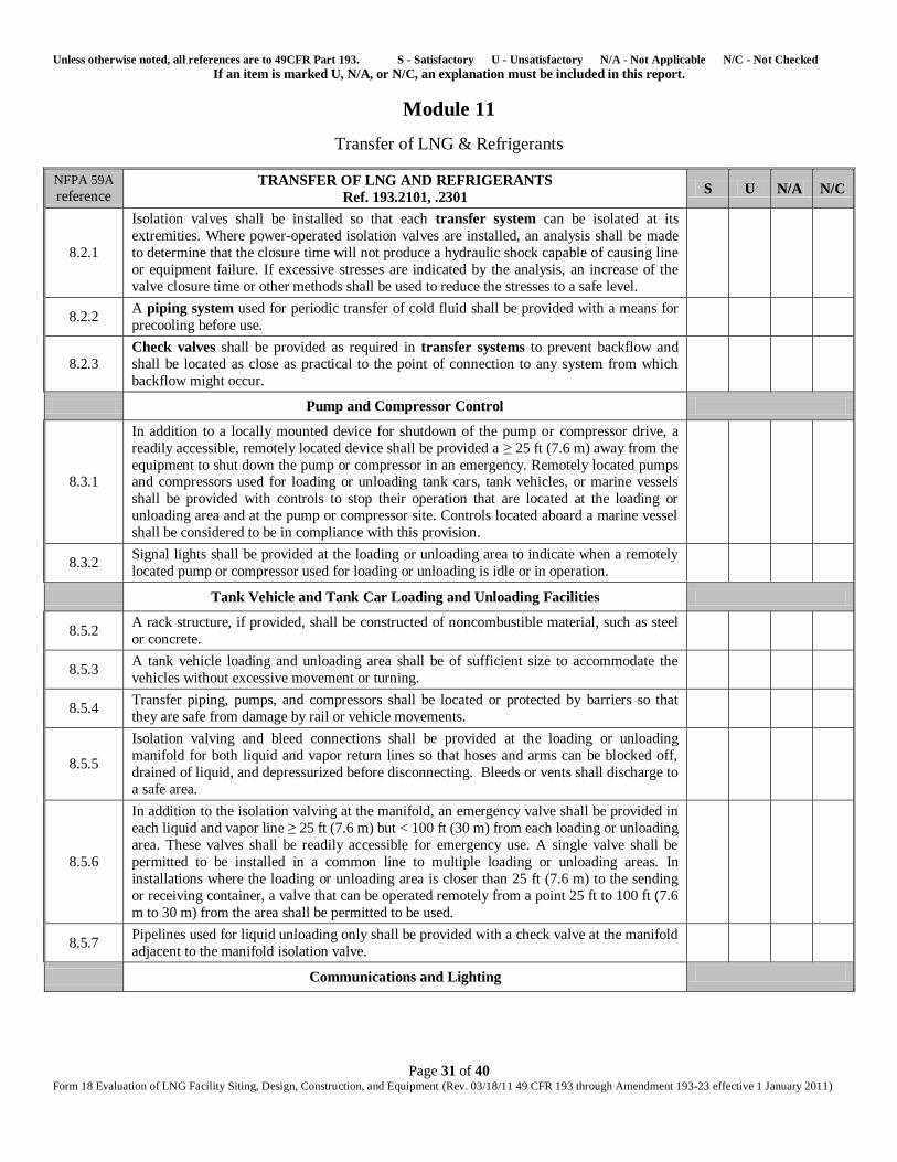
Unless otherwise noted, all references are to 49CFR Part 193. S - Satisfactory U - Unsatisfactory N/A - Not Applicable N/C - Not Checked If an item is marked U, N/A, or N/C, an explanation must be included in this report.
Page 31 of 40 Form 18 Evaluation of LNG Facility Siting, Design, Construction, and Equipment (Rev. 03/18/11 49 CFR 193 through Amendment 193-23 effective 1 January 2011)
Module 11
Transfer of LNG & Refrigerants
NFPA 59A
reference TRANSFER OF LNG AND REFRIGERANTS
Ref. 193.2101, .2301 S U N/A N/C
8.2.1
Isolation valves shall be installed so that each transfer system can be isolated at its
extremities. Where power-operated isolation valves are installed, an analysis shall be made
to determine that the closure time will not produce a hydraulic shock capable of causing line
or equipment failure. If excessive stresses are indicated by the analysis, an increase of the
valve closure time or other methods shall be used to reduce the stresses to a safe level.
8.2.2 A piping system used for periodic transfer of cold fluid shall be provided with a means for
precooling before use.
8.2.3
Check valves shall be provided as required in transfer systems to prevent backflow and
shall be located as close as practical to the point of connection to any system from which
backflow might occur.
Pump and Compressor Control
8.3.1
In addition to a locally mounted device for shutdown of the pump or compressor drive, a
readily accessible, remotely located device shall be provided a ≥ 25 ft (7.6 m) away from the
equipment to shut down the pump or compressor in an emergency. Remotely located pumps and compressors used for loading or unloading tank cars, tank vehicles, or marine vessels
shall be provided with controls to stop their operation that are located at the loading or
unloading area and at the pump or compressor site. Controls located aboard a marine vessel
shall be considered to be in compliance with this provision.
8.3.2 Signal lights shall be provided at the loading or unloading area to indicate when a remotely
located pump or compressor used for loading or unloading is idle or in operation.
Tank Vehicle and Tank Car Loading and Unloading Facilities
8.5.2 A rack structure, if provided, shall be constructed of noncombustible material, such as steel
or concrete.
8.5.3 A tank vehicle loading and unloading area shall be of sufficient size to accommodate the
vehicles without excessive movement or turning.
8.5.4 Transfer piping, pumps, and compressors shall be located or protected by barriers so that
they are safe from damage by rail or vehicle movements.
8.5.5
Isolation valving and bleed connections shall be provided at the loading or unloading
manifold for both liquid and vapor return lines so that hoses and arms can be blocked off,
drained of liquid, and depressurized before disconnecting. Bleeds or vents shall discharge to
a safe area.
8.5.6
In addition to the isolation valving at the manifold, an emergency valve shall be provided in
each liquid and vapor line ≥ 25 ft (7.6 m) but < 100 ft (30 m) from each loading or unloading
area. These valves shall be readily accessible for emergency use. A single valve shall be
permitted to be installed in a common line to multiple loading or unloading areas. In
installations where the loading or unloading area is closer than 25 ft (7.6 m) to the sending
or receiving container, a valve that can be operated remotely from a point 25 ft to 100 ft (7.6
m to 30 m) from the area shall be permitted to be used.
8.5.7 Pipelines used for liquid unloading only shall be provided with a check valve at the manifold
adjacent to the manifold isolation valve.
Communications and Lighting
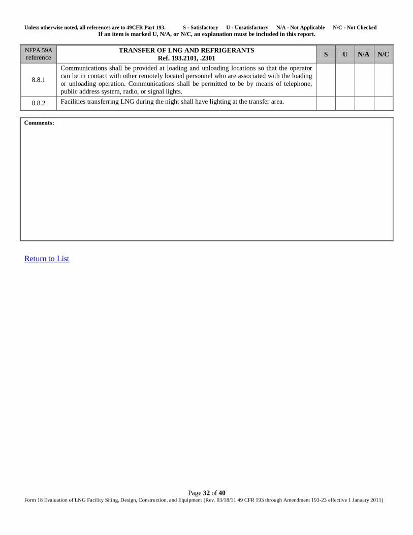
Unless otherwise noted, all references are to 49CFR Part 193. S - Satisfactory U - Unsatisfactory N/A - Not Applicable N/C - Not Checked If an item is marked U, N/A, or N/C, an explanation must be included in this report.
Page 32 of 40 Form 18 Evaluation of LNG Facility Siting, Design, Construction, and Equipment (Rev. 03/18/11 49 CFR 193 through Amendment 193-23 effective 1 January 2011)
NFPA 59A
reference TRANSFER OF LNG AND REFRIGERANTS
Ref. 193.2101, .2301 S U N/A N/C
8.8.1
Communications shall be provided at loading and unloading locations so that the operator
can be in contact with other remotely located personnel who are associated with the loading
or unloading operation. Communications shall be permitted to be by means of telephone,
public address system, radio, or signal lights.
8.8.2 Facilities transferring LNG during the night shall have lighting at the transfer area.
Comments:
Return to List
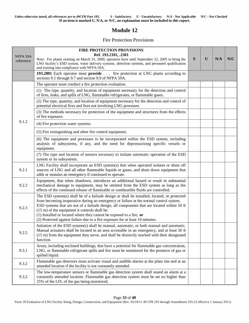
Unless otherwise noted, all references are to 49CFR Part 193. S - Satisfactory U - Unsatisfactory N/A - Not Applicable N/C - Not Checked If an item is marked U, N/A, or N/C, an explanation must be included in this report.
Page 33 of 40 Form 18 Evaluation of LNG Facility Siting, Design, Construction, and Equipment (Rev. 03/18/11 49 CFR 193 through Amendment 193-23 effective 1 January 2011)
Module 12
Fire Protection Provisions
NFPA 59A
reference
FIRE PROTECTION PROVISIONS
Ref. 193.2101, .2301 Note: For plants existing on March 31, 2000, operators have until September 12, 2005 to bring the LNG facility’s ESD system, water delivery systems, detection systems, and personnel qualification and training into compliance with NFPA-59A.
S U N/A N/C
193.2801 Each operator must provide . . . fire protection at LNG plants according to
sections 9.1 through 9.7 and section 9.9 of NFPA 59A.
9.1.2
The operator must conduct a fire protection evaluation.
(1) The type, quantity, and location of equipment necessary for the detection and control of fires, leaks, and spills of LNG, flammable refrigerants, or flammable gases.
(2) The type, quantity, and location of equipment necessary for the detection and control of potential electrical fires and fires not involving LNG processes.
(3) The methods necessary for protection of the equipment and structures from the effects of fire exposure.
(4) Fire protection water systems.
(5) Fire extinguishing and other fire control equipment.
(6) The equipment and processes to be incorporated within the ESD system, including
analysis of subsystems, if any, and the need for depressurizing specific vessels or
equipment.
(7) The type and location of sensors necessary to initiate automatic operation of the ESD
system or its subsystems.
9.2.1
LNG Facility shall incorporate an ESD system(s) that when operated isolates or shuts off
sources of LNG and all other flammable liquids or gases, and shuts down equipment that adds or sustains an emergency if continued to operate.
9.2.2 Equipment, that when shutdown, introduces an additional hazard or result in substantial mechanical damage to equipment, may be omitted from the ESD system as long as the
effects of the continued release of flammable or combustible fluids are controlled.
9.2.3
The ESD system(s) shall be of a failsafe design or shall be installed, located, or protected
from becoming inoperative during an emergency or failure at the normal control system.
ESD systems that are not of a failsafe design, all components that are located within 50 ft
(15 m) of the equipment it controls shall be:
(1) Installed or located where they cannot be exposed to a fire, or
(2) Protected against failure due to a fire exposure for at least 10 minutes.
9.2.5
Initiation of the ESD system(s) shall be manual, automatic, or both manual and automatic.
Manual actuators shall be located in an area accessible in an emergency, and at least 50 ft
(15 m) from the equipment they serve, and shall be distinctly marked with their designated
function.
9.3.1
Areas, including enclosed buildings, that have a potential for flammable gas concentration,
LNG, or flammable refrigerant spills and fire must be monitored for the presence of gas or
spilled liquid.
9.3.2 Flammable gas detectors must activate visual and audible alarms at the plant site and at an
attended location if the facility is not constantly attended.
9.3.2
The low-temperature sensors or flammable gas detection system shall sound an alarm at a
constantly attended location. Flammable gas detection system must be set no higher than
25% of the LFL of the gas being monitored.

Unless otherwise noted, all references are to 49CFR Part 193. S - Satisfactory U - Unsatisfactory N/A - Not Applicable N/C - Not Checked If an item is marked U, N/A, or N/C, an explanation must be included in this report.
Page 34 of 40 Form 18 Evaluation of LNG Facility Siting, Design, Construction, and Equipment (Rev. 03/18/11 49 CFR 193 through Amendment 193-23 effective 1 January 2011)
NFPA 59A
reference
FIRE PROTECTION PROVISIONS
Ref. 193.2101, .2301 Note: For plants existing on March 31, 2000, operators have until September 12, 2005 to bring the LNG facility’s ESD system, water delivery systems, detection systems, and personnel qualification and training into compliance with NFPA-59A.
S U N/A N/C
9.3.3
Fire detectors must sound an alarm at the plant site and at an attended location if the
facility is not constantly attended. If so determined IAW 9.1.2 fire detectors shall activate
portions of the ESD system.
9.3.4 The detection systems required of the fire protection evaluation ( 9.1.2) shall be designed
and installed IAW NFPA-72 or NFPA-1221.
9.4.1 A fire water supply and delivery system must be provided, unless the fire protection
evaluation (9-1.2) indicates that fire water is unnecessary or impractical.
9.4.2
The fire water supply and distribution systems shall provide for the simultaneous supply of
fixed fire protection systems, at their design flow and pressure, plus 1000 gpm (63 L/sec)
for not less than 2 hours.
9.5.1 Portable or wheeled fire extinguishers, recommended for gas fires, available at strategic
locations.
Comments:
Return to List
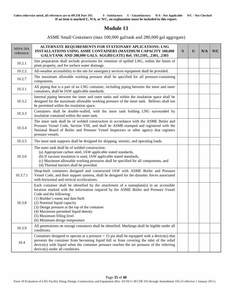
Unless otherwise noted, all references are to 49CFR Part 193. S - Satisfactory U - Unsatisfactory N/A - Not Applicable N/C - Not Checked If an item is marked U, N/A, or N/C, an explanation must be included in this report.
Page 35 of 40 Form 18 Evaluation of LNG Facility Siting, Design, Construction, and Equipment (Rev. 03/18/11 49 CFR 193 through Amendment 193-23 effective 1 January 2011)
Module 13
ASME Small Containers (max 100,000 gal/tank and 280,000 gal aggregate)
NFPA 59A
reference
ALTERNATE REQUIREMENTS FOR STATIONARY APLICATIONS: LNG
INSTALLATIONS USING ASME CONTAINERS (MAXIMUM CAPACITY 100,000
GALS/TANK AND 280,000 GALS. AGGREGATE) Ref. 193.2101, .2301, .2303
S U N/A N/C
10.2.1 Site preparation shall include provisions for retention of spilled LNG, within the limits of
plant property, and for surface water drainage.
10.2.2 All-weather accessibility to the site for emergency services equipment shall be provided.
10.2.7 The maximum allowable working pressure shall be specified for all pressure-containing
components.
10.3.1 All piping that is a part of an LNG container, including piping between the inner and outer
containers, shall be IAW applicable standards.
10.3.2
Internal piping between the inner and outer tanks and within the insulation space shall be
designed for the maximum allowable working pressure of the inner tank. Bellows shall not
be permitted within the insulation space.
10.3.3 Containers shall be double-walled, with the inner tank holding LNG surrounded by
insulation contained within the outer tank.
10.3.4
The inner tank shall be of welded construction in accordance with the ASME Boiler and
Pressure Vessel Code, Section VIII, and shall be ASME-stamped and registered with the
National Board of Boiler and Pressure Vessel Inspectors or other agency that registers
pressure vessels.
10.3.5 The inner tank supports shall be designed for shipping, seismic, and operating loads.
10.3.6
The outer tank shall be of welded construction:
(a) Appropriate carbon steel, IAW applicable stated standards,
(b) If vacuum insulation is used, IAW applicable stated standards,
(c) Maximum allowable working pressures shall be specified for all components, and
(d) Thermal barriers shall be provided.
10.3.7.1
Shop-built containers designed and constructed IAW with ASME Boiler and Pressure
Vessel Code, and their support systems, shall be designed for the dynamic forces associated
with horizontal and vertical accelerations.
10.3.8
Each container shall be identified by the attachment of a nameplate(s) in an accessible
location marked with the information required by the ASME Boiler and Pressure Vessel
Code and the following:
(1) Builder’s name and date built
(2) Nominal liquid capacity
(3) Design pressure at the top of the container (4) Maximum permitted liquid density
(5) Maximum filling level
(6) Minimum design temperature
10.3.9 All penetrations on storage containers shall be identified. Markings shall be legible under all
conditions.
10.4
Containers designed to operate at a pressure > 15 psi shall be equipped with a device(s) that
prevents the container from becoming liquid full or from covering the inlet of the relief
device(s) with liquid when the container pressure reaches the set pressure of the relieving
device(s) under all conditions.
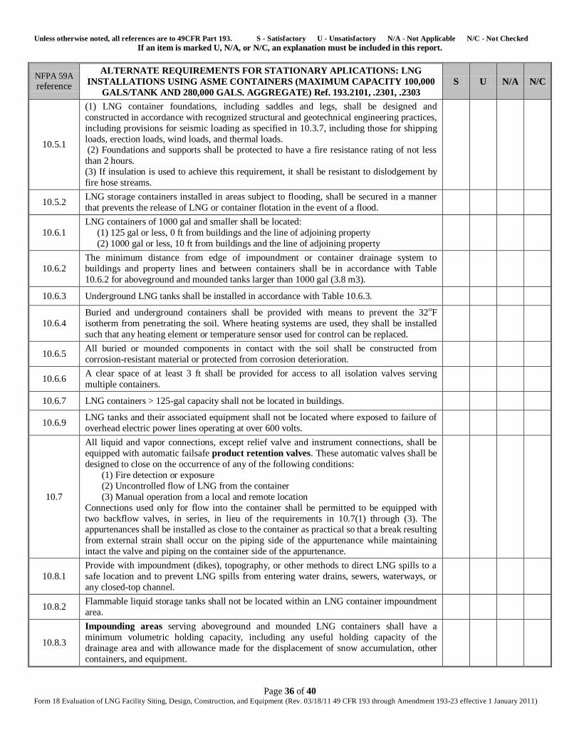
Unless otherwise noted, all references are to 49CFR Part 193. S - Satisfactory U - Unsatisfactory N/A - Not Applicable N/C - Not Checked If an item is marked U, N/A, or N/C, an explanation must be included in this report.
Page 36 of 40 Form 18 Evaluation of LNG Facility Siting, Design, Construction, and Equipment (Rev. 03/18/11 49 CFR 193 through Amendment 193-23 effective 1 January 2011)
NFPA 59A
reference
ALTERNATE REQUIREMENTS FOR STATIONARY APLICATIONS: LNG
INSTALLATIONS USING ASME CONTAINERS (MAXIMUM CAPACITY 100,000
GALS/TANK AND 280,000 GALS. AGGREGATE) Ref. 193.2101, .2301, .2303
S U N/A N/C
10.5.1
(1) LNG container foundations, including saddles and legs, shall be designed and
constructed in accordance with recognized structural and geotechnical engineering practices,
including provisions for seismic loading as specified in 10.3.7, including those for shipping
loads, erection loads, wind loads, and thermal loads. (2) Foundations and supports shall be protected to have a fire resistance rating of not less
than 2 hours.
(3) If insulation is used to achieve this requirement, it shall be resistant to dislodgement by
fire hose streams.
10.5.2 LNG storage containers installed in areas subject to flooding, shall be secured in a manner
that prevents the release of LNG or container flotation in the event of a flood.
10.6.1
LNG containers of 1000 gal and smaller shall be located:
(1) 125 gal or less, 0 ft from buildings and the line of adjoining property
(2) 1000 gal or less, 10 ft from buildings and the line of adjoining property
10.6.2
The minimum distance from edge of impoundment or container drainage system to
buildings and property lines and between containers shall be in accordance with Table
10.6.2 for aboveground and mounded tanks larger than 1000 gal (3.8 m3).
10.6.3 Underground LNG tanks shall be installed in accordance with Table 10.6.3.
10.6.4
Buried and underground containers shall be provided with means to prevent the 32oF
isotherm from penetrating the soil. Where heating systems are used, they shall be installed
such that any heating element or temperature sensor used for control can be replaced.
10.6.5 All buried or mounded components in contact with the soil shall be constructed from
corrosion-resistant material or protected from corrosion deterioration.
10.6.6 A clear space of at least 3 ft shall be provided for access to all isolation valves serving
multiple containers.
10.6.7 LNG containers > 125-gal capacity shall not be located in buildings.
10.6.9 LNG tanks and their associated equipment shall not be located where exposed to failure of
overhead electric power lines operating at over 600 volts.
10.7
All liquid and vapor connections, except relief valve and instrument connections, shall be
equipped with automatic failsafe product retention valves. These automatic valves shall be
designed to close on the occurrence of any of the following conditions:
(1) Fire detection or exposure
(2) Uncontrolled flow of LNG from the container
(3) Manual operation from a local and remote location
Connections used only for flow into the container shall be permitted to be equipped with
two backflow valves, in series, in lieu of the requirements in 10.7(1) through (3). The appurtenances shall be installed as close to the container as practical so that a break resulting
from external strain shall occur on the piping side of the appurtenance while maintaining
intact the valve and piping on the container side of the appurtenance.
10.8.1
Provide with impoundment (dikes), topography, or other methods to direct LNG spills to a
safe location and to prevent LNG spills from entering water drains, sewers, waterways, or
any closed-top channel.
10.8.2 Flammable liquid storage tanks shall not be located within an LNG container impoundment
area.
10.8.3
Impounding areas serving aboveground and mounded LNG containers shall have a
minimum volumetric holding capacity, including any useful holding capacity of the
drainage area and with allowance made for the displacement of snow accumulation, other
containers, and equipment.
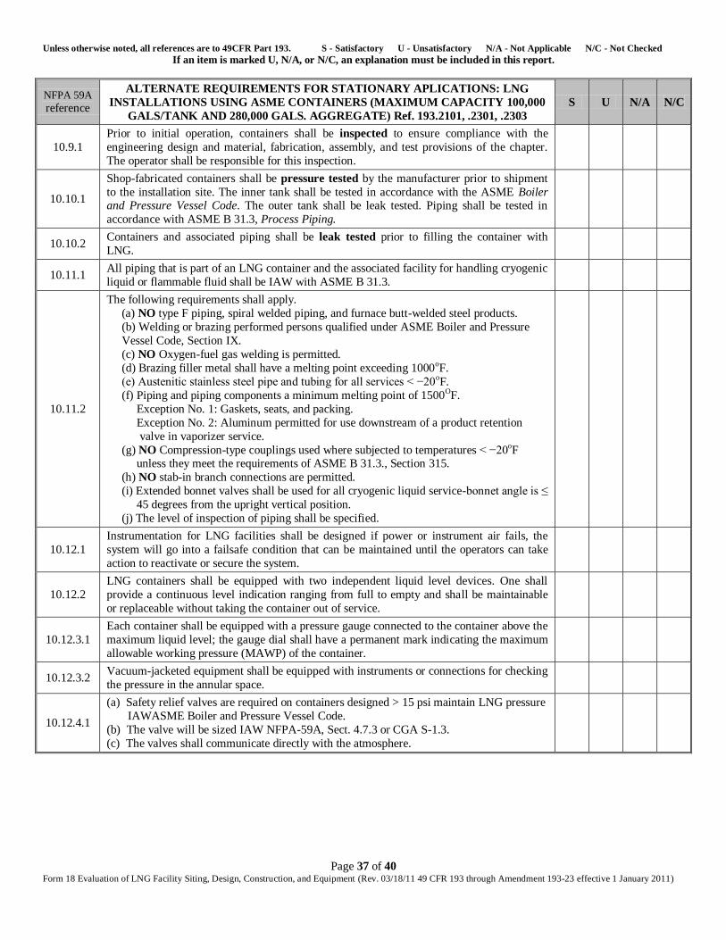
Unless otherwise noted, all references are to 49CFR Part 193. S - Satisfactory U - Unsatisfactory N/A - Not Applicable N/C - Not Checked If an item is marked U, N/A, or N/C, an explanation must be included in this report.
Page 37 of 40 Form 18 Evaluation of LNG Facility Siting, Design, Construction, and Equipment (Rev. 03/18/11 49 CFR 193 through Amendment 193-23 effective 1 January 2011)
NFPA 59A
reference
ALTERNATE REQUIREMENTS FOR STATIONARY APLICATIONS: LNG
INSTALLATIONS USING ASME CONTAINERS (MAXIMUM CAPACITY 100,000
GALS/TANK AND 280,000 GALS. AGGREGATE) Ref. 193.2101, .2301, .2303
S U N/A N/C
10.9.1
Prior to initial operation, containers shall be inspected to ensure compliance with the
engineering design and material, fabrication, assembly, and test provisions of the chapter.
The operator shall be responsible for this inspection.
10.10.1
Shop-fabricated containers shall be pressure tested by the manufacturer prior to shipment
to the installation site. The inner tank shall be tested in accordance with the ASME Boiler and Pressure Vessel Code. The outer tank shall be leak tested. Piping shall be tested in
accordance with ASME B 31.3, Process Piping.
10.10.2 Containers and associated piping shall be leak tested prior to filling the container with
LNG.
10.11.1 All piping that is part of an LNG container and the associated facility for handling cryogenic
liquid or flammable fluid shall be IAW with ASME B 31.3.
10.11.2
The following requirements shall apply.
(a) NO type F piping, spiral welded piping, and furnace butt-welded steel products.
(b) Welding or brazing performed persons qualified under ASME Boiler and Pressure
Vessel Code, Section IX.
(c) NO Oxygen-fuel gas welding is permitted.
(d) Brazing filler metal shall have a melting point exceeding 1000oF.
(e) Austenitic stainless steel pipe and tubing for all services < −20oF.
(f) Piping and piping components a minimum melting point of 1500OF.
Exception No. 1: Gaskets, seats, and packing.
Exception No. 2: Aluminum permitted for use downstream of a product retention
valve in vaporizer service.
(g) NO Compression-type couplings used where subjected to temperatures < −20oF unless they meet the requirements of ASME B 31.3., Section 315.
(h) NO stab-in branch connections are permitted.
(i) Extended bonnet valves shall be used for all cryogenic liquid service-bonnet angle is ≤
45 degrees from the upright vertical position.
(j) The level of inspection of piping shall be specified.
10.12.1
Instrumentation for LNG facilities shall be designed if power or instrument air fails, the
system will go into a failsafe condition that can be maintained until the operators can take
action to reactivate or secure the system.
10.12.2
LNG containers shall be equipped with two independent liquid level devices. One shall
provide a continuous level indication ranging from full to empty and shall be maintainable
or replaceable without taking the container out of service.
10.12.3.1
Each container shall be equipped with a pressure gauge connected to the container above the
maximum liquid level; the gauge dial shall have a permanent mark indicating the maximum
allowable working pressure (MAWP) of the container.
10.12.3.2 Vacuum-jacketed equipment shall be equipped with instruments or connections for checking
the pressure in the annular space.
10.12.4.1
(a) Safety relief valves are required on containers designed > 15 psi maintain LNG pressure
IAWASME Boiler and Pressure Vessel Code.
(b) The valve will be sized IAW NFPA-59A, Sect. 4.7.3 or CGA S-1.3.
(c) The valves shall communicate directly with the atmosphere.
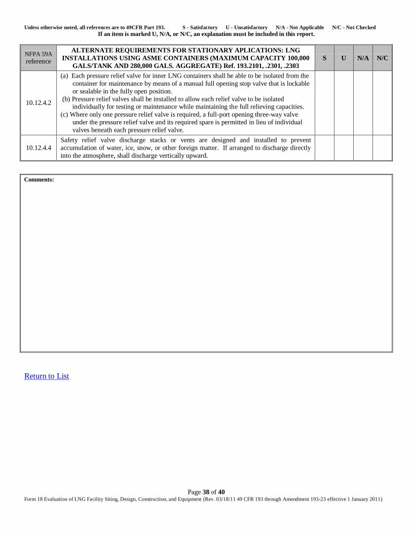
Unless otherwise noted, all references are to 49CFR Part 193. S - Satisfactory U - Unsatisfactory N/A - Not Applicable N/C - Not Checked If an item is marked U, N/A, or N/C, an explanation must be included in this report.
Page 38 of 40 Form 18 Evaluation of LNG Facility Siting, Design, Construction, and Equipment (Rev. 03/18/11 49 CFR 193 through Amendment 193-23 effective 1 January 2011)
NFPA 59A
reference
ALTERNATE REQUIREMENTS FOR STATIONARY APLICATIONS: LNG
INSTALLATIONS USING ASME CONTAINERS (MAXIMUM CAPACITY 100,000
GALS/TANK AND 280,000 GALS. AGGREGATE) Ref. 193.2101, .2301, .2303
S U N/A N/C
10.12.4.2
(a) Each pressure relief valve for inner LNG containers shall be able to be isolated from the
container for maintenance by means of a manual full opening stop valve that is lockable
or sealable in the fully open position.
(b) Pressure relief valves shall be installed to allow each relief valve to be isolated individually for testing or maintenance while maintaining the full relieving capacities.
(c) Where only one pressure relief valve is required, a full-port opening three-way valve
under the pressure relief valve and its required spare is permitted in lieu of individual
valves beneath each pressure relief valve.
10.12.4.4
Safety relief valve discharge stacks or vents are designed and installed to prevent
accumulation of water, ice, snow, or other foreign matter. If arranged to discharge directly
into the atmosphere, shall discharge vertically upward.
Comments:
Return to List
Unless otherwise noted, all references are to 49CFR Part 193. S - Satisfactory U - Unsatisfactory N/A - Not Applicable N/C - Not Checked If an item is marked U, N/A, or N/C, an explanation must be included in this report.
Page 39 of 40 Form 18 Evaluation of LNG Facility Siting, Design, Construction, and Equipment (Rev. 03/18/11 49 CFR 193 through Amendment 193-23 effective 1 January 2011)
Module 14
Construction Acceptance (193.2303); Design & Fabrication (193.2703); Construction, Installation,
Inspection and Testing (193.2705); Records (193.2119); Warning Signs (193.2917)
'193.2303 CONSTRUCTION ACCEPTANCE S U N/A N/C
No component may be placed in service until it passes all applicable inspections and tests prescribed by
Subpart D and NFPA 59A.
Comments:
COMPETENCE AND PERFORMANCE S U N/A N/C
' 193.2703 DESIGN AND FABRICATION
(Demonstrated competence by training or experience)
' 193.2705 CONSTRUCTION, INSTALLATION, INSPECTION, AND TESTING
(Satisfactory performance)
Comments:
'193.2119 RECORDS S U N/A N/C
Each operator shall keep a record of all materials for components, buildings, foundations, and support systems, as necessary to verify that material properties meet the requirements of this part. These records
must be maintained for the life of the item concerned.
Comments:
Unless otherwise noted, all references are to 49CFR Part 193. S - Satisfactory U - Unsatisfactory N/A - Not Applicable N/C - Not Checked If an item is marked U, N/A, or N/C, an explanation must be included in this report.
Page 40 of 40 Form 18 Evaluation of LNG Facility Siting, Design, Construction, and Equipment (Rev. 03/18/11 49 CFR 193 through Amendment 193-23 effective 1 January 2011)
' 193.2917 WARNING SIGNS. S U N/A N/C
(a) Warning signs must be conspicuously placed along each protective enclosure at intervals so that at
least one sign is recognizable at night from a distance of 30m (100 ft.) from any way that could
reasonably be used to approach the enclosure.
(b) Signs must be marked with at least the following on a background of sharply contrasting color: The
words ``NO TRESPASSING'', or words of comparable meaning.
Comments:
NFPA 59A
reference GENERAL and BASIC DESIGN - STATIONARY LNG STORAGE CONTAINERS
Ref. 193.2101, .2303 S U N/A N/C
4.1.1
Prior to initial operation, containers shall be inspected to ensure compliance with the
engineering design and material, fabrication, assembly, and test provisions of this standard.
Exception: ASME containers.
Comments:
Return to List


![11, 1980...(NFPA] Standard 59A (1971 edition), as well as the other applicable requirements of Part 192. Subsequently, the 1972 edition of NFPA 59A was adopted (41 FR 13590).. In the](https://img.pdfslide.us/doc/110x75/60ac9f8c86d5a5085e6fcb37/11-1980-nfpa-standard-59a-1971-edition-as-well-as-the-other-applicable.jpg)


![301-376 Tablolar.pdf · edu pp pp pp pp pp pp pp 7deor v i ] ] ] u o ] À ] ] u ]](https://img.pdfslide.us/doc/110x75/5e39ab3c618e6a17372c0832/301-376-tablolarpdf-edu-pp-pp-pp-pp-pp-pp-pp-7deor-v-i-u-o-u-.jpg)


![Public Input No. 8-NFPA 59A-2013 [ Global Input ] Additional](https://img.pdfslide.us/doc/110x75/584cef3a1a28ab85738fc8c6/public-input-no-8-nfpa-59a-2013-global-input-additional-.jpg)