Embed Size (px)
Citation preview

3 2 1 20 19
9 10 11 12 13
4
5
6
7
8
18
17
16
15
14
NC
2OUT
NC
2IN−
NC
NC
1IN−
NC
1IN+
NC
NC
1O
UT
NC
NC
NC
NC
GN
D
NC
CC
+V
2IN
+
1
2
3
4
8
7
6
5
1OUT
1IN−
1IN+
GND
VCC
2OUT
2IN−
2IN+
LM158, LM158A, LM258, LM258ALM358, LM358A, LM2904, LM2904V
www.ti.com SLOS068S –JUNE 1976–REVISED MAY 2013
Dual Operational Amplifiers
1FEATURES DESCRIPTIONThese devices consist of two independent, high-gain• Wide Supply Rangesfrequency-compensated operational amplifiers– Single Supply: 3 V to 32 V (26 V for designed to operate from a single supply over a wide
LM2904) range of voltages. Operation from split supplies also– Dual Supplies: ±1.5 V to ±16 V (±13 V for is possible if the difference between the two supplies
is 3 V to 32 V (3 V to 26 V for the LM2904), and VCCLM2904)is at least 1.5 V more positive than the input• Low Supply-Current Drain, Independent ofcommon-mode voltage. The low supply-current drainSupply Voltage: 0.7 mA Typ is independent of the magnitude of the supply
• Wide Unity Gain Bandwidth: 0.7MHz voltage.• Common-Mode Input Voltage Range Includes Applications include transducer amplifiers, dcGround, Allowing Direct Sensing Near Ground amplification blocks, and all the conventional• Low Input Bias and Offset Parameters operational amplifier circuits that now can be
implemented more easily in single-supply-voltage– Input Offset Voltage: 3 mV Typsystems. For example, these devices can beA Versions: 2 mV Typ operated directly from the standard 5-V supply used
– Input Offset Current: 2 nA Typ in digital systems and easily can provide the requiredinterface electronics without additional ±5-V supplies.– Input Bias Current: 20 nA Typ
A Versions: 15 nA Typ• Differential Input Voltage Range Equal to
Maximum-Rated Supply Voltage: 32 V (26 V forLM2904)
• Open-Loop Differential Voltage Gain: 100dBTyp
• Internal Frequency Compensation• On Products Compliant to MIL-PRF-38535,
All Parameters Are Tested Unless OtherwiseNoted. On All Other Products, ProductionProcessing Does Not Necessarily IncludeTesting of All Parameters.
LM158, LM158A . . . FK PackageLM158, LM158A . . . JG Package (Top View)
LM258, LM258A . . . D, DGK, or P PackageLM358 . . . D, DGK, P, PS, or PW Package
LM358A . . . D, DGK, P, or PW PackageLM2904 . . . D, DGK, P, PS, or PW Package
(Top View)
NC − No internal connection
1
Please be aware that an important notice concerning availability, standard warranty, and use in critical applications ofTexas Instruments semiconductor products and disclaimers thereto appears at the end of this data sheet.
PRODUCTION DATA information is current as of publication date. Copyright © 1976–2013, Texas Instruments IncorporatedProducts conform to specifications per the terms of the TexasInstruments standard warranty. Production processing does notnecessarily include testing of all parameters.

VCC+
OUT
GND (or VCC−)
To Other Amplifier
IN−
IN+
≈6- Aµ
Current
Regulator
≈6- Aµ
Current
Regulator
≈100- Aµ
Current
Regulator
≈50- Aµ
Current
Regulator
Epi-FET
Diodes
Resistors
Transistors
Capacitors
COMPONENT COUNT
1
2
7
51
2
IN+
IN−OUT
+
−
LM158, LM158A, LM258, LM258ALM358, LM358A, LM2904, LM2904VSLOS068S –JUNE 1976–REVISED MAY 2013 www.ti.com
This integrated circuit can be damaged by ESD. Texas Instruments recommends that all integrated circuits be handled withappropriate precautions. Failure to observe proper handling and installation procedures can cause damage.
ESD damage can range from subtle performance degradation to complete device failure. Precision integrated circuits may be moresusceptible to damage because very small parametric changes could cause the device not to meet its published specifications.
Symbol (Each Amplifier)
Schematic (Each Amplifier)
2 Submit Documentation Feedback Copyright © 1976–2013, Texas Instruments Incorporated
Product Folder Links: LM158 LM258 LM258A LM358 LM358A LM2904 LM2904V

LM158, LM158A, LM258, LM258ALM358, LM358A, LM2904, LM2904V
www.ti.com SLOS068S –JUNE 1976–REVISED MAY 2013
Absolute Maximum Ratingsover operating free-air temperature range (unless otherwise noted) (1)
LM158,LM158ALM258,LM258A LM2904 UNITLM358,LM358ALM2904V
Supply voltage, VCC(2) ±16 or 32 ±13 or 26 V
Differential input voltage, VID(3) ±32 ±26 V
Input voltage, VI (either input) –0.3 to 32 –0.3 to 26 VDuration of output short circuit (one amplifier) to ground at (or below) TA = 25°C, VCC ≤ 15 V (4) Unlimited Unlimited
D package 97 97DGK package 172 172
Package thermal impedance, θJA(4) (5) P package 85 85 °C/W
PS package 95 95PW package 149 149D package 72.2
Package thermal impedance, θJC(6) (7) FK package 5.61 °C/W
JG package 14.5LM158, LM158A –55 to 125LM258, LM258A –25 to 85
Operating free air temperature range. TA °CLM358, LM358A 0 to 70LM2904 –40 to 125 –40 to 125
Operating virtual junction temperature, TJ 150 150 °CCase temperature for 60 seconds FK package 260 °CLead temperature 1,6 mm (1/16 inch) from case for 60 JG package 300 300 °CsecondsStorage temperature range, Tstg –65 to 150 –65 to 150 °C
(1) Stresses beyond those listed under Absolute Maximum Ratings may cause permanent damage to the device. These are stress ratingsonly, and functional operation of the device at these or any other conditions beyond those indicated under Recommended OperatingConditions is not implied. Exposure to absolute-maximum-rated conditions for extended periods may affect device reliability.
(2) All voltage values (except differential voltages and VCC specified for the measurement of IOS) are with respect to the network GND.(3) Differential voltages are at IN+, with respect to IN−.(4) Short circuits from outputs to VCC can cause excessive heating and eventual destruction.(5) Maximum power dissipation is a function of TJ(max), θJA, and TA. The maximum allowable power dissipation at any allowable ambient
temperature is PD = (TJ(max) – TA)/θJA. Operating at the absolute maximum TJ of 150°C can affect reliability.(6) Maximum power dissipation is a function of TJ(max), θJC, and TC. The maximum allowable power dissipation at any allowable case
temperature is PD = (TJ(max) – TC)/θJC. Operating at the absolute maximum TJ of 150°C can affect reliability.(7) The package thermal impedance is calculated in accordance with MIL-STD-883.
Copyright © 1976–2013, Texas Instruments Incorporated Submit Documentation Feedback 3
Product Folder Links: LM158 LM258 LM258A LM358 LM358A LM2904 LM2904V

LM158, LM158A, LM258, LM258ALM358, LM358A, LM2904, LM2904VSLOS068S –JUNE 1976–REVISED MAY 2013 www.ti.com
Electrical Characteristicsat specified free-air temperature, VCC = 5 V (unless otherwise noted)
LM158 LM258 LM358PARAMETER TEST CONDITIONS(1) TA
(2) UNITMIN TYP(3) MAX MIN TYP(3) MAX
25°C 3 5 3 7VCC = 5 V to MAX, VIC = VICRmin,VIO Input offset voltage mV
VO = 1.4 V Full range 7 9
Average temperature coefficient ofαVIO Full range 7 7 µV/°Cinput offset voltage
25°C 2 30 2 50IIO Input offset current VO = 1.4 V nA
Full range 100 150
Average temperature coefficient ofαIIO Full range 10 10 pA/°Cinput offset current
25°C –20 –150 –20 –250IIB Input bias current VO = 1.4 V nA
Full range –300 –500
0 to 0 to25°C
VCC – 1.5 VCC – 1.5VICR Common-mode input voltage range VCC = 5 V to MAX V
0 to 0 toFull range
VCC – 2 VCC – 2
RL ≥ 2 kΩ 25°C VCC – 1.5 VCC – 1.5
RL ≥ 10 kΩ 25°CVOH High-level output voltage V
RL = 2 kΩ Full range 26 26VCC = MAX
RL ≥ 10 kΩ Full range 27 28 27 28
VOL Low-level output voltage RL ≤ 10 kΩ Full range 5 20 5 20 mV
VCC = 15 V 25°C 50 100 25 100Large-signal differential voltage VO = 1 V to 11 V,AVD V/mVamplification Full range 25 15RL ≥ 2 kΩ
VCC= 5 V to MAX,CMRR Common-mode rejection ratio 25°C 70 80 65 80 dBVIC = VICR(min)
Supply-voltage rejection ratiokSVR VCC = 5 V to MAX 25°C 65 100 65 100 dB
(ΔVDD /ΔVIO)
VO1/ VO2 Crosstalk attenuation f = 1 kHz to 20 kHz 25°C 120 120 dB
VCC = 15 V, 25°C –20 –30 –20 –30VID = 1 V, Source
Full range –10 –10VO = 0mA
IO Output current VCC = 15 V, 25°C 10 20 10 20VID = –1 V, Sink
Full range 5 5VO = 15 V
VID = –1 V, VO = 200 mV 25°C 12 30 12 30 μA
VCC at 5 V, VO = 0,IOS Short-circuit output current 25°C ±40 ±60 ±40 ±60 mA
GND at –5 V
VO = 2.5 V, No load Full range 0.7 1.2 0.7 1.2ICC Supply current (two amplifiers) mAVCC = MAX, VO = 0.5 VCC,
Full range 1 2 1 2No load
(1) All characteristics are measured under open-loop conditions, with zero common-mode input voltage, unless otherwise specified. MAXVCC for testing purposes is 26 V for LM2902 and 30 V for the others.
(2) Full range is –55°C to 125°C for LM158, –25°C to 85°C for LM258, and 0°C to 70°C for LM358, and –40°C to 125°C for LM2904 .(3) All typical values are at TA = 25°C
4 Submit Documentation Feedback Copyright © 1976–2013, Texas Instruments Incorporated
Product Folder Links: LM158 LM258 LM258A LM358 LM358A LM2904 LM2904V

LM158, LM158A, LM258, LM258ALM358, LM358A, LM2904, LM2904V
www.ti.com SLOS068S –JUNE 1976–REVISED MAY 2013
Electrical Characteristicsat specified free-air temperature, VCC = 5 V (unless otherwise noted)
LM2904PARAMETER TEST CONDITIONS(1) TA
(2) UNITMIN TYP(3) MAX
25°C 3 7Non-A-suffixVCC = 5 V to MAX, devices Full range 10
VIO Input offset voltage VIC = VICR(min), mV25°C 1 2VO = 1.4 V A-suffix devices
Full range 4
Average temperature coefficient of inputαVIO Full range 7 μV/°Coffset voltage
25°C 2 50Non-V device
Full range 300IIO Input offset current VO = 1.4 V nA
25°C 2 50V-suffix device
Full range 150
Average temperature coefficient of inputαIIO Full range 10 pA/°Coffset current
25°C –20 –250IIB Input bias current VO = 1.4 V nA
Full range –500
0 to25°C
VCC – 1.5VICR Common-mode input voltage range VCC = 5 V to MAX V
0 toFull range
VCC – 2
RL ≥ 10 kΩ 25°C VCC − 1.5
RL = 2 kΩ Full range 22VCC = MAX,Non-V deviceVOH High-level output voltage RL ≥ 10 kΩ Full range 23 24 V
RL = 2 kΩ Full range 26VCC = MAXV-suffix device RL ≥ 10 kΩ Full range 27 28
VOL Low-level output voltage RL ≤ 10 kΩ Full range 5 20 mV
VCC = 15 V, 25°C 25 100AVD Large-signal differential voltage amplification VO = 1 V to 11 V, V/mV
Full range 15RL ≥ 2 kΩ
Non-V device 25°C 50 80VCC = 5V to MAX,CMRR Common-mode rejection ratio dBVIC = VICR(min) V-suffix device 25°C 65 80
Supply-voltage rejection ratiokSVR VCC = 5 V to MAX 25°C 65 100 dB
(ΔVCC /ΔVIO)
VO1/ VO2 Crosstalk attenuation f = 1 kHz to 20 kHz 25°C 120 dB
VCC = 15 V, 25°C –20 –30VID = 1 V, Source
Full range –10VO = 0mA
VCC = 15 V, 25°C 10 20IO Output current VID = –1 V, Sink
Full range 5VO = 15 V
Non-V device 25°C 30VID = –1 V, VO = 200 mV μA
V-suffix device 25°C 12 40
IOS Short-circuit output current VCC at 5 V, VO = 0, GND at −5 V 25°C ±40 ±60 mA
VO = 2.5 V, No load Full range 0.7 1.2ICC Supply current (four amplifiers) mA
VCC = MAX, VO = 0.5 VCC, No load Full range 1 2
(1) All characteristics are measured under open-loop conditions, with zero common-mode input voltage, unless otherwise specified. MAXVCC for testing purposes is 26 V for LM2902 and 32 V for LM2902V.
(2) Full range is –55°C to 125°C for LM158, –25°C to 85°C for LM258, 0°C to 70°C for LM358, and –40°C to 125°C for LM2904.(3) All typical values are at TA = 25°C.
Copyright © 1976–2013, Texas Instruments Incorporated Submit Documentation Feedback 5
Product Folder Links: LM158 LM258 LM258A LM358 LM358A LM2904 LM2904V

LM158, LM158A, LM258, LM258ALM358, LM358A, LM2904, LM2904VSLOS068S –JUNE 1976–REVISED MAY 2013 www.ti.com
Electrical Characteristicsat specified free-air temperature, VCC = 5 V (unless otherwise noted)
LM158A LM258APARAMETER TEST CONDITIONS(1) TA
(1) UNITMIN TYP(2) MAX MIN TYP(2) MAX
VCC = 5 V to 30 V, 25°C 2 2 3VIO Input offset voltage VIC = VICR(min), mV
Full range 4 4VO = 1.4 V
AveragetemperatureαVIO Full range 7 15(3) 7 15 µA/°Ccoefficient of inputoffset voltage
25°C 2 10 2 15IIO Input offset current VO = 1.4 V nA
Full range 30 30
AveragetemperatureαIIO Full range 10 200 10 200 pA/°Ccoefficient of inputoffset current
25°C –15 –50 –15 –80IIB Input bias current VO = 1.4 V nA
Full range –100 –100
0 to 0 to25°C
VCC – 1.5 VCC – 1.5Common-modeVICR VCC = 30 V Vinput voltage range 0 to 0 toFull range
VCC – 2 VCC – 2
RL ≥ 2 kΩ 25°C VCC – 1.5 VCC – 1.5High-level outputVOH RL= 2kΩ Full range 26 26 Vvoltage VCC = 30 V
RL≥ 10kΩ Full range 27 28 27 28
Low-level outputVOL RL ≤ 10 kΩ Full range 5 20 5 20 mVvoltage
Large-signal 25°C 50 100 50 100VCC = 15 V, VO = 1 V to 11 V,AVD differential voltage V/mV
RL ≥ 2 kΩ Full range 25 25amplification
Common-modeCMRR 25°C 70 80 70 80 dBrejection ratio
Supply-voltagerejection ratiokSVR 25°C 65 100 65 100 dB(ΔVD /ΔVIO)
CrosstalkVO1/ VO2 f = 1 kHz to 20 kHz 25°C 120 120 dBattenuation
VCC = 15 V, 25°C –20 –30 –60 –20 –30 −60VID = 1 V, Source
Full range –10 –10VO = 0mA
IO Output current VCC = 15 V, 25°C 10 20 10 20VID = –1 V, Sink
Full range 5 5VO = 15 V
VID = −1 V, VO = 200 mV 25°C 12 30 12 30 μA
VCC at 5 V, GND at –5 V,Short-circuit outputIOS 25°C ±40 ±60 ±40 ±60 mAcurrent VO = 0
VO = 2.5 V, No load Full range 0.7 1.2 0.7 1.2Supply current (fourICC mAVCC = MAX V, VO = 0.5 V,amplifiers) Full range 1 2 1 2
No load
(1) All characteristics are measured under open-loop conditions, with zero common-mode input voltage, unless otherwise specified. MAXVCC for testing purposes is 26 V for LM2904 and 30 V for others.
(2) All typical values are at TA = 25°C.(3) On products compliant to MIL-PRF-38535, this parameter is not production tested.
6 Submit Documentation Feedback Copyright © 1976–2013, Texas Instruments Incorporated
Product Folder Links: LM158 LM258 LM258A LM358 LM358A LM2904 LM2904V

LM158, LM158A, LM258, LM258ALM358, LM358A, LM2904, LM2904V
www.ti.com SLOS068S –JUNE 1976–REVISED MAY 2013
Electrical Characteristicsat specified free-air temperature, VCC = 5 V (unless otherwise noted)
LM358APARAMETER TEST CONDITIONS(1) TA
(2) UNITMIN TYP(3) MAX
VCC = 5 V to 30 V, 25°C 2 3VIO Input offset voltage VIC = VICR(min), mV
Full range 5VO = 1.4 V
Average temperatureαVIO coefficient of input offset Full range 7 20 µA/°C
voltage
25°C 2 30IIO Input offset current VO = 1.4 V nA
Full range 75
Average temperatureαIIO coefficient of input offset Full range 10 300 pA/°C
current
25°C –15 –100IIB Input bias current VO = 1.4 V nA
Full range –200
0 to25°C
VCC – 1.5Common-mode inputVICR VCC = 30 V Vvoltage range 0 toFull range
VCC – 2
RL ≥ 2 kΩ 25°C VCC – 1.5
VOH High-level output voltage RL= 2kΩ Full range 26 VVCC = 30 V
RL≥ 10kΩ Full range 27 28
VOL Low-level output voltage RL ≤ 10 kΩ Full range 5 20 mV
25°C 25 100VCC = 15 V, VO = 1 V to 11 V,Large-signal differentialAVD V/mVvoltage amplification RL ≥ 2 kΩ Full range 15
Common-mode rejectionCMRR 25°C 65 80 dBratio
Supply-voltage rejectionratiokSVR 25°C 65 100 dB(ΔVDD /ΔVIO)
VO1/ VO2 Crosstalk attenuation f = 1 kHz to 20 kHz 25°C 120 dB
VCC = 15 V, 25°C –20 –30 −60VID = 1 V, Source
Full range –10VO = 0mA
IO Output current VCC = 15 V, 25°C 10 20VID = –1 V, Sink
Full range 5VO = 15 V
VID = –1 V, VO = 200 mV 25°C 30 μA
VCC at 5 V, GND at –5 V,IOS Short-circuit output current 25°C ±40 ±60 mA
VO = 0
VO = 2.5 V, No load Full range 0.7 1.2Supply current (fourICC mAVCC = MAX V, VO = 0.5 V,amplifiers) Full range 1 2
No load
(1) All characteristics are measured under open-loop conditions, with zero common-mode input voltage, unless otherwise specified. MAXVCC for testing purposes is 26 V for LM2904 and 30 V for others.
(2) All characteristics are measured under open-loop conditions, with zero common-mode input voltage, unless otherwise specified. MAXVCC for testing purposes is 26 V for LM2904 and 30 V for others.
(3) All typical values are at TA = 25°C.
Operating Conditions, VCC = ±15 V, TA = 25°CPARAMETER TEST CONDITIONS TYP UNIT
SR Slew rate at unity gain RL = 1 MΩ, CL = 30 pF, VI = ±10 V (see Figure 1) 0.3 V/μsB1 Unity-gain bandwidth RL = 1 MΩ, CL = 20 pF (see Figure 1Figure 1) 0.7 MHzVn Equivalent input noise voltage RS = 100 Ω, VI = 0 V, f = 1 kHz (see Figure 2) 40 nV/√Hz
Copyright © 1976–2013, Texas Instruments Incorporated Submit Documentation Feedback 7
Product Folder Links: LM158 LM258 LM258A LM358 LM358A LM2904 LM2904V

VO
−
+
100 Ω
VCC+
VCC−
RS
900 Ω
VI = 0 V
VO
−
+
RLCL
VI
VCC+
VCC−
LM158, LM158A, LM258, LM258ALM358, LM358A, LM2904, LM2904VSLOS068S –JUNE 1976–REVISED MAY 2013 www.ti.com
Figure 1. Unity-Gain Amplifier
Figure 2. Noise-Test Circuit
8 Submit Documentation Feedback Copyright © 1976–2013, Texas Instruments Incorporated
Product Folder Links: LM158 LM258 LM258A LM358 LM358A LM2904 LM2904V

0
20
40
60
80
100
120
140
1 10 100 1,000 10,000 100,000 1,000,000
Vo
ltag
e G
ain
(d
B)
Frequency (Hz)
Open Loop Frequency Response
0
20
40
60
80
100
120
100 1,000 10,000 100,000 1,000,000
dB
Frequency (Hz)
Common Mode Rejection Ratio (differential gain / common mode gain)
0.2
0.22
0.24
0.26
0.28
0.3
0.32
0.34
0.36
0 5 10 15 20 25 30
Su
pp
ly C
urr
ent
in m
A
Supply Voltage
Supply Current (ICC)
-55C
0C
125C
0
20
40
60
80
100
120
140
160
0 5 10 15 20 25 30 35 40
Avo
l V
olt
age
Gai
n (d
B)
V+ Supply Voltage (Vdc)
Voltage Gain
RL=20K
RL=2K
0
5
10
15
0 5 10 15
+/-V
in In
pu
t V
olt
age
(+/-
Vd
c)
V+ OR V- Power Supply Voltage (+/-Vdc)
Input Voltage Range
Negative
Positive
0
2
4
6
8
10
12
14
16
18
20
-55 -35 -15 5 25 45 65 85 105 125
Ib I
np
ut C
urr
ent
(nA
dc)
Ta Temperature (C)
Input Current
5Vdc
15Vdc
30Vdc
LM158, LM158A, LM258, LM258ALM358, LM358A, LM2904, LM2904V
www.ti.com SLOS068S –JUNE 1976–REVISED MAY 2013
Typical Characteristics
Figure 3. Figure 4.
Figure 5. Figure 6.
Figure 7. Min & Max Gain Over Temperature Range Figure 8.
Copyright © 1976–2013, Texas Instruments Incorporated Submit Documentation Feedback 9
Product Folder Links: LM158 LM258 LM258A LM358 LM358A LM2904 LM2904V

0.01
0.1
1
10
0.001 0.01 0.1 1 10 100
Vo
Ou
tpu
t V
olt
age
(Vd
c)
Io Output Sink Current (mAdc)
Output Characteristics Current Sinking
5Vdc
15Vdc
30Vdc
0
10
20
30
40
50
60
70
80
90
-55 -35 -15 5 25 45 65 85 105 125
Io+
Ou
tpu
t Cu
rren
t (m
Ad
c)
Ta Temperature
Current Limiting
0
2.5
5
7.5
10
12.5
15
17.5
20
1 10 100 1000
Vo
Ou
tpu
t S
win
g (V
p-p
)
f Frequency (kHz)
Large Signal Frequency Response
1
2
3
4
5
6
7
8
0.001 0.01 0.1 1 10 100
Vo
Ou
tpu
t V
olt
age
(Vd
c) r
elat
ive
to V
cc
Io Output Sink Current (mAdc)
Output Characteristics Current Sourcing
0
1
2
3
4
0 5 10 15 20 25 30 35 40
Vo
Ou
tpu
t Vo
ltag
e (V
)
t TIME (uS)
Voltage Follower Pulse Response
250
300
350
400
450
500
0 1 2 3 4 5 6 7 8
e0 O
utp
ut V
olt
age
(mV
)
t TIME (uS)
Voltage Follower Pulse Response (Small Signal)
LM158, LM158A, LM258, LM258ALM358, LM358A, LM2904, LM2904VSLOS068S –JUNE 1976–REVISED MAY 2013 www.ti.com
Typical Characteristics (continued)
Figure 9. Figure 10.
Figure 11. Figure 12.
Figure 13. Figure 14.
10 Submit Documentation Feedback Copyright © 1976–2013, Texas Instruments Incorporated
Product Folder Links: LM158 LM258 LM258A LM358 LM358A LM2904 LM2904V

0
20
40
60
80
100
120
140
160
0 5 10 15 20 25 30
Avo
l V
olt
age
Gai
n (
dB
)
V+ Supply Voltage (Vdc)
Voltage Gain (LM2902 Only)
RL=20K
RL=2K
0.00
12.50
25.00
37.50
50.00
0 5 10 15 20 25 30
Iin In
pu
t C
urr
ent
(nA
dc)
V+ Supply Voltage (Vdc)
Input Current (LM2902 Only)
LM158, LM158A, LM258, LM258ALM358, LM358A, LM2904, LM2904V
www.ti.com SLOS068S –JUNE 1976–REVISED MAY 2013
Typical Characteristics (continued)
Figure 15. Figure 16.
Copyright © 1976–2013, Texas Instruments Incorporated Submit Documentation Feedback 11
Product Folder Links: LM158 LM258 LM258A LM358 LM358A LM2904 LM2904V

LM158, LM158A, LM258, LM258ALM358, LM358A, LM2904, LM2904VSLOS068S –JUNE 1976–REVISED MAY 2013 www.ti.com
REVISION HISTORY
Changes from Revision R (July 2010) to Revision S Page
• Converted this data sheet from the QS format to DocZone using the PDF on the web. ..................................................... 1• Updated Features. ................................................................................................................................................................ 1• Added ESD warning. ............................................................................................................................................................ 2• Deleted Ordering Information table. ...................................................................................................................................... 2• Added Package thermal impedance information, θJC for D package. .................................................................................. 3• Added Typical Characteristics Section ................................................................................................................................. 9
12 Submit Documentation Feedback Copyright © 1976–2013, Texas Instruments Incorporated
Product Folder Links: LM158 LM258 LM258A LM358 LM358A LM2904 LM2904V

PACKAGE OPTION ADDENDUM
www.ti.com 9-Mar-2014
Addendum-Page 1
PACKAGING INFORMATION
Orderable Device Status(1)
Package Type PackageDrawing
Pins PackageQty
Eco Plan(2)
Lead/Ball Finish(6)
MSL Peak Temp(3)
Op Temp (°C) Device Marking(4/5)
5962-87710012A ACTIVE LCCC FK 20 1 TBD POST-PLATE N / A for Pkg Type -55 to 125 5962-87710012ALM158FKB
5962-8771001PA ACTIVE CDIP JG 8 1 TBD A42 N / A for Pkg Type -55 to 125 8771001PALM158
5962-87710022A ACTIVE LCCC FK 20 1 TBD POST-PLATE N / A for Pkg Type -55 to 125 5962-87710022ALM158AFKB
5962-8771002PA ACTIVE CDIP JG 8 1 TBD A42 N / A for Pkg Type -55 to 125 8771002PALM158A
LM158AFKB ACTIVE LCCC FK 20 1 TBD POST-PLATE N / A for Pkg Type -55 to 125 5962-87710022ALM158AFKB
LM158AJG ACTIVE CDIP JG 8 1 TBD A42 N / A for Pkg Type -55 to 125 LM158AJG
LM158AJGB ACTIVE CDIP JG 8 1 TBD A42 N / A for Pkg Type -55 to 125 8771002PALM158A
LM158FKB ACTIVE LCCC FK 20 1 TBD POST-PLATE N / A for Pkg Type -55 to 125 5962-87710012ALM158FKB
LM158JG ACTIVE CDIP JG 8 1 TBD A42 N / A for Pkg Type -55 to 125 LM158JG
LM158JGB ACTIVE CDIP JG 8 1 TBD A42 N / A for Pkg Type -55 to 125 8771001PALM158
LM258AD ACTIVE SOIC D 8 75 Green (RoHS& no Sb/Br)
CU NIPDAU Level-1-260C-UNLIM -25 to 85 LM258A
LM258ADE4 ACTIVE SOIC D 8 75 Green (RoHS& no Sb/Br)
CU NIPDAU Level-1-260C-UNLIM -25 to 85 LM258A
LM258ADG4 ACTIVE SOIC D 8 75 Green (RoHS& no Sb/Br)
CU NIPDAU Level-1-260C-UNLIM -25 to 85 LM258A
LM258ADGKR ACTIVE VSSOP DGK 8 2500 Green (RoHS& no Sb/Br)
CU NIPDAU |CU NIPDAUAG
Level-1-260C-UNLIM -25 to 85 (M3L ~ M3P ~ M3S ~ M3U)
LM258ADGKRG4 ACTIVE VSSOP DGK 8 2500 Green (RoHS& no Sb/Br)
CU NIPDAU Level-1-260C-UNLIM -25 to 85 (M3L ~ M3P ~ M3S ~ M3U)
LM258ADR ACTIVE SOIC D 8 2500 Green (RoHS& no Sb/Br)
CU NIPDAU | CU SN Level-1-260C-UNLIM -25 to 85 LM258A

PACKAGE OPTION ADDENDUM
www.ti.com 9-Mar-2014
Addendum-Page 2
Orderable Device Status(1)
Package Type PackageDrawing
Pins PackageQty
Eco Plan(2)
Lead/Ball Finish(6)
MSL Peak Temp(3)
Op Temp (°C) Device Marking(4/5)
LM258ADRE4 ACTIVE SOIC D 8 2500 Green (RoHS& no Sb/Br)
CU NIPDAU Level-1-260C-UNLIM -25 to 85 LM258A
LM258ADRG4 ACTIVE SOIC D 8 2500 Green (RoHS& no Sb/Br)
CU NIPDAU Level-1-260C-UNLIM -25 to 85 LM258A
LM258AP ACTIVE PDIP P 8 50 Pb-Free(RoHS)
CU NIPDAU N / A for Pkg Type -25 to 85 LM258AP
LM258APE4 ACTIVE PDIP P 8 50 Pb-Free(RoHS)
CU NIPDAU N / A for Pkg Type -25 to 85 LM258AP
LM258D ACTIVE SOIC D 8 75 Green (RoHS& no Sb/Br)
CU NIPDAU Level-1-260C-UNLIM -25 to 85 LM258
LM258DE4 ACTIVE SOIC D 8 75 Green (RoHS& no Sb/Br)
CU NIPDAU Level-1-260C-UNLIM -25 to 85 LM258
LM258DG4 ACTIVE SOIC D 8 75 Green (RoHS& no Sb/Br)
CU NIPDAU Level-1-260C-UNLIM -25 to 85 LM258
LM258DGKR ACTIVE VSSOP DGK 8 2500 Green (RoHS& no Sb/Br)
CU NIPDAU |CU NIPDAUAG
Level-1-260C-UNLIM -25 to 85 (M2L ~ M2P ~ M2S ~ M2U)
LM258DGKRG4 ACTIVE VSSOP DGK 8 2500 Green (RoHS& no Sb/Br)
CU NIPDAU Level-1-260C-UNLIM -25 to 85 (M2L ~ M2P ~ M2S ~ M2U)
LM258DR ACTIVE SOIC D 8 2500 Green (RoHS& no Sb/Br)
CU NIPDAU | CU SN Level-1-260C-UNLIM -25 to 85 LM258
LM258DRE4 ACTIVE SOIC D 8 Green (RoHS& no Sb/Br)
CU NIPDAU Level-1-260C-UNLIM -25 to 85 LM258
LM258DRG3 ACTIVE SOIC D 8 2500 Green (RoHS& no Sb/Br)
CU SN Level-1-260C-UNLIM -25 to 85 LM258
LM258DRG4 ACTIVE SOIC D 8 2500 Green (RoHS& no Sb/Br)
CU NIPDAU Level-1-260C-UNLIM -25 to 85 LM258
LM258P ACTIVE PDIP P 8 50 Pb-Free(RoHS)
CU NIPDAU N / A for Pkg Type -25 to 85 LM258P
LM258PE4 ACTIVE PDIP P 8 50 Pb-Free(RoHS)
CU NIPDAU N / A for Pkg Type -25 to 85 LM258P
LM2904AVQDR ACTIVE SOIC D 8 2500 Green (RoHS& no Sb/Br)
CU NIPDAU Level-1-260C-UNLIM -40 to 125 L2904AV
LM2904AVQDRG4 ACTIVE SOIC D 8 2500 Green (RoHS& no Sb/Br)
CU NIPDAU Level-1-260C-UNLIM -40 to 125 L2904AV
LM2904AVQPWR ACTIVE TSSOP PW 8 2000 Green (RoHS& no Sb/Br)
CU NIPDAU Level-1-260C-UNLIM -40 to 125 L2904AV

PACKAGE OPTION ADDENDUM
www.ti.com 9-Mar-2014
Addendum-Page 3
Orderable Device Status(1)
Package Type PackageDrawing
Pins PackageQty
Eco Plan(2)
Lead/Ball Finish(6)
MSL Peak Temp(3)
Op Temp (°C) Device Marking(4/5)
LM2904AVQPWRG4 ACTIVE TSSOP PW 8 2000 Green (RoHS& no Sb/Br)
CU NIPDAU Level-1-260C-UNLIM -40 to 125 L2904AV
LM2904D ACTIVE SOIC D 8 75 Green (RoHS& no Sb/Br)
CU NIPDAU Level-1-260C-UNLIM -40 to 125 LM2904
LM2904DE4 ACTIVE SOIC D 8 75 Green (RoHS& no Sb/Br)
CU NIPDAU Level-1-260C-UNLIM -40 to 125 LM2904
LM2904DG4 ACTIVE SOIC D 8 75 Green (RoHS& no Sb/Br)
CU NIPDAU Level-1-260C-UNLIM -40 to 125 LM2904
LM2904DGKR ACTIVE VSSOP DGK 8 2500 Green (RoHS& no Sb/Br)
CU NIPDAU |CU NIPDAUAG
Level-1-260C-UNLIM -40 to 125 (MBL ~ MBP ~ MBS ~ MBU)
LM2904DGKRG4 ACTIVE VSSOP DGK 8 2500 Green (RoHS& no Sb/Br)
CU NIPDAU Level-1-260C-UNLIM -40 to 125 (MBL ~ MBP ~ MBS ~ MBU)
LM2904DR ACTIVE SOIC D 8 2500 Green (RoHS& no Sb/Br)
CU NIPDAU | CU SN Level-1-260C-UNLIM -40 to 125 LM2904
LM2904DRE4 ACTIVE SOIC D 8 2500 Green (RoHS& no Sb/Br)
CU NIPDAU Level-1-260C-UNLIM -40 to 125 LM2904
LM2904DRG3 ACTIVE SOIC D 8 2500 Green (RoHS& no Sb/Br)
CU SN Level-1-260C-UNLIM -40 to 125 LM2904
LM2904DRG4 ACTIVE SOIC D 8 2500 Green (RoHS& no Sb/Br)
CU NIPDAU Level-1-260C-UNLIM -40 to 125 LM2904
LM2904P ACTIVE PDIP P 8 50 Pb-Free(RoHS)
CU NIPDAU N / A for Pkg Type -40 to 125 LM2904P
LM2904PE4 ACTIVE PDIP P 8 50 Pb-Free(RoHS)
CU NIPDAU N / A for Pkg Type -40 to 125 LM2904P
LM2904PSR ACTIVE SO PS 8 2000 Green (RoHS& no Sb/Br)
CU NIPDAU Level-1-260C-UNLIM -40 to 125 L2904
LM2904PSRE4 ACTIVE SO PS 8 2000 Green (RoHS& no Sb/Br)
CU NIPDAU Level-1-260C-UNLIM -40 to 125 L2904
LM2904PSRG4 ACTIVE SO PS 8 2000 Green (RoHS& no Sb/Br)
CU NIPDAU Level-1-260C-UNLIM -40 to 125 L2904
LM2904PW ACTIVE TSSOP PW 8 150 Green (RoHS& no Sb/Br)
CU NIPDAU Level-1-260C-UNLIM -40 to 125 L2904
LM2904PWE4 ACTIVE TSSOP PW 8 150 Green (RoHS& no Sb/Br)
CU NIPDAU Level-1-260C-UNLIM -40 to 125 L2904
LM2904PWG4 ACTIVE TSSOP PW 8 150 Green (RoHS& no Sb/Br)
CU NIPDAU Level-1-260C-UNLIM -40 to 125 L2904

PACKAGE OPTION ADDENDUM
www.ti.com 9-Mar-2014
Addendum-Page 4
Orderable Device Status(1)
Package Type PackageDrawing
Pins PackageQty
Eco Plan(2)
Lead/Ball Finish(6)
MSL Peak Temp(3)
Op Temp (°C) Device Marking(4/5)
LM2904PWLE OBSOLETE TSSOP PW 8 TBD Call TI Call TI -40 to 125
LM2904PWR ACTIVE TSSOP PW 8 2000 Green (RoHS& no Sb/Br)
CU NIPDAU | CU SN Level-1-260C-UNLIM -40 to 125 L2904
LM2904PWRG3 ACTIVE TSSOP PW 8 2000 Green (RoHS& no Sb/Br)
CU SN Level-1-260C-UNLIM -40 to 125 L2904
LM2904QD OBSOLETE SOIC D 8 TBD Call TI Call TI -40 to 125
LM2904QDR ACTIVE SOIC D 8 2500 Green (RoHS& no Sb/Br)
CU NIPDAU Level-1-260C-UNLIM -40 to 125 2904Q1
LM2904QDRG4 ACTIVE SOIC D 8 2500 Green (RoHS& no Sb/Br)
CU NIPDAU Level-1-260C-UNLIM -40 to 125 2904Q1
LM2904QP OBSOLETE PDIP P 8 TBD Call TI Call TI -40 to 125
LM2904VQDR ACTIVE SOIC D 8 2500 Green (RoHS& no Sb/Br)
CU NIPDAU Level-1-260C-UNLIM -40 to 125 L2904V
LM2904VQDRG4 ACTIVE SOIC D 8 2500 Green (RoHS& no Sb/Br)
CU NIPDAU Level-1-260C-UNLIM -40 to 125 L2904V
LM2904VQPWR ACTIVE TSSOP PW 8 2000 Green (RoHS& no Sb/Br)
CU NIPDAU Level-1-260C-UNLIM -40 to 125 L2904V
LM2904VQPWRG4 ACTIVE TSSOP PW 8 2000 Green (RoHS& no Sb/Br)
CU NIPDAU Level-1-260C-UNLIM -40 to 125 L2904V
LM358AD ACTIVE SOIC D 8 75 Green (RoHS& no Sb/Br)
CU NIPDAU Level-1-260C-UNLIM 0 to 70 LM358A
LM358ADE4 ACTIVE SOIC D 8 75 Green (RoHS& no Sb/Br)
CU NIPDAU Level-1-260C-UNLIM 0 to 70 LM358A
LM358ADG4 ACTIVE SOIC D 8 75 Green (RoHS& no Sb/Br)
CU NIPDAU Level-1-260C-UNLIM 0 to 70 LM358A
LM358ADGKR ACTIVE VSSOP DGK 8 2500 Green (RoHS& no Sb/Br)
CU NIPDAU |CU NIPDAUAG
Level-1-260C-UNLIM 0 to 70 (M6L ~ M6P ~ M6S ~ M6U)
LM358ADGKRG4 ACTIVE VSSOP DGK 8 2500 Green (RoHS& no Sb/Br)
CU NIPDAU Level-1-260C-UNLIM 0 to 70 (M6L ~ M6P ~ M6S ~ M6U)
LM358ADR ACTIVE SOIC D 8 2500 Green (RoHS& no Sb/Br)
CU NIPDAU | CU SN Level-1-260C-UNLIM 0 to 70 LM358A
LM358ADRE4 ACTIVE SOIC D 8 2500 Green (RoHS& no Sb/Br)
CU NIPDAU Level-1-260C-UNLIM 0 to 70 LM358A
LM358ADRG4 ACTIVE SOIC D 8 2500 Green (RoHS& no Sb/Br)
CU NIPDAU Level-1-260C-UNLIM 0 to 70 LM358A

PACKAGE OPTION ADDENDUM
www.ti.com 9-Mar-2014
Addendum-Page 5
Orderable Device Status(1)
Package Type PackageDrawing
Pins PackageQty
Eco Plan(2)
Lead/Ball Finish(6)
MSL Peak Temp(3)
Op Temp (°C) Device Marking(4/5)
LM358AP ACTIVE PDIP P 8 50 Pb-Free(RoHS)
CU NIPDAU N / A for Pkg Type 0 to 70 LM358AP
LM358APE4 ACTIVE PDIP P 8 50 Pb-Free(RoHS)
CU NIPDAU N / A for Pkg Type 0 to 70 LM358AP
LM358APW ACTIVE TSSOP PW 8 150 Green (RoHS& no Sb/Br)
CU NIPDAU Level-1-260C-UNLIM 0 to 70 L358A
LM358APWE4 ACTIVE TSSOP PW 8 150 Green (RoHS& no Sb/Br)
CU NIPDAU Level-1-260C-UNLIM 0 to 70 L358A
LM358APWG4 ACTIVE TSSOP PW 8 150 Green (RoHS& no Sb/Br)
CU NIPDAU Level-1-260C-UNLIM 0 to 70 L358A
LM358APWR ACTIVE TSSOP PW 8 2000 Green (RoHS& no Sb/Br)
CU NIPDAU | CU SN Level-1-260C-UNLIM 0 to 70 L358A
LM358APWRE4 ACTIVE TSSOP PW 8 2000 Green (RoHS& no Sb/Br)
CU NIPDAU Level-1-260C-UNLIM 0 to 70 L358A
LM358APWRG4 ACTIVE TSSOP PW 8 2000 Green (RoHS& no Sb/Br)
CU NIPDAU Level-1-260C-UNLIM 0 to 70 L358A
LM358D ACTIVE SOIC D 8 75 Green (RoHS& no Sb/Br)
CU NIPDAU Level-1-260C-UNLIM 0 to 70 LM358
LM358DE4 ACTIVE SOIC D 8 75 Green (RoHS& no Sb/Br)
CU NIPDAU Level-1-260C-UNLIM 0 to 70 LM358
LM358DG4 ACTIVE SOIC D 8 75 Green (RoHS& no Sb/Br)
CU NIPDAU Level-1-260C-UNLIM 0 to 70 LM358
LM358DGKR ACTIVE VSSOP DGK 8 2500 Green (RoHS& no Sb/Br)
CU NIPDAU |CU NIPDAUAG
Level-1-260C-UNLIM 0 to 70 (M5L ~ M5P ~ M5S ~ M5U)
LM358DGKRG4 ACTIVE VSSOP DGK 8 2500 Green (RoHS& no Sb/Br)
CU NIPDAU Level-1-260C-UNLIM 0 to 70 (M5L ~ M5P ~ M5S ~ M5U)
LM358DR ACTIVE SOIC D 8 2500 Green (RoHS& no Sb/Br)
CU NIPDAU | CU SN Level-1-260C-UNLIM 0 to 70 LM358
LM358DRE4 ACTIVE SOIC D 8 2500 Green (RoHS& no Sb/Br)
CU NIPDAU Level-1-260C-UNLIM 0 to 70 LM358
LM358DRG3 ACTIVE SOIC D 8 2500 Green (RoHS& no Sb/Br)
CU SN Level-1-260C-UNLIM 0 to 70 LM358
LM358DRG4 ACTIVE SOIC D 8 2500 Green (RoHS& no Sb/Br)
CU NIPDAU Level-1-260C-UNLIM 0 to 70 LM358
LM358P ACTIVE PDIP P 8 50 Green (RoHS& no Sb/Br)
CU NIPDAU | CU SN Level-1-260C-UNLIM 0 to 70 LM358P

PACKAGE OPTION ADDENDUM
www.ti.com 9-Mar-2014
Addendum-Page 6
Orderable Device Status(1)
Package Type PackageDrawing
Pins PackageQty
Eco Plan(2)
Lead/Ball Finish(6)
MSL Peak Temp(3)
Op Temp (°C) Device Marking(4/5)
LM358PE3 ACTIVE PDIP P 8 50 Pb-Free(RoHS)
CU SN N / A for Pkg Type 0 to 70 LM358P
LM358PE4 ACTIVE PDIP P 8 50 Pb-Free(RoHS)
CU NIPDAU N / A for Pkg Type 0 to 70 LM358P
LM358PSLE OBSOLETE SO PS 8 TBD Call TI Call TI 0 to 70
LM358PSR ACTIVE SO PS 8 2000 Green (RoHS& no Sb/Br)
CU NIPDAU Level-1-260C-UNLIM 0 to 70 L358
LM358PSRE4 ACTIVE SO PS 8 2000 Green (RoHS& no Sb/Br)
CU NIPDAU Level-1-260C-UNLIM 0 to 70 L358
LM358PSRG4 ACTIVE SO PS 8 2000 Green (RoHS& no Sb/Br)
CU NIPDAU Level-1-260C-UNLIM 0 to 70 L358
LM358PW ACTIVE TSSOP PW 8 150 Green (RoHS& no Sb/Br)
CU NIPDAU Level-1-260C-UNLIM 0 to 70 L358
LM358PWE4 ACTIVE TSSOP PW 8 150 Green (RoHS& no Sb/Br)
CU NIPDAU Level-1-260C-UNLIM 0 to 70 L358
LM358PWG4 ACTIVE TSSOP PW 8 150 Green (RoHS& no Sb/Br)
CU NIPDAU Level-1-260C-UNLIM 0 to 70 L358
LM358PWLE OBSOLETE TSSOP PW 8 TBD Call TI Call TI 0 to 70
LM358PWR ACTIVE TSSOP PW 8 2000 Green (RoHS& no Sb/Br)
CU NIPDAU | CU SN Level-1-260C-UNLIM 0 to 70 L358
LM358PWRE4 ACTIVE TSSOP PW 8 2000 Green (RoHS& no Sb/Br)
CU NIPDAU Level-1-260C-UNLIM 0 to 70 L358
LM358PWRG3 ACTIVE TSSOP PW 8 2000 Green (RoHS& no Sb/Br)
CU SN Level-1-260C-UNLIM 0 to 70 L358
LM358PWRG4 ACTIVE TSSOP PW 8 2000 Green (RoHS& no Sb/Br)
CU NIPDAU Level-1-260C-UNLIM 0 to 70 L358
(1) The marketing status values are defined as follows:ACTIVE: Product device recommended for new designs.LIFEBUY: TI has announced that the device will be discontinued, and a lifetime-buy period is in effect.NRND: Not recommended for new designs. Device is in production to support existing customers, but TI does not recommend using this part in a new design.PREVIEW: Device has been announced but is not in production. Samples may or may not be available.OBSOLETE: TI has discontinued the production of the device.
(2) Eco Plan - The planned eco-friendly classification: Pb-Free (RoHS), Pb-Free (RoHS Exempt), or Green (RoHS & no Sb/Br) - please check http://www.ti.com/productcontent for the latest availabilityinformation and additional product content details.TBD: The Pb-Free/Green conversion plan has not been defined.

PACKAGE OPTION ADDENDUM
www.ti.com 9-Mar-2014
Addendum-Page 7
Pb-Free (RoHS): TI's terms "Lead-Free" or "Pb-Free" mean semiconductor products that are compatible with the current RoHS requirements for all 6 substances, including the requirement thatlead not exceed 0.1% by weight in homogeneous materials. Where designed to be soldered at high temperatures, TI Pb-Free products are suitable for use in specified lead-free processes.Pb-Free (RoHS Exempt): This component has a RoHS exemption for either 1) lead-based flip-chip solder bumps used between the die and package, or 2) lead-based die adhesive used betweenthe die and leadframe. The component is otherwise considered Pb-Free (RoHS compatible) as defined above.Green (RoHS & no Sb/Br): TI defines "Green" to mean Pb-Free (RoHS compatible), and free of Bromine (Br) and Antimony (Sb) based flame retardants (Br or Sb do not exceed 0.1% by weightin homogeneous material)
(3) MSL, Peak Temp. - The Moisture Sensitivity Level rating according to the JEDEC industry standard classifications, and peak solder temperature.
(4) There may be additional marking, which relates to the logo, the lot trace code information, or the environmental category on the device.
(5) Multiple Device Markings will be inside parentheses. Only one Device Marking contained in parentheses and separated by a "~" will appear on a device. If a line is indented then it is a continuationof the previous line and the two combined represent the entire Device Marking for that device.
(6) Lead/Ball Finish - Orderable Devices may have multiple material finish options. Finish options are separated by a vertical ruled line. Lead/Ball Finish values may wrap to two lines if the finishvalue exceeds the maximum column width.
Important Information and Disclaimer:The information provided on this page represents TI's knowledge and belief as of the date that it is provided. TI bases its knowledge and belief on informationprovided by third parties, and makes no representation or warranty as to the accuracy of such information. Efforts are underway to better integrate information from third parties. TI has taken andcontinues to take reasonable steps to provide representative and accurate information but may not have conducted destructive testing or chemical analysis on incoming materials and chemicals.TI and TI suppliers consider certain information to be proprietary, and thus CAS numbers and other limited information may not be available for release.
In no event shall TI's liability arising out of such information exceed the total purchase price of the TI part(s) at issue in this document sold by TI to Customer on an annual basis.
OTHER QUALIFIED VERSIONS OF LM258A, LM2904 :
• Automotive: LM2904-Q1
• Enhanced Product: LM258A-EP
NOTE: Qualified Version Definitions:
• Automotive - Q100 devices qualified for high-reliability automotive applications targeting zero defects
• Enhanced Product - Supports Defense, Aerospace and Medical Applications

TAPE AND REEL INFORMATION
*All dimensions are nominal
Device PackageType
PackageDrawing
Pins SPQ ReelDiameter
(mm)
ReelWidth
W1 (mm)
A0(mm)
B0(mm)
K0(mm)
P1(mm)
W(mm)
Pin1Quadrant
LM258ADGKR VSSOP DGK 8 2500 330.0 12.4 5.3 3.4 1.4 8.0 12.0 Q1
LM258ADGKR VSSOP DGK 8 2500 330.0 12.4 5.3 3.4 1.4 8.0 12.0 Q1
LM258ADR SOIC D 8 2500 330.0 12.4 6.4 5.2 2.1 8.0 12.0 Q1
LM258ADR SOIC D 8 2500 330.0 12.4 6.4 5.2 2.1 8.0 12.0 Q1
LM258ADRG4 SOIC D 8 2500 330.0 12.4 6.4 5.2 2.1 8.0 12.0 Q1
LM258ADRG4 SOIC D 8 2500 330.0 12.4 6.4 5.2 2.1 8.0 12.0 Q1
LM258DGKR VSSOP DGK 8 2500 330.0 12.4 5.3 3.4 1.4 8.0 12.0 Q1
LM258DGKR VSSOP DGK 8 2500 330.0 12.4 5.3 3.4 1.4 8.0 12.0 Q1
LM258DR SOIC D 8 2500 330.0 12.4 6.4 5.2 2.1 8.0 12.0 Q1
LM258DR SOIC D 8 2500 330.0 12.8 6.4 5.2 2.1 8.0 12.0 Q1
LM258DR SOIC D 8 2500 330.0 12.4 6.4 5.2 2.1 8.0 12.0 Q1
LM258DRG3 SOIC D 8 2500 330.0 12.8 6.4 5.2 2.1 8.0 12.0 Q1
LM258DRG4 SOIC D 8 2500 330.0 12.4 6.4 5.2 2.1 8.0 12.0 Q1
LM2904AVQPWR TSSOP PW 8 2000 330.0 12.4 7.0 3.6 1.6 8.0 12.0 Q1
LM2904AVQPWRG4 TSSOP PW 8 2000 330.0 12.4 7.0 3.6 1.6 8.0 12.0 Q1
LM2904DGKR VSSOP DGK 8 2500 330.0 12.4 5.3 3.4 1.4 8.0 12.0 Q1
LM2904DGKR VSSOP DGK 8 2500 330.0 12.4 5.3 3.4 1.4 8.0 12.0 Q1
LM2904DR SOIC D 8 2500 330.0 12.4 6.4 5.2 2.1 8.0 12.0 Q1
PACKAGE MATERIALS INFORMATION
www.ti.com 11-Feb-2014
Pack Materials-Page 1

Device PackageType
PackageDrawing
Pins SPQ ReelDiameter
(mm)
ReelWidth
W1 (mm)
A0(mm)
B0(mm)
K0(mm)
P1(mm)
W(mm)
Pin1Quadrant
LM2904DR SOIC D 8 2500 330.0 12.4 6.4 5.2 2.1 8.0 12.0 Q1
LM2904DRG3 SOIC D 8 2500 330.0 12.8 6.4 5.2 2.1 8.0 12.0 Q1
LM2904DRG4 SOIC D 8 2500 330.0 12.4 6.4 5.2 2.1 8.0 12.0 Q1
LM2904DRG4 SOIC D 8 2500 330.0 12.4 6.4 5.2 2.1 8.0 12.0 Q1
LM2904PSR SO PS 8 2000 330.0 16.4 8.2 6.6 2.5 12.0 16.0 Q1
LM2904PWR TSSOP PW 8 2000 330.0 12.4 7.0 3.6 1.6 8.0 12.0 Q1
LM2904PWRG3 TSSOP PW 8 2000 330.0 12.4 7.0 3.6 1.6 8.0 12.0 Q1
LM2904QDR SOIC D 8 2500 330.0 12.4 6.4 5.2 2.1 8.0 12.0 Q1
LM2904VQPWRG4 TSSOP PW 8 2000 330.0 12.4 7.0 3.6 1.6 8.0 12.0 Q1
LM358ADGKR VSSOP DGK 8 2500 330.0 12.4 5.3 3.4 1.4 8.0 12.0 Q1
LM358ADGKR VSSOP DGK 8 2500 330.0 12.4 5.3 3.4 1.4 8.0 12.0 Q1
LM358ADR SOIC D 8 2500 330.0 12.8 6.4 5.2 2.1 8.0 12.0 Q1
LM358ADR SOIC D 8 2500 330.0 12.4 6.4 5.2 2.1 8.0 12.0 Q1
LM358ADRG4 SOIC D 8 2500 330.0 12.4 6.4 5.2 2.1 8.0 12.0 Q1
LM358ADRG4 SOIC D 8 2500 330.0 12.4 6.4 5.2 2.1 8.0 12.0 Q1
LM358APWR TSSOP PW 8 2000 330.0 12.4 7.0 3.6 1.6 8.0 12.0 Q1
LM358APWR TSSOP PW 8 2000 330.0 12.4 7.0 3.6 1.6 8.0 12.0 Q1
LM358DGKR VSSOP DGK 8 2500 330.0 12.4 5.3 3.4 1.4 8.0 12.0 Q1
LM358DGKR VSSOP DGK 8 2500 330.0 12.4 5.3 3.4 1.4 8.0 12.0 Q1
LM358DR SOIC D 8 2500 330.0 12.4 6.4 5.2 2.1 8.0 12.0 Q1
LM358DR SOIC D 8 2500 330.0 12.4 6.4 5.2 2.1 8.0 12.0 Q1
LM358DRG3 SOIC D 8 2500 330.0 12.8 6.4 5.2 2.1 8.0 12.0 Q1
LM358DRG4 SOIC D 8 2500 330.0 12.4 6.4 5.2 2.1 8.0 12.0 Q1
LM358DRG4 SOIC D 8 2500 330.0 12.4 6.4 5.2 2.1 8.0 12.0 Q1
LM358PSR SO PS 8 2000 330.0 16.4 8.2 6.6 2.5 12.0 16.0 Q1
LM358PWR TSSOP PW 8 2000 330.0 12.4 7.0 3.6 1.6 8.0 12.0 Q1
LM358PWRG3 TSSOP PW 8 2000 330.0 12.4 7.0 3.6 1.6 8.0 12.0 Q1
PACKAGE MATERIALS INFORMATION
www.ti.com 11-Feb-2014
Pack Materials-Page 2

*All dimensions are nominal
Device Package Type Package Drawing Pins SPQ Length (mm) Width (mm) Height (mm)
LM258ADGKR VSSOP DGK 8 2500 364.0 364.0 27.0
LM258ADGKR VSSOP DGK 8 2500 332.0 358.0 35.0
LM258ADR SOIC D 8 2500 367.0 367.0 35.0
LM258ADR SOIC D 8 2500 340.5 338.1 20.6
LM258ADRG4 SOIC D 8 2500 367.0 367.0 35.0
LM258ADRG4 SOIC D 8 2500 340.5 338.1 20.6
LM258DGKR VSSOP DGK 8 2500 332.0 358.0 35.0
LM258DGKR VSSOP DGK 8 2500 364.0 364.0 27.0
LM258DR SOIC D 8 2500 367.0 367.0 35.0
LM258DR SOIC D 8 2500 364.0 364.0 27.0
LM258DR SOIC D 8 2500 340.5 338.1 20.6
LM258DRG3 SOIC D 8 2500 364.0 364.0 27.0
LM258DRG4 SOIC D 8 2500 367.0 367.0 35.0
LM2904AVQPWR TSSOP PW 8 2000 367.0 367.0 35.0
LM2904AVQPWRG4 TSSOP PW 8 2000 367.0 367.0 35.0
LM2904DGKR VSSOP DGK 8 2500 364.0 364.0 27.0
LM2904DGKR VSSOP DGK 8 2500 332.0 358.0 35.0
LM2904DR SOIC D 8 2500 340.5 338.1 20.6
LM2904DR SOIC D 8 2500 367.0 367.0 35.0
LM2904DRG3 SOIC D 8 2500 364.0 364.0 27.0
PACKAGE MATERIALS INFORMATION
www.ti.com 11-Feb-2014
Pack Materials-Page 3

Device Package Type Package Drawing Pins SPQ Length (mm) Width (mm) Height (mm)
LM2904DRG4 SOIC D 8 2500 340.5 338.1 20.6
LM2904DRG4 SOIC D 8 2500 367.0 367.0 35.0
LM2904PSR SO PS 8 2000 367.0 367.0 38.0
LM2904PWR TSSOP PW 8 2000 364.0 364.0 27.0
LM2904PWRG3 TSSOP PW 8 2000 364.0 364.0 27.0
LM2904QDR SOIC D 8 2500 367.0 367.0 35.0
LM2904VQPWRG4 TSSOP PW 8 2000 367.0 367.0 35.0
LM358ADGKR VSSOP DGK 8 2500 364.0 364.0 27.0
LM358ADGKR VSSOP DGK 8 2500 332.0 358.0 35.0
LM358ADR SOIC D 8 2500 364.0 364.0 27.0
LM358ADR SOIC D 8 2500 340.5 338.1 20.6
LM358ADRG4 SOIC D 8 2500 340.5 338.1 20.6
LM358ADRG4 SOIC D 8 2500 367.0 367.0 35.0
LM358APWR TSSOP PW 8 2000 367.0 367.0 35.0
LM358APWR TSSOP PW 8 2000 364.0 364.0 27.0
LM358DGKR VSSOP DGK 8 2500 332.0 358.0 35.0
LM358DGKR VSSOP DGK 8 2500 364.0 364.0 27.0
LM358DR SOIC D 8 2500 367.0 367.0 35.0
LM358DR SOIC D 8 2500 340.5 338.1 20.6
LM358DRG3 SOIC D 8 2500 364.0 364.0 27.0
LM358DRG4 SOIC D 8 2500 340.5 338.1 20.6
LM358DRG4 SOIC D 8 2500 367.0 367.0 35.0
LM358PSR SO PS 8 2000 367.0 367.0 38.0
LM358PWR TSSOP PW 8 2000 364.0 364.0 27.0
LM358PWRG3 TSSOP PW 8 2000 364.0 364.0 27.0
PACKAGE MATERIALS INFORMATION
www.ti.com 11-Feb-2014
Pack Materials-Page 4

MECHANICAL DATA
MCER001A – JANUARY 1995 – REVISED JANUARY 1997
POST OFFICE BOX 655303 • DALLAS, TEXAS 75265
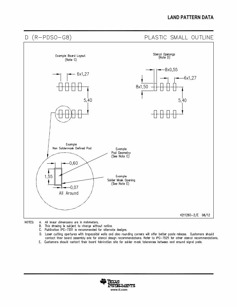
JG (R-GDIP-T8) CERAMIC DUAL-IN-LINE
0.310 (7,87)0.290 (7,37)
0.014 (0,36)0.008 (0,20)
Seating Plane
4040107/C 08/96
5
40.065 (1,65)0.045 (1,14)
8
1
0.020 (0,51) MIN
0.400 (10,16)0.355 (9,00)
0.015 (0,38)0.023 (0,58)
0.063 (1,60)0.015 (0,38)
0.200 (5,08) MAX
0.130 (3,30) MIN
0.245 (6,22)0.280 (7,11)
0.100 (2,54)
0°–15°
NOTES: A. All linear dimensions are in inches (millimeters).B. This drawing is subject to change without notice.C. This package can be hermetically sealed with a ceramic lid using glass frit.D. Index point is provided on cap for terminal identification.E. Falls within MIL STD 1835 GDIP1-T8


IMPORTANT NOTICETexas Instruments Incorporated and its subsidiaries (TI) reserve the right to make corrections, enhancements, improvements and otherchanges to its semiconductor products and services per JESD46, latest issue, and to discontinue any product or service per JESD48, latestissue. Buyers should obtain the latest relevant information before placing orders and should verify that such information is current andcomplete. All semiconductor products (also referred to herein as “components”) are sold subject to TI’s terms and conditions of salesupplied at the time of order acknowledgment.TI warrants performance of its components to the specifications applicable at the time of sale, in accordance with the warranty in TI’s termsand conditions of sale of semiconductor products. Testing and other quality control techniques are used to the extent TI deems necessaryto support this warranty. Except where mandated by applicable law, testing of all parameters of each component is not necessarilyperformed.TI assumes no liability for applications assistance or the design of Buyers’ products. Buyers are responsible for their products andapplications using TI components. To minimize the risks associated with Buyers’ products and applications, Buyers should provideadequate design and operating safeguards.TI does not warrant or represent that any license, either express or implied, is granted under any patent right, copyright, mask work right, orother intellectual property right relating to any combination, machine, or process in which TI components or services are used. Informationpublished by TI regarding third-party products or services does not constitute a license to use such products or services or a warranty orendorsement thereof. Use of such information may require a license from a third party under the patents or other intellectual property of thethird party, or a license from TI under the patents or other intellectual property of TI.Reproduction of significant portions of TI information in TI data books or data sheets is permissible only if reproduction is without alterationand is accompanied by all associated warranties, conditions, limitations, and notices. TI is not responsible or liable for such altereddocumentation. Information of third parties may be subject to additional restrictions.Resale of TI components or services with statements different from or beyond the parameters stated by TI for that component or servicevoids all express and any implied warranties for the associated TI component or service and is an unfair and deceptive business practice.TI is not responsible or liable for any such statements.Buyer acknowledges and agrees that it is solely responsible for compliance with all legal, regulatory and safety-related requirementsconcerning its products, and any use of TI components in its applications, notwithstanding any applications-related information or supportthat may be provided by TI. Buyer represents and agrees that it has all the necessary expertise to create and implement safeguards whichanticipate dangerous consequences of failures, monitor failures and their consequences, lessen the likelihood of failures that might causeharm and take appropriate remedial actions. Buyer will fully indemnify TI and its representatives against any damages arising out of the useof any TI components in safety-critical applications.In some cases, TI components may be promoted specifically to facilitate safety-related applications. With such components, TI’s goal is tohelp enable customers to design and create their own end-product solutions that meet applicable functional safety standards andrequirements. Nonetheless, such components are subject to these terms.No TI components are authorized for use in FDA Class III (or similar life-critical medical equipment) unless authorized officers of the partieshave executed a special agreement specifically governing such use.Only those TI components which TI has specifically designated as military grade or “enhanced plastic” are designed and intended for use inmilitary/aerospace applications or environments. Buyer acknowledges and agrees that any military or aerospace use of TI componentswhich have not been so designated is solely at the Buyer's risk, and that Buyer is solely responsible for compliance with all legal andregulatory requirements in connection with such use.TI has specifically designated certain components as meeting ISO/TS16949 requirements, mainly for automotive use. In any case of use ofnon-designated products, TI will not be responsible for any failure to meet ISO/TS16949.Products ApplicationsAudio www.ti.com/audio Automotive and Transportation www.ti.com/automotiveAmplifiers amplifier.ti.com Communications and Telecom www.ti.com/communicationsData Converters dataconverter.ti.com Computers and Peripherals www.ti.com/computersDLP® Products www.dlp.com Consumer Electronics www.ti.com/consumer-appsDSP dsp.ti.com Energy and Lighting www.ti.com/energyClocks and Timers www.ti.com/clocks Industrial www.ti.com/industrialInterface interface.ti.com Medical www.ti.com/medicalLogic logic.ti.com Security www.ti.com/securityPower Mgmt power.ti.com Space, Avionics and Defense www.ti.com/space-avionics-defenseMicrocontrollers microcontroller.ti.com Video and Imaging www.ti.com/videoRFID www.ti-rfid.comOMAP Applications Processors www.ti.com/omap TI E2E Community e2e.ti.comWireless Connectivity www.ti.com/wirelessconnectivity
Mailing Address: Texas Instruments, Post Office Box 655303, Dallas, Texas 75265Copyright © 2014, Texas Instruments Incorporated