Embed Size (px)
Citation preview
Lithologic, Geotechnical, and Geophysical Data for Drill Hole CE-82-1, Chuitna East Coal Field, Cook Inlet Region, Alaska
By JACK K. ODUM, CYNTHIA A. GARDNER, HENRY R. SCHMOLL, LYNN A. YEHLE, and LARRY L. DEARBORN
Prepared in cooperation with the Alaska Division of Geologic and Geophysical Surveys
Lithologic, geotechnical, and geophysical data presented here may be useful in evaluating and predicting the response of geologic materials to large-scale coal mining and reclamation activities
U.S. GEOLOGICAL SURVEY BULLETIN 1637
DEPARTMENT OF THE INTERIOR
DONALD PAUL HODEL, Secretary
U.S GEOLOGICAL SURVEY
Dallas L. Peck, Director
UNITED STATES GOVERNMENT PRINTING OFFICE, WASHINGTON: 1986
Library of Congress Cataloging in Publication Data Main entry under title: Lithologic, geotechnical, and geophysical data for drill hole CE-82-I, Chuitna East coal field, Cook inlet region, Alaska. (U.S. Geological Survey bulletin ; 1637) Bibliography: p. Supt. of Docs. No.: 1 19.3:1637 I. Geology-Alaska--Cook lnlet Region. 2. Coal-Geology-Alaska-Cook lnlet Region. 3. Borings--Alaska-
Cook lnlet Region. 1. Odum, Jack K. 11. Alaska Division of Geological and Geophysical Surveys. 111. Series. QE75.B9 no. 1637 557.3 s r557.98'31 84600284 IQE84.C691
For sale by the Branch of Distribution U.S. Geological Survey 604 South Pickett Street Alexandria, VA 22304
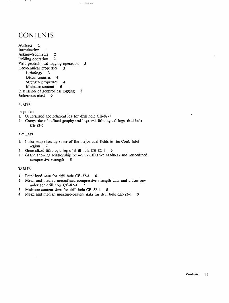
CONTENTS Abstract 1 Introduction 1 Acknowledgments 2 Drilling operation 2 Field geotechnical-logging operation 3 Geotechnical properties 3
Lithology 3 Discontinuities 4 Strength properites 4 Moisture content 5
Discussion of geophysical logging 5 References cited 9
PLATES
In pocket 1. Generalized geotechnical log for drill hole CE-82-1 2. Composite of refined geophysical logs and lithological logs, drill hole
CE-82-1
FIGURES
1. Index map showing some of the major coal fields in the Cook Inlet region 2
2. Generalized lithologic log of drill hole CE-82-1 3 3. Graph showing relationship between qualitative hardness and unconfined
compressive strength 5
TABLES
1. Point-load data for drill hole CE-82-1 6 2. Mean and median unconfined compressive strength data and anisotropy
index for drill hole CE-82-1 7 3. Moisture-content data for drill hole CE-82-1 8 4. Mean and median moisture-content data for drill hole CE-82-1 9
Contents III
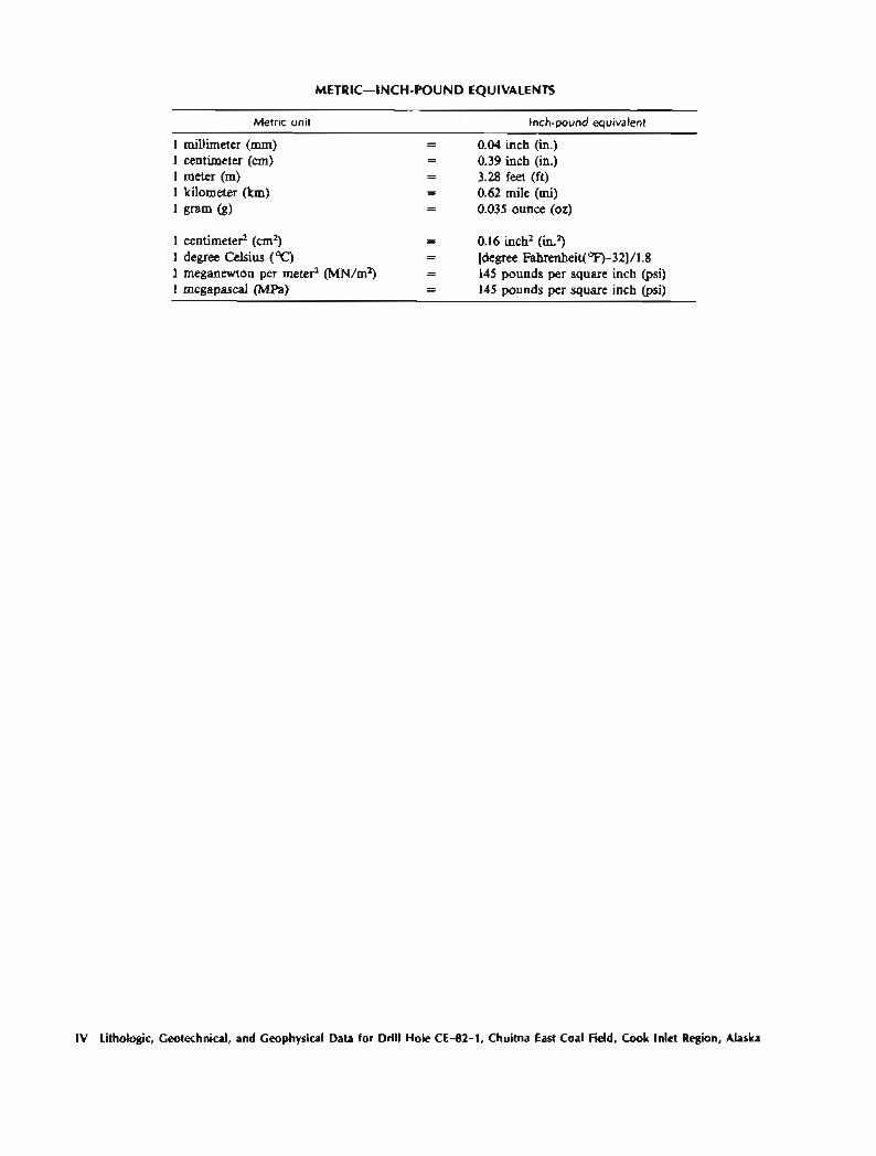
METRIC-INCH-POUND EQUIVALENTS
Metric unit Inch-pound equivalent
1 millimeter (mm) - - 0.04 inch (in.) 1 centimeter (cm) - - 0.39 inch (in.) 1 meter (m) - - 3.28 feet (ft) 1 kilometer (km) - - 0.62 mile (mi) 1 gram (g) - - 0.035 ounce (02)
1 centimeter2 (cm2) - 0.16 inch2 (in.2) 1 degree Celsius (OC) - - [degree Fahrenheit(OF)-32]/1.8 1 meganewton per meterZ (MN/m2) - - 145 pounds per square inch (psi) 1 megapascal (MPa) - - 145 pounds per square inch (psi)
IV Lithologic, Geotechnical, and Geophysical Data for Drill Hole CE-82-1, Chuitna East Coal Field, Cook Inlet Region, Alaska
Lithologic, Geotechnical, and Geophysical Data for Drill Hole CE-82-1, Chuitna East Coal Field, Cook Inlet Region, Alaska
By Jack K. Odum, Cynthia A. Gardner, Henry R. Schmoll, Lynn A. Yehle, and Larry L. Dearborn'
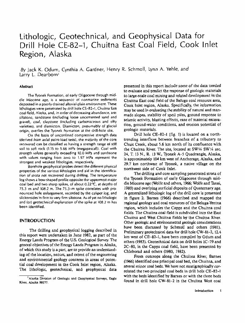
Abstract
The Tyonek Formation, of early Oligocene through mid- dle Miocene age, i s a sequence of nonmarine sediments deposited in a poorly drained alluvial-plain environment. These lithologies were penetrated by drill hole CE-82-1, Chuitna East coal field, Alaska, and, in order of decreasing abundance, are: siltstone, sandstone (including loose uncemented sand and gravel), coal, claystone (including carbonaceous and silty varieties), and diamicton. Diamicton, presumably of glacial origin, overlies the Tyonek Formation at the drill-hole site.
On the basis of unconfined compressive strength data (derived from axial point-load tests), the majority of the core recovered can be classified as having a strength range of stiff soil to soft rock (1.15 to 5.66 MPa (megapascal)). Coal with strength values generally exceeding 10.0 MPa and sandstone with values ranging from zero to 1.97 MPa represent the strongest and weakest lithologies, respectively.
Borehole geophysical probes detect the different physical properties of the various lithologies and aid in the identifica- tion of strata not recovered during drilling. The temperature log shows a bow-shaped profile opposite the uppermost major coal bed and two sharp spikes, of about 0.22OC, at depths of 75.3 m and 108.2 m. The 75.3-m spike correlates with pro- nounced hole enlargement, recorded by the caliper log, and slickensides in firm to very firm siltstone. As of yet no lithologic and (or) geotechnical explanation of the spike at 108.2 m has been identified.
l NTRODUCTION
The drilling and geophysical logging described in this report were undertaken in June 1982, as part of the Energy Lands Program of the U.S. Geological Survey. The general objectives of the Energy Lands Program in Alaska, of which this study is a part, are to provide an understand- ing of the location, nature, and extent of the engineering and environmental geology concerns in areas of poten- tial coal development in the Cook Inlet region, Alaska. The lithologic, geotechnical, and geophysical data - -
'Alaska Division of Geologic and Geophysical Surveys, Eagle River. Alaska 99577.
presented in this report include some of the data needed to evaluate and predict the response of geologic materials to large-scale coal mining and related development in the Chuitna East coal field of the Beluga coal resource area, Cook Inlet region, Alaska. Specifically, the information may be used in evaluating the stability of natural and man- made slopes, stability of spoil piles, ground response to seismic activity, blasting effects, ease of material excava- tion, ground-water conditions, and erosion potential of geologic materials.
Drill hole CE-82-1 (fig. 1) is located on a north- trending interfluve between branches of a tributary to Chuit Creek, about 5.6 km north of its confluence with the Chuitna River. The site, located at SW ?A SW ?4 sec. 24, T. 13 N., R. 13 W., Qonek A-5 Quadrangle, Alaska, is approximately 104 km west of Anchorage, Alaska, and 29.7 km northwest of Vonek, a native village on the northwest side of Cook Inlet.
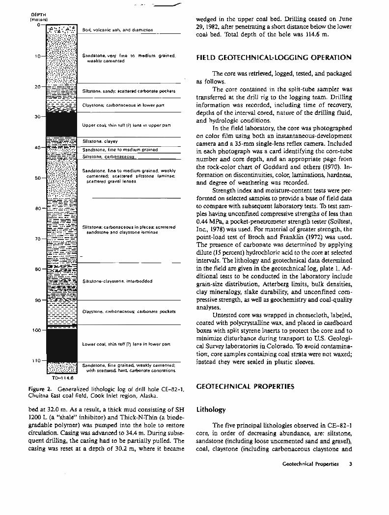
The drilling and core sampling penetrated strata of the Qonek Formation of early Oligocene through mid- dle Miocene age (Wolfe and others, 1966, Wolfe and Thai, 1980) and overlying surficial deposits of Quaternary age. A generalized lithologic log of the drill core is presented in figure 2. Barnes (1966) described and mapped the regional geology and coal resources of the Beluga-Yentna region, which includes the Capps and the Chuitna coal fields. The Chuitna coal field is subdivided into the East Chuitna and West Chuitna fields by the Chuitna River. Other geologic and environmental geologic considerations have been discussed by Schmoll and others (1981). Preliminary geotechnical data for drill hole CW-81-2, 12.4 km west of CE-82-1, have been compiled by Odum and others (1983). Geotechnical data on drill holes 1C-79 and 2C-80, in the Capps coal field, have been presented by Chleborad and others (1980, 1982).
From outcrops along the Chuitna River, Barnes (1%6) identified one principal coal bed, the Chuitna, and several minor coal beds. We have not stratigraphically cor- related the two principal coal beds in drill hole CE-82-1 with the beds identified by Barnes or with the three beds found in drill hole CW-81-2 in the Chuitna West coal
Introduction 1
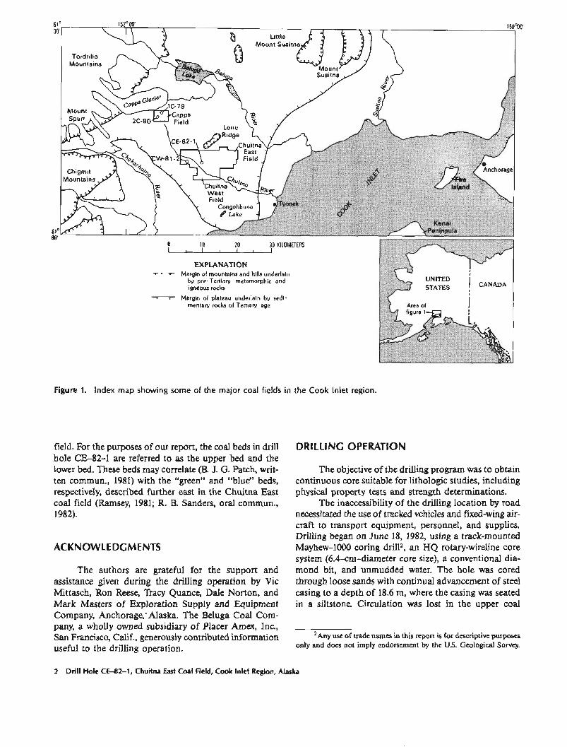
Figure 1. Index map showing some of the major coal fields in the Cook lnlet region.
field. For the purposes of our report, the coal beds in drill hole CE-82-1 are referred to as the upper bed and the lower bed. These beds may correlate (B. J. G. Patch, writ- ten commun., 1981) with the "green" and "blue" beds, respectively, described further east in the Chuitna East coal field (Ramsey, 1981; R. B. Sanders, oral commun., 1982).
ACKNOWLEDGMENTS
The authors are grateful for the support and assistance given during the drilling operation by Vic Mittasch, Ron Reese, Tracy Quance, Dale Norton, and Mark Masters of Exploration Supply and Equipment Company, Anchorage,' Alaska. The Beluga Coal Com- pany, a wholly owned subsidiary of Placer Amex, Inc, San Francisco, Calif., generously contributed information useful to the drilling operation.
DRILLING OPERATION
The objective of the drilling program was to obtain continuous core suitable for lithologic studies, including physical property tests and strength determinations.
The inaccessibility of the drilling location by road necessitated the use of tracked vehicles and fixed-wing air- craft to transport equipment, personnel, and supplies. Drilling began on June 18, 1982, using a track-mounted Mayhew-1000 coring drill2, an HQ rotary-wireline core system (6.4-cm-diameter core size), a conventional dia- mond bit, and unmudded water. The hole was cored through loose sands with continual advancement of steel casing to a depth of 18.6 m, where the casing was seated in a siltstone. Circulation was lost in the upper coal
' ~ n y use of trade names in this report is for descriptive purposes only and does not imply endorsement by the U.S. Geological Survey.
2 Drill Hole CE-82-1, Chuitna East Coal Field, Cook lnlet Region, Alaska
DEPTH (meters)
Siltstone; carbonaceous in places; scattered sandstone and claystone laminae
Siltstone-claystone, interbedded
Lower coal, thin tuff (?) lens in lower pan
Figure 2. Generalized lithologic log of drill hole CE-82-1, Chuitna East coal field, Cook Inlet region, Alaska.
bed at 32.0 m. As a result, a thick mud consisting of SH 1200 L (a "shale" inhibitor) and Thick-N-Thin (a biode- gradable polymer) was pumped into the hole to restore circulation. Casing was advanced to 34.4 m. During subse- quent drilling, the casing had to be partially pulled. The casing was reset at a depth of 30.2 m, where it became
wedged in the upper coal bed. Drilling ceased on June 29, 1982, after penetrating a short distance below the lower coal bed. Total depth of the hole was 114.6 m.
FIELD GEOTECHNICAL-LOGGING OPERATION
The core was retrieved, logged, tested, and packaged as follows.
The core contained in the split-tube sampler was transferred at the drill rig to the logging team. Drilling information was recorded, including time of recovery, depths of the interval cored, nature of the drilling fluid, and hydrologic conditions.
In the field laboratory, the core was photographed on color film using both an instantaneous-development camera and a 35-mm single-lens reflex camera. Included in each photograph was a card identifying the core-tube number and core depth, and an appropriate page from the rock-color chart of Goddard and others (1970). In- formation on discontinuities, color, laminations, hardness, and degree of weathering was recorded.
Strength index and moisture-content tests were per- formed on selected samples to provide a base of field data to compare with subsequent laboratory tests. To test sam- ples having unconfined compressive strengths of less than 0.44 MPa, a pocket-penetrometer strength tester (Soiltest, Inc., 1978) was used. For material of greater strength, the point-load test of Broch and Franklin (1972) was used. The presence of carbonate was determined by applying dilute (15 percent) hydrochloric acid to the core at selected intervals. The lithology and geotechnical data determined in the field are given in the geotechnical log, plate 1. Ad- ditional tests to be conducted in the laboratory include grain-size distribution, Atterberg limits, bulk densities, clay mineralogy, slake durability, and unconfined com- pressive strength, as well as geochemistry and coal-quality analyses.
Untested core was wrapped in cheesecloth, labeled, coated with polycrystalline wax, and placed in cardboard boxes with split styrene inserts to protect the core and to minimize disturbance during transport to U.S. Geologi- cal Survey laboratories in Colorado. To avoid contamina- tion, core samples containing coal strata were not waxed; instead they were sealed in plastic sleeves.
GEOTECHNICAL PROPERTIES
Lithology
The five principal lithologies observed in CE-82-1 core, in order of decreasing abundance, are: siltstone, sandstone (including loose uncemented sand and gravel), coal, claystone (including carbonaceous claystone and
Ceotechnical Properties 3
carbonaceous shale), and diarnicton. About 20 percent of the total core material was not recovered.
Siltstone makes up approximately 34 percent of the core. The thickest siltstone unit lies between 57.0 and 87.1 m, between the two thick coal beds. Laminae and beds of sandstone, loose sand, and claystone, ranging in thick- ness from a few millimeters to 0.49 m, occur throughout this large siltstone unit. Thin siltstone units are scattered throughout the cored section. These siltstones vary from sandy to clayey. Thin stringers of carbonaceous material and small inclusions of weakly carbonate cemented nodules are common throughout the siltstone.
Sandstone (including uncemented sand and gravel) forms approximately 31 percent of the total core. It ranges in texture from very fine to coarse grained and varies from poorly to well sorted. Noncemented to weakly cemented sandstone occurs in three principle units: (1) 3.0-19.0 m, (2) 44.0-56.0 m, and (3) 110.0-114.6 m. The two upper units, composed mainly of uncemented sand with gravel at their base, were poorly recovered. Approximately 60 percent of the core from each of the upper units was not recovered. Caving of the uppermost unit during the removal of cas- ing prevented completion of the geophysical logging. The lowermost unit (110.0-114.6 m), composed predominantly of fine- to medium-grained sand, ranges from very soft to very hard in consistency and was recovered without core loss. A very hard zone at 112.8 m is composed of a 0.3-m- thick carbonatecemented unit.
Coal, thought to be lignitic to subbituminous, con- stitutes about 17 percent of the material cored. N o thick coal beds were identified from the core: (1) an upper coal bed from 29.0 to 36.9 m and (2) a lower bed from 98.2 to 111.0 m. Both coal beds vary from massive to highly fractured, vertically and horizontally, and have thin part- ings near their tops-sandstone in the upper coal bed and claystone in the lower bed. Both coal beds also contain a tuffaceom(?) bed approximately 10.2 cm thick at 31.0 and 109.4 m, respectively.
Claystone, carbonaceous claystone, and carbona- ceous shale make up approximately 15 percent of the cored material and occur primarily as units immediately above each major coal bed at 26.0-28.0 and 91.0-98.0 m. Con- torted bedding zones were found within both units. This material, containing scattered laminae of siltstone, sand- stone, and coal, grades into coaly or carbonaceous horizons.
Diamicton, which represents about 3 percent of the cored material, extends from beneath the surface mantle of organic material and volcanic ash layers to a depth of 3.1 m. The diamicton is poorly sorted, with particles rang- ing in size from clay to boulders, and is presumably of glacial origin.
Discontinuities
We identified primarily three types of discontinuities in drill hole CE-82-1: (I) high-angle to near-vertical joints
(60' -85 9, (2) bedding-break separations, and (3) broken zones. The discontinuities in the core observed irnmediate- ly after recovery are plotted on plate 1 using a system modified from Rankilor (1974). It is difficult to distinguish between fractures induced during drilling and natural frac- tures, however, joints and bedding breaks plotted on plate 1 are believed to be natural.
All three types of discontinuities were found pri- marily in the two coal beds. Most fractures within the coal beds appeared to be fresh with no clear evidence of secon- dary mineralization or slickensides. The fresh nature of the fractures suggests that they may result in part from drilling and in part from the expansion of the coal along joint planes after removal from the confines of in-situ stress.
High-angle fractures and bedding-break separations were noted in the other lithologies, but were less frequent. However, slickensides wKe noted along many of the frac- tures in the claystones and clayey siltstones. In addition, offsets of 2.1-3.1 cm in the siltstone bedding were noted at 77.6 cm and in the interval from 89.5 to 89.73 m; sug- gesting some minor faulting, possibly in response to over- burden loading.
Strength Properties
Strength indices were conducted usually within a half hour of core extraction; thus, the samples are believed to have been at or near their natural moisture contents at the time of testing. Materials with strength values beyond the limit of the pocket penetrometer (0.44 MPa) were tested in the field using the point-load method of Broch and Franklin (1972). The point-load method is designed to test the core samples both diametrally (load applied parallel to the bedding plane) and axially (load applied perpendicular to the bedding plane). Resultant strength values, I,, were "corrected" to a reference diameter (I, (50)) of 5.0 cm, and the approximate uncon- fined compressive strength (I, (50) x 24) was calculated by multiplying the reference diameter value by an em- pirically determined coefficient of 24. The method was developed for horizontally laid strata; bedding planes from the CE-82-1 core dip from 5Oto 20' with respect to the horizontal. Comparison of these results with strength values calculated on nearby, near-horizontal strata of similar material (Chleborad and others, 1980, 1982) shows little difference in the ranges of strength values; thus, the results reported here are believed to be valid. However, the degree of dip made it difficult to ob- tain through-breaks on the axial tests; axial values may be low because failure would often occur as slippage along bedding planes.
Sandstone, loose sand, and gravel all tested within the range of the pocket penetrometer. These values, shown in plate 1, are excluded from the following discussion.
4 Drill Hole CE-82-1, Chuitna East Coal Field, Cook Inlet Region, Alaska
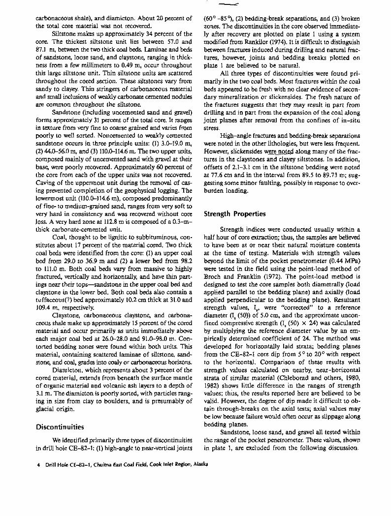
Approximate unconfined compressive strength in- dices for all lithologies ranged from 0.96 to 11.3 MPa for diametral tests, and from 1.2 to 11.3 MPa for axial tests. The mean-strength index values for the lithologies range from a stiff soil to a soft rock when compared to a relative scale of soiI and rock "hardness" devised by Jennings and Robertson (1969; fig. 3). The prevalence of low-strength values indicates that the material can be easily excavated. However, the low values and the interbedded nature of hard and soft layers also indicate a potential for erosion and for cut-slope stability problems, if conditions are not adequately evaluated in development plans.
Point-load test data are presented as a function of depth in table 1. Mean and median approximate uncon- fined compressive strength indices determined from diametral and axial tests, and a strength anisotropy in- dex (I, (50), Broch and Franklin, 1972) for the lithologies are given in table 2. The anisotropy index (I, (50)) is defined as the ratio of the median strength in the strongest direction to the median strength in the weakest direction (Broch and Franklin, 1972). An anisotropy index of 1 in- dicates that the material tested is essentially isotropic; greater than 1 indicates anistropy, with the axial strength being greater than the diametral strength.
The anisotropy indices (table 2) listed for the various lithologies from drill hole CE-82-1 suggest that the materials, with the exception of carbonaceous shale, are isotropic to slightly anisotropic Siltstone, clayey siltstone, claystone, and carbonacous claystone appear slightly stronger parallel to the bedding direction than in the ax- ial direction; difficulties in obtaining clean through-breaks
Range of strength test values from field tests on samples from drill hole CE-82-1
r-7 I I I I
I
Very soh soil---- I H I I
i I I
Soft soil------ I I Firm soil------I t-1 i I I Stiff soil------
I
Very stiff soil---- I I I I I
Very soft rock---
Soft rock-----
Hard rock-----
Very hard rock---I I I
Very very hard rock- 1 I I !
H Range of strength test values obtained by various workers
Figure 3. Relationship between qualitative hardness and un- confined compressive strength. (Modified from Jennings and Robertson, 1969.)
in the axial tests may account for the lower strength values in the axial direction. Coal appears only slightly stronger perpendicular to the bedding than parallel to it. High- angle to near-vertical jointing in the coal has probably weakened the overall strength of the coal in the axial clirec- tion. Carbonaceous shale appears to be highly anisotropic; the fissile nature of the shale accounts for its weakness along bedding planes.
Moisture Content
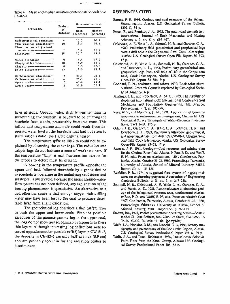
Moisture-content measurements were taken at in- tervals of approximately 0.5 m or at changes in lithology. Samples, weighing 15-30 g, were dried for about 4 hours in an oven at 105OC, and then weighed again to deter- mine the moisture loss. Moisture-content data as a func- tion of depth are presented in table 3. Mean and median moisture-content data in percent dry weight, and the number of samples tested for the various lithologies, are listed in table 4.
Although some lithologies were represented by on- ly a few samples, it was felt that combining them into fewer lithologic groups would be misleading. Generally, the moisture-content values for the lithologies fall within an acceptable range. Excluding the coal, carbonaceous claystone and shale had the highest moisture-content values. Generally, moisture-content values are higher in carbonaceous materials and in coarse or well-sorted materials and lower in poorly sorted and fine-grained materials. Coal moisture contents are not meant to be definitive values for the ranking of coal, rather they are a first approximation. Their high values may be due to the drilling process. The higher moisture content for the upper coal with respect to the lower coal may reflect the more broken nature of the upper coal or an actual dif- ference in composition.
DISCUSSION OF GEOPHYSICAL LOGGING
A suite of five borehole geophysical logs (pl. 2) was recorded for drill hole CE-82-1, starting about 15 hours after drilling ended. A fluid-temperature log was recorded first, followed in order by natural gamma, gamma- gamma, neutron, and caliper logs. The same Well Recon- naissance Geologger was used as in 1979-81 to supple- ment drill-hole data (Chleborad and others, 1980, 1982; Odum and others, 1983, respectively). Because drilling procedures and lithologies were similar to those of previous drill holes in the Beluga coal fields, log responses generally showed the same magnitudes of deflection.
One notable difference (disappointment) between CE-82-1 and the three drill holes logged in prior years was the natural filling of most the hole prior to the com- pletion of logging. After five logging runs, the casing was
Discussion of Geophysical Logging 5
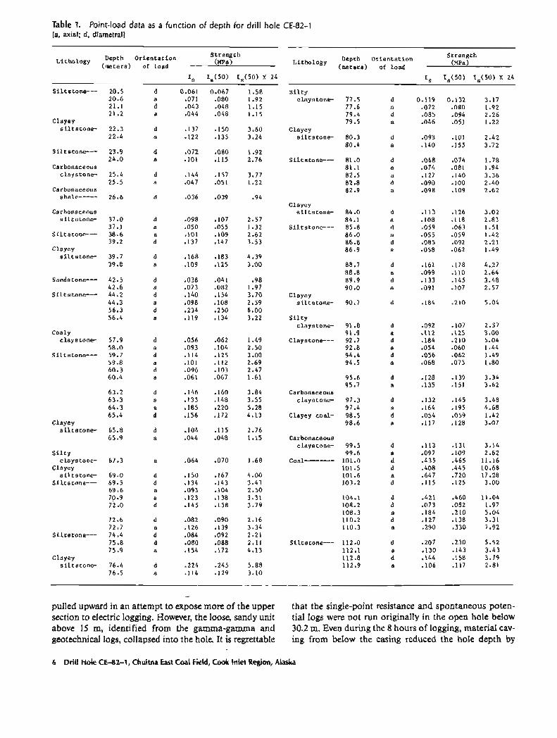
Table 1. Point-load data as a function of depth for drill hole CE-82-1 [a, axial; d, diametral]
Lithology Depth Or ien ta t ion S t reng th Lithology Depth Or ien ta t ion S t reng th
(meters) of load (MPa) (meters) of load (MPa)
Is Is(50) Is(50) X 24
Si l ts tone--- 20.5 d 0.061 0.067 1.58 20.6 a -071 .080 1.92 21.1 d -043 -048 1.15 21.2 a -044 .048 1.15
Clayey s i l t s t o n e - 22.3 d .I37 .I50 3.60
22.4 a .I22 .I35 3.24
S i l t stone---
Carbonaceous c l a y s t o n e
Carbonaceous shale-----
Carbonaceous s i l t s t o n e -
Clayey s i l t s t o n e -
Coaly claystone-
S i l t stone---
Clayey s i l t s t o n e -
S i l t y claystone-
Clayey s i l t s t o n e -
Siltstone---
Clayey s i l t s t o n e -
Is 19(50) I s (50) X 24
S i l t y claystone- 77.5 d 0.119 0.132 3.17
77.6 a .072 .080 1.92 79.4 d .085 .094 2.26 79.5 a .046 .051 1.22
Clayey s i l t s t o n e - 80.3 d .093 . lo1 2.42
Clayey s i l t s t o n e
Clayey s i l t s t o n e -
S i l t y claystone-
Claystone---
Carbonaceous claystone-
Clayey coal-
Carbonaceous claystone-
- - - - - - - -
- pulled upward in an attempt to expose more of the upper that the single-point resistance and spontaneous poten- section to electric logging. However, the loose, sandy unit tial logs were not run originally in the open hole below above 15 m, identified from the gamma-gamma and 30.2 m. Even during the 8 hours of logging, material cav- geotechnical logs, collapsed into the hole. It is regrettable ing from below the casing reduced the hole depth by
6 Drill Hole CE-82-1, Chuitna East Coal Field, Cook Inlet Region, Alaska
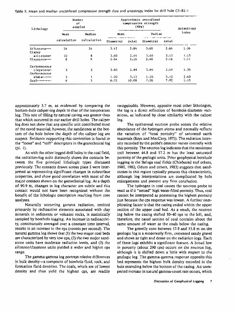
Table 2. Mean and median unconfined compressive strength data and anisotropy index for drill hole CE-82-1
Number Approximate unconfined of
L i tho logy samples
compressive s t r e n g t h (MPa) Anisotropy
Mean Median Me an Median index
c a l c u l a t i o n c a l c u l a t i o n Diametral Axial Diametral Axial
Sil tstone--- 24 24 3.12 2.64 3.60 2.64 1.36 Clayey
s i l t s t o n e - 10 8 3.60 2.64 3.60 3.12 1.15 Claystone--- 8 9 2.64 2.16 2.40 2.16 1.11
Carbonaceous c l a y s tone- 3 3 3.60 2.88 3.60 2.64 1.36
Carbonaceous s ha1 e----- 2 1 1.20 3.12 1.20 3.12 2.60
Coal -------- 6 3 6.72 10.08 7.20 7.92 1.10
approximately 3.7 m, as evidenced by comparing the bottom-hole caliper-log depth to that of the temperature log. This rate of filling by natural caving was greater than that which occurred in our earlier drill holes. The caliper log does not show that any specific unit contributed most of the caved material; however, the sandstones at the bot- tom of the hole below the depth of the caliper log are suspect. Evidence supporting this contention is found in the "loose" and "soft" descriptors in the geotechnical log (PI- 1).
As with the other logged drill holes in the coal field, the radiation-log suite distinctly shows the contacts be- tween the five principal lithologic types discussed previously. The contacts drawn across plate 2 were inter- preted as representing significant changes in subsurface properties, and show good correlation with most of the major contacts shown on the geotechnical log. At a depth of 90.9 m, changes in log character are subtle and this contact would not have been recognized without the benefit of the lithologic description resulting from core analyses.
Naturally occurring gamma radiation, emitted primarily by radioactive elements associated with clay minerals in sediments or volcanic rocks, is statistically sampled by borehole logging. An increase in radioactivi- ty, continuously averaged over a constant time interval, results in an increase in the cps (counts per second). The natural gamma log shows that (1) the two major coal beds are characterized by very low cps, (2) the two major sand- stone units have moderate radiation levels, and (3) the siltstone/claystone units yielded a wider and higher cps range.
The gamma-gamma log portrays relative differences in bulk density-a composite of borehole fluid, rock, and formation fluid densities. The coals, which are of lowest density and thus yield the highest cps, are readily
recognizable. However, opposite most other lithologies, the log is a direct reflection of borehole-diameter vari- ations, as indicated by close similarity with the caliper log.
The epithermal neutron probe senses the relative abundance of the hydrogen atoms and normally reflects the variation of "total porosity" of saturated earth materials (Keys and MacCary, 1971). The radiation inten- sity recorded by the probe's detector varies inversely with this porosity. The neutron log indicates that the sandstone unit between 44.8 and 57.2 m has the least saturated porosity of the geologic units. Prior geophysical borehole logging in the Beluga coal fields (Chleborad and others, 1980, 1982; Odum and others, 1983) suggests that sand- stones in this region typically possess this characteristic, although log interpretations are complicated by hole enlargements and prevent any firm conclusion.
The hydrogen in coal causes the neutron probe to react as if it "sensed" high water-filled porosity. Thus, coal cannot be interpreted as possessing the highest porosity just because the cps response was lowest. A further com- plicating factor is that the casing ended within the upper section of the upper coal bed. As a result, the neutron log below the casing shifted 30-40 cps to the left, and, therefore, the cased section of coal contains about the same amount of water as the coals below the casing.
The gravelly zone between 52.9 and 55.8 m on the geologic log is a moderately firm, cemented sandy gravel and shows as tight and dense on the radiation logs. Each of these logs exhibits a significant feature. A broad low in porosity (about 290 cps) occurs on the neutron log, although it is shifted down a little with respect to the geologic log. The gamma-gamma response opposite this bed represents the highest bulk density recorded in the hole extending below the bottom of the casing. An unex- pected increase in natural gamma-count rate occurs, which
Discussion of Geophysical Logging 7
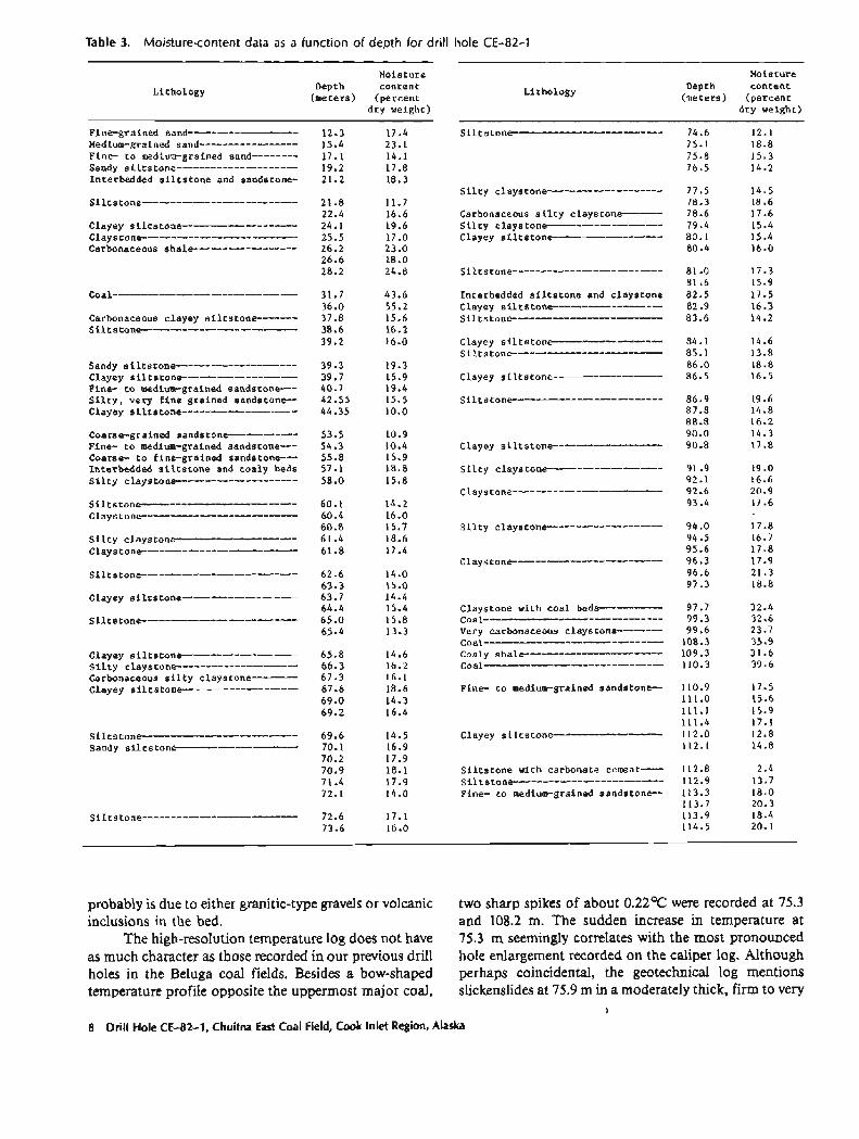
Table 3. Moisture-content data as a function of depth for drill hole CE-82-1
Moisture Moisture
Li thology Depth content (meters) (percent
Li thology Depth con ten t
(meters) ( ~ e r c e n t - . dry weight)
siltstone------------------------- 74.6 12.1 75.1 18.8 75.8 15.3 76.5 14.2
dry weight)
~ i ~ ~ - ~ ~ ~ i ~ ~ d sand------------------- 12.3 17.4 Medium-grained sand----------------- 15.4 23.1 Fine- t o medium-grained sand-------- 17.1 14.1 sandy siltstone--------------------- 19.2 17.8 Interbedded s i l t s t o n e and sandstone- 21.2 18.3
silty claystone-------------------- 77.5 14.5 78.3 18.6
Carbonaceous s i l t y claystone------- 78.6 17.6 s i l t y claystone------------------- 79.4 15.4 clayey siltstone------------------- 80.1 15.4
80.4 16.0
siltstone--------------------------- 21.8 11.7 22.4 16.6
clayey siltstone-------------------- 24.1 19.6 claystone--------------------------- 25.5 17.0 Carbonaceous shale------------------ 26.2 23.0
26.6 18.0 28.2 24.8 siltstone-------------------------- 81.0 17.3
81 .6 15.9 Interbedded s i l t s t o n e and c lays tone 82.5 17.5 clayey siltstone------------------- 82.9 16.3 siltstone-------------------------- 83.6 14.2
36.0 55.2 Carbonaceous clayey siltstone------- 37.8 15.6
sandy siltstone--------------------- 39.3 19.3 clayey siltstone-------------------- 39.7 15.9 Fine- t o medium-grained sandstone--- 40.7 19.4 S i l t v . verv f i n e a ra ined sandstone-- 42.55 15.5
Coarse-grained sandstone------------ Fine- t o medium-grained sandstone--- Coarse- t o f ine-grained sandstone--- Interbedded s i l t s t o n e and coaly beds S i l t Y claystone---------------------
Claystone with coa l beds----------- Coal------------------------------- Very carbonaceous claystone-------- coax----------------------------- Coaly shale------------------------ Coal-------------------------------
Clayey siltstone------------------- S i l t , , claystone--------------------- Carbonaceous s i l t y claystone-------- Clayey siltstone-------------------- Fine- t o medium-grained sandstone--
S i l t s t o n e with carbonate cement---- Siltstone-------------------------- Fine- t o medium-grained s a n d s t o n e -
probably is due to either granitic-type gravels or volcanic two sharp spikes of about 0.22T were recorded at 75.3 inclusions in the bed. and 108.2 m. The sudden increase in temperature at
The high-resolution temperature log does not have 75.3 m seemingly correlates with the most pronounced as much character as those recorded in our previous drill hole enlargement recorded on the caliper log. Although holes in the Beluga coal fields. Besides a bow-shaped perhaps coincidental, the geotechnical log mentions temperature profile opposite the uppermost major coal, slickenslides at 75.9 m in a moderately thick, firm to very
I
8 Drill Hole CE-82-1, Chuitna East Coal Field, Cook Inlet Region, Alaska
REFERENCES CITED Table 4. Mean and median moisture-content data for drill hole CE-82-1
Moisture content Number
Li tho logy of Mean Median
(percent) (percent)
Medium-grained sandstone Fine-grained s a n d s t o n e - Fine- t o coarse-grained
sandstone------------ Siltstone--------------
Sandy siltstone--------- Clayey siltstone------- Claystone--------------- S i l t y claystone---------
Carbonaceous claystone-- Carbonaceous shale------ upper coal -------------- Lower coal--------------
firm siltstone. Ground water, slightly warmer than its surrounding environment, is believed to be entering the borehole from a thin, presumably fractured zone. This inflow and temperature anomaly could result from de- pressed water level in the borehole that had not risen to stabilization (static level) after drilling ceased.
The temperature spike at 108.2 m could not be ex- plained by observing the other logs. The radiation and caliper logs do not indicate a zone of weakness here. If the temperature "blip" is real, fractures too narrow for the probes to detect must be present.
A bowing in the temperature profile opposite the upper coal bed, followed downhole by a gentle decline in borehole temperature in the underlying sandstones and siltstones, is observable. Because the area's ground-water- flow system has not been defined, any explanation of the bowing phenomenon is speculative. An alternative to a hydrothermal cause is that enough oxygen-rich drilling water may have been lost to the coal to produce detec- table heat from slight oxidation.
The geotechnical log describes a thin tuff(?) layer in both the upper and lower coals. With the possible exception of the gamma-gamma log in the upper coal, the logs do not show any recognizable responses to these thin layers. Although interesting log deflections were re- corded opposite another possible tuff(?) layer in CW-81-2, the deposits in CE-82-1 are only half as thick (0.9 cm) and are probably too thin for the radiation probes to discriminate,
Barnes, F. F., 1966, Geology and coal resources of the Beluga- Yentna region, Alaska: U.S. Geological Survey Bulletin 1202-C, 54 p.
Broch, E., and Franklin, J. A., 1972, The point-load strength test: International Journal of Rock Mechanics and Mining Sciences, v. 9, no. 6, p. 669-697.
Chleborad, A. F., Yehle, L. A., Schrnoll, H. R., and Gardner, C. A., 1980, Preliminary field geotechnical and geophysical logs from a drill hole in the Capps coal field, Cook Inlet region, Alaska. U.S. Geological Survey Open-Fie Report 80-393, 17 p.
Chleborad, A. E, Yehle, L. A., Schmoll, H. R., Gardner, C. A., and Dearborn, L. L., 1982, Preliminary geotechnical and geophysical logs from drill hole 2C-80 in the Capps coal field, Cook Inlet region, Alaska: U.S. Geological Survey Open-File Report 82-884, 9 p.
Goddard, E. N., chairman, and others, 1970, Rock-color chart: National Research Council; reprinted by Geological Socie- ty of America, 6 p.
Jennings, J. E., and Robertson, A. M. G., 1969, The stability of slopes cut into natural rock: International Conference Soil Mechanics and Foundation Engineering, 7th, Mexico, Proceedings, v. 2, p. 585-590.
Keys, W. S., and MacCary, L. M., 1971, Application of borehole geophysics to water-resources investigations, Chapter El: U.S. Geological Swey Echniques of Water-Resources Investiga- tions, TWI 2-El, 126 p.
Odum, J. K., Gardner, C. A., Yehle, L. A., Schmoll, H. R., and Dearborn, L. L., 1983, Preliminary lithologic, geotechnical, and geophysical data fmm drill hole CW-81-2, Chuitna West wal field, Cook Inlet region, Alaska: U.S. Geological Survey Open-File Report 83-78, 12 p.
Ramsey, J. P., 1981, Geology-Coal resources and mining plan for the Chuitna River field, Alaska, in Rao, P. D., and Wolff, E. N., eds., Focus on Alaska's coal "80': Conference, Fair- banks, Alaska, October 21-23, 1980, Pr-gs: Fairbanks, University of Alaska, School of Mineral Industry, MIRL Report SO, p. 111-121.
Rankilor, P. R., 1974, A suggested field system of logging rock wres for engineering purposes: Association of Engineering Geologists Bulletin, v. 11, no. 3, p. 247-258.
Schmoll, H. R., Chleborad, A. F., Yehle, L. A., Gardner, C. A., and Pasch, A. D., 1981, Reconnaissance engineering geol- ogy of the Beluga coal resource area, southcentral Alaska, in Rao, F? D., and Wolff, E. N., eds., Focus on Alaska's Coal "80': Conference, Fairbanks, Alaska, October 21-23, 1980, Proceedings: Fairbanks, University of Alaska, School of Mineral Industry, MIRL Report 50, p. 92-110.
Sodtest, Inc, 1978, Pocket penetrometer operating details-Soitest model CL-700: Soiltest, Inc, 2205 Lee Street, Evanston, 11- linois, 60202, Bulletin 151-64, [pamphlet].
Wolfe, J. A, Hop& D. M., and Leopold, E. 8,1966, lbtiary stra- tigraphy and paleobotany of the Cook Inlet Region, Alaska: U.S. Geological Survey Professional Paper 398-A, 29 p.
Wolfe, J. A., and Ttmai, mshimasa, 1980, The Miocene Seldovia Point Flora from the Kenai Group, Alaska: U.S. Geologi- cal Survey Professional Paper 105, 52 p.
References Cited 9