Embed Size (px)
Citation preview

Dr. Stefan WenauSenior Scientist [email protected]
Advanced methods for geophysical and geotechnical soil investigation
for the offshore wind industry
Virtual Wind II – Current challenges for offshore wind energy in the North Sea08.07.2020

Clare et al., 2012; Winter et al., 2017
Offshore windfarm site characterization
• Hydrographic/UxO survey• Multibeam sonar bathymetry• Sidescan Sonar • Magnetics
• Geophysical site characterization• Subbottom profiler• Single-/Multichannel Seismics• Geological model• Geological hazard identification (boulders, faults)
• Geotechnical site characterization• Cone Penetration Tests (CPT)• Bore holes• Soil model
Integrated soil model Foundation design

Multichannel seismic principles
• Imaging of impedance constrasts• Impedance = seismic velocity x density
• Excellent imaging of geological structures• Quantitative approaches to extract
geotechnical properties

Multichannel Seismic Data Acquisition
• Seismic signal source• Seismic data recording• Positioning of equipment
• Survey vessel• ~5 kn survey speed• Profile spacing e.g. 100 m
2D acquisition layout 3D acquisition layout

MCS equipment considerations – signal source
Subbottomprofiler
Boomer
Sparker
Air gun(Micro-GI-Gun)
Signal penetrationResolutionFrequency content
~4000 Hz
1000-2000 kHz
300-2000 kHz
100-600 Hz
cm-dm
dm-m
dm-m
m
10-20 m
~50 m
~200 m
>200 m

MCS equipment considerations – recording
• Multichannel approach• Increased spatial sampling along profile• Significantly larger processing capabilities (velocity analysis, stacking)• Optimized offsets for imaging target (complex geology) Number of hydrophones
Receiver spacing
Hydrophone groupsvs.
Single hydrophones
Offset
Exploration-scalevs.
shallow waterUHR
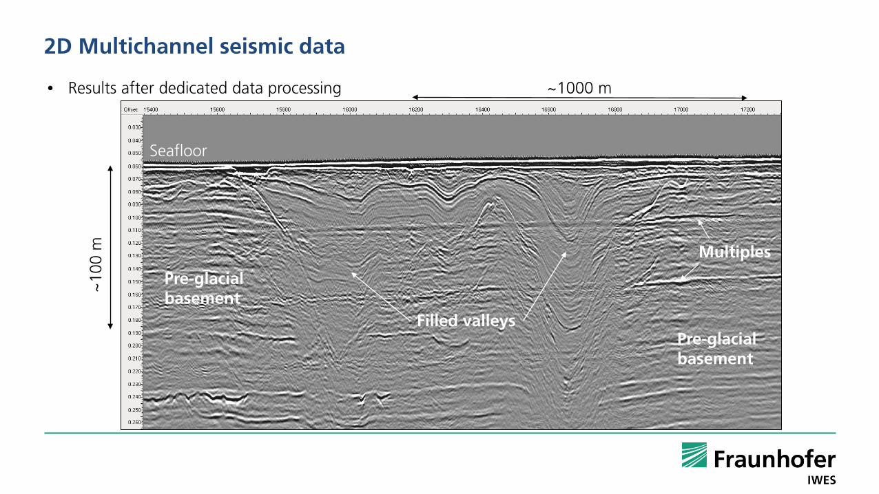
2D Multichannel seismic data
~10
0 m
~1000 m• Results after dedicated data processing
Seafloor
Multiples
Filled valleys
Pre-glacialbasement
Pre-glacialbasement

2D Multichannel seismic data
• Interpretation of seismic units
~10
0 m
~1000 m Interpolated horizon surface
Valleys
Pre-glacialbasement
Seafloor

3D Multichannel seismic data
• Full volume seismic data• No interpolation between profiles• Clear imaging of complex
structures• Valley fills• Faults
Time slice
Inline
X-line
Glacial tunnelvalleys

3D seismic data - attribute studies
SpectraldecompositionRGB
CablesCables
Glacial tunnel valleys
• Extraction of detailed information on structures and properties of geological features

Geotechnical site characterization
• Locations identified after geophysical survey
• Cone Penetration Test (CPT)• Derivation of geotechnical parameters from friction measurements
• Bore holes• Samples for geotechnical testing
• Measurements at representative locations within wind farm area• Characterization of identified geological units• Soil model
• Measurements at every WTG location• Characterization of detailed soil profile for foundation design

Integration of geophysical and geotechnical data
M. Vardy, 2020. GeoExPro 17, 2
• Geotechnical point information limits flexibility in wind farm layout
Integrated soil model• Interpolation of geotechnical parameters supported
by geophysical data over full wind farm• Synthetic CPT
• Seismic attribute studies• Transfer information from geophysical data into the soil model
• Use machine learning to find geotechnical soil profiles based on seismic data and neighboring CPT
• Seismic inversion approaches to directly obtain parameters from seismic data, using existing geotechnical logs for calibration
• Geotechnical soil characterization at WTG location without actual geotechnical measurement

Hazards – boulder occurrence
• Widespread occurrence in northern Europe• Glacial till deposits• Variable sizes (< 1 m – 10 m)
Huuse and Lykke-Andersen, 2000
Rügen chalk cliffs
Baltic Sea glacial till
Holeyman et al., 2015

Conventional boulder mapping - diffraction mapping in seismic data
North Sea stacked seismic section
• SBP show insufficient signal penetration & coverage• Simple diffraction mapping in 2D seismic/acoustic data
• Pre-stack data• Localization ambiguities
Timeslice 3D GPR Stack volume
Grasmueck et al., 2012
Seafloor
Multiple
Diffractions

Existing concepts for sub-seafloor object detection
Guigné 2013; PanGeo Subsea Inc.Gutowski et al., 2008
3D GeoChirp• Near-surface 3D object detection
PanGeo Acoustic Corer• Seabed system

Dedicated diffraction imaging for boulder detection
• Point diffraction imaging using specialized seismic acquisition system
• Small-scale objects produce diffractions
• Separation of diffracted and reflected wave field
• Increased resolution for object sizes > 0.5 m to ~100 mbsf
• Synthetic aperture processing
• Fit-for-purpose risk assessment for WTG foundation planning
• Secondary high-resolution 2D/3D site survey data

Manta Ray diffraction imaging
• Processing results in 3D diffraction amplitude volume• Resolution parameters dependent on acquisition strategy• Adaptable to different object sizes & depths
• Vessel-based tow-frame concept• Using standard seismic sources• WTG-location survey or full field• Sea trials 2018/19• First commercial survey 2019
Modelling results

Manta Ray - boulder detection results
Statistical analysis of diffraction amplitudevolumes
Integration of diffraction imaging andstratigraphic interpretation for targetidentification and risk mapping