Embed Size (px)
Citation preview
Liquid Fuel Burners
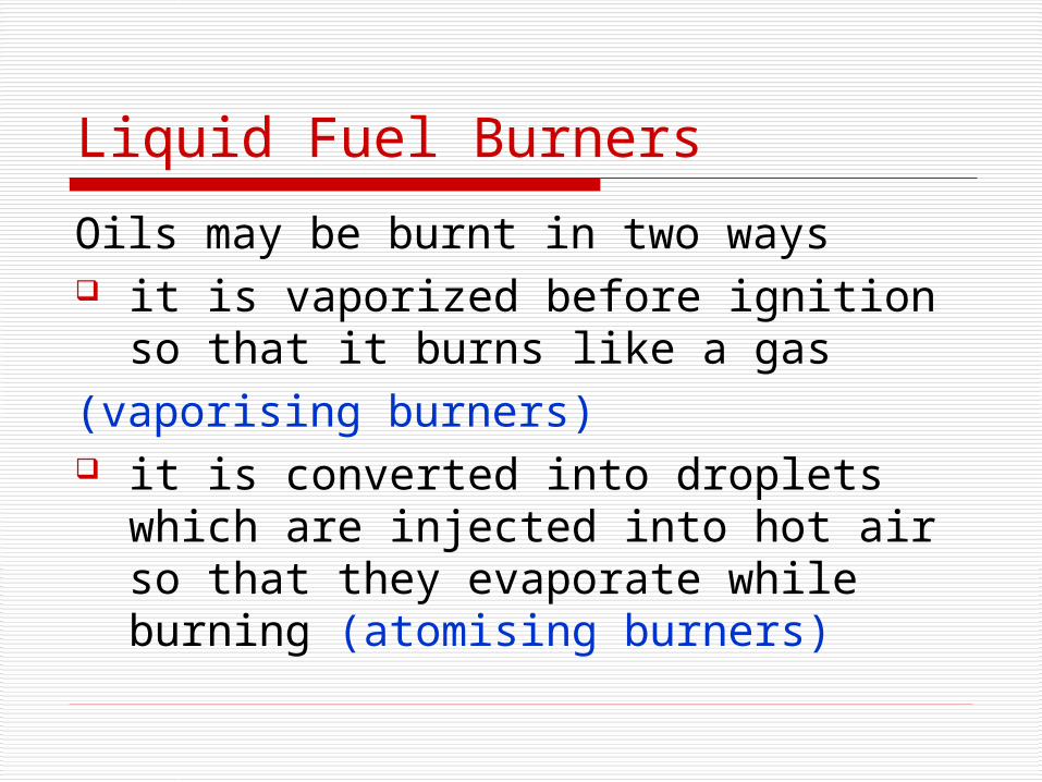
Oils may be burnt in two ways it is vaporized before ignition so that
it burns like a gas(vaporising burners) it is converted into droplets which are
injected into hot air so that they evaporate while burning (atomising burners)
Liquid Fuel Burners
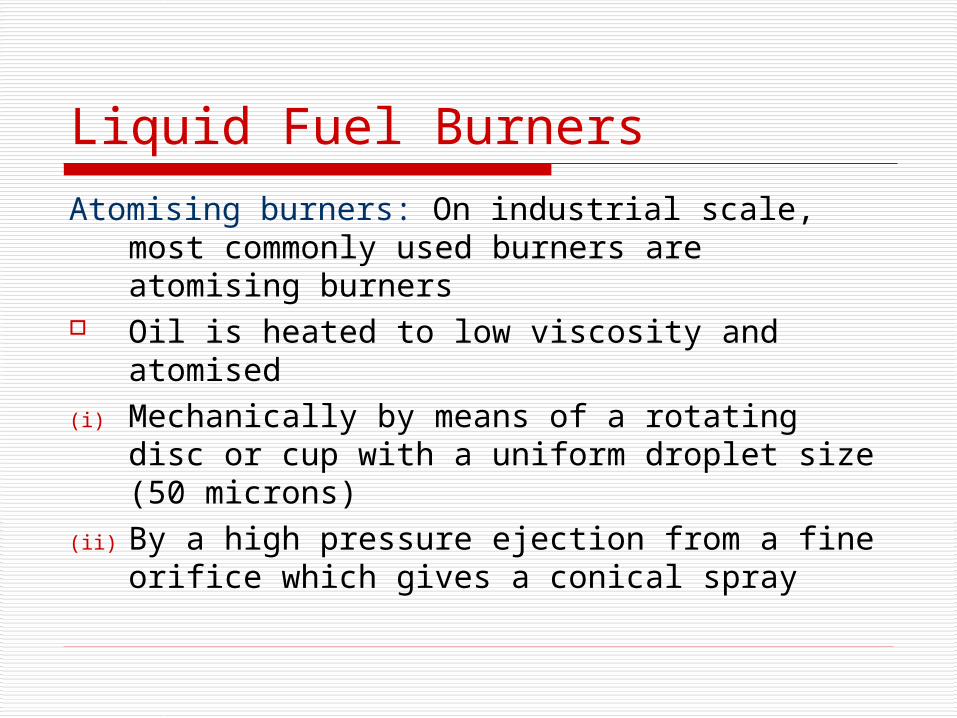
Atomising burners: On industrial scale, most commonly used burners are atomising burners
Oil is heated to low viscosity and atomised(i) Mechanically by means of a rotating disc
or cup with a uniform droplet size (50 microns)
(ii) By a high pressure ejection from a fine orifice which gives a conical spray
Types of Atomising Oil Burners
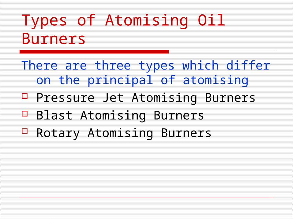
There are three types which differ on the principal of atomising
Pressure Jet Atomising Burners Blast Atomising Burners Rotary Atomising Burners
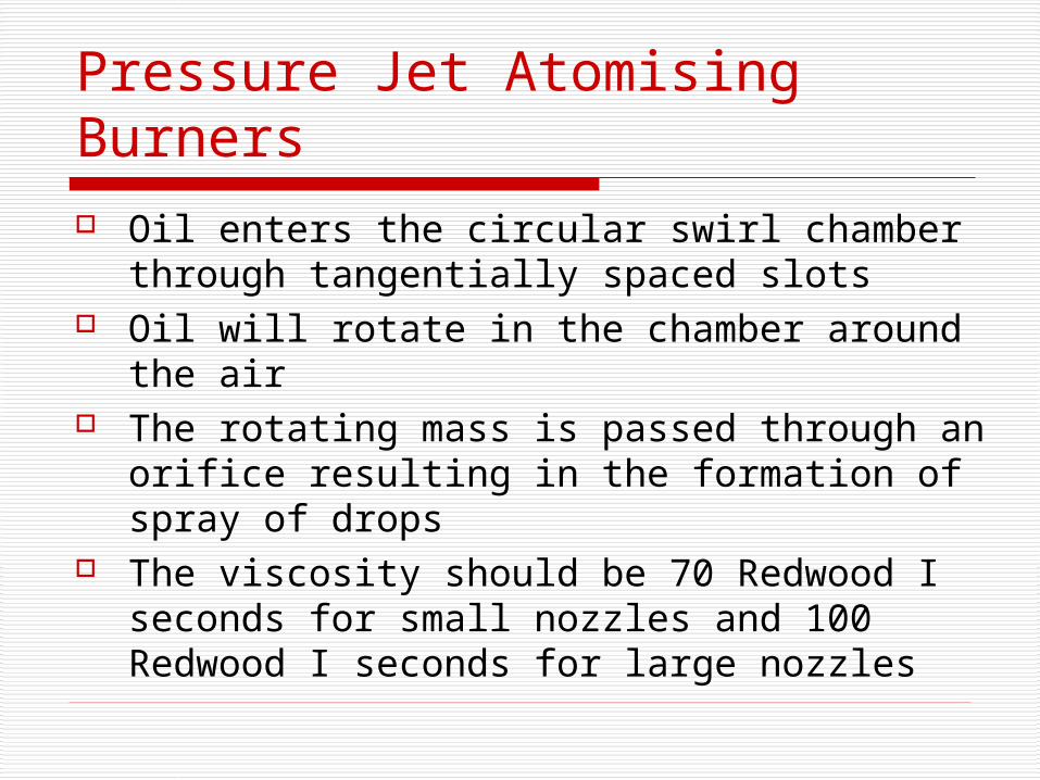
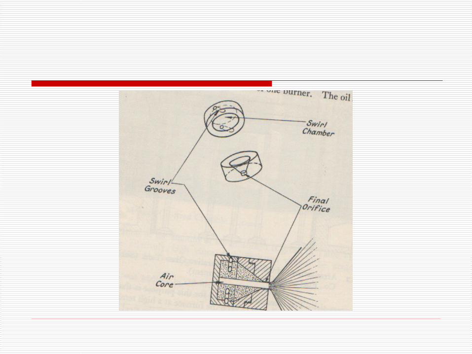
Pressure Jet Atomising Burners Oil enters the circular swirl chamber through
tangentially spaced slots Oil will rotate in the chamber around the air The rotating mass is passed through an orifice
resulting in the formation of spray of drops The viscosity should be 70 Redwood I seconds
for small nozzles and 100 Redwood I seconds for large nozzles
These burners have low operating cost and most widely used
These type of burners have limited turndown ratio
Turndown ratio can be increased by design modifications e.g. by increasing the number of tangential slots
Blast Atomising Burners
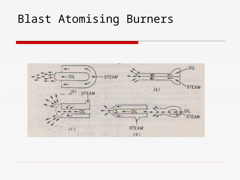
These burners use air or steam to atomize the oil
Oil flow through a central tube at a controlled rate mixed with mixed with air as it emerges from the tube
Depending upon the pressure they may be classified as Low pressure, Medium pressure or high pressure
Depending upon the mixing system they may be classified as inside-mix type or outside-mix type
Blast Atomising Burners
High pressure burners have high turndown ratio (10:1)
Inside-mix type commonly provide more eficiency
Blast Atomising Burners
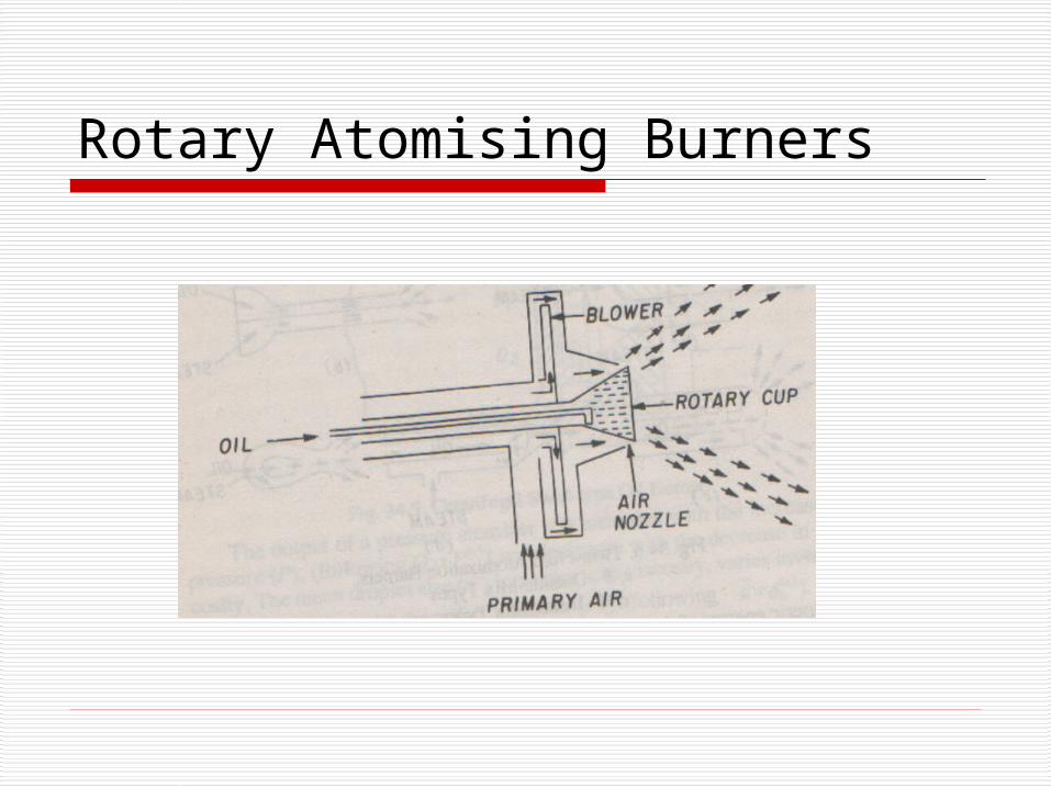
Rotary Atomising Burners These burners have a centeral stationary fuel line which
delivers the oil to the inner surface of rotating hollow cup The cup is rotated at 3600- 10,000 rpm Centrifugal force causes the oil to flow towards the brim of
the cup in the form of thin film which disintegrates into small droplets
A fan attached to the rotating shaft provides primary air These burners can be used for more viscous fuels Low viscosity may cause the oil to slip within the cup
resulting in low atomizing efficiency
These burners can have high turn down ratio but low capacity
Rotary Atomising Burners
Adiabatic Flame Temperature
For adiabatic flame temperature following assumptions are made
No heat loss to the surroundings Combustion is complete No thermal dissociation A reference/datum temperature is
selected
Adiabatic Flame Temperature
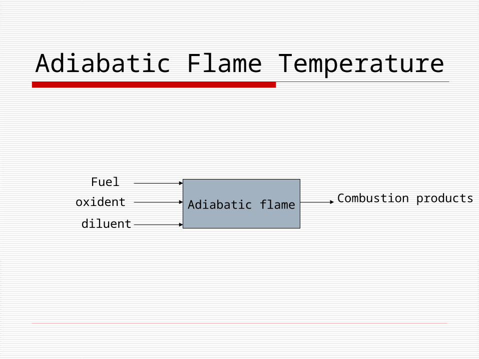
Adiabatic flame
Fuel
oxident
diluent
Combustion products
Adiabatic Flame Temperature
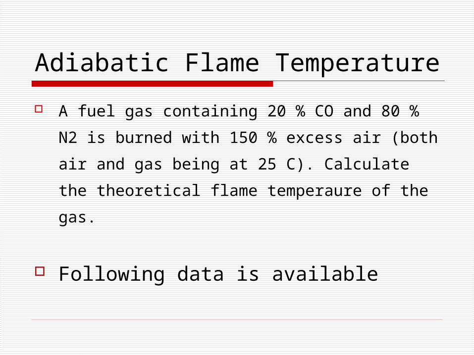
A fuel gas containing 20 % CO and 80 % N2 is
burned with 150 % excess air (both air and gas
being at 25 C). Calculate the theoretical flame
temperaure of the gas.
Following data is available
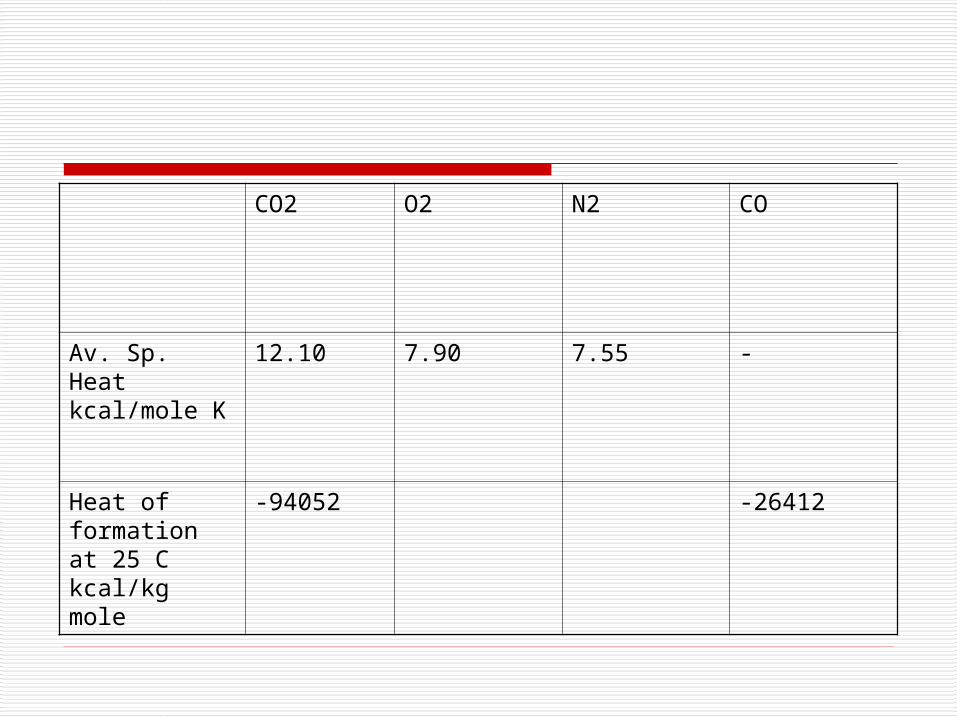
CO2 O2 N2 CO
Av. Sp. Heat kcal/mole K
12.10 7.90 7.55 -
Heat of formation at 25 C kcal/kg mole
-94052 -26412
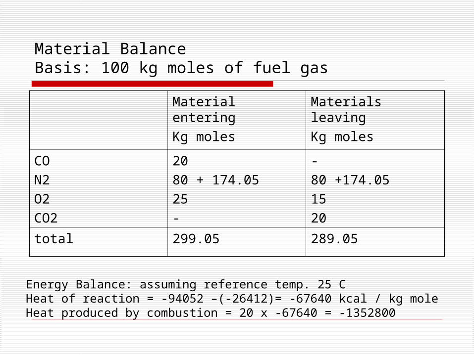
Material BalanceBasis: 100 kg moles of fuel gas
Material enteringKg moles
Materials leavingKg moles
CON2O2CO2
2080 + 174.0525-
-80 +174.051520
total 299.05 289.05
Energy Balance: assuming reference temp. 25 CHeat of reaction = -94052 –(-26412)= -67640 kcal / kg moleHeat produced by combustion = 20 x -67640 = -1352800
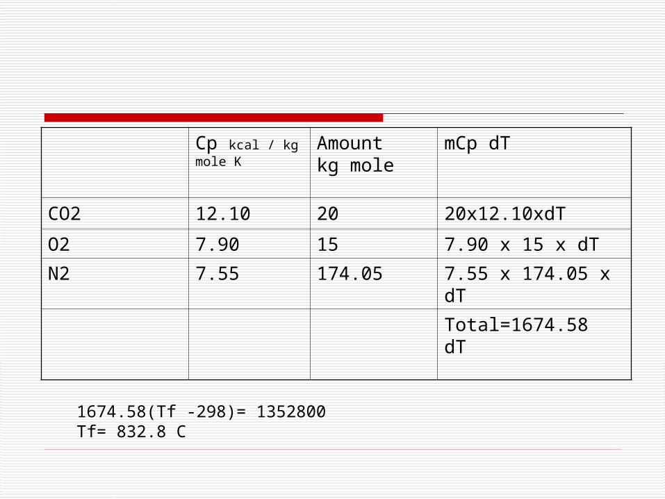
Cp kcal / kg mole K
Amount kg mole
mCp dT
CO2 12.10 20 20x12.10xdT
O2 7.90 15 7.90 x 15 x dT
N2 7.55 174.05 7.55 x 174.05 x dT
Total=1674.58 dT
1674.58(Tf -298)= 1352800Tf= 832.8 C
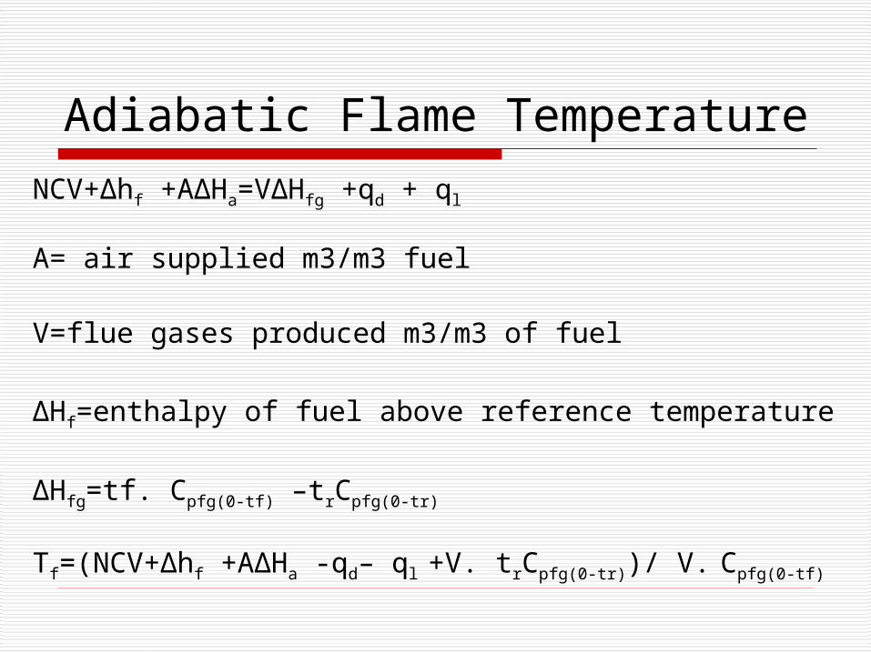
Adiabatic Flame Temperature
NCV+∆hf +A∆Ha=V∆Hfg +qd + ql
A= air supplied m3/m3 fuel
V=flue gases produced m3/m3 of fuel
∆Hf=enthalpy of fuel above reference temperature
∆Hfg=tf. Cpfg(0-tf) –trCpfg(0-tr)
Tf=(NCV+∆hf +A∆Ha -qd– ql +V. trCpfg(0-tr))/ V. Cpfg(0-tf)
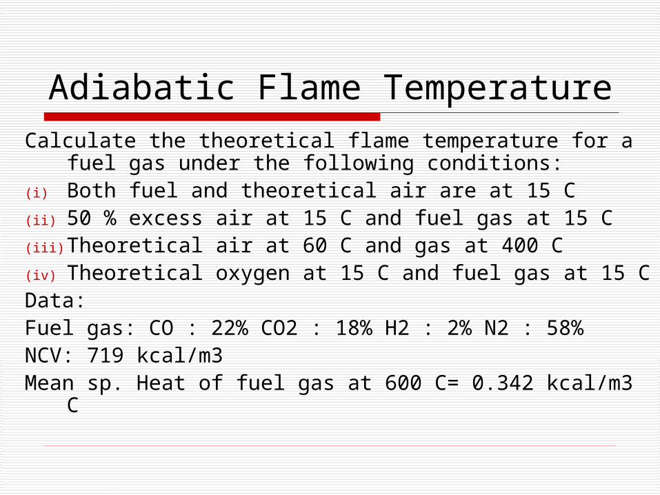
Adiabatic Flame TemperatureCalculate the theoretical flame temperature for a fuel
gas under the following conditions:(i) Both fuel and theoretical air are at 15 C(ii) 50 % excess air at 15 C and fuel gas at 15 C(iii) Theoretical air at 60 C and gas at 400 C(iv) Theoretical oxygen at 15 C and fuel gas at 15 CData:Fuel gas: CO : 22% CO2 : 18% H2 : 2% N2 : 58%NCV: 719 kcal/m3Mean sp. Heat of fuel gas at 600 C= 0.342 kcal/m3 C