Embed Size (px)
Citation preview
G-1
G
Linear GageIdeal for integration into harsh environments such as automation applications
Mitutoyo operates a policy of continuous improvement that aims to provide the customer with the benefi t of the latest technological advances.Therefore the company reserves the right to change any or all aspects of any product specifi cation without notice.
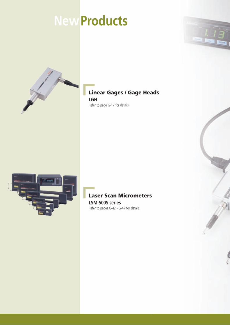
Linear Gages / Gage HeadsLGHRefer to page G-17 for details.
Laser Scan MicrometersLSM-500S seriesRefer to pages G-42 - G-47 for details.
Laser Scan MicrometersLaser Indicators
Automatic Measuring Instruments
NewProducts
G-2Mitutoyo operates a policy of continuous improvement that aims to provide the customer with the benefi t of the latest technological advances.Therefore the company reserves the right to change any or all aspects of any product specifi cation without notice.
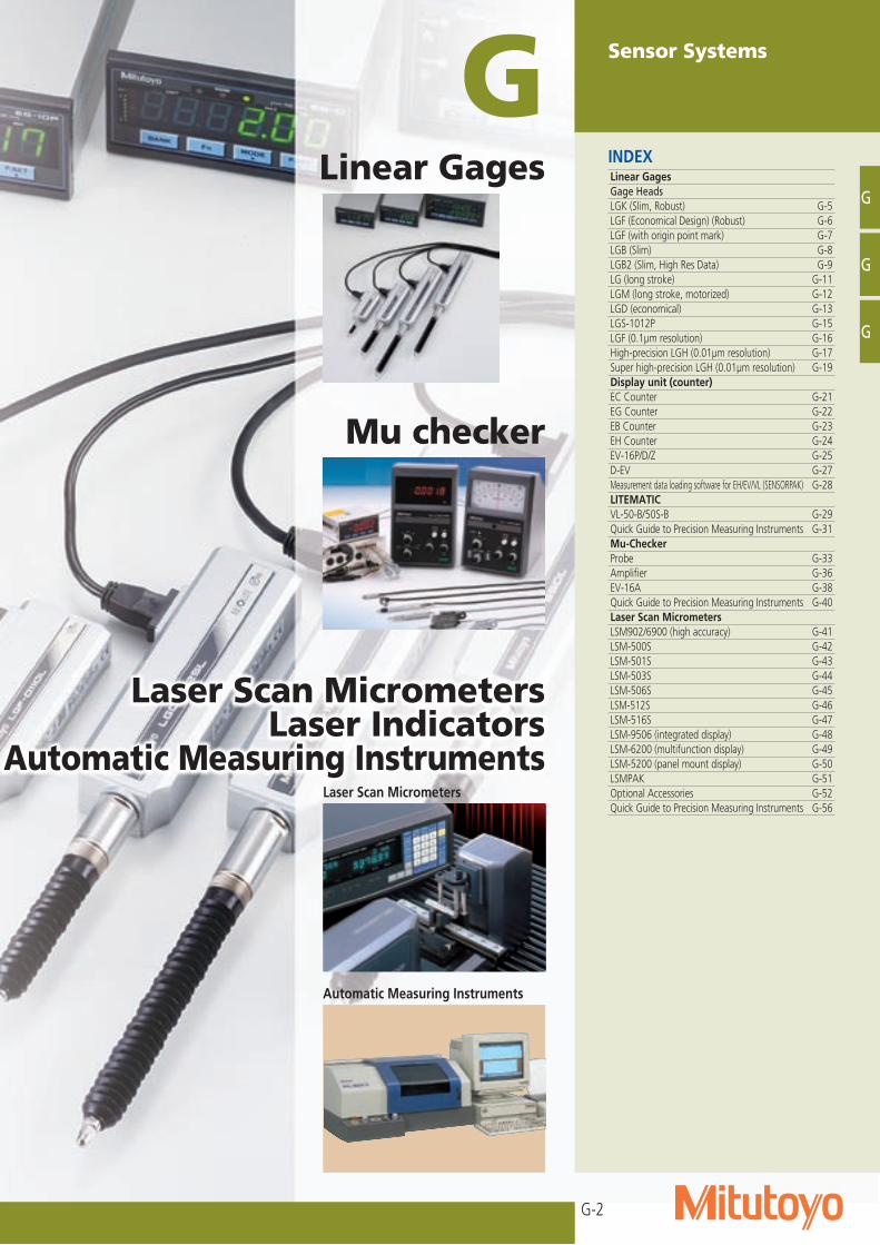
Sensor SystemsGINDEXLinear GagesGage HeadsLGK (Slim, Robust) G-5LGF (Economical Design) (Robust) G-6LGF (with origin point mark) G-7LGB (Slim) G-8LGB2 (Slim, High Res Data) G-9LG (long stroke) G-11LGM (long stroke, motorized) G-12LGD (economical) G-13LGS-1012P G-15LGF (0.1μm resolution) G-16High-precision LGH (0.01μm resolution) G-17Super high-precision LGH (0.01μm resolution) G-19Display unit (counter)EC Counter G-21EG Counter G-22EB Counter G-23EH Counter G-24EV-16P/D/Z G-25D-EV G-27Measurement data loading software for EH/EV/VL (SENSORPAK) G-28LITEMATICVL-50-B/50S-B G-29Quick Guide to Precision Measuring Instruments G-31Mu-CheckerProbe G-33Amplifi er G-36EV-16A G-38Quick Guide to Precision Measuring Instruments G-40Laser Scan MicrometersLSM902/6900 (high accuracy) G-41LSM-500S G-42LSM-501S G-43LSM-503S G-44LSM-506S G-45LSM-512S G-46LSM-516S G-47LSM-9506 (integrated display) G-48LSM-6200 (multifunction display) G-49LSM-5200 (panel mount display) G-50LSMPAK G-51Optional Accessories G-52Quick Guide to Precision Measuring Instruments G-56
G
G
G
Laser Scan MicrometersLaser Indicators
Automatic Measuring Instruments
Linear Gages
Laser Scan Micrometers
Mu checker
Automatic Measuring Instruments
G-3
G
Mitutoyo operates a policy of continuous improvement that aims to provide the customer with the benefit of the latest technological advances.Therefore the company reserves the right to change any or all aspects of any product specification without notice.
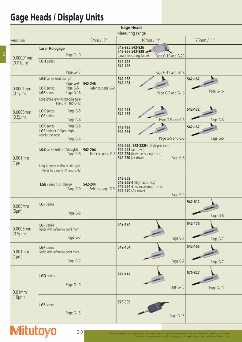
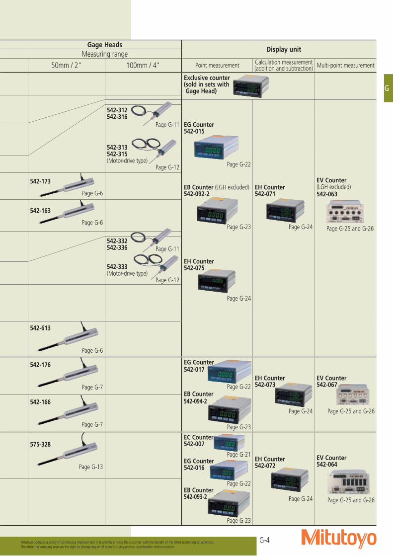
Gage Heads / Display UnitsGage Heads
Display unitMeasuring range
50mm / 2" 100mm / 4" Point measurement Calculation measurement (addition and subtraction) Multi-point measurement
Exclusive counter(sold in sets with Gage Head)
542-312542-316
Page G-11
542-313542-315(Motor-drive type)
Page G-12
EG Counter542-015
Page G-22
EV Counter (LGH excluded)542-063
Page G-25 and G-26
542-173
Page G-6EB Counter (LGH excluded)542-092-2
Page G-23
EH Counter542-071
Page G-24
542-163
Page G-6
542-332542-336 Page G-11
542-333(Motor-drive type)
Page G-12
EH Counter542-075
Page G-24
542-613
Page G-6
542-176
Page G-7
EG Counter542-017
Page G-22EB Counter542-094-2
Page G-23
EH Counter542-073
Page G-24
EV Counter542-067
Page G-25 and G-26542-166
Page G-7
575-328
Page G-13
EC Counter542-007
Page G-21EG Counter542-016
Page G-22EB Counter542-093-2
Page G-23
EH Counter542-072
Page G-24
EV Counter542-064
Page G-25 and G-26
Gage HeadsMeasuring range
Resolution 5mm / .2" 10mm / .4" 25mm / .1"
0.00001mm(0.01μm)
Laser Hologage
Page G-19
542-925,542-926542-927,542-928(Low measuring force) Page G-19 and G-20
LGH series
Page G-17
542-715542-716
Page G-17 and G-18
0.0001mm(0.1μm)
LGB series (nut clamp) Page G-9LGK series Page G-5LGF series Page G-16
542-246Refer to page G-9
542-158542-181
Page G-5 and G-16
542-182
Page G-16
Long Stroke series (Motor-drive type)Page G-11 and G-12
0.0005mm(0.5μm)
LGK series Page G-5LGF series
Page G-6
542-171542-157
Page G-5 and G-6
542-172
Page G-6
0.001mm(1μm)
LGK series Page G-5LGF series • 0.5μm high-resolution type
Page G-6
542-156542-161
Page G-5 and G-6
542-162
Page G-6
LGB series (ø8mm Straight)Page G-8
542-204Refer to page G-8
542-222, 542-222H (High-precision) 542-223 (air drive)542-224 (Low measuring force) 542-230 (air drive) Page G-8
Long Stroke series (Motor-drive type)Refer to page G-11 and G-12
LGB series (nut clamp)Page G-9
542-244Refer to page G-9
542-262542-262H (High accuracy)542-264 (Low measuring force)542-270 (Air drive)
Page G-9
0.005mm(5μm)
LGF series
Page G-6
542-612
Page G-6
0.0005mm(0.5μm)
LGF series Series with reference point mark
Page G-7
542-174
Page G-7
542-175
Page G-7
0.001mm(1μm)
LGF series Series with reference point mark
Page G-7
542-164
Page G-7
542-165
Page G-7
0.01mm(10μm)
LGD series
Page G-13
575-326
Page G-13
575-327
Page G-13
LGS series
Page G-15
575-303
Page G-15
G-4
G
Mitutoyo operates a policy of continuous improvement that aims to provide the customer with the benefit of the latest technological advances.Therefore the company reserves the right to change any or all aspects of any product specification without notice.
Gage HeadsDisplay unit
Measuring range50mm / 2" 100mm / 4" Point measurement Calculation measurement
(addition and subtraction) Multi-point measurement
Exclusive counter(sold in sets with Gage Head)
542-312542-316
Page G-11
542-313542-315(Motor-drive type)
Page G-12
EG Counter542-015
Page G-22
EV Counter (LGH excluded)542-063
Page G-25 and G-26
542-173
Page G-6EB Counter (LGH excluded)542-092-2
Page G-23
EH Counter542-071
Page G-24
542-163
Page G-6
542-332542-336 Page G-11
542-333(Motor-drive type)
Page G-12
EH Counter542-075
Page G-24
542-613
Page G-6
542-176
Page G-7
EG Counter542-017
Page G-22EB Counter542-094-2
Page G-23
EH Counter542-073
Page G-24
EV Counter542-067
Page G-25 and G-26542-166
Page G-7
575-328
Page G-13
EC Counter542-007
Page G-21EG Counter542-016
Page G-22EB Counter542-093-2
Page G-23
EH Counter542-072
Page G-24
EV Counter542-064
Page G-25 and G-26
Gage HeadsMeasuring range
Resolution 5mm / .2" 10mm / .4" 25mm / .1"
0.00001mm(0.01μm)
Laser Hologage
Page G-19
542-925,542-926542-927,542-928(Low measuring force) Page G-19 and G-20
LGH series
Page G-17
542-715542-716
Page G-17 and G-18
0.0001mm(0.1μm)
LGB series (nut clamp) Page G-9LGK series Page G-5LGF series Page G-16
542-246Refer to page G-9
542-158542-181
Page G-5 and G-16
542-182
Page G-16
Long Stroke series (Motor-drive type)Page G-11 and G-12
0.0005mm(0.5μm)
LGK series Page G-5LGF series
Page G-6
542-171542-157
Page G-5 and G-6
542-172
Page G-6
0.001mm(1μm)
LGK series Page G-5LGF series • 0.5μm high-resolution type
Page G-6
542-156542-161
Page G-5 and G-6
542-162
Page G-6
LGB series (ø8mm Straight)Page G-8
542-204Refer to page G-8
542-222, 542-222H (High-precision) 542-223 (air drive)542-224 (Low measuring force) 542-230 (air drive) Page G-8
Long Stroke series (Motor-drive type)Refer to page G-11 and G-12
LGB series (nut clamp)Page G-9
542-244Refer to page G-9
542-262542-262H (High accuracy)542-264 (Low measuring force)542-270 (Air drive)
Page G-9
0.005mm(5μm)
LGF series
Page G-6
542-612
Page G-6
0.0005mm(0.5μm)
LGF series Series with reference point mark
Page G-7
542-174
Page G-7
542-175
Page G-7
0.001mm(1μm)
LGF series Series with reference point mark
Page G-7
542-164
Page G-7
542-165
Page G-7
0.01mm(10μm)
LGD series
Page G-13
575-326
Page G-13
575-327
Page G-13
LGS series
Page G-15
575-303
Page G-15
G-5
G
Linear GageIdeal for integration into harsh environments such as automation applications
Mitutoyo operates a policy of continuous improvement that aims to provide the customer with the benefit of the latest technological advances.Therefore the company reserves the right to change any or all aspects of any product specification without notice.
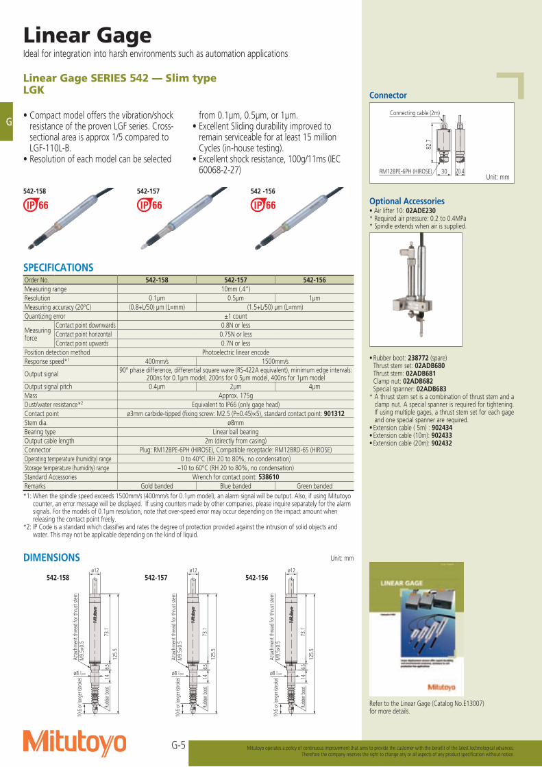
Linear Gage SERIES 542 — Slim typeLGK
• Compact model offers the vibration/shock resistance of the proven LGF series. Cross-sectional area is approx 1/5 compared to LGF-110L-B.
• Resolution of each model can be selected
from 0.1μm, 0.5μm, or 1μm.• Excellent Sliding durability improved to
remain serviceable for at least 15 million Cycles (in-house testing).
• Excellent shock resistance, 100g/11ms (IEC 60068-2-27)
Unit: mm
82.7
30 20.4
Connecting cable (2m)
RM12BPE-6PH (HIROSE)Unit: mm
SPECIFICATIONSOrder No. 542-158 542-157 542-156Measuring range 10mm (.4”)Resolution 0.1μm 0.5μm 1μmMeasuring accuracy (20°C) (0.8+L/50) μm (L=mm) (1.5+L/50) μm (L=mm)Quantizing error ±1 count
Measuring force
Contact point downwards 0.8N or lessContact point horizontal 0.75N or lessContact point upwards 0.7N or less
Position detection method Photoelectric linear encodeResponse speed*1 400mm/s 1500mm/s
Output signal 90° phase difference, differential square wave (RS-422A equivalent), minimum edge intervals: 200ns for 0.1μm model, 200ns for 0.5μm model, 400ns for 1μm model
Output signal pitch 0.4μm 2μm 4μmMass Approx. 175gDust/water resistance*2 Equivalent to IP66 (only gage head)Contact point ø3mm carbide-tipped (fixing screw: M2.5 (P=0.45)×5), standard contact point: 901312Stem dia. ø8mmBearing type Linear ball bearingOutput cable length 2m (directly from casing)Connector Plug: RM12BPE-6PH (HIROSE), Compatible receptacle: RM12BRD-6S (HIROSE)Operating temperature (humidity) range 0 to 40°C (RH 20 to 80%, no condensation)Storage temperature (humidity) range –10 to 60°C (RH 20 to 80%, no condensation)Standard Accessories Wrench for contact point: 538610Remarks Gold banded Blue banded Green banded*1: When the spindle speed exceeds 1500mm/s (400mm/s for 0.1μm model), an alarm signal will be output. Also, if using Mitutoyo
counter, an error message will be displayed. If using counters made by other companies, please inquire separately for the alarm signals. For the models of 0.1μm resolution, note that over-speed error may occur depending on the impact amount when releasing the contact point freely.
*2: IP Code is a standard which classifies and rates the degree of protection provided against the intrusion of solid objects and water. This may not be applicable depending on the kind of liquid.
542-158 542-157 542 -156
DIMENSIONS
Atta
chm
ent t
hrea
d fo
r thr
ust s
tem
M9.
5×0.
510
.6 o
r lon
ger (
strok
e)
Rubb
er bo
ot
ø8 –0.0090
146.5
73.1
ø12
125.
5
Atta
chm
ent t
hrea
d fo
r thr
ust s
tem
M9.
5×0.
510
.6 o
r lon
ger (
strok
e)
Rubb
er bo
ot
ø8 –0.0090
146.5
73.1
ø12
125.
5
542-158 542-157
Atta
chm
ent t
hrea
d fo
r thr
ust s
tem
M9.
5×0.
510
.6 o
r lon
ger (
strok
e)
Rubb
er bo
ot
ø8 –0.0090
146.5
73.1
ø12
125.
5
542-156
Connector
Optional Accessories• Air lifter 10: 02ADE230* Required air pressure: 0.2 to 0.4MPa* Spindle extends when air is supplied.
• Rubber boot: 238772 (spare) Thrust stem set: 02ADB680 Thrust stem: 02ADB681 Clamp nut: 02ADB682 Special spanner: 02ADB683* A thrust stem set is a combination of thrust stem and a
clamp nut. A special spanner is required for tightening. If using multiple gages, a thrust stem set for each gage and one special spanner are required.
• Extension cable ( 5m) : 902434• Extension cable (10m): 902433• Extension cable (20m): 902432
Refer to the Linear Gage (Catalog No.E13007) for more details.
G-6
G
Mitutoyo operates a policy of continuous improvement that aims to provide the customer with the benefit of the latest technological advances.Therefore the company reserves the right to change any or all aspects of any product specification without notice.
M18×1
Rubber boot
Thrust stem
Clamp nut
02ADN371
02ADB692
Dim
ensio
ns
with
a th
rust
stem
insta
lled
(screw top height)
Cable length, 2m
51.5
or l
onge
r (st
roke
)
M14×0.5Attachment thread for thrust stem
142
34
13.8
(316
)
0.6
ø15-0.015 0
61.720.6
56.1
8.6
41
ø18
18.5
9 5
ø18 -0.018 0
(24.2)
21
4.5
124.
9
174
629
.6
20
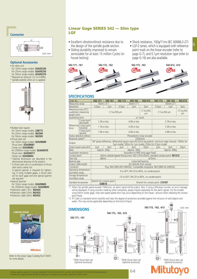
Linear Gage SERIES 542 — Slim typeLGF
• Excellent vibration/shock resistance due to the design of the spindle guide section.
• Sliding durability improved to remain serviceable for at least 15 million Cycles (in-house testing).
• Shock resistance, 100g/11ms (IEC 60068-2-27)• LGF-Z series, which is equipped with reference
point mark on the linear encoder (refer to page G-7), and 0.1μm resolution type (refer to page G-16) are also available.
Unit: mm
*With thrust stem set (optional accessory)
*With thrust stem set (optional accessory)
*With thrust stem set (optional accessory)
542-171, -161 542-172, -162 542-173, -163
ø18
41
ø11.8
DIMENSIONS
542-171, -161
542-172, -162, -612
542-173, -163, -613
Connector
542-612, -613
M9.5×0.5
Attachment thread for thrust stem
M9.5×0.5
Clamp nut02ADB682
Thrust stem02ADB681
(screw top height)
10.6
or l
onge
r (str
oke)
Cable length, 2m
Dim
ensio
ns w
ith a
thru
st ste
m in
stalle
d
12
(13.8)
ø9.5-0.015 0
414.5
9.5
6
17.3
ø8-0.009 0
12.3
34
(129
.5)
15.4 61.5
46.9
ø18
41
14.80.6
75.7
14
6.9
545
.9
Rubber boot
Cable length, 2m
(screw top height)
M14×0.5Attachment thread for thrust stem
Dim
ensio
ns w
ith a
thru
st ste
m in
stalle
d
M18×1
Thrust stem
Clamp nut
02ADN371
02ADB692
21
(24.2)
ø18-0.018 0
5918.5
ø18
41
20.6
30.7
61.7
ø15-0.015 0
13.8
26 o
r lon
ger
(stro
ke)
(208
.3)
34
8.6
93.6
114.
76.
522
200.6
4.5
84.1
Rubber boot
Optional Accessories• Air drive unit For 10mm range models: 02ADE230 For 25mm range models: 02ADE250 For 50mm range models: 02ADE270* Required air pressure: 0.2 to 0.4MPa* Spindle extends when air is supplied.
Unit: mm
• Rubber boot (spare) For 10mm range models: 238772 For 25mm range models: 962504 For 50mm range models: 962505• Thrust stem set For 10mm range models: 02ADB680 Thrust stem: 02ADB681 Clamp nut: 02ADB682 For 25/50mm range models: 02ADN370 Thrust stem: 02ADN371 Clamp nut: 02ADB692* External dimensions are described in the
dimensional drawing of the product.* A thrust stem set is a combination of thrust
stem and a clamp nut. A special spanner is required for tighten-
ing. If using multiple gages, a thrust stem set for each gage and one special spanner are required.
• Special spanner For 10mm range models: 02ADB683 For 25/50mm range models: 02ADB693• Extension cable ( 5m) : 902434• Extension cable (10m): 902433• Extension cable (20m): 902432
Refer to the Linear Gage (Catalog No.E13007) for more details.
SPECIFICATIONSOrder No. 542-171 542-161 542-172 542-162 542-612 542-173 542-163 542-613Measuring range 10mm (.4”) 25mm (1”) 50mm (2”)Resolution 0.5μm 1μm 0.5μm 1μm 5μm 0.5μm 1μm 5μmMeasuring accuracy (20°C)L=arbitrary measuring length (mm)
(1.5+L/50) μm (7.5+L/50)μm (1.5+L/50) μm (7.5+L/50)
μm
Quantizing error ±1 count
Measuring force
Contact point downwards 1.2N or less 4.6N or less 5.7N or less
Contact point horizontal 1.1N or less 4.3N or less 5.3N or less
Contact point upwards 1.0N or less 4.0N or less 4.9N or less
Position detection method Photoelectric linear encoderResponse speed*1 1500mm/s
Output 90° phase difference, differential square wave (RS-422A equivalent), minimum edge intervals: 1000ns for 5μm model, 500ns for 1μm model, 250ns for 0.5μm model
Output square wave pitch 2μm 4μm 2μm 4μm 20μm 2μm 4μm 20μmMass Approx. 260g Approx. 300g Approx. 400gDust/water resistance Equivalent to IP66 (only gage head)Contact point ø3mm carbide-tipped (fixing screw: M2.5 (P=0.45)×5), standard contact point: 901312Stem dia. ø8mm ø15mmBearing type Linear ball bearingOutput cable length 2m (directly from casing)Connector Plug: RM12BPE-6PH (HIROSE), Compatible receptacle: RM12BRD-6S (HIROSE)Operating temperature (humidity) range 0 to 40°C (RH 20 to 80%, no condensation)
Storage temperature (humidity) range –10 to 60°C (RH 20 to 80%, no condensation)
Standard Accessories Wrench for contact point: 538610 Wrench for contact point: 210187
*1: When the spindle speed exceeds 1500mm/s, an alarm signal will be output. Also, if using a Mitutoyo counter, an error message will be displayed. If using counters made by other companies, please inquire separately for the alarm signals. For the models using 50mm stroke gage, note over-speed speed error may occur depending on the impact amount when releasing the contact point freely.
*2: IP Code is a standard which classifies and rates the degree of protection provided against the intrusion of solid objects and water. This may not be applicable depending on the kind of liquid.
G-7
G
Linear GageIdeal for integration into harsh environments such as automation applications
Mitutoyo operates a policy of continuous improvement that aims to provide the customer with the benefit of the latest technological advances.Therefore the company reserves the right to change any or all aspects of any product specification without notice.
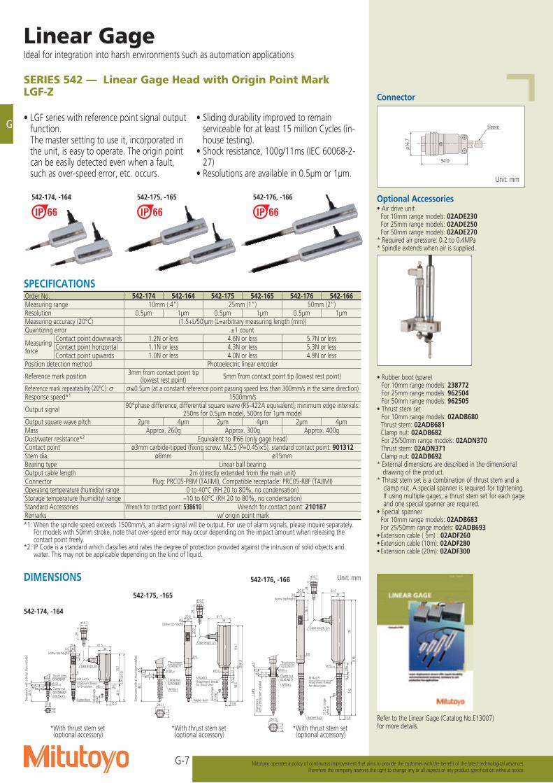
SERIES 542 — Linear Gage Head with Origin Point MarkLGF-Z
• LGF series with reference point signal output function.
The master setting to use it, incorporated in the unit, is easy to operate. The origin point can be easily detected even when a fault, such as over-speed error, etc. occurs.
• Sliding durability improved to remain serviceable for at least 15 million Cycles (in-house testing).
• Shock resistance, 100g/11ms (IEC 60068-2-27)
• Resolutions are available in 0.5μm or 1μm.
542-174, -164
542-175, -165
Unit: mm
Connector
Sleeve
ø16.
7
34.0
(screw top height)
10.6
or lo
nger
(stro
ke)
Cable length, 2m
Dim
ensio
ns w
ith a
thru
st ste
m in
stalle
d
M9.5×0.5
Attachment thread for thrust stem
M9.5×0.5
Clamp nut02ADB682
Thrust stem02ADB681
6
17.3
ø8-0.009 0
12.3
3461.5
46.9
15.4
ø16.7
34
12
(13.8)
ø9.5-0.015 0
414.5
9.5
14.80.6
75.7
14
6.9
(129
.5)
545
.9
Rubber boot
Attachment thread for thrust stem
M14×0.5
(screw top height)
Cable length, 2m
26 o
r lon
ger
(stro
ke)
02ADB692
02ADN371
Clamp nut
Thrust stem
M18×1
Dim
ensio
ns w
ith a
thru
st ste
m in
stalle
d
18.5
9 5
ø18-0.018 0
(24.2)
21
34
ø16.7
93.6
8.6
34
(208
.3)
13.8
ø15-0.015 0
61.7
30.7
20.6
4.5
84.1
200.6
114.
76.
522
Rubber boot
Dim
ensio
ns
with
a th
rust
stem
insta
lled
(screw top height)
Cable length, 2m
51.5
or l
onge
r (st
roke
)
M14×0.5Attachment thread for thrust stemM18×1
Thrust stem
Clamp nut
02ADN371
02ADN371
18.5
9 5
ø18-0.018 0
(24.2)
21
34
ø16.7
142
34
13.8
(316
)
0.6
ø15-0.015 0
61.720.6
56.1
8.6
4.5
124.
9
174
629
.6
20
Rubber boot
542-176, -166
Optional Accessories• Air drive unit For 10mm range models: 02ADE230 For 25mm range models: 02ADE250 For 50mm range models: 02ADE270* Required air pressure: 0.2 to 0.4MPa* Spindle extends when air is supplied.
• Rubber boot (spare) For 10mm range models: 238772 For 25mm range models: 962504 For 50mm range models: 962505• Thrust stem set For 10mm range models: 02ADB680 Thrust stem: 02ADB681 Clamp nut: 02ADB682 For 25/50mm range models: 02ADN370 Thrust stem: 02ADN371 Clamp nut: 02ADB692* External dimensions are described in the dimensional
drawing of the product.* Thrust stem set is a combination of thrust stem and a
clamp nut. A special spanner is required for tightening. If using multiple gages, a thrust stem set for each gage and one special spanner are required.
• Special spanner For 10mm range models: 02ADB683 For 25/50mm range models: 02ADB693• Extension cable ( 5m) : 02ADF260• Extension cable (10m): 02ADF280• Extension cable (20m): 02ADF300
SPECIFICATIONSOrder No. 542-174 542-164 542-175 542-165 542-176 542-166Measuring range 10mm (.4”) 25mm (1”) 50mm (2”)Resolution 0.5μm 1μm 0.5μm 1μm 0.5μm 1μmMeasuring accuracy (20°C) (1.5+L/50)μm (L=arbitrary measuring length (mm))Quantizing error ±1 count
Measuring force
Contact point downwards 1.2N or less 4.6N or less 5.7N or lessContact point horizontal 1.1N or less 4.3N or less 5.3N or lessContact point upwards 1.0N or less 4.0N or less 4.9N or less
Position detection method Photoelectric linear encoder
Reference mark position 3mm from contact point tip (lowest rest point) 5mm from contact point tip (lowest rest point)
Reference mark repeatability (20°C): ≤0.5μm (at a constant reference point passing speed less than 300mm/s in the same direction)Response speed*1 1500mm/s
Output signal 90° phase difference, differential square wave (RS-422A equivalent), minimum edge intervals: 250ns for 0.5μm model, 500ns for 1μm model
Output square wave pitch 2μm 4μm 2μm 4μm 2μm 4μmMass Approx. 260g Approx. 300g Approx. 400gDust/water resistance*2 Equivalent to IP66 (only gage head)Contact point ø3mm carbide-tipped (fixing screw: M2.5 (P=0.45)×5), standard contact point: 901312Stem dia. ø8mm ø15mmBearing type Linear ball bearingOutput cable length 2m (directly extended from the main unit)Connector Plug: PRC05-P8M (TAJIMI), Compatible receptacle: PRC05-R8F (TAJIMI)Operating temperature (humidity) range 0 to 40°C (RH 20 to 80%, no condensation)Storage temperature (humidity) range –10 to 60°C (RH 20 to 80%, no condensation)Standard Accessories Wrench for contact point: 538610 Wrench for contact point: 210187Remarks w/ origin point mark*1: When the spindle speed exceeds 1500mm/s, an alarm signal will be output. For use of alarm signals, please inquire separately.
For models with 50mm stroke, note that over-speed error may occur depending on the impact amount when releasing the contact point freely.
*2: IP Code is a standard which classifies and rates the degree of protection provided against the intrusion of solid objects and water. This may not be applicable depending on the kind of liquid.
Unit: mmDIMENSIONS
Refer to the Linear Gage (Catalog No.E13007) for more details.
542-174, -164 542-175, -165 542-176, -166
*With thrust stem set (optional accessory)
*With thrust stem set (optional accessory)
*With thrust stem set (optional accessory)
G-8
G
Mitutoyo operates a policy of continuous improvement that aims to provide the customer with the benefit of the latest technological advances.Therefore the company reserves the right to change any or all aspects of any product specification without notice.
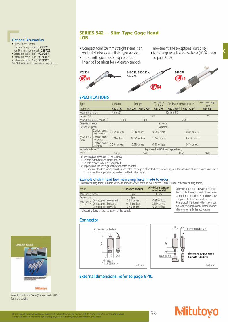
SERIES 542 — Slim Type Gage HeadLGB
• Compact form (ø8mm straight stem) is an optimal choice as a built-in type sensor.
• The spindle guide uses high precision linear ball bearings for extremely smooth
movement and exceptional durability.• Nut clamp type is also available (LGB2: refer
to page G-9).
20.430
4710
0
Connecting cable (2m)
Dsub 15 pin
Unit: mm Unit: mm
Example of slim head low measuring force (made to order)• Low measuring force, suitable for measurement of soft-material workpieces (Consult us for other measuring forces).
Connector
20.430
82.7
Connecting cable (2m)
(HIROSE)RM12BPE-6PH
External dimensions: refer to page G-10.
Depending on the operating method, the spindle forward speed of low mea-suring force model may become slow compared to the standard model. Please check if this restriction is compat-ible with the application. Please contact Mitutoyo to verify the application.
Optional Accessories• Rubber boot (spare) For 5mm range models: 238773 For 10mm range models: 238772• Extension cable ( 5m) : 902434*6
• Extension cable (10m): 902433*6
• Extension cable (20m): 902432*6
*6: Not available for sine-wave output type.
Refer to the Linear Gage (Catalog No.E13007) for more details.
542-230
SPECIFICATIONSType L-shaped Straight Low measur-
ing force Air-driven contact point *1 Sine-wave output type
Order No. 542-204 542-222 542-222H 542-224 542-230*2 542-223*3 542-401Measuring range 5mm (.2”) 10mm (.4”)Resolution 1μm *4
Measuring accuracy (20°C) 2μm 1μm 2μmQuantizing error ±1 countResponse speed 900mm/s
Measuring force
Contact point downwards 0.65N or less 0.8N or less 0.6N or less 0.8N or less
Contact point horizontal 0.6N or less 0.75N or less 0.55N or less 0.75N or less
Contact point upwards 0.55N or less 0.7N or less 0.5N or less 0.7N or less
Protection Level*5 Equivalent to IP54 (only gage head)Mass 145g 140g 165g 160g*1: Required air pressure: 0.3 to 0.4MPa*2: Spindle extends when air is supplied. *3: Spindle retracts when air is supplied.*4: Depends on the settings of the connected counter.*5: IP Code is a standard which classifies and rates the degree of protection provided against the intrusion of solid objects and water.
This may not be applicable depending on the kind of liquid.
Model L-shaped model Air-driven contact point model
Measuring range 5μm 10μmResolution 1μm 1μm
Measuring force*
Contact point downwards 0.5N or less 0.6N or lessContact point horizontal 0.45N or less 0.55N or lessContact point upwards 0.4N or less 0.5N or less
* Measuring force at the retraction of the spindle
Sine wave output model(542-401, 542-421)
542-222, 542-222H, 542-224
542-204
G-9
G
Linear GageIdeal for integration into harsh environments such as automation applications
Mitutoyo operates a policy of continuous improvement that aims to provide the customer with the benefit of the latest technological advances.Therefore the company reserves the right to change any or all aspects of any product specification without notice.
Connector
Example of slim head low measuring force (made to order)• Low measuring force, suitable for measurement of soft-material workpieces (Consult us for other measuring forces).
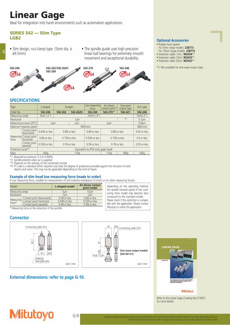
SERIES 542 — Slim TypeLGB2
• Slim design, nut clamp type (Stem dia. is ø9.5mm)
• The spindle guide uses high precision linear ball bearings for extremely smooth movement and exceptional durability.
542-244 542-262/542-262H
20.430
4710
0
Connecting cable (2m)
Dsub 15 pin
Unit: mmUnit: mm
20.430
82.7
Connecting cable (2m)
(HIROSE)RM12BPE-6PH
542-264
External dimensions: refer to page G-10.
542-270
Optional Accessories• Rubber boot (spare) For 5mm range models: 238773 For 10mm range models: 238772• Extension cable ( 5m) : 902434*5
• Extension cable (10m): 902433*5
• Extension cable (20m): 902432*5
*5: Not available for sine-wave output type.
Refer to the Linear Gage (Catalog No.E13007) for more details.
SPECIFICATIONSType L-shaped Straight Low measuring
forceAir-driven
contact point*1Sine-wave
output type Slim type
Order No. 542-244 542-262 542-262H 542-264 542-270*2 542-421 542-246Measuring range 5mm (.2”) 10mm (.4”) 5mm(.2")Resolution 1μm *3 0.1μmMeasuring accuracy (20°C) 2μm 1μm 2μm 0.8μmMaximum response speed 900mm/s 380mm/s
Measuring force
Contact point downwards 0.65N or less 0.8N or less 0.6N or less 0.8N or less 0.65 or less
Contact point horizontal 0.6N or less 0.75N or less 0.55N or less 0.75N or less 0.6 or less
Contact point upwards 0.55N or less 0.7N or less 0.5N or less 0.7N or less 0.55 or less
Protection Level*4 Equivalent to IP54 (only gage head)Mass 160g 170g 170g 180g 160g*1: Required air pressure: 0.3 to 0.4MPa*2: Spindle extends when air is supplied.*3: Depends on the settings of the connected counter.*4: IP Code is a standard which classifies and rates the degree of protection provided against the intrusion of solid
objects and water. This may not be applicable depending on the kind of liquid.
Sine wave output models(542-401/21)
Depending on the operating method, the spindle forward speed of low mea-suring force model may become slow compared to the standard model. Please check if this restriction is compat-ible with the application. Please contact Mitutoyo to verify the application.
Model L-shaped model Air-driven contact point model
Measuring range 5μm 10μmResolution 1μm 1μm
Measuring force*
Contact point downwards 0.5N or less 0.6N or lessContact point horizontal 0.45N or less 0.55N or lessContact point upwards 0.4N or less 0.5N or less
* Measuring force at the retraction of the spindle
542-246
G-10
G
Mitutoyo operates a policy of continuous improvement that aims to provide the customer with the benefit of the latest technological advances.Therefore the company reserves the right to change any or all aspects of any product specification without notice.
ø918 ø9
ø14ø9.5 0
-0.009756.
315
.925
.1
4.9
(thre
ad)
Clamp nut(Parts No.200365)
L
L=11.5~13.0
Connecting cable (2m)
Refer to the connector section.
Rubber boot
ø9.5 0-0.009
ø4.2ø7.9
ø12
ø14
113 20.2
15.9
34.9
4.9
(thre
ad)
Clamp nut(Parts No.200365)
Knurl
L
L=11.5~13.0
Connecting cable (2m)
Refer to the connector section.
Rubber boot60
.150
.3
1134.
515
.929
.3
φ9.5 0-0.009
移動量
10.4
mm以上締め付けナット
ゴムキャップ
(パーツNo.200365)
平目ローレット
L=11.5~13.0
接続ケーブル(2m)Connecting cable (2m)
コネクタ部参照ください。Refer to the connector section.
60.1
L
39.3
1024.
515
.9ø9.5 0-0.009
Compatible air hose(ID: ø2.5)
Stro
ke10
.4m
m o
r mor
eClamp nut(Parts No.200365)
Knurl
L=11.5~13.0
ø9.5 0-0.009
ø4.2ø7.9
ø12
ø14
113
20.2
15.9
34.9
4.9
(thre
ad)
Clamp nut
Rubber boot(Parts No.200365)
Knurl
L
L=11.5~13.0
Connecting cable (2m)
Refer to the connector section.
ø918 ø9
ø14ø9.5 0
-0.009756.
315
.925
.14.
9 (th
read
) Clamp nut(Parts No.200365)Rubber boot
L
L=11.5~13.0
Connecting cable (2m)
Refer to the connector section.
Connectable to Mitutoyo linear scale counter.
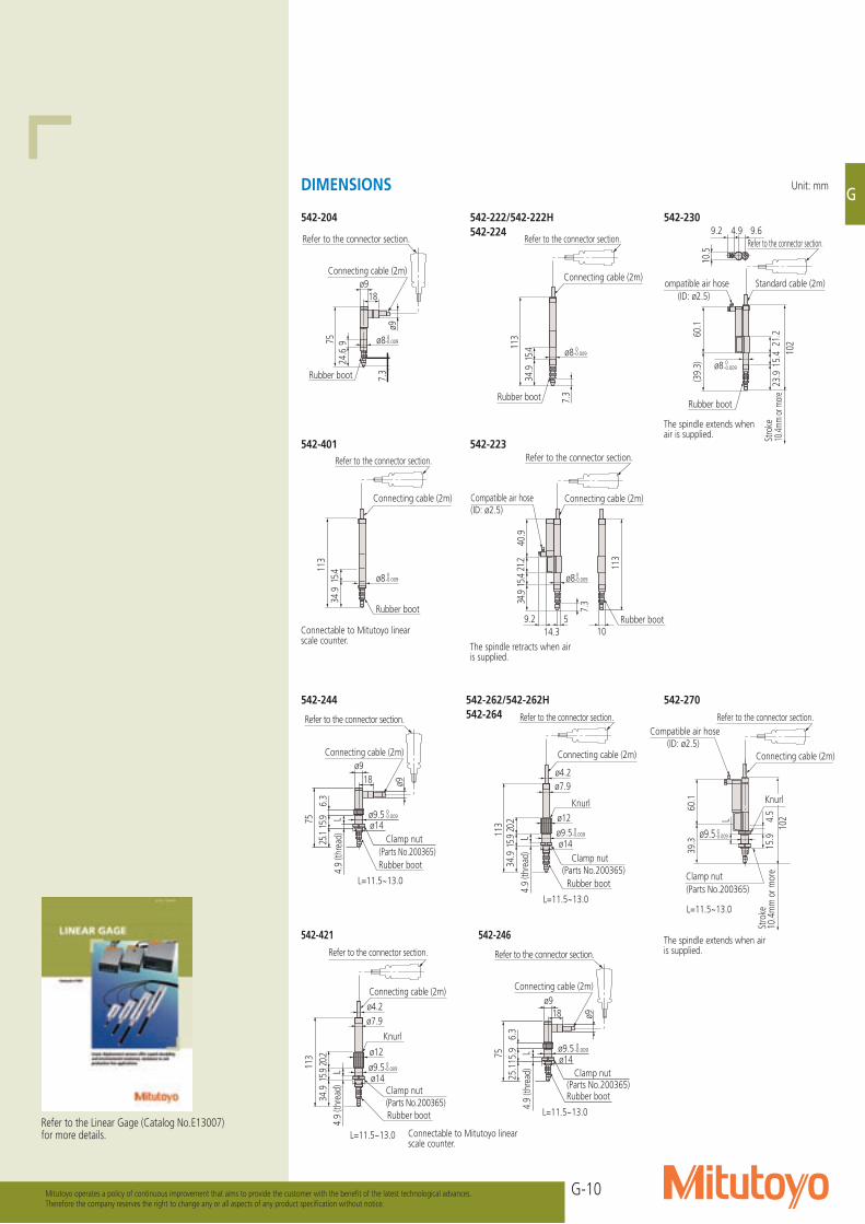
542-244 542-262/542-262H 542-270542-264
542-421 542-246
113
40.9
21.2
15.4
34.9
7.3
ø8 0-0.009
Compatible air hose(ID: ø2.5)
59.214.3 10
Connecting cable (2m)
Refer to the connector section.
Rubber boot
The spindle retracts when air is supplied.
ø918
ø9
ø8924
.675 0
-0.009
7.3
Connecting cable (2m)
Refer to the connector section.
Rubber boot
Rubber boot
Connecting cable (2m)
113
15.4
34.9
ø8 0-0.009
7.3
Refer to the connector section.
ø8 0-0.009
113
15.4
34.9
Connecting cable (2m)
Refer to the connector section.
Rubber boot
60.1
(39.
3)
10221
.215
.423
.9
10.5
ø8 0-0.009
Standard cable (2m)Compatible air hose(ID: ø2.5)
Stro
ke10
.4mm
or m
ore
9.64.99.2Refer to the connector section.
Rubber boot
Connectable to Mitutoyo linear scale counter.
The spindle extends when air is supplied.
The spindle extends when air is supplied.
542-401 542-223
542-204 542-222/542-222H542-224
542-230
Refer to the Linear Gage (Catalog No.E13007) for more details.
Unit: mmDIMENSIONS
G-11
G
Linear GageIdeal for integration into harsh environments such as automation applications
Mitutoyo operates a policy of continuous improvement that aims to provide the customer with the benefit of the latest technological advances.Therefore the company reserves the right to change any or all aspects of any product specification without notice.
Lifting lever attachment
RM12
BPE-
6PH
(HIR
OSE
)
Outp
ut ca
ble
lengt
h, 2
m
2-ø4
.5, ø
9 de
pth
4
33
34
17
ø6
49
50
13
429
Stro
ke 1
02 o
r lon
ger
191.
56
-0.0130ø20
736
243.
568
49 33
34
17
50ø20 0
-0.013
36 7
20
Stro
ke 1
02 o
r lon
ger
Rubb
er b
oot
6724
3.5
473.
5
236
6RM
12BP
E-6P
H (H
IRO
SE)
Outp
ut ca
ble
lengt
h, 2
m
2-ø4
.5, ø
9 de
pth
4
Unit: mm
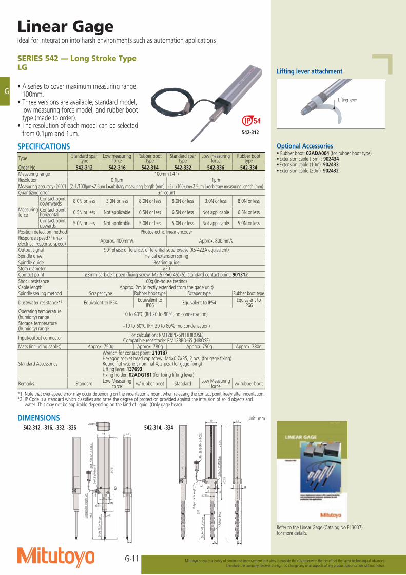
SERIES 542 — Long Stroke TypeLG
• A series to cover maximum measuring range, 100mm.
• Three versions are available; standard model, low measuring force model, and rubber boot type (made to order).
• The resolution of each model can be selected from 0.1μm and 1μm.
542-312, -316, -332, -336
DIMENSIONS542-314, -334
Lifting lever
Optional Accessories• Rubber boot: 02ADA004 (for rubber boot type)• Extension cable ( 5m) : 902434• Extension cable (10m): 902433• Extension cable (20m): 902432
542-312
SPECIFICATIONSType Standard spar
typeLow measuring
forceRubber boot
typeStandard spar
typeLow measuring
forceRubber boot
typeOrder No. 542-312 542-316 542-314 542-332 542-336 542-334Measuring range 100mm (.4”)Resolution 0.1μm 1μmMeasuring accuracy (20°C) (2+L/100)μm≤2.5μm L=arbitrary measuring length (mm) (2+L/100)μm≤2.5μm L=arbitrary measuring length (mm)Quantizing error ±1 count
Measuring force
Contact point downwards 8.0N or less 3.0N or less 8.0N or less 8.0N or less 3.0N or less 8.0N or less
Contact point horizontal 6.5N or less Not applicable 6.5N or less 6.5N or less Not applicable 6.5N or less
Contact point upwards 5.0N or less Not applicable 5.0N or less 5.0N or less Not applicable 5.0N or less
Position detection method Photoelectric linear encoderResponse speed*1 (max. electrical response speed) Approx. 400mm/s Approx. 800mm/s
Output signal 90° phase difference, differential squarewave (RS-422A equivalent)Spindle drive Helical extension springSpindle guide Bearing guideStem diameter ø20Contact point ø3mm carbide-tipped (fixing screw: M2.5 (P=0.45)×5), standard contact point: 901312Shock resistance 60g (in-house testing)Cable length Approx. 2m (directly extended from the gage unit)Spindle sealing method Scraper type Rubber boot type Scraper type Rubber boot type
Dust/water resistance*2 Equivalent to IP54 Equivalent to IP66 Equivalent to IP54 Equivalent to
IP66Operating temperature (humidity) range 0 to 40°C (RH 20 to 80%, no condensation)
Storage temperature (humidity) range –10 to 60°C (RH 20 to 80%, no condensation)
Input/output connector For calculation: RM12BPE-6PH (HIROSE)Compatible receptacle: RM12BRD-6S (HIROSE)
Mass (including cables) Approx. 750g Approx. 780g Approx. 750g Approx. 780g
Standard Accessories
Wrench for contact point: 210187Hexagon socket head cap screw, M4×0.7×35, 2 pcs. (for gage fixing)Round flat washer, nominal 4, 2 pcs. (for gage fixing)Lifting lever: 137693Fixing holder: 02ADG181 (for fixing lifting lever)
Remarks Standard Low Measuring force w/ rubber boot Standard Low Measuring
force w/ rubber boot
*1: Note that over-speed error may occur depending on the indentation amount when releasing the contact point freely after indentation.*2: IP Code is a standard which classifies and rates the degree of protection provided against the intrusion of solid objects and
water. This may not be applicable depending on the kind of liquid. (Only gage head)
Refer to the Linear Gage (Catalog No.E13007) for more details.
G-12
G
Mitutoyo operates a policy of continuous improvement that aims to provide the customer with the benefit of the latest technological advances.Therefore the company reserves the right to change any or all aspects of any product specification without notice.
3349
3650
ø20 0–0.013
7 34
1720
Stro
ke 1
02 o
r lon
ger
Rubb
er b
oot
6724
3.5
473.
5
2-ø4
.5, ø
9 de
pth
4
HR10
A-7P
-6P
(HIR
OSE
)
RM12
BPE-
6PH
(HIR
OSE
)
Outp
ut ca
ble
lengt
h, 2
m23
6
Drive
uni
t cab
le len
gth,
2m
Unit: mm
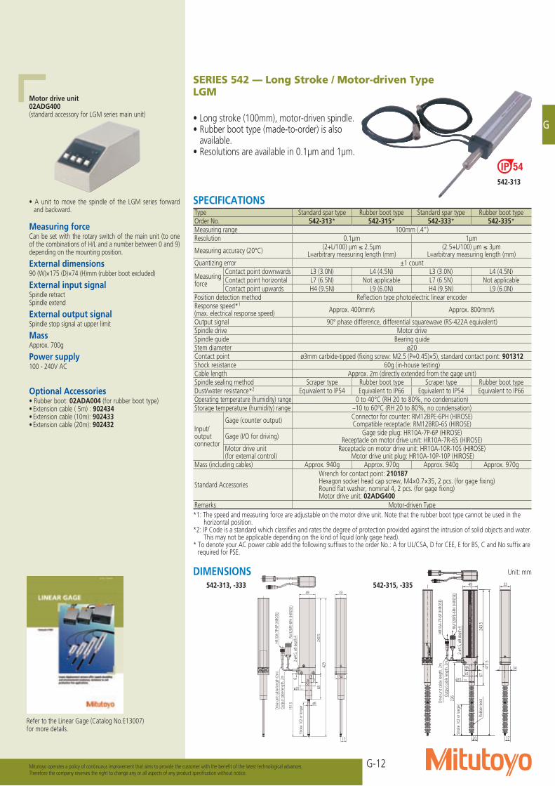
SERIES 542 — Long Stroke / Motor-driven TypeLGM
• Long stroke (100mm), motor-driven spindle.• Rubber boot type (made-to-order) is also
available.• Resolutions are available in 0.1μm and 1μm.
Outp
ut ca
ble
lengt
h, 2
mDr
ive u
nit c
able
lengt
h (2
m)
2-ø4
.5, ø
9 de
pth
4RM12
BPE-
6PH
(HIR
OSE)
HR10
A-7P
-6P
(HIR
OSE)
13
50–0.0130ø20
619
1.5
Stro
ke 1
02 o
r lon
ger ø6
429
17
34
49 33
736
243.
568
Motor drive unit02ADG400 (standard accessory for LGM series main unit)
• A unit to move the spindle of the LGM series forward and backward.
Measuring forceCan be set with the rotary switch of the main unit (to one of the combinations of H/L and a number between 0 and 9) depending on the mounting position.
External dimensions90 (W)×175 (D)×74 (H)mm (rubber boot excluded)
External input signalSpindle retractSpindle extend
External output signalSpindle stop signal at upper limit
MassApprox. 700g
Power supply100 - 240V AC
Optional Accessories• Rubber boot: 02ADA004 (for rubber boot type)• Extension cable ( 5m) : 902434• Extension cable (10m): 902433• Extension cable (20m): 902432
DIMENSIONS
542-313
542-313, -333 542-315, -335
Refer to the Linear Gage (Catalog No.E13007) for more details.
SPECIFICATIONSType Standard spar type Rubber boot type Standard spar type Rubber boot typeOrder No. 542-313* 542-315* 542-333* 542-335*Measuring range 100mm (.4”)Resolution 0.1μm 1μm
Measuring accuracy (20°C) (2+L/100) μm ≤ 2.5μm L=arbitrary measuring length (mm)
(2.5+L/100) μm ≤ 3μm L=arbitrary measuring length (mm)
Quantizing error ±1 count
Measuring force
Contact point downwards L3 (3.0N) L4 (4.5N) L3 (3.0N) L4 (4.5N)Contact point horizontal L7 (6.5N) Not applicable L7 (6.5N) Not applicableContact point upwards H4 (9.5N) L9 (6.0N) H4 (9.5N) L9 (6.0N)
Position detection method Reflection type photoelectric linear encoderResponse speed*1 (max. electrical response speed) Approx. 400mm/s Approx. 800mm/s
Output signal 90° phase difference, differential squarewave (RS-422A equivalent)Spindle drive Motor driveSpindle guide Bearing guideStem diameter ø20Contact point ø3mm carbide-tipped (fixing screw: M2.5 (P=0.45)×5), standard contact point: 901312Shock resistance 60g (in-house testing)Cable length Approx. 2m (directly extended from the gage unit)Spindle sealing method Scraper type Rubber boot type Scraper type Rubber boot typeDust/water resistance*2 Equivalent to IP54 Equivalent to IP66 Equivalent to IP54 Equivalent to IP66Operating temperature (humidity) range 0 to 40°C (RH 20 to 80%, no condensation)Storage temperature (humidity) range –10 to 60°C (RH 20 to 80%, no condensation)
Input/output connector
Gage (counter output) Connector for counter: RM12BPE-6PH (HIROSE)Compatible receptacle: RM12BRD-6S (HIROSE)
Gage (I/O for driving) Gage side plug: HR10A-7P-6P (HIROSE)Receptacle on motor drive unit: HR10A-7R-6S (HIROSE)
Motor drive unit (for external control)
Receptacle on motor drive unit: HR10A-10R-10S (HIROSE)Motor drive unit plug: HR10A-10P-10P (HIROSE)
Mass (including cables) Approx. 940g Approx. 970g Approx. 940g Approx. 970g
Standard Accessories
Wrench for contact point: 210187Hexagon socket head cap screw, M4×0.7×35, 2 pcs. (for gage fixing)Round flat washer, nominal 4, 2 pcs. (for gage fixing)Motor drive unit: 02ADG400
Remarks Motor-driven Type*1: The speed and measuring force are adjustable on the motor drive unit. Note that the rubber boot type cannot be used in the
horizontal position.*2: IP Code is a standard which classifies and rates the degree of protection provided against the intrusion of solid objects and water.
This may not be applicable depending on the kind of liquid (only gage head). * To denote your AC power cable add the following suffixes to the order No.: A for UL/CSA, D for CEE, E for BS, C and No suffix are
required for PSE.
G-13
G
Linear GageIdeal for integration into harsh environments such as automation applications
Mitutoyo operates a policy of continuous improvement that aims to provide the customer with the benefit of the latest technological advances.Therefore the company reserves the right to change any or all aspects of any product specification without notice.
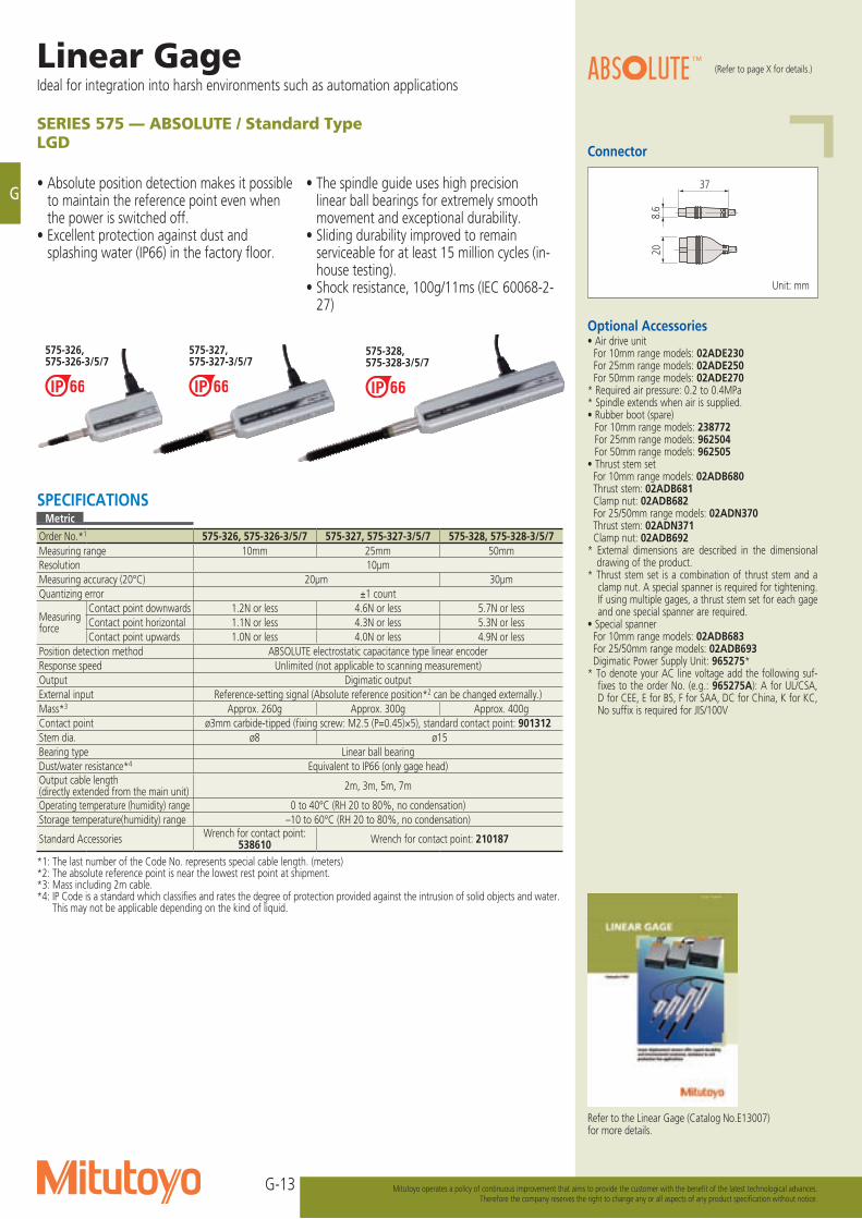
SERIES 575 — ABSOLUTE / Standard TypeLGD
• Absolute position detection makes it possible to maintain the reference point even when the power is switched off.
• Excellent protection against dust and splashing water (IP66) in the factory floor.
• The spindle guide uses high precision linear ball bearings for extremely smooth movement and exceptional durability.
• Sliding durability improved to remain serviceable for at least 15 million cycles (in-house testing).
• Shock resistance, 100g/11ms (IEC 60068-2-27)
Connector
37
8.6
20
Unit: mm
Optional Accessories• Air drive unit For 10mm range models: 02ADE230 For 25mm range models: 02ADE250 For 50mm range models: 02ADE270* Required air pressure: 0.2 to 0.4MPa* Spindle extends when air is supplied.• Rubber boot (spare) For 10mm range models: 238772 For 25mm range models: 962504 For 50mm range models: 962505• Thrust stem set For 10mm range models: 02ADB680 Thrust stem: 02ADB681 Clamp nut: 02ADB682 For 25/50mm range models: 02ADN370 Thrust stem: 02ADN371 Clamp nut: 02ADB692* External dimensions are described in the dimensional
drawing of the product.* Thrust stem set is a combination of thrust stem and a
clamp nut. A special spanner is required for tightening. If using multiple gages, a thrust stem set for each gage and one special spanner are required.
• Special spanner For 10mm range models: 02ADB683 For 25/50mm range models: 02ADB693 Digimatic Power Supply Unit: 965275** To denote your AC line voltage add the following suf-
fixes to the order No. (e.g.: 965275A): A for UL/CSA, D for CEE, E for BS, F for SAA, DC for China, K for KC, No suffix is required for JIS/100V
Refer to the Linear Gage (Catalog No.E13007) for more details.
575-326, 575-326-3/5/7
575-327, 575-327-3/5/7
575-328, 575-328-3/5/7
SPECIFICATIONSMetric
Order No.*1 575-326, 575-326-3/5/7 575-327, 575-327-3/5/7 575-328, 575-328-3/5/7Measuring range 10mm 25mm 50mmResolution 10μmMeasuring accuracy (20°C) 20μm 30μmQuantizing error ±1 count
Measuring force
Contact point downwards 1.2N or less 4.6N or less 5.7N or lessContact point horizontal 1.1N or less 4.3N or less 5.3N or lessContact point upwards 1.0N or less 4.0N or less 4.9N or less
Position detection method ABSOLUTE electrostatic capacitance type linear encoderResponse speed Unlimited (not applicable to scanning measurement)Output Digimatic outputExternal input Reference-setting signal (Absolute reference position*2 can be changed externally.)Mass*3 Approx. 260g Approx. 300g Approx. 400gContact point ø3mm carbide-tipped (fixing screw: M2.5 (P=0.45)×5), standard contact point: 901312Stem dia. ø8 ø15Bearing type Linear ball bearingDust/water resistance*4 Equivalent to IP66 (only gage head)Output cable length (directly extended from the main unit) 2m, 3m, 5m, 7m
Operating temperature (humidity) range 0 to 40°C (RH 20 to 80%, no condensation)Storage temperature(humidity) range –10 to 60°C (RH 20 to 80%, no condensation)
Standard Accessories Wrench for contact point: 538610 Wrench for contact point: 210187
*1: The last number of the Code No. represents special cable length. (meters)*2: The absolute reference point is near the lowest rest point at shipment.*3: Mass including 2m cable. *4: IP Code is a standard which classifies and rates the degree of protection provided against the intrusion of solid objects and water.
This may not be applicable depending on the kind of liquid.
(Refer to page X for details.)
G-14
G
Mitutoyo operates a policy of continuous improvement that aims to provide the customer with the benefit of the latest technological advances.Therefore the company reserves the right to change any or all aspects of any product specification without notice.
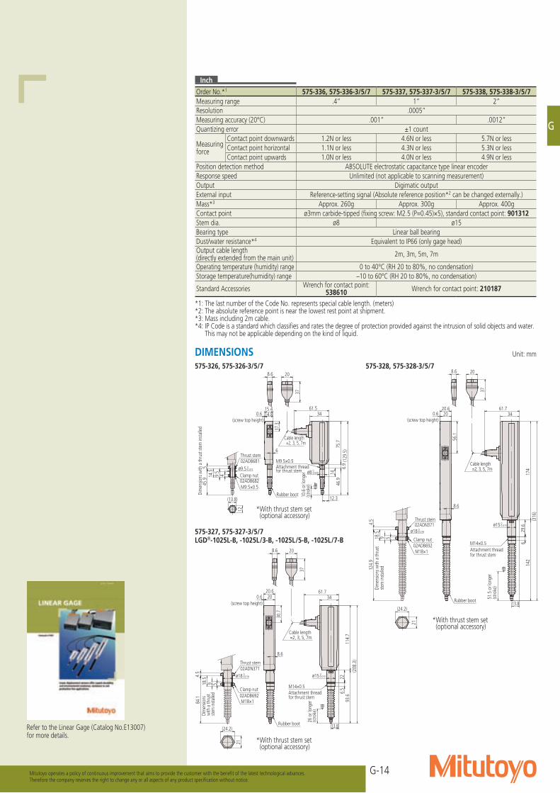
575-326, 575-326-3/5/7 575-328, 575-328-3/5/7
575-327, 575-327-3/5/7LGD®-1025L-B, -1025L/3-B, -1025L/5-B, -1025L/7-B
Dim
ensio
ns w
ith a
thru
st ste
m in
stalle
d
Cable length =2, 3, 5, 7m
(screw top height)
02ADB681Thrust stem
02ADB682Clamp nut
M9.5×0.5Attachment thread for thrust stem
M9.5×0.5
46.9
61.515.4
(129
.5)
34
10.6
or l
onge
r (st
roke
)
12.3
ø8-0.009 0
17.3
20
37
8.6
6
9.5
14.5
4
ø9.5-0.015 0
(13.8)
12
545
.9
75.7
14
6.9
14.80.6
Rubber boot
Attachment thread for thrust stem
M14×0.5
(screw top height)
Cable length =2, 3, 5, 7m
26 o
r lon
ger
(stro
ke)
02ADB692
02ADN371
Clamp nut
Thrust stem
M18×1
Dim
ensio
ns
with
a th
rust
stem
insta
lled
18.5
9 5
ø18-0.018 0
(24.2)
21
93.6
8.6
34
(208
.3)
13.8
ø15-0.015 0
20
37
8.6
61.7
30.7
20.6
4.5
84.1
200.6
114.
76.
522
Rubber boot
Dim
ensio
ns w
ith a
thru
st ste
m in
stalle
d
(screw top height)
Cable length =2, 3, 5, 7m
51.5
or l
onge
r (st
roke
)
M14×0.5Attachment thread for thrust stem
M18×1
Thrust stem
Clamp nut
02ADN371
02ADB692
18.5
9 5
ø18-0.018 0
(24.2)
21
142
34
13.8
(316
)
0.6
ø15-0.015 0
37
208.6
61.720.6
56.1
8.6
4.5
124.
9
174
629
.6
20
Rubber boot
Refer to the Linear Gage (Catalog No.E13007) for more details.
Inch
Order No.*1 575-336, 575-336-3/5/7 575-337, 575-337-3/5/7 575-338, 575-338-3/5/7Measuring range .4” 1” 2”Resolution .0005”Measuring accuracy (20°C) .001” .0012”Quantizing error ±1 count
Measuring force
Contact point downwards 1.2N or less 4.6N or less 5.7N or lessContact point horizontal 1.1N or less 4.3N or less 5.3N or lessContact point upwards 1.0N or less 4.0N or less 4.9N or less
Position detection method ABSOLUTE electrostatic capacitance type linear encoderResponse speed Unlimited (not applicable to scanning measurement)Output Digimatic outputExternal input Reference-setting signal (Absolute reference position*2 can be changed externally.)Mass*3 Approx. 260g Approx. 300g Approx. 400gContact point ø3mm carbide-tipped (fixing screw: M2.5 (P=0.45)×5), standard contact point: 901312Stem dia. ø8 ø15Bearing type Linear ball bearingDust/water resistance*4 Equivalent to IP66 (only gage head)Output cable length (directly extended from the main unit) 2m, 3m, 5m, 7m
Operating temperature (humidity) range 0 to 40°C (RH 20 to 80%, no condensation)Storage temperature(humidity) range –10 to 60°C (RH 20 to 80%, no condensation)
Standard Accessories Wrench for contact point: 538610 Wrench for contact point: 210187
*1: The last number of the Code No. represents special cable length. (meters)*2: The absolute reference point is near the lowest rest point at shipment.*3: Mass including 2m cable. *4: IP Code is a standard which classifies and rates the degree of protection provided against the intrusion of solid objects and water.
This may not be applicable depending on the kind of liquid.
Unit: mmDIMENSIONS
*With thrust stem set (optional accessory)
*With thrust stem set (optional accessory)
*With thrust stem set (optional accessory)
G-15
G
Linear GageIdeal for integration into harsh environments such as automation applications
Mitutoyo operates a policy of continuous improvement that aims to provide the customer with the benefit of the latest technological advances.Therefore the company reserves the right to change any or all aspects of any product specification without notice.
Unit: inchUnit: mm
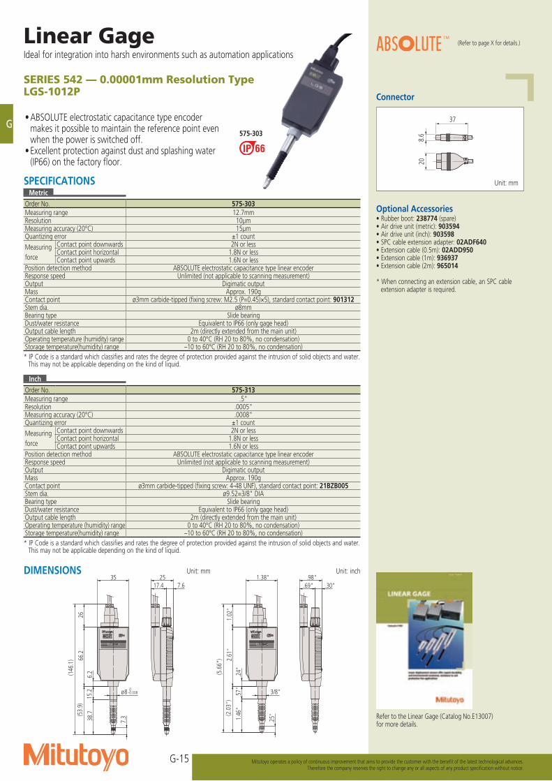
SERIES 542 — 0.00001mm Resolution TypeLGS-1012P
• ABSOLUTE electrostatic capacitance type encoder makes it possible to maintain the reference point even when the power is switched off.
• Excellent protection against dust and splashing water (IP66) on the factory floor.
575-303
DIMENSIONS
Optional Accessories• Rubber boot: 238774 (spare)• Air drive unit (metric): 903594• Air drive unit (inch): 903598• SPC cable extension adapter: 02ADF640• Extension cable (0.5m): 02ADD950• Extension cable (1m): 936937• Extension cable (2m): 965014
* When connecting an extension cable, an SPC cable extension adapter is required.
Connector
37
8.6
20
SPECIFICATIONSMetric
Order No. 575-303Measuring range 12.7mmResolution 10μmMeasuring accuracy (20°C) 15μmQuantizing error ±1 countMeasuring force
Contact point downwards 2N or lessContact point horizontal 1.8N or lessContact point upwards 1.6N or less
Position detection method ABSOLUTE electrostatic capacitance type linear encoderResponse speed Unlimited (not applicable to scanning measurement)Output Digimatic outputMass Approx. 190gContact point ø3mm carbide-tipped (fixing screw: M2.5 (P=0.45)×5), standard contact point: 901312Stem dia. ø8mmBearing type Slide bearingDust/water resistance Equivalent to IP66 (only gage head)Output cable length 2m (directly extended from the main unit)Operating temperature (humidity) range 0 to 40°C (RH 20 to 80%, no condensation)Storage temperature(humidity) range –10 to 60°C (RH 20 to 80%, no condensation)* IP Code is a standard which classifies and rates the degree of protection provided against the intrusion of solid objects and water.
This may not be applicable depending on the kind of liquid.
Inch
Order No. 575-313Measuring range .5"Resolution .0005"Measuring accuracy (20°C) .0008"Quantizing error ±1 countMeasuring force
Contact point downwards 2N or lessContact point horizontal 1.8N or lessContact point upwards 1.6N or less
Position detection method ABSOLUTE electrostatic capacitance type linear encoderResponse speed Unlimited (not applicable to scanning measurement)Output Digimatic outputMass Approx. 190gContact point ø3mm carbide-tipped (fixing screw: 4-48 UNF), standard contact point: 21BZB005Stem dia. ø9.52=3/8" DIABearing type Slide bearingDust/water resistance Equivalent to IP66 (only gage head)Output cable length 2m (directly extended from the main unit)Operating temperature (humidity) range 0 to 40°C (RH 20 to 80%, no condensation)Storage temperature(humidity) range –10 to 60°C (RH 20 to 80%, no condensation)* IP Code is a standard which classifies and rates the degree of protection provided against the intrusion of solid objects and water.
This may not be applicable depending on the kind of liquid.
Unit: mm
Refer to the Linear Gage (Catalog No.E13007) for more details.
(Refer to page X for details.)
Unit : inchUnit : mm 575-313575-303
3/8"
.25"
(5.6
6")
(2.0
3")
1.46
".5
7"2.
61"
1.02
"
.98".30".69"
1.38"
.24"
357.617.4
25
7.3
(146
.1)
26(5
3.9)
66.2
6.2
15.2
38.7
ø8 0-0.008

G-16
G
Mitutoyo operates a policy of continuous improvement that aims to provide the customer with the benefit of the latest technological advances.Therefore the company reserves the right to change any or all aspects of any product specification without notice.
542-181
Unit: mm
Linear Gage SERIES 542 — Economical DesignLGF (0.1μm resolution)
• 0.1μm resolution type of reliable LGF series gage.
• Excellent protection against dust and splashing water (IP66) on the factory floor.
542-182
30
82.7
20.4
DIMENSIONS
Connector
RM12BPE-6PH (HIROSE) Unit: mm
(screw top height)
10.6
or lo
nger
(stro
ke)
Cable length, 2m
Dim
ensio
ns w
ith a
thru
st ste
m in
stalle
d
M9.5×0.5
Attachment thread for thrust stem
M9.5×0.5
Clamp nut02ADB682
Thrust stem02ADB681
6
17.3
ø8-0.009 0
12.3
34
(129
.5)
61.5
46.9
15.4
82.7
12
(13.8)
ø9.5-0.015 0
414.5 9.5
14.80.6
75.7
14
6.95
45.9
20.4 30
Rubber boot
26 o
r lon
ger
(stro
ke)
Cable length, 2m
(screw top height)
M14×0.5Attachment thread for thrust stem
Dim
ensio
ns w
ith a
thru
st ste
m in
stalle
d
M18×1
Thrust stem
Clamp nut
02ADN371
02ADB692
21
(24.2)
ø18-0.018 0
5918.5
20.6
30.7
61.7
15-0.015 0
13.8
(208
.3)
34
8.6
93.6
82.7
114.
76.
522
200.6
4.5
84.1
20.4 30
Rubber boot
Optional Accessories• Rubber boot (spare) For 10mm range models: 238772 For 25mm range models: 962504 For 50mm range models: 962505• Thrust stem set For 10mm range models: 02ADB680 Thrust stem: 02ADB681 Clamp nut: 02ADB682 For 25mm range models: 02ADN370 Thrust stem: 02ADN371 Clamp nut: 02ADB692* External dimensions are described in the dimensional
drawing of the product.* Thrust stem set is a combination of thrust stem and a
clamp nut. A special spanner is required for tightening. If using multiple gages, a thrust stem set for each gage and one special spanner are required.
• Special spanner For 10mm range models: 02ADB683 For 25mm range models: 02ADB693• Extension cable (5m): 902434• Extension cable (10m): 902433• Extension cable (20m): 902432
Refer to the Linear Gage (Catalog No.E13007) for more details.
SPECIFICATIONSOrder No. 542-181 542-182Measuring range 10mm (.4") 25mm (1")Resolution 0.1μmMeasuring accuracy (20°C) (0.8+L/50) μm (L=arbitrary measuring length (mm))Quantizing error ±1 count
Measuring force
Contact point downwards 1.2N or less 4.6N or lessContact point horizontal 1.1N or less 4.3N or lessContact point upwards 1.0N or less 4.0N or less
Position detection method Photoelectric linear encoderResponse speed*1 400mm/s
Output signal 90° phase difference, differential squarewave (RS-422A equivalent)Minimum edge-to-edge interval, 200ns
Output signal pitch 0.4μmMass Approx. 310g Approx. 350gDust/water resistance*2 Equivalent to IP66 (only gage head)Contact point ø3mm carbide-tipped (fixing screw: M2.5 (P=0.45)×5), standard contact point: 901312Stem dia. ø8 ø15Bearing type Linear ball bearingOutput cable length 2m (directly extended from the main unit)Connector Plug: RM12BPE-6PH (HIROSE), Compatible receptacle: RM12BRD-6S (HIROSE)Operating temperature (humidity) range 0 to 40°C (RH 20 to 80%, no condensation)Storage temperature(humidity) range –10 to 60°C (RH 20 to 80%, no condensation)Standard Accessories Wrench for contact point: 538610 Wrench for contact point: 210187
*1: When the spindle speed exceeds 400mm/s, an alarm signal will be output. Also, if using a Mitutoyo counter, an error message will be displayed. If using counters made by other companies, please consult your local Mitutoyo office. Note that over-speed error may occur depending on the impact amount when releasing the contact point freely.
*2: IP Code is a standard which classifies and rates the degree of protection provided against the intrusion of solid objects and water. This may not be applicable depending on the kind of liquid.
542-181 542-182
*With thrust stem set (optional accessory)
*With thrust stem set (optional accessory)
G-17
G
Linear GageIdeal for integration into harsh environments such as automation applications
Mitutoyo operates a policy of continuous improvement that aims to provide the customer with the benefit of the latest technological advances.Therefore the company reserves the right to change any or all aspects of any product specification without notice.
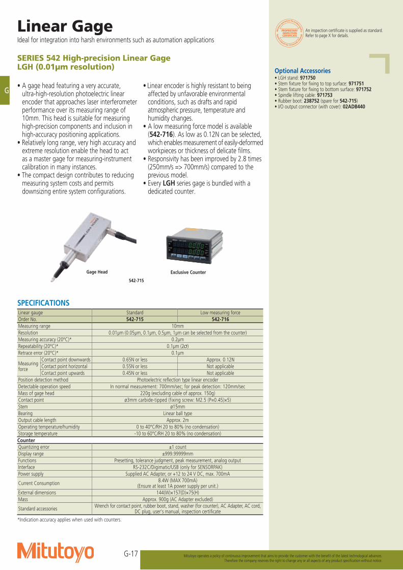
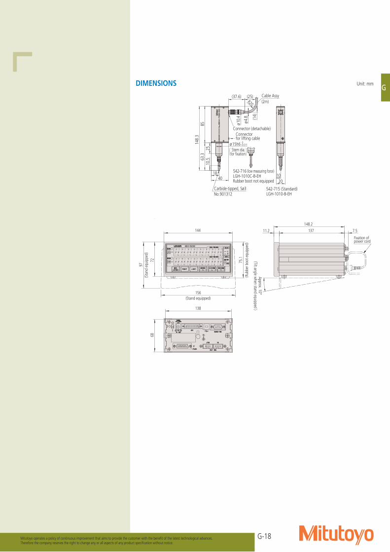
SERIES 542 High-precision Linear GageLGH (0.01μm resolution)
• A gage head featuring a very accurate, ultra-high-resolution photoelectric linear encoder that approaches laser interferometer performance over its measuring range of 10mm. This head is suitable for measuring high-precision components and inclusion in high-accuracy positioning applications.
• Relatively long range, very high accuracy and extreme resolution enable the head to act as a master gage for measuring-instrument calibration in many instances.
• The compact design contributes to reducing measuring system costs and permits downsizing entire system configurations.
• Linear encoder is highly resistant to being affected by unfavorable environmental conditions, such as drafts and rapid atmospheric pressure, temperature and humidity changes.
• A low measuring force model is available (542-716). As low as 0.12N can be selected, which enables measurement of easily-deformed workpieces or thickness of delicate films.
• Responsivity has been improved by 2.8 times (250mm/s => 700mm/s) compared to the previous model.
• Every LGH series gage is bundled with a dedicated counter.
Optional Accessories• LGH stand: 971750• Stem fixture for fixing to top surface: 971751• Stem fixture for fixing to bottom surface: 971752• Spindle lifting cable: 971753• Rubber boot: 238752 (spare for 542-715)• I/O output connector (with cover): 02ADB440
SPECIFICATIONSLinear gauge Standard Low measuring forceOrder No. 542-715 542-716Measuring range 10mmResolution 0.01μm (0.05μm, 0.1μm, 0.5μm, 1μm can be selected from the counter)Measuring accuracy (20°C)* 0.2μmRepeatability (20°C)* 0.1μm (2σ)Retrace error (20°C)* 0.1μm
Measuring force
Contact point downwards 0.65N or less Approx. 0.12NContact point horizontal 0.55N or less Not applicableContact point upwards 0.45N or less Not applicable
Position detection method Photoelectric reflection type linear encoderDetectable operation speed In normal measurement: 700mm/sec; for peak detection: 120mm/secMass of gage head 220g (excluding cable of approx. 150g)Contact point ø3mm carbide-tipped (fixing screw: M2.5 (P=0.45)×5)Stem ø15mmBearing Linear ball typeOutput cable length Approx. 2mOperating temperature/humidity 0 to 40°C/RH 20 to 80% (no condensation)Storage temperature -10 to 60°C/RH 20 to 80% (no condensation)Counter Quantizing error ±1 countDisplay range ±999.99999mmFunctions Presetting, tolerance judgment, peak measurement, analog outputInterface RS-232C/Digimatic/USB (only for SENSORPAK)Power supply Supplied AC Adapter, or +12 to 24 V DC, max. 700mA
Current Consumption 8.4W (MAX 700mA)(Ensure at least 1A power supply per unit.)
External dimensions 144(W)×157(D)×75(H)Mass Approx. 900g (AC Adapter excluded)
Standard accessories Wrench for contact point, rubber boot, stand, washer (for counter), AC Adapter, AC cord, DC plug, user's manual, inspection certificate
*Indication accuracy applies when used with counters.
Gage Head
542-715
Exclusive Counter
An inspection certificate is supplied as standard. Refer to page X for details.
G-18
G
Mitutoyo operates a policy of continuous improvement that aims to provide the customer with the benefit of the latest technological advances.Therefore the company reserves the right to change any or all aspects of any product specification without notice.
Cable Assy(2m)
Connector (detachable)
Stem dia. for fixation( )
Carbide-tipped, Sø3No.901312
Connector for lifting cable
542-716 (low measuring force)LGH-1010C-B-EHRubber boot not equipped
542-715 (Standard)LGH-1010-B-EH
(37.6) (25)
ø4.8
ø10.
4
10.563
.3
ø15h6 0-0.011
4018
2010
148.
3
(14)
8525
R20
Unit: mmDIMENSIONS
IN
DC IN
INPUT
A
700mA
I/ORS-232C
OUT
RS LINK
DC12-24V
B
Code No. 542-***Model EH-12SSerial No. 000001
MADE IN JAPAN
43 12
27
11.2
137
5.1
137
156.7
144
72(3
.1)
68
138
148.2
Fixation of power cord
(Approx. 10°)Approx. 10°
(Tilt angle when stand equipped )
144
148.
2
11.2
137
7.5
138
68
156(Stand equipped)
72
97(S
tand
equ
ippe
d)
75.1
(Rub
ber b
oot e
quip
ped)
148.2
11.2 137 7.5
G-19
G
Linear GageIdeal for integration into harsh environments such as automation applications
Mitutoyo operates a policy of continuous improvement that aims to provide the customer with the benefit of the latest technological advances.Therefore the company reserves the right to change any or all aspects of any product specification without notice.
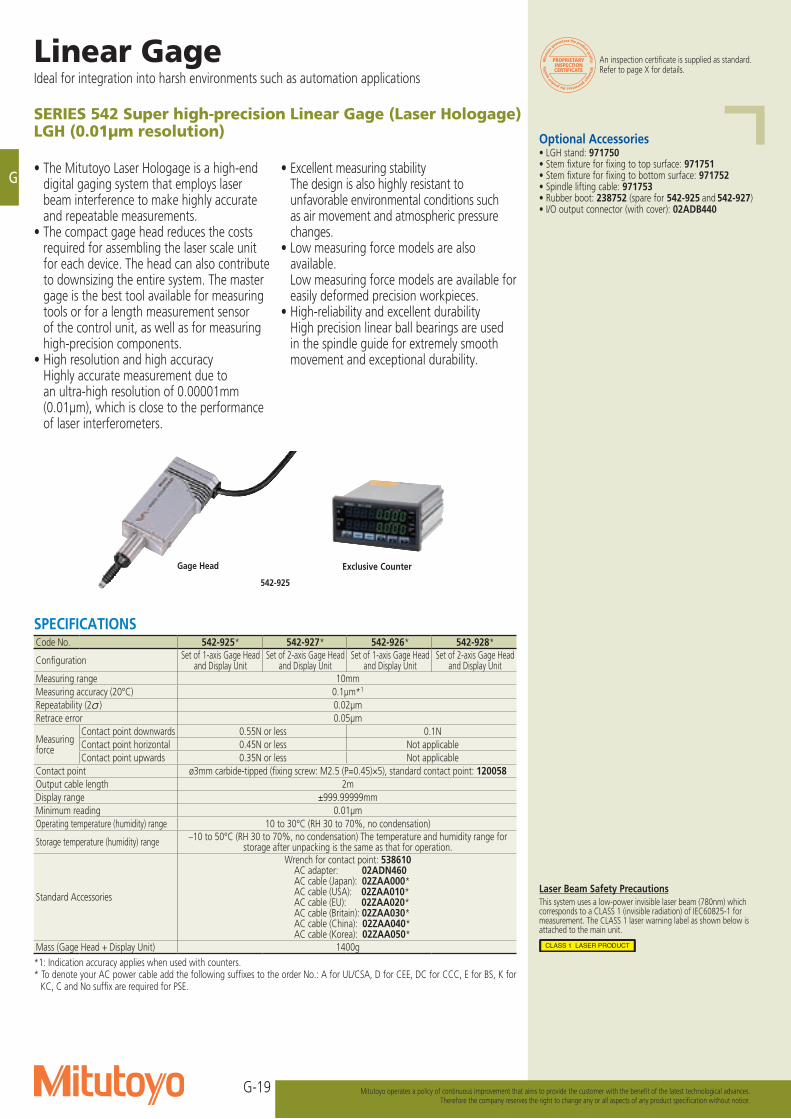
• Excellent measuring stability The design is also highly resistant to
unfavorable environmental conditions such as air movement and atmospheric pressure changes.
• Low measuring force models are also available.
Low measuring force models are available for easily deformed precision workpieces.
• High-reliability and excellent durability High precision linear ball bearings are used
in the spindle guide for extremely smooth movement and exceptional durability.
SERIES 542 Super high-precision Linear Gage (Laser Hologage)LGH (0.01μm resolution)
• The Mitutoyo Laser Hologage is a high-end digital gaging system that employs laser beam interference to make highly accurate and repeatable measurements.
• The compact gage head reduces the costs required for assembling the laser scale unit for each device. The head can also contribute to downsizing the entire system. The master gage is the best tool available for measuring tools or for a length measurement sensor of the control unit, as well as for measuring high-precision components.
• High resolution and high accuracy Highly accurate measurement due to
an ultra-high resolution of 0.00001mm (0.01μm), which is close to the performance of laser interferometers.
Optional Accessories• LGH stand: 971750• Stem fixture for fixing to top surface: 971751• Stem fixture for fixing to bottom surface: 971752• Spindle lifting cable: 971753• Rubber boot: 238752 (spare for 542-925 and 542-927)• I/O output connector (with cover): 02ADB440
SPECIFICATIONSCode No. 542-925* 542-927* 542-926* 542-928*
Configuration Set of 1-axis Gage Head and Display Unit
Set of 2-axis Gage Head and Display Unit
Set of 1-axis Gage Head and Display Unit
Set of 2-axis Gage Head and Display Unit
Measuring range 10mmMeasuring accuracy (20°C) 0.1μm*1
Repeatability (2 ) 0.02μmRetrace error 0.05μm
Measuringforce
Contact point downwards 0.55N or less 0.1NContact point horizontal 0.45N or less Not applicableContact point upwards 0.35N or less Not applicable
Contact point ø3mm carbide-tipped (fixing screw: M2.5 (P=0.45)×5), standard contact point: 120058Output cable length 2mDisplay range ±999.99999mmMinimum reading 0.01μmOperating temperature (humidity) range 10 to 30°C (RH 30 to 70%, no condensation)
Storage temperature (humidity) range –10 to 50°C (RH 30 to 70%, no condensation) The temperature and humidity range for storage after unpacking is the same as that for operation.
Standard Accessories
Wrench for contact point: 538610AC adapter: 02ADN460AC cable (Japan): 02ZAA000*AC cable (USA): 02ZAA010*AC cable (EU): 02ZAA020*AC cable (Britain): 02ZAA030*AC cable (China): 02ZAA040*AC cable (Korea): 02ZAA050*
Mass (Gage Head + Display Unit) 1400g*1: Indication accuracy applies when used with counters.* To denote your AC power cable add the following suffixes to the order No.: A for UL/CSA, D for CEE, DC for CCC, E for BS, K for
KC, C and No suffix are required for PSE.
Laser Beam Safety PrecautionsThis system uses a low-power invisible laser beam (780nm) which corresponds to a CLASS 1 (invisible radiation) of IEC60825-1 for measurement. The CLASS 1 laser warning label as shown below is attached to the main unit.
An inspection certificate is supplied as standard. Refer to page X for details.
Gage Head
542-925
Exclusive Counter
G-20
G
Mitutoyo operates a policy of continuous improvement that aims to provide the customer with the benefit of the latest technological advances.Therefore the company reserves the right to change any or all aspects of any product specification without notice.
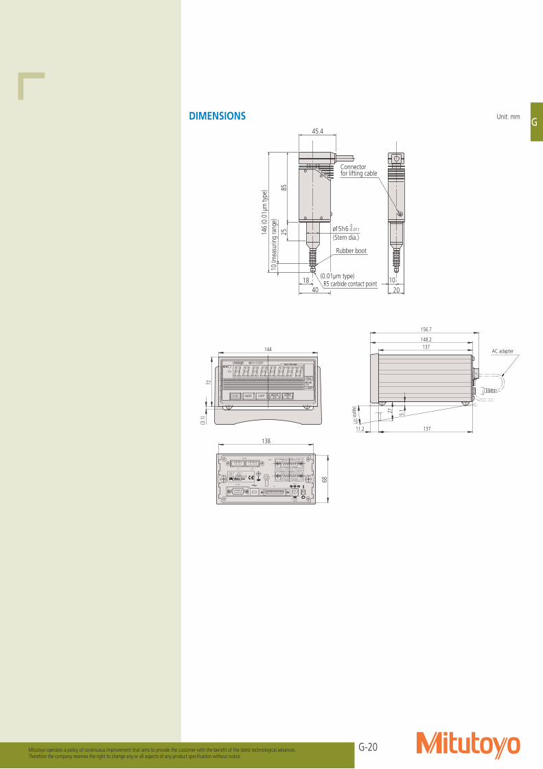
45.4
Connector for lifting cable
85
146
(0.0
1µm
type
)
2510
(mea
surin
g ra
nge)
1020
ø15h6
1840
(Stem dia.)
(0.01µm type) R5 carbide contact point
0-0.011
Rubber boot
2134
MADE IN JAPANSerial No. 000001Model EH-12SCode No. 542-***B
DC12-24V
RS LINK
OUT
RS-232C I/O
700mA
AINPUT
DC IN
DC IN
700mA
I/ORS-232C
OUT
RS LINK
DC12-24V4312
MADE IN JAPANSerial No. 000001Model EH-12PCode No. 542-***
B AINPUT
2134
MADE IN JAPANSerial No. 000001Model EH-12ZCode No. 542-***
DC12-24V
RS LINK
OUT
RS-232C I/O
700mA
DC IN
B AINPUT
IN
DC IN
INPUT
A
700mA
I/ORS-232C
OUT
RS LINK
DC12-24V
B
Code No. 542-***Model EH-12SSerial No. 000001
MADE IN JAPAN
4312
DC IN
700mA
I/ORS-232C
OUT
RS LINK
DC12-24V
Code No. 542-***Model EH-12PSerial No. 000001MADE IN JAPAN
4312
INPUTAB
27
11.2
137
5.1
137
156.7
68
138
68
138
68
138
144
72(3
.1)
68
138
148.2
68
144
138
AC adapter
(Approx.10º)
Unit: mmDIMENSIONS
G-21
G
Linear GageIdeal for integration into harsh environments such as automation applications
Mitutoyo operates a policy of continuous improvement that aims to provide the customer with the benefit of the latest technological advances.Therefore the company reserves the right to change any or all aspects of any product specification without notice.
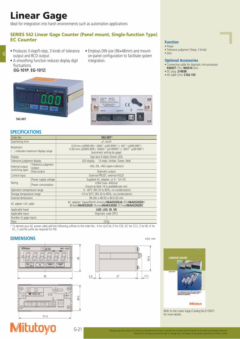
SERIES 542 Linear Gage Counter (Panel mount, Single-function Type)EC Counter
• Produces 3-step/5-step, 3 kinds of tolerance output and BCD output.
• A smoothing function reduces display digit fluctuations.
(EG-101P, EG-101Z)
• Employs DIN size (96×48mm) and mount-on-panel configuration to facilitate system integration.
000001EC-101D542-007
Serial No.ModelCode No.
48
96 6.6 67 (11)
44.4
91.4
44.
4
542-007
Function• Preset• Tolerance judgment (3step, 3 kinds)• Zero
Optional Accessories• Connecting cable for digimatic mini-processor: 936937 (1m), 965014 (2m)• DC plug: 214938• I/O cable (2m): C162-155
Refer to the Linear Gage (Catalog No.E13007) for more details.
Unit: mmDIMENSIONS
SPECIFICATIONSOrder No. 542-007*Quantizing error ±1 count
Resolution( ) indicates maximum display range
0.01mm (±9999.99) / .0005" (±99.9995") / .001" (±999.999")0.001mm (±9999.999) / .00005" (±9.99995") / .0001" (±99.999")
[automatic setting by gage]Display Sign plus 6 digits (Green LED)Tolerance judgment display LED display (3 steps: Amber, Green, Red)
External output (switching type)
Tolerance judgment output –NG, OK, +NG (open-collector)
Data output Digimatic outputControl input External PRESET, external HOLD
RatingPower supply voltage Supplied AC adapter, or 9 - 12V DC
Power consumption 4.8W (max. 400mA)Ensure at least 1A is available per unit.
Operation temperature range 0 - 40°C (RH 20 to 80%, no condensation)Storage temperature range –10 to 50°C (RH 20 to 80%, no condensation)External dimensions 96 (W) × 48 (H) × 84.6 (D) mm
AC adpter / AC cable AC adapter: (Japan/North America)06AEG302JA /(EU)06AEG302D /(Britain)06AEG302E /(Korea)06AEG302K /(China)06AEG302DC
Applicable head LGD, LGS, ID, SDApplicable input Digimatic code (SPC)Number of gage inputs 1Mass 220g* To denote your AC power cable add the following suffixes to the order No.: A for UL/CSA, D for CEE, DC for CCC, E for BS, K for
KC, C and No suffix are required for PSE.
G-22
G
Mitutoyo operates a policy of continuous improvement that aims to provide the customer with the benefit of the latest technological advances.Therefore the company reserves the right to change any or all aspects of any product specification without notice.
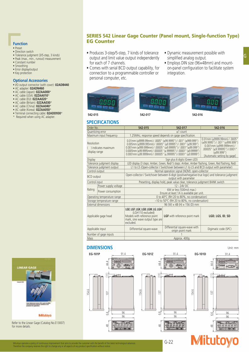
SERIES 542 Linear Gage Counter (Panel mount, Single-function Type)EG Counter
• Produces 3-step/5-step, 7 kinds of tolerance output and limit value output independently for each of 7 channels.
• Comes with serial BCD output capability, for connection to a programmable controller or personal computer, etc.
• Dynamic measurement possible with simplified analog output.
• Employs DIN size (96×48mm) and mount-on-panel configuration to facilitate system integration.
Function• Preset• Direction switch• Tolerance judgment (3/5-step, 3 kinds)• Peak (max., min., runout) measurement• Constant number• Smoothing• Error display/output• Key protection
Optional Accessories• I/O output connector (with cover): 02ADB440• AC adapter: 02ADN460• AC cable (Japan): 02ZAA000*• AC cable (USA): 02ZAA010*• AC cable (EU): 02ZAA020*• AC cable (Britain): 02ZAA030*• AC cable (China): 02ZAA040*• AC cable (Korea): 02ZAA050*• Terminal connecting cable: 02ADD930** Required when using AC adapter.
EG-101P EG-101Z EG-101D
542-015 542-017 542-016
Refer to the Linear Gage (Catalog No.E13007) for more details.
SPECIFICATIONSOrder No. 542-015 542-017 542-016Quantizing error ±1 countMaximum input frequency 1.25MHz, response speed depends on gage specification. —
Resolution( ) indicates maximum display range
0.01mm (±9999.99mm) / .0005" (±99.9995") / .001" (±999.999")0.005mm (±9999.995mm) / .00005" (±9.99995") / .0001" (±99.999")
0.001mm (±999.999mm) / .00005" (±9.99995") / .0001"(±99.999")0.0005mm (±99.9995mm) / .000005" (±.999995") / .00001" (±9.99999")0.0001mm (±99.9999mm) / .000005" (±.999995") /.00001" (±9.99999")
0.01mm (±9999.99mm) / .0005" (±99.9995") / .001" (±999.999")
0.001mm (±999.999mm) / .00005" (±9.99995") /.0001"
(±99.999") [Automatic setting by gage]
Display Sign plus 6 digits (Green LED)Tolerance judgment display LED display (3 steps: Amber, Green, Red/ 5 steps: Amber, Amber flashing, Green, Red flashing, Red)Tolerance judgment output L1 to L5 (Open-collector / Switchover between L1 to L5 and BCD output with parameter)Control output Normal operation signal (NOM): open-collector
BCD output Open-collector / Switchover between 6-digit (positive/negative-true logic) and tolerance judgment output with parameter
Control input Presetting, display hold, peak value clear, tolerance judgment BANK switch
RatingPower supply voltage 12 - 24V DC
Power consumption 6W or less (500mA max.)Ensure at least 1A is available per unit.
Operating temperature range 0 to 40°C (RH 20 to 80%, no condensation)Storage temperature range –10 to 50°C (RH 20 to 80%, no condensation)External dimensions 96 (W) × 48 (H) × 156 (D) mm
Applicable gage head
LGE, LGF, LGK, LGB, LGM, LG, LGH (LGH110 excluded)
Models with reference point mark, sine wave output type are excluded.
LGF with reference point mark LGD, LGS, ID, SD
Applicable input Differential square-wave Differential square-wave with origin point mark Digimatic code (SPC)
Number of gage inputs 1Mass Approx. 400g
Unit: mmDIMENSIONS
+V
DC IN 12-24V 500mA
-V OUTPUT
INPUT
154.
6
48
96966.
613
7(
11)
91.4
44.4
154.
6
48
96966.
613
7(
11)
91.4
44.4
INPUT
OUTPUT-V
DC IN 12-24V 500mA
+V
154.
6
48
96966.
613
7(
11)
91.4
44.4
INPUT
DC IN 12-24V 500mA
**********-***
******Serial No.ModelCode No.
G-23
G
Linear GageIdeal for integration into harsh environments such as automation applications
Mitutoyo operates a policy of continuous improvement that aims to provide the customer with the benefit of the latest technological advances.Therefore the company reserves the right to change any or all aspects of any product specification without notice.
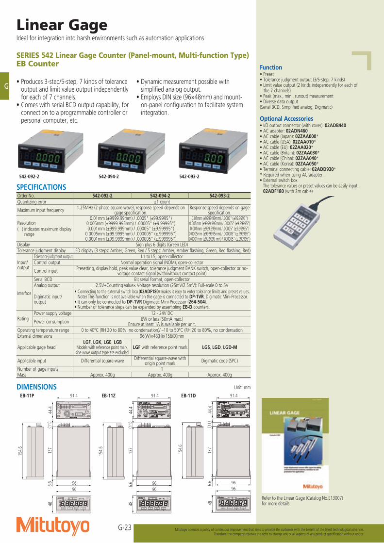
SERIES 542 Linear Gage Counter (Panel-mount, Multi-function Type)EB Counter
• Produces 3-step/5-step, 7 kinds of tolerance output and limit value output independently for each of 7 channels.
• Comes with serial BCD output capability, for connection to a programmable controller or personal computer, etc.
• Dynamic measurement possible with simplified analog output.
• Employs DIN size (96×48mm) and mount-on-panel configuration to facilitate system integration.
542-092-2 542-094-2 542-093-2
EB-11ZEB-11P EB-11D
Function• Preset• Tolerance judgment output (3/5-step, 7 kinds)• Limit value output (2 kinds independently for each of
the 7 channels)• Peak (max., min., runout) measurement• Diverse data output(Serial BCD, Simplified analog, Digimatic)
Optional Accessories• I/O output connector (with cover): 02ADB440• AC adapter: 02ADN460• AC cable (Japan): 02ZAA000*• AC cable (USA): 02ZAA010*• AC cable (EU): 02ZAA020*• AC cable (Britain): 02ZAA030*• AC cable (China): 02ZAA040*• AC cable (Korea): 02ZAA050*• Terminal connecting cable: 02ADD930** Required when using AC adapter.• External switch box The tolerance values or preset values can be easily input. 02ADF180 (with 2m cable)
Refer to the Linear Gage (Catalog No.E13007) for more details.
SPECIFICATIONSOrder No. 542-092-2 542-094-2 542-093-2Quantizing error ±1 count
Maximum input frequency 1.25MHz (2-phase square wave), response speed depends on gage specification.
Response speed depends on gage specification.
Resolution( ) indicates maximum display
range
0.01mm (±9999.99mm) / .0005" (±99.9995")0.005mm (±9999.995mm) / .00005" (±9.99995")0.001mm (±999.999mm) / .00005" (±9.99995")
0.0005mm (±99.9995mm) / .000005" (±.999995")0.0001mm (±99.9999mm) / .000005" (±.999995")
0.01mm (±9999.99mm) / .0005" (±99.9995")0.005mm (±9999.995mm) / .00005" (±9.99995")0.001mm (±999.999mm) / .00005" (±9.99995")
0.0005mm (±99.9995mm) / .000005" (±.999995")0.0001mm (±99.9999 mm) / .000005" (±.999995")
Display Sign plus 6 digits (Green LED)Tolerance judgment display LED display (3 steps: Amber, Green, Red / 5 steps: Amber, Amber flashing, Green, Red flashing, Red)
Input/output
Tolerance judgment output L1 to L5, open-collectorControl output Normal operation signal (NOM), open-collector
Control input Presetting, display hold, peak value clear, tolerance judgment BANK switch, open-collector or no-voltage contact signal (with/without contact point)
Interface
Serial BCD Bit serial format, open-collectorAnalog output 2.5V+Counting value× Voltage resolution (25mV/2.5mV): Full-scale 0 to 5V
Digimatic input/output
• Connecting to the external switch box (02ADF180) makes it easy to enter tolerance limits and preset values. Note) This function is not available when the gage is connected to DP-1VR, Digimatic Mini-Processor. • It can only be connected to DP-1VR Digimatic Mini-Processor (264-504). • Number of tolerance steps can be expanded by assembling EB-D counters.
RatingPower supply voltage 12 - 24V DC
Power consumption 6W or less (50mA max.)Ensure at least 1A is available per unit.
Operating temperature range 0 to 40°C (RH 20 to 80%, no condensation)/ –10 to 50°C (RH 20 to 80%, no condensationExternal dimensions 96(W)×48(H)×156(D)mm
Applicable gage headLGF, LGK, LGE, LGB
Models with reference point mark, sine wave output type are excluded.
LGF with reference point mark LGS, LGD, LGD-M
Applicable input Differential square-wave Differential square-wave with origin point mark Digimatic code (SPC)
Number of gage inputs 1Mass Approx. 400g Approx. 400g Approx. 400g
Unit: mmDIMENSIONS
137
(11)
6.6
91.4
44.4
96
154.
6
48
96
BANK Fn
EB-□
P.SETMODE
******INPUT
+V
DC IN 12-24V 500mA
-V OUTPUT
UNIT MAX MINTIR
L1
L7+/-
BANK
137
(11)
6.6
91.4
44.4
96
154.
6
48
96
BANK Fn
EB-□
P.SETMODE
UNIT MAX MINTIR
L1
L7+/-
BANK
137
(11)
6.6
91.4
44.4
96
154.
6
48
96
BANK Fn
EB-□
P.SETMODE
UNIT MAX MINTIR
L1
L7+/-
BANK
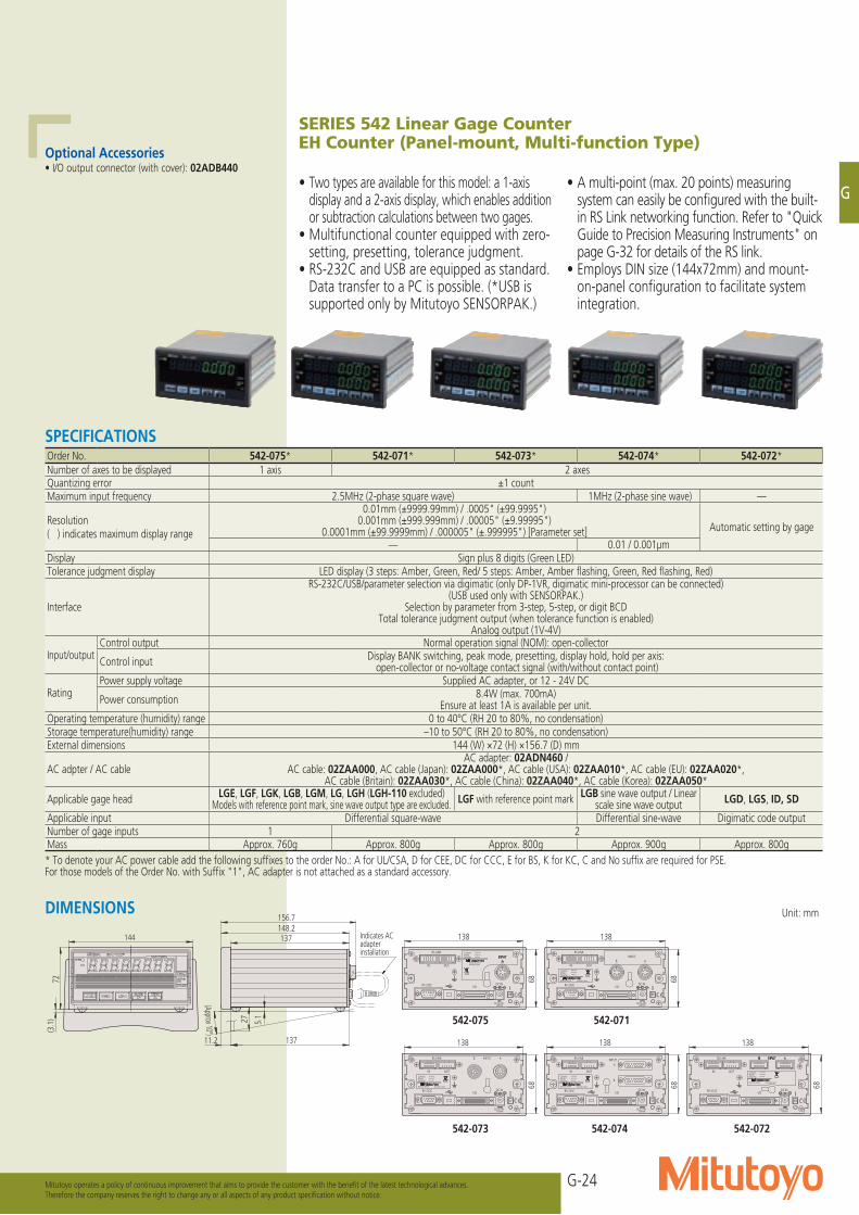
G-24
G
Mitutoyo operates a policy of continuous improvement that aims to provide the customer with the benefit of the latest technological advances.Therefore the company reserves the right to change any or all aspects of any product specification without notice.
IN
DC IN
INPUT
A
700mA
I/ORS-232C
OUT
RS LINK
DC12-24V
B
Code No. 542-***Model EH-12SSerial No. 000001
MADE IN JAPAN
4312
27
11.2
137
5.1
137
156.7
144
72(3
.1)
68
138
148.2Indicates AC adapter installation
(Approx 10°)
DC12-24V
RS LINK
IN OUT
RS-232C I/O
700mA
DC IN
Code No.ModelSerial No.
MADE IN JAPAN
********************
Kawasaki, Japan
INPUTAB
*******
Kawasaki, Japan
Code No.ModelSerial No.
MADE IN JAPAN
*************
DC12-24V
RS LINK
IN OUT
RS-232C I/O
700mA
DC IN
B AINPUT
*******
Kawasaki, Japan
Code No.ModelSerial No.
MADE IN JAPAN
*************
DC12-24V
RS LINK
IN OUT
RS-232C I/O
700mA
DC IN DC IN
700mA
I/ORS-232C
OUTIN
RS LINK
DC12-24V
*******
Kawasaki, Japan
Code No.ModelSerial No.
MADE IN JAPAN
************* B
AINPUT
Code No.ModelSerial No.
MADE IN JAPAN
********************
Kawasaki, Japan
DC12-24V
RS LINK
IN OUT
RS-232C I/O
700mA
DC IN
68
138
68
138
68
138
68
138
68
138
SERIES 542 Linear Gage CounterEH Counter (Panel-mount, Multi-function Type)
• Two types are available for this model: a 1-axis display and a 2-axis display, which enables addition or subtraction calculations between two gages.
• Multifunctional counter equipped with zero-setting, presetting, tolerance judgment.
• RS-232C and USB are equipped as standard. Data transfer to a PC is possible. (*USB is supported only by Mitutoyo SENSORPAK.)
• A multi-point (max. 20 points) measuring system can easily be configured with the built-in RS Link networking function. Refer to "Quick Guide to Precision Measuring Instruments" on page G-32 for details of the RS link.
• Employs DIN size (144x72mm) and mount-on-panel configuration to facilitate system integration.
Optional Accessories• I/O output connector (with cover): 02ADB440
Unit: mmDIMENSIONS
542-075 542-071
542-073 542-074 542-072
SPECIFICATIONSOrder No. 542-075* 542-071* 542-073* 542-074* 542-072*Number of axes to be displayed 1 axis 2 axesQuantizing error ±1 countMaximum input frequency 2.5MHz (2-phase square wave) 1MHz (2-phase sine wave) —
Resolution( ) indicates maximum display range
0.01mm (±9999.99mm) / .0005" (±99.9995")0.001mm (±999.999mm) / .00005" (±9.99995")
0.0001mm (±99.9999mm) / .000005" (±.999995") [Parameter set] Automatic setting by gage
— 0.01 / 0.001μmDisplay Sign plus 8 digits (Green LED)Tolerance judgment display LED display (3 steps: Amber, Green, Red/ 5 steps: Amber, Amber flashing, Green, Red flashing, Red)
Interface
RS-232C/USB/parameter selection via digimatic (only DP-1VR, digimatic mini-processor can be connected)(USB used only with SENSORPAK.)
Selection by parameter from 3-step, 5-step, or digit BCD Total tolerance judgment output (when tolerance function is enabled)
Analog output (1V-4V)
Input/outputControl output Normal operation signal (NOM): open-collector
Control input Display BANK switching, peak mode, presetting, display hold, hold per axis: open-collector or no-voltage contact signal (with/without contact point)
RatingPower supply voltage Supplied AC adapter, or 12 - 24V DC
Power consumption 8.4W (max. 700mA)Ensure at least 1A is available per unit.
Operating temperature (humidity) range 0 to 40°C (RH 20 to 80%, no condensation)Storage temperature(humidity) range –10 to 50°C (RH 20 to 80%, no condensation)External dimensions 144 (W) ×72 (H) ×156.7 (D) mm
AC adpter / AC cableAC adapter: 02ADN460 /
AC cable: 02ZAA000, AC cable (Japan): 02ZAA000*, AC cable (USA): 02ZAA010*, AC cable (EU): 02ZAA020*, AC cable (Britain): 02ZAA030*, AC cable (China): 02ZAA040*, AC cable (Korea): 02ZAA050*
Applicable gage head LGE, LGF, LGK, LGB, LGM, LG, LGH (LGH-110 excluded)Models with reference point mark, sine wave output type are excluded. LGF with reference point mark LGB sine wave output / Linear
scale sine wave output LGD, LGS, ID, SD
Applicable input Differential square-wave Differential sine-wave Digimatic code outputNumber of gage inputs 1 2Mass Approx. 760g Approx. 800g Approx. 800g Approx. 900g Approx. 800g* To denote your AC power cable add the following suffixes to the order No.: A for UL/CSA, D for CEE, DC for CCC, E for BS, K for KC, C and No suffix are required for PSE.For those models of the Order No. with Suffix "1", AC adapter is not attached as a standard accessory.
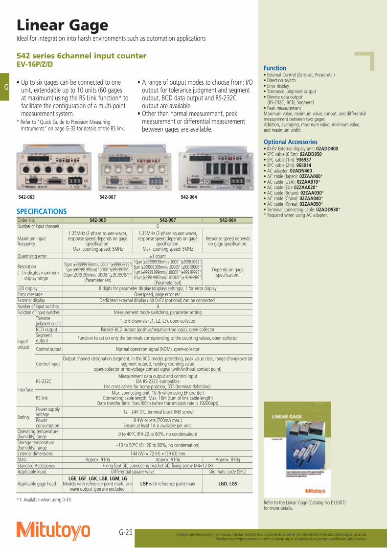
G-25
G
Linear GageIdeal for integration into harsh environments such as automation applications
Mitutoyo operates a policy of continuous improvement that aims to provide the customer with the benefit of the latest technological advances.Therefore the company reserves the right to change any or all aspects of any product specification without notice.
542 series 6channel input counterEV-16P/Z/D
• Up to six gages can be connected to one unit, extendable up to 10 units (60 gages at maximum) using the RS Link function* to facilitate the configuration of a multi-point measurement system.
* Refer to "Quick Guide to Precision Measuring Instruments" on page G-32 for details of the RS link.
• A range of output modes to choose from: I/O output for tolerance judgment and segment output, BCD data output and RS-232C output are available.
• Other than normal measurement, peak measurement or differential measurement between gages are available.
Function• External Control (Zero-set, Preset etc.)• Direction switch• Error display• Tolerance judgment output• Diverse data output (RS-232C, BCD, Segment)• Peak measurement Maximum value, minimum value, runout, and differential measurement between two gagesAddition, averaging, maximum value, minimum value, and maximum width
Optional Accessories• ID-EV External display unit: 02ADD400• SPC cable (0.5m): 02ADD950• SPC cable (1m): 936937• SPC cable (2m): 965014• AC adapter: 02ADN460• AC cable (Japan): 02ZAA000*• AC cable (USA): 02ZAA010*• AC cable (EU): 02ZAA020*• AC cable (Britain): 02ZAA030*• AC cable (China): 02ZAA040*• AC cable (Korea): 02ZAA050*• Terminal connecting cable: 02ADD930** Required when using AC adapter.
542-063 542-067 542-064
SPECIFICATIONSOrder No. 542-063 542-067 542-064Number of input channels 6
Maximum input frequency
1.25MHz (2-phase square wave), response speed depends on gage
specification. Max. counting speed: 5MHz
1.25MHz (2-phase square wave), response speed depends on gage
specification. Max. counting speed: 5MHz
Response speed depends on gage specification.
Quantizing error ±1 count
Resolution( ) indicates maximum
display range
10μm (±999999.99mm) / .0005" (±9999.9995")5μm (±999999.995mm) / .00005" (±999.99995")
0.5μm (±9999.9995mm) / .000005" (±.99.999995")*1
[Parameter set]
10μm (±999999.99mm) / .0005" (±9999.9995")5μm (±999999.995mm) / .00005" (±999.99995")1μm (±99999.999mm) / .00005" (±999.99995")0.5μm (±9999.9995mm) / .000005" (±.99.999995")
[Parameter set]
Depends on gage specification.
LED display 8 digits for parameter display (displays settings), 1 for error displayError message Overspeed, gage error etc.External display Dedicated external display unit D-EV (optional) can be connected.Number of input switches 4Function of input switches Measurement mode switching, parameter setting
Input/output
Tolerance judgment output 1 to 6 channels (L1, L2, L3), open-collector
BCD output Parallel BCD output (positive/negative-true logic), open-collectorSegment output Function to set on only the terminals corresponding to the counting values, open-collector
Control output Normal operation signal (NOM), open-collector
Control inputOutput channel designation (segment, in the BCD mode), presetting, peak value clear, range changeover (at
segment output), holding counting valueopen-collector or no-voltage contact signal (with/without contact point)
Interface
RS-232CMeasurement data output and control input
EIA RS-232C-compatibleUse cross cables for home position, DTE (terminal definition).
RS linkMax. connecting unit: 10 (6 when using EF counter)
Connecting cable length: Max. 10m (sum of link cable length)Data transfer time: 1sec./60ch (when transmission rate is 19200bps)
Rating
Power supply voltage 12 - 24V DC, terminal block (M3 screw)
Power consumption
8.4W or less (700mA max.)Ensure at least 1A is available per unit.
Operating temperature (humidity) range 0 to 40°C (RH 20 to 80%, no condensation)
Storage temperature (humidity) range –10 to 50°C (RH 20 to 80%, no condensation)
External dimensions 144 (W) × 72 (H) ×139 (D) mmMass Approx. 910g Approx. 910g Approx. 830gStandard Accessories Fixing foot (4), connecting bracket (4), fixing screw M4×12 (8)Applicable input Differential square-wave Digimatic code (SPC)
Applicable gage headLGE, LGF, LGK, LGB, LGM, LG
Models with reference point mark, sine wave output type are excluded.
LGF with reference point mark LGD, LGS
*1: Available when using D-EV. Refer to the Linear Gage (Catalog No.E13007) for more details.

G-26
G
Mitutoyo operates a policy of continuous improvement that aims to provide the customer with the benefit of the latest technological advances.Therefore the company reserves the right to change any or all aspects of any product specification without notice.
DIMENSIONS
144
6.5
4.54 4136
672
5 5161
16 16139
44
64
Code No.***-*** Model EV-16PCode No.***-***
RS LINKErr.OUTIN
LOAD 8 7 MODE 65 4
3 SEL. 2 1 DATA
F E D INPUT C B A
RS-232CIO/BCD
+V -V
DC12-24V700mA
6.5
4.5
644
4
139 1616136 44 161 55
726
144
1211
System ConfigurationA counter system performs output and display for connected Mitutoyo linear gages.
Linear Gages
PC(third party products)
Programmable controller(third party products)
D-EVDisplay Unit
EV Counter
EH CounterLinear Gages
RS-232C output
Tolerance judgment output/BCD outputSegment output/RS-232C output
136 44139 1616
726
161 55
6.5
4.5
144Fixing foot (4 pcs., standard accessories)
Connecting bracket (4 pcs., standard accessories) M4×8, pan head screw (8 pcs., standard accessories)
DATASEL.MODE 18 2367LOAD45
F E D C B A
RS LINKIN OUT
RS-232CIO/BCD
DC12-24V
+V -V
INPUT
Err.
700mASerial No. ******
Model EV-16DCode No.***-***
Refer to the Linear Gage (Catalog No.E13007) for more details.
Unit: mm
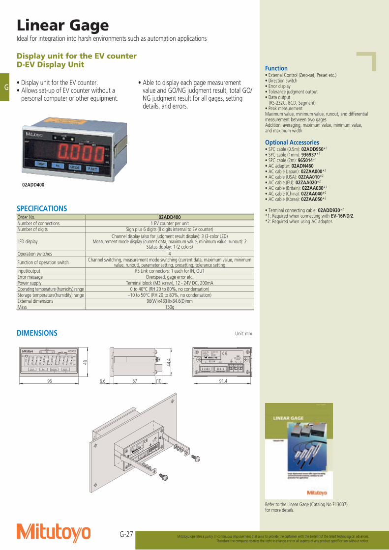
G-27
G
Linear GageIdeal for integration into harsh environments such as automation applications
Mitutoyo operates a policy of continuous improvement that aims to provide the customer with the benefit of the latest technological advances.Therefore the company reserves the right to change any or all aspects of any product specification without notice.
-V+V
-V+V
96 6.6 67 (11) 91.4
44.448
OUT000001EV-I02ADD400
MADE IN JAPANSerial No.ModelCode No.
200mADC12-24V
INRS LIN
K
MODE P.SETFnDISP
GAGE
MAX MINTIR
UNIT +NG
GO
-NG
000001EV-I02ADD400
MADE IN JAPAN
Serial No.ModelCode No.
200mADC12-24V
OUTIN RS LINK
Display unit for the EV counterD-EV Display Unit
• Display unit for the EV counter.• Allows set-up of EV counter without a
personal computer or other equipment.
• Able to display each gage measurement value and GO/NG judgment result, total GO/NG judgment result for all gages, setting details, and errors.
02ADD400
Function• External Control (Zero-set, Preset etc.)• Direction switch• Error display• Tolerance judgment output• Data output (RS-232C, BCD, Segment)• Peak measurement Maximum value, minimum value, runout, and differential measurement between two gagesAddition, averaging, maximum value, minimum value, and maximum width
Optional Accessories• SPC cable (0.5m): 02ADD950*1
• SPC cable (1mm): 936937*1
• SPC cable (2m): 965014*1
• AC adapter: 02ADN460• AC cable (Japan): 02ZAA000*2
• AC cable (USA): 02ZAA010*2
• AC cable (EU): 02ZAA020*2
• AC cable (Britain): 02ZAA030*2
• AC cable (China): 02ZAA040*2
• AC cable (Korea): 02ZAA050*2
• Terminal connecting cable: 02ADD930*2
*1: Required when connecting with EV-16P/D/Z.*2: Required when using AC adapter.
SPECIFICATIONSOrder No. 02ADD400Number of connections 1 EV counter per unit Number of digits Sign plus 6 digits (8 digits internal to EV counter)
LED displayChannel display (also for judgment result display): 3 (3-color LED)
Measurement mode display (current data, maximum value, minimum value, runout): 2Status display: 1 (2 colors)
Operation switches 4
Function of operation switch Channel switching, measurement mode switching (current data, maximum value, minimum value, runout), parameter setting, presetting, tolerance setting
Input/output RS Link connectors: 1 each for IN, OUTError message Overspeed, gage error etc.Power supply Terminal block (M3 screw), 12 - 24V DC, 200mAOperating temperature (humidity) range 0 to 40°C (RH 20 to 80%, no condensation)Storage temperature(humidity) range –10 to 50°C (RH 20 to 80%, no condensation)External dimensions 96(W)×48(H)×84.6(D)mmMass 150g
DIMENSIONS Unit: mm
Refer to the Linear Gage (Catalog No.E13007) for more details.
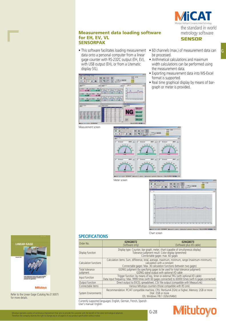
G-28
G
Mitutoyo operates a policy of continuous improvement that aims to provide the customer with the benefit of the latest technological advances.Therefore the company reserves the right to change any or all aspects of any product specification without notice.
Measurement data loading software for EH, EV, VLSENSORPAK
• This software facilitates loading measurement data onto a personal computer from a linear gage counter with RS-232C output (EH, EV), with USB output (EH), or from a Litematic display (VL).
• 60 channels (max.) of measurement data can be processed.
• Arithmetical calculations and maximum width calculations can be performed using the measurement data.
• Exporting measurement data into MS-Excel format is supported.
• Real time graphical display by means of bar-graph or meter is provided.
Measurement screen
Meter screen
Chart screen
Refer to the Linear Gage (Catalog No.E13007) for more details.
SPECIFICATIONSOrder No. 02NGB072
(Software only)02NGB073
(Software plus I/O cable)
Display functionDisplay type: Counter, bar graph, meter, chart (capable of simultaneous display)
Tolerance judgment result: Color display (green/red)Connectable gages: max. 60 gages
Calculation functionsCalculation items: Sum, difference, total, average, maximum, minimum, range (maximum–minimum),
calculation with a constantConnectable gages: Max. 30 calculation functions (between two gages)
Total tolerance judgment
GO/NG judgment (by specifying gages to be used for total tolerance judgment)GO/NG signal output with optional I/O cable
Input function Trigger function: by means of key, timer or external TRG (with optional I/O cable)Data input frequency: Max. 9999 times (with 60 gages connected) to 60000 times (with 6 gages connected)
Output function Direct output to EXCEL spreadsheet, CSV file output (compatible with MeasurLink)Connectable items Various Mitutoyo counters (those compatible with RS Link)
System EnvironmentsRecommendation: PC/AT compatible machine, CPU: Pentium4 2GHz or higher, Memory: 2GB or more
Disk: 2GB or moreOS: Windows 7/8.1 (32bit/64bit)
Currently supported languages: English, German, French, SpanishUser’s manual: English
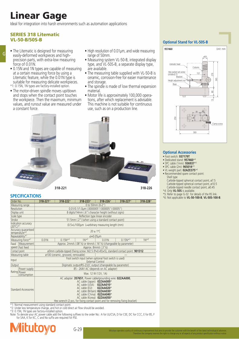
G-29
G
Linear GageIdeal for integration into harsh environments such as automation applications
Mitutoyo operates a policy of continuous improvement that aims to provide the customer with the benefit of the latest technological advances.Therefore the company reserves the right to change any or all aspects of any product specification without notice.
SERIES 318 LitematicVL-50-B/50S-B
• The Litematic is designed for measuring easily-deformed workpieces and high-precision parts, with extra-low measuring force of 0.01N.
• 0.15N and 1N types are capable of measuring at a certain measuring force by using a Litematic feature, while the 0.01N type is suitable for measuring delicate workpieces.
*1: 0.15N, 1N types are factory-installed option.• The motor-driven spindle moves up/down
and stops when the contact point touches the workpiece. Then the maximum, minimum values, and runout value are measured under a constant force.
• High resolution of 0.01μm, and wide measuring range of 50mm.
• Measuring system VL-50-B, integrated display type, and VL-50S-B, a separate display type, are available.
• The measuring table supplied with VL-50-B is ceramic, corrosion-free for easier maintenance and storage.
• The spindle is made of low thermal expansion material.
• Motor life is approximately 100,000 opera-tions, after which replacement is advisable.
This machine is not suitable for continuous use, such as on a production line.
Optional Stand for VL-50S-B
15
250
80
270
ø50
300
48 80
56
157
Clamp screw
365
Column
Height adjustment nut
Base
Bracket
Hex socket set screw(4-M4×0.7)
Litematic head
Unit: mm957460
Optional Accessories• Foot switch: 937179T• Dedicated stand: 957460*4
• SPC cable (1mm): 936937*5
• SPC cable (2m): 965014*5
• VL weight part: 02AZE375*6
• Recommended spare contact point: Shell type Carbide-tipped spherical contact point, ø7.5 Carbide-tipped spherical contact point, ø10.5 Carbide-tipped needle contact point, ø0.45*4: Only VL-50S is available. *5: Refer to page G-32 for details of the RS link.*6: Not applicable to VL-50-100-B, VL-50S-100-B.SPECIFICATIONS
Order No. 318-221* 318-222* 318-223* 318-226* 318-227* 318-228*Measuring range 0 to 50mm (0-2")Resolution 0.01/0.1/1.0μm (.0000005"/.000005"/.00005")Display unit 8 digits/14mm (.6") character height (without signs)Scale type Reflection type linear encoderStroke 51.5mm (.2") (when using a standard contact point)Indication accuracy (20°C)*1 (0.5+L/100)μm L=arbitrary measuring length (mm)
Accuracy guaranteed temperature*2 20 ± 1°C
Repeatability*1 =0.05μmMeasuring force*1 0.01N 0.15N*3 1N*3 0.01N 0.15N*3 1N*3
Feed speed
Measurement Approx. 2mm/s (.08"/s) or 4mm/s (.16"/s) (changeable by parameter)Fast feed Approx. 8mm/s (.3"/s)
Contact point ø3mm carbide-tipped (fixing screw: M2.5 (P=0.45)×5), standard contact point: 901312Measuring table ø100 (ceramic, grooved, removable) —
Input Foot switch input (when optional foot switch is used)External Control
Output Digimatic output/RS-232C output (changeable by parameter)
RatingPower supply 85 - 264V AC (depends on AC adapter)Power consumption Max. 12 W (12V, 1A)
Standard Accessories
AC adapter: 357651, Power cable/grounding wire: 02ZAA000, AC cable (Japan): 02ZAA000*AC cable (USA): 02ZAA010*AC cable (EU): 02ZAA020*AC cable (Britain): 02ZAA030*AC cable (China): 02ZAA040*AC cable (Korea): 02ZAA050*
Hex wrench (2 pcs, for fixing contact point and for removing fixing bracket)*1: Normal measurement using standard contact point.*2: Under less temperature change, and hot or cold direct air flow should be avoided.*3: 0.15N, 1N types are factory-installed option.Note: To denote your AC power cable add the following suffixes to the order No.: A for UL/CSA, D for CEE, DC for CCC, E for BS, F
for SAA, K for KC, C and No suffix are required for PSE.
318-226318-221
G-30
G
Mitutoyo operates a policy of continuous improvement that aims to provide the customer with the benefit of the latest technological advances.Therefore the company reserves the right to change any or all aspects of any product specification without notice.
85 150
170
82.9
5 ø32
12.5
29 80 14.8 1
72
186.4 50.2
80.2
(11°)
4-M4×0.7 depth 10
56
Scale unit
Display unit
Connecting cable 2m
VL-50-B
VL-50S-B
DIMENSIONS
Measurement Examples
Unit: mm
Glass dimensional measurement Thin sheet metal thickness
Thickness measurement of non-metallic sheet
202 300
103.2
56
380
.2
Measuring table ø100
Clamp screw for measuring table
Stylus
Display
Operation switch
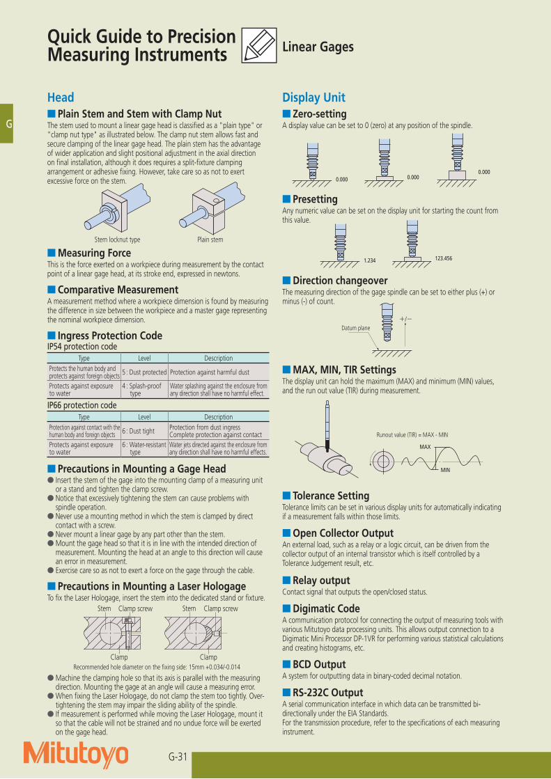
G-31
G
Laser Scan MicrometerTo realize non-contact, high-speed and high-precision measurement
Mitutoyo operates a policy of continuous improvement that aims to provide the customer with the benefit of the latest technological advances.Therefore the company reserves the right to change any or all aspects of any product specification without notice.
Head■ Plain Stem and Stem with Clamp NutThe stem used to mount a linear gage head is classified as a "plain type" or "clamp nut type" as illustrated below. The clamp nut stem allows fast and secure clamping of the linear gage head. The plain stem has the advantage of wider application and slight positional adjustment in the axial direction on final installation, although it does requires a split-fixture clamping arrangement or adhesive fixing. However, take care so as not to exert excessive force on the stem.
■ Measuring ForceThis is the force exerted on a workpiece during measurement by the contact point of a linear gage head, at its stroke end, expressed in newtons.
Stem locknut type Plain stem
■ Comparative MeasurementA measurement method where a workpiece dimension is found by measuring the difference in size between the workpiece and a master gage representing the nominal workpiece dimension.
ナット付ステム ストレートステム
■ Precautions in Mounting a Gage Head●Insert the stem of the gage into the mounting clamp of a measuring unit
or a stand and tighten the clamp screw.●Notice that excessively tightening the stem can cause problems with
spindle operation.●Never use a mounting method in which the stem is clamped by direct
contact with a screw.●Never mount a linear gage by any part other than the stem.●Mount the gage head so that it is in line with the intended direction of
measurement. Mounting the head at an angle to this direction will cause an error in measurement.
●Exercise care so as not to exert a force on the gage through the cable.
●Machine the clamping hole so that its axis is parallel with the measuring direction. Mounting the gage at an angle will cause a measuring error.
●When fixing the Laser Hologage, do not clamp the stem too tightly. Over-tightening the stem may impair the sliding ability of the spindle.
●If measurement is performed while moving the Laser Hologage, mount it so that the cable will not be strained and no undue force will be exerted on the gage head.
Stem StemClamp screw Clamp screw
Clamp Clamp
■ Precautions in Mounting a Laser HologageTo fix the Laser Hologage, insert the stem into the dedicated stand or fixture.
Display Unit
■ PresettingAny numeric value can be set on the display unit for starting the count from this value.
■ Direction changeoverThe measuring direction of the gage spindle can be set to either plus (+) or minus (-) of count.
■ MAX, MIN, TIR SettingsThe display unit can hold the maximum (MAX) and minimum (MIN) values, and the run out value (TIR) during measurement.
■ Tolerance SettingTolerance limits can be set in various display units for automatically indicating if a measurement falls within those limits.
■ Open Collector OutputAn external load, such as a relay or a logic circuit, can be driven from the collector output of an internal transistor which is itself controlled by a Tolerance Judgement result, etc.
■ Relay outputContact signal that outputs the open/closed status.
■ Digimatic CodeA communication protocol for connecting the output of measuring tools with various Mitutoyo data processing units. This allows output connection to a Digimatic Mini Processor DP-1VR for performing various statistical calculations and creating histograms, etc.
■ BCD OutputA system for outputting data in binary-coded decimal notation.
■ RS-232C OutputA serial communication interface in which data can be transmitted bi-directionally under the EIA Standards.For the transmission procedure, refer to the specifications of each measuring instrument.
振れ値=最大値-最小値
MAX
MIN
0.000 0.0000.000
+/-基準面
1.234 123.456
G■ Zero-settingA display value can be set to 0 (zero) at any position of the spindle.
IP54 protection codeType Level Description
Protects the human body and protects against foreign objects 5 : Dust protected Protection against harmful dust
Protects against exposure to water
4 : Splash-proof type
Water splashing against the enclosure from any direction shall have no harmful effect.
IP66 protection codeType Level Description
Protection against contact with the human body and foreign objects 6 : Dust tight Protection from dust ingress
Complete protection against contactProtects against exposure to water
6 : Water-resistant type
Water jets directed against the enclosure from any direction shall have no harmful effects.
■ Ingress Protection Code
Linear GagesQuick Guide to Precision Measuring Instruments
Datum plane
Runout value (TIR) = MAX - MIN
Recommended hole diameter on the fixing side: 15mm +0.034/-0.014
G-31
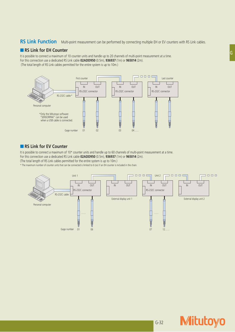
G-32
G
Mitutoyo operates a policy of continuous improvement that aims to provide the customer with the benefit of the latest technological advances.Therefore the company reserves the right to change any or all aspects of any product specification without notice.
RS Link Function Multi-point measurement can be performed by connecting multiple EH or EV counters with RS Link cables.
■ RS Link for EH CounterIt is possible to connect a maximum of 10 counter units and handle up to 20 channels of multi-point measurement at a time.For this connection use a dedicated RS Link cable 02ADD950 (0.5m), 936937 (1m) or 965014 (2m). (The total length of RS Link cables permitted for the entire system is up to 10m.)
Personal computer
IN
RS-232C connector
First counter
RS-232C cable *
01 Gage number 02 03 04……
Last counter
OUT IN
RS-232C connector
OUT IN
RS-232C connector
OUT
Personal computer
IN
RS-232C connector
Unit 2
RS-232C cable
01Gage number 06 07 12……
…… ……
OUT IN OUT IN OUT
External display unit 1 External display unit 2
IN OUT
Unit 1
RS-232C connector
■ RS Link for EV CounterIt is possible to connect a maximum of 10* counter units and handle up to 60 channels of multi-point measurement at a time.For this connection use a dedicated RS Link cable 02ADD950 (0.5m), 936937 (1m) or 965014 (2m). (The total length of RS Link cables permitted for the entire system is up to 10m.)* The maximum number of counter units that can be connected is limited to 6 (six) if an EH counter is included in the chain.
G
*Only the Mitutoyo software “SENSORPAK” can be used
when a USB cable is connected.
G-32