Embed Size (px)
Citation preview
R. G. Sparber September 7, 2011 Page 1 of 12
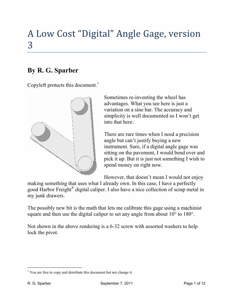
A Low Cost “Digital” Angle Gage, version
3
By R. G. Sparber Copyleft protects this document.
1
Sometimes re-inventing the wheel has
advantages. What you see here is just a
variation on a sine bar. The accuracy and
simplicity is well documented so I won’t get
into that here.
There are rare times when I need a precision
angle but can’t justify buying a new
instrument. Sure, if a digital angle gage was
sitting on the pavement, I would bend over and
pick it up. But it is just not something I wish to
spend money on right now.
However, that doesn’t mean I would not enjoy
making something that uses what I already own. In this case, I have a perfectly
good Harbor Freight® digital caliper. I also have a nice collection of scrap metal in
my junk drawers.
The possibly new bit is the math that lets me calibrate this gage using a machinist
square and then use the digital caliper to set any angle from about 10° to 180°.
Not shown in the above rendering is a 6-32 screw with assorted washers to help
lock the pivot.
1 You are free to copy and distribute this document but not change it.
R. G. Sparber September 7, 2011 Page 2 of 12
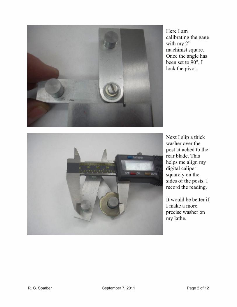
Here I am
calibrating the gage
with my 2”
machinist square.
Once the angle has
been set to 90°, I
lock the pivot.
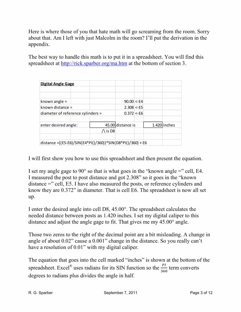
Next I slip a thick
washer over the
post attached to the
rear blade. This
helps me align my
digital caliper
squarely on the
sides of the posts. I
record the reading.
It would be better if
I make a more
precise washer on
my lathe.
R. G. Sparber September 7, 2011 Page 3 of 12
Digital Angle Gage
known angle = 90.00 <-E4
known distance = 2.308 <-E5
diameter of reference cylinders = 0.372 <-E6
enter desired angle: 45.00 distance is 1.420 inches
/\ is D8
distance =((E5-E6)/SIN(E4*PI()/360))*SIN(D8*PI()/360) + E6
Here is where those of you that hate math will go screaming from the room. Sorry
about that. Am I left with just Malcolm in the room? I’ll put the derivation in the
appendix.
The best way to handle this math is to put it in a spreadsheet. You will find this
spreadsheet at http://rick.sparber.org/ma.htm at the bottom of section 3.
I will first show you how to use this spreadsheet and then present the equation.
I set my angle gage to 90° so that is what goes in the “known angle =” cell, E4.
I measured the post to post distance and got 2.308” so it goes in the “known
distance =” cell, E5. I have also measured the posts, or reference cylinders and
know they are 0.372” in diameter. That is cell E6. The spreadsheet is now all set
up.
I enter the desired angle into cell D8, 45.00°. The spreadsheet calculates the
needed distance between posts as 1.420 inches. I set my digital caliper to this
distance and adjust the angle gage to fit. That gives me my 45.00° angle.
Those two zeros to the right of the decimal point are a bit misleading. A change in
angle of about 0.02” cause a 0.001” change in the distance. So you really can’t
have a resolution of 0.01” with my digital caliper.
The equation that goes into the cell marked “inches” is shown at the bottom of the
spreadsheet. Excel® uses radians for its SIN function so the
��
��� term converts
degrees to radians plus divides the angle in half.
R. G. Sparber September 7, 2011 Page 4 of 12
I made my gage
from aluminum
since it was a proof
of concept. Ideally
it would be made
from steel,
hardened, and
ground. Given how
often I will
probably use this
gage, I’ll probably
stay with aluminum.
Few of the
dimensions are
critical. Have a
snug fit between the holes and round stock. The hole spacing must be identical so
it is best to stack the blades and drill through both parts at the same time. The outer
edges do have to be true and flat. The posts must be perpendicular to the surface of
the blades so it is best to side mill the blades and drill the holes without disturbing
the parts.
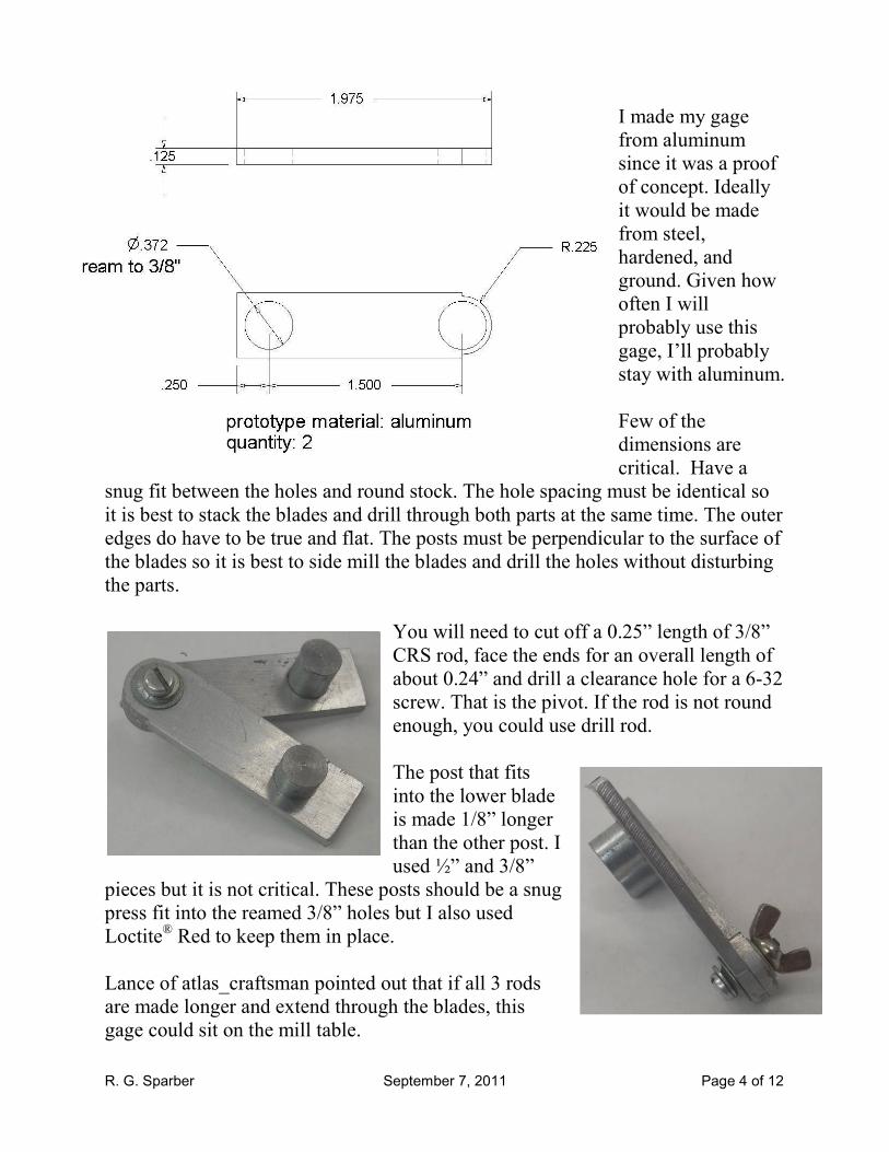
You will need to cut off a 0.25” length of 3/8”
CRS rod, face the ends for an overall length of
about 0.24” and drill a clearance hole for a 6-32
screw. That is the pivot. If the rod is not round
enough, you could use drill rod.
The post that fits
into the lower blade
is made 1/8” longer
than the other post. I
used ½” and 3/8”
pieces but it is not critical. These posts should be a snug
press fit into the reamed 3/8” holes but I also used
Loctite® Red to keep them in place.
Lance of atlas_craftsman pointed out that if all 3 rods
are made longer and extend through the blades, this
gage could sit on the mill table.

R. G. Sparber September 7, 2011 Page 5 of 12
Appendix In the following discussion, I will number each
assumption that affects accuracy and then discuss
them at the end.
Take a triangle with two sides with the same length
(1). These sides form an angle, A, where they join (2).
The third side is the base and is marked B.
If I drop a line straight down from the top of this triangle
to the base, I get a right triangle with hypotenuse, S, and an
angle �
�. The base has a length of
�
�.
I can say
��
� �
�� �
�
Solving for S I get
� ��
� �� �
In other words, we don’t need to measure S as long as we
know the angle, ���and the distance B.
R. G. Sparber September 7, 2011 Page 6 of 12
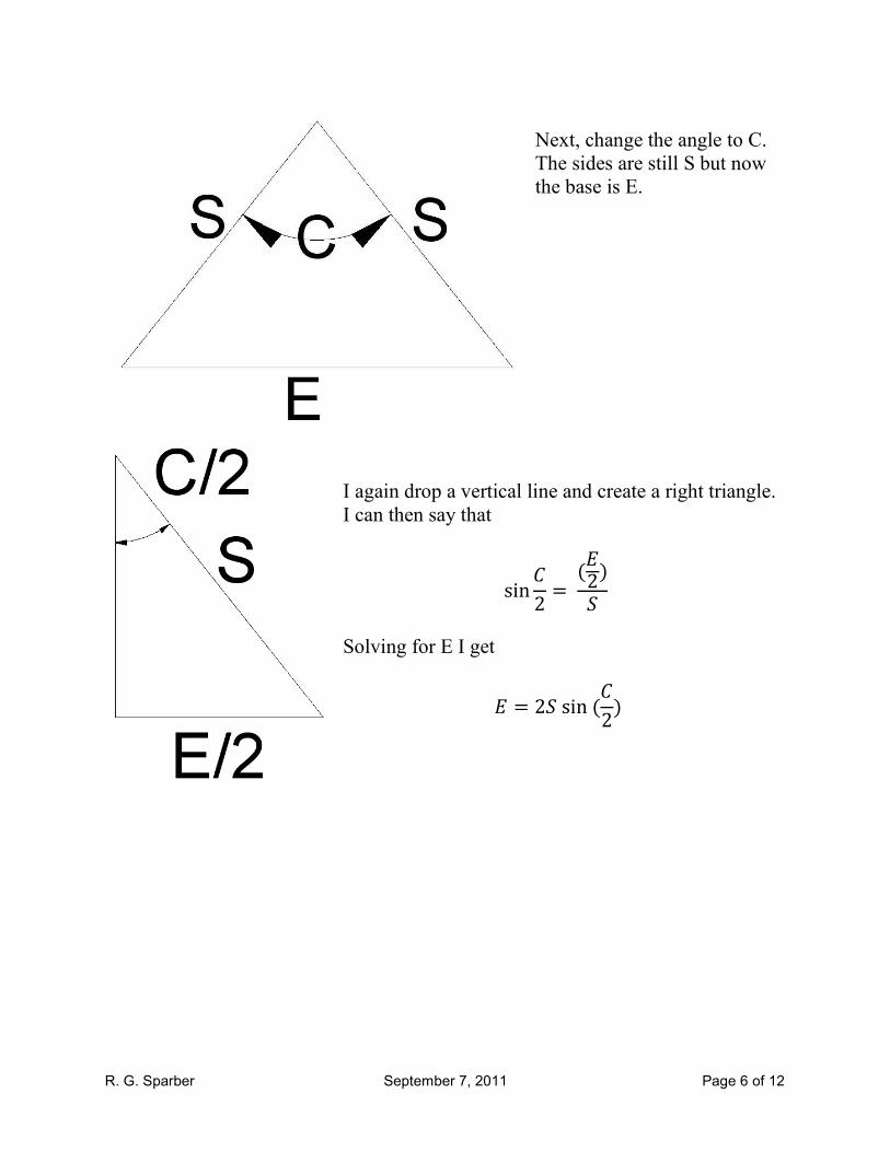
Next, change the angle to C.
The sides are still S but now
the base is E.
I again drop a vertical line and create a right triangle.
I can then say that
��
� �
�� �
��
Solving for E I get
� � ������
�

R. G. Sparber September 7, 2011 Page 7 of 12
I know that �
� ��
� �� ��
and
� � ������
�
So can combine these equations and eliminate the S variable
�
� � ��
� �� ������
�
�
� ��
��� �����
�
�
This equation says that if I set angle A and measure distance B, I can
then use this equation to set any angle, C, by setting distance E.
There is still one more step before this equation is usable. I must take
into account the posts.

R. G. Sparber September 7, 2011 Page 8 of 12
I have measured the diameter of one post. Since they were
all cut from the same rod, they should both be the same
diameter. If they are not, you can turn them to the same
diameter or change to drill rod. You could also just live
with the error by carrying the radius of each post in the
equation. Now, if the posts are not round, then replace
them.
Note that
� � � � �������� !" � � #$����� !"
Assuming the posts are the same diameters, then
� � � � � �%���� So
� � � & � �%����
Similarly, I can say
� � ' & � �%���� °
Putting this all together, I get
� ��
��� �����
�
�
' & � �%���� �� & � �%����
��� �
�����
�
Or
' � � �%���� �� & � �%����
��� �
�����
�
R. G. Sparber September 7, 2011 Page 9 of 12
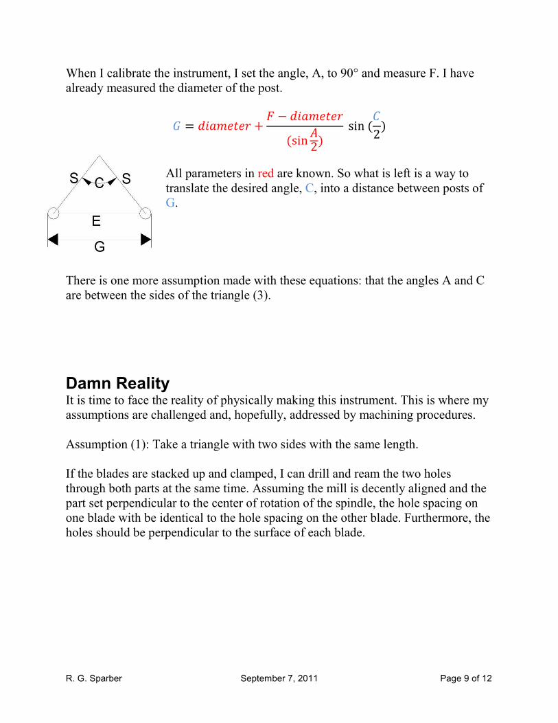
When I calibrate the instrument, I set the angle, A, to 90° and measure F. I have
already measured the diameter of the post.
' � � �%���� �� & � �%����
��� �
�����
�
All parameters in red are known. So what is left is a way to
translate the desired angle, C, into a distance between posts of
G.
There is one more assumption made with these equations: that the angles A and C
are between the sides of the triangle (3).
Damn Reality It is time to face the reality of physically making this instrument. This is where my
assumptions are challenged and, hopefully, addressed by machining procedures.
Assumption (1): Take a triangle with two sides with the same length.
If the blades are stacked up and clamped, I can drill and ream the two holes
through both parts at the same time. Assuming the mill is decently aligned and the
part set perpendicular to the center of rotation of the spindle, the hole spacing on
one blade with be identical to the hole spacing on the other blade. Furthermore, the
holes should be perpendicular to the surface of each blade.
R. G. Sparber September 7, 2011 Page 10 of 12
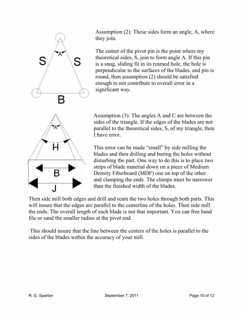
Assumption (2): These sides form an angle, A, where
they join.
The center of the pivot pin is the point where my
theoretical sides, S, join to form angle A. If this pin
is a snug, sliding fit in its reamed hole, the hole is
perpendicular to the surfaces of the blades, and pin is
round, then assumption (2) should be satisfied
enough to not contribute to overall error in a
significant way.
Assumption (3): The angles A and C are between the
sides of the triangle. If the edges of the blades are not
parallel to the theoretical sides, S, of my triangle, then
I have error.
This error can be made “small” by side milling the
blades and then drilling and boring the holes without
disturbing the part. One way to do this is to place two
strips of blade material down on a piece of Medium
Density Fiberboard (MDF) one on top of the other
and clamping the ends. The clamps must be narrower
than the finished width of the blades.
Then side mill both edges and drill and ream the two holes through both parts. This
will insure that the edges are parallel to the centerline of the holes. Then side mill
the ends. The overall length of each blade is not that important. You can free hand
file or sand the smaller radius at the pivot end.
This should insure that the line between the centers of the holes is parallel to the
sides of the blades within the accuracy of your mill.
R. G. Sparber September 7, 2011 Page 11 of 12
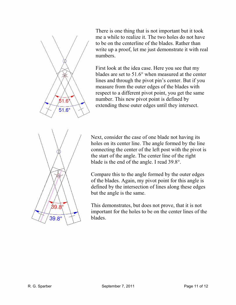
There is one thing that is not important but it took
me a while to realize it. The two holes do not have
to be on the centerline of the blades. Rather than
write up a proof, let me just demonstrate it with real
numbers.
First look at the idea case. Here you see that my
blades are set to 51.6° when measured at the center
lines and through the pivot pin’s center. But if you
measure from the outer edges of the blades with
respect to a different pivot point, you get the same
number. This new pivot point is defined by
extending these outer edges until they intersect.
Next, consider the case of one blade not having its
holes on its center line. The angle formed by the line
connecting the center of the left post with the pivot is
the start of the angle. The center line of the right
blade is the end of the angle. I read 39.8°.
Compare this to the angle formed by the outer edges
of the blades. Again, my pivot point for this angle is
defined by the intersection of lines along these edges
but the angle is the same.
This demonstrates, but does not prove, that it is not
important for the holes to be on the center lines of the
blades.

R. G. Sparber September 7, 2011 Page 12 of 12
Overall Check of Instrument
In the end, the only way to check this instrument is to calibrate it with one known
angle and then test it against another known angle. This should give you an overall
check of your work.
Acknowledgement Thanks to Malcolm of gingery_machines for pointing out that the blades should be
match drilled and also for checking my math. Thanks to Lance of atlas_craftsman
for his suggested new application on a mill table. Thanks to Richard of
atlas_craftsman for encouraging me to add the appendix.
I welcome your comments and questions.
Rick Sparber