Embed Size (px)
Citation preview
L-GAGE® LH Series Sensor
Instruction Manual
Original Instructions152154 Rev. D9 May 2017© Banner Engineering Corp. All rights reserved
152154
Contents1 Introduction ..................................................................................................................................................................... 32 LH Series Installation and Setup ........................................................................................................................................4
2.1 Cable/Connector Wiring .........................................................................................................................................................................42.2 Installation ..............................................................................................................................................................................................4
2.2.1 Displacement Measurement Installation ................................................................................................................................. 42.2.2 Thickness Delta Measurement Installation .............................................................................................................................. 5
2.3 Handling and Storage ............................................................................................................................................................................ 63 LH Series Configurator Software ....................................................................................................................................... 7
3.1 Software Installation ............................................................................................................................................................................. 73.2 Starting Up the LH Series Configurator ................................................................................................................................................. 83.3 LH Series Configurator Main Screen .......................................................................................................................................................9
4 Specifications ................................................................................................................................................................ 114.1 General Specifications .......................................................................................................................................................................... 114.2 Performance Specifications ..................................................................................................................................................................114.3 Indicators ............................................................................................................................................................................................. 12
4.3.1 Green Power LED .....................................................................................................................................................................124.3.2 Amber Signal LED .................................................................................................................................................................... 124.3.3 LED Indicators and Outputs ..................................................................................................................................................... 13
4.4 Dimensions ........................................................................................................................................................................................... 145 Accessories .....................................................................................................................................................................15
5.1 Brackets ............................................................................................................................................................................................... 155.2 INTUSB485-LH Adapter ........................................................................................................................................................................ 155.3 Cordsets ...............................................................................................................................................................................................15
6 Banner Engineering Corp. Limited Warranty .................................................................................................................. 186.1 Contact Us ........................................................................................................................................................................................... 18
L-GAGE® LH Series Sensor
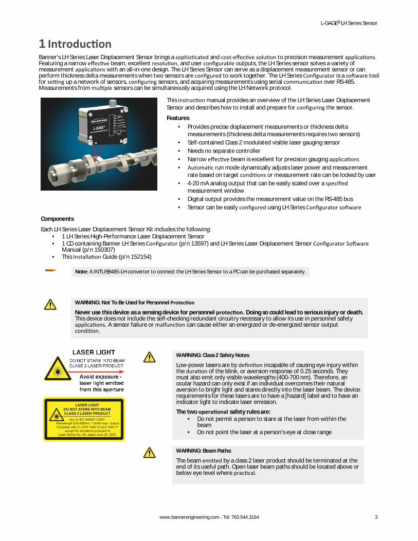
1 IntroductionBanner's LH Series Laser Displacement Sensor brings a sophisticated and cost-effective solution to precision measurement applications.Featuring a narrow effective beam, excellent resolution, and user configurable outputs, the LH Series sensor solves a variety ofmeasurement applications with an all-in-one design. The LH Series Sensor can serve as a displacement measurement sensor or canperform thickness delta measurements when two sensors are configured to work together. The LH Series Configurator is a software toolfor setting up a network of sensors, configuring sensors, and acquiring measurements using serial communication over RS-485.Measurements from multiple sensors can be simultaneously acquired using the LH Network protocol.
This instruction manual provides an overview of the LH Series Laser DisplacementSensor and describes how to install and prepare for configuring the sensor.
Features• Provides precise displacement measurements or thickness delta
measurements (thickness delta measurements requires two sensors)• Self-contained Class 2 modulated visible laser gauging sensor• Needs no separate controller• Narrow effective beam is excellent for precision gauging applications• Automatic run mode dynamically adjusts laser power and measurement
rate based on target conditions or measurement rate can be locked by user• 4-20 mA analog output that can be easily scaled over a specified
measurement window• Digital output provides the measurement value on the RS-485 bus• Sensor can be easily configured using LH Series Configurator software
Components
Each LH Series Laser Displacement Sensor Kit includes the following:• 1 LH Series High-Performance Laser Displacement Sensor• 1 CD containing Banner LH Series Configurator (p/n 13597) and LH Series Laser Displacement Sensor Configurator Software
Manual (p/n 150307)• This Installation Guide (p/n 152154)
Note: A INTUSB485-LH converter to connect the LH Series Sensor to a PC can be purchased separately.
WARNING: Not To Be Used for Personnel Protection
Never use this device as a sensing device for personnel protection. Doing so could lead to serious injury or death.This device does not include the self-checking redundant circuitry necessary to allow its use in personnel safetyapplications. A sensor failure or malfunction can cause either an energized or de-energized sensor outputcondition.
WARNING: Class 2 Safety Notes
Low-power lasers are by definition incapable of causing eye injury withinthe duration of the blink, or aversion response of 0.25 seconds. Theymust also emit only visible wavelengths (400-700 nm). Therefore, anocular hazard can only exist if an individual overcomes their naturalaversion to bright light and stares directly into the laser beam. The devicerequirements for these lasers are to have a [hazard] label and to have anindicator light to indicate laser emission.The two operational safety rules are:
• Do not permit a person to stare at the laser from within thebeam
• Do not point the laser at a person's eye at close range
WARNING: Beam Paths:
The beam emitted by a class 2 laser product should be terminated at theend of its useful path. Open laser beam paths should be located above orbelow eye level where practical.
L-GAGE® LH Series Sensor
www.bannerengineering.com - Tel: 763.544.3164 3
2 LH Series Installation and Setup2.1 Cable/Connector Wiring
Pin Color Description
18-30V dc–
+2
7
–
+14-20 mA
3
5
6
4
8Shield/Drain
Wire*
RS-485 GND
RS-485 RX+/TX+
RS-485 RX-/TX-
1 White 4-20 mA output source
2 Brown Power supply 18–30 V dc
3 Shield (bundled with whitewire inside blue foil wrap)
4-20 mA output return
4 Yellow RS-485 RX- / TX-
5 Grey Ground of RS-485 bus
6 Green RS-485 RX+ / TX+
7 Blue Ground
8 Shield Shield/drain wire*
* The shield/drain wire is connected internally to the sensor housing and should be connected as follows:1. If the sensor housing is mounted so that it is in continuity with both the machine frame and earth ground, connect the shield/
drain wire (also) to earth ground.2. If the sensor housing is mounted so that it is insulated from the machine frame, connect the shield/drain wire to -V dc (together
with the blue wire).3. If the sensor is mounted so that it is in continuity with the machine frame, but not with earth ground, do not connect the
shield/drain wire (i.e. cut off the shield/drain wire).
2.2 InstallationThe LH Series Laser Displacement Sensor is an optical instrument capable of micrometer-level resolutions.
Note: Handle the sensor with care when installing and operating. Applications requiring measurement resolution in themicrometer range must take vibration, dust, and thermal expansion effects into consideration. Windows of all sensors must beclean for full functionality. Windows that are soiled by dust, water, oil, etc may cause the sensor to not operate correctly. Thewindows should be cleaned thoroughly whenever necessary, using a high quality glass cleaner.
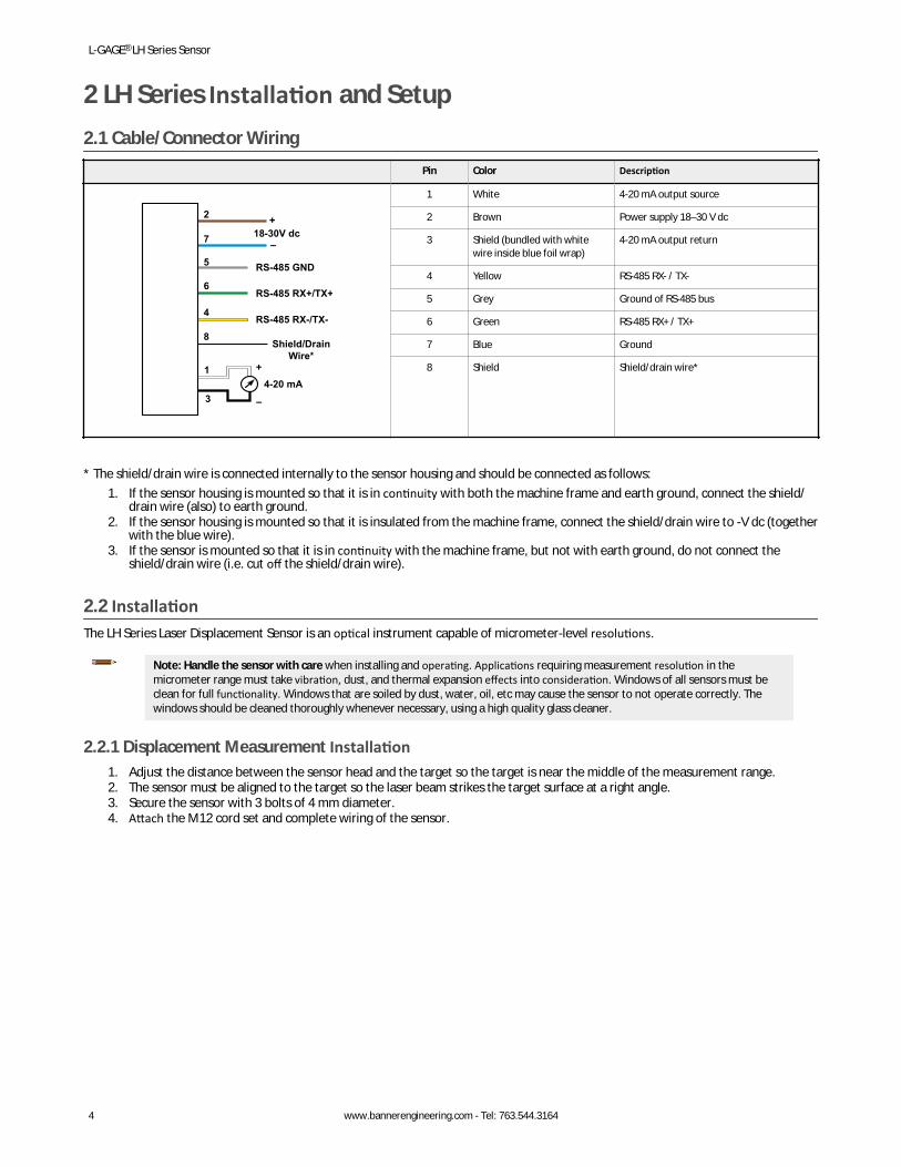
2.2.1 Displacement Measurement Installation1. Adjust the distance between the sensor head and the target so the target is near the middle of the measurement range.2. The sensor must be aligned to the target so the laser beam strikes the target surface at a right angle.3. Secure the sensor with 3 bolts of 4 mm diameter.4. Attach the M12 cord set and complete wiring of the sensor.
L-GAGE® LH Series Sensor
4 www.bannerengineering.com - Tel: 763.544.3164
TARGET
Measurement Range Reference
Start of Measurement Range
Reference Distance
End of Measurement Range
LH SeriesSensor
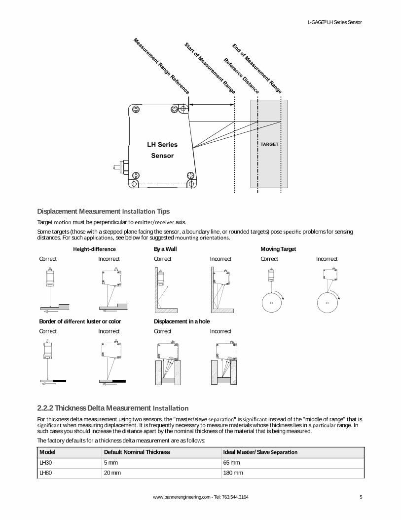
Displacement Measurement Installation TipsTarget motion must be perpendicular to emitter/receiver axis.Some targets (those with a stepped plane facing the sensor, a boundary line, or rounded targets) pose specific problems for sensingdistances. For such applications, see below for suggested mounting orientations.
Height-difference By a Wall Moving TargetCorrect Incorrect Correct Incorrect Correct Incorrect
AB
AB
A BA B
A BA B
Border of different luster or color Displacement in a holeCorrect Incorrect Correct Incorrect
A BA B A BA B
2.2.2 Thickness Delta Measurement InstallationFor thickness delta measurement using two sensors, the "master/slave separation" is significant instead of the "middle of range" that issignificant when measuring displacement. It is frequently necessary to measure materials whose thickness lies in a particular range. Insuch cases you should increase the distance apart by the nominal thickness of the material that is being measured.The factory defaults for a thickness delta measurement are as follows:
Model Default Nominal Thickness Ideal Master/Slave Separation
LH30 5 mm 65 mm
LH80 20 mm 180 mm
L-GAGE® LH Series Sensor
www.bannerengineering.com - Tel: 763.544.3164 5
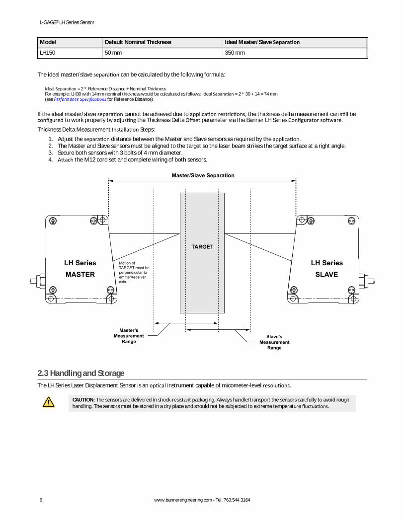
Model Default Nominal Thickness Ideal Master/Slave Separation
LH150 50 mm 350 mm
The ideal master/slave separation can be calculated by the following formula:
Ideal Separation = 2 * Reference Distance + Nominal ThicknessFor example: LH30 with 14mm nominal thickness would be calculated as follows: Ideal Separation = 2 * 30 + 14 = 74 mm(see Performance Specifications for Reference Distance)
If the ideal master/slave separation cannot be achieved due to application restrictions, the thickness delta measurement can still beconfigured to work properly by adjusting the Thickness Delta Offset parameter via the Banner LH Series Configurator software.Thickness Delta Measurement Installation Steps:
1. Adjust the separation distance between the Master and Slave sensors as required by the application.2. The Master and Slave sensors must be aligned to the target so the laser beam strikes the target surface at a right angle.3. Secure both sensors with 3 bolts of 4 mm diameter.4. Attach the M12 cord set and complete wiring of both sensors.
LH SeriesSLAVE
LH SeriesMASTER
TARGET
Master’sMeasurement
RangeSlave’s
MeasurementRange
Master/Slave Separation
Motion of TARGET must be perpendicular to emitter/receiver axis.
2.3 Handling and StorageThe LH Series Laser Displacement Sensor is an optical instrument capable of micometer-level resolutions.
CAUTION: The sensors are delivered in shock-resistant packaging. Always handle/transport the sensors carefully to avoid roughhandling. The sensors must be stored in a dry place and should not be subjected to extreme temperature fluctuations.
L-GAGE® LH Series Sensor
6 www.bannerengineering.com - Tel: 763.544.3164
3 LH Series Configurator SoftwareThe LH Series Configurator CD (P/N 13597) includes the LH Series Configurator software and the LH Series Laser Displacement SensorConfigurator Software Manual (P/N 150307).
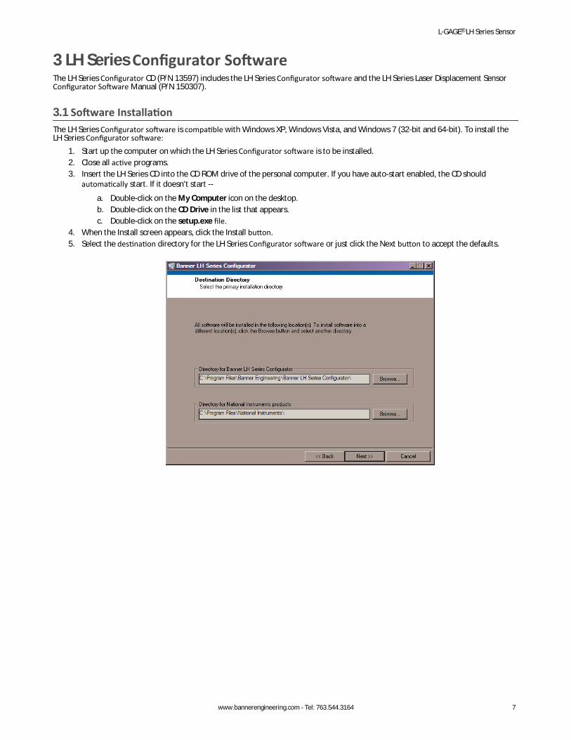
3.1 Software InstallationThe LH Series Configurator software is compatible with Windows XP, Windows Vista, and Windows 7 (32-bit and 64-bit). To install theLH Series Configurator software:
1. Start up the computer on which the LH Series Configurator software is to be installed.2. Close all active programs.3. Insert the LH Series CD into the CD ROM drive of the personal computer. If you have auto-start enabled, the CD should
automatically start. If it doesn't start --
a. Double-click on the My Computer icon on the desktop.b. Double-click on the CD Drive in the list that appears.c. Double-click on the setup.exe file.
4. When the Install screen appears, click the Install button.5. Select the destination directory for the LH Series Configurator software or just click the Next button to accept the defaults.
L-GAGE® LH Series Sensor
www.bannerengineering.com - Tel: 763.544.3164 7
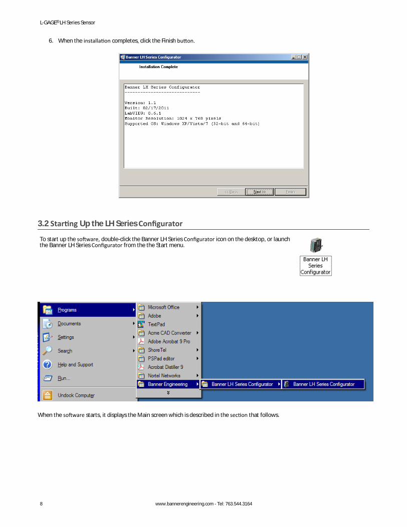
6. When the installation completes, click the Finish button.
3.2 Starting Up the LH Series Configurator
To start up the software, double-click the Banner LH Series Configurator icon on the desktop, or launchthe Banner LH Series Configurator from the the Start menu.
When the software starts, it displays the Main screen which is described in the section that follows.
L-GAGE® LH Series Sensor
8 www.bannerengineering.com - Tel: 763.544.3164
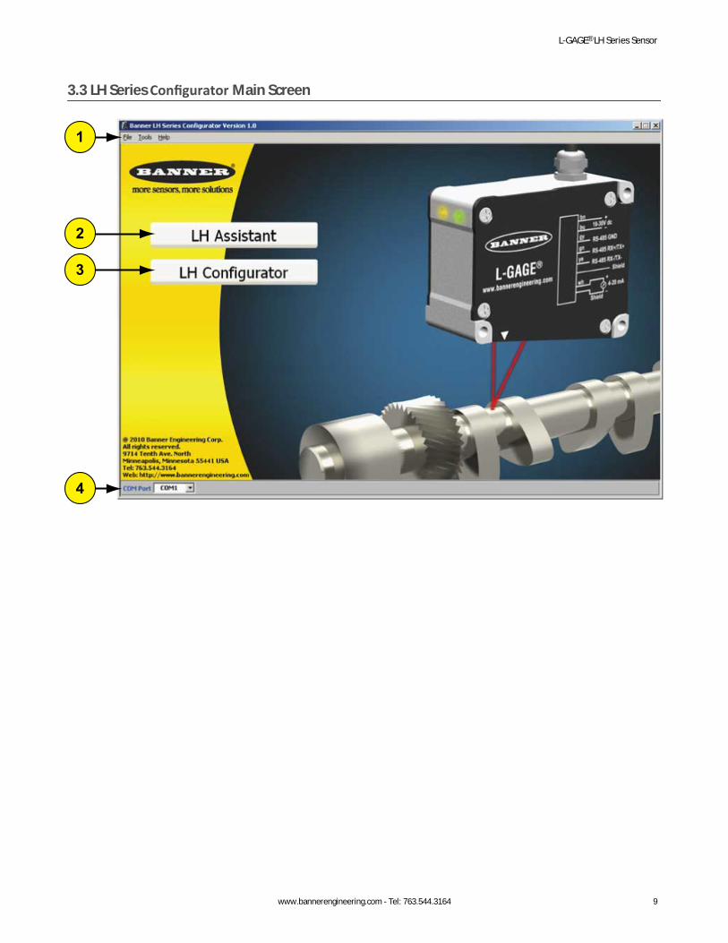
3.3 LH Series Configurator Main Screen
1
2
3
4
L-GAGE® LH Series Sensor
www.bannerengineering.com - Tel: 763.544.3164 9
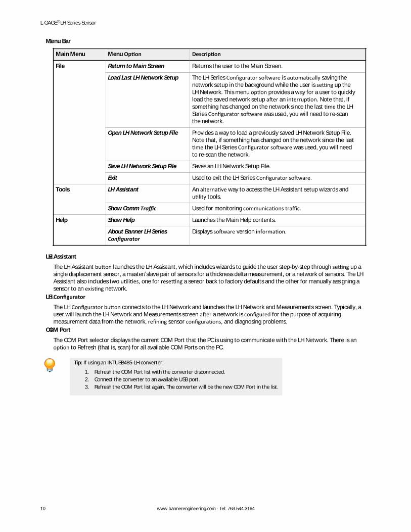
1.Menu Bar
Main Menu Menu Option Description
File Return to Main Screen Returns the user to the Main Screen.
Load Last LH Network Setup The LH Series Configurator software is automatically saving thenetwork setup in the background while the user is setting up theLH Network. This menu option provides a way for a user to quicklyload the saved network setup after an interruption. Note that, ifsomething has changed on the network since the last time the LHSeries Configurator software was used, you will need to re-scanthe network.
Open LH Network Setup File Provides a way to load a previously saved LH Network Setup File.Note that, if something has changed on the network since the lasttime the LH Series Configurator software was used, you will needto re-scan the network.
Save LH Network Setup File Saves an LH Network Setup File.
Exit Used to exit the LH Series Configurator software.
Tools LH Assistant An alternative way to access the LH Assistant setup wizards andutility tools.
Show Comm Traffic Used for monitoring communications traffic.
Help Show Help Launches the Main Help contents.
About Banner LH SeriesConfigurator
Displays software version information.
2.LH Assistant
The LH Assistant button launches the LH Assistant, which includes wizards to guide the user step-by-step through setting up asingle displacement sensor, a master/slave pair of sensors for a thickness delta measurement, or a network of sensors. The LHAssistant also includes two utilities, one for resetting a sensor back to factory defaults and the other for manually assigning asensor to an existing network.
3.LH Configurator
The LH Configurator button connects to the LH Network and launches the LH Network and Measurements screen. Typically, auser will launch the LH Network and Measurements screen after a network is configured for the purpose of acquiringmeasurement data from the network, refining sensor configurations, and diagnosing problems.
4.COM Port
The COM Port selector displays the current COM Port that the PC is using to communicate with the LH Network. There is anoption to Refresh (that is, scan) for all available COM Ports on the PC.
Tip: If using an INTUSB485-LH converter:
1. Refresh the COM Port list with the converter disconnected.2. Connect the converter to an available USB port.3. Refresh the COM Port list again. The converter will be the new COM Port in the list.
L-GAGE® LH Series Sensor
10 www.bannerengineering.com - Tel: 763.544.3164
4 Specifications4.1 General SpecificationsSupply Voltage and Current
18 to 30 V dc (10% maximum ripple); 250 mA maximum at 24 V dc (exclusive ofload)
Supply Protection CircuitryProtected against reverse polarity and transient over voltages
Delay at Power-up1.25 seconds
Sensing Beam670 nm (1 mW) visible red IEC and CDRH Class 2 laser
Measuring FrequencyDynamically adjusted from 300 to 4000 Hz depending on target conditions, orlocked via LH Series Configurator software.
Output Configuration and RatingCurrent output: 4–20mA (current sourcing), maximum load 250 Ω
Output Response TimeUser adjustable output filtering via LH Series Configurator software1.25 ms Analog Output Hold upon loss of target
ConstructionAluminum housing and cover plate; glass lens; PVC and nickel-plated brass cable
Environmental RatingIP67
Connections150 mm (6 in) cable with an 8-pin M12/Euro-style pigtail quick-disconnect;mating QD cables are purchased separately
Serial Communication InterfaceRS-485, optically isolated, up to 230 KBaud
Serial Communication ProtocolLH Network
Application NotesAllow 30-minute warm-up
AdjustmentsNone on sensor; Configuration through LH Series Configurator software
Ambient Light 3000 Lux
Vibration and Mechanical ShockVibration: IEC60947-5-2, 10-55 Hz, 0.5 mm P-P, 3 axisShock: IEC60947-5-2, 30G, 11 milliseconds, half sine wave, 3 axisMaximum mounting bolt tightening torque: 1 Nm
Factory Default SettingsMeasurement Mode: DisplacementSensor Address: Unset (Address 0)Baud Rate: 115200Analog Output: 4-20 mA, positive slope, full scale range
Temperature Effect0.01% of full scale range/°C
Operating Conditions−10 °C to +45 °C (+14 °F to +113 °F)–10 °C to +80 °C (+14 °F to +176 °F) (storage temperature)85% maximum relative humidity at +45° C, non-condensing
Certifications
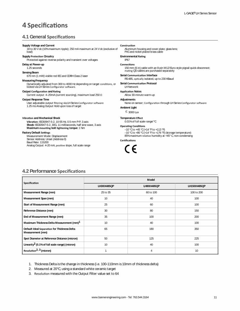
4.2 Performance Specifications
SpecificationModel
LH30IX485QP LH80IX485QP LH150IX485QP
Measurement Range (mm) 25 to 35 60 to 100 100 to 200
Measurement Span (mm) 10 40 100
Start of Measurement Range (mm) 25 60 100
Reference Distance (mm) 30 80 150
End of Measurement Range (mm) 35 100 200
Maximum Thickness Delta Measurement (mm)1 10 40 100
Default Ideal Separation for Thickness DeltaMeasurement (mm)
65 180 350
Spot Diameter at Reference Distance (micron) 50 125 225
Linearity2 (0.1% of full scale range) (micron) 10 40 100
Resolution2, 3 (micron) 1 4 10
1. Thickness Delta is the change in thickness (i.e. 100-110mm is 10mm of thickness delta)2. Measured at 20°C, using a standard white ceramic target3. Resolution measured with the Output Filter value set to 64
L-GAGE® LH Series Sensor
www.bannerengineering.com - Tel: 763.544.3164 11
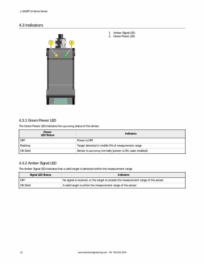
4.3 Indicators
1. Amber Signal LED2. Green Power LED
4.3.1 Green Power LEDThe Green Power LED indicates the operating status of the sensor.
PowerLED Status Indicates
OFF Power is OFF
Flashing Target detected in middle 5% of measurement range
ON Solid Sensor is operating normally (power is ON, Laser enabled)
4.3.2 Amber Signal LEDThe Amber Signal LED indicates that a valid target is detected within the measurement range.
Signal LED Status Indicates
OFF No signal is received, or the target is outside the measurement range of the sensor
ON Solid A valid target is within the measurement range of the sensor
L-GAGE® LH Series Sensor
12 www.bannerengineering.com - Tel: 763.544.3164
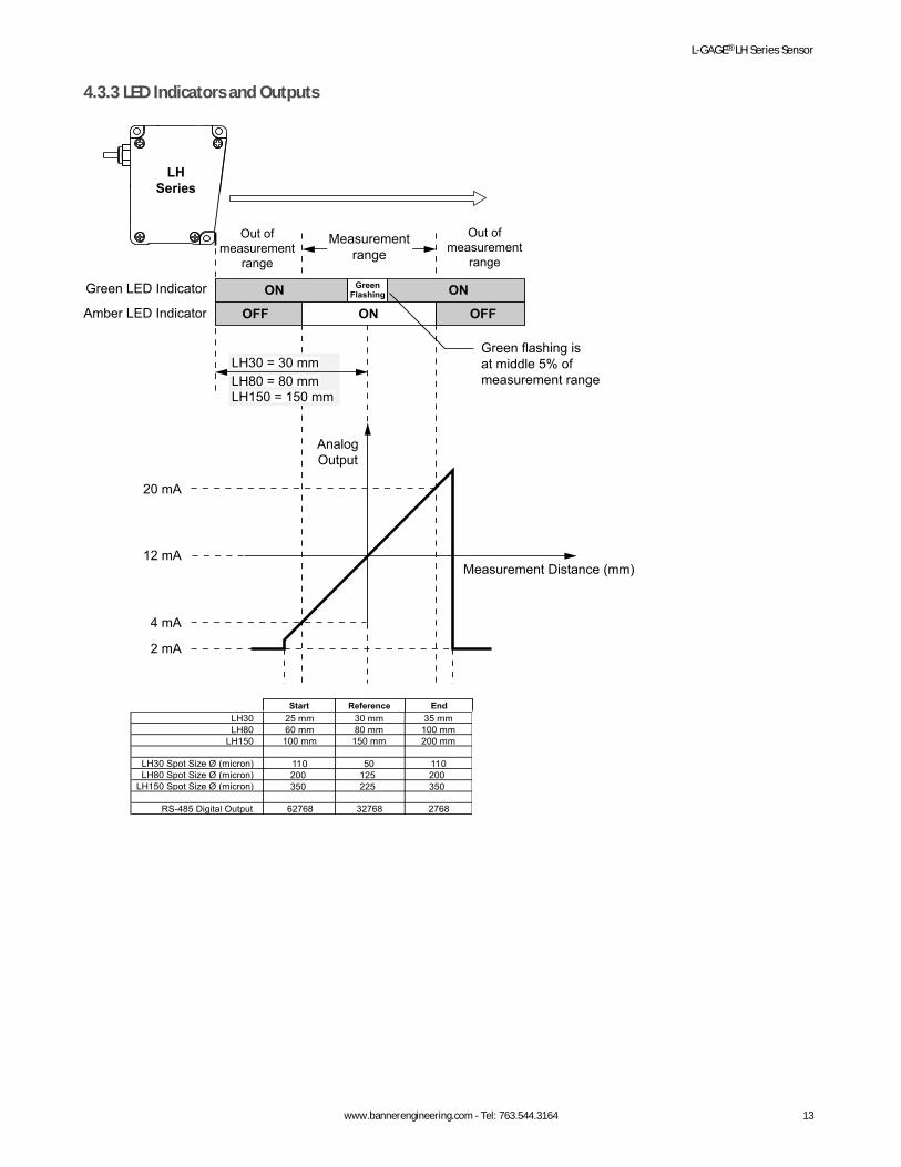
4.3.3 LED Indicators and Outputs
Out ofmeasurement
range
Out ofmeasurement
range
Measurement Distance (mm)
GreenFlashingON ON
ONOFF OFF
Green LED Indicator
Amber LED Indicator
AnalogOutput
Measuringrange
Measurementrange
LH30 25 mm 30 mm 35 mmLH80 60 mm 80 mm 100 mm
LH150 100 mm 150 mm 200 mm
LH30 Spot Size Ø (micron) 110 50 110LH80 Spot Size Ø (micron) 200 125 200
LH150 Spot Size Ø (micron) 350 225 350
RS-485 Digital Output 62768 32768 2768
20 mA
12 mA
4 mA
2 mA
LHSeries
LH30 = 30 mmLH80 = 80 mmLH150 = 150 mm
Green flashing isat middle 5% ofmeasurement range
Start Reference End
L-GAGE® LH Series Sensor
www.bannerengineering.com - Tel: 763.544.3164 13
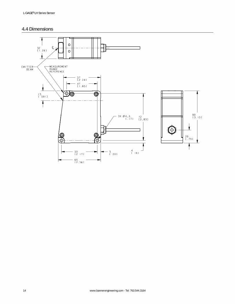
4.4 Dimensions
L-GAGE® LH Series Sensor
14 www.bannerengineering.com - Tel: 763.544.3164
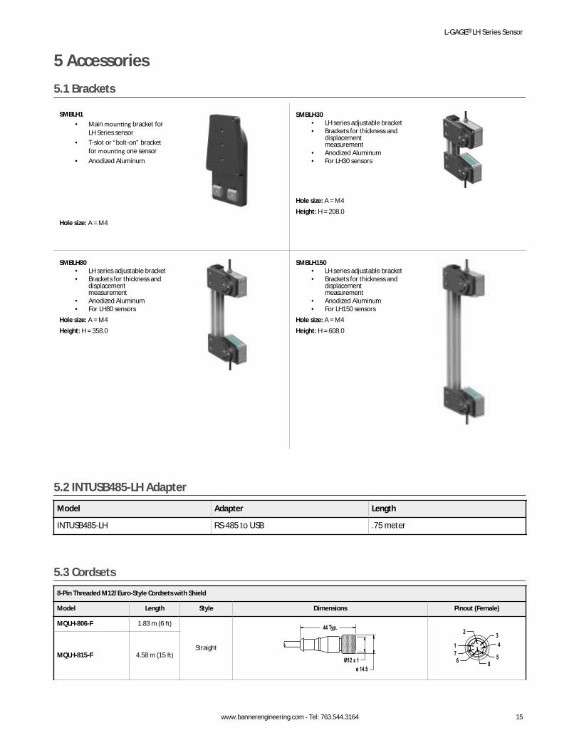
5 Accessories5.1 Brackets
SMBLH1• Main mounting bracket for
LH Series sensor• T-slot or “bolt-on” bracket
for mounting one sensor• Anodized Aluminum
Hole size: A = M4
SMBLH30• LH series adjustable bracket• Brackets for thickness and
displacementmeasurement
• Anodized Aluminum• For LH30 sensors
Hole size: A = M4Height: H = 208.0
SMBLH80• LH series adjustable bracket• Brackets for thickness and
displacementmeasurement
• Anodized Aluminum• For LH80 sensors
Hole size: A = M4Height: H = 358.0
SMBLH150• LH series adjustable bracket• Brackets for thickness and
displacementmeasurement
• Anodized Aluminum• For LH150 sensors
Hole size: A = M4Height: H = 608.0
5.2 INTUSB485-LH Adapter
Model Adapter Length
INTUSB485-LH RS-485 to USB .75 meter
5.3 Cordsets8-Pin Threaded M12/Euro-Style Cordsets with Shield
Model Length Style Dimensions Pinout (Female)
MQLH-806-F 1.83 m (6 ft)
Straight
44 Typ.
ø 14.5M12 x 1 5
432
8
176
MQLH-815-F 4.58 m (15 ft)
L-GAGE® LH Series Sensor
www.bannerengineering.com - Tel: 763.544.3164 15
8-Pin Threaded M12/Euro-Style Cordsets with Shield
Model Length Style Dimensions Pinout (Female)
MQLH-830-F 9.14 m (30 ft)
1 = White2 = Brown3 = Shield4 = Yellow
5 = Gray6 = Green7 = Blue
8 = Shield
8-Pin Threaded M12/Euro-Style Cordsets with Shield―Double Ended
Model Length Style Dimensions Pinout
MQLH-806-MF 1.83 m (6 ft)
Male Straight/Female Straight
40 Typ.
ø 14.5M12 x 1
44 Typ.
ø 14.5M12 x 1
Female
5
432
8
176
Male
5
671
8
234
MQLH-815-MF 4.57 m (15 ft)
MQLH-830-MF 9.14 m (30 ft)
MQLH-801-MM 0.30 m (1 ft) Male Straight/Male Straight
M12 x 1
ø 14.5
M12 x 1
ø 14.5
40 mmmax.
40 mmmax.
1 = White2 = Brown3 = Shield4 = Yellow
5 = Gray6 = Green7 = Blue
8 = Shield
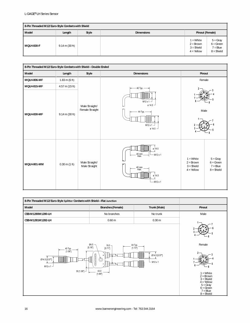
8-Pin Threaded M12/Euro-Style Splitter Cordsets with Shield—Flat Junction
Model Branches (Female) Trunk (Male) Pinout
CSB-M1280M1280-LH No branches No trunk Male
5
671
8
234
Female
5
432
8
176
1 = White2 = Brown3 = Shield4 = Yellow5 = Gray
6 = Green7 = Blue
8 = Shield
CSB-M1281M1282-LH 0.60 m 0.30 m
44 Typ.[1.73"]
43.0[1.69"]
Ø14.5 [0.57"]
M12 x 1Ø14.5 [0.57"]
40 Typ. [1.58"]
18.0[0.71"]
Ø4.5[0.18"]
35 [1.38"]
M12 x 1
L-GAGE® LH Series Sensor
16 www.bannerengineering.com - Tel: 763.544.3164
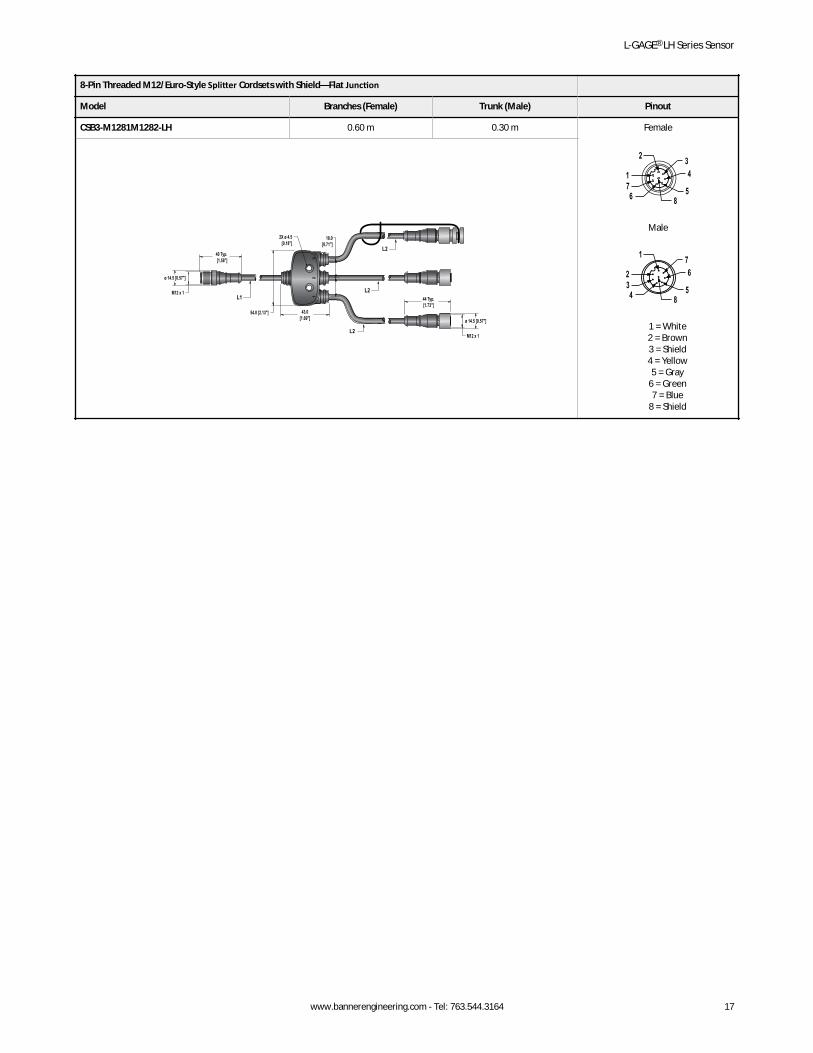
8-Pin Threaded M12/Euro-Style Splitter Cordsets with Shield—Flat Junction
Model Branches (Female) Trunk (Male) Pinout
CSB3-M1281M1282-LH 0.60 m 0.30 m Female
5
432
8
176
Male
5
671
8
234
1 = White2 = Brown3 = Shield4 = Yellow5 = Gray
6 = Green7 = Blue
8 = Shield
12
3
44 Typ.[1.73"]
43.0[1.69"] ø 14.5 [0.57"]
M12 x 1
ø 14.5 [0.57"]
40 Typ. [1.58"]
18.0[0.71"]
2X ø 4.5[0.18"]
54.0 [2.13"]
M12 x 1
L2
L2
L2
L1
L-GAGE® LH Series Sensor
www.bannerengineering.com - Tel: 763.544.3164 17
6 Banner Engineering Corp. Limited WarrantyBanner Engineering Corp. warrants its products to be free from defects in material and workmanship for one year following the date of shipment. Banner Engineering Corp. will repair orreplace, free of charge, any product of its manufacture which, at the time it is returned to the factory, is found to have been defective during the warranty period. This warranty does not coverdamage or liability for misuse, abuse, or the improper application or installation of the Banner product.THIS LIMITED WARRANTY IS EXCLUSIVE AND IN LIEU OF ALL OTHER WARRANTIES WHETHER EXPRESS OR IMPLIED (INCLUDING, WITHOUT LIMITATION, ANY WARRANTY OFMERCHANTABILITY OR FITNESS FOR A PARTICULAR PURPOSE), AND WHETHER ARISING UNDER COURSE OF PERFORMANCE, COURSE OF DEALING OR TRADE USAGE.This Warranty is exclusive and limited to repair or, at the discretion of Banner Engineering Corp., replacement. IN NO EVENT SHALL BANNER ENGINEERING CORP. BE LIABLE TO BUYER OR ANYOTHER PERSON OR ENTITY FOR ANY EXTRA COSTS, EXPENSES, LOSSES, LOSS OF PROFITS, OR ANY INCIDENTAL, CONSEQUENTIAL OR SPECIAL DAMAGES RESULTING FROM ANY PRODUCTDEFECT OR FROM THE USE OR INABILITY TO USE THE PRODUCT, WHETHER ARISING IN CONTRACT OR WARRANTY, STATUTE, TORT, STRICT LIABILITY, NEGLIGENCE, OR OTHERWISE.Banner Engineering Corp. reserves the right to change, modify or improve the design of the product without assuming any obligations or liabilities relating to any product previouslymanufactured by Banner Engineering Corp. Any misuse, abuse, or improper application or installation of this product or use of the product for personal protection applications when theproduct is identified as not intended for such purposes will void the product warranty. Any modifications to this product without prior express approval by Banner Engineering Corp will void theproduct warranties. All specifications published in this document are subject to change; Banner reserves the right to modify product specifications or update documentation at any time.Specifications and product information in English supersede that which is provided in any other language. For the most recent version of any documentation, refer to: www.bannerengineering.com.
6.1 Contact UsCorporate Headquarters
Address:Banner Engineering Corporate9714 Tenth Avenue NorthMinneapolis, Minnesota 55441, USA
Phone: +1 763 544 3164Website: www.bannerengineering.com
Europe
Address:Banner Engineering EMEAPark Lane Culliganlaan 2FDiegem B-1831, Belgium
Phone: +32 (0)2 456 0780Website: www.bannerengineering.com/euEmail: [email protected]
Turkey
Address:Banner Engineering TurkeyBarbaros Mah. Uphill Court Towers A Blok D:4934746 Batı Ataşehir Istanbul Türkiye
Phone: +90 216 688 8282Website: www.bannerengineering.com.trEmail: [email protected]
India
Address:Banner Engineering India Pune Head QuartersOffice No. 1001, 10th Floor Sai Capital, Opp. ICC Senapati Bapat RoadPune 411016, India
Phone: +91 (0) 206 640 5624Website: www.bannerengineering.co.inEmail: [email protected]
Mexico
Address:Banner Engineering de Mexico Monterrey Head OfficeEdificio VAO Av. David Alfaro Siqueiros No.103 Col. Valle Oriente C.P.66269San Pedro Garza Garcia, Nuevo Leon, Mexico
Phone: +52 81 8363 2714 or 01 800 BANNERE (toll free)Website: www.bannerengineering.com.mxEmail: [email protected]
Brazil
Address:Banner do BrasilRua Barão de Teffé nº 1000, sala 54Campos Elíseos, Jundiaí - SP, CEP.: 13208-761, Brasil
Phone: +1 763 544 3164Website: www.bannerengineering.com.brEmail: [email protected]
China
Address:Banner Engineering Shanghai Rep OfficeXinlian Scientific Research Building Level 12, Building 21535 Hongmei Road, Shanghai 200233, China
Phone: +86 212 422 6888Website: www.bannerengineering.com.cnEmail: [email protected]
L-GAGE® LH Series Sensor
18 www.bannerengineering.com - Tel: 763.544.3164

Japan
Address:Banner Engineering JapanCent-Urban Building 305 3-23-15 Nishi-Nakajima Yodogawa-KuOsaka 532-0011, Japan
Phone: +81 (0)6 6309 0411Website: www.bannerengineering.co.jpEmail: [email protected]
Taiwan
Address:Banner Engineering Taiwan8F-2, No. 308 Section 1, Neihu RoadTaipei 114, Taiwan
Phone: +886 (0)2 8751 9966Website: www.bannerengineering.com.twEmail: [email protected]
L-GAGE® LH Series Sensor
www.bannerengineering.com - Tel: 763.544.3164 19