Embed Size (px)
Citation preview
High Line Canal,
Cherry Hills Village Irrigation Pilot Study
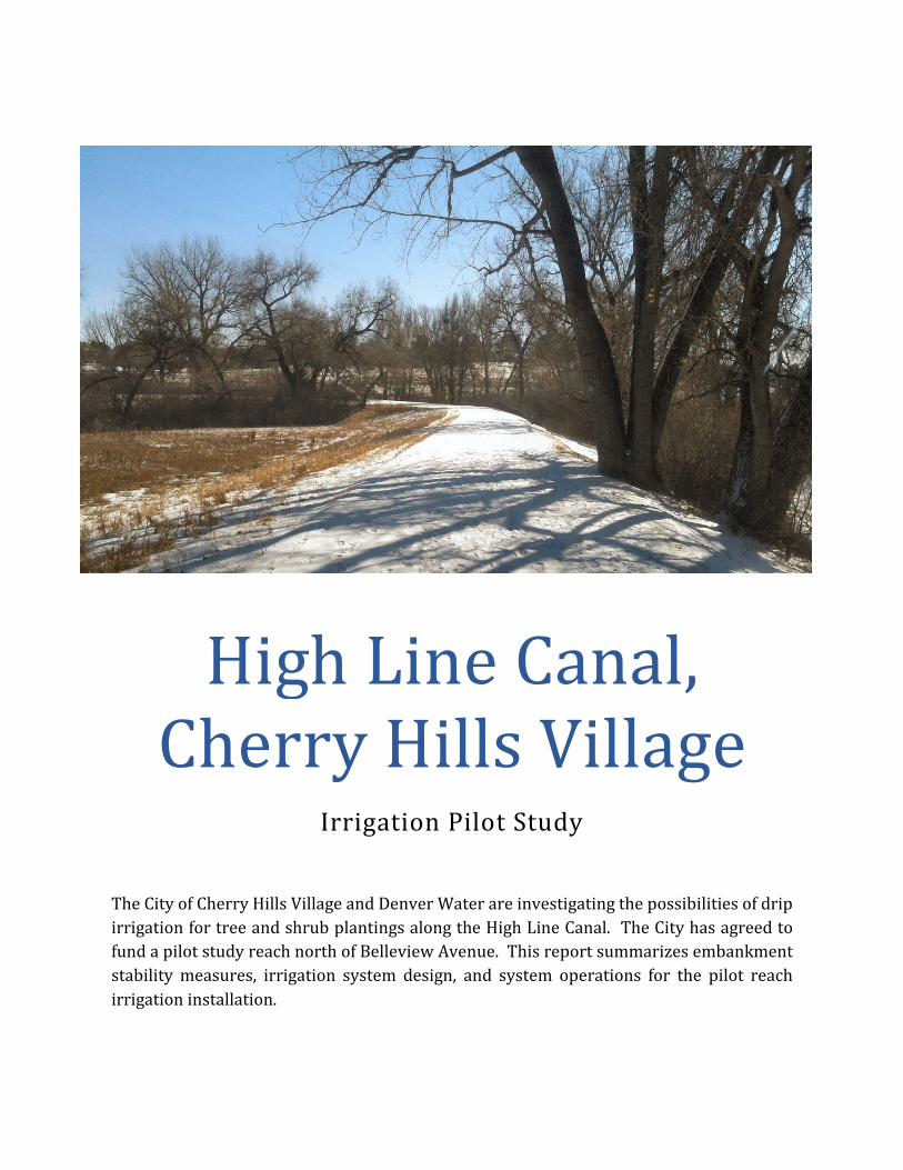
The City of Cherry Hills Village and Denver Water are investigating the possibilities of drip
irrigation for tree and shrub plantings along the High Line Canal. The City has agreed to
fund a pilot study reach north of Belleview Avenue. This report summarizes embankment
stability measures, irrigation system design, and system operations for the pilot reach
irrigation installation.
High Line Canal, Cherry Hills Village
• • •
p:\p\12007chv\12007030 - high line irrigation\docs\report hlc-chv.docx � 1
High Line Canal, Cherry Hills Village
Irrigation Pilot Study
Contents
Introduction .......................................................................................................................................................................................... 2
Embankment Stability .......................................................................................................................................2
Irrigation Design ................................................................................................................................................................................. 3
Operations ............................................................................................................................................................................................. 4
Conclusion ............................................................................................................................................................4
Appendex ............................................................................................................................................................................................... 5
High Line Canal, Cherry Hills Village
• • •
p:\p\12007chv\12007030 - high line irrigation\docs\report hlc-chv.docx � 2
Introduction
ICON has completed the Irrigation Pilot Study for the High Line Canal. The study includes
Embankment Stability, Irrigation Design and Operations. The Embankment Stability includes the
alignment, trench design, max failure analysis and varmit protection. The Irrigation Design
consists of a bubbler based irrigating system for newly planted trees. The Operation of the system
will include regular maintenance, observation, and operation task completed by City Staff.
Embankment Stability
The pilot reach includes several design elements intended to maximize stability of the
embankment in the unlikely event of an irrigation system failure.
Alignment: The irrigation line is intentionally aligned at the landside crest or toe to provide the
maximum undisturbed embankment for the hydraulic loads from the canal. As shown in the cross
sections, this alignment provides horizontal and vertical clearance to the hydraulic loads in the
canal.
Max failure analysis. Estimation of the max potential energy from a pipe failure leads to a
maximum potential failure volume for any given irrigation zone in the pilot reach. This is based
upon limited irrigation zone lengths which limit the volume of water in any given leak. This is
based upon gross assumptions of single point, instantaneous, full volume leak impacting native
soils without any trench protection. The result of this analysis indicates there is a minor
percentage of the embankment that is threatened should a pressurized failure occur.
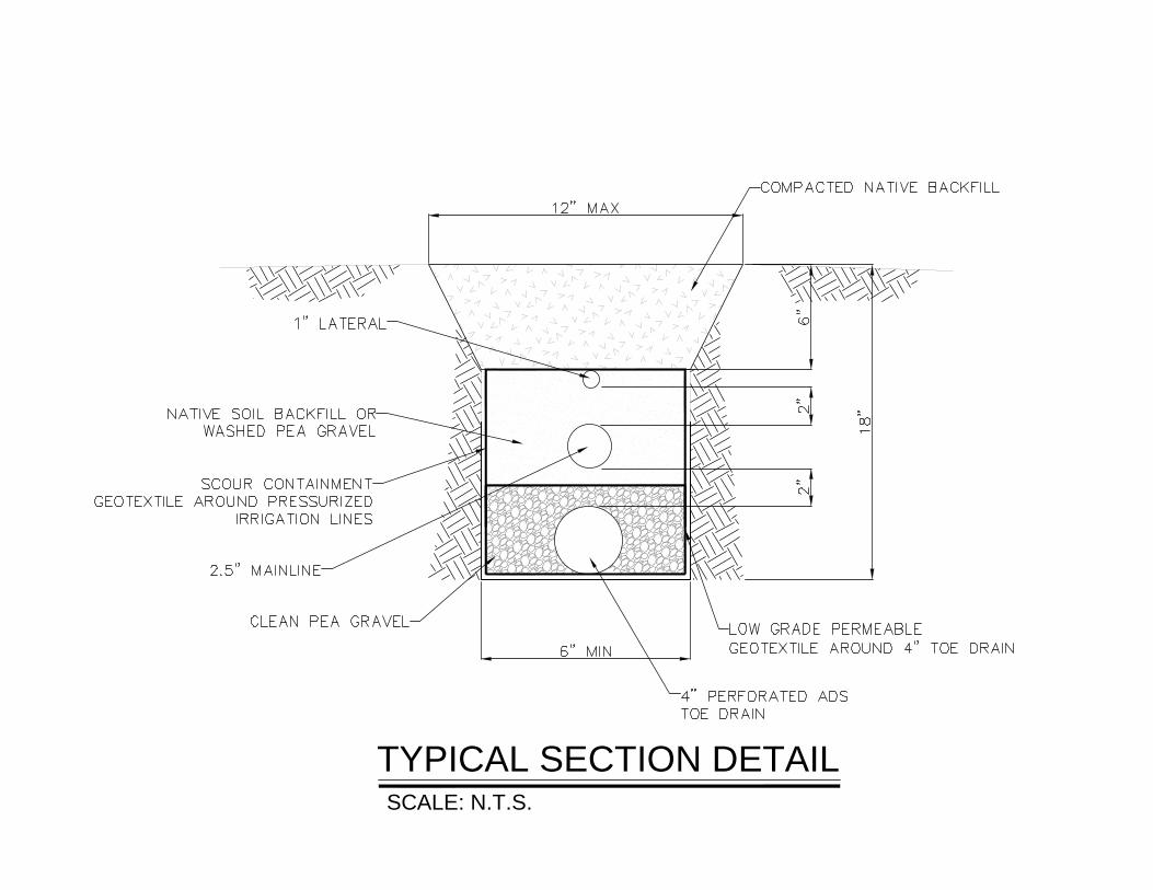
Trench design: To protect against the highly unlikely event assumed in the max failure analysis,
the trench design includes several redundant measures to protect the embankment: single trench
installation, scour arresting geotextile, and an underdrain. The single trench installation
minimizes the footprint of disturbed soil within the embankment. The scour arresting geotextile
secures any breach of the pressurized system within the self-compacting, non-consolidating,
highly permeable washed gravel backfill within the engineered trench section. The underdrain
releases the break water in a slow, controlled, and identifiable location. All of these elements
combine to ensure that any break in the pressurized system does not impact the embankment, is
quickly identified, and easily repaired.
Varmit protection: The valve boxes and underdrain daylight locations are secured to prevent
varmit intrusion. Valve box lids will be sealed with silicone and underdrain outlets will be fitted
with grates. Further, pest control professionals will be consulted to include proper varmit poisons
High Line Canal, Cherry Hills Village
• • •
p:\p\12007chv\12007030 - high line irrigation\docs\report hlc-chv.docx � 3
within the valve boxes to ensure any burrowing pest that does enter the system is not provided a
sustainable hostel.
Irrigation Design
The proposed irrigation system will consist of a bubbler-based system irrigating newly planted
trees. Each tree will have a single 0.5 gallon per minute bubbler. All trees will be located on the
west side of the Highline Canal Trail.
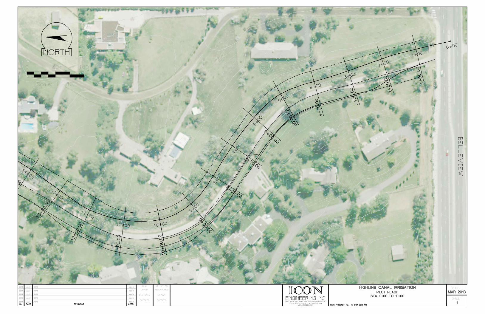
The proposed irrigation system will originate from an existing Cherry Hills Village irrigation
mainline at intersection of Belleview Ave. and the Highline Canal. From its connection to the
existing mainline the new mainline will extend approximately 1000 linear feet in a northerly
direction as part of the Phase 1 project limits.
Electric irrigation valves will control water flow to the individual zones that irrigate the trees.
Expected flows will be in the 10-20 gpm range. Only one valve will be in operation at any given
time during an irrigation cycle.
The system will be controlled via an irrigation controller. The control system will incorporate a
flow sensor and master valve at the origination point for the new mainline.
The flow sensor and master valve provide a method of monitoring flow rates and act as a safety
system for the irrigation system. If excessive flow or unauthorized flow is detected by the flow
sensor (indicating a problem with the system), the controller will deactivate (close) the master
valve and shut-down water to the entire system. The normally closed master valve (i.e. valve is in
closed position unless activated/opened by the controller during an irrigation cycle) will provide
another safety device during times when the irrigation system is not operating as the valve
remains closed and prohibits water from flowing in the new mainline. Additionally, a rain sensor
will be installed at the controller location. The rain sensor will be another safety device to ensure
irrigation does not occur during or immediately after a rain event.
It is proposed that the irrigation system be operated during day hours, in contrast to typically
recommended night hours watering. As the bubbler system will incur minimal evaporative water
losses, the day time watering schedule day time operation will allow the trail users to be
additional sets of eyes to notice any malfunctions (broken lines, missing bubbler nozzles, etc.) and
to notify Cherry Hills Village of these problems.
High Line Canal, Cherry Hills Village
• • •
p:\p\12007chv\12007030 - high line irrigation\docs\report hlc-chv.docx � 4
Lastly, estimated quantities of major irrigation equipment and materials for the test site will
include: 1) 1000 l.f. 2” PVC mainline, 2) 750 l.f. 1” PVC lateral piping, 3) two electric valves, 4) one
master valve, 5) one flow sensor, 6) one electric controller with rain sensor,, 7) three quick
coupling valves, 8) one pressure reducing valve, 8) 1000 l.f. two-wire cable, 9) twenty bubblers
and 10) two gate valves.
Operations
The Cherry Hills Village Staff will have a standard operating procedure in place for morning and
afternoon line inspections during the irrigation season (April-October). It will be expected that
City staff will inspect the test section once or twice per week, depending on the amount of time
irrigation is running to the planted trees.
Irrigation restrictions: Cherry Hills Village will agree to shut down the main irrigation system
valve during times where the High Line Canal is running water. Doing this will ensure there is no
threat to the embankment when the failure risk is highest. This restriction will be documented in
a standard operating procedure.
Leak detection: Cherry Hills Village staff will periodically (up to twice per week) visually inspect
irrigation system. Additionally, Cherry Hills Village will place signage along the trail to inform
users of the canal that there is live irrigation that has the potential to break and/or leak. The signs
will provide trail users a hotline phone number to report leaks or other concerns with the
irrigation system that will be installed along the pilot reach.
Conclusion
The City of Cherry Hills Village seeks authorization from the Denver Water Department Recreation
Division for April 2013 installation of the irrigation system proposed in the Pilot Reach shown in
the appendix. The City and Denver Water will monitor the pilot reach for the 2013 irrigation
season. In November 2013, the City will submit to Denver Water a follow-up report detailing the
results of the pilot reach operations.
High Line Canal, Cherry Hills Village
• • •
p:\p\12007chv\12007030 - high line irrigation\docs\report hlc-chv.docx � 5
Appendix
Plan View
Cross Sections
Trench Cross Section A
Trench Cross Section B
ICON
SCALE: N.T.S.
TYPICAL SECTION DETAIL
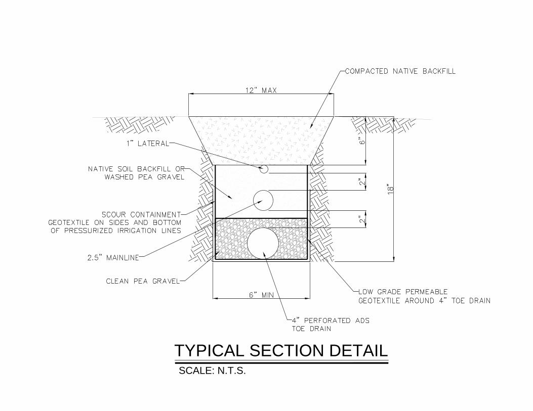
SCALE: N.T.S.
TYPICAL SECTION DETAIL
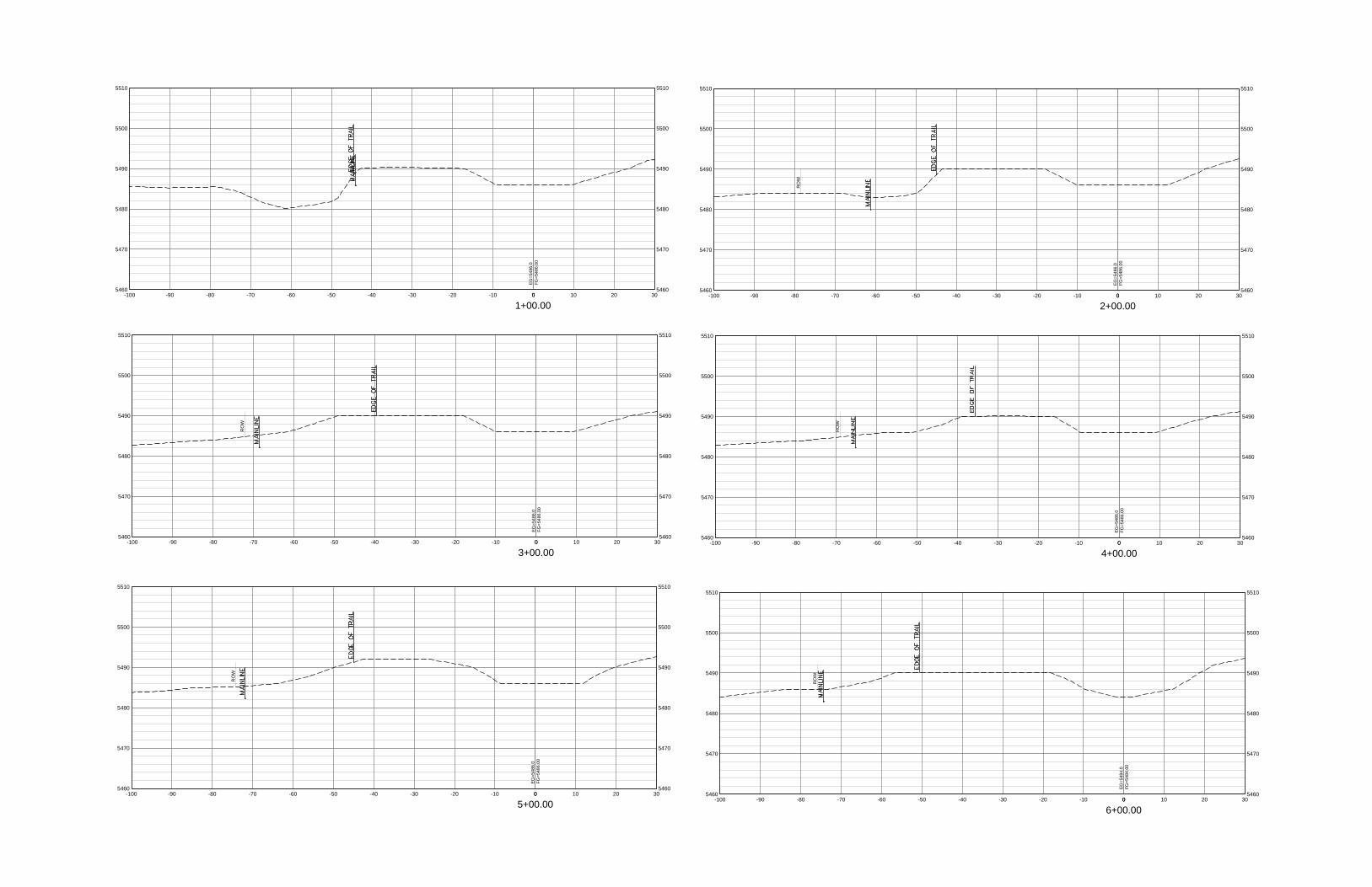
1+00.00
5460
5470
5480
5490
5500
5510
5460
5470
5480
5490
5500
5510
0 10 20 300-10-20-30-40-50-60-70-80-90-100
EG
=548
6.0
FG=5
486.
00
2+00.00
5460
5470
5480
5490
5500
5510
5460
5470
5480
5490
5500
5510
0 10 20 300-10-20-30-40-50-60-70-80-90-100
RO
W
EG
=548
6.0
FG=5
486.
00
4+00.00
5460
5470
5480
5490
5500
5510
5460
5470
5480
5490
5500
5510
0 10 20 300-10-20-30-40-50-60-70-80-90-100
RO
W
EG
=548
6.0
FG=5
486.
00
3+00.00
5460
5470
5480
5490
5500
5510
5460
5470
5480
5490
5500
5510
0 10 20 300-10-20-30-40-50-60-70-80-90-100
RO
W
EG
=548
6.0
FG=5
486.
00
5+00.00
5460
5470
5480
5490
5500
5510
5460
5470
5480
5490
5500
5510
0 10 20 300-10-20-30-40-50-60-70-80-90-100
RO
W
EG
=548
6.0
FG=5
486.
00
6+00.00
5460
5470
5480
5490
5500
5510
5460
5470
5480
5490
5500
5510
0 10 20 300-10-20-30-40-50-60-70-80-90-100
RO
W
EG
=548
4.0
FG=5
484.
00
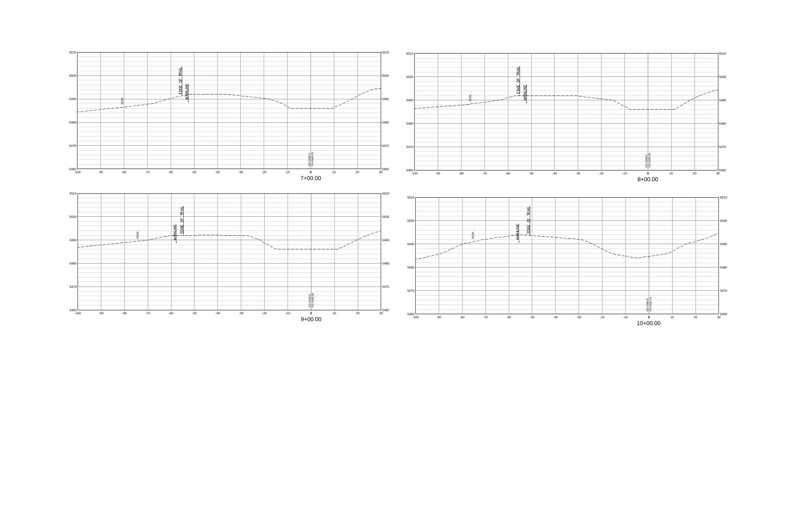
7+00.00
5460
5470
5480
5490
5500
5510
5460
5470
5480
5490
5500
5510
0 10 20 300-10-20-30-40-50-60-70-80-90-100
RO
W
EG
=548
5.9
FG=5
485.
93
8+00.00
5460
5470
5480
5490
5500
5510
5460
5470
5480
5490
5500
5510
0 10 20 300-10-20-30-40-50-60-70-80-90-100
RO
W
EG
=548
6.0
FG=5
485.
99
10+00.00
5460
5470
5480
5490
5500
5510
5460
5470
5480
5490
5500
5510
0 10 20 300-10-20-30-40-50-60-70-80-90-100
RO
W
EG
=548
4.8
FG=5
484.
76
9+00.00
5460
5470
5480
5490
5500
5510
5460
5470
5480
5490
5500
5510
0 10 20 300-10-20-30-40-50-60-70-80-90-100
RO
W
EG
=548
6.0
FG=5
486.
00