Embed Size (px)
Citation preview
1
Light Wood Framing #1
References
• Graphic Guide to FrameConstruction, RobThalon, Taunton Press,29.95
• APA Guide toResidentialConstruction, APA -The Engineered WoodAssociation
• International ResidentialCode, ICC
A Revolution...
• The hand hewing of tree trunks into columns, beamsand bents making up a heavy timber frame has beenthe standard for construction since 2500 B.C.
• But in 1795 Jacob Perkins was issued a patent, andby 1800 the water powered circular saw wasproducing sawn lumber quickly and costeffectively…the patent? An automated nail makingmachine.
2
Old Nails
• Nails had been handmade since beforeRome.
• The Romans mass produced nails by castingmolten metal into square rods, nail stock.
• Up through the colonial era, nail stock was re-heated, cut, and hammered into taperedshapes and flattened at one end (head it off -to end it)
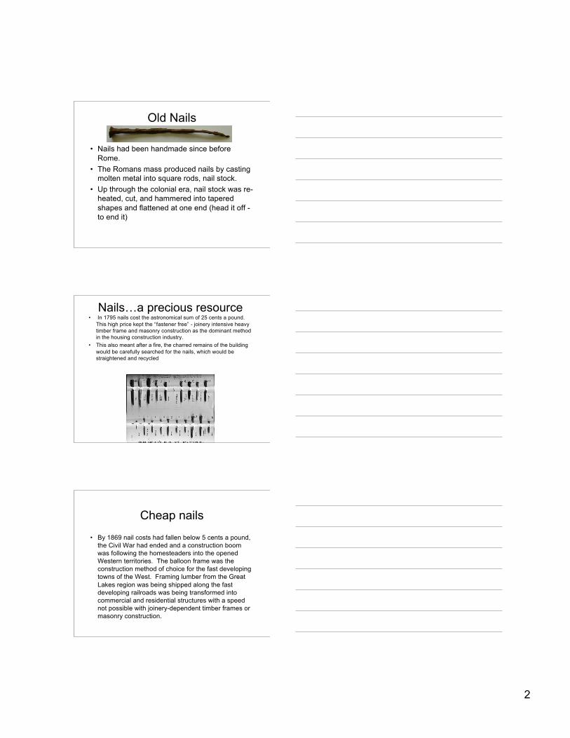
Nails…a precious resource• In 1795 nails cost the astronomical sum of 25 cents a pound.
This high price kept the “fastener free” - joinery intensive heavytimber frame and masonry construction as the dominant methodin the housing construction industry.
• This also meant after a fire, the charred remains of the buildingwould be carefully searched for the nails, which would bestraightened and recycled
Cheap nails
• By 1869 nail costs had fallen below 5 cents a pound,the Civil War had ended and a construction boomwas following the homesteaders into the openedWestern territories. The balloon frame was theconstruction method of choice for the fast developingtowns of the West. Framing lumber from the GreatLakes region was being shipped along the fastdeveloping railroads was being transformed intocommercial and residential structures with a speednot possible with joinery-dependent timber frames ormasonry construction.
3
Pennies per nail
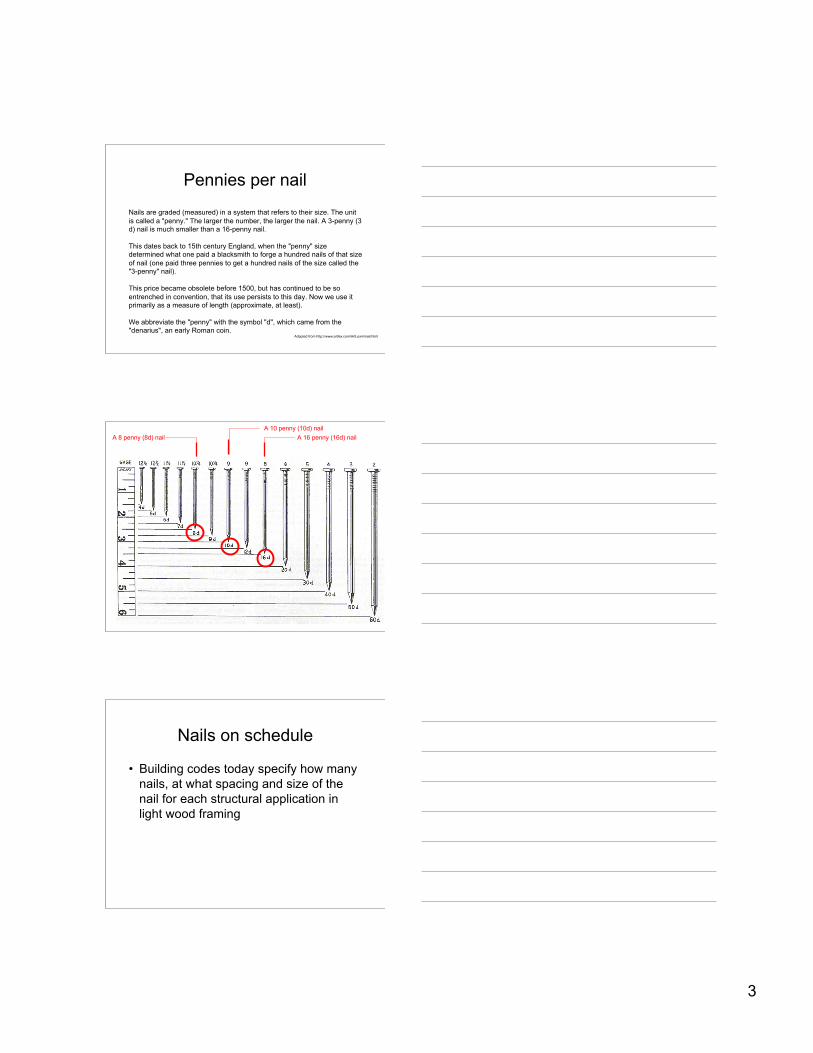
Nails are graded (measured) in a system that refers to their size. The unitis called a "penny." The larger the number, the larger the nail. A 3-penny (3d) nail is much smaller than a 16-penny nail.
This dates back to 15th century England, when the "penny" sizedetermined what one paid a blacksmith to forge a hundred nails of that sizeof nail (one paid three pennies to get a hundred nails of the size called the"3-penny" nail).
This price became obsolete before 1500, but has continued to be soentrenched in convention, that its use persists to this day. Now we use itprimarily as a measure of length (approximate, at least).
We abbreviate the "penny" with the symbol "d", which came from the"denarius", an early Roman coin.
Adapted from http://www.artlex.com/ArtLex/n/nail.html
A 10 penny (10d) nailA 16 penny (16d) nailA 8 penny (8d) nail
Nails on schedule
• Building codes today specify how manynails, at what spacing and size of thenail for each structural application inlight wood framing
4
International Residential CodeNail schedule table R602.3(1)
• Sole plate to joist or blocking 16d @16”o.c.• Top or sole plate to stud, end nail 2 - 16d• Stud to sole plate, toenail 3-8d or 2-16d• Doubled studs, face nailed 10d @ 24”o.c.• Double top plates, face nailed 10d @ 24”o.c.• Sole plate to joist 3-16d@16”o.c.• Blocking at braced wall panels 3-16d@16”o.c.• Double top plates, face nail @ 4’offset ends 8-16d• Blocking between joists or rafters 3-8d• Rim joists to top plate, toenail 8d@6”o.c.• Top plates laps at corners and intersections face nail 2-10d
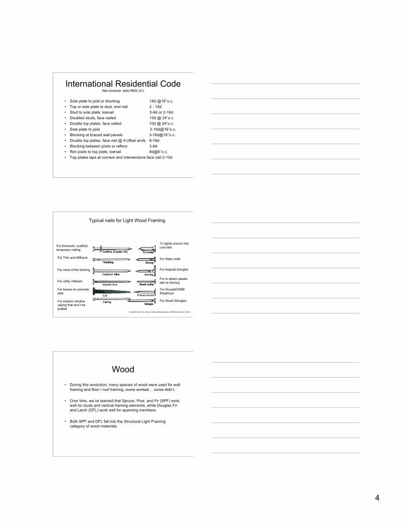
Typical nails for Light Wood Framing
To lightly anchor intoconcrete
For Asphalt shingles
For Slate roofs
For to attach plasterlath to framing
For Drywall/GWB/Sheetrock
For Wood Shingles
For formwork, scaffold,temporary nailing
For Trim and Millwork
For most of the framing
For braces to concreteslab
For exterior windowcasing that won’t beputtied
For utility millwork
Illustration from http://www.constructionworknews.com/field-manual/2-1-0.html
Wood• During this revolution, many species of wood were used for wall
framing and floor / roof framing, some worked… some didn’t.
• Over time, we’ve learned that Spruce, Pine, and Fir (SPF) workwell for studs and vertical framing elements, while Douglas Firand Larch (DFL) work well for spanning members.
• Both SPF and DFL fall into the Structural Light Framingcategory of wood materials.
5
Stress grade lumber… Studsand Verticals
• “Light Framing & Studs” (SPF)– “Construction” grade: used for general framing purposes, graded
for strength and serviceability…not appearance– “Standard” grade: used for general framing purposes, graded for
strength and serviceability…not appearance– “Utility” grade: used for general construction purposes (studding,
blocking…for NON-LOAD BEARING USES ONLY)– “Stud” grade: usually for wall framing, may be precut to stud length
Stress grade… Spanninggrades
• “Structural Light Framing” (DFL) For Engineered (spanning)applications– Select Structural used where highest strength (67% of allowable
fiber bending stress for clear lumber) and stiffness & goodappearance are required.
– No. 1 high strength (55% of allowable fiber bending stress for clearlumber) and stiffness and good appearance
– No. 2 (45% of allowable fiber bending stress for clear lumber) andstiffness … recommended for most general construction uses
– No. 3 25% of allowable fiber bending stress for clear lumber andstiffness … recommended for most general construction useswhere appearance is not a factor
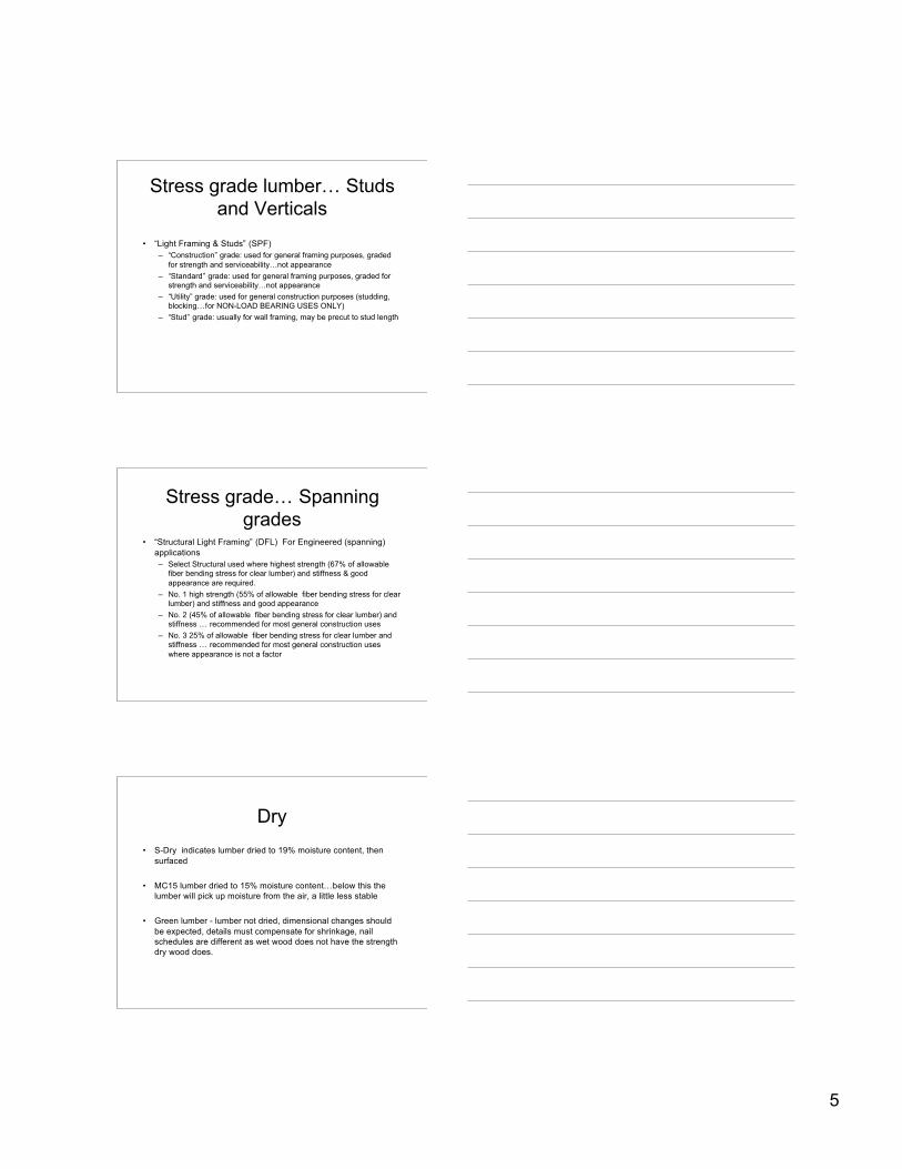
Dry• S-Dry indicates lumber dried to 19% moisture content, then
surfaced
• MC15 lumber dried to 15% moisture content…below this thelumber will pick up moisture from the air, a little less stable
• Green lumber - lumber not dried, dimensional changes shouldbe expected, details must compensate for shrinkage, nailschedules are different as wet wood does not have the strengthdry wood does.
6
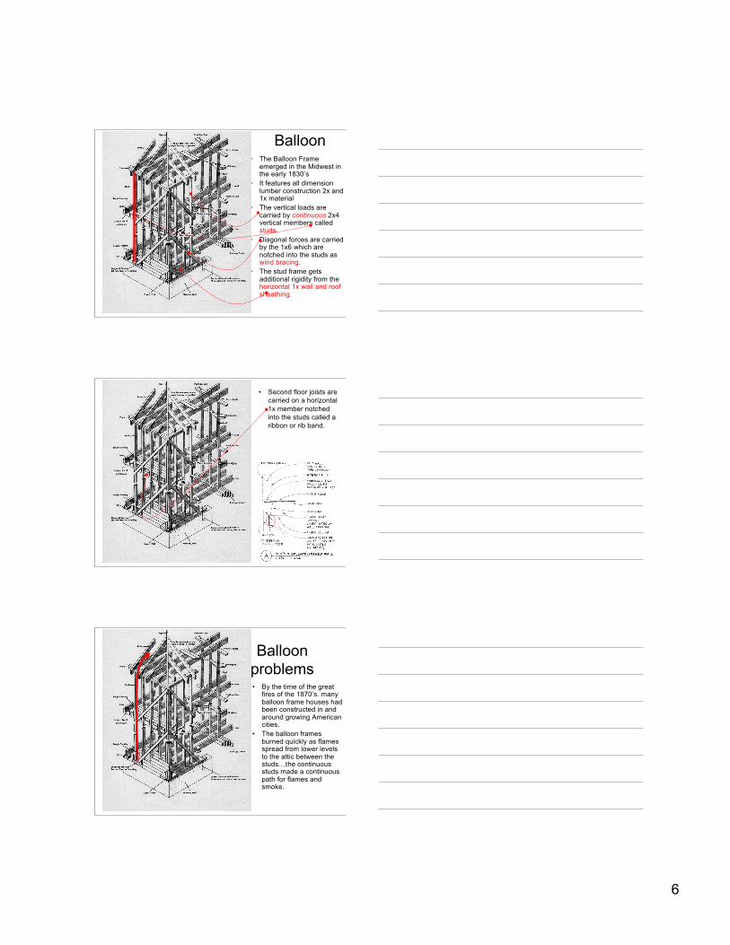
Balloon• The Balloon Frame
emerged in the Midwest inthe early 1830’s
• It features all dimensionlumber construction 2x and1x material
• The vertical loads arecarried by continuous 2x4vertical members calledstuds.
• Diagonal forces are carriedby the 1x6 which arenotched into the studs aswind bracing.
• The stud frame getsadditional rigidity from thehorizontal 1x wall and roofsheathing.
• Second floor joists arecarried on a horizontal1x member notchedinto the studs called aribbon or rib band.
Balloonproblems• By the time of the great
fires of the 1870’s. manyballoon frame houses hadbeen constructed in andaround growing Americancities.
• The balloon framesburned quickly as flamesspread from lower levelsto the attic between thestuds…the continuousstuds made a continuouspath for flames andsmoke.
7
Fire blocks
• Even though we don’t balloon frame much today, anyplace in the light wood frame where a horizontalspace between framing meets a vertical spacebetween framing, there must be at least 1 1/2 inchesof solid wood cut to precisely fit between the framingand prevent smoke and fire from moving throughcontinuous vertical or horizontal spaces betweenframing
• The code requires fire blocking in framing spaces atleast every 10 feet, either horizontally or vertically.
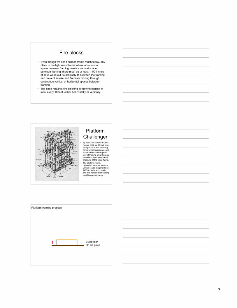
PlatformChallenger
• By 1900, the balloon frameshungry habit for 19 foot longstraight 2x4’s was strainingsome lumber producers, andsome builders developed away of framing small housesto address the flamespreadproblems of the wood frame.
• The platform frame,depended on studs to carryvertical loads, diagonal let in1x6’s to resist wind loads,and 1x6 horizontal sheathingto stiffen up the frame.
Build floorOn sill plate
1
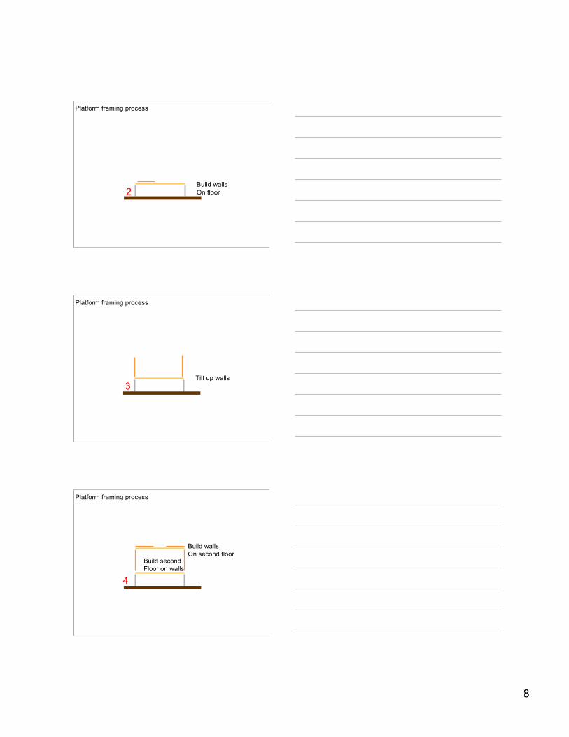
Platform framing process
8
Build wallsOn floor2
Platform framing process
Tilt up walls3
Platform framing process
Build secondFloor on walls
Build wallsOn second floor
4
Platform framing process
9
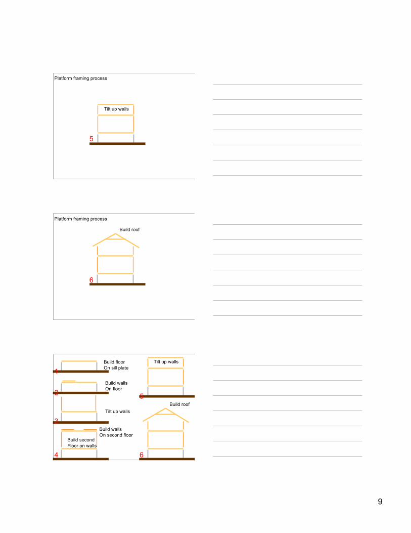
Tilt up walls
5
Platform framing process
Build roof
6
Platform framing process
Build floorOn sill plate
Build wallsOn floor
Tilt up walls
Build secondFloor on walls
Build wallsOn second floor
Tilt up walls
Build roof
1
2
3
4
5
6
10
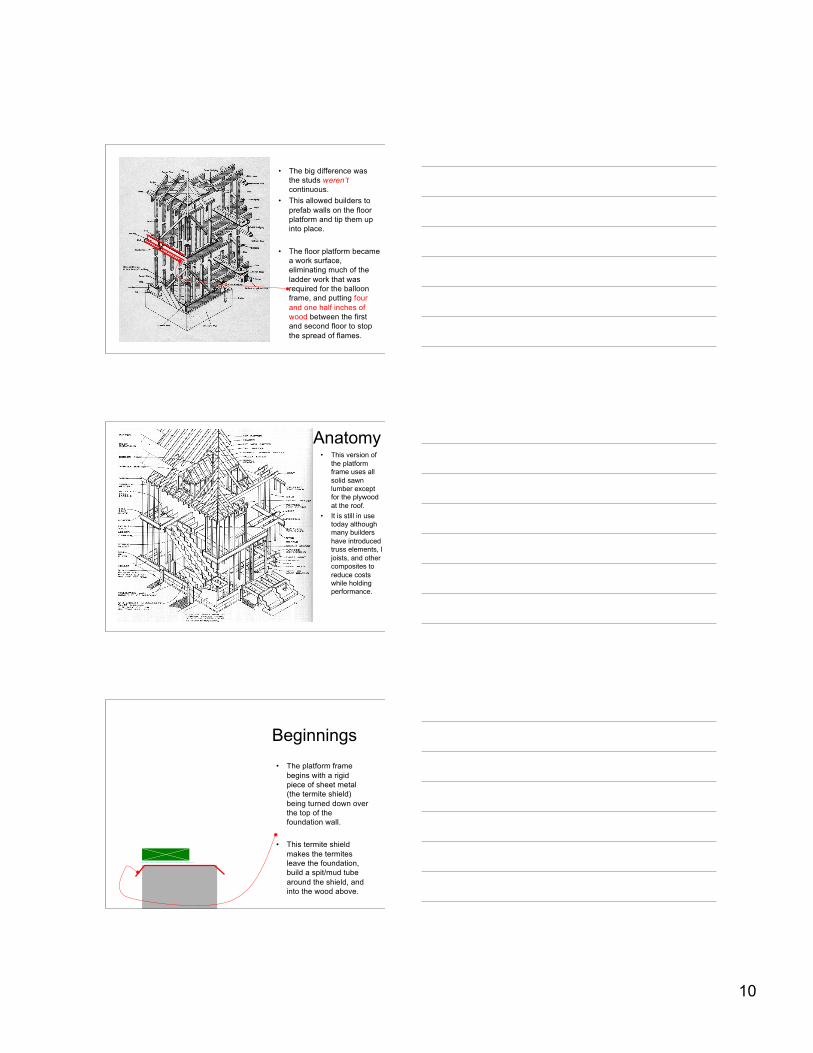
• The big difference wasthe studs weren’tcontinuous.
• This allowed builders toprefab walls on the floorplatform and tip them upinto place.
• The floor platform becamea work surface,eliminating much of theladder work that wasrequired for the balloonframe, and putting fourand one half inches ofwood between the firstand second floor to stopthe spread of flames.
Anatomy• This version of
the platformframe uses allsolid sawnlumber exceptfor the plywoodat the roof.
• It is still in usetoday althoughmany buildershave introducedtruss elements, Ijoists, and othercomposites toreduce costswhile holdingperformance.
Beginnings• The platform frame
begins with a rigidpiece of sheet metal(the termite shield)being turned down overthe top of thefoundation wall.
• This termite shieldmakes the termitesleave the foundation,build a spit/mud tubearound the shield, andinto the wood above.
11
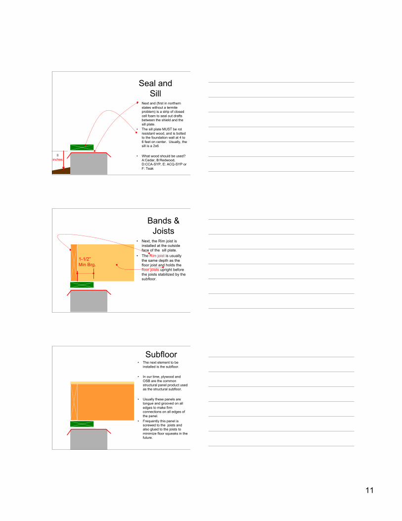
Seal andSill
• Next and (first in northernstates without a termiteproblem) is a strip of closedcell foam to seal out draftsbetween the shield and thesill plate.
• The sill plate MUST be rotresistant wood, and is boltedto the foundation wall at 4 to6 feet on center. Usually, thesill is a 2x6
• What wood should be used?A:Cedar, B:Redwood,D:CCA-SYP, E: ACQ-SYP orF: Teak
8inches
Bands &Joists
• Next, the Rim joist isinstalled at the outsideface of the sill plate.
• The Rim joist is usuallythe same depth as thefloor joist and holds thefloor joists upright beforethe joists stabilized by thesubfloor.
1-1/2”Min Brg.
Subfloor• The next element to be
installed is the subfloor.
• In our time, plywood andOSB are the commonstructural panel product usedas the structural subfloor.
• Usually these panels aretongue and grooved on alledges to make firmconnections on all edges ofthe panel.
• Frequently this panel isscrewed to the joists andalso glued to the joists tominimize floor squeaks in thefuture.
12
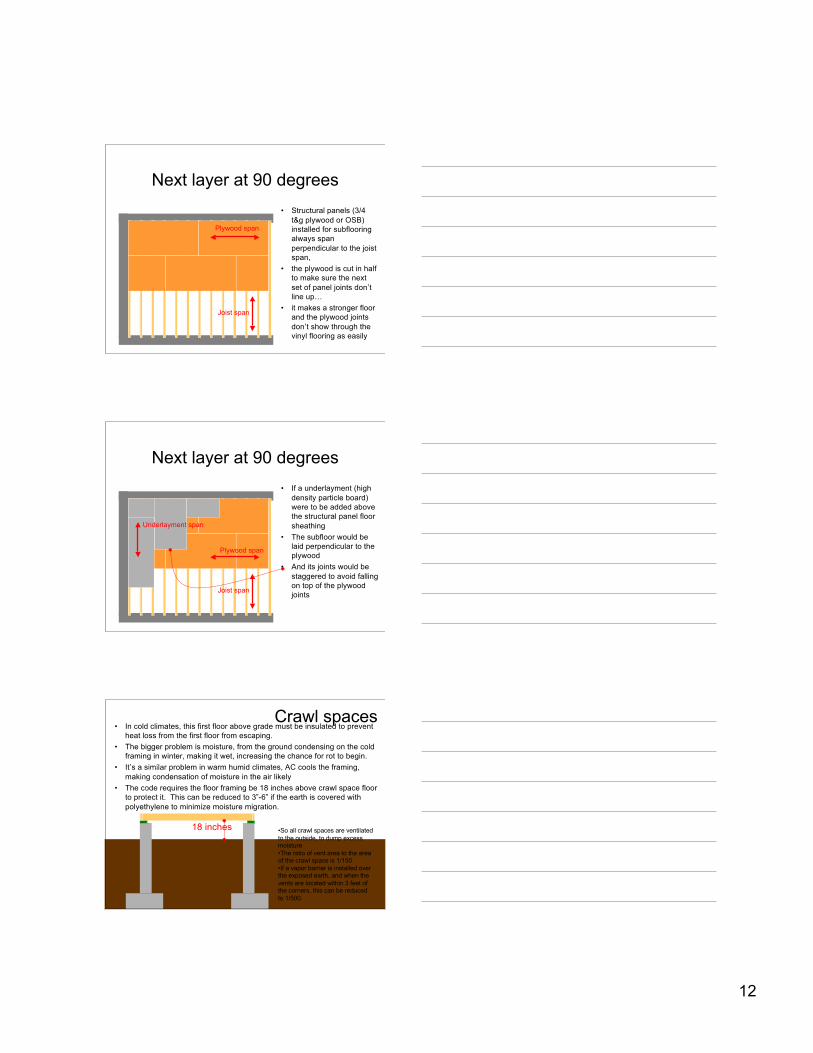
Next layer at 90 degrees• Structural panels (3/4
t&g plywood or OSB)installed for subflooringalways spanperpendicular to the joistspan,
• the plywood is cut in halfto make sure the nextset of panel joints don’tline up…
• it makes a stronger floorand the plywood jointsdon’t show through thevinyl flooring as easily
Plywood span
Joist span
Next layer at 90 degrees• If a underlayment (high
density particle board)were to be added abovethe structural panel floorsheathing
• The subfloor would belaid perpendicular to theplywood
• And its joints would bestaggered to avoid fallingon top of the plywoodjoints
Plywood span
Joist span
Underlayment span
Crawl spaces• In cold climates, this first floor above grade must be insulated to prevent
heat loss from the first floor from escaping.• The bigger problem is moisture, from the ground condensing on the cold
framing in winter, making it wet, increasing the chance for rot to begin.• It’s a similar problem in warm humid climates, AC cools the framing,
making condensation of moisture in the air likely• The code requires the floor framing be 18 inches above crawl space floor
to protect it. This can be reduced to 3”-6” if the earth is covered withpolyethylene to minimize moisture migration.
18 inches •So all crawl spaces are ventilatedto the outside, to dump excessmoisture•The ratio of vent area to the areaof the crawl space is 1/150•If a vapor barrier is installed overthe exposed earth, and when thevents are located within 3 feet ofthe corners, this can be reducedto 1/500.
13
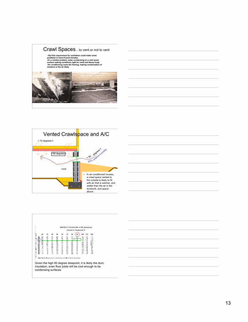
Crawl Spaces…to vent or not to vent• But this requirement for ventilation could make someproblems in warm-humid climates.•It’s a similar problem, water condensing on a cool woodsurface making conditions right for mold and decay fungi.•Air conditioning cools the framing, making condensation ofmoisture in the air likely
outsideinside
+ 90degrees f
.
80% relative humidity
+68 degrees f.
+ 72 degrees f.
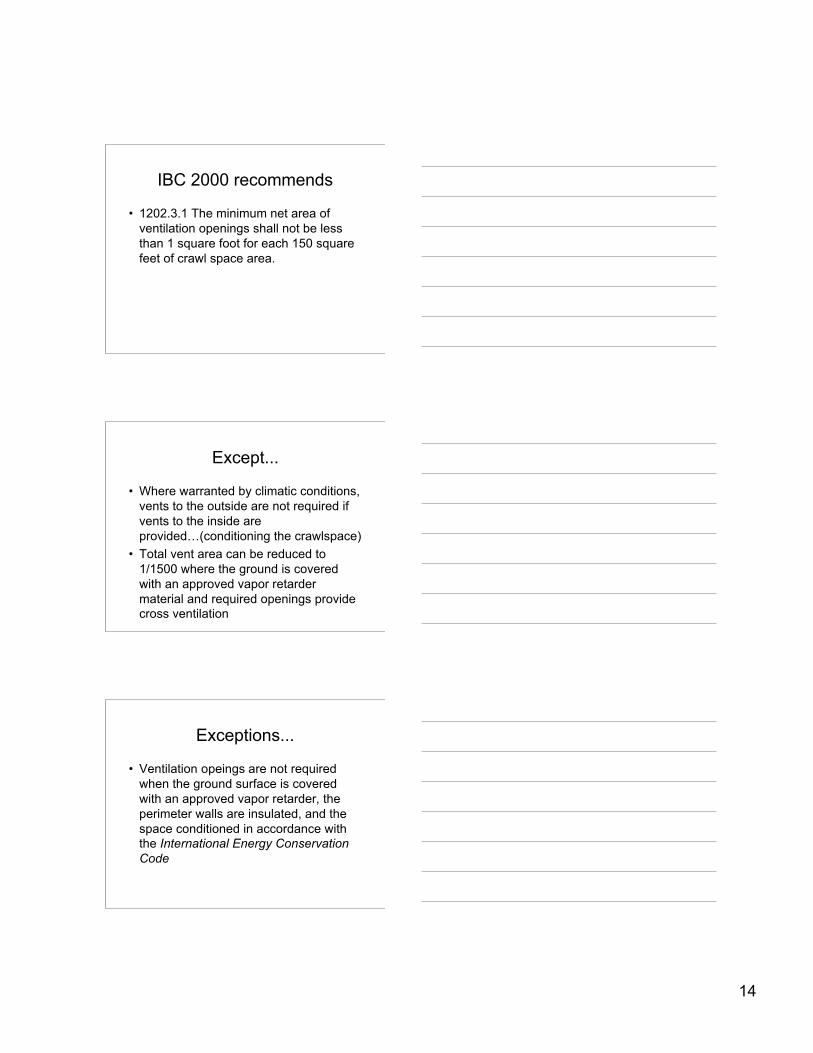
Vented Crawlspace and A/C
• In air conditioned houses,a crawl space vented tothe outside is likely to fillwith air that is warmer, andwetter than the air in theductwork, and spaceabove
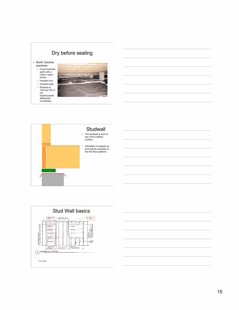
Given the high 82 degree dewpoint, it is likely the duct,insulation, even floor joists will be cool enough to becondensing surfaces
14
IBC 2000 recommends
• 1202.3.1 The minimum net area ofventilation openings shall not be lessthan 1 square foot for each 150 squarefeet of crawl space area.
Except...
• Where warranted by climatic conditions,vents to the outside are not required ifvents to the inside areprovided…(conditioning the crawlspace)
• Total vent area can be reduced to1/1500 where the ground is coveredwith an approved vapor retardermaterial and required openings providecross ventilation
Exceptions...
• Ventilation opeings are not requiredwhen the ground surface is coveredwith an approved vapor retarder, theperimeter walls are insulated, and thespace conditioned in accordance withthe International Energy ConservationCode
15
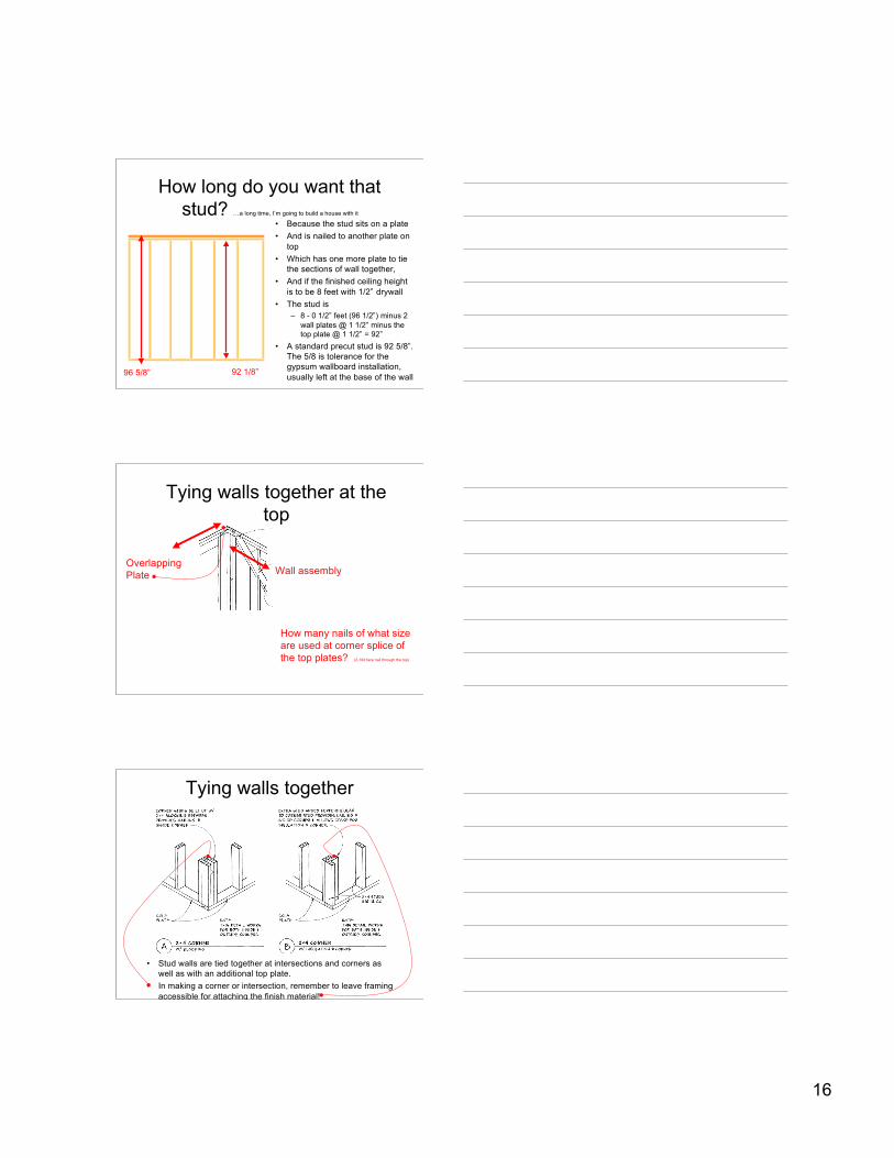
Dry before sealing
• North Carolinapractices:– Cover exposed
earth with aClass I vaporbarrier
– Insulate over– Insulate walls– Exhaust at
1cfm per 50 s.f.(oninside/outsidedifferentialhumidistat)
Studwall• The studwall is built on
top of the subfloorsurface.
• Ultimately it is tipped up.And stands vertically onthe first floor platform.
Stud Wall basics
From Thallon
16
How long do you want thatstud? …a long time, I’m going to build a house with it
• Because the stud sits on a plate• And is nailed to another plate on
top• Which has one more plate to tie
the sections of wall together,• And if the finished ceiling height
is to be 8 feet with 1/2” drywall• The stud is
– 8 - 0 1/2” feet (96 1/2”) minus 2wall plates @ 1 1/2” minus thetop plate @ 1 1/2” = 92”
• A standard precut stud is 92 5/8”.The 5/8 is tolerance for thegypsum wallboard installation,usually left at the base of the wall96 5/8” 92 1/8”
Tying walls together at thetop
Wall assemblyOverlapping Plate
How many nails of what sizeare used at corner splice ofthe top plates? (2-10d face nail through the top)
Tying walls together
• Stud walls are tied together at intersections and corners aswell as with an additional top plate.
• In making a corner or intersection, remember to leave framingaccessible for attaching the finish material!
17
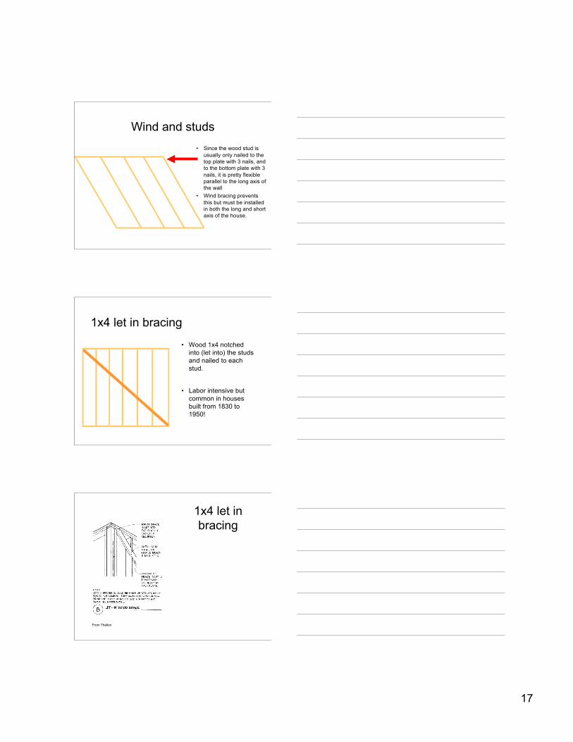
Wind and studs• Since the wood stud is
usually only nailed to thetop plate with 3 nails, andto the bottom plate with 3nails, it is pretty flexibleparallel to the long axis ofthe wall
• Wind bracing preventsthis but must be installedin both the long and shortaxis of the house.
1x4 let in bracing
• Wood 1x4 notchedinto (let into) the studsand nailed to eachstud.
• Labor intensive butcommon in housesbuilt from 1830 to1950!
1x4 let inbracing
From Thallon
18
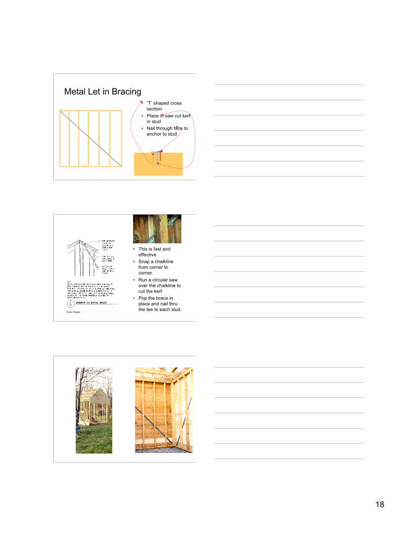
Metal Let in Bracing• ‘T’ shaped cross
section• Place in saw cut kerf
in stud• Nail through face to
anchor to stud
• This is fast andeffective.
• Snap a chalklinefrom corner tocorner.
• Run a circular sawover the chalkline tocut the kerf
• Pop the brace inplace and nail thruthe tee to each stud.
From Thallon
19
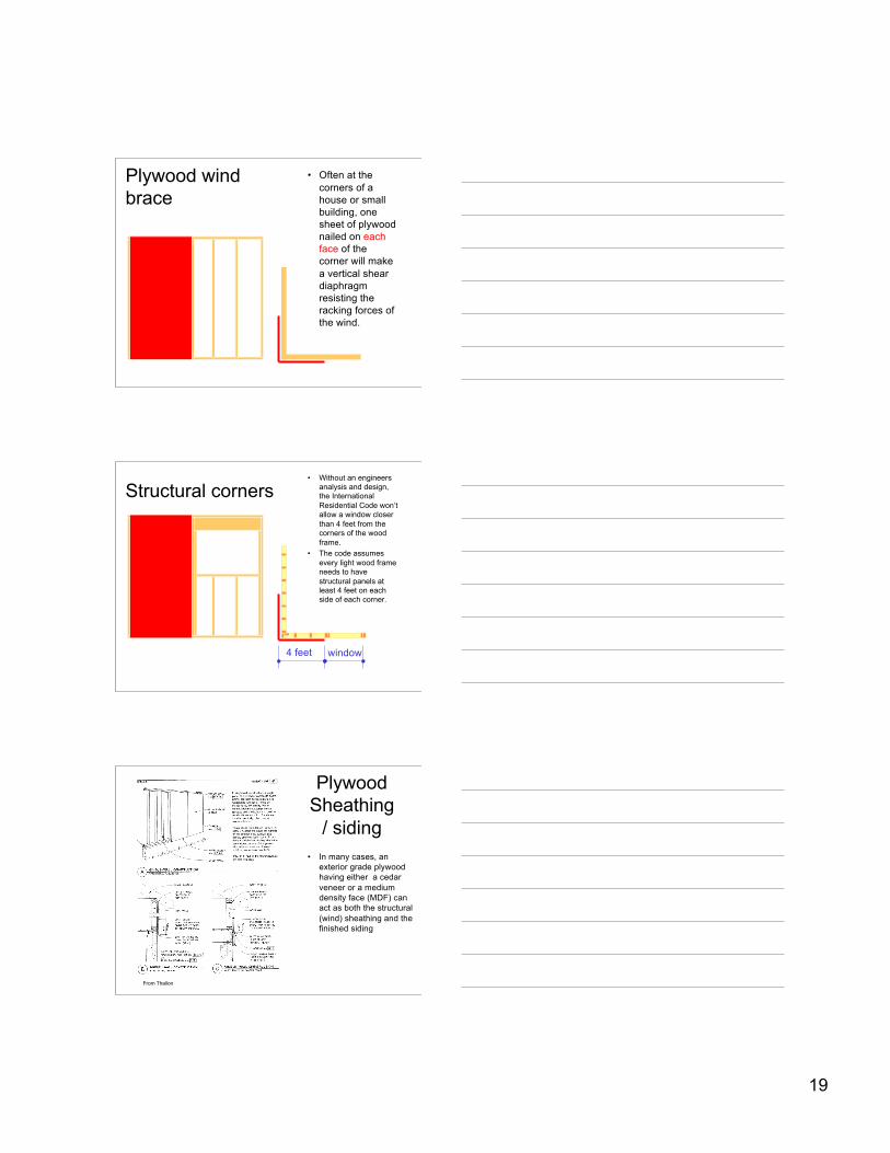
Plywood windbrace
• Often at thecorners of ahouse or smallbuilding, onesheet of plywoodnailed on eachface of thecorner will makea vertical sheardiaphragmresisting theracking forces ofthe wind.
Structural corners• Without an engineers
analysis and design,the InternationalResidential Code won’tallow a window closerthan 4 feet from thecorners of the woodframe.
• The code assumesevery light wood frameneeds to havestructural panels atleast 4 feet on eachside of each corner.
4 feet window
PlywoodSheathing
/ siding• In many cases, an
exterior grade plywoodhaving either a cedarveneer or a mediumdensity face (MDF) canact as both the structural(wind) sheathing and thefinished siding
From Thallon
20
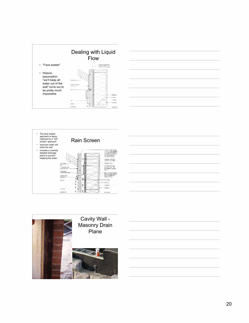
Dealing with LiquidFlow
• “Face sealed”
• Historicassumption:“we’ll keep allwater out of thewall” turns out tobe pretty muchimpossible.
Rain Screen• The face sealed
approach is beingreplaced by a “rainscreen” approach
• assumes water willenter the wall
• includes a carefullydetailed drainageplane to preventtrapping the water.
Cavity Wall -Masonry Drain
Plane
21
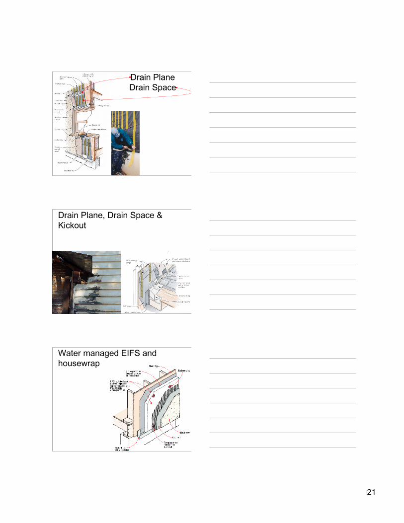
Drain PlaneDrain Space
Drain Plane, Drain Space &Kickout
Water managed EIFS andhousewrap
22
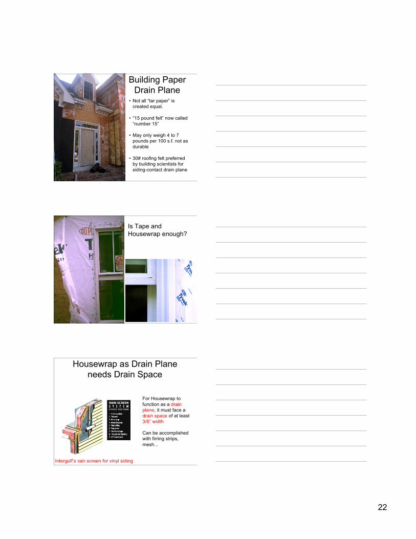
Building PaperDrain Plane
• Not all “tar paper” iscreated equal.
• “15 pound felt” now called“number 15”
• May only weigh 4 to 7pounds per 100 s.f. not asdurable
• 30# roofing felt preferredby building scientists forsiding-contact drain plane
Is Tape andHousewrap enough?
Intergulf’s rain screen for vinyl siding
For Housewrap tofunction as a drainplane, it must face adrain space of at least3/8” width
Can be accomplishedwith firring strips,mesh...
Housewrap as Drain Planeneeds Drain Space
23
24
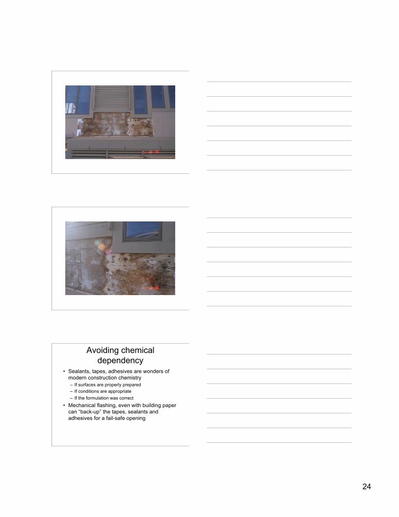
Avoiding chemicaldependency
• Sealants, tapes, adhesives are wonders ofmodern construction chemistry– If surfaces are properly prepared– If conditions are appropriate– If the formulation was correct
• Mechanical flashing, even with building papercan “back-up” the tapes, sealants andadhesives for a fail-safe opening
25
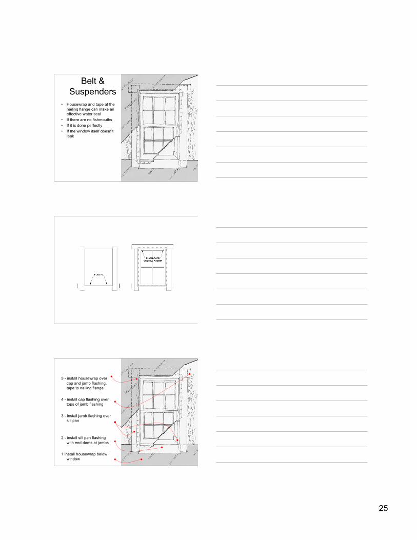
Belt &Suspenders
• Housewrap and tape at thenailing flange can make aneffective water seal
• If there are no fishmouths• If it is done perfectly• If the window itself doesn’t
leak
5 - install housewrap overcap and jamb flashing,tape to nailing flange
4 - install cap flashing overtops of jamb flashing
3 - install jamb flashing oversill pan
2 - install sill pan flashingwith end dams at jambs
1 install housewrap belowwindow
26
27
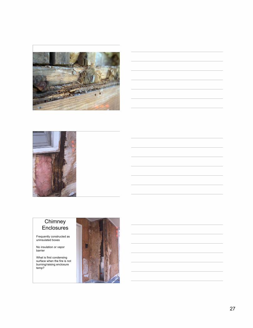
ChimneyEnclosures
Frequently constructed asuninsulated boxes
No insulation or vaporbarrier
What is first condensingsurface when the fire is notburning/raising enclosuretemp?
28
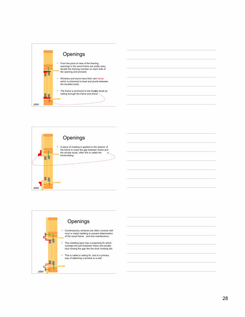
Openings• From the point of view of the framing,
openings in the wood frame are pretty easy,double the framing member on each side ofthe opening and proceed.
• Windows and doors have their own framewhich is shimmed to level and plumb betweenthe doubled studs
• The frame is anchored to the double studs bynailing through the frame and shims
plan
Openings• A piece of molding is applied to the exterior of
the frame to close the gap between frame andthe double studs, often this is called thebrickmolding
plan
Openings• Contemporary windows are often covered with
vinyl or metal cladding to prevent deteriorationof the wood frame…and end maintenance.
• This cladding layer has a projecting fin whichoverlaps the joint between frame and doublestud closing the gap like the brick molding did.
• This is called a nailing fin, and is a primaryway of attaching a window to a wall.
plan
29
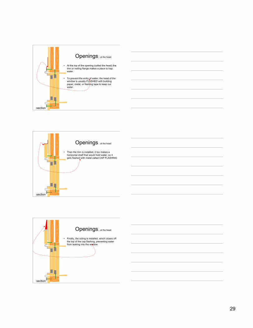
Openings…at the head
• At the top of the opening (called the head) thetrim or nailing flange makes a place to trapwater.
• To prevent the entry of water, the head of thewindow is usually FLASHED with buildingpaper, metal, or flashing tape to keep outwater.
section
Openings…at the head
• Then the trim is installed, it too makes ahorizontal shelf that would hold water, so itgets flashed with metal called CAP FLASHING
section
Openings…at the head
• Finally, the siding is installed, which closes offthe top of the cap flashing, preventing waterfrom leaking into the window.
section
30
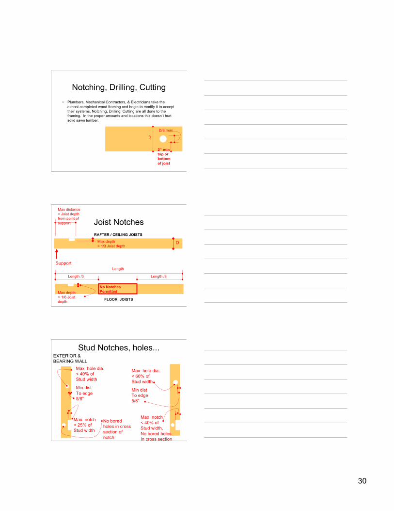
Notching, Drilling, Cutting• Plumbers, Mechanical Contractors, & Electricians take the
almost completed wood framing and begin to modify it to accepttheir systems. Notching, Drilling, Cutting are all done to theframing. In the proper amounts and locations this doesn’t hurtsolid sawn lumber.
D/3 max
D
2” mintop orbottomof joist
Joist Notches
D
Support
Max distance= Joist depthfrom point ofsupport
Max depth= 1/3 Joist depth
Length
Length /3Length /3
No NotchesPermittedMax depth
= 1/6 Joistdepth
RAFTER / CEILING JOISTS
FLOOR JOISTS
Stud Notches, holes...
Max notch< 25% ofStud width
Max hole dia.< 40% ofStud width
Min distTo edge5/8”
EXTERIOR & BEARING WALL
No boredholes in crosssection ofnotch
Max hole dia.< 60% ofStud width
Min distTo edge5/8”
Max notch< 40% ofStud width, No bored holesIn cross section