Embed Size (px)
Citation preview
1
Light Dependent Resistor Circuit by VK4ION Building a Simple Light Dependent circuit using 7 components
Image 1 - Original circuit with amendments
Amendments allow LED to light with changes to light conditions; total darkness is not required
This circuit detects darkness and allows the LED to turn on See Image 1 – and note hand written amendments
The original project called for the LDR [Light Dependent Resistor] to function in total darkness. i.e. When it sensed DARK it would ‘turn on’ the LED.
This posed several problems for me so I amended the circuit and marked my changes on the circuit diagram.
In my circuit the LDR is Off when in ambient light. It turns-ON when it senses a change of light. E.g. passing your hand over the LDR lights the LED.
As a beginner project this gives more satisfaction to the student as they immediately see the results & don’t have to wait until dark [and hand waving is such fun].
To achieve this change 2 things were done.
1. Changed the SIZE of the Resistor used between the +ive power rail
and the LDR. Substituted 6.8k for the original 100k resistor
2. Fitted a resistor to protect the LED [between the LED & T1]
7 Components required:
2 x Transistors 2N2222A [also labelled T092 or PN2222A]
LED – Blue is more tolerant to current/voltage fluctuations so is more forgiving while playing around and getting the circuit just right
LDR – Light Dependent Resistor
Resistor 1: anywhere between 6.8k to 10k - joins +ive supply rail to LDR
Resistor 2: 1k - joins +ive supply rail and T2 [Transistor 2]
Resistor 3: 180 to 330 - between LED & T1 [Transistor 1]
Note: This project requires 3Volts so use 2 x AA batteries
If using the ‘breadboard power supply’ See note 1 for tips and warnings.
2
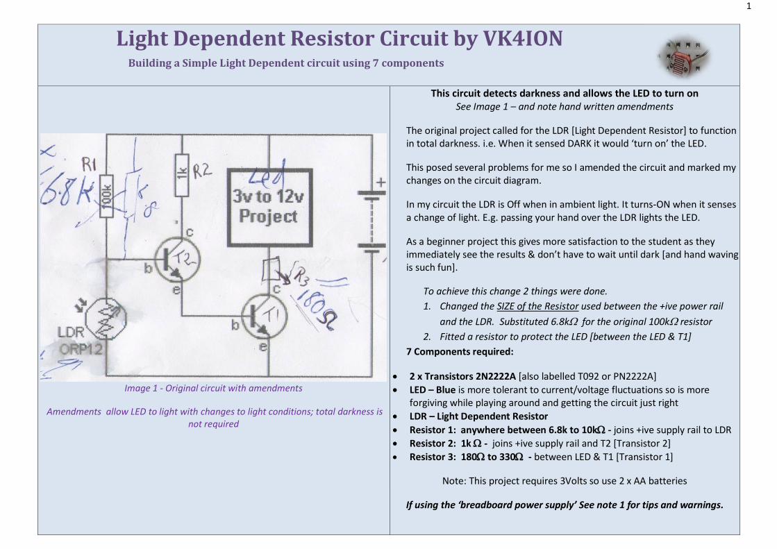
Image 2 working circuit on breadboard
See Images 2 for component layout – showing circuit in the same plane as the schematic. LDR to the Left, LED to the Right
Step 1: Check the schematic – Insert 3 components that have a ‘leg’ the +ive rail
LED has it’s +ive leg [longer leg] in the +ive rail
R2 - 1k resistor, to the T2 has a leg in the +ive rail
R1 - 6.8k resistor, to the LDR has a leg in the +ive rail
Step 2: Insert LDR, T2 & R3,
Insert LDR into cross-row to join R1 – note space to put a jumper later
Insert T2 – Collector leg in row to join the Resistor R1
Insert R3 - Resistor to protect the LED - one leg in same cross-row as LED other leg goes to new cross-row
Step 3: Insert T1
Insert T1 – Collector leg in row to join the Resistor R3
Base & Emitter to unused cross-rows All 7 components are now in the circuit – time to add jumper leads to connect the circuit
3
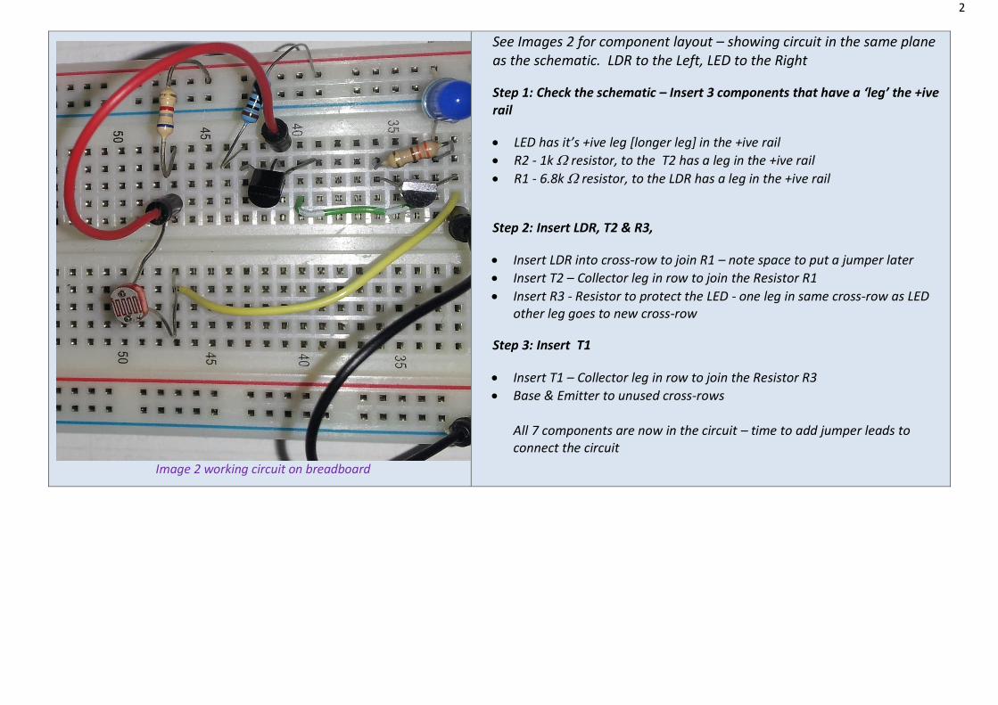
Image 3
Step 4:Insert jumper leads to connect the components See image 3 coloured Jumpers – J1 Yellow; J2 Green/white; J3 Red; J4 Black J1 – yellow - joins LDR to the EMITTER of T1 in series J2 – green/white - joins EMITTER of T2 to BASE of T1 J3 – red – one leg goes in space between the LDR & it’s Resistor R1 Other leg goes to BASE of T2 Finally the circuit must go to the NEGATIVE rail Insert J4 – black One leg in –ive rail – other end to cross-row T1 EMITTER [that cross-row has 3 pins when complete]
Check the circuit – is there an unbroken ‘loop’ of power around the board?
Components have both ends connected – to another component or jumper? Time to put the 3volts of power into the breadboard The LED may flash at first but it should NOT remain lit. Pass your hand over the Light Dependent Resistor and the LED will glow As daylight disappears the LED begins to glow more brightly.
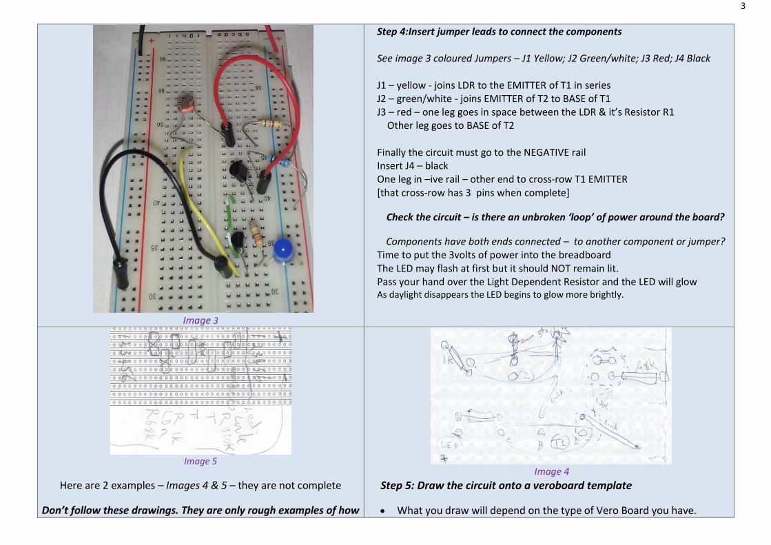
Image 5
Here are 2 examples – Images 4 & 5 – they are not complete
Don’t follow these drawings. They are only rough examples of how
Image 4
Step 5: Draw the circuit onto a veroboard template
What you draw will depend on the type of Vero Board you have.
4
to begin working with veroboard Draw on paper what you are going to build
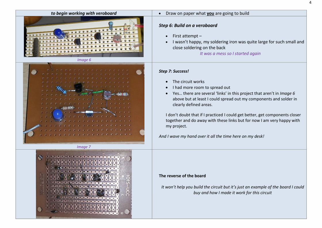
Image 6
Step 6: Build on a veroboard
First attempt –
I wasn’t happy, my soldering iron was quite large for such small and close soldering on the back
It was a mess so I started again
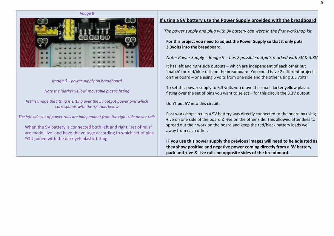
Image 7
Step 7: Success!
The circuit works
I had more room to spread out
Yes… there are several ‘links’ in this project that aren’t in Image 6 above but at least I could spread out my components and solder in clearly defined areas.
I don’t doubt that if I practiced I could get better, get components closer together and do away with these links but for now I am very happy with my project.
And I wave my hand over it all the time here on my desk!
The reverse of the board
It won’t help you build the circuit but it’s just an example of the board I could buy and how I made it work for this circuit
5
Image 8
Image 9 – power supply on breadboard
Note the ‘darker yellow’ moveable plastic fitting
In this image the fitting is sitting over the 5v output power pins which corresponds with the +/- rails below
The left side set of power rails are independent from the right side power rails
When the 9V battery is connected both left and right “set of rails” are made ‘live’ and have the voltage according to which set of pins YOU joined with the dark yell plastic fitting
If using a 9V battery use the Power Supply provided with the breadboard
The power supply and plug with 9v battery cap were in the first workshop kit
For this project you need to adjust the Power Supply so that it only puts 3.3volts into the breadboard.
Note: Power Supply - Image 9 - has 2 possible outputs marked with 5V & 3.3V
It has left and right side outputs – which are independent of each other but ‘match’ for red/blue rails on the breadboard. You could have 2 different projects on the board – one using 5 volts from one side and the other using 3.3 volts.
To set this power supply to 3.3 volts you move the small darker yellow plastic fitting over the set of pins you want to select – for this circuit the 3.3V output
Don’t put 5V into this circuit.
Past workshop circuits a 9V battery was directly connected to the board by using +ive on one side of the board & -ive on the other side. This allowed attendees to spread out their work on the board and keep the red/black battery leads well away from each other.
IF you use this power supply the previous images will need to be adjusted as they show positive and negative power coming directly from a 3V battery pack and +ive & -ive rails on opposite sides of the breadboard.


![Light Dependent Resistor Circuit by VK4IONvk4ion.com.au/docs/LDR_Circuit.pdf · The original project called for the LDR [Light Dependent Resistor] to function in total darkness. i.e](https://img.pdfslide.us/doc/110x75/60700f2c41a28222a73a0e16/light-dependent-resistor-circuit-by-the-original-project-called-for-the-ldr-light.jpg)