Embed Size (px)
Citation preview

Electricity
©Catlin.Fatu@English Language Wikipedia
National 5 PhysicsKnox Academy

Throughout the Course, appropriate attention should be given to units, prefixes and scientific notation.
tera T 1012 x 1,000,000,000,000giga G 109 x 1,000,000,000mega M 106 x 1,000,000kilo k 103 x 1,000centi c 10-2 /100milli m 10-3 /1,000micro µ 10-6 /1,000,000nano n 10-9 /1,000,000,000pico p 10-12 /1,000,000,000,000
In this section the prefixes you will use most often are milli (m), micro (µ), kilo (k), and mega (M) and giga (G). It is essential that you use these correctly in calculations.
In Physics, the standard unit for time is the second (s) and therefore if time is given in milliseconds (ms) or microseconds (µs) it must be converted to seconds.
Example 1An electronic system is now used and is able to perform the same experiment in 0.5 ms. How long is this?
0.5 ms = 0.5 milliseconds = 0.5 x 10⁻³ s = 0.5/1 000 = 0.0005 seconds. In this unit we use the unit amperes, which is the unit of current. Often there will be currents which are measured in mA and µA.
Example 2An ammeter reading shows that there are 54.2 µA of current in a circuit? How many amperes is this?
54.2 µA = 54.2 microamperes = 54.2 x 10⁻⁶ A = 54.2/1 000 000 = 0.0000542 amperes.
In this unit we use the unit for power – the Watt, W, this may be measured in kW and MW.
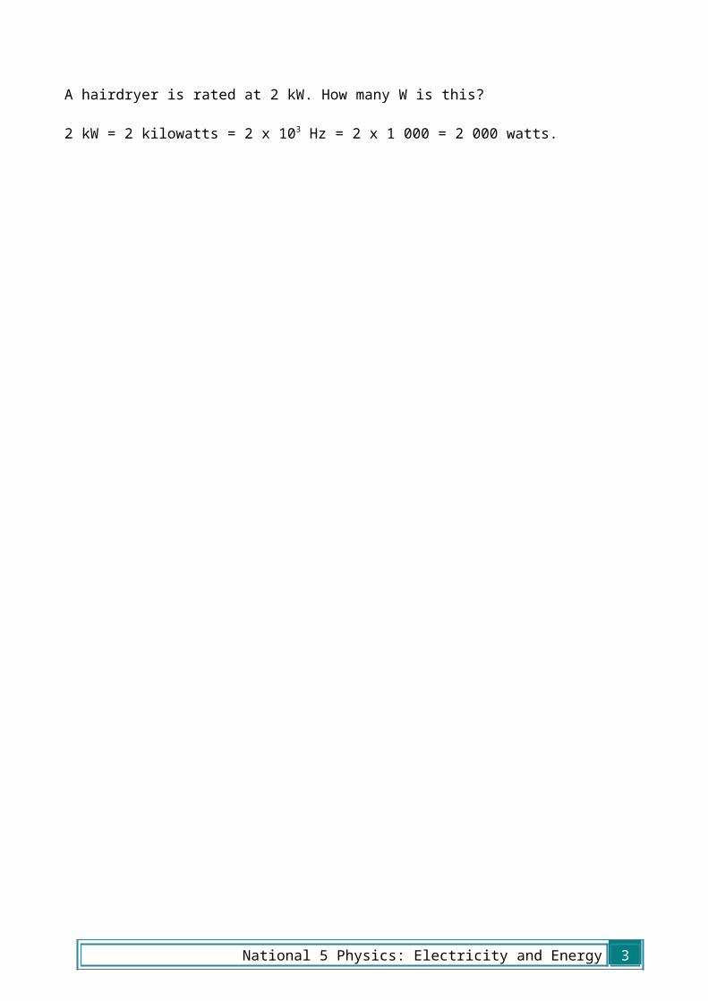
Example 3A hairdryer is rated at 2 kW. How many W is this?
2 kW = 2 kilowatts = 2 x 10³ Hz = 2 x 1 000 = 2 000 watts.
2 National 5 Physics: Electricity and Energy
Learning Outcomes:1. Electric Charge
1.1. Definition of electric charge in terms of positive and negative. 1.2. Effect of electric field on a charge. 1.3. Electrical current as the electrical charge transferred per unit time. 1.4. Use appropriate relationship to carry out calculations involving
charge, current and time.
Q=¿
2. Potential Difference2.1. The potential difference (voltage) of the supply is a measure of the
energy given to the charge carrier in a circuit.2.2. Difference between alternating and direct current.
3. Practical electrical and electronic circuits3.1. Use of an appropriate relationship to calculate the resistance of
resistors in series and in parallel circuits. 3.2. Measurement of current, voltage and resistance, using appropriate
meters in complex circuits. 3.3. The function and application of standard electrical and electronic
components including cell, battery, lamp, switch, resistor, variable resistor, voltmeter, ammeter, LED, motor, loudspeaker, photovoltaic cell, fuse, diode, capacitor, thermistor, LDR.
3.4. Current and voltage relationships in a series circuit. 3.5. Current and voltage relationships in a parallel circuit.
Rtotal=R1+R2+R3+…
1R total
= 1R1
+ 1R2
+ 1R3
+…
I 1=I2=I3=I 4…
V S=V 1+V 2+V 3…
IP=I 1+ I 2+ I 3…
V P=V 1=V 2=V 3…
National 5 Physics: Electricity and Energy 3
4. Ohm’s law4.1. Use of a V-I graph to determine resistance.4.2. Use of an appropriate relationship to calculate potential difference
(voltage), current and resistance. 4.3. The relationship between temperature and resistance of a
conductor.
V=IR
5. Electrical Power5.1. Use of an energy, power and time relationship. 5.2. Use of an appropriate relationship to determine the power, voltage,
current and resistance in electrical circuits.
P= Et
P=IV
P=I 2R
P=V2
R
4 National 5 Physics: Electricity and Energy

1. Charge and Current
Charge
Charge is the name we give to one of the properties of a material. Charge can either be positive or negative. Positive charge will attract negative charge and vice versa, but negative charge will repel other negative charge: the same will happen with two positive charges.
Opposite charges attract
Like charges repel
You can investigate these effects by rubbing a balloon against your jumper – it will become charged and you will be able to stick it on a wall!
The symbol we use for charge is Q and the unit of charge is the coulomb which we write as C.
Surrounding all charged particles there is an electric field. In physics, when we talk about fields, we mean a place where an object will experience a force.
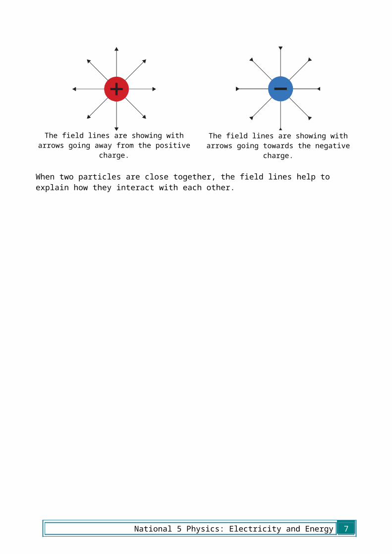
We represent fields as a series of lines. This is shown below for positive and negative charges below.
The lines have arrows showing the direction that a positive charge to move in as a result of the field. In this case a positive charge would move away from the positive charge as like charges repel. In the case of the negative charge, a positive charge would be attracted, so the arrows point towards it.
The field lines are showing with arrows going away from the positive charge.
The field lines are showing with arrows going towards the negative charge.
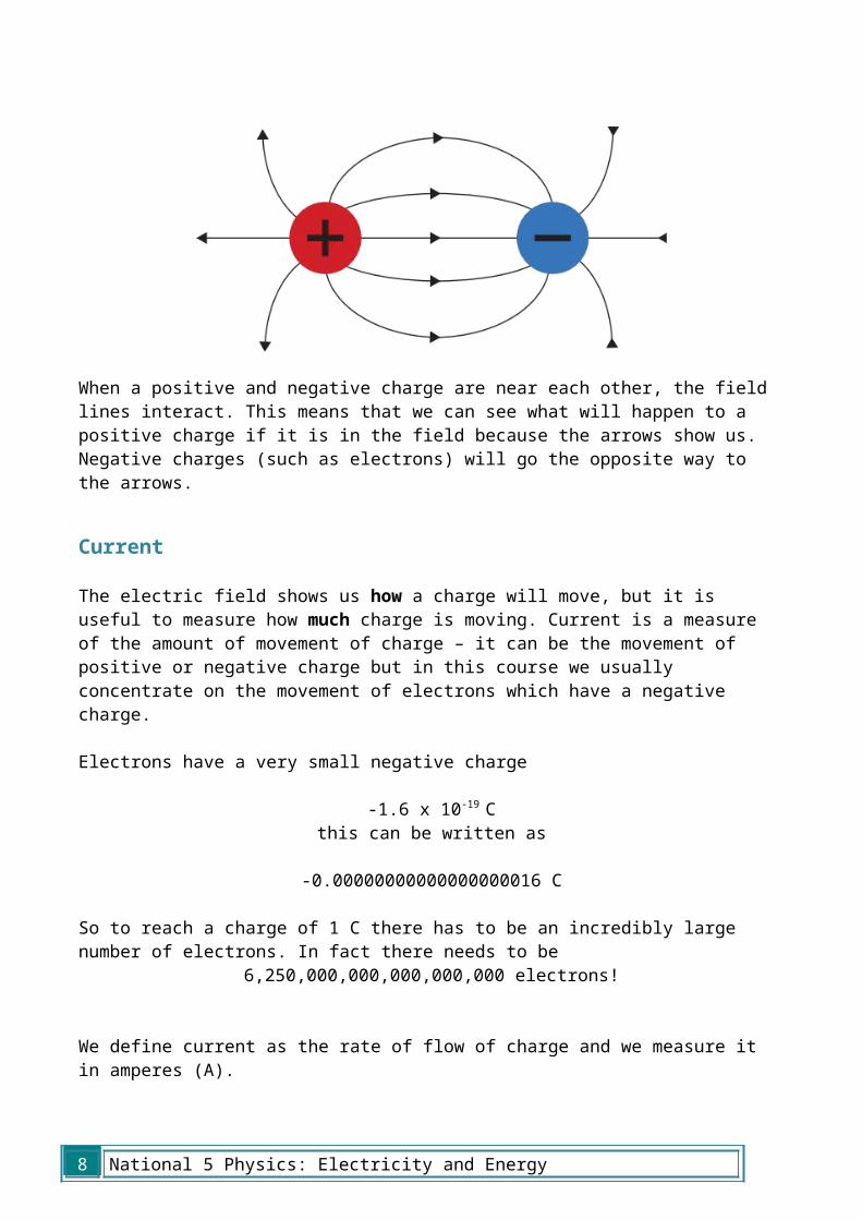
When two particles are close together, the field lines help to explain how they interact with each other.
National 5 Physics: Electricity and Energy 5

When a positive and negative charge are near each other, the field lines interact. This means that we can see what will happen to a positive charge if it is in the field because the arrows show us. Negative charges (such as electrons) will go the opposite way to the arrows.
Current
The electric field shows us how a charge will move, but it is useful to measure how much charge is moving. Current is a measure of the amount of movement of charge – it can be the movement of positive or negative charge but in this course we usually concentrate on the movement of electrons which have a negative charge.
Electrons have a very small negative charge
-1.6 x 10⁻¹⁹ Cthis can be written as
-0.00000000000000000016 C
So to reach a charge of 1 C there has to be an incredibly large number of electrons. In fact there needs to be
6,250,000,000,000,000,000 electrons!
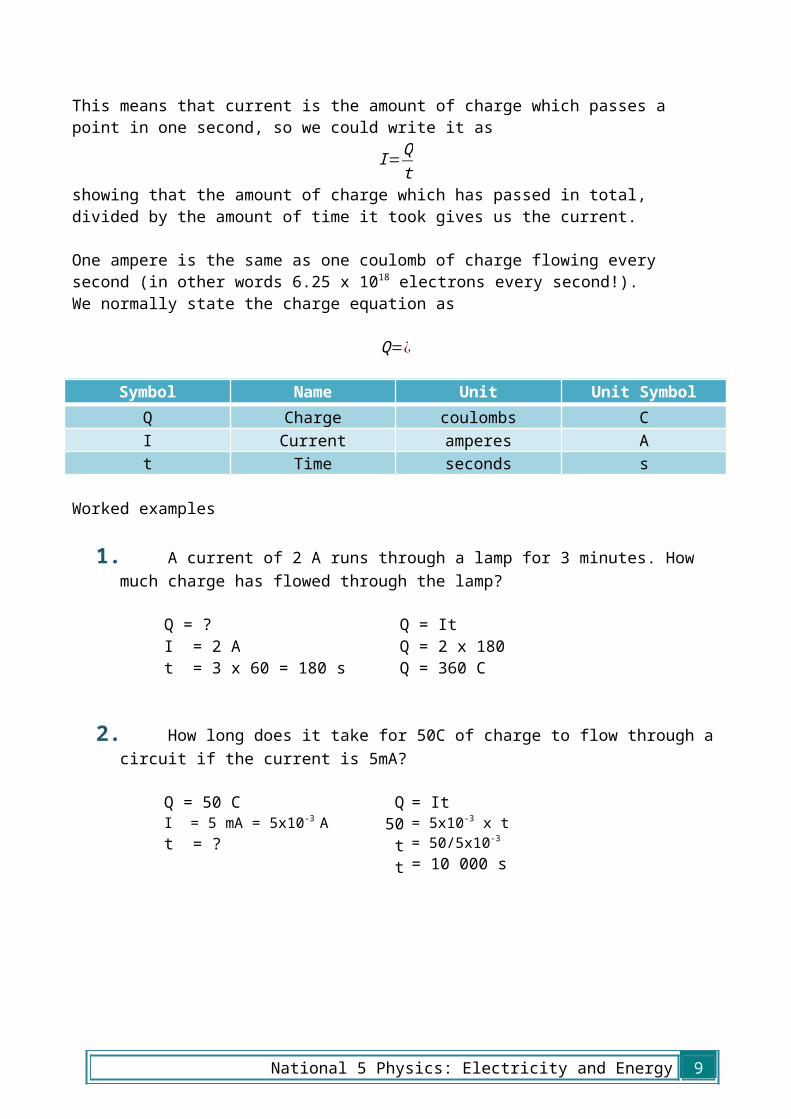
We define current as the rate of flow of charge and we measure it in amperes (A).This means that current is the amount of charge which passes a point in one second, so we could write it as
I=Qt
showing that the amount of charge which has passed in total, divided by the amount of time it took gives us the current.
6 National 5 Physics: Electricity and Energy
One ampere is the same as one coulomb of charge flowing every second (in other words 6.25 x 10¹⁸ electrons every second!).We normally state the charge equation as
Q=¿
Symbol Name Unit Unit SymbolQ Charge coulombs CI Current amperes At Time seconds s
Worked examples
1. A current of 2 A runs through a lamp for 3 minutes. How much charge has flowed through the lamp?
Q = ?I = 2 At = 3 x 60 = 180 s
Q = ItQ = 2 x 180Q = 360 C
2. How long does it take for 50C of charge to flow through a circuit if the current is 5mA?
Q = 50 CI = 5 mA = 5x10⁻³ At = ?
Q50
tt
= It= 5x10⁻³ x t= 50/5x10-3
= 10 000 s
National 5 Physics: Electricity and Energy 7
Conductors and Insulators
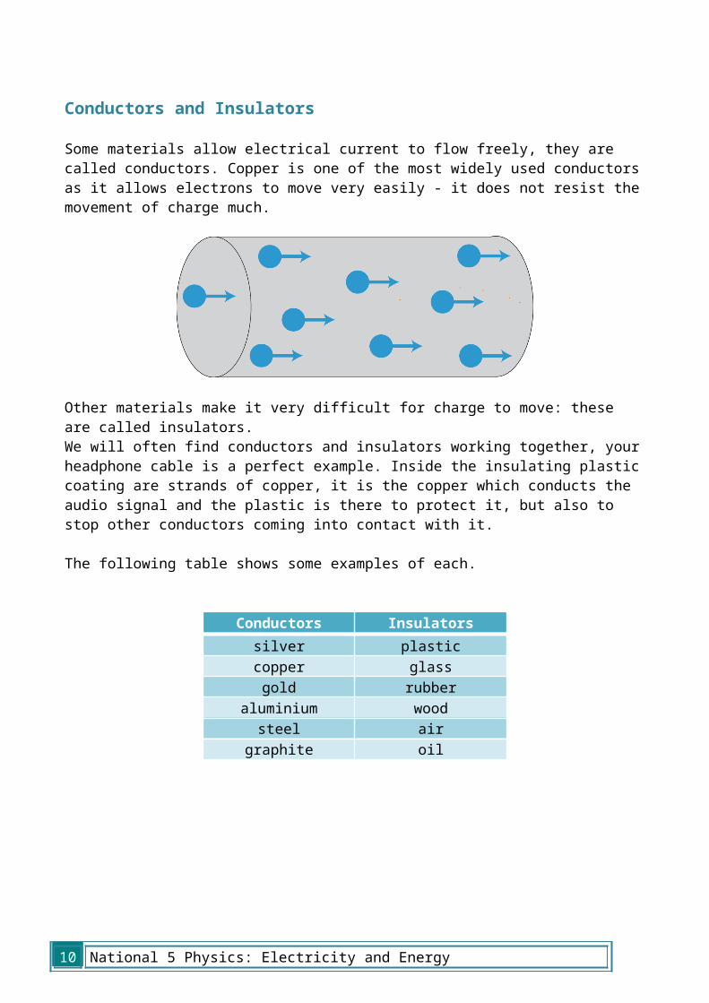
Some materials allow electrical current to flow freely, they are called conductors. Copper is one of the most widely used conductors as it allows electrons to move very easily - it does not resist the movement of charge much.
Other materials make it very difficult for charge to move: these are called insulators. We will often find conductors and insulators working together, your headphone cable is a perfect example. Inside the insulating plastic coating are strands of copper, it is the copper which conducts the audio signal and the plastic is there to protect it, but also to stop other conductors coming into contact with it.
The following table shows some examples of each.
ΩConductors Insulators
silver plasticcopper glass
gold rubberaluminium wood
steel airgraphite oil
8 National 5 Physics: Electricity and Energy
2. Potential DifferenceThe purpose of circuits is to transform electrical potential energy into a more useful form. For current to flow in a circuit, charges in that circuit must be moving. For them to move, they need to be given energy. As current flows round a circuit, each coulomb of charge gains energy in the supply and this is transformed in the components of the circuit.
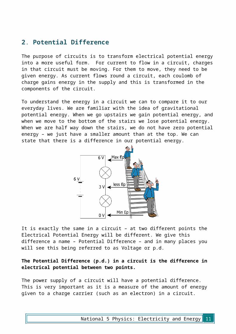
To understand the energy in a circuit we can to compare it to our everyday lives. We are familiar with the idea of gravitational potential energy. When we go upstairs we gain potential energy, and when we move to the bottom of the stairs we lose potential energy. When we are half way down the stairs, we do not have zero potential energy – we just have a smaller amount than at the top. We can state that there is a difference in our potential energy.
It is exactly the same in a circuit – at two different points the Electrical Potential Energy will be different. We give this difference a name – Potential Difference – and in many places you will see this being referred to as Voltage or p.d.
The Potential Difference (p.d.) in a circuit is the difference in electrical potential between two points.
The power supply of a circuit will have a potential difference. This is very important as it is a measure of the amount of energy given to a charge carrier (such as an electron) in a circuit.
Potential difference is measured in volts (V). 1 volt is equal to 1 joule for every coulomb of charge which passes. 1 V = 1 J/C. For example, a 5 V supply will supply 5 joules of energy to every coulomb which passes through.
One side of the power supply will have a larger electrical potential than the other – this will be the positive side, and the other will be the negative side.
National 5 Physics: Electricity and Energy 9
Charge carriers will follow the rules for electric fields, for example electrons will flow from the negative terminal to the positive terminal.
AC and DC
There are two types of current in circuits - Alternating Current (AC) and Direct Current (DC).
In DC circuits, the charge carriers will only flow one direction round a circuit, in the case of electrons, this is from the negative to the positive terminal.
In AC circuits, the terminals constantly change (in the UK the frequency mains circuits is 50 Hz, so the current changes direction 100 times a second) between positive and negative, so the charges constantly change direction. The energy transfer in these circuits still happens because the movement of the charges changes the electric field around them.
We can investigate the waveforms of electrical signals using an oscilloscope. An
oscilloscope shows time on the x-axis and amplitude of the signal on the y-axis. Each square on an oscilloscope is called a ‘division.’ There are dials on oscilloscopes which allow us to change the value of each division, both for time and for p.d. Two examples are shown below.
10 National 5 Physics: Electricity and Energy
This is an AC trace from an oscilloscope, the x axis is time and the y axis is potential difference. The p.d. is changing between positive and negative values. If the timebase is set to 1 ms/division and the y-gain is set to 2 V/division then the peak value of this signal is 8 V and the frequency is 200 Hz.
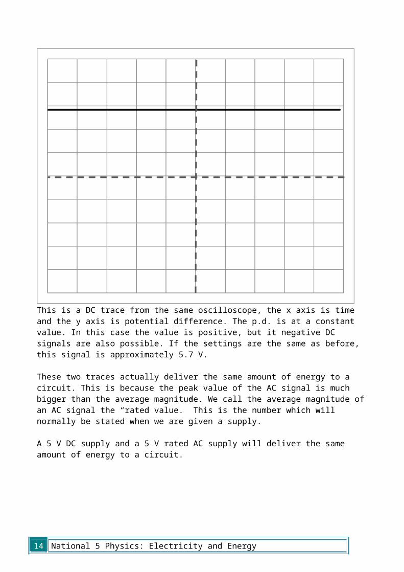
This is a DC trace from the same oscilloscope, the x axis is time and the y axis is potential difference. The p.d. is at a constant value. In this case the value is positive, but it negative DC signals are also possible. If the settings are the same as before, this signal is approximately 5.7 V.
These two traces actually deliver the same amount of energy to a circuit. This is because the peak value of the AC signal is much bigger than the average magnitude. We call the average magnitude of an AC signal the “rated value.” This is the number which will normally be stated when we are given a supply.
A 5 V DC supply and a 5 V rated AC supply will deliver the same amount of energy to a circuit.
National 5 Physics: Electricity and Energy 11
3. Practical Circuits
Resistance
Resistance is a measure of how much opposition there is to the current in a circuit. The more resistance there is, the harder it is for current to flow. All components in circuits, such as lamps, loudspeakers and motors have a resistance – even the connecting wires do. The energy transformation in a resistor is from electrical to heat.
The symbol for resistance is R and it is measured in ohms, there is a special symbol for ohms, Ω. For example a resistor may have a resistance of 100 Ω.
In order to draw a circuit, it is convenient to use symbols which identify different components.
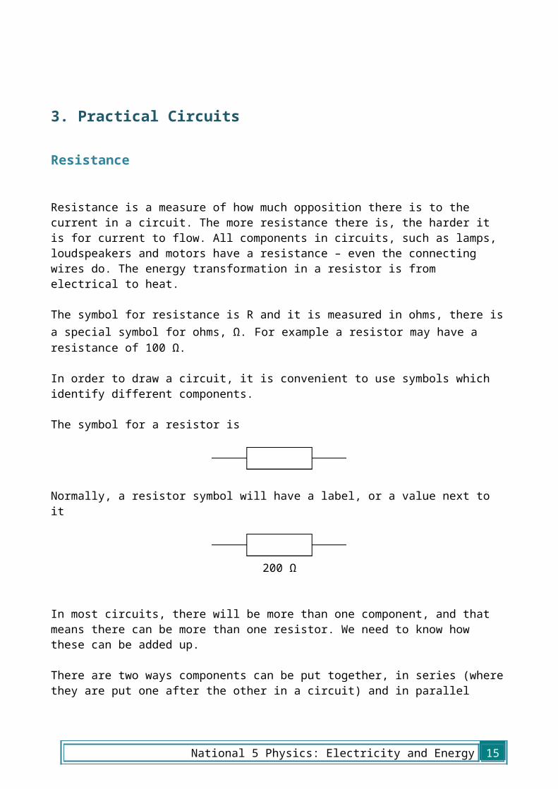
The symbol for a resistor is
Normally, a resistor symbol will have a label, or a value next to it
200 Ω
In most circuits, there will be more than one component, and that means there can be more than one resistor. We need to know how these can be added up.
There are two ways components can be put together, in series (where they are put one after the other in a circuit) and in parallel (where they are placed side by side). Over the next few pages you will find out various rules associated with these circuits.
12 National 5 Physics: Electricity and Energy

Resistors in series
The resistors here are shown in series. If you imagine that each resistor is a tunnel and lots of people want to get from the left to the right, each tunnel is going to slow them down. In other words, the delay at each resistor will add up.
In equation form, this is
Rtotal=R1+R2+R3+…
Symbol Name Unit Unit SymbolRtotal Total Resistance ohms ΩR1 Resistance 1 ohms ΩR2 Resistance 2 ohms Ω
R3etc Other resistors ohms ΩIn this equation we put … at the end as there can be any number of resistances.
Worked examples
1. Calculate the resistance of the following circuit
RtotalR1R2R3
= ?= 60 Ω= 35 Ω= 22 Ω
RtotalRtotalRtotal
= R1 + R2 + R3= 60 + 35 + 22= 117 Ω
2. The total resistance of this circuit is 25 kΩ. Calculate the value of Resistor 2
RtotalR1R2R3
= 25 kΩ= 12 kΩ= ?= 500 Ω
Rtotal25000
R2R2R2
= R1 + R2 + R3= 12000 + R2 + 500= 25000 – 12500= 12500= 12.5 kΩ
R1 R2 R3
60 Ω 35 Ω 22 Ω
12 kΩ
R2 500 Ω
National 5 Physics: Electricity and Energy 13
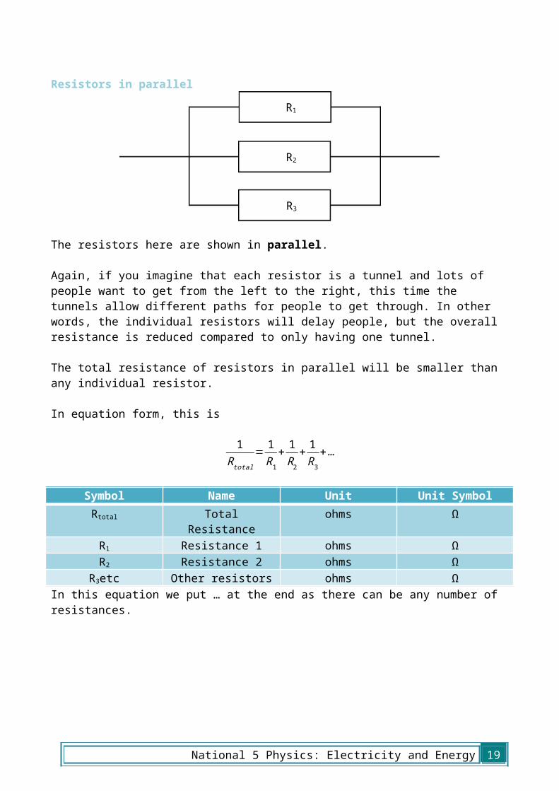
Resistors in parallel
The resistors here are shown in parallel. Again, if you imagine that each resistor is a tunnel and lots of people want to get from the left to the right, this time the tunnels allow different paths for people to get through. In other words, the individual resistors will delay people, but the overall resistance is reduced compared to only having one tunnel.
The total resistance of resistors in parallel will be smaller than any individual resistor.
In equation form, this is
1R total
= 1R1
+ 1R2
+ 1R3
+…
Symbol Name Unit Unit SymbolRtotal Total Resistance ohms ΩR1 Resistance 1 ohms ΩR2 Resistance 2 ohms Ω
R3etc Other resistors ohms ΩIn this equation we put … at the end as there can be any number of resistances.
R1
R2
R3
14 National 5 Physics: Electricity and Energy
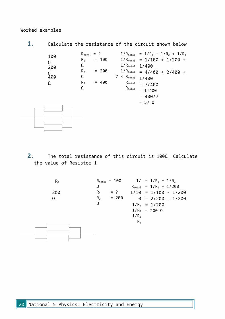
Worked examples
1. Calculate the resistance of the circuit shown below
2. The total resistance of this circuit is 100Ω. Calculate the value of Resistor 1
100 Ω
200 Ω
400 Ω
200 Ω
R1
National 5 Physics: Electricity and Energy 15
Rtotal = ?R1 = 100 ΩR2 = 200 ΩR3 = 400 Ω
1/Rtotal1/Rtotal1/Rtotal1/Rtotal
7 × RtotalRtotalRtotal
= 1/R1 + 1/R2 + 1/R3= 1/100 + 1/200 + 1/400= 4/400 + 2/400 + 1/400= 7/400= 1×400= 400/7= 57 Ω
Rtotal = 100 ΩR1 = ?R2 = 200 Ω
1/Rtotal1/10
01/R11/R11/R1
R1
= 1/R1 + 1/R2= 1/R1 + 1/200= 1/100 - 1/200= 2/200 - 1/200= 1/200= 200 Ω
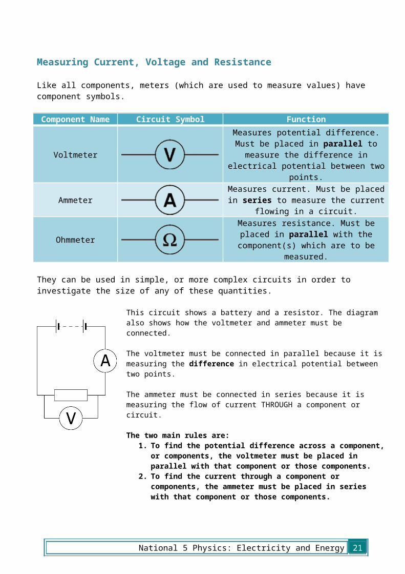
Measuring Current, Voltage and Resistance
Like all components, meters (which are used to measure values) have component symbols.
Component Name Circuit Symbol Function
VoltmeterMeasures potential difference. Must
be placed in parallel to measure the difference in electrical potential
between two points.
AmmeterMeasures current. Must be placed in
series to measure the current flowing in a circuit.
OhmmeterMeasures resistance. Must be placed
in parallel with the component(s) which are to be measured.
They can be used in simple, or more complex circuits in order to investigate the size of any of these quantities.
This circuit shows a battery and a resistor. The diagram also shows how the voltmeter and ammeter must be connected.
The voltmeter must be connected in parallel because it is measuring the difference in electrical potential between two points.
The ammeter must be connected in series because it is measuring the flow of current THROUGH a component or circuit.
The two main rules are:1. To find the potential difference across a component, or
components, the voltmeter must be placed in parallel with that component or those components.
2. To find the current through a component or components, the ammeter must be placed in series with that component or those components.
The previous diagram does not show an ohmmeter because, in most cases, resistance should only be measured when a circuit is not ‘on’ or fully connected.
To use an ohmmeter, you would place it ‘across’ a component – in parallel, just like a voltmeter.
16 National 5 Physics: Electricity and Energy

National 5 Physics: Electricity and Energy 17

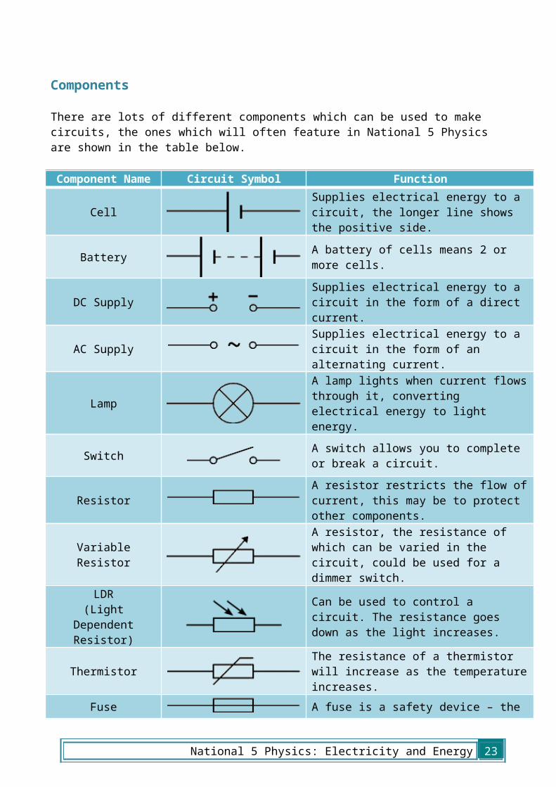
Components
There are lots of different components which can be used to make circuits, the ones which will often feature in National 5 Physics are shown in the table below.
Component Name Circuit Symbol Function
CellSupplies electrical energy to a circuit, the longer line shows the positive side.
Battery A battery of cells means 2 or more cells.
DC Supply Supplies electrical energy to a circuit in the form of a direct current.
AC Supply Supplies electrical energy to a circuit in the form of an alternating current.
LampA lamp lights when current flows through it, converting electrical energy to light energy.
Switch A switch allows you to complete or break a circuit.
ResistorA resistor restricts the flow of current, this may be to protect other components.
Variable ResistorA resistor, the resistance of which can be varied in the circuit, could be used for a dimmer switch.
LDR(Light Dependent
Resistor)
Can be used to control a circuit. The resistance goes down as the light increases.
ThermistorThe resistance of a thermistor will increase as the temperature increases.
FuseA fuse is a safety device – the metal core will melt when too much current is flowing in the circuit.
18 National 5 Physics: Electricity and Energy
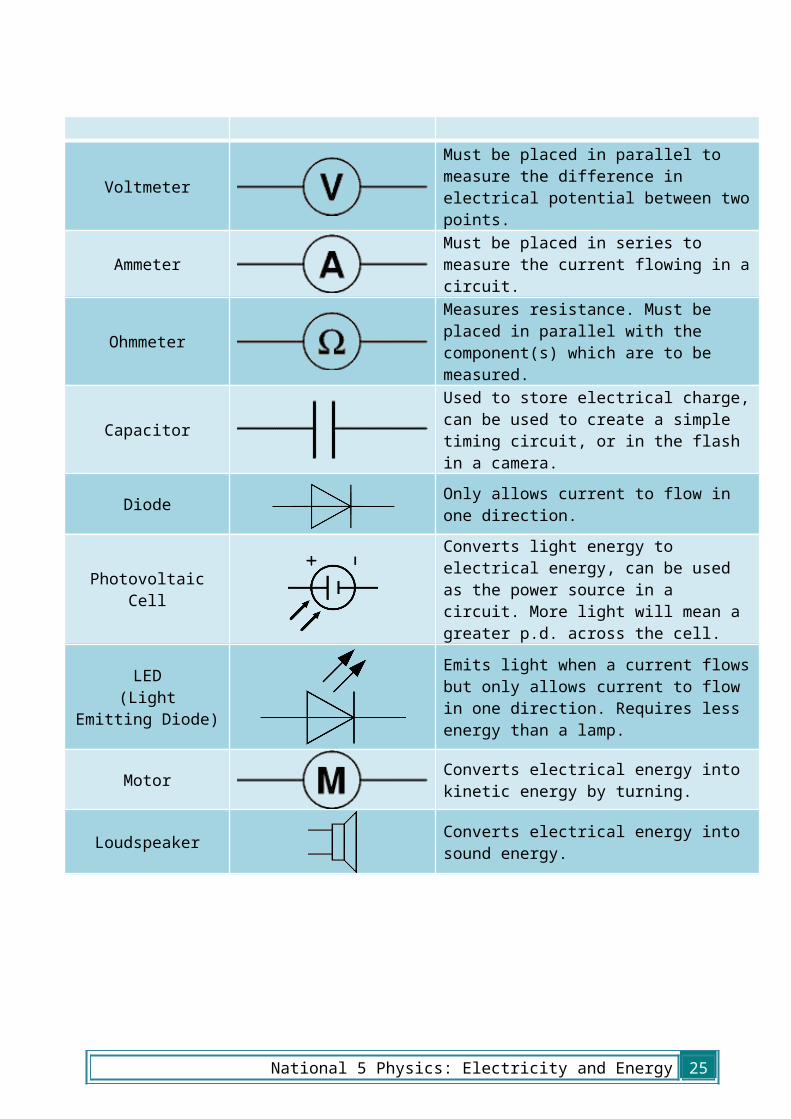
VoltmeterMust be placed in parallel to measure the difference in electrical potential between two points.
Ammeter Must be placed in series to measure the current flowing in a circuit.
OhmmeterMeasures resistance. Must be placed in parallel with the component(s) which are to be measured.
CapacitorUsed to store electrical charge, can be used to create a simple timing circuit, or in the flash in a camera.
Diode Only allows current to flow in one direction.
Photovoltaic CellConverts light energy to electrical energy, can be used as the power source in a circuit. More light will mean a greater p.d. across the cell.
LED(Light
Emitting Diode)
Emits light when a current flows but only allows current to flow in one direction. Requires less energy than a lamp.
Motor Converts electrical energy into kinetic energy by turning.
Loudspeaker Converts electrical energy into sound energy.
National 5 Physics: Electricity and Energy 19
Series Circuits
A circuit is described as a series circuit if the components appear one after the other in the circuit. An example is shown below.
To investigate the current in the circuit, we must place multiple ammeters in the circuit.
If we place an ammeter at each of these positions, we discover that the readings will be identical. In equation form, we can write this as
I 1=I2=I3=I 4…
The current in a series circuit is the same at all points.
We can also investigate potential difference in a series circuit.
20 National 5 Physics: Electricity and Energy
A potential difference is the difference in electrical potential between two points, so in a series circuit, the potential difference across each of the components must add up to the total potential difference across the supply.
If we call the supply p.d. Vs we write this as
V S=V 1+V 2+V 3…
The p.d. across each of the components in a series circuit adds up to the supply p.d.
Parallel Circuits
A circuit is described as a parallel circuit if the components are laid out next to each other, with common connections. An example is shown below.
To investigate the current in the circuit, we must place multiple ammeters in the circuit.
If we place an ammeter at each of these positions, we discover that the current splits between the branches, and the currents in the branches add up to the current at the supply.
In equation form, we can write this as
I S=I 1+ I 2+ I 3…
The total current in a parallel circuit is equal to the sum of the currents in the branches.
National 5 Physics: Electricity and Energy 21

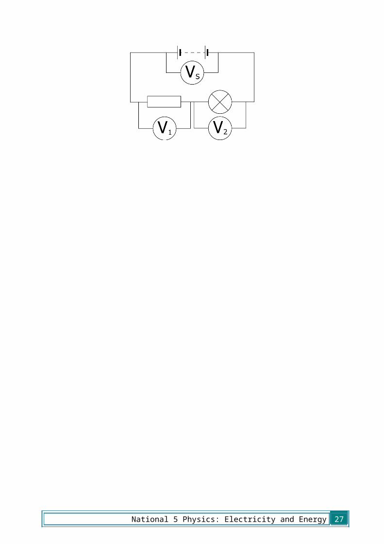
We can also investigate potential difference in the parallel circuit.
In a parallel circuit, the branches split off from the same point, so the potential at that point will be exactly the same. As a result, the potential difference across each component is the same as the supply.
We write this as
V S=V 1=V 2=V 3…
The p.d. across each of the components in a parallel circuit is equal to the supply p.d.
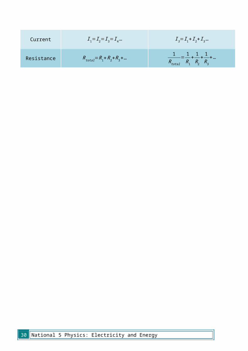
Circuit Rules
Measurement Series Circuits Parallel Circuits
Potential Difference V S=V 1+V 2+V 3… V S=V 1=V 2=V 3…
Current I 1=I2=I3=I 4… I S=I 1+ I 2+ I 3…
Resistance Rtotal=R1+R2+R3+…1R total
= 1R1
+ 1R2
+ 1R3
+…
22 National 5 Physics: Electricity and Energy
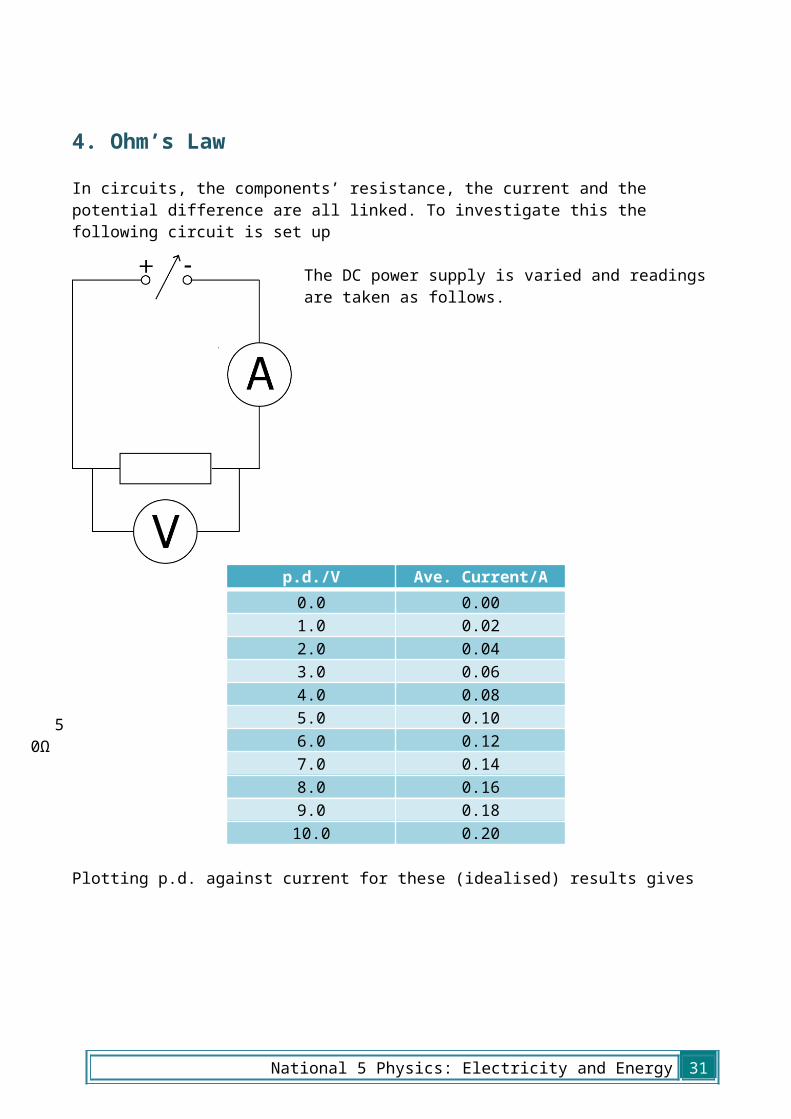
4. Ohm’s LawIn circuits, the components’ resistance, the current and the potential difference are all linked. To investigate this the following circuit is set up
The DC power supply is varied and readings are taken as follows.
p.d./V Ave. Current/A0.0 0.001.0 0.022.0 0.043.0 0.064.0 0.085.0 0.106.0 0.127.0 0.148.0 0.169.0 0.1810.0 0.20
Plotting p.d. against current for these (idealised) results gives
50Ω
National 5 Physics: Electricity and Energy 23
00.0
20.0
40.0
60.0
8 0.1 0.12
0.14
0.16
0.18 0.2
0123456789
10
Current / A
Pote
ntia
l Diff
eren
ce /
V
24 National 5 Physics: Electricity and Energy
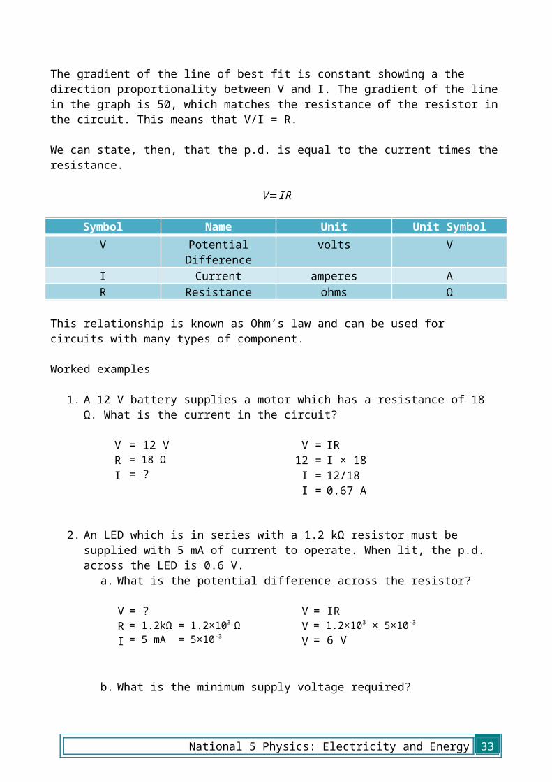
The gradient of the line of best fit is constant showing a the direction proportionality between V and I. The gradient of the line in the graph is 50, which matches the resistance of the resistor in the circuit. This means that V/I = R.
We can state, then, that the p.d. is equal to the current times the resistance.
V=IR
Symbol Name Unit Unit SymbolV Potential
Differencevolts V
I Current amperes AR Resistance ohms Ω
This relationship is known as Ohm’s law and can be used for circuits with many types of component.
Worked examples
1. A 12 V battery supplies a motor which has a resistance of 18 Ω. What is the current in the circuit?
VRI
= 12 V= 18 Ω= ?
V =12 =
I =I =
IRI × 1812/180.67 A
2. An LED which is in series with a 1.2 kΩ resistor must be supplied with 5 mA of current to operate. When lit, the p.d. across the LED is 0.6 V.
a. What is the potential difference across the resistor?
VRI
= ?= 1.2kΩ = 1.2×10³ Ω= 5 mA = 5×10⁻³
VVV
= IR= 1.2×103 × 5×10-3
= 6 V
b. What is the minimum supply voltage required?
VsupplyVLEDVresistor
= ?= 0.6 V= 6 V
Vsupply = VLED + VresistorVsupply = 0.6 + 6Vsupply = 6.6 V
National 5 Physics: Electricity and Energy 25

Resistance and Temperature
When current flows through components they often become warmer – this means that some energy is being changed from electrical energy into heat energy. While this is wanted in a toaster, it is not useful in most circuits.
In general, the resistance of a conductor will increase when it gets warmer. Resistors are considered to be ‘ohmic’ components and it is assumed that in normal conditions their resistance is constant. Lamps do not behave in this way though, as can be seen if the experiment to prove the relationship between current and voltage is repeated with a lamp instead of a resistor. As the lamp gets warmer, the resistance will increase.
LEDs and Diodes
The diode and the LED in the above list are very special. They only allow current to flow in one direction, but require a resistor in series to ensure correct operation. The resistor protects the diode ensuring that the p.d. across it, and the current through it are limited. If an LED requires 50 mA of current and 0.7 V across it we can use some of the rules from earlier in this section to calculate the size of resistor required.
The supply. p.d. is 5 V, we know that the LED should have 0.7 V across it, so the resistor must have
5 – 0.7 V = 4.3 V
across it as it is in series. We also know that, in series circuits, the current remains the same throughout. If the LED is operating correctly, the current must be 50 mA. We can now use Ohm’s law to calculate the correct value of resistor for the circuit.
V = 4.3 V V = IRI = 50 mA = 0.05 A
4.3 = 0.05 × R
R = ? R = 4.3/0.05R = 86 Ω
An 86 Ω resistor ensures that the current through and the p.d. across the LED are correct in this circuit.
5 V
26 National 5 Physics: Electricity and Energy
Potential Dividers
When a circuit is made in the configuration shown below, it is often called a potential divider, or a voltage divider. This is because each resistor takes a proportion of the total potential difference. How big a share of the potential difference each resistor takes depends on the size of the resistor, and the total resistance in the circuit.
We already know that in a series circuit, like this one, the current at each point in the circuit is the same. We also know that the potential difference across each resistor depends on the resistance and the current according to ohm’s law, V = IR. Therefore, as the current through each resistor is the same;
the higher the resistance, the higher the potential difference across the resistor.
This type of circuit can be used as a controller for other devices, and as a result it can be very useful to calculate the p.d. across an individual component.
In this circuit, for example, the total resistance is 10 Ω, as there is a 6 Ω and a 4 Ω resistor in series. We can say that the 6 Ω resistor should have 6/10 of the supply p.d. In this case then, V2 would be 12V. We can check this result using ohm’s law.
Vs = IRT V2 = IR210 = I ×(6+4) V2 = 2 × 6
I = 20/10 V2 = 12 VI = 2 A
It is possible to make a relationship which can be used for any potential divider. To calculate the p.d. across a component in a potential divider we multiply the supply p.d. by the fraction of the total resistance.
V 1=R1
(R1+R2)V s
Symbol Name Unit Unit SymbolV1 Potential Difference across
component 1volts V
R1 Resistance of component 1 ohms ΩR2 Resistance of component 2 ohms ΩVs Supply Potential Difference volts V
4 Ω
6 Ω
National 5 Physics: Electricity and Energy 27

This relationship can be used for any resistive components – not just resistors.
Worked Examples
1. What is the p.d. across the 20 Ω resistor?
VsR1R2V1
= 12 V= 20 Ω= 30 Ω= ?
V1V1V1V1V1
= R1/(R1 + R2) × Vs= 20/(20 + 30) × 12= 20/50 × 12= 0.4 × 12= 4.8 V
2. The potential difference across the variable resistor should be 6 V. The variable resistor can be any value between 1 kΩ and 10 kΩ. What should it be set to?
VsR1R2V1
= 15 V= 4.5 kΩ = 4500 Ω= ?= 6 V
V16
6(R1 + 4500)6 R1 + 27000
9 R1R1R1R1
= R1/(R1 + R2) × Vs= R1/(R1 + 4500) × 15= 15 × R1= 15 R1= 27000= 27000/9= 3000= 3.0 k Ω
12 V
30 Ω
20 Ω
15 V4.5 kΩ
28 National 5 Physics: Electricity and Energy

5. Electrical Power
When we are using electrical appliances, it is useful to have an idea of how much energy they will require. This leads to the definition of electrical power.
Power is defined as the amount of energy transformed per second, as shown in the equation below
P= Et
Symbol Name Unit Unit SymbolP Power watts WE Energy joules Jt time seconds s
Different appliances will transform more or less electricity. Often the highest powered ones will be those which transform electrical energy into heat energy, for example a hair dryer. We often describe this as the power consumption.
AppliancePower
transformation/W
Oven 3000Dishwasher 1400
Iron 1100Hair Dyer 1500Microwave 1000
TV 250Stereo 60
Filament Lamp 100Energy Saving
Lamp 11Drill 750
Fridge 1400
National 5 Physics: Electricity and Energy 29
Worked examples
1. What is the power of a television which transforms 0.5 MJ of energy in 1 hour?
PEt
= ?= 0.5 MJ= 1 × 60 × 60 = 3600 s
P =P =P =
E/t0.5×106 /3600139 W
2. A 1500 W hairdryer is used for 5 minutes, how much energy is transformed?
PtE
= 1500W= 5 x 60 = 300 s= ?
P =1500
=E =E =E =
E/tE/3001500 × 300450000450 kJ
Power, Current and Potential Difference
We can also relate power to current and potential difference. Potential difference is the amount of energy supplied per coulomb of charge supplied as the charge passes the power source (remember, 1 V = 1 J/C). Current is the amount of charge per second.
If we multiply the potential difference across a circuit by the current through it we have:
volts × amperes= joules/coulomb × coulomb/second
= joules/second
Earlier it was shown that power can be defined as the energy per unit time, so that is joules per second which means that power must also equal current multiplied by voltage.
This is written as followsP=IV
Symbol Name Unit Unit SymbolP Power watts WI Current amperes AV Potential
differenceVolts V
30 National 5 Physics: Electricity and Energy
National 5 Physics: Electricity and Energy 31

It is possible to get two further useful relationships if we combine this equation with Ohm’s law.
The first uses current and resistance:
V=IR
and
P=IV
substituting for V
P=I × IR
simplifying this leaves
P=I 2R
The second new equation we can make uses potential difference and
resistance.V=IR
which can be rearranged as
I=VR
substituting this equation into
P=IV
to give
P=VR×V
simplifying this leaves
P=V2
R
P=I 2RP=V
2
R
Symbol Name Unit Unit SymbolP Power watts WI Current amperes AR Resistance ohms ΩV Potential
Differencevolts V
32 National 5 Physics: Electricity and Energy
Worked examples
1. A vacuum cleaner is connected to the UK mains (rated at 230 V) and 8.9 A of current flows through the circuit. What power is being transformed?
PVI
= ?= 230 V= 8.9 A
PVV
= IV= 230 × 8.9= 2047 W
2. The elements of a toaster have a total resistance of 15 Ω, the toaster is rated at 1650 W. What current does it draw?
PI
R
= 1650 W= ?= 15 Ω
P1650
I2II
= I2R= I2 × 15= 1650/15= √110= 10.5 A
3. A label on a 60 W lamp states that it requires a 12 V supply to operate at full power. What is the lamp’s resistance?
PVR
= 60 W= 12 V= ?
P60RR
= V2/R= (12 × 12)/R= 144/60= 2.4 Ω
National 5 Physics: Electricity and Energy 33